


Languages
Pages
Legal


Analysis Between a Beam Supported Structure and a Flat Plate Structure
INTRODUCTION
General:
When a slab is supported directly on columns, without beams and girders, it is called a flat plate
slab. Although thicker and more heavily reinforced than slabs in beam and girder construction,
flat plate slabs are advantageous because they offer no obstruction to passage of light (as beam
construction does); savings in story height and in the simpler form work involved; less danger of
collapse due to overload; and better fire protection with a sprinkler system because the spray is
not obstructed by beams.
Objective of the Study:
The objectives of the study were:
To analyze and design a six-storied beam supported building system.
To analyze and design the same building for flat plate slab system.
To compare the concrete and steel requirement of the two types of building.
Methodology
i. Analysis Phase
Requires extensive FEM analysis
Correction of analysis results for BNBC since in the software we used UBC* 94 code
Development of shear force & moment envelope to determining the critical sections & values of
critical shear and moment for design
ii. Design & Estimation Phase
Slab, Beam & Column Design & Estimation through manual calculation
ORGANIZATION of the Thesis Works:
The thesis comprises of the following five chapters:
Chapter- 1: Includes a brief introduction, objectives of the study andORGANIZATIONS of the
thesis paper.
Chapter- 2: Includes compilation of the relevant literature that has been reviewed for the
study.
Chapter- 3: Includes a detailed description of the analysis.
Chapter- 4: Includes the comparison of the results of analysis.
Chapter- 5: Includes conclusions and recommendations for further study.
CHAPTER II LITERATURE REVIEW
Introduction
This chapter elaborated a detailed literature review that was required for the through
understanding and proper conducting of this work.
Wind Load
The minimum deign wind load on buildings and components shall be determined based on the
velocity of the wind, the shape and size of the building and the terrain exposure condition of the
site. The design wind load shall include the effects of the sustained wind velocity component and
the fluctuating component due to gusts. For slender buildings, the design wind load shall also
include additional loadings effects due to wind induced vibrations of the building.
Terrain exposure
A terrain exposure category that adequately reflects the surface roughness characteristics of the
ground shall be determined for the building site, taking intoACCOUNT the variations in ground
roughness arising from existing natural topography, vegetation and man made constructions. The
exposure category is divided into three types-
1. Exposure A: Urban and sub-urban areas, industrial areas, wooded areas, hilly or other terrain
covering at least 20 percent of the area with obstructions of 6 m or more in height and extending
from the site at least 500 m or10 times the height of the structure whichever is greater.
2. Exposure B: Open terrain with scattered obstructions having heights generally less Than 10 m
extending 800 m or more from the site in any full quadrant. This category includes air fields, open
park lands, sparsely built-up outskirts of towns, flat open country and grasslands.
3. 3. Exposure C: Flat and unobstructed open terrain, coastal areas and riversides facing Large
bodies of water, over 1.5 km or more in width, it extends inland from the
shoreline 400m or 10times the height of structure, whichever is greater.
Wind pressure on building:
Wind is one of the significant forces of nature that must be considered in the design of buildings.
Structural load applied by high winds is readily appreciated, even if the method of determining
them is not so easily understood. Other effects that can be caused even by moderate breezes
are commonly overlooked, however, because very often there is no obvious link between wind
and the behavior of a building.
Rain leakage around flashings and through joints in curtain walls may be due to a pressure
gradient across the wall and the functioning of ventilating and heating systems may be affected
by pressure distributions where ducts and openings are located.
Thus it is only the structural engineer who must consider wind action but the architect and
mechanical engineer as well. The latter are often concerned with the maximum pressures that
can reasonably by expected to occur during the useful life of the structure.

Conversion from wind speed to wind pressure:
Wind pressures exerted on a structure depend on the speed of the wind as well as the interaction
between the airflow and the structure. The wind speed to be used in computing the design
pressure depends on the particular component of the building being designed. For structural
purposes the maximum value is required and will vary with the geographical location.
Meteorological records of wind speed are analyzed to yield the most probable maximum that will
be equaled or exceeded, on the average, once during a given period of a time comparable to the
life of a structure.
Sustained Wind pressure
Qz = Cc * Ci* C z* Vb2
Where, Qz = Sustained wind pressure at height z, KN / m2
Ci = Structural importance coefficient
Cc = Velocity – to – pressure conversion
Cz = Combined height & exposure coefficient
Vb = basic wind speed in Km / hr
Design wind pressure:
Pz = Cg * Cp* Qz
Where,
Pz = design wind pressure at height z, KN / M2
Cg = gust coefficient
Cp = pressure coefficient for structures or components
Qz = sustained wind pressure
Pressure coefficients
Pressure coefficients used in practice have usually been obtained experimentally by testing
models of different types of structures in wind tunnels. Commonly used coefficients refer to the
average pressure or suction over a surface. Tangential forces are considered insignificant, so
that the forces referred to act at right angles to the surfaces in question.
Variables affecting pressure distributions
Building shape:
Pressure on certain parts of a structure is rather sensitive to changes in the shape of the building.
The suctions on the windward roof slope, for instance, very considerably with the slope of the
roof, the ratio of height to width, and the ratio of width to length of the building. Suctions on the
leeward wall, on the other hand, are not greatly affected by such variables.

Sometimes shape details have an unexpectedly large effect on the wind pressure distribution.
Parapet walls, large chimneys, silos and spires may have considerable influence and often the
only way to assess such effects is to test a scale model in a wind tunnel.
Openings:
The size and location of opening such as windows and doors determine the internal pressure that
must be considered in the calculation of net forces of walls and roofs. Internal pressure tend to
take on the values appropriate to the exterior of the wall in which in which the opening
predominate. If they are small and uniformly distributed, values of ± 2 are recommended, the
more unfavorable of the two to be considered in each case.
Wind direction:
The orientation of a building to the wind has a market effect on pressure distribution, particularly
on suction maxima, which occur over a small area near the leading edges of roofs.
Increase of wind speed with height:
Since the wind speed and consequently the velocity pressure increase with height above the
ground, a height factor is applied to the basic pressure in the design of building.
Shielding:
Other buildings, trees and similar large objects in the immediate vicinity have a bearing on
pressure distribution. The shielding provided is usually difficult to estimate and model tests
provide the most convenient means of determining design values. The assignment of reduction
for shielding is completed by the fact that conditions could change during the life of the structure.
Shielding does not always has a beneficial effect, and in some cases suction coefficients should
be increased because of the proximity of a neighboring building.
Wind pressures on various part of building
Roofs:
The roof is usually the critical area in the wind design of low building, particularly residential
structures. Where it is made up of light- weight components particular attention must be paid to
anchorage details because of the suction condition prevailing over most, if not all, of it. A good
example of such precautions is the time –honored custom of weighting roofs in alpine areas with
large stones.
Critical angle, windward slope:
For every sloped roof there is a certain slope angle at which the suction coefficients over the
windward slope reaches a numerical maximum.

Steep roofs:
As the roof slope increases beyond the critical angle the average pressure coefficient decreases
numerically to zero; it the increases in a positive direction, indicating pressure, to maximum of +
0.8 or so for a slope angle of 90 degrees.
Leeward slope:
The effect of slope and building dimension ratios are much less pronounced of suctions on the
leeward slope and for general purposes could probably be disregarded.
Local suctions:
Local suctions are more serious for wind at an angle (usually about 45 degree) to the side of the
building.
Walls:
For tall, slender structures the design of the walls and the frame, with regard to overturning
moment, are likely to be critical. The trend toward high-rise buildings and
curtain wall construction may lead to greater problems in limiting sway and specifying the
strength of fastenings for the wall panels.
Earthquake Load
Minimum design earthquake forces for buildings, structures or components of buildings or
structures, can be calculated either by the Equivalent static force method of by the Dynamic
response method. We will calculate earthquake load by equivalent static force method.
Seismic zoning map
The seismic zoning map of Bangladesh is provided by BNBC. Based on the severity of the
probable intensity of seismic ground motion and damages, Bangladesh has been divided into
three seismic zones.
These are –
1. Zone-1
2. Zone-2
3. Zone-3
Selection of lateral force method
Seismic lateral forces on primary framing systems shall be determined by using either the
equivalent static force method of the dynamic response method with the restriction given bellow-
a) The equivalent static force method
1. All structures, regular or irregular, in seismic zone 1 and in structure importance
2. Regular structures less than 75 m in height with lateral force resistance provided by structural
systems listed in BNBC except case 4 below.
3. Irregular structures not mire than 20 m in height.

4. A tower like building or structure having a flexible upper portion supported on a rigid lower portion
where:
Both portion of the structure considered separately can be classified as regular structures,
The average story stiffness of the lower portion is at least tin times the average storey stiffness of
the upper portion.
The period of the entire structure is not greater than 1.1 times the period of the upper portion
considered as a separate structure fixed at he base.
b) The Dynamic response method shall be used for structures of the following types-
1. Structures 75 m or more in height except as permitted by case a (1).
1. Structures having stiffness, weight or geometric vertical irregularity of type 1, 2& 3 is defined
in the BNBC table or structures not described.
2. Structure over 20 m in height in seismic zone 3 not having the same structural
system throughout their height except as permitted by BNBC.
1. Structures, regular or irregular, located on soil profile type S4 as described, which have a period
greater than .1 second. The analysis shall include the effect of the soil at the site.
Seismic dead load
Seismic dead load, W, is the total dead load of a building or a structure, including permanent
partitions and applicable portions of other loads listed below:
1) In storage and warehouse occupancies, a minimum of 25 percent of the floor live
load shall be applicable.
2) Where an allowance for partition load is include in the floor design in accordance
with BNBC all such loads but not less than .6 KN / m2 shall be applicable.
3) Total weight of permanent equipment shall be included
Equivalent static force method
Design base shear:
V = (ZIC / R) * W
Where,
Z = Seismic zone coefficient
I = Structure importance coefficient
R = Response modification coefficient for structural systems
W = Total seismic dead load
C = Numeric coefficient given by the relation-
C = (1.25 S) / T2/3
Where,
S = Site coefficient for soil characteristics
T = Fundamental period of vibration in seconds
Where, T = Ct (hn) 3/4

Ct = 0.083 for steel moment resisting frames
= 0.073 for reinforced concrete moment resisting frames and
Eccentric braced steel frames.
= 0.049 for all other structural systems.
hn = Height in meters above the base to level n
Vertical distribution of lateral force
In the absence of a more rigorous procedure, the total lateral force, which is the base shear V,
shall be distributed along the height of the structure in accordance with the following equation:
V = Ft + ∑ Fi
Where,
Fi = Lateral force applied at storey level I
Ft = Concentrated lateral force considered at the top of the building in
Addition to the force Fn
Where,
Ft = 0.070 TV ≤ 0.25V When T > 0.70 second
Ft = 0.0 When T ≤ 0.70 second
The remaining portion of the base shear (V-Ft) shall be distributed over the height of the building,
including level – n, according to the relation:
Fi = (V- Ft) * W l * hi) / ∑Wi * hi
Direct Design Method
Assumption
Moments in two way slabs can be found using the semi empirical direct design method, subjected
to the following restrictions:
1. There must be a minimum of three continuous spans in etch direction.
2. The panels must be rectangular, with the ratio of the longer to the shorter spans
within a panel not greater than 2.
1. The successive span lengths in each direction must not differ by more than one-third
of the longer span.
1. Columns may be offset a maximum of 10 percent of the span in the direction of the
offset from either axis between center lines of successive columns.
5. Loads must be due to gravity only and the live load must not exceed two times the
dead load.
6. If beams are used on the column lines, the relative stiffness of the beams in the two
perpendicular directions, given by the ratio: α1l2² / α2l12, must be between 0.2 and 5.0

Static moment
For purpose of calculating the total static moment Mo in a panel, the clear span ln in the direction
of moments is used. The clear span is defined to extend from face to face of the columns,
capitals, brackets, or walls but is not to be less than 0.65 l1. The total factored moment in a
span, for a strip bounded laterally by the centerline of the panel on each side of the centerline of
supports is-
Mo = wu l2 ln² / 8
Reciprocal Method
A simple, approximate design method developed by Bresler has been satisfactorily verified by
comparison with results of extensive tests and accurate calculation. The column interaction
surface can alternatively be plotted as a function of the axial load Pn and eccentricities ex = Mny /
Pn and ey = Mnx / Pn, The surface S1 of fig-a can be transformed into an equivalent failure surface
S2, as shown in fig – b, where ex and ey are plotted against 1 / Pn rather than Pn. Thus, ex = ey = 0
corresponds to the inverse of the capacity of the column if it were concentrically loaded, Po and
this is plotted as point C. For ey = 0 and any given value of ex, there is a load Pnyo that would
result in failure. The reciprocal of this load is plotted as point A. Similarly , for ex = 0 and any
given value of ey, there is a certain load Pnxo that would cause failure, the reciprocal of which is
point B. The values of Pnxo and Pnyo are easily established, for known eccentricities of loading
applied to a given column, using the methods already established for uniaxial bending or using
design charts for uniaxial bending. An oblique plane S2 is defined by the three points A, B, C. This
plane is used as an approximation of the actual failure surface.
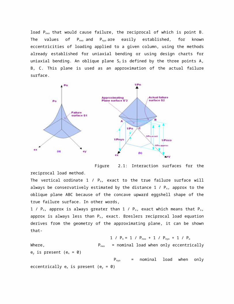
Figure 2.1: Interaction surfaces for the reciprocal load method.

The vertical ordinate 1 / Pn, exact to the true failure surface will always be conservatively
estimated by the distance 1 / Pn, approx to the oblique plane ABC because of the concave
upward eggshell shape of the true failure surface. In other words,
1 / Pn, approx is always greater than 1 / Pn, exact which means that Pn, approx is always less
than Pn, exact. Breslers reciprocal load equation derives from the geometry of the approximating
plane, it can be shown that-
1 / Pn = 1 / Pnxo + 1 / Pnyo + 1 / Po
Where, Pnxo = nominal load when only eccentrically ey is present (ex = 0)
Pnyo = nominal load when only eccentrically ex is present (ey = 0)
Po = nominal load for concentrically loaded column.
The above equation has been found to be acceptably accurate for design purposes provided ρn ≥
0.10ρo. It is not reliable where biaxial bending is prevalent and accompanied by an axial force
smaller than ρo / 10.
Analysis and Design Basis:
This thesis is prepared properly based on Bangladesh National Building Code. Every part of this
thesis is properly maintained the recommendation of this code. Here some features are
described below-
Bangladesh country paper for WCDR 7
Does your country have building codes of practice and standards in place?
Which takes into account seismic risk?
The National Building Code was formulated and published in 1993. Bangladesh does not have
any separate code for the design or construction of earthquake resistant structure. However, a
new seismic zoning map and detailed seismic design provisions were incorporated into the
National Building Code in 1993 that replaces the code prepared in 1979. The Bangladesh
Earthquake Society has recently published a Bengali translation of the Guidelines for Earthquake
Resistant Non-Engineered Construction, written by the International Association of Earthquake
Engineering 3. The enforcement of the standards presented in the National Building Code
requires close monitoring by concerned agencies. The shortage of trained staff to monitor new
construction impedes the effectiveness of the building standards.
Analysis Software:
There is much finite element software for analyzing structure. ETABS is one of them. Every
analysis is this thesis is done by using ETABS 8 package. In the following paragraph we will
discuss some of its features-
Introduction
ETABS is a sophisticated, yet easy to use, special purpose analysis and design program
developed specifically for building systems. ETABS version 8 features an intuitive and powerful
graphical interface coupled with unmatched modeling, analytical and design procedures, all
integrated using a common database. Although quick and easy for simple structures, ETABS can
also handle the largest and most complex building models, including a wide range of nonlinear
behaviors, making it the tool of choice for structural engineers in the building industry.
History and advantages of ETABS
Dating back more than 30 years to the original development of TABS, the predecessor of ETABS,
it was clearly recognized that buildings constituted a very special class of structures. Early
releases of ETABS pro-vided input, output and numerical solution techniques that took into
consideration the characteristics unique to building type structures, providing a tool that offered
significant savings in time and increased accuracy over general purpose programs. As computers
and computer interfaces evolved, ETABS added computationally complex analytical options such
as dynamic nonlinear behavior, and powerful CAD-like drawing tools in a graphical and object-
based interface. Although ETABS Version 8 looks radically different from its predecessors of 30
years ago, its mission remains the same: to provide the profession with the most efficient and
comprehensive software for the analysis and design of buildings. To that end, the current release
follows the same philosophical approach put forward by the original programs, namely: Most
buildings are of straightforward geometry with horizontal beams and vertical columns. Although
any building configuration is possible with ETABS, in most cases, a simple grid system defined by
horizontal floors and vertical column lines can establish building geometry with minimal effort.
Many of the floor levels in buildings are similar. This commonality can be used numerically to
reduce computational effort. The input and output conventions used correspond to common
building technology. With ETABS, the models are defined logically floor-by-floor, column, bay-by-
bay and wall-by-wall and not as a stream of non-descript nodes and elements as in general
purpose programs. Thus the structural definition is simple, concise and meaningful. In most
buildings, the dimensions of the members are large in relation to the bay widths and story height.
Those dimensions have a significant effect on the stiffness of the frame ETABS corrects for such
effects in the formulation of the member stiff-ness, unlike most general-purpose programs that
work on center-line-to-center-line dimensions. The results produced by the programs should be in
a form directly usable by the engineer. General purpose computer programs produce result in a
general form that may need additional processing before they are useable in structural design.
An integrated approach
ETABS is a completely integrated system. Embedded beneath the simple, intuitive user interface
are very powerful numerical methods, design procedures and international design codes, all
working from a single comprehensive database. This integration means that you create only one
model of the floor systems and the vertical and lateral framing system to analyze and design the
entire building. Everything you need is integrated into one versatile analysis and design package
with one Windows-based graphical user interface. No external modules are maintained, and no
data is transferred between programs or modules. The effects on one part of the structure from
changes in another part are instantaneous and automatic. The integrated modules include:
Drafting module for model generation.
Seismic and wind load generation module.
Gravity load distribution module for the distribution of vertical loads to columns and beams when
plate bending floor elements are not provided as a part of the floor system.
Finite element-based linear static and dynamic analysis module.
Finite element-based nonlinear static and dynamic analysis module.
Output display and report generation module.
Steel frame design module (column, beam and brace).
Concrete frame design module (column and beam).
Composite beam design module
Steel joist design module
Shear wall design module.
Modeling features
The ETABS building is idealized as an assemblage of area, line and point object. Those objects
are used to represent wall, floor, column, beam, brace and link/spring physical members. The
basic frame geometry is defined with reference to a simple three dimensional grid system. With
relatively simple modeling techniques, very complex farming situations may be considered. The
buildings may be unsymmetrical and non-rectangular in plan. Torsional behavior of the floors and
inter story compatibility of the floors are accurately reflected in the result. The solution enforces
complete three dimensional displacement compatibility, making it possible to capture tubular
effects associated with the behavior of tall structures having relatively closely spaced columns.
Semi-rigid floor diaphragms may be modeled to capture the effects of in plane floor deformations.
Floor objects may span between adjacent levels to create sloped floors (ramps), which can be
useful for modeling parking garage structures. Modeling of partial diaphragms, such as in
mezzanines, setbacks, atriums and floor openings, is possible without the use of artificial
(“dummy”) floors and column lines. It is also possible to model situations with multiple
independent diaphragms at each level, allowing the modeling of buildings consisting of several

towers rising from a common base. The column, beam and brace elements may be non-
prismatic, and they may have partial fixity at their end connections. They also may have uniform,
partial uniform and trapezoidal load patterns, and they may have temperature loads. The effects
of the finite dimensions of the beams and columns on the stiffness of a frame system are
included using end offsets that can be automatically calculated. The floors and walls can be
modeled as membrane elements with in-plane stiffness only, plate bending elements with out-of-
plane stiffness only or full shell-type elements, which combine both in-plane and out-of-plane
stiffness. Floor and wall objects may have uniform load patterns in-plane or out-of-plane, and
they may have temperature loads. The column, beam, brace, floor and wall objects are all
compatible with one another.
Analysis features
Static analysis for user specified vertical and lateral floor or story loads are possible. If floor
elements with plate bending capability are modeled, vertical uniform loads on the floor are
transferred to the beams and columns through bending of the floor elements. Otherwise, vertical
uniform loads on the floor are automatically converted to span loads on adjoining beams, or point
loads on adjacent columns, thereby automating the tedious task of transferring floor tributary
loads to the floor beams without explicit modeling of the secondary framing. The program can
automatically generate lateral wind and seismic load patterns to meet the requirements of various
building codes. Three-dimensional mode shapes and frequencies, modal participation factors,
direction factors and participating mass percentage are evaluated using eigenvector. P-Delta
effects may be included with static or dynamic analysis. Response spectrum analysis, linear time
history analysis, nonlinear time history analysis, and static nonlinear (pushover) analysis are all
possible. The static nonlinear capabilities also allow you to perform incremental construction
analysis so that forces that arise as a result of the construction sequence are included. Result
from the various static load conditions may be combined with each other or with the result from
the dynamic response spectrum or time history analysis. Output may be viewed graphically,
displayed in tabular output, sent to a printer, exported to a database file, or saved in an ASCII file.
Types of output include reactions and member forces, mode shapes and participation factors,
static and dynamic story displacements and story shears, inter story drifts and joint
displacements, time history traces, and more.
Shell element internal forces
The shell element internal forces, like stresses, act throughout the element. They are present at
every point on the mid surface of the shell element. ETABS reports values for the shell internal
forces at the element nodes. It is important to note that the internal forces are reported as forces

and moments per unit of in-plane length. The basic shell element forces and moments are
identified as F11, F22, F12, M11, M22, M12, V13 and V23. You might expect that there would also be an
F21 and M21, but F21 is always equal to F12 and M21 is always equal to M12, so it is not actually
necessary to report F21and M21.
Conclusion
Materials problem is a great problem in our country especially the shortage of constriction raw
materials in our country. This thesis is based on the previously discussed topics.
This thesis may result an effective solution of this problem.
ANALYTICAL STUDY
General:
The analysis is made by using ETABS finite element package. Analysis was made for two
different types of building systems. One is beam column slab system and another is flat plate slab
system. Total ten loads combination was considered for design of different elements of the
building. The whole analysis and design was performed based on ACI and BNBC code.
The Building Geometry
The building geometries are as follows:
Option I:
All the floors have 16 columns. All the slabs of the structure are beam supported. Story height is
10 ft. column and beam size is different. The layout is shown in figure 3.2
Option II:
All the floors have 16 columns. All the slabs are directly supported on column (Flat Plate
structure). Column size is different. The layout is shown in figure 3.1
The Loads Considered
Dead Load, D. L = 50 psf (for wall)
Floor Finish, F. F = 30 psf
Live Load, L. L = 40 psf
Load Combination
COMB 1 = 1.4 D.L
COMB 2 = 1.4 D.L + 1.7 L.L
COMB 3 = 0.75 (1.4 D.L + 1.7 L.L + 1.7 WLX)
COMB 4 = 0.75 (1.4 D.L + 1.7 L.L. – 1.7 WLX)
COMB 5 = 0.75 (1.4 D.L + 1.7 L.L + 1.7 WLY)
COMB 6 = 0.75 (1.4 D.L + 1.7 L.L – 1.7 WLY)
COMB 7 = 0.75 (1.4 D.L + 1.7 L.L + 1.87 ELX)

COMB 8 = 0.75 (1.4 D.L + 1.7 L.L – 1.87 ELX)
COMB 9 = 0.75 (1.4 D.L + 1.7 L.L + 1.87 ELY)
COMB 10 = 0.75 (1.4 D.L + 1.7 L.L – 1.87 ELY)
Legends:
D.L = Dead load
L.L = Live load
WLX = Wind load in X direction
WLY = Wind load in Y direction
EQX = Earthquake load in X direction
EQY = Earthquake load in Y direction
Figure 3.1: Option II (Typical floor plan of the flat plate structure).
Wind Load Calculation
This load is a function of the wind speed which in turn is depended on the location of the building,
the exposure of the location, gusting effect, importance of the building and the geometry of the
building. Wind load calculations were done by UBC – 94 codes by ETABS. The wind speed was
adjusted to convert it to BNBC code. In this study, wind load was calculated by the diaphragms
method.

Input data
Windward Coefficient, Cq = 1.4
Leeward Coefficient, Cq ≈ 0
Wind Speed, V = 210 km / hr (131.25 mph)
Exposure Type = B, Importance Factor = 1.0
Along X axis, Wind Direction Angle = 00
Along Y axis, Wind Direction Angle = 900
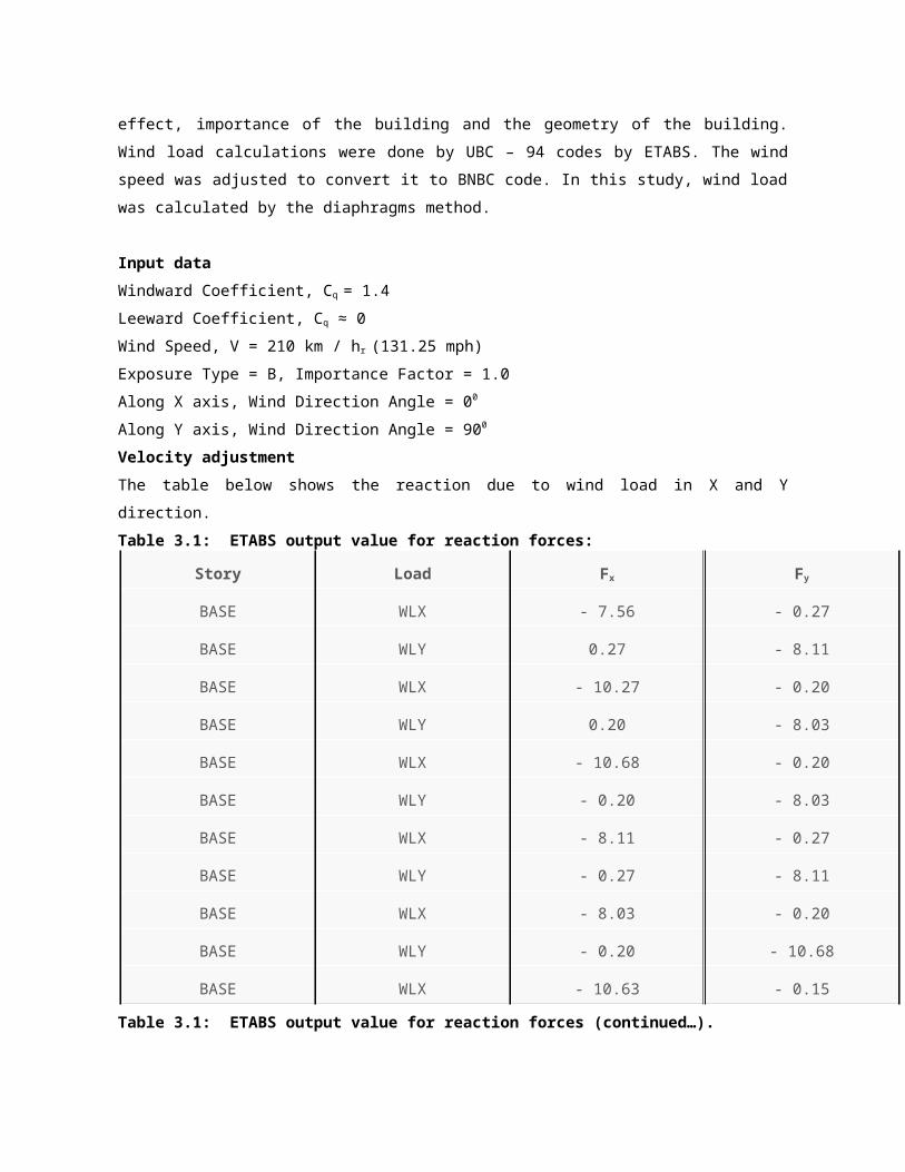
Velocity adjustment
The table below shows the reaction due to wind load in X and Y direction.
Table 3.1: ETABS output value for reaction forces:
Story Load Fx Fy
BASE WLX - 7.56 - 0.27
BASE WLY 0.27 - 8.11
BASE WLX - 10.27 - 0.20
BASE WLY 0.20 - 8.03
BASE WLX - 10.68 - 0.20
BASE WLY - 0.20 - 8.03
BASE WLX - 8.11 - 0.27
BASE WLY - 0.27 - 8.11
BASE WLX - 8.03 - 0.20
BASE WLY - 0.20 - 10.68
BASE WLX - 10.63 - 0.15
Table 3.1: ETABS output value for reaction forces (continued…).
Story Load Fx Fy
BASE WLY - 0.15 - 10.63
BASE WLX - 10.33 - 0.15
BASE WLY 0.15 - 10.63
BASE WLX -7.64 - 0.20

BASE WLY 0.20 - 10.68
BASE WLX - 7.64 0.20
BASE WLY 0.20 - 10.27
BASE WLX - 7.56 0.27
BASE WLY 0.27 - 7.56
BASE WLX - 10.33 0.15
BASE WLY 0.15 - 10.33
BASE WLX - 10.27 0.20
BASE WLY 0.20 -7.64
BASE WLX - 10.63 0.15
BASE WLY - 0.15 - 10.33
BASE WLX - 10.68 0.20
BASE WLY - 0.20 - 7.64
BASE WLX - 8.03 0.20
BASE WLY - 0.20 - 10.27
BASE WLX - 8.11 0.27
BASE WLY - 0.27 -7.56
Summation WLX - 146.48 0
Summation WLY 0 - 146.48
From Hand Calculation:
Table 3.2: Wind force X / Y direction.

height Vb2 qz Pz Pz A F
H(m) Cc Ci cz 210 (KN/m2) Cg Cp (KN/m2) (psf) (sft) (Kips)
F-1 3.05 4.7E-5 1 0.37 44100 0.76 1.38 1.4 1.48 30.92 250 7.73
F-2 6.1 4.7E-5 1 0.41 44100 0.86 1.38 1.4 1.68 35.08 500 17.54
F-3 9.15 4.7E-5 1 0.50 44100 1.03 1.38 1.4 2.01 41.97 500 20.99
F-4 12.2 4.7E-5 1 0.57 44100 1.17 1.38 1.4 2.28 47.77 500 23.89
F-5 15.24 4.7E-5 1 0.63 44100 1.30 1.38 1.4 2.52 52.74 500 26.37
F-6 18.3 4.7E-5 1 0.68 44100 1.41 1.38 1.4 2.74 57.29 500 28.65
Summation of F 125.16
So the adjusted wind speed in both direction,
V = 131.25 * √ (125.16 / 146.48) = 121.32 mph
Table 3.3: The table below shows the reaction due to wind load in X and Y direction after
correction of wind speed.
Story Load Fx Fy
BASE WLX - 6.44 - 0.25
BASE WLY 0.25 - 6.94
BASE WLX - 8.75 - 0.14
BASE WLY 0.2 - 6.83
BASE WLX - 9.15 - 0.14
Table 3.3: The table below shows the reaction due to wind load in X and Y direction after
correction of wind speed (continued…).
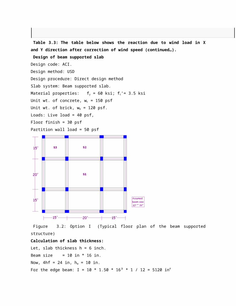
Design of beam supported slab
Design code: ACI.
Design method: USD
Design procedure: Direct design method
Slab system: Beam supported slab.
Material properties: fy = 60 ksi; fc’= 3.5 ksi

Unit wt. of concrete, wc = 150 psf
Unit wt. of brick, wb = 120 psf.
Loads: Live load = 40 psf,
Floor finish = 30 psf
Partition wall load = 50 psf
Figure 3.2: Option I (Typical floor plan of the beam supported structure)
Calculation of slab thickness:
Let, slab thickness h = 6 inch.
Beam size = 10 in * 16 in.
Now, 4hf = 24 in, hw = 10 in.
For the edge beam: I = 10 * 1.50 * 16³ * 1 / 12 = 5120 in4
For the interior beam: I = 10 * 2 * 16³ * 1 / 12 = 6827 in4
For the slab strips:
For the 7.92 ft edge width: I = 7.92 * 12 * 6³ * 1/12 = 1711 in4
For the 17.5 ft width: I = 17.50 * 12 * 6³ * 1 / 12 = 3780 in4
Thus for the edge beam α1 = 5120 / 1711 = 2.99
For the interior beam α2 = 6827 / 3780 = 1.81
Average value, αm = 2.40
For 15’*15’ slab panel: β = 1
For 15’*20’ slab panel: β = (20 – 10 / 12) / (15 – 10 / 12) = 19.17 / 14.17 = 1.35
For 20’*20’ slab panel: β = 1
Now, slab thickness h = [12 * 19.17{0.8+ (60000 / 200000)}] / [36 + 9 * 1] = 5.62 in.
The 3.50 in limitation clearly does not control in this case. 6 in. depth is ok.
Factored load, W = 285 psf.
For 15 ft * 15 ft panel:
Slab – beam strip centered on the Interior column line.
Mo = 0.285 * 17.50 *14.17² * 1 / 8 = 137 ft – kip.
Interior negative moment: 137 * 0.70 = 96 ft-kip
Positive moment: 137 * 0.57 = 78 ft – kip
Exterior negative moment: 137 * 0.16 = 22 ft – kip.
The torsional constant, C = {1 – (0.63 * 10 / 10)16 * 10³ / 3 + {1 – (0.63*6 / 10)10 * 6³ / 3
= 3681 in4
Now, l2 / l1 = 1; α1l2 / l1 = 1.81; βt = 3681 / (2*3780) = 0.50
Exterior negative moment 90%, positive moment 75%, Interior negative moment 75% is taken by
column strip.
The table below is showing slab strip moment at different locations for 15’*15’ panel.
Table 3.5: Slab-beam strip centered on the Interior column line.
Slab-beam strip Column strip slab moment ft-
kip
Middle strip slab moment ft-kip
Exterior negative moment 3 2.2
Positive moment 9 20
Interior negative moment 11 24
Slab-beam strip at the edge of the building:-
Mo = 0.285 * 7.92 * 14.17² * 1 / 8 = 62 ft-kips
Interior negative: 62 * 0.70 = 43 ft-kips
Positive: 62 * 0.57 = 35 ft-kips
Exterior negative: 62 * 0.16 = 10 ft-kips
Now, l2 / l1= 1; α112 / l1 = 2.99 * 1 = 2.99; βt = 3681 / (2 * 1711) = 1.10
Positive moment 75%, Exterior negative moment 90%, Interior negative moment 75% is taken by
column strip.
Table 3.6: Slab-beam strip at the edge of the building: (slab, 15′ * 15′).
Exterior slab-beam strip Column strip slab moment ft- Middle strip moment

kip ft-kip
Exterior negative moment 1.50 1
Positive moment 4 9
Interior negative moment 5 11
For 15 ft * 20 ft Panel:
Slab-beam strip at the edge of the building.
Mo = 0.285 * 7.92 * 19.17² * 1 / 8 = 113 ft-kips.
Interior negative moment: 113 * 0.65 = 73.5 ft-kips
Positive moment: 113 * 0.35 = 39.5 ft-kip
Exterior negative moment: 137 * 0.16 = 22 ft-kip.
Now, l2 / l1 = 15 / 20 = 0.75; α1l2 / l1 = 2.99 * 0.75 = 2.24
Negative moment 83%, positive moment 83%, is taken by column strip.
Table 3.7: Slab-beam strips at the edge of the building (slab 15 ft * 20 ft).
Exterior Slab-beam strip (20
ft span)
Column strip slab moment ft-
kips
Middle strip slab moment
ft-kips
Negative moment 9 12.50
Positive moment 5 7
Slab-beam strip centered on the Interior column line
Mo = 0.285 * 17.50 * 19.17² * 1 / 8 = 250 ft – kips
Negative: 250 * 0.65 = 163 ft – kips
Positive: 250 * 0.35 = 88 ft – kips
Now, l2 / l1= 15 / 20 = 0.75; α1l2 / l1 = 0.75 * 1.81 = 1.40;
Positive moment 83% and negative moment 83% is taken by column strip.
Table 3.8: Slab-beam strips centered on the Interior column line.
Interior slab-beam strip (20 ft
span)
Column strip slab moment
ft-kips
Middle strip moment
ft-kips
Negative moment 20 28
Positive moment 11 15
For 15 ft * 15 ft panel:

The table below is showing reinforcement requirement for different strip such as column strip,
middle strip for 15’*15’ slab.
Table 3.9: Design of slab reinforcement.
Description Location Mu
ft-
kip
Strip
width
b
inch
Effective
depth d
inch
Mu*12/
b
Steel
density
ρ
Required
steel area
As
in²
Exterior half
column strip
Exterior:
negative
positive
Interior:
negative
1.5
4
5
50
50
50
5
5
5
0.36
0.96
1.2
0.0022
0.0022
0.0022
0.55
0.55
0.55
Middle strip Exterior:
negative
positive
Interior:
negative
2.1
19
23
90
90
90
5
5
5
0.28
2.53
3.1
0.0022
0.0022
0.0024
0.99
0.99
1.08
Interior half
column strip
Exterior:
negative
positive
Interior:
negative
1.5
4.5
5.5
45
45
45
5
5
5
0.4
1.2
1.5
0.0022
0.0022
0.0022
0.5
0.5
0.5
Exterior half
column strip
Exterior:
negative
positive
Interior:
negative
1.5
4
5
50
50
50
4.5
4.5
4.5
0.36
0.96
1.2
0.0024
0.0024
0.0024
0.54
0.54
0.54
Table 3.9: Design of slab reinforcement (continued…).
The table below is showing reinforcement requirement for different strip such as column strip,
middle strip for 15 ft * 20 ft slab.
Table 3.10: Design of slab reinforcement.
Description Location Mu
ft-
kip
Strip
width
b
inch
Effective
depth of
slab d
inch
Mu*12/b Steel
density
ρ
Required
steel area
As in²
15’span two
half column
strip
Exterior:
negative
positive
Interior:
negative
3
9
11
75
75
75
5
5
5
0.48
1.44
1.76
0.0022
0.0022
0.0022
0.83
0.83
0.83
Middle strip Exterior:
negative
positive
Interior
negative
2.2
20
24
150
150
150
5
5
5
0.2
1.6
1.92
0.0022
0.0022
0.0022
1.65
1.65
1.65
Table 3.10: Design of slab reinforcement (continued…).
The table below is showing reinforcement requirement for different strip such as column strip,
middle strip for 20 ft * 20 ft slab.
Table 3.11: Design of slab reinforcement.
Description Location Mu
ft-
kip
Strip
width
b
inch
Effective
depth of
slab d
inch
Mu*12/b
Ft-kip/ft
Steel
density ρ
Required
steel area
As
in²
Two half
column strip
Negative
Positive
20
11
120
120
5
5
2
1.1
0.0022
0.0022
1.32
1.32
Middle strip Negative
Positive
28
15
120
120
5
5
2.8
1.5
0.0022
0.0022
1.32
1.32

Two half
column strip
Negative
Positive
20
11
120
120
4.5
4.5
2
1.1
0.0024
0.0024
1.3
1.3
Middle strip Negative
Positive
28
15
120
120
4.5
4.5
2.8
1.5
0.0026
0.0024
1.4
1.3
Minimum steel As min = 0.0018 * 12 * 6 = 0.13 in²
ρ min = 0.13 / (5 * 12) = 0.0022
Or ρ min = 0.13 / (4.5 * 12) = 0.0024
Maximum spacing = 2h = 2 * 6 = 12 in.
The figure below is showing the reinforcement arrangement in slab
Figure 3.3: Reinforcement arrangement in slab (Beam Supported Structure).
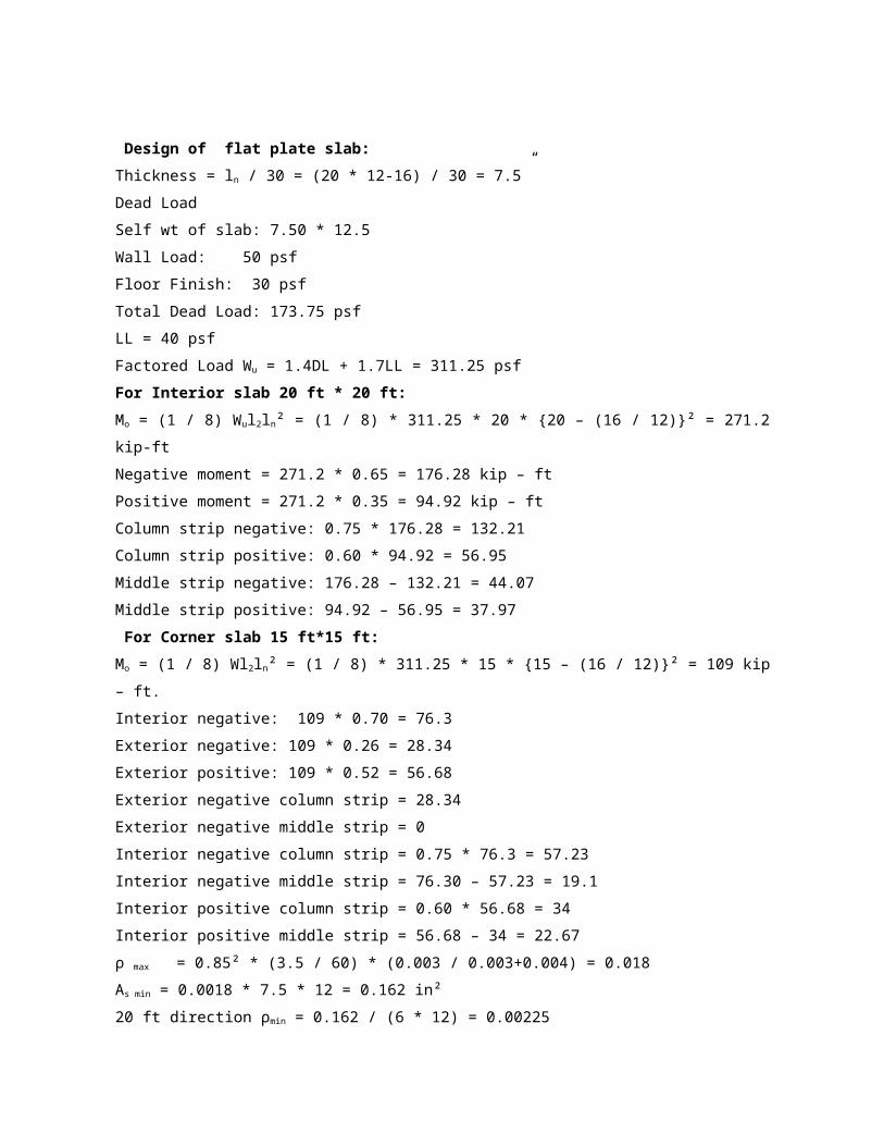
Design of flat plate slab:
Thickness = ln / 30 = (20 * 12-16) / 30 = 7.5”

Dead Load
Self wt of slab: 7.50 * 12.5
Wall Load: 50 psf
Floor Finish: 30 psf
Total Dead Load: 173.75 psf
LL = 40 psf
Factored Load Wu = 1.4DL + 1.7LL = 311.25 psf
For Interior slab 20 ft * 20 ft:
Mo = (1 / 8) Wul2ln² = (1 / 8) * 311.25 * 20 * {20 – (16 / 12)}² = 271.2 kip-ft
Negative moment = 271.2 * 0.65 = 176.28 kip – ft
Positive moment = 271.2 * 0.35 = 94.92 kip – ft
Column strip negative: 0.75 * 176.28 = 132.21
Column strip positive: 0.60 * 94.92 = 56.95
Middle strip negative: 176.28 – 132.21 = 44.07
Middle strip positive: 94.92 – 56.95 = 37.97
For Corner slab 15 ft*15 ft:
Mo = (1 / 8) Wl2ln² = (1 / 8) * 311.25 * 15 * {15 – (16 / 12)}² = 109 kip – ft.
Interior negative: 109 * 0.70 = 76.3
Exterior negative: 109 * 0.26 = 28.34
Exterior positive: 109 * 0.52 = 56.68
Exterior negative column strip = 28.34
Exterior negative middle strip = 0
Interior negative column strip = 0.75 * 76.3 = 57.23
Interior negative middle strip = 76.30 – 57.23 = 19.1
Interior positive column strip = 0.60 * 56.68 = 34
Interior positive middle strip = 56.68 – 34 = 22.67
ρ max = 0.85² * (3.5 / 60) * (0.003 / 0.003+0.004) = 0.018
As min = 0.0018 * 7.5 * 12 = 0.162 in²
20 ft direction ρmin = 0.162 / (6 * 12) = 0.00225
15 ft direction ρmin = 0.162 / (6.50 *12) = 0.00208
d² = Mo / [0.90 * 0.018 * 60000 *12{1 – (0.59 * 0.018 * 60 / 3.50)}]
d = √ (Mo / 9540.50)
d = √ (26.44*12000/9540.50)

d = 5.80 in.
For exterior middle slab 20 ft*15 ft:
Long direction:
Mo = [311.25 * 15 * (20-16 / 12) ²] / 8 = 203.35 ft-kip
Negative moment = 0.65 * 203.35 = 132.2 ft – kip
Positive moment = 0.35 * 203.35 = 71.2 ft – kip
Column strip negative moment: 0.75 * 132.20 = 99.15 ft – kip
Column strip positive moment: 0.60 * 71.20 = 42.7 ft – kip
Middle strip negative moment: 132.20 – 99.15 = 33.05 ft – kip
Middle strip positive moment: 71.20 – 42.70 = 28.5 ft – kip
Short direction:
Mo = [311.25 * 20 * (15 – 16 / 12)²] / 8 = 145.34 ft – kip
Interior negative moment = 0.70 * 145.34 = 101.74 ft – kip
Interior positive moment = 0.52*145.34 = 75.58 ft – kip
Exterior negative moment = 0.26 * 145.34 = 37.8 ft – kip
Exterior negative column strip: 37.80 * 1 = 37.8 ft – kip
Exterior negative middle strip: 0
Interior negative column strip: 101.74 * 0.75 = 76.31 ft-kip
Interior negative middle strip: 101.74 – 76.31 = 25.43 ft – kip
Positive column strip: 0.60 * 75.58 = 45.35 ft – kip
Positive middle strip: 0.40 * 75.58 = 30.23 ft – kip
The table below is showing reinforcement requirement for 15 ft *15 ft panel
Table 3.13: Design of slab reinforcement in 15 ft *15 ft panel
Strip type Moment type Strip width b in. Mu
Ft-kipEffective depth of the slab d inMu*12/b
The table below is showing reinforcement requirement for 20 ft * 20 ft panel
Table 3.14: Design of slab reinforcement in 20 ft *20 ft panel
Strip type Moment type Strip width b in. Mu
Ft-kipEffective depth of the slab d inMu*12/b
Ft-kip/ft
Steel density ρRequired steel area As=ρbd in²

The table below is showing reinforcement requirement for 15 ft * 20 ft panel
Table 3.15: Design of slab reinforcement in 15 ft *20 ft panel
Strip type Moment type Strip width b in. Mu
Ft-kipEffective depth of the slab d inMu*12/b
Ft-kip/ft
Steel density ρRequired steel area As=ρbd in²
The figures below is showing the reinforcement arrangement in slab in flat plate structure
Figure 3.4: Reinforcement arrangement in slab in flat plate structure (long direction).

Figure 3.5: Reinforcement arrangement in slab in flat plate structure (short direction).
Punching Shear Check:
For Column- C6, C7, C11, C13:
Maximum spacing = 7.50 * 20 = 15 in
Vu = 0.31125 [17.50*17.5 - (22 * 22 / 144)] = 94.27 kip
D / 2 = 6 / 2 = 3 in
bo = 4 (16+6) = 88
Since, βc < 2;
φVc = φ 4√fc’ * bod = 0.75 * 4√3500 * 0.08 * 6.50 = 101.55 kip
For Column- C1, C4, C10, C16:
Vu = 0.31125 [8.20 * 8.20 - (19 * 19 / 144)] = 20.20 kip
bo = 19+19 = 38
φVc = φ 4√fc’ * bod = 0.75 * 4√3500 * 38 * 6.50 = 43.84 kip
For Column – C2, C3, C5, C8, C9, C12, C14, C15:
Vu = 0.31125 [17.50 * 8.20 - (19 * 22 / 144)] = 44 kip
bo = 19 * 20 + 22 = 60
φVc = φ 4√fc’ * bod = 69.22 kip]
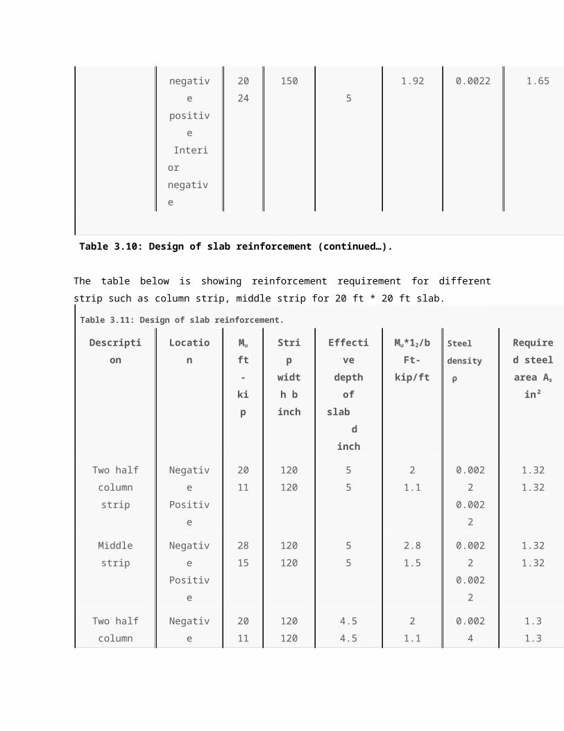
Figure 3.6: Distribution of total static moment M0 to critical section for positive and negative
bending.
Beam design
For beam design required data such as moment values, shears are taken from ETABS analysis
report shown in table – and designed various beams for various floors of the beam supported
structure.
Design of the beam: B 1, B3, B4, B6, B7, B9, B10, B11 ( at 6th story )
From load combination:
Maximum moment:
End section:
Negative moment = 42.61 k-ft
Mu = ф ρfy bd² (1- 0.59 ρfy / fc)
d² = Mu / фρfy bd (1- 0.59 ρfy / fc)
ρ max = 0 .75 ρb, ρb = 0.85 β1 f’c / fy * 87000 / (87000 + 60000)
= 0.85 * 0.85 * 3.50 / 60 * 87000 / (87000 + 60000) = 0.02494
ρ max = 0.75 * 0.02494 = 0.0187
d² = 42.61 * 12 / 0.90 * 0.0187 * 60 *10 (1- 0.59*0.0187*60/3.50)
d = 7.90, Clear cover = 2”, Total depth = 7.90+2 = 9.90 say, d = 10”
Provided Beam size = 10” * 10”, d = 10”- 20”= 8”
Main steel calculation:
As = Mu / φfy (d – a / 2) = 42.61 * 12 / 0.9 * 60 (8 – 1 / 2)
= 1.262 in², a = Asfy / 0.85fc bw, a = 1.262 * 60 / 0.85 * 3.5 * 10 = 2.545 in.
As = 42.61 * 12 / 0.9 * 60 (8 – 2.545 / 2) = 1.407 in²

a = 1.407 * 60 / 0.85 * 3.50 * 10 = 2.837 in.
As = 42.61 * 12 / 0.9 * 60 (8 – 2.837 / 2) = 1.438 in²
Use – 2 # 7 +1 # 5 bars
Main steel calculation:
Mid section:
As = Mu / φfy (d – a / 2) = 30.30 * 12 / 0.9 * 60 (8 – 1 / 2)
= 0.897 in², a = Asfy / 0.85fc bw, a = 0.897 * 60 / 0.85 * 3.5 *10 = 1.809 in
As = 30.30 * 12 / 0.9 * 60 (8 – 1.809 / 2) = 0.949 in²
a = 0.949 * 60 / 0.85 * 3.5 * 10 = 1.91 in.
As = 30.30 * 12 / 0.90 * 60 (8 – 1.91 / 2) = 0.955 in² use – 3 # 5 bars
Shear reinforcement design:
V= Vu – φVc
= 16.21 – (2 * 0.85√3500 * 10 * 8) / 1000 = 8.164 kip
4 √fc bw d = (4√3500 * 10 * 8) / 1000 = 16.09 kip
Vs < 4√fc bw d So, ok
Stirrup spacing:
1) Smax = Avfy / 50 bw = (2 * 0.11 * 60000) / 50 * 10 = 26.40”
2) Smax = d / 2 = 8 / 2 = 4”
3) Smax = 24”
4) S = φAvfyd / Vs = 0.85 * 2 * 0.11 * 60000 * 8 / (8.164 * 1000) = 10.99”
Use stirrups # 3 bar @ 4” c/c
Design of the beam: B2, B5, B8, B12 ( at 6th story )
From load combination:
Maximum moment:
End section:
Negative moment = 80.00 k – ft
Mu = ф ρfy bd² (1- 0.59 ρfy / fc)
d² = Mu / фρfy bd (1 – 0.59 ρfy / f’c)
ρ max = 0.75 ρb, ρb = 0.85 β1 fc / fy * 87000 / (87000 + 60000)
= 0.85 * 0.85 * 3.5 / 60 * 87000 / (87000 + 60000) = 0.02494
ρ max = 0.75 * 0.02494 = 0.0187
d² = 80.0 * 12 / 0.90 * 0.0187 * 60 * 10 (1- 0.59 * 0.0187 * 60 / 3.50)
d = 10.82, Clear cover = 2”, Total depth = 10.82 + 2 = 12.82. Say d = 15
Provided Beam size = 15” * 10”, d = 15”- 2”= 13”
Main steel calculation:
As = Mu / φfy (d – a / 2)
= 80.0 *12 / 0.9 * 60 (13 – 1 / 2)
= 1.422 in², a = Asfy / 0.85fc bw, a = 1.422 * 60 / 0.85 * 3.5 * 10 = 2.868 in
As = 80.0 * 12 / 0.90 * 60 (8 – 2.868 / 2) = 1.537 in²
a = 1.537 * 60 / 0.85 * 3.50 * 10 = 3.099 in.
As = 80.0 * 12 / 0.90 * 60 (8 – 3.099 / 2) = 1.552 in², use – 2 # 7 +2 # 5 bars
Main steel calculation:
Mid section:
As = Mu / φfy (d – a / 2)
= 57.29 * 12 / 0.90 * 60 (13 – 1 / 2)
= 1.018 in², a = Asfy / 0.85fc bw, a = 1.018 * 60 / 0.85 * 3.5 *10 = 2.053 in
As = 57.29 * 12 / 0.90 * 60 (13 – 2.053 / 2) = 1.063 in²
a = 1.063 * 60 / 0.85 * 3.50 * 10 = 2.143 in.
As = 57.29 * 12 / 0.90 * 60 (13 – 2.143 / 2) = 1.067 in² use – 4 # 5 bars
Shear reinforcement design:
Vs = Vu - φVc
= 24.14 – (2 * 0.85√3500 * 10 *13) / 1000 = 11.06 kip
4 √fc bw d = (4√3500 * 10 * 13) / 1000 = 30.763 kip
Vs < 4√fc bw d So, ok
Stirrup spacing:
1) Smax = Avfy / 50 bw = (2 * 0.11* 60000) / 50 * 10 = 26.40”
2) Smax = d / 2 = 13 / 2 = 6½”
3) Smax = 24”
4) S = φ Avfy d / Vs = 0.85 * 2 * 0.11 * 60000 * 13 / (11.06 * 1000) =13.1”
Use stirrups # 3 bar @ 6½” c/c
Design of the beam: B14, B17, B 20, B23 ( at 6th story )
From load combination:
Maximum moment at end section
Negative moment = 132.38 k – ft
Mu = ф ρfy bd² (1 – 0.59 ρfy / fc)
d² = Mu / (фρfy bd (1- 0.59 ρfy / fc)
ρ max = 0.75 ρb, ρb = 0.85 β1 fc / fy * 87000 / (87000 + 60000)
= 0.85 * 0.85 * 3.50 / 60 * 87000 / (87000 + 60000) = 0.02494

ρ max = 0.75 * 0.02494 = 0.0187
d² = 132.38 * 12 / 0.90 * 0.0187 * 60 * 10 (1-0.59 * 0.0187 * 60 / 3.50)
d = 13.92, Clear cover = 2”, Total depth = 13.92 + 2 = 15.92.92. Say, d = 18”
Provided Beam size = 18” * 10”, d = 18”- 2”= 16”
Main steel calculation:
As = Mu / φfy (d – a / 2)
= 132.38 * 12 / 0.90 * 60 (16 – 1 / 2)
= 1.897 in², a = Asfy / 0.85fc bw, a = 1.897 * 60 / 0.85 * 3.5 * 10 = 3.825 in
As = 132.38 * 12 / 0.90 * 6 (16 – 3.825 / 2) = 2.088 in²
a = 2.088 * 60 / 0.85 * 3.50 * 10 = 4.211 in.
As = 132.38 * 12 / 0.90 * 60 (16 – 4.211 / 2) = 2.117 in² use – 2 # 8 +2 # 5 bars
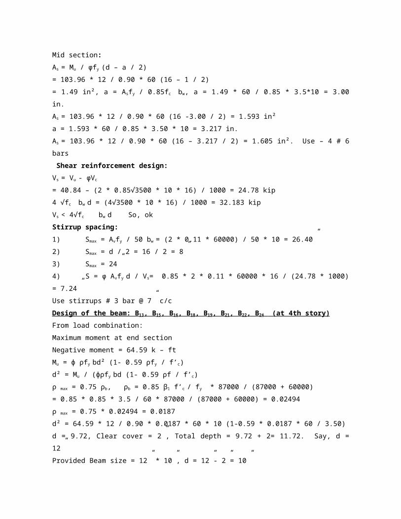
Main steel calculation:
Mid section:
As = Mu / φfy (d – a / 2)
= 103.96 * 12 / 0.90 * 60 (16 – 1 / 2)
= 1.49 in a = Asfy / 0.85fc, bw a = 1.49 * 60 / 0.85 * 3.5 *10 = 3.00 in.
As = 103.96 * 12 / 0.90 * 60 (16 – 3.00 / 2) = 1.593 in²
a = 1.593 * 60 / 0.85 * 3.50 * 10 = 3.217 in.
As = 103.96 *12 / 0.90 * 60 (16 – 3.217 / 2) = 1.605 in². Use – 2 # 6 +2 # 5 bars
Shear reinforcement design:
Vs = Vu - φVc
= 40.84 – (2 * 0.85√3500 * 10 * 16) / 1000 = 24.78 kip
4 √fc bw d = (4√3500 * 10 * 16) / 10 00 = 32.183 kip
Vs < 4√fc bw d. So, ok
Stirrup spacing:
1) Smax = Avfy / 50 bw = (2 * 0.11 * 60000) / 50 * 10 = 26.40”
2) Smax = d / 2 = 16 / 2 = 8”
3) Smax = 24”
4) S = φAvfy d / Vs = 0.85 * 2 * 0.11* 60000 *16 / (24.78 * 1000) = 7.24 ”
Use stirrups # 3 bar @ 7” c/c
Design of the beam: B13, B15, B16, B18, B19, B21, B22, B24 (at 6th story)
From load combination:
Maximum moment at end section
Negative moment = 64.59 k – ft

Mu = ф ρfy bd² (1- 0.59 ρfy / fc)
d² = Mu / (ф ρfy bd (1 – 0.59 ρfy / fc)
ρ max = 0 .75 ρb, ρb = 0.85 β1 fc / fy * 87000 / (87000 + 60000)
= 0.85 * 0.85 * 3.5 / 60 * 87000 / (87000 + 60000) = 0.02494
ρ max = 0.75 * 0.02494 = 0.0187
d² = 64.59 * 12 / 0.90 * 0.0187 * 60 * 10 (1- 0.59 * 0.018 * 60 / 3.50)
d = 9.72, Clear cover = 2”, Total depth = 9.72+2= 11.72. Say, d = 12”
Provided Beam size = 12” * 10”, d = 12”- 2” = 10”
Main steel calculation:
As = Mu / φfy (d – a / 2)
= 64.59 * 12 / 0.90 * 60 (10 – 1 / 2) = 1.51 in², a = Asfy / 0.85fc bw
a = 1.51 * 60 / 0.85 * 3.50 * 10 = 3.045 in
As = 64.59 * 12 / 0.90 * 60 (10 – 3.045 / 2) = 1.693 in²
a = 1.693 * 60 / 0.85 * 3.5 * 10 = 3.414 in.
As = 64.59 *12 / 0.90 * 60 (10 – 3.414 / 2) = 1.73 in² use – 2 # 7 +2 # 5 bars
Main steel calculation:
Mid section:
As = Mu / φfy (d – a / 2)
= 51.98 * 12 / 0.90 * 60 (10 – 1 / 2)
= 1.215 in², a = Asfy / 0.85fc, bw a = 1.215 * 60 / 0.85 * 3.5 * 10 = 2.450 in
As = 51.98*12 / 0.90 * 60 (10 – 2.45 / 2) = 1.316 in²
a = 1.316 * 60 / 0.85 * 3.50 * 10 = 2.609 in.
As = 51.98 * 12 / 0.90 * 60 (10 – 2.609 / 2) = 1.328 in² use – 2 # 6 +2 # 5 bars
Shear reinforcement design:
Vs = Vu - φVc
= 25.40 – (2 * 0.85√3500 * 10 * 10) / 1000 = 15.34 kip
4 √fc bw d = (4√3500 * 10 * 10) / 1000 = 23.66 kip
Vs < 4√fc bw d So, ok
Stirrup spacing:
1) Smax = Avfy / 50 bw = (2 * 0.11 * 60000) / 50 * 10 = 26.40”
2) Smax = d / 2 = 10 / 2 = 5”
3) Smax = 24”
4) S = φAvfy d / Vs = 0.85 * 2 * 0.1 1* 60000 * 10 / (15.34 * 1000) = 7.31 ”
Use stirrups # 3 bar @ 5” c/c

Design of the beam: B1, B3, B4, B6, B7, B9, B10, B11 ( at 5th story )
From load combination:
Maximum moment at end section
Negative moment = 42.61 k – ft
Mu = ф ρfy bd² (1 – 0.59 ρfy / fc)
d² = Mu / ф ρfy bd (1- 0.59 ρfy / fc)
ρ max = 0.75 ρb ,
ρb = 0.85 β1 fc / fy * 87000 / (87000 + 60000)
= 0.85 * 0.85 * 3.5 / 60 * 87000 / (87000 + 60000) = 0.02494
ρmax = 0.75 * 0.02494 = 0.0187
d² = 42.61 * 12 / 0.90 * 0.0187 * 60 * 10 (1- 0.59 * 0.0187 * 60/3.50)
d = 7.90, Clear cover = 2”, Total depth = 7.90 + 2 = 9.90. Say, d = 10”
Provided Beam size = 10” * 10”, d = 10”- 2”= 8”
Main steel calculation:
As = Mu / φfy (d – a / 2)
= 42.61 * 12 / 0.90 * 60 (8 – 1 / 2) = 1.262 in², a = Asfy / 0.85fc bw,
a = 1.262 * 60 / 0.85 * 3.50 * 10 = 2.545 in
As = 42.61 * 12 / 0.90 * 60 (8 – 2.545 / 2)
As = 1.407 in²
a = 1.407 * 60 / 0.85 * 3.50 * 10 = 2.837 in.
As = 42.61 * 12 / 0.90 * 60 (8 – 2.837 / 2) = 1.438 in². Use – 2 # 7 +1 # 5 bars
Main steel calculation:
Mid section:
As = Mu / φfy (d – a / 2)
= 30.30 * 12 / 0.90 * 60 (8 – 1 / 2) = 0.897 in², a = Asfy / 0.85fc bw,
a = 0.897 * 60 / 0.85 * 3.50 * 10 =1.809 in.
As = 30.30 * 12 / 0.9 * 60 (8 – 1.809 / 2) = 0.949 in²
a = 0.949 * 60 / 0.85 * 3.50 * 10 = 1.91 in.
As = 30.30 * 12 / 0.90 * 60 (8 – 1.91 / 2) = 0.955 in². Use – 3 # 5 bars
Shear reinforcement design:
Vs = Vu - φVc
= 16.21 – (2 * 0.85√3500 * 10 * 8) / 1000 = 8.164 kip
4φ √fc bw d = (4 * 0.85√3500 *10 * 8) / 1000 = 16.09 kip
Vs < 4√fc bw d So, ok

Stirrup spacing:
1) Smax = Avfy / 50 bw = (2*.11*60000) / 50 * 10 = 26.40”
2) Smax = d / 2 = 8 / 2 = 4”
3) Smax = 24”
4) S = φ Avfy d / Vs = 0.85 * 2 * 0.11 * 60000 * 8 / (8.164 * 1000) = 10.99”
Use stirrups # 3 bar @ 4” c/c
Design of the beam: B2, B5, B8, B12 ( at 5th story )
From load combination:
Maximum moment:
End section:
Negative moment = 80.00 k – ft
Mu = ф ρfy bd² (1- 0.59 ρfy / fc)
d² = Mu / ф ρfy bd (1- 0.59 ρfy / fc)
ρ max = 0.75 ρb , ρb = 0.85 β1 fc / fy * 87000 / (87000 + 60000)
= 0.85 * 0.85 * 3.50 / 60 * 87000 / (87000 + 60000) = 0.02494
ρ max = 0.75 * 0.02494 = 0.0187
d² = 80.0 * 12 / 0.90 * 0.0187 * 60 * 10 (1- 0.59 * 0.0187 * 60 / 3.50)
d = 10.82, Clear cover = 2”, Total depth = 10.82 + 2 = 12.82. Say, d = 15
Provided Beam size = 15” * 10”, d = 15”- 2”= 13”
Main steel calculation:
As = Mu / φfy (d – a / 2)
= 80.0 * 12 / 0.90 * 60 (13 – 1 / 2)
= 1.422 in², a = Asfy / 0.85fc bw,
a = 1.422 * 60 / 0.85 * 3.50 * 10 = 2.868 in
As = 80.0 * 12 / 0.90 * 60 (8 – 2.868 / 2) = 1.537 in²
a = 1.537 * 60 / 0.85 * 3.50 * 10 = 3.099 in.
As = 80.0 * 12 / 0.90 * 60 (8 – 3.099 / 2) = 1.552 in². Use – 2 # 7 +2 # 5 bars
Main steel calculation:
Mid section:
As = Mu / φfy (d – a / 2)
= 57.29 * 12 / 0.90 * 60 (13 – 1 / 2) = 1.018 in², a = Asfy / 0.85fc bw,
a = 1.018 * 60 / 0.85 * 3.5*10 = 2.053 in.
As = 57.29 * 12 / 0.90 * 60 (13- 2.053 / 2) = 1.063 in²
a = 1.063 * 60 / 0.85 * 3.50 * 10 = 2.143 in.

As = 57.29 * 12 / 0.90 * 60 (13 – 2.143 / 2) = 1.067 in². Use – 4 # 5 bars
Shear reinforcement design:
Vs = Vu - φVc
= 24.14 – (2 * 0.85√3500 * 10 * 13) / 1000 = 11.06 kip
4φ √fc bw d = (4 * 0.85√3500 * 10 * 13 / 1000 = 30.763 kip
Vs < 4√fc bw d So, ok
Stirrup spacing:
1) Smax = Avfy / 50 bw = (2 * 0.11 * 60000) / 50 * 10 = 26.40”
2) Smax = d / 2 = 13 / 2 = 6½”
3) Smax = 24”
4) S = φ Avfy d / Vs = 0.85 * 2 * 0.11 * 60000 * 13 / (11.06 * 1000) = 13.1”
Use stirrups # 3 bar @ 6½” c/c
Design of the beam: B14, B17, B20, B23 ( at 5th story )
From load combination:
Maximum moment at end section
Negative moment = 132.38 k-ft
Mu = ф ρfy bd² (1 – 0.59 ρfy / f’c)
d² = Mu / (ф ρfy bd (1- 0.59 ρfy / fc)
ρ max = 0.75 ρb, ρb = 0.85 β1 f’c / fy * 87000 / (87000 + 60000)
= 0.85 * 0.85 * 3.5 / 60 * 87000 / (87000 + 60000) = 0.02494
ρ max = 0.75 * 0.02494 = 0.0187
d² = 132.38 * 12 / 0.90 * 0.0187 * 60 * 10 (1- 0.59 * 0.0187 * 60 / 3.50)
= 13.92, Clear cover = 2”, Total depth = 13.92 + 2 = 15.92. Say, d = 18”
Provided Beam size = 18” * 10”, d = 18”- 2”= 16”
Main steel calculation:
As = Mu / φfy (d – a / 2)
= 132.38 * 12 / 0.90 * 60 (16 – 1 / 2)
= 1.897 in², a = Asfy / 0.85fc bw, a = 1.897 * 60 / 0.85 * 3.5 * 10 = 3.825 in.
As = 132.38 * 12 / 0.90 * 60 (16 – 3.825 / 2) = 2.088 in²
a = 2.088 * 60 / 0.85 * 3.50 * 10 = 4.211 in.
As = 132.38 * 12 / 0.90 * 60 (16 – 4.211 / 2) = 2.117 in². Use – 2 # 7 +3 # 5 bars
Main steel calculation:
Mid section:
As = Mu / φfy (d – a / 2)

= 103.96 * 12 / 0.90 * 60 (16 – 1 / 2)
= 1.49 in², a = Asfy / 0.85fc bw, a = 1.49 * 60 / 0.85 * 3.5*10 = 3.00 in.
As = 103.96 * 12 / 0.90 * 60 (16 -3.00 / 2) = 1.593 in²
a = 1.593 * 60 / 0.85 * 3.50 * 10 = 3.217 in.
As = 103.96 * 12 / 0.90 * 60 (16 – 3.217 / 2) = 1.605 in². Use – 4 # 6 bars
Shear reinforcement design:
Vs = Vu - φVc
= 40.84 – (2 * 0.85√3500 * 10 * 16) / 1000 = 24.78 kip
4 √fc bw d = (4√3500 * 10 * 16) / 1000 = 32.183 kip
Vs < 4√fc bw d So, ok
Stirrup spacing:
1) Smax = Avfy / 50 bw = (2 * 0.11 * 60000) / 50 * 10 = 26.40”
2) Smax = d / 2 = 16 / 2 = 8”
3) Smax = 24”
4) S = φ Avfy d / Vs= 0.85 * 2 * 0.11 * 60000 * 16 / (24.78 * 1000) = 7.24”
Use stirrups # 3 bar @ 7” c/c
Design of the beam: B13, B15, B16, B18, B19, B21, B22, B24 (at 4th story)
From load combination:
Maximum moment at end section
Negative moment = 64.59 k – ft
Mu = ф ρfy bd² (1- 0.59 ρfy / f’c)
d² = Mu / (фρfy bd (1- 0.59 ρf / f’c)
ρ max = 0.75 ρb, ρb = 0.85 β1 f’c / fy * 87000 / (87000 + 60000)
= 0.85 * 0.85 * 3.5 / 60 * 87000 / (87000 + 60000) = 0.02494
ρ max = 0.75 * 0.02494 = 0.0187
d² = 64.59 * 12 / 0.90 * 0.0187 * 60 * 10 (1-0.59 * 0.0187 * 60 / 3.50)
d = 9.72, Clear cover = 2”, Total depth = 9.72 + 2= 11.72. Say, d = 12”
Provided Beam size = 12” * 10”, d = 12”- 2”= 10”
Main steel calculation:
As = Mu / φfy (d – a / 2)
= 64.59 * 12 / 0.90 * 60 (10 – 1 / 2) = 1.51 in², a = Asfy / 0.85f’c bw
a = 1.51 * 60 / 0.85 * 3.50 * 10 = 3.045
As = 64.59 * 12 / 0.90 * 60 (10 – 3.045 / 2) = 1.693 in²
a = 1.693 * 60 / 0.85 * 3.5 * 10 = 3.414 in.

As = 64.59 * 12 / 0.90 * 60 (10 – 3.414 / 2) = 1.73 in². Use – 2 # 7 +2 # 5 bars
Main steel calculation:
Mid section:
As = Mu / φfy (d – a / 2)
= 51.98 * 12 / 0.90 * 60 (10 – 1 / 2) = 1.215 in², a = Asfy / 0.85f’c bw
a = 1.215 * 60 / 0.85 * 3.50 * 10 = 2.450 in.
As = 51.98 * 12 / 0.90 * 60 (10 – 2.45 / 2) = 1.316 in²
a = 1.316 * 60 / 0.85 * 3.50 * 10 = 2.609 in.
As = 51.98 * 12 / 0.90 * 60 (10 – 2.609 / 2) = 1.328 in². Use – 2 # 6 +2 # 5 bars
Shear reinforcement design:
Vs = Vu - φVc
= 25.40 – (2 * 0.85√3500 * 10 * 10) / 1000 = 15.34 kip
4 √fc bw d = (4√3500 * 10 * 10) / 1000 = 23.66 kip
Vs < 4√fc bw d So, ok
Stirrup spacing:
1) Smax = Avfy / 50 bw = (2 * 0.11 * 60000) / 50 * 10 = 26.40”
2) Smax = d / 2 = 10 / 2 = 5”
3) Smax = 24”
4) S = φ Avfy d / Vs = 0.85 * 2 * 0.11 * 60000 * 10 / (15.34*1000) = 7.31 ”
Use stirrups # 3 bar @ 5” c/c
Design of the beam: B1, B3,B4, B6, B7, B 9, B10, B11 ( at 4th story )
From load combination:
Maximum moment:
End section:
Negative moment = 87.25 k – ft
Mu = ф ρfy bd² (1- 0.59 ρfy / fc)
d² = Mu/ фρfy bd (1- 0.59 ρfy / fc)
ρ max = 0 .75 ρb, ρb = 0.85 β1 f’c / fy * 87000 / (87000 + 60000)
= 0.85 * 0.85 * 3.5 / 60 * 87000 / (87000 + 60000) = 0.02494
ρ max = 0.75 * 0.02494 = 0.0187
d² = 87.25 * 12 / 0.90 * 0.0187 * 60 * 10 (1- 0.59 * 0.0187 * 60 / 3.50)
d = 11.29, Clear cover = 2”, Total depth = 11.29 + 2= 13.29. Say, d = 15”
Provided Beam size = 15” * 10”, d = 15”- 2”= 13”
Main steel calculation:

As = Mu / φfy (d – a / 2)
= 87.25 * 12 / 0.90 * 60 (13 – 1 / 2) = 1.551 in², a = Asfy / 0.85fc bw
a = 1.551 * 60 / 0.85 * 3.50 * 10 = 3.128 in.
As = 87.25 * 12/0.90 * 60 (13 – 3.128 / 2) = 1.695 in²
a = 1.695 * 60 / 0.85 * 3.50 * 10= 3.418 in.
As = 87.25 * 12 / 0.90 * 60 (10 – 3.418 / 2) = 1.717 in². Use – 2 # 7 + 2 # 5 bars
Main steel calculation:
Mid section:
As = Mu / φfy (d – a / 2)
= 35.0 * 12 / 0.90 * 60 (13 – 1 / 2) = 0.622 in², a = Asfy / 0.85f’c bw
a = 0.622 * 60 / 0.85 * 3.50 * 10 = 1.254 in.
As = 35.00 * 12 / 0.90 * 60 (13 – 1.254 / 2) = 0.628 in²
a = 0.628 * 60 / 0.85 * 3.50 * 10 = 1.266 in.
As = 35.0 * 12 / 0.90 * 60 (13 – 1.266/2) = 0.63 in². Use – 2 # 6 bars
Shear reinforcement design:
Vs = Vu - φVc
= 22.23 – (2 * 0.85√3500 * 10 * 13) / 1000 = 9.15 kip
4 √fc bw d = (4√3500 * 10 * 13) /1000 = 30.76 kip
Vs < 4√fc bw d So, ok
Stirrup spacing:
1) Smax = Avfy / 50 bw = (2 * 0.11* 60000) / 50 * 10 = 26.40”
2) Smax = d / 2 = 13 / 2 = 6½”
3) Sma = 24”
4) S = φ Avfy d / Vs = 0.85 * 2 * 0.11 * 60000 * 13 / (9.15 * 1000) = 15.94”
Use stirrups # 3 bar @ 6½” c/c
Design of the beam: B2, B5, B8, B12 ( at 4th story )
From load combination:
Maximum moment:
End section:
Negative moment = 108.93 k-ft
Mu = ф ρfy bd² (1- 0.59 ρfy / fc)
d² = Mu / фρfy bd (1- 0.59 ρfy / fc)
ρ max = 0.75 ρb, ρb = 0.85 β1 fc / fy * 87000 / (87000 + 60000)
= 0.85 * 0.85 * 3.5 / 60 * 87000 / (87000 + 60000) = 0.02494

ρ max = 0.75 * 0.02494 = 0.0187
d² = 108.93 * 12 / 0.90 * 0.0187 * 60 * 10(1- 0.59 * 0.0187 * 60 / 3.50)
d = 12.63, Clear cover = 2”, Total depth = 12.63 + 2 = 14.63. Say, d = 15”
Provided Beam size = 15” * 10”, d = 15”- 2”= 13”
Main steel calculation:
As = Mu / φfy (d – a / 2)
= 108.93 * 12 / 0.90 * 60 (13 – 1 / 2) = 1.936 in², a = Asfy / 0.85fc bw,
a = 1.936 * 60 / 0.85 * 3.50 * 10 = 3.904 in.
As = 108.93 * 12 / 0.90 * 60 (13 – 3.904 / 2) = 1.867 in²
a = 1.897 * 60 / 0.85 * 3.50 * 10 = 3.765 in.
As = 108.93 * 12 / 0.90 * 60 (13 – 3.765 / 2) = 2.177 in². Use – 2 # 8 +2 # 5 bars
Main steel calculation:
Mid section:
As = Mu / φfy (d – a / 2)
= 59.56 * 12 / 0.90 * 60 (13 – 1 / 2) = 1.058 in², a = Asfy / 0.85fc bw,
a = 1.058 * 60 / 0.85 * 3.50 * 10 = 2.133 in.
As = 59.56 * 12 / 0.90 * 60 (13 – 2.133 / 2) = 1.108 in²
a = 1.108 * 60 / 0.85 * 3.5 * 10 = 2.234 in.
As = 59.56 * 12 / 0.90 * 60 (13 – 2.234 / 2) = 1.113in². Use – 4 # 5 bars
Shear reinforcement design:
Vs = Vu - φVc
= 26.90 – (2 * 0.85√3500 * 10 * 13) / 1000 = 13.825 kip
4 √fc bw d = (4√3500 * 10 * 13) / 1000 = 30.763 kip
Vs < 4√fc bw d So, ok
Stirrups Spacing:
1) Smax = Avfy / 50 bw = (2 * 0.11 * 60000) / 50 * 10 = 26.40”
2) Smax = d / 2 = 13 / 2 = 6½”
3) Smax = 24”
4) S = φ Avfyd / Vs = 0.85 * 2 * 0.11 * 60000 * 13 / (13.825 * 1000) = 10.55”
Use stirrups # 3 bar @ 6½” c/c
Design of the beam: B14, B17, B20, B23 (at 4th story)
From load combination:
Maximum Moment:
End section:

Negative moment = 164.32 k-ft
Mu = ф ρfy bd² (1 – 0.59 ρfy / fc)
d² = Mu / (ф ρfy bd (1- 0.59 ρfy / fc)
ρ max = 0.75 ρb, ρb = 0.85 β1 fc / fy * 87000 / (87000 + 60000)
= 0.85 * 0.85 * 3.5 / 60 * 87000 / (87000 + 60000) = 0.02494
ρmax = 0.75 * 0.02494 = 0.0187
d² = 164.32 *12 / 0.90 * 0.0187 * 60 * 12 (1 – 0.59 * 0.0187 * 60 / 3.50)
d = 14.16, Clear cover = 2”, Total depth = 14.16 + 2 = 16.16. Say, d = 18”
Provided Beam size = 18” * 10”, d = 18”- 2”= 16”
Main steel calculation:
As = Mu / φfy (d – a / 2)
= 164.32 * 1 / 0.90 * 60 (16 – 1 / 2) = 2.355 in², a = Asfy / 0.85fc bw,
a = 2.355 * 60 / 0.85 * 3.50 * 12 = 3.957 in.
As = 164.32 * 12 / 0.90 * 60 (16 – 3.597 / 2) = 2.604 in²
a = 2.604 * 60 / 0.85 * 3.50 * 10 = 4.376 in.
As = 164.32 * 12 / 0.90 * 60 (16 – 4.376 / 2) = 2.643 in². Use – 2 # 9 +2 # 5 bars
Main steel calculation:
Mid section:
As = Mu / φfy (d – a / 2)
= 103.66 * 12 / 0.90 * 60 (16 – 1 / 2) = 1.49 in², a = Asfy / 0.85fc bw,
a = 1.49 * 60 / 0.85 * 3.5 * 10 = 3.00 in.
As = 103.66 * 12 / 0.90 * 60 (16 – 3.00 / 2) = 1.59 in²
a = 1.59 * 60 / 0.85 * 3.50 * 10 = 3.206 in.
As = 103.66 * 12 / 0.90 * 60 (16 – 3.206 / 2) = 1.60 in². Use – 2 # 7 +2 # 5 bars
Shear reinforcement design:
Vs = Vu - φVc
= 40.84 – (2 * 0.85√3500 * 10 * 16) / 1000 = 24.78 kip
4 √fc bw d = (4√3500 * 10 * 16) / 1000 = 32.183 kip
Vs < 4√fc bw d So, ok
Stirrup spacing:
1) Smax = Avfy / 50 bw = (2 * 0.11 * 60000) / 50 * 10 = 26.40”
2) Smax = d / 2 = 16 / 2 = 8”
3) Smax = 24”
4) S = φ Avfy d / Vs= 0.85 * 2 * 0.11 * 60000 * 16 / (24.78 * 1000) = 7.24”

Use stirrups # 3 bar @ 7” c/c
Design of the beam: B13, B15, B16, B18, B19, B21, B22, B24 (at 4th story)
From load combination:
Maximum moment at end section
Negative moment = 64.59 k – ft
Mu = ф ρfy bd² (1- 0.59 ρfy / f’c)
d² = Mu / (фρfy bd (1- 0.59 ρf / f’c)
ρ max = 0.75 ρb, ρb = 0.85 β1 f’c / fy * 87000 / (87000 + 60000)
= 0.85 * 0.85 * 3.5 / 60 * 87000 / (87000 + 60000) = 0.02494
ρ max = 0.75 * 0.02494 = 0.0187
d² = 64.59 * 12 / 0.90 * 0.0187 * 60 * 10 (1-0.59 * 0.0187 * 60 / 3.50)
d = 9.72, Clear cover = 2”, Total depth = 9.72 + 2= 11.72. Say, d = 12”
Provided Beam size = 12” * 10”, d = 12”- 2”= 10”
Main steel calculation:
As = Mu / φfy (d – a / 2)
= 64.59 * 12 / 0.90 * 60 (10 – 1 / 2) = 1.51 in², a = Asfy / 0.85f’c bw
a = 1.51 * 60 / 0.85 * 3.50 * 10 = 3.045
As = 64.59 * 12 / 0.90 * 60 (10 – 3.045 / 2) = 1.693 in²
a = 1.693 * 60 / 0.85 * 3.5 * 10 = 3.414 in.
As = 64.59 * 12 / 0.90 * 60 (10 – 3.414 / 2) = 1.73 in². Use – 2 # 7 +2 # 5 bars
Main steel calculation:
Mid section:
As = Mu / φfy (d – a / 2)
= 51.98 * 12 / 0.90 * 60 (10 – 1 / 2) = 1.215 in², a = Asfy / 0.85f’c bw
a = 1.215 * 60 / 0.85 * 3.50 * 10 = 2.450 in.
As = 51.98 * 12 / 0.90 * 60 (10 – 2.45 / 2) = 1.316 in²
a = 1.316 * 60 / 0.85 * 3.50 * 10 = 2.609 in.
As = 51.98 * 12 / 0.90 * 60 (10 – 2.609 / 2) = 1.328 in². Use – 2 # 6 +2 # 5 bars
Shear reinforcement design:
Vs = Vu - φVc
= 25.40 – (2 * 0.85√3500 * 10 * 10) / 1000 = 15.34 kip
4 √fc bw d = (4√3500 * 10 * 10) / 1000 = 23.66 kip
Vs < 4√fc bw d So, ok
Stirrup spacing:

1) Smax = Avfy / 50 bw = (2 * 0.11 * 60000) / 50 * 10 = 26.40”
2) Smax = d / 2 = 10 / 2 = 5”
3) Smax = 24”
4) S = φ Avfy d / Vs = 0.85 * 2 * 0.11 * 60000 * 10 / (15.34*1000) = 7.31 ”
Use stirrups # 3 bar @ 5” c/c
Design of the beam: B1, B3,B4, B6, B7, B 9, B10, B11 ( at 4th story )
From load combination:
Maximum moment:
End section:
Negative moment = 87.25 k – ft
Mu = ф ρfy bd² (1- 0.59 ρfy / fc)
d² = Mu/ фρfy bd (1- 0.59 ρfy / fc)
ρ max = 0 .75 ρb, ρb = 0.85 β1 f’c / fy * 87000 / (87000 + 60000)
= 0.85 * 0.85 * 3.5 / 60 * 87000 / (87000 + 60000) = 0.02494
ρ max = 0.75 * 0.02494 = 0.0187
d² = 87.25 * 12 / 0.90 * 0.0187 * 60 * 10 (1- 0.59 * 0.0187 * 60 / 3.50)
d = 11.29, Clear cover = 2”, Total depth = 11.29 + 2= 13.29. Say, d = 15”
Provided Beam size = 15” * 10”, d = 15”- 2”= 13”
Main steel calculation:
As = Mu / φfy (d – a / 2)
= 87.25 * 12 / 0.90 * 60 (13 – 1 / 2) = 1.551 in², a = Asfy / 0.85fc bw
a = 1.551 * 60 / 0.85 * 3.50 * 10 = 3.128 in.
As = 87.25 * 12/0.90 * 60 (13 – 3.128 / 2) = 1.695 in²
a = 1.695 * 60 / 0.85 * 3.50 * 10= 3.418 in.
As = 87.25 * 12 / 0.90 * 60 (10 – 3.418 / 2) = 1.717 in². Use – 2 # 7 + 2 # 5 bars
Main steel calculation:
Mid section:
As = Mu / φfy (d – a / 2)
= 35.0 * 12 / 0.90 * 60 (13 – 1 / 2) = 0.622 in², a = Asfy / 0.85f’c bw
a = 0.622 * 60 / 0.85 * 3.50 * 10 = 1.254 in.
As = 35.00 * 12 / 0.90 * 60 (13 – 1.254 / 2) = 0.628 in²
a = 0.628 * 60 / 0.85 * 3.50 * 10 = 1.266 in.
As = 35.0 * 12 / 0.90 * 60 (13 – 1.266/2) = 0.63 in². Use – 2 # 6 bars
Shear reinforcement design:

Vs = Vu - φVc
= 22.23 – (2 * 0.85√3500 * 10 * 13) / 1000 = 9.15 kip
4 √fc bw d = (4√3500 * 10 * 13) /1000 = 30.76 kip
Vs < 4√fc bw d So, ok
Stirrup spacing:
1) Smax = Avfy / 50 bw = (2 * 0.11* 60000) / 50 * 10 = 26.40”
2) Smax = d / 2 = 13 / 2 = 6½”
3) Sma = 24”
4) S = φ Avfy d / Vs = 0.85 * 2 * 0.11 * 60000 * 13 / (9.15 * 1000) = 15.94”
Use stirrups # 3 bar @ 6½” c/c
Design of the beam: B2, B5, B8, B12 ( at 4th story )
From load combination:
Maximum moment:
End section:
Negative moment = 108.93 k-ft
Mu = ф ρfy bd² (1- 0.59 ρfy / fc)
d² = Mu / фρfy bd (1- 0.59 ρfy / fc)
ρ max = 0.75 ρb, ρb = 0.85 β1 fc / fy * 87000 / (87000 + 60000)
= 0.85 * 0.85 * 3.5 / 60 * 87000 / (87000 + 60000) = 0.02494
ρ max = 0.75 * 0.02494 = 0.0187
d² = 108.93 * 12 / 0.90 * 0.0187 * 60 * 10(1- 0.59 * 0.0187 * 60 / 3.50)
d = 12.63, Clear cover = 2”, Total depth = 12.63 + 2 = 14.63. Say, d = 15”
Provided Beam size = 15” * 10”, d = 15”- 2”= 13”
Main steel calculation:
As = Mu / φfy (d – a / 2)
= 108.93 * 12 / 0.90 * 60 (13 – 1 / 2) = 1.936 in², a = Asfy / 0.85fc bw,
a = 1.936 * 60 / 0.85 * 3.50 * 10 = 3.904 in.
As = 108.93 * 12 / 0.90 * 60 (13 – 3.904 / 2) = 1.867 in²
a = 1.897 * 60 / 0.85 * 3.50 * 10 = 3.765 in.
As = 108.93 * 12 / 0.90 * 60 (13 – 3.765 / 2) = 2.177 in². Use – 2 # 8 +2 # 5 bars
Main steel calculation:
Mid section:
As = Mu / φfy (d – a / 2)
= 59.56 * 12 / 0.90 * 60 (13 – 1 / 2) = 1.058 in², a = Asfy / 0.85fc bw,
a = 1.058 * 60 / 0.85 * 3.50 * 10 = 2.133 in.
As = 59.56 * 12 / 0.90 * 60 (13 – 2.133 / 2) = 1.108 in²
a = 1.108 * 60 / 0.85 * 3.5 * 10 = 2.234 in.
As = 59.56 * 12 / 0.90 * 60 (13 – 2.234 / 2) = 1.113in². Use – 4 # 5 bars
Shear reinforcement design:
Vs = Vu - φVc
= 26.90 – (2 * 0.85√3500 * 10 * 13) / 1000 = 13.825 kip
4 √fc bw d = (4√3500 * 10 * 13) / 1000 = 30.763 kip
Vs < 4√fc bw d So, ok
Stirrups Spacing:
1) Smax = Avfy / 50 bw = (2 * 0.11 * 60000) / 50 * 10 = 26.40”
2) Smax = d / 2 = 13 / 2 = 6½”
3) Smax = 24”
4) S = φ Avfyd / Vs = 0.85 * 2 * 0.11 * 60000 * 13 / (13.825 * 1000) = 10.55”
Use stirrups # 3 bar @ 6½” c/c
Design of the beam: B14, B17, B20, B23 (at 4th story)
From load combination:
Maximum Moment:
End section:
Negative moment = 164.32 k-ft
Mu = ф ρfy bd² (1 – 0.59 ρfy / fc)
d² = Mu / (ф ρfy bd (1- 0.59 ρfy / fc)
ρ max = 0.75 ρb, ρb = 0.85 β1 fc / fy * 87000 / (87000 + 60000)
= 0.85 * 0.85 * 3.5 / 60 * 87000 / (87000 + 60000) = 0.02494
ρmax = 0.75 * 0.02494 = 0.0187
d² = 164.32 *12 / 0.90 * 0.0187 * 60 * 12 (1 – 0.59 * 0.0187 * 60 / 3.50)
d = 14.16, Clear cover = 2”, Total depth = 14.16 + 2 = 16.16. Say, d = 18”
Provided Beam size = 18” * 10”, d = 18”- 2”= 16”
Main steel calculation:
As = Mu / φfy (d – a / 2)
= 164.32 * 1 / 0.90 * 60 (16 – 1 / 2) = 2.355 in², a = Asfy / 0.85fc bw,
a = 2.355 * 60 / 0.85 * 3.50 * 12 = 3.957 in.
As = 164.32 * 12 / 0.90 * 60 (16 – 3.597 / 2) = 2.604 in²
a = 2.604 * 60 / 0.85 * 3.50 * 10 = 4.376 in.

As = 164.32 * 12 / 0.90 * 60 (16 – 4.376 / 2) = 2.643 in². Use – 2 # 9 +2 # 5 bars
Main steel calculation:
Mid section:
As = Mu / φfy (d – a / 2)
= 103.66 * 12 / 0.90 * 60 (16 – 1 / 2) = 1.49 in², a = Asfy / 0.85fc bw,
a = 1.49 * 60 / 0.85 * 3.5 * 10 = 3.00 in.
As = 103.66 * 12 / 0.90 * 60 (16 – 3.00 / 2) = 1.59 in²
a = 1.59 * 60 / 0.85 * 3.50 * 10 = 3.206 in.
As = 103.66 * 12 / 0.90 * 60 (16 – 3.206 / 2) = 1.60 in². Use – 2 # 7 +2 # 5 bars
Shear reinforcement design:
Vs = Vu - φVc
= 43.60 – (2 * 0.85√3500 * 10 * 16) / 1000 = 24.28 kip
4 √fc bw d = (4√3500 * 12 * 16) / 1000 = 45.435 kip
Vs < 4√fc bw d So, ok
Stirrup spacing:
1) Smax = Avfy / 50 bw = (2 * 0.11 * 60000) / 50 * 10 = 26.40”
2) Smax = d / 2 = 16 / 2 = 8”
3) Smax = 24”
4) S = φAvfy d / Vs = 0.85 * 2 * .11 * 60000 * 16 / (24.28 * 1000) = 7.39 ”
Use stirrups # 3 bar @ 7” c/c
Design of the beam: B13, B15, B16, B18, B19, B21, B22, B 24 (at 4th story)
From load combination:
Maximum moment at end section
Negative moment = 115.36 k – ft
Mu = ф ρfy bd² (1- 0.59 ρfy / fc)
d² = Mu / (ф ρfy bd (1- 0.59 ρf / fc)
ρ max = 0.75 ρb, ρb = 0.85 β1 fc / fy * 87000 / (87000 + 60000)
= 0.85 * 0.85 * 3.5 / 60 * 87000 / (87000 + 60000) = 0.02494
ρ max = 0.75 * 0.02494 = 0.0187
d² = 115.36 * 12 / 0.90 * 0.0187 * 60 * 10 (1 – 0.59 * 0.0187 * 60 / 3.50)
d = 13.0, Clear cover = 2”, Total depth = 13 + 2 = 15.0. Say, d = 15”
Provided Beam size = 15” * 10”, d = 15”- 2”= 13”
Main steel calculation:
As = Mu / φfy (d – a / 2)

= 115.36 * 12 / 0.90 * 60 (13 – 1 / 2) = 2.05 in², a = Asfy / 0.85fc bw.
a = 2.05 * 60 / 0.85 * 3.50 * 10 = 4.134 in
As = 115.36 * 12 / 0.90 * 60 (13 – 4.134 / 2) = 2.344 in²
a = 2.344 * 60 / 0.85 * 3.5 * 10 = 4.727 in.
As = 115.36 * 12 / 0.90 * 60 (13 – 4.727 / 2) = 2.41 in². Use – 2 # 8 +2 # 6 bars
Main steel calculation:
Mid section:
As = Mu / φfy (d – a / 2)
= 48.69 * 12 / 0.90 * 60 (13 – 1 / 2) = 0.865 in², a = Asfy / 0.85fc bw,
a = 0.865 * 60 / 0.85 * 3.50 * 10 = 1.744 in
As = 48.69 * 12 / 0.90 * 60 (13-1.744/2) = 0.892 in²
a = 0.892 * 60 / 0.85 * 3.50 * 10 = 1.798 in.
As = 48.69 * 12 / 0.90 * 60 (13 – 1.798 / 2) = 0.894 in². Use – 3 # 5 bars
Shear reinforcement design:
Vs = Vu - φVc
= 32.18 – (2 * 0.85√3500 * 10 * 13) / 1000 = 19.10 kip
4 √fc bw d = (4√3500 * 10 * 13) / 1000 = 30.763kip
Vs < 4√fc bw d So, ok
Stirrup spacing:
1) Smax = Avfy / 50 bw = (2 * 0.11 * 60000) / 50 * 10 = 26.40”
2) Smax = d / 2 = 13 / 2 = 6½”
3) Smax = 24”
4) S = φ Avfy d / Vs = 0.85 * 2 * .11 * 60000 * 13 / (19.10 * 1000) = 7½ ”
Use stirrups # 3 bar @ 6½” c/c
Design of the beam: B1, B3, B4, B6, B7, B9, B10, B11 ( at 3rd story )
From load combination:
Maximum moment:
End section:
Negative moment = 87.25 k-ft
Mu = ф ρfy bd² (1- 0.59 ρfy / fc)
d² = Mu / фρfy bd (1- 0.59 ρfy / fc)
ρ max = 0.75 ρb, ρb = 0.85 β1 fc / fy * 87000 / (87000 + 60000)
= 0.85 * 0.85 * 3.50 / 60 * 87000 / (87000 + 60000) = 0.02494
ρmax = 0.75 * 0.02494 = 0.0187

d² = 87.25 * 12 / 0.90 * 0.0187 * 60 * 10 (1 – 0.59 * 0.0187 * 60 / 3.50)
d = 11.29, Clear cover = 2”, Total depth = 11.29+2 = 13.29. Say, d = 15”
Provided Beam size = 15” * 10”, d = 15”- 2”= 13”
Main steel calculation:
As = Mu / φfy (d – a / 2)
= 87.25 * 12 / 0.90 * 60 (13 – 1 / 2) = 1.551 in², a = Asfy / 0.85fc bw,
a = 1.551 * 60 / 0.85 * 3.50 * 10 = 3.128 in.
As = 87.25 * 12 / 0.90 * 060 (13 – 3.128 / 2) = 1.695 in²
a = 1.695 * 60 / 0.85 * 3.5 * 10 = 3.418 in.
As = 87.25 * 12 / 0.90 * 60 (10 – 3.418 / 2) = 1.717 in². Use – 2 # 7 +2 # 5 bars
Main steel calculation:
Mid section:
As = Mu / φfy (d – a / 2)
= 35.0 * 12 / 0.90 * 60 (13 – 1 / 2) = 0.622 in², a = Asfy / 0.85f’c bw
a = 0.622 * 60 / 0.85 * 3.50 * 10 = 1.254 in.
As = 35.00 * 12 / 0.90 * 60 (13 – 1.254 / 2) = 0.628 in²
a = 0.628 * 60 / 0.85 * 3.50 * 10 = 1.266 in.
As = 35.0 * 2 / 0.90 * 60 (13 – 1.266 / 2) = 0.63 in². Use – 2 # 6 bars
Shear reinforcement design:
Vs = Vu - φVc
= 22.23 – (2 * 0.85√3500 * 10 * 13) / 1000 = 9.15 kip
4 √fc bw d = (4√3500 * 10 * 13) / 1000 = 30.76 kip
Vs < 4√fc bw d So, ok
Stirrup spacing:
1) Smax = Avfy / 50 bw = (2 * 0.11 * 60000) / 50 * 10 = 26.40”
2) Smax = d / 2 = 13 / 2 = 6½”
3) Smax = 24”
4) S = φ Avfyd / Vs = 0.85 * 2 * 0.11 * 60000 * 13 / (9.15 * 1000) =15.94
Use stirrups # 3 bar @ 6½” c/c
Design of the beam: B2, B5, B8, B12 ( at 3rd story )
From load combination:
Maximum moment at end section
Negative moment = 108.93 k-ft
Mu = ф ρfy bd² (1 – 0.59 ρfy / fc)

d² = Mu / фρfy bd (1- 0.59 ρfy / fc)
ρ max = 0.75 ρb, ρb = 0.85 β1 fc / fy * 87000 / (87000 + 60000)
= 0.85 * 0.85 * 3.5 / 60 * 87000 / (87000 + 60000) = 0.02494
ρ max = 0.75 * 0.02494 = 0.0187
d² = 108.93 * 12 / 0.90 * 0.0187 * 60 * 10 (1 – 0.59 * 0.0187 * 60 / 3.50)
d = 12.63, Clear cover = 2”, Total depth = 12.63+2= 14.63. Say, d = 15
Provided Beam size = 15” * 10”, d = 15”- 2”= 13”
Main steel calculation:
As = Mu / φfy (d – a / 2)
= 108.93 * 12 / 0.90 * 60 (13 – 1 / 2) = 1.936 in², a = Asfy / 0.85fc bw.
a = 1.936 * 60 / 0.85 * 3.50 * 10 = 3.904 in.
As = 108.93 * 12 / 0.90 * 60 (13 – 3.904 / 2) = 1.867 in²
a = 1.897 * 60 / 0.85 * 3.5 * 10 = 3.765 in
As = 108.93 * 12 / 0.90 * 60 (13-3.765 / 2) = 2.177 in². Use – 2 # 8 +2 # 5 bars
Main steel calculation:
Mid section:
As = Mu / φfy (d – a / 2)
= 59.56 * 12 / 0.90 * 60 (13 – 1 / 2) = 1.058 in², a = Asfy / 0.85fc bw
a = 1.058 * 60 / 0.85 * 3.5 * 10 = 2.133 in.
As = 59.56 * 12 / 0.90 * 60 (13 – 2.133 / 2) = 1.108 in²
a = 1.108 * 60 / 0.85 * 3.50 * 10 = 2.234 in.
As = 59.56 * 10.90 * 6 (13 – 2.234 / 2) = 1.113in². Use – 4 # 5 bars
Shear reinforcement design:
Vs = Vu - φVc
= 26.90 – (2 * 0.85√3500 * 10 * 13) / 1000 = 13.825 kip
4 √fc bw d = (4√3500 * 10 * 13) / 1000 = 30.763 kip
Vs < 4√fc bw d. So, ok
Stirrup spacing:
1) Smax = Avfy / 50 bw = (2 * 0.11 * 60000) / 50 * 10 = 26.40”
2) Smax = d / 2 = 13 / 2 = 6½”
3) Smax = 24”
4) S = φ Avfyd / Vs = 0.85 * 2 * 0.11 * 60000 * 13 / (13.825 * 1000) = 10.55”
Use stirrups # 3 bar @ 6½” c/c

Design of the beam: B14, B17, B 20, B23 ( at 3rd story )
From load combination:
Maximum moment at end section
Negative moment = 164.32 k-ft
Mu = ф ρfy bd² (1- 0.59 ρfy / fc)
d² = Mu / (фρfy bd (1- 0.59 ρfy / fc)
ρ max = 0.75 ρb, ρb = 0.85 β1 f’c / fy * 87000 / (87000 + 60000)
= 0.85 * 0.85 * 3.5 / 60 * 87000 / (87000 + 60000) = 0.02494
ρmax = 0.75 * 0.02494 = 0.0187
d² = 164.32 * 12 / 0.90 * 0.0187 * 60 * 12 (1-0.59 * 0.0187 * 60 / 3.50)
d = 14.16, Clear cover = 2”, Total depth = 14.16+2 = 16.16. Say, d = 18”
Provided Beam size = 18” * 10”, d = 18”- 2”= 16”
Main steel calculation:
As = Mu / φfy (d – a / 2)
= 164.32 * 12 / 0.90 * 60 (16 – 1 / 2) = 2.355 in², a = Asfy / 0.85fc bw
a = 2.355 * 60 / 0.85 * 3.50 * 12 = 3.957 in.
As = 164.32 * 12 / 0.90 * 60 (16 – 3.597 / 2) = 2.604 in²
a = 2.604 * 60 / 0.85 * 3.5 * 10 = 4.376 in.
As = 164.32 * 12 / 0.90 * 60 (16 – 4.376 / 2) = 2.643 in². Use – 2 # 9 +5 # 5 bars
Main steel calculation:
Mid section:
As = Mu / φfy (d – a / 2)
= 103.66 * 12 / 0.90 * 60 (16 – 1 / 2) = 1.49 in², a = Asfy / 0.85fc bw
a = 1.49 * 60 / 0.85 * 3.5 * 10 = 3.00 in.
As = 103.66 * 12 / 0.90 * 60 (16 – 3.00 / 2) = 1.59 in²
a = 1.59 * 60 / 0.85 * 3.50 * 10 = 3.206 in.
As = 103.66 * 12 / 0.90 * 60 (16 – 3.206 / 2) = 1.60 in². Use – 2 # 7 +2 # 5 bars
Shear reinforcement design:
Vs = Vu - φVc
= 43.60 – (2 * 0.85√3500 * 10 * 16) / 1000 = 24.28 kip
4 √fc bw d = (4√3500 * 12 * 16) / 1000 = 45.435 kip
Vs < 4√fc bw d So, ok
Stirrup spacing:
1) Smax = Avfy / 50 bw = (2 * 0.11 * 60000) / 50 * 10 = 26.40”
2) Smax = d / 2 = 16 / 2 = 8”
3) Smax = 24”
4) S = φ Avfy d / Vs = 0.85 * 2 * 0.11 * 60000 * 16 / (24.28 * 1000) = 7.39 in
Use stirrups # 3 bar @ 7” c/c
Design of the beam: B13, B15, B16, B18, B19, B21, B22, B24 (at 3rd story)
From load combination:
Maximum moment at end section
Negative moment = 115.36 k – ft
Mu = ф ρfy bd² (1- 0.59 ρfy / fc)
d² = Mu / (фρfy bd (1- 0.59 ρfy / f’c)
ρ max = 0.75 ρb, ρb = 0.85 β1 fc / fy * 87000 / (87000 + 60000)
= 0.85 * 0.85 * 3.5 / 60 * 87000 / (87000+60000) = 0.02494
ρ max = 0.75 * 0.02494 = 0.0187
d² = 115.36 * 12 / 0.90 * 0.0187 * 60 *10 (1- 0.59 * 0.0187 * 60 / 3.50)
d = 13.0, Clear cover = 2”, Total depth = 13+2 = 15.0. Say, d = 15”
Provided Beam size = 15” * 10”, d = 15”- 2”= 13”
Main steel calculation:
As = Mu / φfy (d – a / 2)
= 115.36 * 12 / 0.90 * 60 (13 – 1 / 2) = 2.05 in², a = Asfy / 0.85fc bw.
a = 2.05 * 60 / 0.85*3.5*10 = 4.134 in.
As = 115.36 * 12 / 0.90 * 60 (13 – 4.134 / 2) = 2.344 in.²
a = 2.344 * 60 / 0.85 * 3.5 * 10 = 4.727 in.
As = 115.36 * 12 / 0.90 * 60 (13 – 4.727 / 2) = 2.41 in². Use – 2 # 8 +2 # 6 bars
Main steel calculation:
Mid section:
As = Mu / φfy (d – a / 2)
= 48.69 * 12 / 0.90 * 60 (13 – 1 / 2) = 0.865 in², a = Asfy / 0.85fc bw,
a = 0.865 * 60 / 0.85 * 3.50 * 10 = 1.744 in.
As = 48.69 * 12 / 0.90 * 60 (13 – 1.744 / 2) = 0.892 in²
a = 0.892 * 60 / 0.85 * 3.5 * 10 = 1.798 in
As = 48.69 * 12/0.90 * 60 (13 – 1.798 / 2) = 0.894 in². Use – 3 # 5 bars
Shear reinforcement design:
Vs = Vu - φVc
= 32.18 – (2 * 0.85√3500 * 10 * 13) / 1000 = 19.10 kip

4 √fc bw d = (4√3500 *10 * 13) / 1000 = 30.763kip
Vs < 4√fc bw d So, ok
Stirrup spacing:
1) Smax = Avfy / 50 bw = (2 * 0.11 * 60000) / 50 * 10 = 26.40”
2) Smax = d / 2 = 13 / 2 = 6½”
3) Smax = 24”
4) S = φ Avfy d / Vs = 0.85 * 2 * .11 * 60000 * 13 / (19.10 * 1000) = 7½”
Use stirrups # 3 bar @ 6½” c/c
Design of the beam: B1, B3, B4, B6, B7, B9, B10, B11 ( at 2nd story )
From load combination:
Maximum moment at end section
Negative moment = 89.0 k – ft
Mu = ф ρfy bd² (1- 0.59 ρfy / fc)
d² = Mu / ф ρfy bd (1- 0.59 ρfy / fc)
ρ max = 0.75 ρb, ρb = 0.85 β1 fc / fy * 87000 / (87000 + 60000)
= 0.85 * 0.85 * 3.5 / 60 * 87000 / (87000 + 60000) = 0.02494
ρ max = 0.75 * 0.02494 = 0.0187
d² = 89.00 * 12 / 0.90 * 0.0187 * 60 * 12 (1 – 0.59 * 0.0187 * 60 / 3.50)
d = 10.42, Clear cover = 2”, Total depth = 10.42+2 = 12.42. Say, d = 15”
Provided Beam size = 15” * 12”, d = 15”- 2”= 13”
Main steel calculation:
As = Mu / φfy (d – a / 2)
= 89.00 * 12 / 0.90 * 60 (13 – 1 / 2) = 1.582 in², a = Asfy / 0.85fc bw
a = 1.582 * 60 / 0.85 * 3.50 * 12 = 2.658 in.
As = 89.0 * 12 / 0.90 * 60 (13 – 2.658 / 2) = 1.694 in²
a = 1.694 * 60 / 0.85 * 3.50 * 10 = 2.847 in.
As = 89.0 * 12 / 0.90 * 60 (13 – 2.847 / 2) = 1.708 in². Use – 4 # 6 bars
Main steel calculation:
Mid section:
As = Mu / φfy (d – a / 2)
= 42.26 * 12 / 0.90 * 60 (13 – 1 / 2) = 0.751 in², a = Asfy / 0.85fc bw
a = 0.751 * 60 / 0.85 * 3.50 * 10 = 1.514 in.
As = 42.26 * 12 / 0.90 * 60 (13 – 1.514 / 2) = 0 .767 in²
a = 0.767 * 60 / 0.85 * 3.50 * 10 = 1.546 in.

As = 42.26 * 12 / 0.90 * 60 (13 – 1.546 / 2) = 0.768 in². Use – 3 # 5 bars
Shear reinforcement design:
Vs = Vu - φVc
= 23.17 – (2 * 0.85√3500 * 10 * 13 / 1000 = 10.10 kip
4 √fc bw d = (4√3500 * 10 * 13) / 1000 = 30.76 kip
Vs < 4√fc bw d So, ok
Stirrup spacing:
1) Smax = Avfy/ 50 bw = (2 * 0.11 * 60000) / 50 * 10 = 26.40”
2) Smax = d / 2 = 13 / 2 = 6½”
3) Smax = 24”
4) S = φ Avfy d / Vs = 0.85 * 2 * 0.11 * 60000 * 13 / (10.10 * 1000) = 14.44”
Use stirrups # 3 bar @ 6½” c/c
Design of the beam: B2, B5, B8, B12 ( at 2nd story )
From load combination:
Maximum moment at end section
Negative moment = 114.44 k – ft
Mu = ф ρfy bd² (1- 0.59 ρfy / fc)
d² = Mu / ф ρfy bd (1- 0.59 ρfy / fc)
ρ max = 0.75 ρb, ρb = 0.85 β1 f’c / fy * 87000 / (87000 + 60000)
= 0.85 * 0.85 * 3.5 / 60 * 87000 / (87000 + 60000) = 0.02494
ρ max = 0.75 * 0.02494 = 0.0187.
d² = 114.44 * 12 / 0.90 * 0.0187 * 60 * 10 (1 – 0.59 * 0.0187 * 60 / 3.50).
d = 12.95, Clear cover = 2”, Total depth = 12.95+2 = 14.95. Say, d = 15”
Provided Beam size = 15” * 10”, d = 15”- 2”= 13”
Main steel calculation:
As = Mu / φfy (d – a / 2)
= 114.44 * 12 / 0.90 * 60 (13 – 1 / 2) = 2.034 in², a = Asfy / 0.85fc bw
a = 2.034 * 60 / 0.85 * 3.50 * 10 = 4.102 in.
As = 114.44 * 12 / 0.90 * 60 (13 – 4.102 / 2) = 2.322 in²
a = 2.322 * 60 / 0.85 * 3.50 * 10 = 4.683 in.
As = 114.44 * 12 / 0.90 * 60 (13 – 4.683 / 2) = 2.386 in². Use – 2 # 9 +2 # 5 bars
Main steel calculation:
Mid section:
As = Mu / φfy (d – a / 2)

= 60.52 * 12 / 0.90 * 60 (13 – 1 / 2) = 1.075 in², a = Asfy / 0.85fc bw
a = 1.075 * 60 / 0.85 * 3.50 * 10 = 2.168 in.
As = 60.52 * 12 / 0.90 * 60 (13 – 2.168 / 2) = 1.128 in²
a = 1.128 * 60 / 0.85 * 3.50 * 10 = 2.274 in.
As = 60.52 * 12 / 0.90 * 60 (13 – 2.274 / 2) = 1.133 in². Use – 4 # 5 bars
Shear reinforcement design:
Vs = Vu – φVc
= 24.47 – (2 * 0.85√3500 * 10 * 13) / 1000 = 17.412 kip
4 √fc bw d = (4√3500 * 10 * 13) / 1000 = 30.763 kip
Vs < 4√fc bw d So, ok
Stirrups Spacing:
1) Smax = Avfy / 50 bw = (2 * 0.11 * 60000) / 50 * 10 = 26.40”
2) Smax = d / 2 = 13 / 2 = 6½”
3) Smax = 24”
4) S = φ Avfy d / Vs = 0.85 * 2 * 0.11 * 60000 * 13 / (17.412 * 1000) = 8.37”
Use stirrups # 3 bar @ 6½” c/c
Design of the beam: B14, B17, B20, B23 ( at 2nd story )
From load combination:
Maximum moment at end section
Negative moment = 169.91 k-ft
Mu = ф ρfy bd² (1- 0.59 ρfy / fc)
d² = Mu / (ф ρfy bd (1- 0.59 ρfy / fc)
ρ max = 0.75 ρb, ρb = 0.85 β1 fc / fy * 87000 / (87000 + 60000)
= 0.85 * 0.85 * 3.5 / 60 * 87000 / (87000 + 60000) = 0.02494
ρ max = 0.75 * 0.02494 = 0.0187
d² = 169.91 * 12 / 0.90 * 0.0187 * 60 * 12 (1-0.59 * 0.0187 * 60 / 3.50)
d = 14.40, Clear cover = 2”, Total depth = 14.40+2 = 16.40. Say, d = 18”
Provided Beam size = 18” * 12”, d = 18”- 2”= 16”
Main steel calculation:
As = Mu / φfy (d – a / 2)
= 169.91 * 12 / 0.90 * 60 (16 – 1 / 2) = 2.43 in², a = Asfy / 0.85fc bw
a = 2.43 * 60 / 0.85 * 3.50 * 12 = 4.08 in.
As = 169.91*12 / 0.90 * 60 (16 – 4.08 / 2) = 2.70 in²
a = 2.70 * 60 / 0.85 * 3.50 * 12 = 4.54 in.
As = 169.91 * 12 / 0.90 * 60 (16 – 4.54 / 2 = 2.75 in². Use – 2 # 9 +2 # 6 bars
Main steel calculation:
Mid section:
As = Mu / φfy (d – a / 2)
= 104.10 *12 / 0.90 * 60 (16 – 1 / 2) = 1.49 in², a = Asfy / 0.85fc bw
a = 1.49 * 60 / 0.85 * 3.50 * 10 = 3.00 in.
As = 104.10 * 12 / 0.90 * 60 (16 – 3.00 / 2) = 1.59 in²
a = 1.59 * 60 / 0.85 * 3.50 * 10 = 3.206 in.
As = 104.10 * 12 / 0.90 * 60 (16 – 3.206 / 2) = 1.60 in². Use – 2 # 7 +2 # 5 bars
Shear reinforcement design:
Vs = Vu - φVc
= 44.19 – (2 * 0.85√3500 * 12 * 16) / 1000 = 24.88 kip
4 √fc bw d = (4√3500 * 12 * 16) / 1000 = 45.435 kip
Vs < 4√fc bw d So, ok
Stirrup spacing:
1) Smax = Avfy / 50 bw = (2 * 0.11 * 60000) / 50 * 10 = 26.40”
2) Smax = d / 2 = 16 / 2 = 8”
3) Smax = 24”
4) S = φAvfy d / Vs = 0.85 * 2 * 0.11 * 60000 * 16 / (24.88 * 1000) =7.21 ”
Use stirrups # 3 bar @ 7” c/c
Design of the beam: B13, B15, B16, B18, B19, B21, B22, B24 (at 2nd story)
From load combination:
Maximum moment at end section
Negative moment = 114.84 k-ft
Mu = ф ρfy bd² (1- 0.59 ρfy / fc)
d² = Mu / (фρfy bd (1- 0.59 ρfy / fc)
ρ max = 0.75 ρb, ρb = 0.85 β1 fc / fy * 87000 / (87000 + 60000)
= 0.85 * 0.85 * 3.5 / 60 * 87000 / (87000 + 60000) = 0.02494
ρ max = 0.75 * 0.02494 = 0.0187
d² = 114.84 *12 / 0.90 * 0.0187 * 60 * 10 (1 – 0.59 * 0.0187 * 60 / 3.50)
d = 12.97, Clear cover = 2”, Total depth = 12.97+2= 14.97
Say, d = 15”
Provided Beam size = 15” * 10”, d = 15”- 2”= 13”

Main steel calculation:
As = Mu / φfy (d – a / 2)
= 114.84 * 12 / 0.90 * 60 (13 – 1 / 2) = 2.041 in², a = Asfy / 0.85fc bw.
a = 2.041*60 / 0.85*3.5*10 = 4.116 in.
As = 114.84 * 12 / 0.90 * 60 (13 – 4.116 / 2) = 2.332 in²
a = 2.332 * 60 / 0.85 * 3.5 * 10 = 4.703 in.
As = 114.84 * 12 / 0.90 * 60 (13 – 4.703 / 2) = 2.396 in². Use – 2 # 8 +2 # 6 bars
Main steel calculation:
Mid section:
As = Mu / φfy (d – a / 2)
= 51.04 * 12 / 0.90 * 60 (13 – 1 / 2) = 0 .907 in², a = Asfy / 0.85fc bw,
a = 0.907 * 60 / 0.85 * 3.5 * 10 = 1.829 in.
As = 51.04 * 12 / 0.90 * 60 (13 – 1.829 / 2) = 0.938 in²
a = 0.938 * 60 / 0.85 * 3.50 *10 = 1.891 in.
As = 51.04 * 12 / 0.90 * 60 (13 – 1.891 / 2) = 0.941 in². Use – 3 # 5 bars
Shear reinforcement design:
Vs = Vu - φVc
= 32.71- (2 * 0.85√3500 * 10 * 13) / 1000 = 18.92 kip
4 √fc bw d = (4√3500 * 10 * 13) / 1000 = 30.763kip
Vs < 4√fc bw d So, ok
Stirrup spacing:
1) Smax = Avfy / 50 bw = (2 * 0.11 * 60000) / 50 * 10 = 26.40”
2) Smax = d / 2 = 13 / 2 = 6½”
3) Smax = 24”
4) S = φ Avfyd / Vs = 0.85 * 2 * 0.11 * 60000 * 13 / (18.92 * 1000) = 7.71”
Use stirrups # 3 bar @ 6½” c/c
Design of the beam: B1, B4, B6, B7, B9, B10, B11 ( at 1st story )
From load combination:
Maximum moment at end section
Negative moment = 89.0 k – ft
Mu = ф ρfy bd² (1 – 0.59 ρfy / fc)
d² = Mu / ф ρfy bd (1- 0.59 ρfy / fc)
ρ max = 0.75 ρb, ρb = 0.85 β1 f’c / fy * 87000 / (87000 + 60000)
= 0.85 * 0.85 * 3.5 / 60 * 87000 / (87000 + 60000) = 0.02494

ρ max = 0.75 * 0.02494 = 0.0187
d² = 89.00 * 12 / 0.90 * 0.0187 * 60 * 12 (1 – 0.59 * 0.0187 * 60 / 3.50)
d = 10.42, Clear cover = 2”, Total depth = 10.42+2 =12.42. Say, d = 15”
Provided Beam size = 15” * 12”, d = 15”- 2” = 13”
Main steel calculation:
As = Mu / φfy (d – a / 2)
= 89.00 * 12 / 0.90 * 60 (13 – 1 / 2) = 1.582 in², a = Asfy / 0.85fc bw.
a = 1.582 * 60 / 0.85 * 3.5 * 12 = 2.658 in.
As = 89.0 * 12 / 0.90 * 60 (13 – 2.658 / 2) = 1.694 in²
a = 1.694 * 60 / 0.85 * 3.50 * 10 = 2.847 in.
As = 89.0 * 12 / 0.90 * 60 (13 – 2.847 / 2) = 1.708 in². Use – 4 # 6 bars
Main steel calculation:
Mid section:
As = Mu / φfy (d – a / 2)
= 42.26 * 12 / 0.90 * 60 (13 – 1 / 2) = 0.751 in², a = Asfy / 0.85fc bw.
a = 0.751 * 60 / 0.85 * 3.5 * 10 = 1.514 in.
As = 42.26 * 12 / 0.90 * 60 (13 – 1.514 / 2) = 0.767 in²
a = 0.767 * 60 / 0.85 * 3.50 * 10 = 1.546 in
As = 42.26 * 12 / 0.90 * 60 (13 – 1.546 / 2) = 0.768 in². Use – 3 # 5 bars
Shear reinforcement design:
Vs = Vu - φVc
= 23.17 – (2 * 0.85√3500 * 10 * 13) / 1000 = 10.10 kip
4 √fc bw d = (4√3500 * 10 * 13) / 1000 = 30.76 kip
Vs < 4√fc bw d So, ok
Stirrup spacing:
1) Smax = Avfy / 50 bw= (2 * 0.11 * 60000 ) / 50 * 10 = 26.40”
2) Smax = d / 2 = 13 / 2 = 6½”
3) Smax = 24”
4) S = φAvfy d / Vs = 0.85 * 0.11 * 60000 * 13 / (10.10 * 1000) =14.44”
Use stirrups # 3 bar @ 6½” c/c
Design of the beam: B2, B5, B8, B12 ( at 1st story )
From load combination:
Maximum moment at end section
Negative moment = 114.44 k – ft

Mu = ф ρfy bd² (1 – 0.59 ρfy / fc)
d² = Mu / ф ρfy bd (1 – 0.59 ρfy / fc)
ρ max = 0.75 ρb , ρb = 0.85 β1 fc / fy * 87000 / (87000 + 60000)
= 0.85 * 0.85 * 3.5 / 60 * 87000 / (87000 + 60000) = 0.02494
ρmax = 0.75 * 0.02494 = 0.0187
d² = 114.44 * 12 / 0.90 * 0.0187 * 60 * 10 (1 – 0.59 * 0.0187 * 60 / 3.50)
d = 12.95, Clear cover = 2”, Total depth = 12.95+2 = 14.95. Say, d = 15 “
Provided Beam size = 15” * 10”, d = 15”- 2”= 13”
Main steel calculation:
As = Mu / φfy (d – a / 2)
= 114.44 * 12 / 0.90 * 60 (13 – 1 / 2) = 2.034 in², a = Asfy / 0.85fc bw
a = 2.034 * 60 / 0.85 * 3.5 * 10 = 4.102 in.
As = 114.44 * 12 / 0.90 * 60 (13 – 4.102 / 2) = 2.322 in²
a = 2.322 * 60 / 0.85 * 3.5 * 10 = 4.683 in
As = 114.44 * 12 / 0.90 * 60 (13 – 4.683 / 2) = 2.386 in². Use – 2 # 9 +2 # 5 bars
Main steel calculation:
Mid section:
As = Mu / φfy (d – a / 2)
= 60.52 * 12 / 0.90 * 60 (13 – 1 / 2) = 1.075 in², a = Asfy / 0.85fc bw
a = 1.075 * 60 / 0.85 * 3.5 * 10 = 2.168 in.
As = 60.52 * 12 / 0.90 * 60 (13 – 2.168 / 2) = 1.128 in²
a = 1.128 * 60 / 0.85 * 3.50 * 10 = 2.274 in
As = 60.52 * 12 / 0.90 * 60 (13 – 2.274 / 2) = 1.133 in². Use – 4 # 5 bars
Shear reinforcement design:
Vs = Vu – φVc
= 24.47 – (2 * 0.85√3500 * 10 * 13) / 1000 = 17.412 kip
4 √fc bw d = (4√3500 * 10 * 13) / 1000 = 30.763 kip
Vs < 4√fc bw d So, ok
Stirrup spacing:
1) Smax = Avfy / 50 bw = (2 * 0.11 * 60000) / 50 * 10 = 26.40”
2) Smax = d / 2 = 13 / 2 = 6½”
3) Smax = 24”
4) S = φ Avfy d / Vs = 0.85 * 2 * 0.11 * 60000 * 13 / (17.412 * 1000) = 8.37”
Use stirrups # 3 bar @ 6½” c/c
Design of the beam: B14, B17, B20, B23 ( at 1st story )
From load combination:
Maximum moment at mid section
Negative moment = 169.91 k – ft
Mu = ф ρfy bd² (1 – 0.59 ρfy / fc)
d² = Mu / (фρfy bd (1 – 0.59 ρfy / fc)
ρ max = 0.75 ρb , ρb = 0.85 β1 fc / fy * 87000 / (87000 + 60000)
= 0.85 * 0.85 * 3.5 / 60 * 87000 / (87000 + 60000) = 0.02494
ρ max = 0.75 * 0.02494 = 0.0187
d² = 169.91 * 12 / 0.90 * 0.0187 * 60 * 12 (1- 0.59 * 0.0187 * 60 / 3.50)
d =14.40, Clear cover = 2”, Total depth = 14.40+2= 16.40. Say, d = 18”
Provided Beam size = 18” * 12”, d = 18”- 2”= 16”
Main steel calculation:
As = Mu / φfy (d – a / 2)
= 169.91 * 12 / 0.90 * 60 (16 -1 /2) = 2.43 in², a = Asfy / 0.85fc bw.
a = 2.43 * 60 / 0.85 * 3.5 * 12 = 4.08
As = 169.91 * 12 / 0.90 * 60 (16 – 4.08 / 2) = 2.70 in²
a = 2.70 * 60 / 0.85 * 3.5 * 12 = 4.54 in.
As = 169.91 * 12 / 0.90 * 60 (16 – 4.54 / 2) = 2.75 in². Use – 2 # 9 +2 # 6 bars
Main steel calculation:
Mid section:
As = Mu / φfy (d – a / 2)
= 104.10 * 12 / 0.90 * 60 (16 – 1 / 2) = 1.49 in², a = Asfy / 0.85f’c bw
a = 1.49 * 60 / 0.85 * 3.5 * 10 = 3.0 in
As = 104.10 * 12 / 0.90 * 60 (16 – 3.00 / 2) = 1.59 in²
a = 1.59 * 60 / 0.85 * 3.50 *10 = 3.206 in.
As = 104.10 * 12 / 0.90 * 60 (16 – 3.206 / 2) = 1.60 in². Use – 2 # 7 +2 # 5 bars
Shear reinforcement design:
Vs = Vu - φVc
= 44.19 – (2 * 0.85√3500 * 12 * 16) / 1000 = 24.88 kip
4 √fc bw d = (4√3500 * 12 * 16) / 1000 = 45.435 kip
Vs < 4√fc bw d So, ok

Stirrup spacing:
1) Smax = Avfy / 50 bw = (2 * 0 .11 * 60000) / 50 * 10 = 26.40”
2) Smax = d / 2 = 16 / 2 = 8”
3) Smax = 24”
4) S = φ Avfyd / Vs = 0.85 * 2 * 0.11 * 60000 * 16 / (24.88 * 1000) = 7.21 ”
Use stirrups # 3 bar @ 7” c/c
Design of the beam: B13, B15, B16, B18, B19, B21, B22, B24 (at 1st story)
From load combination:
Maximum moment at end section
Negative moment = 114.84 k-ft
Mu = ф ρfy bd² (1 – 0.59 ρfy / fc)
d² = Mu / (ф ρfy bd (1 – 0.59ρfy / fc)
ρ max = 0.75 ρb, ρb = 0.85 β1 fc / fy * 87000 / (87000 + 60000)
= 0.85 * 0.85 * 3.5 / 60 * 87000 / (87000 + 60000) = 0.02494
ρ max = 0.75 * 0.02494 = 0.0187
d² = 114.84 * 12 / 0.90 * 0.0187 * 60 * 10 (1 – 0.59 * 0.0187 * 60 / 3.50)
d = 12.97, Clear cover = 2”, Total depth = 12.97+2 = 14.97. Say, d = 15”
Provided Beam size = 15” * 10”, d = 15”- 2”= 13”
Main steel calculation:
As = Mu / φfy (d – a / 2)
= 114.84 * 12 / 0.90 * 60 (13 – 1 / 2) = 2.041 in², a = Asfy / 0.85fc bw
a = 2.041 * 60 / 0.85 * 3.5 * 10 = 4.116 in.
As = 114.84 * 12 / 0.90 * 60 (13 – 4.116 / 2) = 2.332 in²
a = 2.332 * 60 / 0.85 * 3.5 * 10= 4.703 in.
As = 114.84 * 12 / 0.90 * 60 (13 – 4.703 / 2) = 2.396 in². Use – 2 # 8 +2 # 6 bars
Main steel calculation:
Mid section:
As = Mu / φfy (d – a / 2)
= 51.04 * 12 / 0.90 * 60 (13 – 1 / 2) = 0 .907 in², a = Asfy / 0.85fc bw
a = 0.907 * 60 / 0.85 * 3.5 * 10 = 1.829 in.
As = 51.04 * 12 / 0.90 * 60 (13 – 1.829 / 2) = 0.938 in²
a = 0.938 * 60 / 0.85 * 3.50 * 10 = 1.891 in.
As = 51.04 * 12 / 0.90 * 60 (13 – 1.891 / 2) = 0.941 in². Use – 3 # 5 bars
Shear reinforcement design:
Vs = Vu - φVc
= 32.71 – (2 * 0.85√3500 * 10 * 13) / 1000 = 18.92 kip
4 √fc bwd = (4√3500 *10 * 13) / 1000 = 30.763kip
Vs < 4√fc bw d So, ok
Stirrup spacing:
1) Smax = Avfy / 50 bw = (2 * 0.11 * 60000) / 50 * 10 = 26.40”
2) Smax = d / 2 = 13 / 2 = 6½”
3) Smax = 24”
4) S = φ Avfy d/ Vs = 0.85 * 2 * 0.11 * 60000 * 13 / (18.92 * 1000) = 7.71 ”
Use stirrups # 3 bar @ 6½” c/c
The table below is showing cross section of different floor beams at their end sections and mid
section.


Column design for beam supported structure.
Design of the Column: C1, C4, C10, C16
From load combination:
Pu = 329.81 Kips = 329.81*1.20 = 396 Kips
Now, Pu = α ф Ag (0 .85 f’c (1- ρg) + ρg fy)
Or 396 = 0.80 * 0.65 * Ag (0.85 * 3.5 (1- 0.025) + 0.025 * 60)
Or 396 = 2.288 Ag Or Ag = 173.076 in2 Or Ag = 10” * 18”
Provided Column size = 10” * 18”, Ag = 180 in2
Main steel calculation:
Pu = α ф (0 .85 f’c (Ag - A) + Asfy)
Or 396 = 0.80 * 0.65 (0.85 * 3.5 (180 – As) + As * 60)
Or 396 = 278.46 – 1.547As + 31.20 As. Or As = 3.963 in2
Use 4 # 8 bars +2 # 6 bars, As = 4.04 in2
Tie design:
Spacing: S = 16 D = 16 * 6 / 8 = 12” c/c, S = 48 d = 48 * 3 / 8 = 18” c/c
At least lateral dimension, S = 10” c/c. Use # 3 bar ties @ 10” c/c.
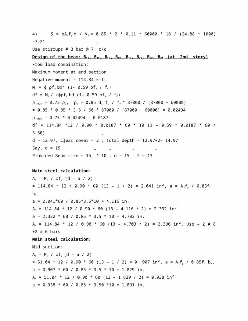
Y – Axis:
γ = 13 / 18 = 0.72, ex = Mx / P = 56.093 * 12 / 329.81= 2.04 in
ey = My / P = 1.78 * 12/329.81 = 0.06 in, ex / h = 2.04 / 18 = 0.113
Reinforcement Ratio: ρg =As / A g = 4.04 / 180 = 0.022
From Graph: Pn yo / f′c Ag = 0.91
Or Pn yo = 0.91 * 3.50 * 180 = 573.30 kips
Po / f′c Ag = 1.11 Or Po = 1.11 * 3.50 * 180 = 699.30 kips
X – Axis:
γ = 5 / 10 = 0.5, ex = Mx / P = 56.093 * 12/329.81= 2.04 in
ey = My / P = 1.78*12 / 329.81 = 0.06 in, ey / h = 0.06 / 10 = 0.006
Reinforcement ratio: ρg =As / A g = 4.04 / 180 = 0.022
From Graph: Pn xo / f′c Ag = 1.02
Or Pn xo = 1.02 * 3.50 * 180 = 642.60 kips
Po /f′c Ag = 1.11 Or Po = 1.11 * 3.50 * 180 = 699.30 kips
Here – 1 / Pn = 1 / Pnxo + 1 / Pnyo – 1 / Po
Or 1 / Pn = 1 / 642.60 + 1 / 573.30 – 1 / 699.30. Or Pn = 534.64 kips
Now, Pu = ф Pn. Or Pu = 0.65 * 534.64
Or Pu = 347.516 kips > 329.81 kips. So design is ok.
Design of the Column : C2, C3, C5, C 8, C9, C12, C14, C15
From load combination:
Pu = 532.65 Kips = 532.65 * 1.20 = 639.18 Kips
Now, Pu = α ф Ag (0 .85 f’c (1- ρg) + ρg fy)
Or 639.18 = 0.80 * 0.65 * Ag (0.85 * 3.5 (1- 0.025) + 0.025 * 60)
Or 639.18 = 2.288 Ag or Ag = 279.36 in2 or Ag= 12” *24”
Provided Column size = 12” * 24”, Ag = 288 in2
Main steel calculation:
Pu = α ф (0 .85 f′c (Ag - As) + Asfy)
Or 639.18 = 0.80 * 0.65 (0.85 * 3.5 (288 – As) + As * 60)
Or 639.18 = 445.54 – 1.547 As + 31.20 As
Or As = 6.53 in2 Use 4 # 8 bars + 8 # 6 bars As = 6.68 in2
Tie design:
Spacing: S = 16 D = 16 * 6 / 8 = 12” c/c, S = 48 d = 48 * 3 / 8 = 18” c/c
At least lateral dimension: S = 12” c/c, Use # 3 bar ties @ 12” c/c.
Y – Axis:

γ = 19 / 24 = 0.79, ex = Mx / P = 54.898 * 12 / 532.65 = 1.24 in
ey = My / P = 1.534 * 12 / 532.65 = 0.035 in, ex / h = 1.24 / 24 = 0.052
Reinforcement ratio: ρg = As / A g = 6.68 / 288 = 0.023
From Graph: Pn yo / f′c Ag = 0.98
Or Pn yo = 0.98 * 3.50 * 288 = 987.84 kips
Po / f′c Ag = 1.13 Or Po = 1.13 * 3.50 * 288 = 1139.04 kips
X – Axis: γ = 7 / 12 = 0.58, ex = Mx / P = 54.898 * 12 / 532.65 = 1.24 in
ey = My / P = 1.534 * 12 / 532.65 = 0.035 in, ey / h = 0.035 / 12 = 0.0029
Reinforcement Ratio: ρg = As / A g = 6.68 / 288 = 0.023
From Graph: Pn xo / f′c Ag = 1.13
Or Pn xo = 1.13 * 3.50 * 288 = 1139.04 kips
Po / f′c Ag = 1.0 Or Po = 1.05 * 3.50 * 288 = 1058.40 kips
Here – 1 / Pn = 1 / Pnxo + 1 / Pnyo – 1 / Po
Or 1 / Pn = 1 / 1058.40 + 1 / 987.84 – 1 / 1139.04 or Pn = 926.61 kips
Now, Pu = ф Pn or Pu = 0.65 * 926.61
Or Pu = 602.30 kips > 532.65 kips, so design is ok.
Design of the Column : C6, C7, C11, C13
From load combination:
Pu = 865.56 Kips = 865.56 * 1.20 = 1038.67 Kips
Now, Pu = α ф Ag (0 .85 f’c (1- ρg) + ρg fy)
Or 1038.67 = 0.80*0.65 * Ag (0.85 * 3.5 (1- 0.025) + 0.025 * 60)
Or 1038.67 = 2.288 Ag or Ag = 454 in2 or Ag = 18” * 26”
Provided Column size = 18” * 26”, Ag = 468 in2
Main steel calculation:
Pu = α ф (0 .85 f’c (Ag - As) + Asfy)
Or 1038.67 = 0.80 * 0.65 (0.85 * 3.5 (468 – As) + As * 60)
Or 1038.67 = 723.99– 1.547As + 31.20 As
Or As = 10.61 in2 use 4 # 10 bars + 6 # 9 bars As = 11.08 in2
Tie design:
Spacing: S = 16 D = 16 * 9/8 = 18” c/c, S = 48 d = 48 * 3/8 = 18” c/c
At least lateral dimension: S = 18” c/c, use # 3 bar ties @ 18” c/c.
Y – Axis:
γ = 21 / 26 = 0.80, ex = Mx / P = 0.971 * 12 / 865.56 = 0.013 in
ey = My / P = 61.64 * 12 / 865.56 = 0.85 in, ex / h = 0.013 / 26 = 0.0005

Reinforcement ratio: ρg = A s / A g = 11.08 / 468 = 0.024
From Graph: Pn yo / f′c Ag = 1.15
Or Pn yo = 1.15 * 3.50 * 468 = 1883.70 kips
Po / f′c Ag = 1.15 or Po = 1.15 * 3.50 * 468 = 1883.70 kips
X – Axis:
γ = 13 / 18 = 0.72, ex = Mx / P = 0.013 in, ey = My / P = 0.85 in
ey / h = 0.85 / 18 = 0.047
Reinforcement ratio: ρg = As / A g = 0.024
From Graph: Pn xo / f′c Ag = 1.00
Or Pn xo = 1.00 * 3.50 * 468 = 1638 kips
Po / f′cAg = 1.15 or Po = 1.15 * 3.50 * 468 = 1883.70 kips
Here – 1 / Pn = 1 / Pnxo + 1 / Pnyo – 1 / Po
Or 1/Pn = 1 / 1638 + 1 / 1883.70 – 1 / 1883.7 or Pn = 1638 kips
Now, Pu = ф Pn, or Pu = 0.65 * 163
The table below is showing size of different columns of the beam supported structure.
Table 3.16: Cross -section of the Column of the beam supported structure

Column design for flat plate structure
Design of the Column : C1, C4, C10, C16
From load combination:
Pu = 232.26 Kips = 232.26 * 2.0 = 464.52 Kips
Now, Pu = α ф Ag (0 .85 f’c (1- ρg) + ρg fy)
Or 464.52 = 0.80 * 0.65 * Ag (0.85 * 3.50 (1- 0.03) + 0.03 * 60)
Or 464.52 = 2.44 Ag Or Ag = 190.40 in2. Or Ag = 13.79” *13.79”
Provided Column size = 15” *15”, Ag = 225 in
Main steel calculation:
Pu = α ф (0 .85 fc (Ag - As) + Asfy)
Or 464.52 = 0.80 * 0.65 (0.85 * 3.50 (225 – As) + As * 60)
Or 464.52 = 348.70 – 1.547As + 31.20 As. Or As = 3.92 in2
Use 4 # 9 bars, As = 4.00 in2
Tie design:
Spacing: S = 16 D = 16 * 9/8 = 18” c/c, S = 48 d = 48 * 3 / 8 = 18” c/c
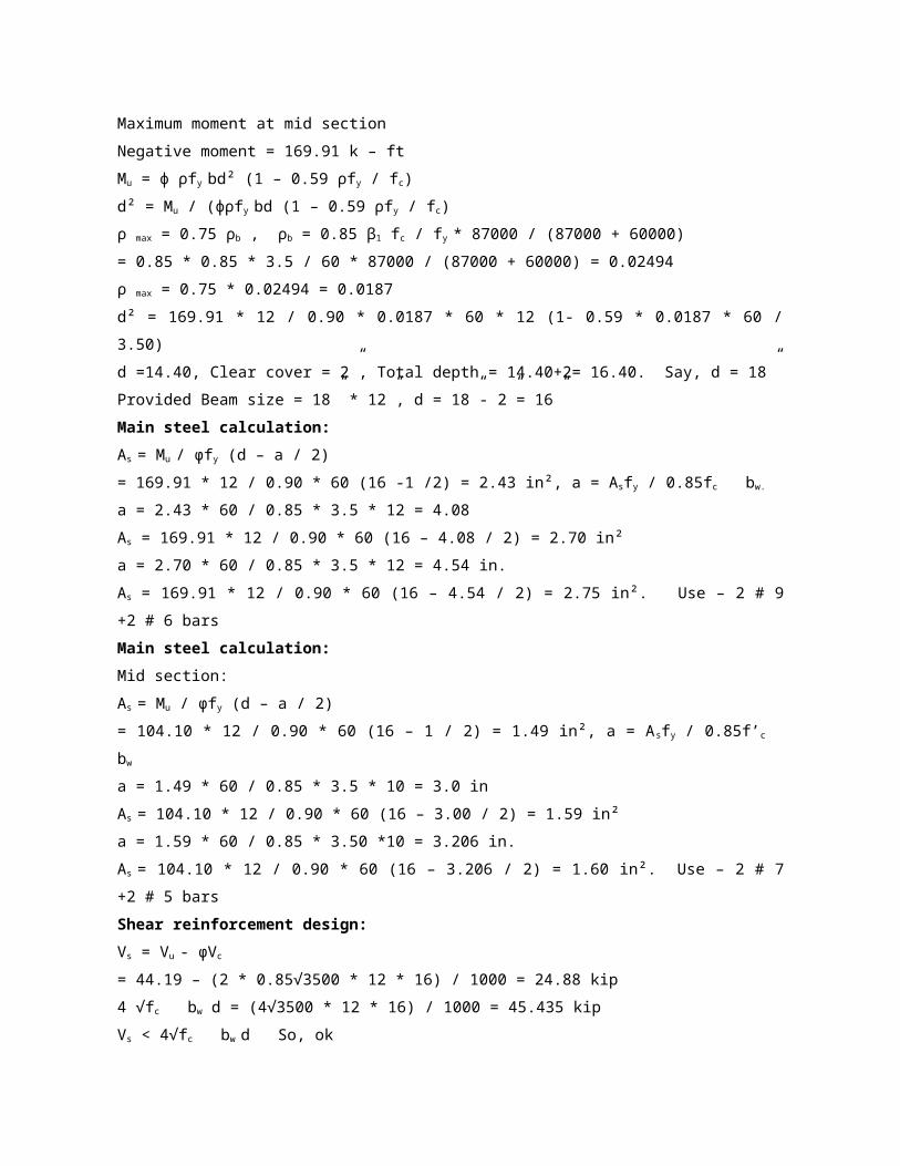
At least lateral dimension: S = 15” c/c, use # 3 bar ties @ 15” c/c.
Y – Axis:
γ = 10 / 15 = 0.67, ex = Mx / P = 94.34 * 12/232.26 = 4.87 in
ey = My / P = 3.293 * 12/232.26 = 0.17 in, ex / h = 4.87 / 15 = 0.32
Reinforcement ratio:
ρg = As / A g = 4.00 / 225 = 0.018
From Graph,
Pn yo / f′c Ag = 0.53
Or Pn yo = 0.53 * 3.50 * 225 = 417.37 kips, Po/ f′c Ag = 1.09
Or Po = 1.09 * 3.50 * 225 = 858.37 kips
X – Axis:
γ = 10 / 15 = 0.67, ex = Mx / P = 4.87 in, ey = My / P = 0.17 in
ey / h = 0.17 / 15 = 0.011
Reinforcement Ratio: ρg = As / A g = 0.018
From Graph:
Pn xo / f′c Ag = 1.06 Or Pn xo = 1.06 * 3.50 * 225 = 834.75 kips
Po / f′c Ag =1.09 Or Po = 1.09 * 3.50 * 225 = 858.37 kips
Here – 1/ Pn = 1 / Pnxo + 1 / Pnyo – 1 / Po
Or 1/Pn = 1 / 834.75+ 1 / 417.37– 1 / 858.37 Or Pn = 411.70 kips
Now, Pu = ф Pn. Or Pu = 0.65 * 411.70
Or Pu = 267.60 kips > 232.26 kips. So design is ok.
Design of the Column : C2, C3, C5, C8, C9, C12, C14, C15
From load combination:
Pu = 469.38 Kips = 469.38 * 1.20 = 563.25 Kips
Now, Pu = α ф Ag (0 .85 f’c (1- ρg) + ρg fy)
Or 563.25 = 0.80 * 0.65 * Ag (0.85 * 3.50 (1- 0.025) + 0.025 * 60)
Or 563.25 = 2.288 Ag Or Ag = 246.18 in2
Or Ag =12” *24”
Provided Column size =12” *24”
Ag = 288 in2
Main steel calculation:
Pu = α ф(0 .85 f’c (Ag - As) + Asfy)
Or 563.25 = 0.80 * 0.65 (0.85 * 3.50 (288 – As) + As * 60)
Or 563.25 = 445.54 – 1.547As + 31.20 As Or As = 3.97 in2

Use 4 # 8 bars + 2 # 6 bars, As = 4.04 in2
Tie design:
Spacing: S = 16 D = 16 * 6 / 8 = 12” c/c, S = 48 d = 48 * 3 / 8 = 18” c/c
At least lateral dimension, S = 12” c/c
Use # 3 bar ties @ 12” c/c.
Y – Axis:
γ = 19 / 24 = 0.79, ex = Mx / P = 94.668 * 12 / 469.38 = 2.42 in
ey = My / P = 2.533 * 12 / 469.38 = 0.065 in, ex / h = 2.42 / 24 = 0.10
Reinforcement ratio:
ρg = As / A g = 4.04 / 288 = 0.014
From Graph: Pn yo / f′c Ag = 0.86
Or Pn yo = 0.86 * 3.50 * 288 = 866.88 kips
Po / f′c Ag = 1.04 Or Po = 1.04 * 3.50 * 288 = 1048.32 kips
X – Axis:
γ = 7 / 12 = 0.58, ex = Mx / P = 2.42 in, ey = My / P = 0.065 in
ey / h = 0.85 / 18 = 0.047
Reinforcement ratio: ρg =As / A g = 0.014
From Graph: Pn xo / f′c Ag = 1.04
Or Pn xo = 1.04 * 3.50 * 288 = 1048.32 kips
Po / f′c Ag = 1.04 Or Po = 1.04 * 3.50 * 288 = 1048.32 kips
Here – 1 / Pn = 1 / Pnxo + 1 / Pnyo – 1 / Po
Or 1 / Pn = 1 / 1048.32+ 1 / 866.88– 1 / 1048.32
Or Pn = 869.56 kips
Now, Pu = ф Pn. Or Pu = 0.65 * 869.56
Or Pu = 565.21 kips > 469.38 kips. So design is ok.
Design of the Column : C6, C7, C11, C13
From load combination:
Pu = 1075.60 Kips = 1075.60 * 1.40 = 1505.84 Kips
Now, Pu = α ф Ag (0 .85 f’c (1- ρg) + ρg fy)
Or 1505.84 = 0.80 * 0.65 * Ag (0.85 * 3.50 (1- 0.03) + 0.03 * 60)
Or 1505.84 = 2.44 Ag Or Ag = 617.15 in Or Ag = 22” * 30”
Provided Column size = 22” * 30”
Ag = 660 in2

Main steel calculation:
Pu = α ф (0 .85 f’c (Ag - As) + Asfy)
Or 1505.84 = 0.80 * 0.65 (0.85 * 3.50 (660 – As) + As * 60)
Or 1505.84 =1021.02 – 1.547As + 31.20 As
Or As = 16.35 in2
Use 4 # 10 bars + 12 # 9 bars, As = 17.08 in2
Tie design:
Spacing: S = 16 D = 16 * 9 / 8 = 18” c/c, S = 48 d = 48 * 3 / 8 = 18” c/c
At least lateral dimension, S = 22” c/c, Use # 3 bar ties @ 18” c/c.
Y – Axis:
γ = 25 / 30 = 0.83, ex = Mx / P = 4.06 * 12 / 1075.60 = 0.045 in
ey = My / P = 135.407 * 12 / 1075.60 = 1.51 in
ex / h = 0.045 / 30 = 0.0015
Reinforcement ratio: ρg = As / A g = 17.08 / 660 = 0.026
From Graph: Pn yo / f′c Ag = 1.108
Or Pn yo = 1.108 * 3.50 * 660 = 2559.48 kips
Po / f′c Ag = 1.20 Or Po = 1.20 * 3.50 * 660 = 2772 kips
X – Axis:
γ = 17 / 22 = 0.77, ex = Mx / P = 0.045 in, ey = My / P = 1.51 in
ey / h = 1.51 / 22 = 0.0686
Reinforcement ratio: ρg = As / A g = 0.026
From Graph: Pn xo / f′c Ag = 1.09
Or Pn xo = 1.09 * 3.50 * 660 = 2517.90 kips
Po/ f′c Ag = 1.20
Or Po = 1.20 * 3.50 * 660 = 2772 kips
Here – 1 / Pn = 1 / Pnxo + 1 / Pnyo – 1 / Po
Or 1 / Pn = 1 / 2517.90 + 1 / 2559.48 – 1 / 2772
Or Pn = 2341.31kips
Now, Pu = ф Pn. Or Pu = 0.65 * 2341.31
Or Pu = 1521.85 kips > 1075.60 kips. So design is ok.
The table below is showing size of different columns of the flat plate structure
Table 3.17: Cross section of the column elements for flat plate structure.

COMPARATIVE STUDY:
General:
The buildings are analyzed for determine the best condition which can be constructed
economically. The behavior of each condition is observed carefully. Then suitable condition is
selected and suitable dimensions as well as steel area are also determined. The chapter gives a
comparative of the material, dimensions etc required for both the options I building and potion II
building. It is obvious that the amount of material required for option I building will be higher than
the option II building. But the option I building got beam free floor height. Due to this beam free
space, looks nice and the floor will be heavily reinforced and it will be durable.
Comparison Between the Two Types of Structure:
The comparison is made in terms of element dimension, volume of concrete and steel
requirement, their cost and economic view.
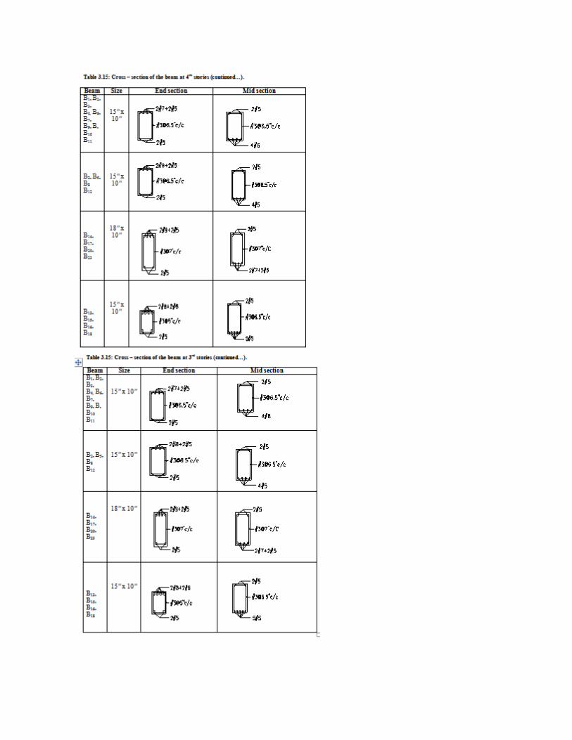
Dimension of different parts of beam supported structure and flat pate structure:
Table 4.1: Dimension of different portion of the flat plate structure and beam-supported
structure.
Element Option I building
(Beam supported structure)
Option II building
(Flat plate structure)
Column no There are 16 columns at each floor. So the total nos
of columns of this six storied building is 16.
There are 16 columns at each floor. So the total nos
of columns of this six storied building is 16.
Table 4.1: Dimension of different portion of the flat plate structure and beam-supported structure
(continued…).
Element Option I building
(Beam supported structure)
Option II building
(Flat plate structure)
Column size All the columns are:
1. C1,C4,C10,C16:
Size = 18” * 10”
2. C2,C3,C5,C8,C9,C12,C14,C15
Size = 24” * 12”
3. C6,C7,C11,C13:
Size = 26” * 18”
All the columns are:
1. C1,C4,C10,C16:
Size = 15” * 15”
2. C2,C3,C5,C8,C9,C12,C14,C15
Size = 24” * 12”
3. C6,C7,C11,C13:
Size = 30” * 22”
Column
height
All floor columns height are 10 ft All floor columns height are 10 ft
Beams Slab with beams Slab without beams
Slab
thickness
All floor slab thickness are 6″ All floor slab thickness are 7.5″
Required concrete volume for beam supported structure and flat plate structure:
Table 4.2: Comparative concrete volumes.
Element Option I building
(Beam supported structure)
Option II building
(Flat plate structure)
Column Column: C1, C4, C10, C16= 4 * 6 * 0’- 10” * 1’- 6” *
10’- 0” = 333.12 cft.Column: C2, C3, C5, C8, C9,
Column: C1, C4, C10, C16= 4 * 6 * 1’- 3” * 1’- 3” * 10’- 0” =
375.00 cftColumn: C2, C3, C5, C8, C9, C12, C14, C15= 8 * 6 *
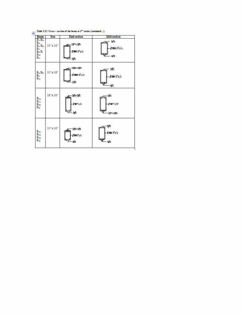
C12, C14, C15= 8 * 6 * 1’- 0” * 2’- 0 * 10’- 0” =
960.00 cft
Column: C6, C7, C11, C13
= 4 * 6 * 1’- 6” * 2’- 2” * 10’- 0” =
779.76 cft
Total R.C.C = 2072.88 cft.
1’- 0” * 2’- 0 * 10’- 0” = 960.00 cft
Column: C6, C7, C11, C13
= 4 * 6 * 1’- 10” * 2’- 6” * 10’- 0” = 1099.80 cft
Total R.C.C = 2434.80 cft
Table 4.2: Comparative concrete volumes (continued…)
Element Option I building
(Beam supported structure)
Option II building
(Flat plate structure)
Beams Beam: B1, B3, B4, B6, B7, B9, B10, B11= 1 * 10” * 10” * 13’ – 7” * 8=
75.46 cftBeam: B2, B5, B8, B12
= 1 * 15” * 10” * 18’ – 0” * 4
= 75.00 cft
Beam: B14, B17, B20, B23
= (1 * 18” * 10” * 17’-10” * 2) + (1 * 18”10” * 18’-5” * 2)
= 90.83 cft
Beam: B13, B15, B16, B18, B19, B21, B22, B24
= 1 * 12” * 10” * 13’-5” * 8
= 89.46 cft
Total R.C.C = 75.46 + 75.00 + 90.83 + 89.46 = 330.75
cft
None
Table 4.2: Comparative concrete volumes (continued…).
Element Option I building
(Beam supported structure)
Option II building
(Flat plate structure)
Beams (5th + 6th) Floor R.C.C= 2 * 330.75 = 661.50 cftR.C.C Beam at 4 th Story: Beam:
B1, B3, B4, B6, B7, B9, B10, B11
= 1 * 15” * 10” * 13’ – 7” * 8
= 113.17 cft
Beam: B2, B5, B8, B12
=1 * 15” * 10” * 18’ – 0” * 4
None

= 75.00 cft
Beam: B14, B17, B20, B23
= (1 * 18” * 10” * 17’- 10” * 2) + (1 * 18” *10” * 18’- 5” * 2)
= 90.83 cft
Beam: B13, B15, B16, B18, B19, B21, B22, B24
= 1 * 15” * 10” * 13’-5” * 8
= 113.17 cft
Total R.C.C = 113.17 + 75.00 + 90.83 + 113.17 = 392.17 cft
(3rd + 4TH) Floor R.C.C = 2 * 392.17 = 784.34 cft
R.C.C Beam at 2 nd Story:
Beam: B1, B3, B4, B6, B7, B9, B10, B11
= 1 * 15” * 12” * 13’- 7” * 8
= 135.80 cft
Beam: B2, B5, B8, B12
= 1 * 15” * 10” * 18’- 0” * 4
= 75.00 cft
Beam: B14, B17, B20, B23
Table 4.2: Comparative concrete volumes (continued..).
Element Option I building
(Beam supported structure)
Option II building
(Flat plate structure)
Beam = (1 * 18” * 12”*17’- 10” * 2) + (1 * 18” * 12” * 18’-5” *
2)= 108.99 cftBeam: B13, B15, B16, B18, B19, B21, B22,
B24= 1 * 15” * 10” * 13’-5” * 8
= 113.17 cft
Total R.C.C = 135.80 + 75.00 + 108.99 +
113.17 = 432.96 cft
(1st + 2nd) Floor R.C.C = 2 * 432.96 =
865.92 cft
Total R.C.C = 135.80 + 75.00 + 108.99 +
113.17 = 432.96 cft
(1st + 2nd) Floor R.C.C = 2 * 432.96 =
865.92 cft
Total R.C.C of beam: 661.50 + 784.34 +
None

865.92 = 2311.76 cft.
Slab Concrete in slab for one story:1 * 50.83 * 50.83 * (6 /
12)= 1292 cftConcrete in slab for six stories:
1 * 1292*6 = 7752 cft
Concrete in slab for one story:1 * 51.33 * 51.33 * 7.5
/ 12= 1647 cft.Concrete in slab for six stories:
1 * 1647 * 6 = 9882 cft
Required steel volume for beam supported structure and flat plate structure.
Table 4.3: Comparative steel volumes.
Element Option I building
(Beam supported structure)
Option II building
(Flat plate structure)
Column Column: C1, C4, C10, C164 # 9 bars = 4 * 4 * 65’- 6”=
1048 rft# 3 bars @ 15” c/c
= 49 * 4 * 4’- 4”= 849.26 rft
Column: C2, C3, C5, C8, C9, C12, C14, C15
4 # 8 bars = 4 * 8 * 65’- 0”
= 2080 rft
2 # 6 bars = 2 * 8 * 64’ – 0”
= 1024 rft
# 3 bars @ 12” c/c = 61 * 8 * (5’- 4” + 1’-
1”) = 3131 rft
Column: C6, C7, C11, C13
4 # 10 Bars = 4 * 4 * 66’- 4”
= 1061.28 rft
12 # 9 bars = 12 * 4 * 65’- 6”
= 3144 rft
# 3 bars @ 18” c/c = 41 * 4 * (8’- 0”+ 5’-
10”+ 4’- 5”) = 2992.84 rft
# 8 Bars = 2080 rft = 2444 kg
# 6 bars = 4608 rft = 3464 kg
# 9 Bars = 4192 rft = 6180.64 kg
Column: C1, C4, C10, C164 # 8Bars = 4 * 4 * 65’- 0”=
1040 rft2 # 6 Bars = 2 * 4 * 64’- 0”
= 512 rft
# 3 bars @ 10” c/c
= 4 * (73 * 4’- 0” + 73 * 0’- 11”)
= 1435.48 rft
Column: C2, C3, C5, C8, C9, C12, C14, c15
4 # 8 Bars = 4 * 8 * 65’- 0”
= 2080 rft
8 # 6 Bars = 8 * 8 * 64’- 0”
= 512 rft
= 4096 rft
# 3 Bars @ 12” c/c
= 61 * 8 * (5’- 4”+3’- 3”+1’- 11”) = 5123.67
rft
Table 4.3: Comparative steel volumes (continued..).

Element Option I building
(Beam supported structure)
Option II building
(Flat plate structure)
Column # 10 Bars = 1061.28 Rft= 2043 kg# 3 Bars = 6973.10 Rft =
1309.58 kgTotal M.S Rod = 11977.00 kgTotal M.S Rod
=11977.00 kg
= 11.98 ton
Column: C6, C7, C11, C134 # 10 Bars= 4 * 4 * 66’-
4” = 1061.28 rft6 # 9 bars
= 6 * 4 * 65’- 6”= 1572 rft
# 3 bars @ 18” c/c
= 41* 4 * (6’- 8”+2’- 3”+ 4’- 2”) =
2145.55 rft
# 8 bars = 3120 rft = 3666 kg
# 6 bars = 4608 rft = 3464 kg
# 9 Bars = 1572 rft = 2318 kg
# 10 bars = 1061.28 rft = 2043 kg
# 3 bars = 8704.22 rft = 1635 kg
Total M.S Rod = 13126.00 kg
Total R.C.C = 2072.88 cft
Total M.S Rod =13126 kg
=13.126 ton
Beam M.S Rod of beam at 6 th Story: Beam: B1, B2, B3, B4, B5, B6, B7,
B8, B9, B10, B11, B12Top Bars: 2 # 5
=1 * 51.17’ * 2 * 2 = 204.68 ft * 0.481 = 98.45 kg
Bottom Bars: 3# 5
= 1 * 51.17’ * 3 * 4 = 614.04 ft * 0.481 = 295.35
kg
Mid = 1 * 10’ * 2 * 4 = 80.00 ft * 0.481 = 38.48 kg
None
Table 4.3: Comparative steel volumes (continued…).
Element Option I building
(Beam supported structure)
Option II building
(Flat plate structure)
Beam Extra top End: 2 # 7= 1 * 5.92’ * 2 * 8 = 94.72ft *
0.911 = 86.29 kgExtra top mid: 2 # 7 & 1 # 5= 1 *
None
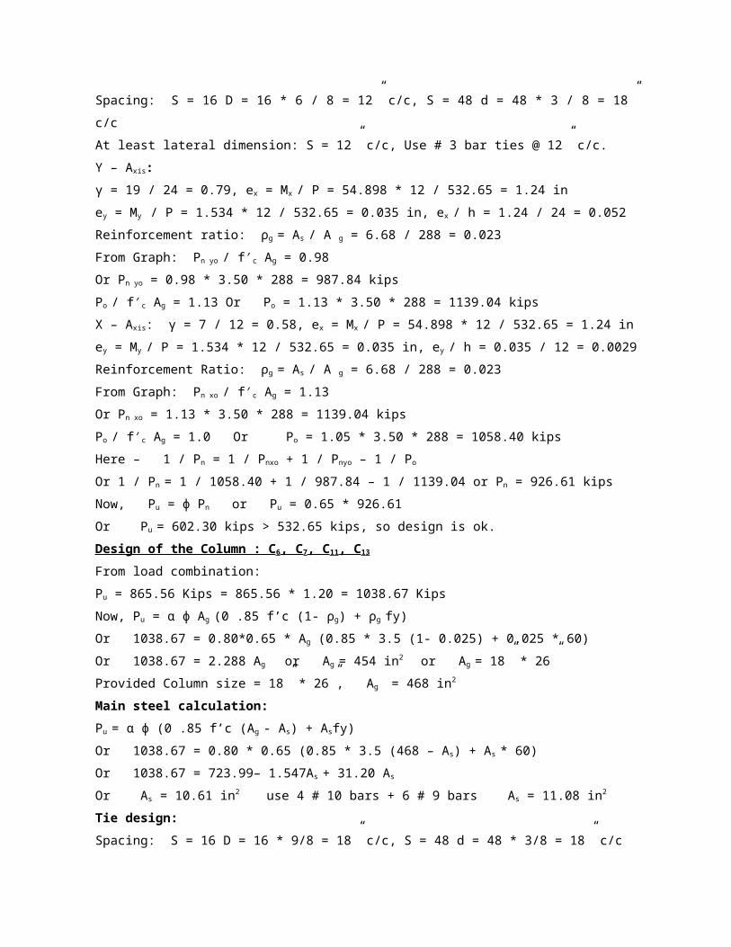
9.5’ * 2 * 8 = 152.00 ft * 0.911 = 138.47 kg
= 1* 9.5’ * 8 = 76.00 ft * 0.481
= 36.56 kg
Stirrups #3Bars@ 6.50” C/C
= 85 * 3.75 * 4 = 1275 ft * 0.188 =
239.70 kg
Total Rod = 933.30 kg
Beam: B13, B14, B15, B16, B17, B18
Top Bars: 2#5
= 1 * 51.17’ * 2 * 2 = 204.68 ft * 0.481 =
98.45 kg
Bottom Bars: 2 # 6 &2 # 5
= 1 * 51.17’ * 2 * 2 = 204.68 ft * 0.752 =
153.92 kg
= 1* 51.17’ * 2 * 2 = 204.68 ft * 0.481 =
98.45 kg
Extra top End: 2 # 7
= 5.92’ * 2 * 2 * 2 = 47.36 ft * 0.911 =
43.14 kg
Extra top mid: 2 # 8
= 1 * 9.5’ * 2 * 2 * 2 = 760.00 ft * 1.176 =
89.34 kg
Table 4.3: Comparative steel volumes (continued..).
Element Option I building
(Beam supported structure)
Option II building
(Flat plate structure)
Beam Total = 483.30 * 2 = 966.60 kgStirrups # 3 bars @
6.50” C / C= 85 * 3.75 * 4 = 1275 ft * 0.188 =
239.70 kgTotal = 1206.30 kg
Total Rod at 6th Floor = 933.30 +
1206.30 = 2139.60 kg
M.S Rod of Beam at 1 st floor:
Beam: B1, B2, B3, B4, B5, B6, B7, B8, B9,
None

B10, B11
Top Bars: 2 # 5
= 2 * 51.17’ * 4 = 409.36 ft * 0.481 =
196.90 kg
Bottom bars: 3 # 5
= 1 * 51.17’ * 3 * 4 = 614.04 ft * 0.481 =
295.35 kg
Extra top end: 4 # 6
= 1 * 5.92’ * 4 * 8 = 189.44 ft * 0.75 =
142.46 kg
Extra top mid: 2 # 9
= 1 * 9.5’ * 2 * 8 = 152.00 ft * 1.536 =
233.47 kg
Stirrups # 3 bars @ 6.50” C/C
= 85 * 3.75 * 4 = 1275 ft * 0.188 =
239.70 kg
Beam: B13, B14, B15, B16, B17, B18, B19, B20,
B21, B22, B23, B24
Top bars: 2 # 5
Table 4.3: Comparative steel volumes (continued..).
Element Option I building
(Beam supported structure)
Option II building
(Flat plate structure)
Beam = 2 * 51.17’ * 4 = 409.36 ft * 0.481 = 196.90
kgBottom bars: 2 # 7 & 2 # 5= 2 * 20’ * 8 = 320.00
ft * 0.911 = 291.52 kg= 2 * 51.17’ * 8 = 818.72 ft *
0.481 = 393.80 kg
Extra top end: 2 # 8 & 2 # 6
= 2 * 5.92’ * 2 * 2 * 2 = 94.72 ft * 1.176 =
111.39 kg
= 2 * 5.92’ * 8 = 94.72 = 0.752
= 71.22 kg
Extra top mid: 2 # 9, 2 # 6 & 1 # 5
= 2 * 9.5’ * 2 * 2 * 2 = 152.00 ft * 1.536 =
None
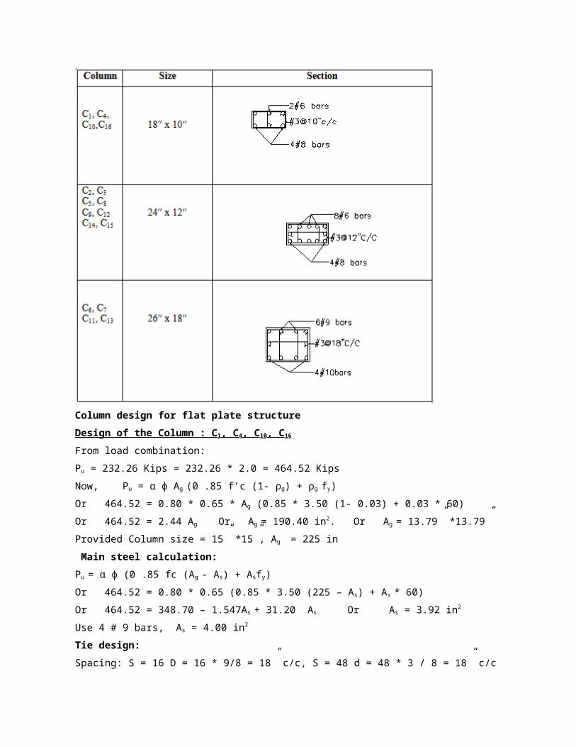
233.47 kg
= 2 * 9.5’ * 8 = 152.00 ft * 0.752 =
114.30 kg
= 1*15’* 8= 120.00 ft *0.481
= 57.72
Stirrups # 3 bars @ 6.50” C/C
= 85 * 3.75 * 8 = 2550.00 ft * 0.188 =
479.40 kg
Total = 3077.43 kg
6th Story = 2139.60 kg
1st Story = 3077.43 kg
Total = 5217.03 kg
Table 4.3: Comparative steel volumes (continued..).
Element Option I building
(Beam supported structure)
Option II building
(Flat plate structure)
Beam 5th to 2nd story = 5217.03/2= 2608.51 kgTotal Rod =
2139.60+2608.51 * 4+3077.43 = 15651.07 kg
None
Slab 15 ft*15 ft slab:4.375 * (6+9+5) = 87.5 ft15.42 *
(6+9+5) = 308 ft5.14 * (6+10+5) = 108 ft
4.375 * (6+9+5) = 87.5 ft
15.42 * (6+9+5) = 308 ft
5.14 * (6+11+5) = 113 ft
= 1012 ft
15 ft*20 ft slab:
4.16 * (8+15) = 96 ft
5.14 * (8+15) = 118 ft
15.42 * (8+15) = 355 ft
5 * (6+13+5) * 2 = 240 ft
20 * (6+9+5) = 400 ft
= 1209 ft
20 ft*20 ft slab:
6.81 * (12+12) = 327 ft
1S: 6 * 15.7’ = 94 ft (+ve)5 * (4.1’+ 16/12)= 27.2 ft
(Ex. – ve)11 * (4.1’+ 8/12)
= 52.43 ft (In. – ve)
= 94 + 27.2 + 52.43 = 173.63 ft.
1L: 7 * 15.7’ = 109.9 ft (+ve)
6 * (4.1’+ 16 / 12)
= 32.6 ft (Ex. – ve)
12 * (4.1’+ 8 / 12)
= 57.2 ft (In. – ve)
= 109.9 + 32.6 + 57.2
= 199.7 ft.
2S: 7 * 15.7’ = 109.9 ft (+ve)
7 * (3’+ 16/12)
= 30.33 ft (Ex. – ve)
7 * (3’+ 8/12)

20 * (12+12) = 480 ft
6.81 * (12+13) * 2 = 341 ft
20*(12+12) = 480 ft
= 1628 ft
= 25.6 ft (In. – ve)
= 109.9 + 30.33 + 25.6
= 165.83 ft.
Table 4.3: Comparative steel volumes (continued..).
Element Option I building
(Beam supported structure)
Option II building
(Flat plate structure)
Slab Total steel in slab = 1012 + 1209 + 1628 = 3849 ft
= 3849 * (0.11 / 144)= 2.94 cft= 1440.6 lb= 653 kg.
= 0.653 tonTotal steel in slab for six stories: 1 *
0.653 * 6 = 3.92 ton
2L: 165.83 ft.For panel 1: 173.63 * 2 + 199.70 * 2 +
165.83 * 2 = 1078.32 ft.3: 9 * 20’ = 180 ft (+ve)11 *
2 * (5.6’ + 8/12)
= 137.87 ft (-ve)
11 * 2 * (3.74’+ 8/12)
= 96.82
= 180 + 137.87 + 96.82
= 414.69 ft.
4: 7 * 20’ = 140 ft (+ve)
= 206.73 ft.
5: 9 * 15.7 = 141.3 ft (+ve)
7 * (5.6’+ 16/12)
= 48.53 ft (Ex. – ve)
8 * (5.6’+ 8/12)
= 50.13 ft (In. – ve)
7 * (3.74’+ 8/12)
= 30.85 ft (In. – ve)
=141.3+48.53 +50.13 + 30.85
= 270.81 ft.
6: 11 * 15.7 = 172.7 ft (+ve)
11 * (4.1’+ 16/12)
= 59.77 ft (Ex. – ve)
= 172.7 + 59.77 = 284.9 ft.
For Panel 2: 414.69 * 2 + 206.73 +
270.81 * 2 + 284.9 = 1862.63 ft.

Table 4.3: Comparative steel volumes (continued..).
Element Option I building
(Beam supported structure)
Option II building
(Flat plate structure)
Slab 7S: 11 * 20 = 220 ft (+ve)14 * 2 * (5.6’+8/12)= 175.5
ft (-ve)13 * 2 * (3.74’+ 8/12)
= 114.57 ft (-ve)
= 175.5 + 114.57 = 510.1 ft.
7L: 12 * 20 = 240 ft (+ve)
14 * 2 * (5.6’+ 8/12)
= 175.5 ft (-ve)
13 * 2 * (3.74’+ 8/12)
= 114.57 ft (-ve)
= 240 +175.5 +114.57= 530.1 ft.
8S: 9 * 20 = 180 ft (+ve)
9 * 2 * (4.1’+ 8 / 12)
= 85.8 ft (-ve)
= 180 + 85.80 = 265.8 ft.
8L: 265.8 ft.
For panel 3: 510.10 * 2 + 265.8 +
530.10 * 2 + 265.8 = 2612 ft
Total steel: 1078.32 * 4 + 1862.63 * 4 +
2612 = 14376 ft
= 19.67 cft = 4.38 ton.
Total steel in slab for six stories
= 1 * 4.38 * 6 = 26.28 ton
Summary of the Comparative Study:
This cost analyses, shown in Table 4.4, are completed according to “schedule of rate for civil
works”, 12thedition, PWD and as per considerations made in Chapter IV, Art 4.3.
Table 4.4: Cost analysis for volume of concrete of beam supported structure.
Sl. no. Short Unit Total Rate Amount (Tk.)
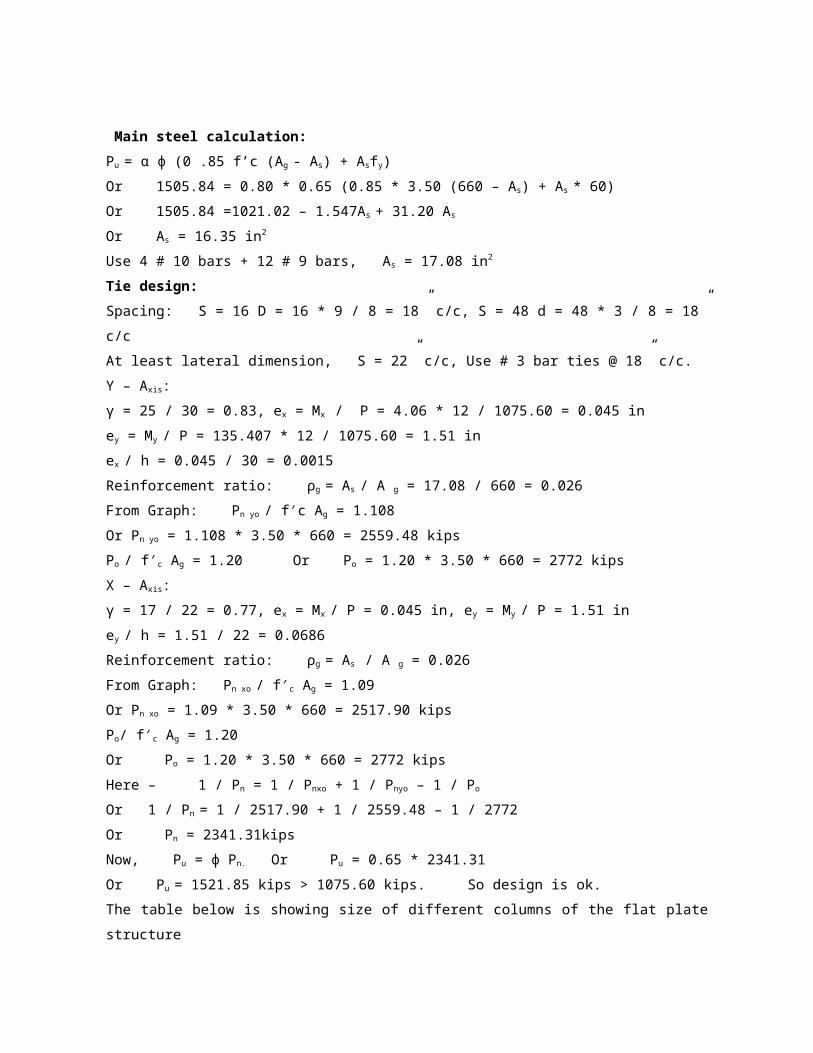
description (Tk.)
Option I:
Beam supported structure
i. Ground
Floor
201 406576.77
cft 2022.77
ii. 1st Floor cft 2022.77 205 414667.85
iii. 2nd Floor cft 2022.77 209 422758.93
iv. 3rd Floor cft 2022.77 213 430850.01
v. 4th Floor cft 2022.77 217 438941.09
vi) 5th Floor cft 2022.77 221 447032.17
Total costing for concrete works = Tk.25,60,826.82
Table 4.5: Cost analysis for volume of concrete of flat plate structure.
Sl. no. Short
description
Unit Total Rate
(Tk.)
Amount (Tk.)
Option II: Flat plate
structure
i. Ground Floor cft 2052.80 201 412612.80
ii. 1st Floor cft 2052.80 205 420824.00
iii. 2nd Floor cft 2052.80 209 429035.20
iv. 3rd Floor cft 2052.80 213 437246.40
v. 4th Floor cft 2052.80 217 445457.60
vi) 5th Floor cft 2052.80 221 453668.80
Total costing for concrete works = Tk.25,98,844.80
The cost analyses of the both structures are summarized in table below.
Table 4.6: Cost analysis for volume of 60 grade deformed bar (steel) of beam supported
structure.
Sl. no. Short Unit Total Rate Amount (Tk.)

description (Tk.)
Option I: Beam supported
structure
i. Ground Floor Kg 5450 86.9
9
474095.50
ii. 1st Floor Kg 5450 87.2
3
475403.50
iii. 2nd Floor Kg 5450 87.4
7
476711.50
iv. 3rd Floor Kg 5450 87.7
1
478019.50
v. 4th Floor Kg 5450 87.9
5
479327.50
vi. 5th Floor Kg 5450 88.1
9
480635.50
Total costing for concrete works = Tk.28,64,193.00
Table 4.7: Cost analysis for volume of 60 grade deformed bar (steel) for flat plate
structure.
Sl. no. Short
description
Unit Total Rate
(Tk.)
Amount (Tk.)
Option II: Flat plate
structure
i. Ground Floor Kg 6050 86.9
9
526289.50
ii. 1st Floor Kg 6050 87.2
3
527741.50
iii. 2nd Floor Kg 6050 87.4
7
529193.50
iv. 3rd Floor Kg 6050 87.7
1
530645.50
v. 4th Floor Kg 6050 87.9
5
532097.50

vi. 5th Floor Kg 6050 88.1
9
533549.50
Total costing for concrete works = Tk.31,79,517.00
Grand Total (I+II) = Tk.11,203,381.62
The table below is showing total concrete requirement, steel requirement and cost difference for
flat plate structure and beam-supported structure.
Table 4.8: Summary of cost analyses for both structures
Type of
structure
Total
volume of
concrete
works
(cft)
Total
volume of
steel
works
(kg)
Total costing
of concrete
works
(Tk)
Total costing
of steel works
(Tk)
Remarks
Beam
supported
structure
12136.64 32700.00 25,60,826.82 28,64,193.00 About 6.5
% more
cost
required for
flat plate
structure
Flat plate
structure
12316.80 36300.00 25,98,844.80 31,79,517.00
CONCLUSION AND RECOMMENDATION
Recommendations for Further Study:
For further study in this field, the following recommendations are put forward:
i) The study needed use of conventional finite element software and manual calculation for both
analysis and design of whole structures to give a comprehensive conclusion.
ii) Instead of one residential square building of about 3.5 katahs it requires other geometrically
shaped and larger areas residential building for accurate comparison.
Conclusions:
From the comparative study of beam supported structure and flat plate structure, we gathered
knowledge that:
a) From the Finite Element Analysis result it can be said that the internal forces in the flat plate
structure is higher than that of beam supported structure.

b) The construction of flat plate structure requires more construction material which results in
more cost. Such as, concrete requirement increased in flat plate structure about 1.5% and steel
requirement about 11% and finally increased cost of 6.5% than beam supported structure.
c) In case of flat plate structure interior space of building looks nice, due to absence of beams
offset. Flat plate slab is thicker and more heavily reinforced than slabs with beams and girders.
d) It is apparent from the cost comparison that the difference between two estimates is very
insignificant and moreover this difference is for only frame of the building. The cost per unit area
for finishing items will remain same for all cases. In compare to the enormous benefit that can be
gained for aesthetic view and also for light provision, the cost increase in this case is very
insignificant.
References:
1. ACI Code, 1995, USA
2. ETABS -Version 8.2.7
3. BNBC (1993), “Bangladesh National Building Code” 1st edition, city Art Press,
Bangladesh.
4. “Design of concrete structure”- 13th edition by Arthur H. Nilson, David Darwin, Charles W.
Dolan.
1. “Schedule of Rate for Civil works”, 11th edition, Public works department,
Government of the Peoples Republic of Bangladesh, 21st November. 2008.
Top Related