


Languages
Pages
Legal


EAV6
4367
-01
Altivar Process ATV600 Application Note Multi-Masters with Optimized Level Control
06/2018
2 EAV64367-01 06/2018
The information provided in this documentation contains general descriptions and/or technical characteristics of the performance of the products contained herein. This documentation is not intended as a substitute for and is not to be used for determining suitability or reliability of these products for specific user applications. It is the duty of any such user or integrator to perform the appropriate and complete risk analysis, evaluation and testing of the products with respect to the relevant specific application or use thereof. Neither Schneider Electric nor any of its affiliates or subsidiaries shall be responsible or liable for misuse of the information contained herein. If you have any suggestions for improvements or amendments or have found errors in this publication, please notify us.
You agree not to reproduce, other than for your own personal, noncommercial use, all or part of this document on any medium whatsoever without permission of Schneider Electric, given in writing. You also agree not to establish any hypertext links to this document or its content. Schneider Electric does not grant any right or license for the personal and noncommercial use of the document or its content, except for a non-exclusive license to consult it on an "as is" basis, at your own risk. All other rights are reserved.
All pertinent state, regional, and local safety regulations must be observed when installing and using this product. For reasons of safety and to help ensure compliance with documented system data, only the manufacturer should perform repairs to components.
When devices are used for applications with technical safety requirements, the relevant instructions must be followed.
Failure to use Schneider Electric software or approved software with our hardware products may result in injury, harm, or improper operating results.
Failure to observe this information can result in injury or equipment damage.
© 2017 Schneider Electric. All rights reserved.
EAV64367 01 3
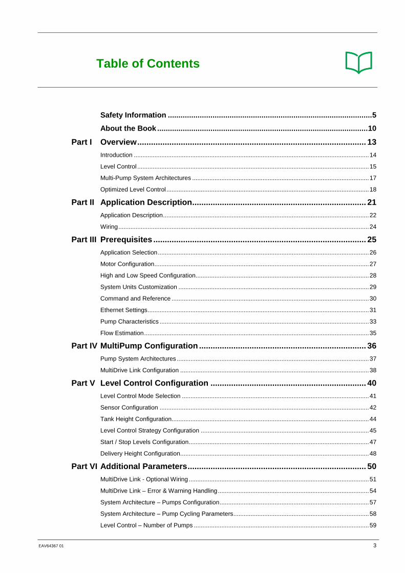
Table of Contents
Safety Information ................................................................................................ 5
About the Book ................................................................................................... 10
Part I Overview .................................................................................................... 13
Introduction ......................................................................................................................................... 14 Level Control ....................................................................................................................................... 15 Multi-Pump System Architectures ....................................................................................................... 17 Optimized Level Control ...................................................................................................................... 18
Part II Application Description ............................................................................ 21
Application Description ........................................................................................................................ 22 Wiring .................................................................................................................................................. 24
Part III Prerequisites ............................................................................................. 25
Application Selection ........................................................................................................................... 26 Motor Configuration ............................................................................................................................. 27 High and Low Speed Configuration ..................................................................................................... 28 System Units Customization ............................................................................................................... 29 Command and Reference ................................................................................................................... 30 Ethernet Settings ................................................................................................................................. 31 Pump Characteristics .......................................................................................................................... 33 Flow Estimation ................................................................................................................................... 35
Part IV MultiPump Configuration ......................................................................... 36
Pump System Architectures ................................................................................................................ 37 MultiDrive Link Configuration .............................................................................................................. 38
Part V Level Control Configuration .................................................................... 40
Level Control Mode Selection ............................................................................................................. 41 Sensor Configuration .......................................................................................................................... 42 Tank Height Configuration ................................................................................................................... 44 Level Control Strategy Configuration .................................................................................................. 45 Start / Stop Levels Configuration ......................................................................................................... 47 Delivery Height Configuration .............................................................................................................. 48
Part VI Additional Parameters .............................................................................. 50
MultiDrive Link - Optional Wiring ......................................................................................................... 51 MultiDrive Link – Error & Warning Handling ........................................................................................ 54 System Architecture – Pumps Configuration ....................................................................................... 57 System Architecture – Pump Cycling Parameters ............................................................................... 58 Level Control – Number of Pumps ...................................................................................................... 59

4 EAV64367-01 06/2018
Level Control – Random Factor .......................................................................................................... 60 Level Control – Error & Warning Handling .......................................................................................... 61
Part VII Parameters Table ...................................................................................... 62
Parameter Table ................................................................................................................................. 63
EAV64367 01 5
Safety Information
Important Information
NOTICE
Read these instructions carefully, and look at the equipment to become familiar with the device before trying to install, operate, or maintain it. The following special messages may appear throughout this documentation or on the equipment to inform of potential hazards or to call attention to information that clarifies or simplifies a procedure.
The addition of this symbol to a “Danger” or “Warning” safety label indicates that an electrical hazard exists, which will result in personal injury if the instructions are not followed.
This is the safety alert symbol. It is used to alert you to potential personal injury hazards. Obey all safety messages that follow this symbol to avoid possible injury or death.
DANGER DANGER indicates an hazardous situation which, if not avoided, will results in death or serious injury.
WARNING
WARNING indicates a hazardous situation which, if not avoided, could result in death or serious injury.
CAUTION CAUTION indicates a hazardous situation which, if not avoided, could result in minor or moderate injury.
NOTICE
NOTICE is used to address practices not related to physical injury.
PLEASE NOTE
Electrical equipment should be installed, operated, serviced, and maintained only by qualified personnel. No responsibility is assumed by Schneider Electric for any consequences arising out of the use of this material.
A qualified person is one who has skills and knowledge related to the construction and operation of electrical equipment and its installation, and has received safety training to recognize and avoid the hazards involved.

6 EAV64367-01 06/2018
Qualification Of Personnel
Only appropriately trained persons who are familiar with and understand the contents of this manual and all other pertinent product documentation are authorized to work on and with this product. In addition, these persons must have received safety training to recognize and avoid hazards involved. These persons must have sufficient technical training, knowledge and experience and be able to foresee and detect potential hazards that may be caused by using the product, by changing the settings and by the mechanical, electrical and electronic equipment of the entire system in which the product is used. All persons working on and with the product must be fully familiar with all applicable standards, directives, and accident prevention regulations when performing such work.
Intended Use
This product is a drive for three-phase synchronous, asynchronous motors and intended for industrial use according to this manual. The product may only be used in compliance with all applicable safety standard and local regulations and directives, the specified requirements and the technical data. The product must be installed outside the hazardous ATEX zone. Prior to using the product, you must perform a risk assessment in view of the planned application. Based on the results, the appropriate safety measures must be implemented. Since the product is used as a component in an entire system, you must ensure the safety of persons by means of the design of this entire system (for example, machine design). Any use other than the use explicitly permitted is prohibited and can result in hazards. Electrical equipment should be installed, operated, serviced, and maintained only by qualified personnel.
EAV64367 01 7
Product Related Information
Read and understand these instructions before performing any procedure with this drive.
DANGER HAZARD OF ELECTRIC SHOCK, EXPLOSION OR ARC FLASH
• Only appropriately trained persons who are familiar with and understand the contents of this manual and all other pertinent product documentation and who have received safety training to recognize and avoid hazards involved are authorized to work on and with this drive system. Installation, adjustment, repair and maintenance must be performed by qualified personnel. • The system integrator is responsible for compliance with all local and national electrical code requirements as well as all other applicable regulations with respect to grounding of all equipment. • Many components of the product, including the printed circuit boards, operate with mains voltage. • Only use properly rated, electrically insulated tools and measuring equipment. • Do not touch unshielded components or terminals with voltage present. • Motors can generate voltage when the shaft is rotated. Prior to performing any type of work on the drive system, block the motor shaft to prevent rotation. • AC voltage can couple voltage to unused conductors in the motor cable. Insulate both ends of unused conductors of the motor cable. • Do not short across the DC bus terminals or the DC bus capacitors or the braking resistor terminals. • Before performing work on the drive system:
o Disconnect all power, including external control power that may be present. Take into account that the circuit breaker or main switch does not de-energize all circuits. o Place a Do Not Turn On label on all power switches related to the drive system. o Lock all power switches in the open position. o Wait 15 minutes to allow the DC bus capacitors to discharge. o Follow the instructions given in the chapter "Verifying the Absence of Voltage" in the installation manual of the product.
• Before applying voltage to the drive system: o Verify that the work has been completed and that the entire installation cannot cause hazards. o If the mains input terminals and the motor output terminals have been grounded and short-circuited, remove the ground and the short circuits on the mains input terminals and the motor output terminals. o Verify proper grounding of all equipment. o Verify that all protective equipment such as covers, doors, grids is installed and/or closed
Failure to follow these instructions will result in death or serious injury.
Drive systems may perform unexpected movements because of incorrect wiring, incorrect settings, incorrect data or other errors.
WARNING UNANTICIPATED EQUIPMENT OPERATION
• Carefully install the wiring in accordance with the EMC requirements. • Do not operate the product with unknown or unsuitable settings or data. • Perform a comprehensive commissioning test.
Failure to follow these instructions can result in death, serious injury, or equipment damage.
Damaged products or accessories may cause electric shock or unanticipated equipment operation.
DANGER ELECTRIC SHOCK OR UNANTICIPATED EQUIPMENT OPERATION
Do not use damaged products or accessories.
Failure to follow these instructions will result in death or serious injury.
Contact your local Schneider Electric sales office if you detect any damage whatsoever.
8 EAV64367-01 06/2018
WARNING LOSS OF CONTROL
• The designer of any control scheme must consider the potential failure modes of control paths and, for critical control functions, provide a means to achieve a safe state during and after a path failure. Examples of critical control functions are emergency stop, overtravel stop, power outage and restart. • Separate or redundant control paths must be provided for critical control functions. • System control paths may include communication links. Consideration must be given to the implications of unanticipated transmission delays or failures of the link. • Observe all accident prevention regulations and local safety guidelines (1). • Each implementation of the product must be individually and thoroughly tested for proper operation before being placed into service.
Failure to follow these instructions can result in death, serious injury, or equipment damage. (1) For USA: Additional information, refer to NEMA ICS 1.1 (latest edition), Safety Guidelines for the Application, Installation, and Maintenance of Solid State Control and to NEMA ICS 7.1 (latest edition), Safety Standards for Construction and Guide for Selection, Installation and Operation of Adjustable-Speed Drive Systems.
NOTICE DESTRUCTION DUE TO INCORRECT MAINS VOLTAGE
Before switching on and configuring the product, verify that it is approved for the mains voltage
Failure to follow these instructions can result in equipment damage.
The temperature of the products described in this manual may exceed 80 °C (176 °F) during operation.
WARNING HOT SURFACES
• Ensure that any contact with hot surfaces is avoided. • Do not allow flammable or heat-sensitive parts in the immediate vicinity of hot surfaces. • Verify that the product has sufficiently cooled down before handling it. • Verify that the heat dissipation is sufficient by performing a test run under maximum load conditions.
Failure to follow these instructions can result in death, serious injury, or equipment damage.
This equipment has been designed to operate outside of any hazardous location. Only install this equipment in zones known to be free of hazardous atmosphere.
DANGER POTENTIAL FOR EXPLOSION
Install and use this equipment in non-hazardous locations only.
Failure to follow these instructions will result in death or serious injury.
EAV64367 01 9
Machines, controllers, and related equipment are usually integrated into networks. Unauthorized persons and malware may gain access to the machine as well as to other devices on the network/fieldbus of the machine and connected networks via insufficiently secure access to software and networks.
WARNING UNAUTHORIZED ACCESS TO THE MACHINE VIA SOFTWARE AND NETWORKS
• In your hazard and risk analysis, consider all hazards that result from access to and operation on the network/fieldbus and develop an appropriate cyber security concept. • Verify that the hardware infrastructure and the software infrastructure into which the machine is integrated as well as all organizational measures and rules covering access to this infrastructure consider the results of the hazard and risk analysis and are implemented according to best practices and standards covering IT security and cyber security (such as: ISO/IEC 27000 series, Common • Criteria for Information Technology Security Evaluation, ISO/ IEC 15408, IEC 62351, ISA/IEC 62443, NIST Cybersecurity Framework, Information Security Forum - Standard of Good Practice for Information Security). • Verify the effectiveness of your IT security and cyber security systems using appropriate, proven methods.
Failure to follow these instructions can result in death, serious injury, or equipment damage.
WARNING LOSS OF CONTROL
• Perform a comprehensive commissioning test to verify that communication monitoring properly detects communication interruptions.
Failure to follow these instructions can result in death, serious injury, or equipment damage.
10 EAV64367-01 06/2018
About the Book
At a Glance
Document Scope
The purpose of this document is to show how to configure a Multi-Masters Level Control application with Service Continuity.
The document is structured in six main parts which are:
• Overview: this part gives an approach of Altivar Process ATV600 capabilities inside process industry.
• Application Description: this part provides the application and architecture selected for this application note.
• Prerequisites: this part provides the minimum steps to achieve before starting the Level Control with Service Continuity commissioning.
• MultiPump Configuration: this part provides the steps to configure the Multi-Drives Architecture and MultiDrive Link feature.
• Level Control with Service Continuity: this part provides the minimum steps necessary to configure the Level Control application
• Additional Parameters: this part provides details on parameters which allow advanced configuration of the Level Control application.
Validity Note
This document is valid for the Altivar Process ATV600 drives.
The technical characteristics of the devices described in this document also appear online. To access this information online:
Step Action 1 Go to Schneider Electric home page www.schneider-electric.com 2 In the Search box type the part number of a product or the name of a product range.
• Do not include blank spaces in the model number/product range. • To get information on grouping similar modules, use asterisks (*).
3 If you entered a part number, go to the Product Datasheets search results and click on the part number that interests you. If you entered the name of a product range, go to the Product Ranges search results and click on the product range that interests you
4 If more than one part number appears in the Products search results, click on the part number that interests you
5 Depending on the size of your screen, you may need to scroll down to see the data sheet.
6 To save or print a data sheet as a .pdf file, click Download XXX product datasheet.
The characteristics that are presented in this manual should be the same as those characteristics that appear online. In line with our policy of constant improvement, we may revise content over time to improve clarity and accuracy. If you see a difference between the manual and online information, use the online information as your reference.

EAV64367 01 11
Related Documents
Use your tablet or your PC to quickly access detailed and comprehensive information on all our products on www.schneider-electric.com
The internet site provides the information you need for products and solutions
• The whole catalog for detailed characteristics and selection guides
• The CAD files to help design your installation, available in over 20 different file formats
• All software and firmware to maintain your installation up to date
• A large quantity of White Papers, Environment documents, Application solutions, Specifications... to gain a better understanding of our electrical systems and equipment or automation
• And finally all the User Guides related to your drive, listed below:
Title of Documentation Reference Number Catalog : Altivar Process ATV600 variable speed drives
DIA2ED2140502EN (English), DIA2ED2140502FR (French)
ATV600 Getting Started EAV63253 (English), EAV63254 (French), EAV63255 (German), EAV63256 (Spanish), EAV64310 (Italian), EAV64298 (Chinese)
ATV600 Getting Started Annex (SCCR) EAV64300 (English) ATV630, ATV650 Installation Manual EAV64301 (English), EAV64302 (French),
EAV64306 (German), EAV64307 (Spanish), EAV63257 (Italian), EAV64317 (Chinese)
ATV600 Programming Manual EAV64318 (English), EAV64320 (French), EAV64321 (German), EAV64322 (Spanish), EAV64323 (Italian), EAV64324 (Chinese)
ATV600 Modbus Serial Link Manual (Embedded) EAV64325 (English) ATV600 Ethernet Manual (Embedded) EAV64327 (English) ATV600 Ethernet IP - Modbus TCP Manual (VW3A3720, VW3A3721)
EAV64328 (English)
ATV600 BACnet MS/TP Manual (VW3A3725) QGH66984 (English) ATV600 PROFIBUS DP manual (VW3A3607) EAV64329 (English) ATV600 DeviceNet manual (VW3A3609) EAV64330 (English) ATV600 PROFINET manual (VW3A3627) EAV64331 (English) ATV600 CANopen manual (VW3A3608, 618, 628) EAV64333 (English) ATV600 Communication Parameters EAV64332 (English) ATV600 Embedded Safety Function manual EAV64334 (English)
Altivar Process Drive Systems – Installation manual NHA37119 (English), NHA37121 (French) , NHA37118 (German), NHA37122 (Spanish), NHA37123 (Italian), NHA37130 (Chinese), NHA37124 (Dutch), NHA37126 (Polish), NHA37127 (Portuguese), NHA37128 (Russian), NHA37129 (Turkish)
ATV660 Handbook NHA37111 (English), NHA37110 (German) ATV680 Handbook NHA37113 (English), NHA37112 (German) ATV600F, ATV900F Installation Instruction sheet NVE57369 (English) ATV600, ATV900 ATEX manual NVE42416 (English)

12 EAV64367-01 06/2018
Title of Documentation Reference Number SoMove : FDT SoMove_FDT
(English, French, German, Spanish, Italian, Chinese) Altivar Process ATV600 : DTM ATV6xx_DTM_Library_EN (English to be installed first)
ATV6xx_DTM_Lang_FR (French), ATV6xx_DTM_Lang_DE (German), ATV6xx_DTM_Lang_SP (Spanish), ATV6xx_DTM_Lang_IT (Italian), ATV6xx_DTM_Lang_CN (Chinese)
Application Note: ATV600 Multi Drives Booster Control Optimized
QGH36060 (English)
Application Note : ATV600 Multi Drives Standard Level Control
QGH36059 (English)
Application Note: ATV600 Multi-Masters Booster Control Pressure Feedback with Service Continuity
QGH36061 (English)
Application Note: ATV600 Multi-Masters with Optimized Level Control
EAV64367 (English)
You can download these technical publications and other technical information from our website at https://download.schneider-electric.com
Terminology
The technical terms, terminology, and the corresponding descriptions in this manual normally use the terms or definitions in the relevant standards.
In the area of drive systems this includes, but is not limited to, terms such as error, error message, failure, fault, fault reset, protection, safe state, safety function, warning, warning message, and so on.
Among others, these standards include:
• IEC 61800 series: Adjustable speed electrical power drive systems
• IEC 61508 Ed.2 series: Functional safety of electrical/electronic/programmable electronic safety-related
• EN 954-1 Safety of machinery - Safety related parts of control systems
• EN ISO 13849-1 & 2 Safety of machinery - Safety related parts of control systems.
• IEC 61158 series: Industrial communication networks - Fieldbus specifications
• IEC 61784 series: Industrial communication networks - Profiles
• IEC 60204-1: Safety of machinery - Electrical equipment of machines – Part 1: General requirements
In addition, the term zone of operation is used in conjunction with the description of specific hazards, and is defined as it is for a hazard zone or danger zone in the EC Machinery Directive (2006/42/EC) and in ISO 12100-1.
Contact Us
Select your country on: www.schneider-electric.com/contact
Schneider Electric Industries SAS Head Office 35, rue Joseph Monier 92500 Rueil-Mailmaison France

EAV64367 01 13
Part I Overview
What is in This Part?
This part contains the following topics:
Introduction ................................................................................................................................. 14 Level Control .............................................................................................................................. 15 Multi-Pump System Architectures .............................................................................................. 17 Optimized Level Control ............................................................................................................. 18

14 EAV64367-01 06/2018
Introduction
About This Application Note
The goal of this Application Note is to provide a commissioning procedure to configure a Multi-Masters with Optimized Level Control application.
This Application Note does not cover all the use cases and cannot be considered as a substitution of the ATV600 Programming Manual.
For more details about the Level Control function embedded on Altivar Process ATV600 drives, refer to the ATV600 Programming Manual, see “Related documents” .

EAV64367 01 15
Level Control
About Level Control
Level Control has a relevant role in process industry. Altivar Process ATV600 drives provides energy optimization and monitoring features required for this kind of application.
Level Control Applications
Level Control is used in several pumping processes.
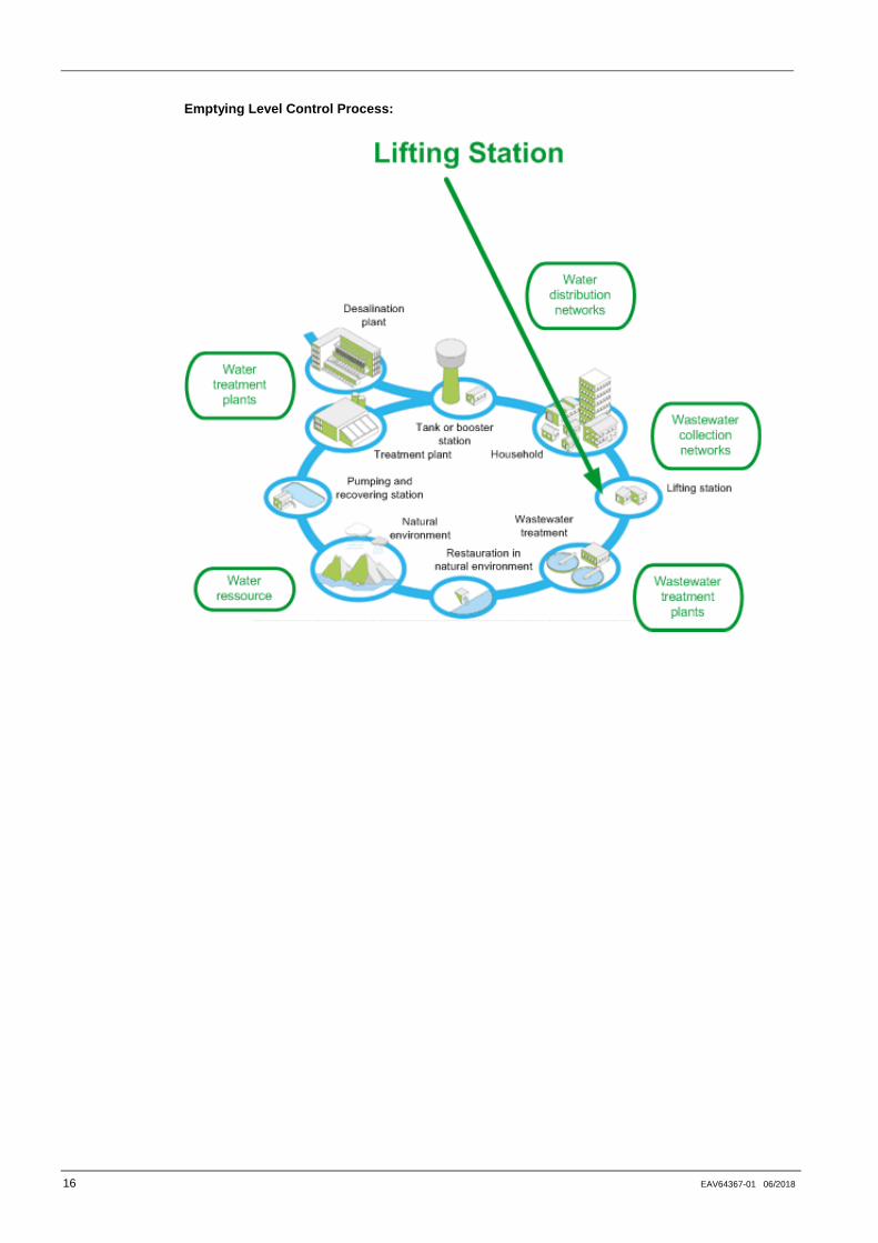
Application example for Water and Waste Water, where Level Control can be used depending of the Level Control mode:
Filling Level Control Process:
16 EAV64367-01 06/2018
Emptying Level Control Process:

EAV64367 01 17
Multi-Pump System Architectures
About Multi-Pump System Architectures
Several Multi-Pump System Architectures exist in process industry. Altivar Process ATV600 drives can be used in several architectures.
Supported Multi-Pump Architectures
The following table shows the Altivar Process ATV600 capabilities for integration into Multi-Pump Architectures:
Single Drive Multiple Drives Multiple Drives & Service continuity
This architecture can be found on simple installations. It provides basic control of the complete installation with a single drive. The Altivar Process ATV600 drive is able to control up to 5 direct on line (or Starter controlled) pumps in addition to the variable speed one.
This architecture can be found in advanced installations. It provides advanced control of the complete installation including all the variable speed drives. The Master drive can control up to 5 Slaves through Multi-Drive Link technology. In Multiple Drives architecture, sensors are wired to the Master (continuous black line in the schema) NOTE: Altivar Process ATV600 drives must be linked together through a Dual Port Ethernet fieldbus module (VW3A3721) plugged on each Altivar Process ATV600.
This architecture can be found in advanced installations where service continuity is needed. It provides advanced control of the complete installation including all the variable speed drives. The drives on the installation can act as Master, Master or Slave, or Slave only through Multi-Drive Link technology. In Multiple Drives & Service Continuity, sensors are wired to the Master and to the Redundant Master (continuous and dotted black line). NOTE: Altivar Process ATV600 drives must be linked together through a Dual Port Ethernet fieldbus module (VW3A3721) plugged on each Altivar Process ATV600.

18 EAV64367-01 06/2018
Optimized Level Control
About Optimized Level Control
This strategy defines the right number of pumps to start and the optimal speed which corresponds to the minimum energy consumed by the pumps during a filling or emptying process. The advantage of this strategy is that the pumps are always running at the optimal point during the filling and emptying process.
To operate at optimal System Working Point (System BEP), it is needed to indicate static head of the system by configuring [Min Delivery Heigt] LCdJ and [Max Delivery Heigt] LCdk
• If delivery height is not specified, system will work at “pump BEP” instead of “system BEP”.
• If only one of delivery height min or max is specified, the other one will be calculated taking into account estimation of the height of the tank deduced from sensor and tank configuration.
• When delivery height is constant whatever the tank level is, both min and max delivery heights must be specified.
Start / Stop Levels
In optimized level control, start and stop level have to be configured on levels on which the first pump start and last pump will stop with [Level 1st Pump Start] LRL1 and [Level 1st Pump Stop] LPL1.
The following figure shows the configuration of the start and stop level for an emptying process:
EAV64367 01 19
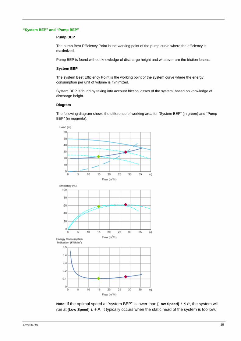
“System BEP” and “Pump BEP”
Pump BEP
The pump Best Efficiency Point is the working point of the pump curve where the efficiency is maximized.
Pump BEP is found without knowledge of discharge height and whatever are the friction losses.
System BEP
The system Best Efficiency Point is the working point of the system curve where the energy consumption per unit of volume is minimized.
System BEP is found by taking into account friction losses of the system, based on knowledge of discharge height.
Diagram
The following diagram shows the difference of working area for “System BEP” (in green) and “Pump BEP” (in magenta):
Note: If the optimal speed at “system BEP” is lower than [Low Speed] LSP, the system will run at [Low Speed] LSP. It typically occurs when the static head of the system is too low.

20 EAV64367-01 06/2018
Disturbance Flow Compensation
In Optimized Level Control strategy, disturbance flow is compensated by delivering a minimum flow depending on the estimated disturbance flow. Then the system working point will be a compromise between energy optimization and covering of disturbance flow.
Disturbance flow is estimated from:
• Tank level measured by the pressure or level sensor
• Tank volume
• Installation flow (measured or estimated)

EAV64367 01 21
Part II Application Description
What is in This Part?
This part contains the following topics:
Application Description ............................................................................................................... 22 Wiring ......................................................................................................................................... 24

22 EAV64367-01 06/2018
Application Description
Introduction
This Application Note describes an emptying level control application with 3 Altivar Process ATV600 variable speed drives.
The following parts of this Application Note describe the commissioning procedure for this architecture.
Application Description
The architecture used as example for this application note is the following:
• A tank with a useful height of 5m.
• 3 Altivar Process ATV600 variable speed drives connected through MultiDrive Link:
o One drive is configured as master only,
o The two other drives are redundant master (Master or Slave). One by one, one of them will act as master if the current drive acting as master is not available.
• 3 Ethernet/IP / ModbusTCP fieldbus modules, VW3A3721.
• 3 Pumps and their associated electrical motors.
• 3 Level sensors (4-20mA, 0-10m)
The following figure shows the water architecture used in this application note:
Motor Characteristics
The following table gives the motor characteristics used in this application.
You can write the value for your application on the Customer Value column
Parameter Application Note Value Customer Value Motor standard 50 Hz Nominal power 5.5 kW Nominal voltage 400 Vac Nominal current 11.20 A Nominal frequency 50.0 Hz Nominal speed 2,930 rpm

EAV64367 01 23
Pump Characteristics
The following table gives the pump characteristics used in this application.
You can write the value for your application on the Customer Value column
Point Application Note Value Customer Value
Flow (m3/h)
Head (bar)
Power (kW)
Flow Head Power
1 15.4 4.60 3.79 2 21.0 4.40 4.42 3 37.8 3.38 5.82 4 41.5 3.00 5.97 5 45.5 2.52 6.12 BEP 32.2 3.82 5.47
The following pump curve shows the selected points for this Application Note:

24 EAV64367-01 06/2018
Wiring
What is in This Chapter?
The following part of this application Note describes the wiring procedure for this architecture
The following table gives the range value according to the sensor type:
You can write the value for your application on the Customer Value column
Analog Input
Sensor Range Value
Application Note Customer Value
Sensor Process Sensor Process AI3 Level Sensor 4-20 mA
0 – 10 m 0 – 10 m
EAV64367 01 25
Part III Prerequisites
Introduction
This part describes the initial steps to do before configuring the Level Control application.
The parameter values given in this part correspond to the architecture selected for this Application Note.
NOTE: Settings may vary according to the architecture needs.
NOTE: Before starting the drive configuration, verify that the drive is reset to factory settings.
What is in This Part?
This part contains the following topics:
Application Selection .................................................................................................................. 26 Motor Configuration .................................................................................................................... 27 High and Low Speed Configuration ............................................................................................ 28 System Units Customization ....................................................................................................... 29 Command and Reference .......................................................................................................... 30 Ethernet Settings ........................................................................................................................ 31 Pump Characteristics ................................................................................................................. 33 Flow Estimation .......................................................................................................................... 35

26 EAV64367-01 06/2018
Application Selection
Overview
The macro-configuration menu allows you to select the appropriate application functions.
This selection gives access to the dedicated functions and associated parameters.
Step-by-Step Configuration
The following table gives the step-by-step configuration of the application selection parameter to be performed on each drive used in this application:
Step Action 1 Go to [Complete Settings] CST [Macro Configuration] MCR menu
2 Set [Application Selection] APPT to [Pump Level Control] LEVEL
EAV64367 01 27
Motor Configuration
Overview
The motor parameters must be set to allow optimized motor control performance.
The parameters have to be entered according to the motor nameplate.
Step-by-Step Configuration
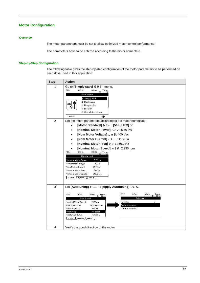
The following table gives the step-by-step configuration of the motor parameters to be performed on each drive used in this application:
Step Action 1 Go to [Simply start] SYS- menu.
2 Set the motor parameters according to the motor nameplate:
• [Motor Standard] bFr : [50 Hz IEC] 50 • [Nominal Motor Power] nPr: 5.50 kW • [Nom Motor Voltage] unS: 400 Vac • [Nom Motor Current] nCr : 11.20 A • [Nominal Motor Freq] FrS: 50.0 Hz • [Nominal Motor Speed] nSP: 2,930 rpm
3 Set [Autotuning] tun to [Apply Autotuning] YES.
4 Verify the good direction of the motor
28 EAV64367-01 06/2018
High and Low Speed Configuration
Overview
It is advisable to configure a low speed of the pump to respect the operating speed limits of the pump.
Step-by-Step Configuration
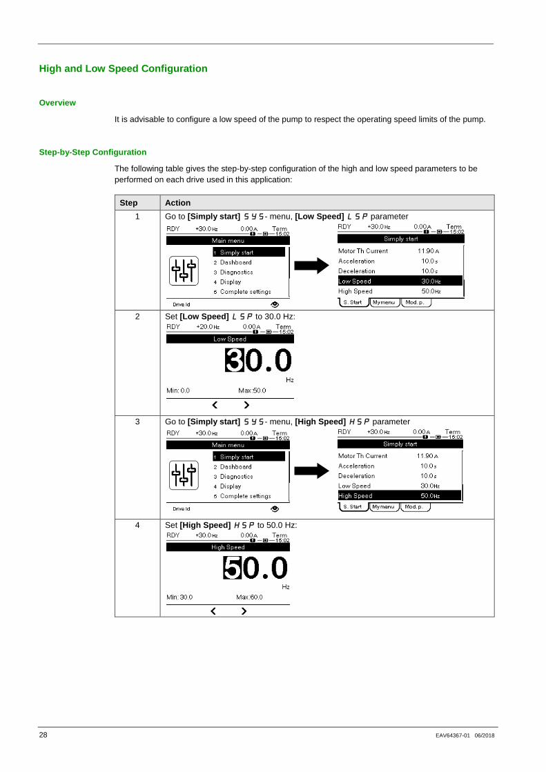
The following table gives the step-by-step configuration of the high and low speed parameters to be performed on each drive used in this application:
Step Action 1 Go to [Simply start] SYS- menu, [Low Speed] LSP parameter
2 Set [Low Speed] LSP to 30.0 Hz:
3 Go to [Simply start] SYS- menu, [High Speed] HSP parameter
4 Set [High Speed] HSP to 50.0 Hz:
EAV64367 01 29
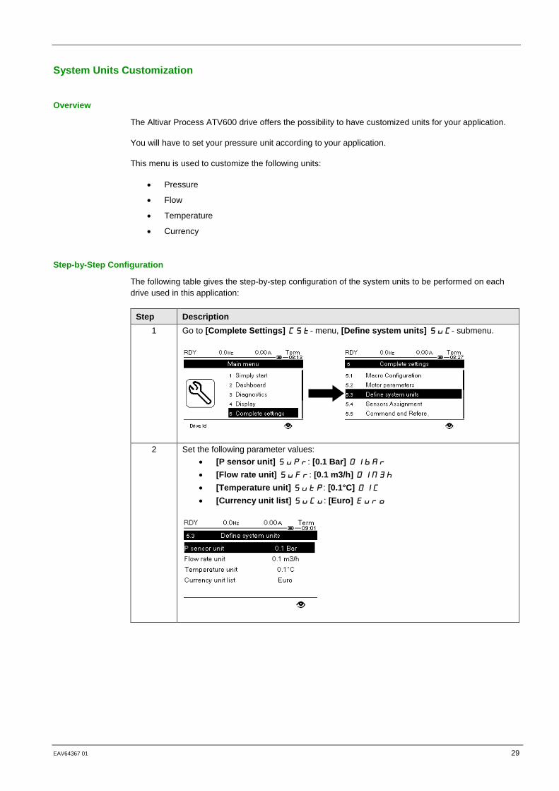
System Units Customization
Overview
The Altivar Process ATV600 drive offers the possibility to have customized units for your application.
You will have to set your pressure unit according to your application.
This menu is used to customize the following units:
• Pressure
• Flow
• Temperature
• Currency
Step-by-Step Configuration
The following table gives the step-by-step configuration of the system units to be performed on each drive used in this application:
Step Description 1 Go to [Complete Settings] CSt- menu, [Define system units] SuC- submenu.
2 Set the following parameter values: • [P sensor unit] SuPr: [0.1 Bar] 01bAr • [Flow rate unit] SuFr: [0.1 m3/h] 01M3h • [Temperature unit] SutP: [0.1°C] 01C • [Currency unit list] SuCu: [Euro] Euro
30 EAV64367-01 06/2018
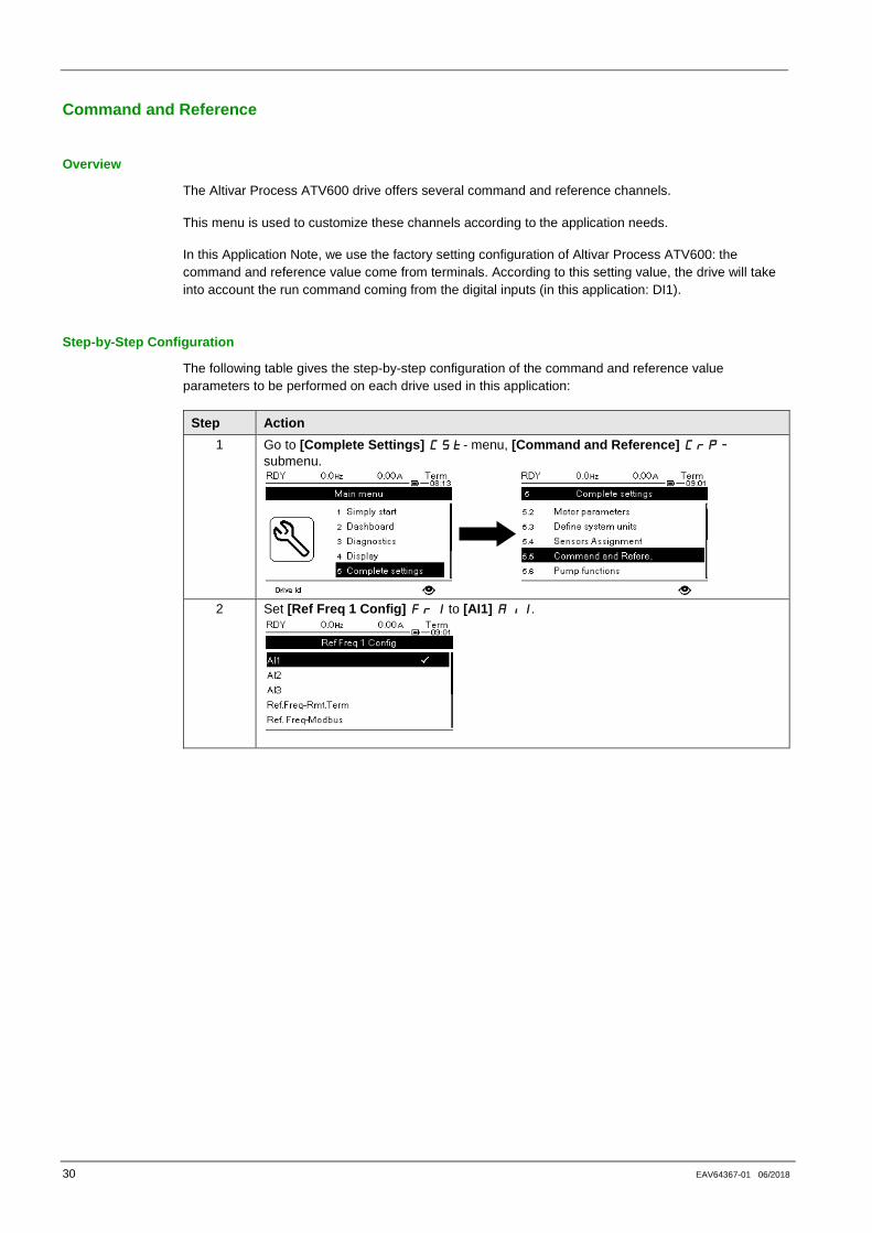
Command and Reference
Overview
The Altivar Process ATV600 drive offers several command and reference channels.
This menu is used to customize these channels according to the application needs.
In this Application Note, we use the factory setting configuration of Altivar Process ATV600: the command and reference value come from terminals. According to this setting value, the drive will take into account the run command coming from the digital inputs (in this application: DI1).
Step-by-Step Configuration
The following table gives the step-by-step configuration of the command and reference value parameters to be performed on each drive used in this application:
Step Action 1 Go to [Complete Settings] CSt- menu, [Command and Reference] CRP-
submenu.
2 Set [Ref Freq 1 Config] FR1 to [AI1] AI1.

EAV64367 01 31
Ethernet Settings
Overview
MultiDrive Link feature of Altivar Process ATV600, equipped with VW3A3721 Ethernet modules, allows controlling the drives of your application using an Ethernet link between your drives.
The drives of an application have to be on the same Ethernet network.
NOTE: The Ethernet settings configuration can also be done automatically using a DHCP or a BOOTP server like a PLC.
Step-by-Step Configuration
The following table gives the step-by-step configuration for the Ethernet settings to be performed on each drive used in this application:
Step Action 1 Go to [Communication] COM [Comm parameters] CMP [Eth Module Config]
ETO menu
2 On drive 1, configure the Ethernet settings:
• Set [ETH Option IP Mode] IM10 to
[Fixed] MANU, • Set [IP address] to 192.168.0.10 • Set [Mask] to 255.255.255.0 • Set [Gateway] to 0.0.0.0
3 On drive 2, configure the Ethernet settings:
• Set [ETH Option IP Mode] IM10 to
[Fixed] MANU, • Set [IP address] to 192.168.0.11 • Set [Mask] to 255.255.255.0 • Set [Gateway] to 0.0.0.0

32 EAV64367-01 06/2018
Step Action 4 On drive 3, configure the Ethernet settings:
• Set [ETH Option IP Mode] IM10
to [Fixed] MANU, • Set [IP address] to 192.168.0.12 • Set [Mask] to 255.255.255.0 • Set [Gateway] to 0.0.0.0
5 Restart the drives to take into account the Ethernet settings.

EAV64367 01 33
Pump Characteristics
Overview
In order to use the Level Control Optimized, you have to configure the pump characteristics.
For Level Control Optimized, we use the Power, Head and Flow characteristics. These data are supplied by the pump manufacturer and are necessary to know the performances of a pump at a given speed.
For further information, you can refer to the ATV600 Programming Manual.
Step-by-Step Configuration
The following table gives the step-by-step configuration for the pump characteristics to be performed on each drive used in this application:
Step Action 1 Go to [Complete settings] CST [Pump functions] PFT [Pump
characteristics] PCR
2 • Set [Mode] PCM to [PHQ] PHQ
3 • Set [Pump Speed] PCSP to 2900 rpm
4 • Set [Flow at BEP] PCBQ to 32.2 m3/h
• Set [Head BEP] PCBH to 3.8 bar • Set [Power BEP] PCBP to 5.47 kW
34 EAV64367-01 06/2018
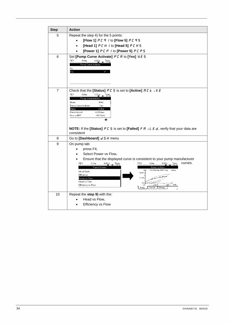
Step Action 5 Repeat the step 4) for the 5 points:
• [Flow 1] PCQ1 to [Flow 5] PCQ5 • [Head 1] PCH1 to [Head 5] PCH5 • [Power 1] PCP1 to [Power 5] PCP5
6 Set [Pump Curve Activate] PCA to [Yes] YES
7 Check that the [Status] PCS is set to [Active] ACTIVE
NOTE: If the [Status] PCS is set to [Failed] FAILED, verify that your data are consistent
8 Go to [Dashboard] DSH menu 9 On pump tab:
• press F4, • Select Power vs Flow, • Ensure that the displayed curve is consistent to your pump manufacturer
curves.
10 Repeat the step 9) with the: • Head vs Flow, • Efficiency vs Flow

EAV64367 01 35
Flow Estimation
Overview
This function allows the estimation of the flow of a pump using the predefined pump curves HQ or PQ entered by the user.
It is necessary to calibrate the function with:
• [Power Dynamic Gain] PEG: to define a correction gain applied to the estimated power from the drive.
• [Power Static Offset] PEO: to define a correction offset applied to the estimated power from the drive.
To calibrate the function, use the following method:
• Correction according to the nominal pump curve.
Step-by-step Configuration
The following table gives the step-by-step configuration for the Flow Estimation to be performed on each drive used in this application, one by one:
Step Action 1 Go to [Complete settings] CST [Pump functions] PFT [Flow estimation]
SFE 2 Set [Flow Estimation Mode] FEM to [PQ] PQ 3 On a stabilized system, run the pump at its minimum speed. 4 Adjust, if necessary the [Power Static
Offset] PEO in order to have the point on the curve using the [Power vs Flow] curve in the [Dashboard] dSH menu.
5 Run the pump at its nominal speed. 6 Adjust, if necessary the [Power Dynamic
Gain] PEG in order to have the point on the curve using the [Power vs Flow] curve in the [Dashboard] dSH menu.
36 EAV64367-01 06/2018
Part IV MultiPump Configuration
Introduction
This part describes the steps to perform in order to use the MultiDrive Link feature of Altivar Process ATV600.
The parameter values given in this part correspond to the Multi Drives architecture selected for this Application Note.
NOTE: Settings may vary according to the architecture needs.
What is in This Part?
This part contains the following topics:
Pump System Architectures ....................................................................................................... 37 MultiDrive Link Configuration ..................................................................................................... 38
EAV64367 01 37
Pump System Architectures
Overview
The Altivar Process ATV600 drive can be used in several pump architectures.
This menu is used to select and configure one of the following architectures:
• Single Drive: one Altivar Process ATV600 and up to 5 fixed speed pumps.
• Multi Drives: one Master Altivar Process ATV600 and up to 5 Slaves Altivar Process ATV600.
• Multi Masters: Up to 6 Altivar Process ATV600 that can act as Masters or Slaves.
In this Application Note, the selected architecture is Multi Masters.
Step-by-Step Configuration
The following table gives the step-by-step configuration for the selection of Pump System Architecture to be performed on each drive used in this application:
Step Action 1 Go to [Complete settings] CST [Pump functions] PFT [Level Control]
LVL [System architecture] MPQ menu
2 Set [Pump System Architecture] MPSA to [Multi Masters] NVSDr
38 EAV64367-01 06/2018
MultiDrive Link Configuration
Overview
The MultiDrive Link needs to be configured on each drive to define if the device in the application acts as Master or Slave.
In this Application Note, one drive acts as Master and the two other drives act as Master or Slave.
There are two different step-by-step configurations:
• One for the master drive (primary master);
• One for each redundant master.
In this application, no drive is acting as slave only.
Master Step-by-Step Configuration
The following table gives the step-by-step configuration of the MultiDrive Link on Primary Master:
Step Action 1 Go to [Complete settings] CST [Pump functions] PFT [Level Control] LVL
[System architecture] MPQ [Multidrive Config] MPVC menu
2 Configure the parameters:
• Set [M/P Device Role] MPDT to [Master Only] MAST1,
• Set [Nb of Devices] MPGN to 3, • Set [M/P Device ID] MGID to 1.
EAV64367 01 39
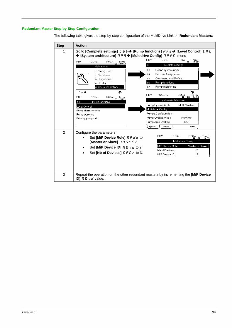
Redundant Master Step-by-Step Configuration
The following table gives the step-by-step configuration of the MultiDrive Link on Redundant Masters:
Step Action 1 Go to [Complete settings] CST [Pump functions] PFT [Level Control] LVL
[System architecture] MPQ [Multidrive Config] MPVC menu
2 Configure the parameters:
• Set [M/P Device Role] MPDT to [Master or Slave] MASTE2,
• Set [M/P Device ID] MGID to 2, • Set [Nb of Devices] MPGN to 3.
3 Repeat the operation on the other redundant masters by incrementing the [M/P Device ID] MGID value.

40 EAV64367-01 06/2018
Part V Level Control Configuration
Introduction
This part describes the steps to do in order to configure the Level Control application.
The parameter values given in this part correspond to the architecture selected for this Application Note.
NOTE: Settings may vary according to the architecture needs.
What is in This Part?
This part contains the following topics:
Level Control Mode Selection .................................................................................................... 41 Sensor Configuration ................................................................................................................. 42 Tank Height Configuration ......................................................................................................... 44 Level Control Strategy Configuration ......................................................................................... 45 Start / Stop Levels Configuration ............................................................................................... 47 Delivery Height Configuration .................................................................................................... 48

EAV64367 01 41
Level Control Mode Selection
Overview
Two Level Control mode selections can be selected on Altivar Process ATV600, filling or emptying mode.
In this Application Note, the Level Control mode selected is emptying.
Step-by-Step Configuration
The following table gives the step-by-step configuration of the Level Control mode selection to be performed on the primary master drive and the redundant master drives.
Step Action 1 Go to [Complete settings] CST [Pump functions] PFT [Level control] LVL
menu [Level Control] LCC tab:
2 Set [LevelCtrl Mode] LCM to [Emptying] EMPTY:

42 EAV64367-01 06/2018
Sensor Configuration
Overview
Altivar Process ATV600 drive supports three sensor types to manage the tank level in a Level Control application:
• Level switches
• Level sensors
• Pressure sensors
In this Application Note, the sensor used is a Level Sensor with the following specifications: 4-20mA for 0-10m.
Sensor Type Configuration
On the primary master drive and the redundant master drives, configure the sensor type as below:
Step Action 1 Go to [Complete settings] CST [Pump functions] PFT [Level control] LVL
menu [Level Control] LCC tab
2 Set [LevelCtrl Sensor Type] LCNt to [Level Sensor] LEVEL.

EAV64367 01 43
Sensor Assignment and Configuration
For the primary master drive and the redundant master drives, the following table gives the step-by-step configuration of the sensor used:
Step Action 1 Go to [Complete settings] CST [Pump functions] PFT menu [Level control]
LVL [Level Control] LCC tab
2 Set [Level Sensor Assign] to [AI3]
3 In [AI3 Configuration] LCA3 configure the following parameters:
• Set [AI3 Type] AI3T to [Current] 0A, • Set [AI3 Min. Value] CRL3 to 4.0 mA, • Set [AI3 Max Value] CRH3 to 20 mA, • Set [AI3 Lowest Process] AI3J to 0, • Set [AI3 Highest Process] AI3K to
1000. NOTE: The lowest and highest process values entered correspond to the minimum and maximum values of the sensor. As the sensor type used is a level sensor, the unit here is in 0.01m.

44 EAV64367-01 06/2018
Tank Height Configuration
Overview
The tank height has to be configured to establish a correspondence between the sensor configuration and the real tank height.
In this Application Note, the tank height is 5m which is lower than the maximum value of the level sensor used.
Step-by-Step Configuration
The following table gives the step-by-step configuration of the tank height configuration to be performed on the primary master drive and the redundant master drives:
Step Action 1 Go to [Complete settings] CST [Pump functions] PFT [Level control] LVL
menu [Level Control] LCC tab
2 Configure the height of the tank:
• Set [Empty Tank Level] LCTJ to 0.00 m, • Set [Full Tank Level] LCTK to 5.00 m.
EAV64367 01 45
Level Control Strategy Configuration
Overview
Altivar Process ATV600 offers 3 different strategies for Level Control applications:
• [Switches]TRAD strategy, based on level switches.
• [Standard]BASIC strategy, based on analog level.
• [Energy Optimized] ADV strategy, based on analog level and installation flow.
In this Application Note, the [Energy Optimized ] ADV strategy is used as analog level and installation flow are available.
This strategy consists in the internal calculation of the optimal velocity profile which corresponds to the minimum energy consumed by the system during a filling or emptying process. The system runs at an optimal working point during the filling or emptying process.
To perform this strategy, following data are required:
• Validated pump curve characteristics (Hn, Pn, Qn at nominal speed). The pump curves must be configured previously in the [Pump characteristics] PCr- menu; pump parameterization is valid if the pump curve status [Status] PCS equals to [ACTIVE] ACtiVE.
• Estimated or measured installation flow.
• The volume of the tank [Tank Volume] LCtV.
• The minimum delivery height of the system [Min Delivery Height]LCdJ and the maximum delivery height of the system [Max Delivery Height] LCDk.
Note: In the case of a multidrive architecture, if the installation flow is not measured it can be estimated from the pump flows themselves generally estimated by each drive from pump curves.
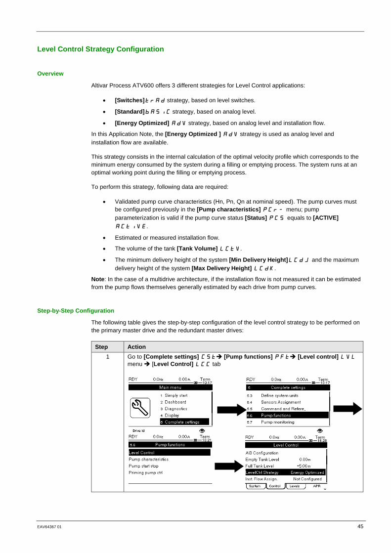
Step-by-Step Configuration
The following table gives the step-by-step configuration of the level control strategy to be performed on the primary master drive and the redundant master drives:
Step Action 1 Go to [Complete settings] CST [Pump functions] PFT [Level control] LVL
menu [Level Control] LCC tab

46 EAV64367-01 06/2018
Step Action 2 Set [LevelCtrl Strategy] LCST to [Energy Optimized] ADV.
3 Set [Inst. Flow Assign.] FS1A to [Est. System Flow] SLSF

EAV64367 01 47
Start / Stop Levels Configuration
Overview
In optimized level control strategy, only two levels must be configured:
• The level on which the first pump starts. It corresponds to [Level 1st Pump Start] LRL1
parameter.
• The level on which the last pump stops. It corresponds to [Level 1st Pump Stop] LPL1
parameter.
The unit of these parameters is in percentage of the total tank height.
Step-by-Step Configuration
The following table gives the step-by-step configuration of the start / stop levels to be performed on the primary master drive and the redundant master drives:
Step Action 4 Go to [Complete settings] CST [Pump functions] PFT [Level control] LVL
menu [Level Settings] LCL tab
5 Configure the start and stop level:
• Set [Level 1st Pump Start] LRL1 to 30%, • Set [Level 1st Pump Stop] LPL1 to 20%.
48 EAV64367-01 06/2018
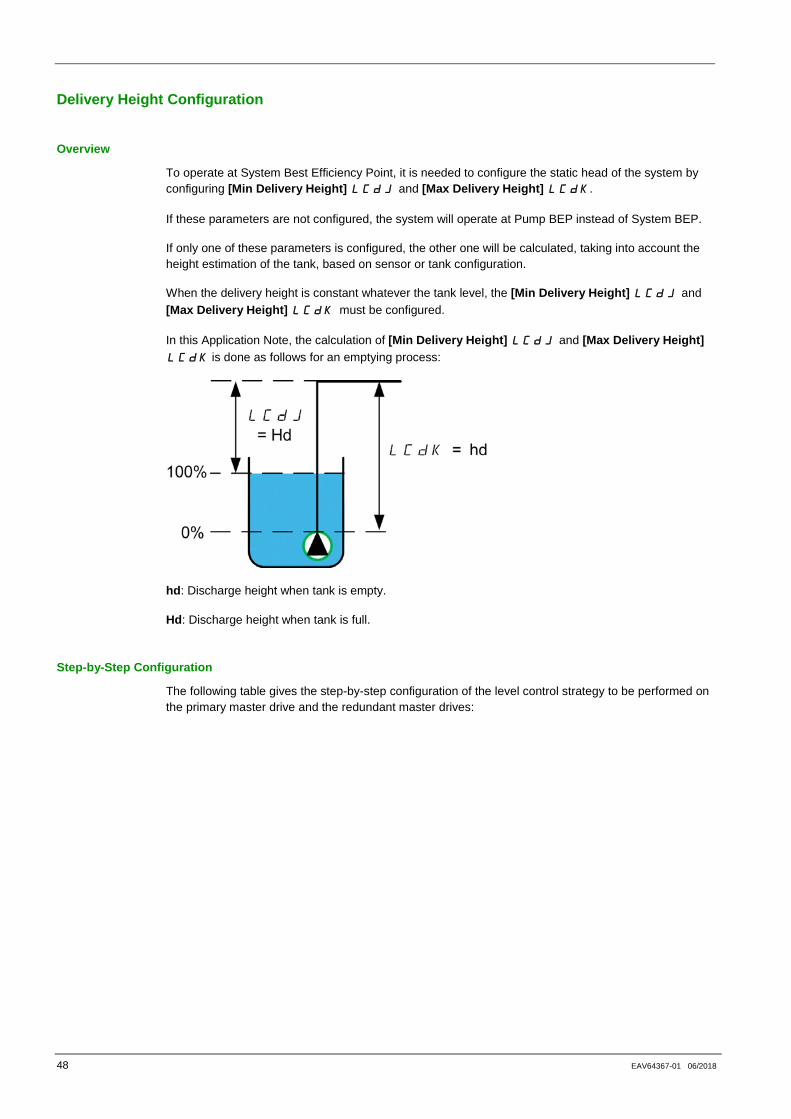
Delivery Height Configuration
Overview
To operate at System Best Efficiency Point, it is needed to configure the static head of the system by configuring [Min Delivery Height] LCdJ and [Max Delivery Height] LCDk.
If these parameters are not configured, the system will operate at Pump BEP instead of System BEP.
If only one of these parameters is configured, the other one will be calculated, taking into account the height estimation of the tank, based on sensor or tank configuration.
When the delivery height is constant whatever the tank level, the [Min Delivery Height] LCdJ and [Max Delivery Height] LCDk must be configured.
In this Application Note, the calculation of [Min Delivery Height] LCdJ and [Max Delivery Height] LCDk is done as follows for an emptying process:
hd: Discharge height when tank is empty.
Hd: Discharge height when tank is full.
Step-by-Step Configuration
The following table gives the step-by-step configuration of the level control strategy to be performed on the primary master drive and the redundant master drives:

EAV64367 01 49
Step Action 1 Go to [Complete settings] CST [Pump functions] PFT [Level control] LVL
menu [Level Control] LCC tab
2 Configure the delivery height:
• Set [Min Delivery Height] LCdJ to 0.01 m, • Set [Max Delivery Height] LCDk to 5.00 m.

50 EAV64367-01 06/2018
Part VI Additional Parameters
Introduction
This part describes the additional steps that can be performed to optimize the Optimized Level Control application behavior.
In factory settings configuration, these parameters allow standard working on the application.
The parameter values given in this part are given as example with their effects on the application.
NOTE: Settings may vary according to the architecture needs.
What is in This Part?
This part contains the following topics:
MultiDrive Link - Optional Wiring ................................................................................................ 51 MultiDrive Link – Error & Warning Handling ............................................................................... 54 System Architecture – Pumps Configuration .............................................................................. 57 System Architecture – Pump Cycling Parameters ..................................................................... 58 Level Control – Number of Pumps ............................................................................................. 59 Level Control – Random Factor ................................................................................................. 60 Level Control – Error & Warning Handling ................................................................................. 61
EAV64367-01 51
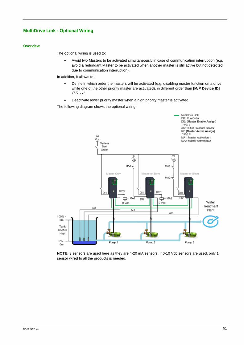
MultiDrive Link - Optional Wiring
Overview
The optional wiring is used to:
• Avoid two Masters to be activated simultaneously in case of communication interruption (e.g. avoid a redundant Master to be activated when another master is still active but not detected due to communication interruption).
In addition, it allows to:
• Define in which order the masters will be activated (e.g. disabling master function on a drive while one of the other priority master are activated), in different order than [M/P Device ID] MGID
• Deactivate lower priority master when a high priority master is activated.
The following diagram shows the optional wiring:
NOTE: 3 sensors are used here as they are 4-20 mA sensors. If 0-10 Vdc sensors are used, only 1 sensor wired to all the products is needed.

52 EAV64367-01 06/2018
Step-by-Step Configuration on Primary Master
The following table gives the step-by-step configuration for the optional wiring on Primary Master:
Step Action 1 Go to [Complete settings] CST [Pump functions] PFT [Level Control] LVL
[System architecture] MPQ [Multidrive Config] MPVC menu
2 Set [Master Active Assign] MPMA to [R2]
R2

EAV64367-01 53
Step-by-Step Configuration on Redundant Master
The following table gives the step-by-step configuration for the optional wiring on Redundant Master:
Step Action 1 Go to [Complete settings] CST [Pump functions] PFT [Level Control] LVL
[System architecture] MPQ [Multidrive Config] MPVC menu
2 • Set [Master Enable Assign] MPME to [DI2] LI2
• Set [Master Active Assign] MPMA to [R2] R2

54 EAV64367-01 06/2018
MultiDrive Link – Error & Warning Handling
Overview
It is possible to configure the response to errors that the drives can detect on the MultiDrive Link architecture.
It is also possible to configure the MultiDrive Link communication timeout according to the network load of the application.
By default, these error responses are set to ramp stop to avoid water hammer effect.
In this configuration example, the error responses are changed to freewheel stop and the timeout is set to 0.20 s.
A [MultiDrive Link Error] MDLF error is active if the MultiDrive Link architecture is not consistent (several Masters, several Slaves with same ID) at run command. The drive response to a [MultiDrive Link Error] MDLF is set with [MultiDrive ErrorResp] MDLB parameter.
The [M/P Device Error] MPDF error can be active only on a device which acts as a Slave. The drive response to a [M/P Device Error] MPDF is set with [M/P Device ErrorResp] MPDB parameter.
Master Configuration
The following table gives the step-by-step configuration on Master for the MultiDrive Link error and warning:
Step Action 1 Go to [Complete settings] CST [Pump functions] PFT [Level Control] LVL
[System architecture] MPQ [Multidrive Config] MPVC menu, [MultiDrive ErrorResp] MdLb parameter:
2 Set [MultiDrive ErrorResp] MDLB to [Freewheel Stop] NST

EAV64367-01 55
Step Action 3 Set the [MDL Comm Timeout] MLTO to 0.20 s
Slaves Configuration
The following table gives the step-by-step configuration on Slaves for the MultiDrive Link error and warning:
Step Action 1 Go to [Complete settings] CST [Pump functions] PFT [Level Control] LVL
[System architecture] MPQ [Multidrive Config] MPVC menu, [MultiDrive ErrorResp] MdLb parameter:
2 Set [MultiDrive ErrorResp] MDLB to [Freewheel Stop] NST
3 Set the [MDL Comm Timeout] MLTO to 0.20 s
56 EAV64367-01 06/2018
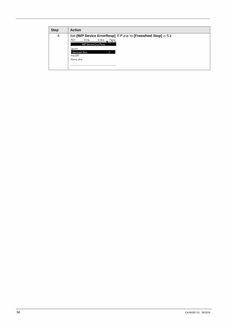
Step Action 4 Set [M/P Device ErrorResp] MPDB to [Freewheel Stop] NST

EAV64367-01 57
System Architecture – Pumps Configuration
Overview
For maintenance purposes, you can interlock a pump locally by activating a digital input.
In this configuration example, a drive will be not available when the digital input DI3 will be inactive.
Step-by-Step Configuration
The following table gives the step-by-step configuration for the Pumps on each drive:
Step Action 5 Go to [Complete settings] CST [Pump functions] PFT [Level control]
LVL [System architecture] MPQ [Pump Configuration] PUMP menu
6 Set [Pump 1 Ready Assign] MPI1 to [DI3] LI3.

58 EAV64367-01 06/2018
System Architecture – Pump Cycling Parameters
Overview
This functionality allows changing the start order of all available pumps in order to manage their wear.
In this configuration example, the cycling mode is based on running time. The available pump with the lowest running time is started first and the running pump with the highest running time is stopped first.
Step-by-Step Configuration
Step Action 1 Go to [Complete settings] CST [Pump functions] PFT [Level control] LVL
[System architecture] MPQ [Pump Configuration] PUMP menu
2 Set [Pump Cycling Mode] MPPC to [Runtime] RTIME

EAV64367-01 59
Level Control – Number of Pumps
Overview
It is possible to have more pumps available than needed in a MultiPump architecture.
This configuration is needed, for example, if you have X pumps declared on the MultiDrive Link architecture but less than X pumps can cover the needs of the Level Control application.
If the number of pumps declared on the MultiDrive Link is the same as the number of pumps used in the Level Control application, this parameter can be set to 0.
In this configuration example, the maximum number of pumps used for the Level Control function is set to 3.
Number of Pumps Configuration
Configure the number of pumps as below:
Step Action 1 On master go to [Complete settings] CST [Pump functions] PFT [Level
control] LVL menu [Level Control] LCC tab
2 Set [LevelCtrl Nb Of Pumps] LCPN to 3
60 EAV64367-01 06/2018
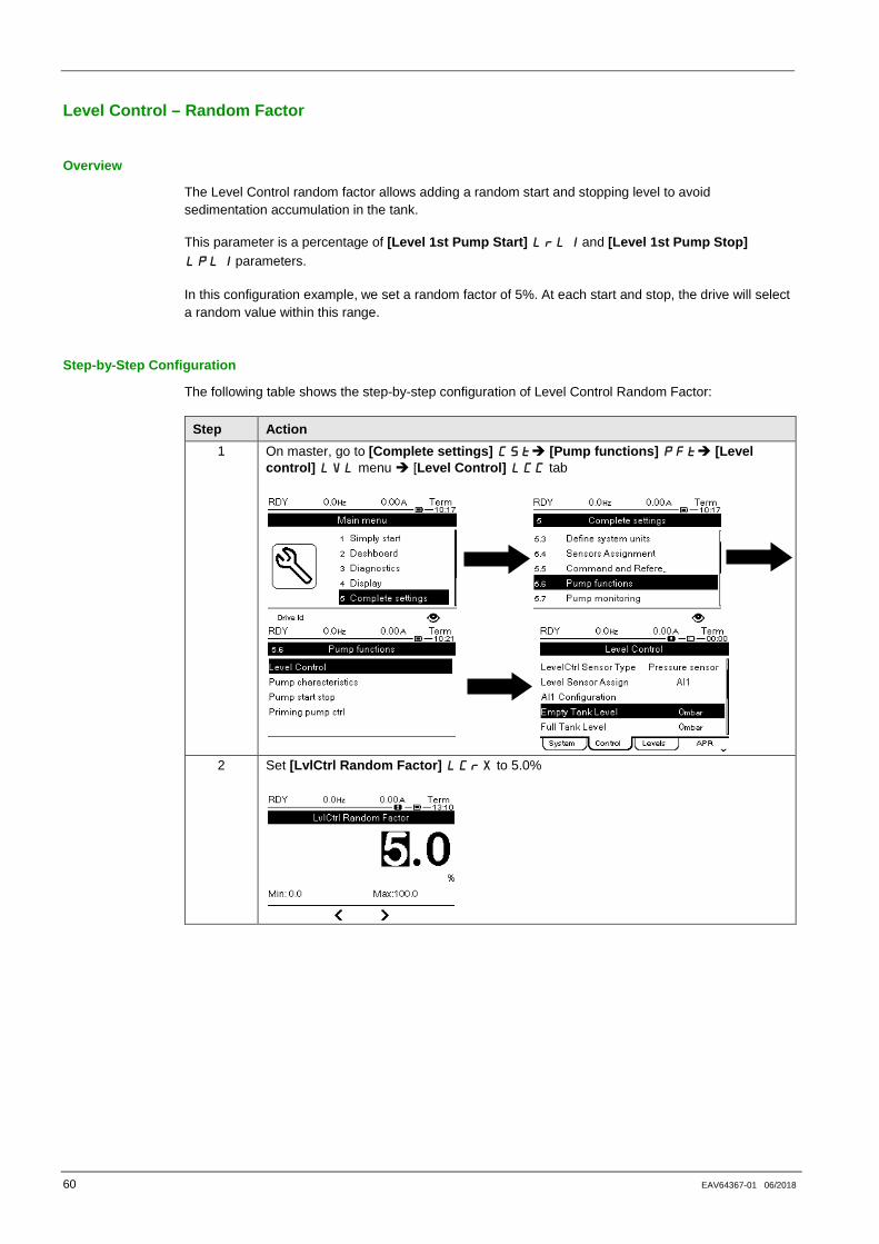
Level Control – Random Factor
Overview
The Level Control random factor allows adding a random start and stopping level to avoid sedimentation accumulation in the tank.
This parameter is a percentage of [Level 1st Pump Start] LRL1 and [Level 1st Pump Stop] LPL1 parameters.
In this configuration example, we set a random factor of 5%. At each start and stop, the drive will select a random value within this range.
Step-by-Step Configuration
The following table shows the step-by-step configuration of Level Control Random Factor:
Step Action 1 On master, go to [Complete settings] CST [Pump functions] PFT [Level
control] LVL menu [Level Control] LCC tab
2 Set [LvlCtrl Random Factor] LCRX to 5.0%
EAV64367-01 61
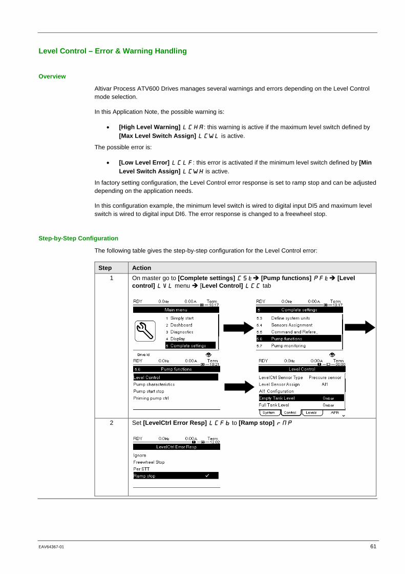
Level Control – Error & Warning Handling
Overview
Altivar Process ATV600 Drives manages several warnings and errors depending on the Level Control mode selection.
In this Application Note, the possible warning is:
• [High Level Warning] LCHA: this warning is active if the maximum level switch defined by [Max Level Switch Assign] LCWL is active.
The possible error is:
• [Low Level Error] LCLF: this error is activated if the minimum level switch defined by [Min Level Switch Assign] LCWH is active.
In factory setting configuration, the Level Control error response is set to ramp stop and can be adjusted depending on the application needs.
In this configuration example, the minimum level switch is wired to digital input DI5 and maximum level switch is wired to digital input DI6. The error response is changed to a freewheel stop.
Step-by-Step Configuration
The following table gives the step-by-step configuration for the Level Control error:
Step Action 1 On master go to [Complete settings] CST [Pump functions] PFT [Level
control] LVL menu [Level Control] LCC tab
2 Set [LevelCtrl Error Resp] LCFB to [Ramp stop] RMP
62 EAV64367-01 06/2018
Part VII Parameters Table
Introduction
The part shows all the parameters modified to allow configuration of the Level Control application.
What is in This Part?
This part contains the following topics:
Parameter Table ........................................................................................................................ 63

EAV64367-01 63
Parameter Table
Parameter List Used in this Application Note
The following table shows all the parameters modified to allow configuration of the Level Control application.
You can write the value for your application on the Customer value column.
You can use the SoMove Altivar Process ATV600 : DTM to store the configuration.
Menu Parameter Application Note Setting
Customer values
Drive 1 : Master
Drive 2 : Master or Slave
Drive 3 : Master or Slave
[Simply start] [Motor Standard] BFR
[50 Hz IEC] 50
[Nominal Motor Power] NPR
5.50 kW
[Nom Motor Voltage] UNS
400 Vac
[Nom Motor Current] NCR
11.20 A
[Nominal Motor Freq] FRS
50.0 Hz
[Nominal Motor Speed] NSP
2,930 rpm
[Motor Th Current] ITH
11.20 A
[Acceleration] ACC 10.0 s [Deceleration] DEC 10.0 s [Low Speed] LSP 30.0 Hz [High Speed] HSP 50.0 Hz
[Macro Configuration]
[Application Selection] APPT
[Pump Level Control] LEVEL
[Define system units]
[P sensor unit] SUPR
[0.1 Bar] 01BAR
[Flow rate unit] SUFR
[0.1 m3/h] 01M3H
[Sensors Assignment]
[Ref Freq 1 Config] FR1
[AI1] AI1
[Eth Module Config]
[ETH Option IP Mode] [Fixed] MANU [IP address] 192.168.0.xx(1) [Mask] 255.255.255.0(1)
[Pump characteristics]
[Mode] PCM [PHQ] PHQ [Pump Speed] PCSP 2900 rpm (2) [Flow at BEP] PCBQ 32.2(2) [Head BEP] PCBH 3.82(2) [Power BEP] PCPB 5.47(2) [Flow 1] PCQ1… [Flow 5] PCQ5
15.4(2) 21.0(2) 37.8(2) 41.5(2) 45.5(2)

64 EAV64367-01 06/2018
Menu Parameter Application Note Setting
Customer values
Drive 1 : Master
Drive 2 : Master or Slave
Drive 3 : Master or Slave
[Head 1] PCH1… [Head 5] PCH5
4.60(2) 4.40(2) 3.38(2) 3.00(2) 2.52(2)
[Power 1] PCP1…[Power 5] PCP5
3.79(2) 4.42(2) 5.82(2) 5.97(2) 6.12(2)
[Level Control] [Pump System Archi] MPSA
[Multi Masters] NVSDr
[M/P Device Role] MPDT
[Master Only] MAST1, [Master or Slave] MASTE2 and [Master or Slave] MASTE2 (1)
[Nb of Devices] MPGN
3
[M/P Device ID] MGID
1,2 and 3 (1)
[MultiDrive ErrorResp] MDLB
[Freewheel Stop] NST
[MDL Comm Timeout] MLTO
0.20s
[M/P Device ErrorResp] MPDB
[Freewheel Stop] NST
[Pump Cycling Mode] MPPC
[Runtime] RTIME
[LevelCtrl Mode] LCM [Emptying] EMPTY
[LevelCtrl Nb of Pumps] LCPN
3
[LevelCtrl Sensor Type] LCNT
[Level sensor] LEVeL
[Level Sensor Assign] LCSA
[AI1]AI3
[AI3 Type] AI3T [Current] 0A [AI3 Min. Value] CRL3
4.0 mA
[AI3 Max Value] CRH3
20.0 mA
[AI3 Lowest Process] AI3J
0
[AI3 Highest Process] AI3K
1000
[Empty Tank Level] LCTJ
0.00m
[Full Tank Level] LCTK
5.00m
[Level 1st Pump Start] LRL1
30%

EAV64367-01 65
Menu Parameter Application Note Setting
Customer values
Drive 1 : Master
Drive 2 : Master or Slave
Drive 3 : Master or Slave
[Level 1st Pump Stop] LPL1
20%
[LevelCtrl Strategy] LCST
[Energy Optimized] ADV
[Inst. Flow Assign.] FS1A
[Est. System Flow] SLSF
[Min Delivery Height] LCdJ
0.01 m
[Max Delivery Height] LCDk
5.00 m
[LvlCtrl Random Factor] LCRX
5.0%
[Min Lvl Switch Assign] LCWL
-
[Max Lvl Siwtch Assign] LCWH
-
[LevelCtrl Error Resp] LCFB
[Ramp stop] RMP
NOTE: -(1): Depends on the drive: Master or Slaves. -(2): Supplied by the pump manufacturer.

ATV600_MultiMasters_with_Optimized_Level_Control_EAV64367_01 06/2018
Top Related