


Languages
Pages
Legal

Proportional/Integral/DerivativeControl (2�Loop) Module
Product Data
1
Allen�BradleyProportional/Integral/Derivative Control(2�Loop) Module
(Cat. No. 1771-PD)
Product Data
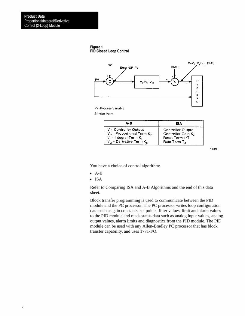
The Proportional/Integral/Derivative Control (2-Loop) Module Assembly(cat. no. 1771-PD) is an intelligent I/O Module that performs closed loopPID control. The PID module is a process controller. It monitors the inputprocess variable, compares the input to the desired set point, and calculatesthe analog output based on the control algorithm programmed in themodule (figure 1). It can be used with a variety of I/O devices that operatein the +4 to +20mA or +1 to +5V DC range.
General Description
Proportional/Integral/DerivativeControl (2�Loop) Module
Product Data
2
Figure 1PID Closed Loop Control
You have a choice of control algorithm:
A-BISA
Refer to Comparing ISA and A-B Algorithms and the end of this datasheet.
Block transfer programming is used to communicate between the PIDmodule and the PC processor. The PC processor writes loop configurationdata such as gain constants, set points, filter values, limit and alarm valuesto the PID module and reads status data such as analog input values, analogoutput values, alarm limits and diagnostics from the PID module. The PIDmodule can be used with any Allen-Bradley PC processor that has blocktransfer capability, and uses 1771-I/O.
Proportional/Integral/DerivativeControl (2�Loop) Module
Product Data
3
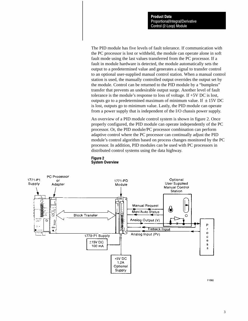
The PID module has five levels of fault tolerance. If communication withthe PC processor is lost or withheld, the module can operate alone in softfault mode using the last values transferred from the PC processor. If afault in module hardware is detected, the module automatically sets theoutput to a predetermined value and generates a signal to transfer controlto an optional user-supplied manual control station. When a manual controlstation is used, the manually controlled output overrides the output set bythe module. Control can be returned to the PID module by a “bumpless”transfer that prevents an undesirable output surge. Another level of faulttolerance is the module’s response to loss of voltage. If +5V DC is lost,outputs go to a predetermined maximum of minimum value. If �15V DCis lost, outputs go to minimum value. Lastly, the PID module can operatefrom a power supply that is independent of the I/O chassis power supply.
An overview of a PID module control system is shown in figure 2. Onceproperly configured, the PID module can operate independently of the PCprocessor. Or, the PID module/PC processor combination can performadaptive control where the PC processor can continually adjust the PIDmodule’s control algorithm based on process changes monitored by the PCprocessor. In addition, PID modules can be used with PC processors indistributed control systems using the data highway.
Figure 2System Overview
Proportional/Integral/DerivativeControl (2�Loop) Module
Product Data
4
The PID module can control one or two PID closed loops. The two loopscan be independent or linked together by an advanced control functionsuch as cascade or decoupling. Expanded loop features can be chosen inaddition to standard features to suit the application. All features areselectable by settings bits in the data table with the exception of the I/Orange, the source of +5V DC, and the fault response to a hardware failure,or loss of +5V DC (which are selected using internal configuration plugs).Write block transfers to the module allow program logic to enable thefollowing features:
Standard Features for Input Conditioning
detect the loss of process variable input
read the process variable at the PC processor
substitute a value calculated by the PC processor for use as the processvariable
take the normalized square root of the process variable
digitally filter the process variable
Standard Control Features
select direct or reverse acting control
download a set point from the PC processor
limit and/or set an alarm on the error signal
perform error dead band (zero crossing)
set an alarm when the error exceeds the dead band
select the A-B or ISA PID algorithm
select error or error squared conditioning of the proportional and/orintegral error
select whether the derivative function operates on the error or theprocess variable
set an alarm on the proportional term
limit and/or set an alarm on the integral term
limit and/or set an alarm on the derivative term
Standard Features for Output Conditioning
limit and/or set an alarm on the PID algorithm output
read the PID algorithm output at the PC processor
Loop Features
Proportional/Integral/DerivativeControl (2�Loop) Module
Product Data
5
override the PID algorithm output from the PC processor
interface directly with a manual control station (bumpless transfer)
hold the PID algorithm output for independent loop tuning
hold the bias/feedforward term for independent loop tuning
download an output bias from the PC processor
Expanded Features
perform scaling on the process variable, set point and/or error
use the tieback as the feedforward input
take the normalized square root of the feedforward input
add a feedforward offset
multiply the feedforward term by a constant
perform lead/lag filtering on the feedforward term
download a feedforward value from the PC processor
cascade the output of loop 1 into the set point of loop 2
decouple the VPID output of loop 1 into the feedforward input of loop 2
The module performs anti-reset wind-up on the integral output term. Whena limit is set on the PID algorithm output, the integral output term isadjusted to compensate for changes in other algorithm output terms.
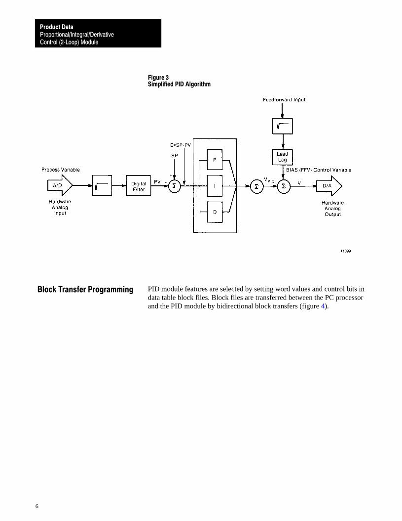
A simplified flow chart of the PID loop algorithm (figure 3) showsselected standard and expanded loop features.
Proportional/Integral/DerivativeControl (2�Loop) Module
Product Data
6
Figure 3Simplified PID Algorithm
PID module features are selected by setting word values and control bits indata table block files. Block files are transferred between the PC processorand the PID module by bidirectional block transfers (figure 4).
Block Transfer Programming
Proportional/Integral/DerivativeControl (2�Loop) Module
Product Data
7
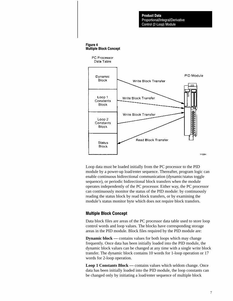
Figure 4Multiple Block Concept
Loop data must be loaded initially from the PC processor to the PIDmodule by a power-up load/enter sequence. Thereafter, program logic canenable continuous bidirectional communication (dynamic/status togglesequence), or periodic bidirectional block transfers when the moduleoperates independently of the PC processor. Either way, the PC processorcan continuously monitor the status of the PID module: by continuouslyreading the status block by read block transfers, or by examining themodule’s status monitor byte which does not require block transfers.
Multiple Block Concept
Data block files are areas of the PC processor data table used to store loopcontrol words and loop values. The blocks have corresponding storageareas in the PID module. Block files required by the PID module are:
Dynamic block — contains values for both loops which may changefrequently. Once data has been initially loaded into the PID module, thedynamic block values can be changed at any time with a single write blocktransfer. The dynamic block contains 10 words for 1-loop operation or 17words for 2-loop operation.
Loop 1 Constants Block — contains values which seldom change. Oncedata has been initially loaded into the PID module, the loop constants canbe changed only by initiating a load/enter sequence of multiple block

Proportional/Integral/DerivativeControl (2�Loop) Module
Product Data
8
transfers. The loop constants block contains 12 words for standard featuresor 19 words for standard and expanded features.
Loop 2 Constants Block — (similar to Loop 1 Constants Block)
Status Block — is used to report the current status of the PID module andany alarm condition detected by the module. The status block also promptsthe next write block transfer of a dynamic block or loop constants block.The status block contains 11 words for 1-loop operation or 18 words for2-loop operation.
A summary of the words used to store feature values and associated controlbits is listed in table A.
Table AControl and Value Words
Dynamic Block
Word Title Range
W01W02W03W04W05W06
W07W08W09W10
W11W12W13
W14W15W16W17
Master Control WordControl WordDynamic Block Start AddressLoop 1 Block Start AddressSet Analog Output 1Set Point 1
ScaledProportional Gain 1
Bias 1Process Variable 1Feedforward Input 1
Loop 2 Block Start AddressSet Analog Output 2Set Point 2
ScaledProportional Gain 2Bias 2Process Variable 2Feedforward Input 2
0�40950�4095�999900�9999�99990�4095�4095
0�40950�4095�999900�9999�99990�4095�4095
Proportional/Integral/DerivativeControl (2�Loop) Module
Product Data
9
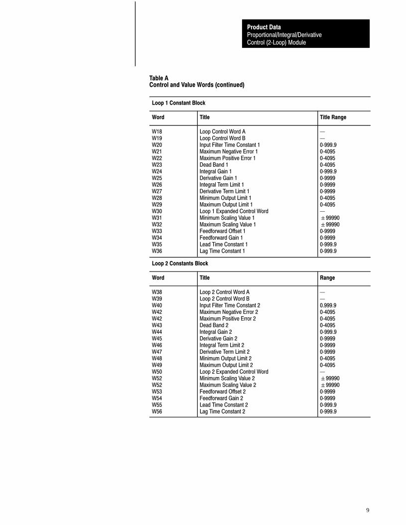
Table AControl and Value Words (continued)
Loop 1 Constant Block
Word Title Title Range
W18W19W20W21W22W23W24W25W26W27W28W29W30W31W32W33W34W35W36
Loop Control Word ALoop Control Word BInput Filter Time Constant 1Maximum Negative Error 1Maximum Positive Error 1Dead Band 1Integral Gain 1Derivative Gain 1Integral Term Limit 1Derivative Term Limit 1Minimum Output Limit 1Maximum Output Limit 1Loop 1 Expanded Control WordMinimum Scaling Value 1Maximum Scaling Value 1Feedforward Offset 1Feedforward Gain 1Lead Time Constant 1Lag Time Constant 1
0�999.90�40950�40950�40950�999.90�99990�99990�99990�40950�4095�99990�999900�99990�99990�999.90�999.9
Loop 2 Constants Block
Word Title Range
W38W39W40W42W42W43W44W45W46W47W48W49W50W52W52W53W54W55W56
Loop 2 Control Word ALoop 2 Control Word BInput Filter Time Constant 2Maximum Negative Error 2Maximum Positive Error 2Dead Band 2Integral Gain 2Derivative Gain 2Integral Term Limit 2Derivative Term Limit 2Minimum Output Limit 2Maximum Output Limit 2Loop 2 Expanded Control WordMinimum Scaling Value 2Maximum Scaling Value 2Feedforward Offset 2Feedforward Gain 2Lead Time Constant 2Lag Time Constant 2
0.999.90�40950�40950�40950�999.90�99990�99990�99990�40950�4095�99990�999900�99990�99990�999.90�999.9
Proportional/Integral/DerivativeControl (2�Loop) Module
Product Data
10
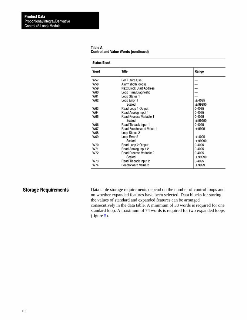
Table AControl and Value Words (continued)
Status Block
Word Title Range
W57W58W59W60W61W62
W63W64W65
W66W67W68W69
W70W71W72
W73W74
For Future UseAlarm (both loops)Next Block Start AddressLoop Time/DiagnosticLoop Status 1Loop Error 1
ScaledRead Loop 1 OutputRead Analog Input 1Read Process Variable 1
ScaledRead Tieback Input 1Read Feedforward Value 1Loop Status 2Loop Error 2
ScaledRead Loop 2 OutputRead Analog Input 2Read Process Variable 2
ScaledRead Tieback Input 2Feedforward Value 2
�4095�999900�40950�40950�4095�999900�4095�9999�4095�999900�40950�40950�4095�999900�4095�9999
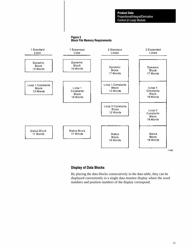
Data table storage requirements depend on the number of control loops andon whether expanded features have been selected. Data blocks for storingthe values of standard and expanded features can be arrangedconsecutively in the data table. A minimum of 33 words is required for onestandard loop. A maximum of 74 words is required for two expanded loops(figure 5).
Storage Requirements
Proportional/Integral/DerivativeControl (2�Loop) Module
Product Data
11
Figure 5Block File Memory Requirements
Display of Data Blocks
By placing the data blocks consecutively in the data table, they can bedisplayed conveniently in a single data monitor display where the wordnumbers and position numbers of the display correspond.
Proportional/Integral/DerivativeControl (2�Loop) Module
Product Data
12
Programming Considerations
The PID module has considerable programming versatility. A load/entersequence is used to configure the module with selected features, start PIDcontrol, or to change loop constants. Data can be transferred to the moduleand stored indefinitely in buffer memory until activated by a program logiccommand.
Bidirectional block transfers can be used for continuous communicationbetween PID module and PC processor. The PC processor reads the statusblock, then writes the dynamic block to the module in the next I/O scan.Continuous bidirectional block transfer is useful for adaptive control wherethe PC processor adjusts loop values based on data received by monitoringthe process.
The PID module is capable of operating independently without continuousblock transfer communication with the PC processor. Once the module hasbeen initialized, the module’s general status can be monitored continuouslythrough the status monitor byte without block transfers. The status monitorbyte reports the module’s detection of a module hardware fault, loss ofinput, or loss of analog power.
The module detects internal hardware failures and loss of communicationwith the PC processor. The manner in which the module responds to adetected fault is user selectable.
Hardware Fault
Module response to a detected hardware fault can be selected with internalprogramming (jumper) plugs prior to installation (table B). In the event ofa hardware fault, programming plug selection causes the module torespond in one of the following ways:
sets the analog output to the minimum value (+4mA or +1V DC)
holds the analog output to the last value before the fault occurred
sets the analog output to the maximum value (+20mA or +5V DC)
Also, when the module detects a hardware fault it automatically transferscontrol of the loop(s) to an manual control station (if used). The output ofthe manual control station can be controlled manually and overrides themodule’s output.
Fault Response

Proportional/Integral/DerivativeControl (2�Loop) Module
Product Data
13
Loss of Voltage
Module response to a detected loss of +5V DC can be selected, as well.
sets analog output to minimum value (+4mA or +1V DC)
sets analog output to maximum value (+20mA or +5V DC)
Outputs go to minimum value if �15V DC is lost.
Table BProgramming Plug Positions
Function Choice Plug Position
Digital Boardhard fault output
source of +5V DC
hold max/min,hold last state
backplaneexternal
E2 LEFT for max/min,E2 RIGHT for last state
E10 IN for backplaneE10 OUT for external
Analog Boardhard fault output 1
2maximum, minimummaximum, minimum
E5 OUT for max, IN for min.E4 OUT for max, IN for min.
output range 12
I, VI, V
E3, E6, E8 as shown in figure 6E1, E2, E7 as shown in figure 6
input range 12
I, VI, V
E15 IN for I, OUT for VE14 IN for I, OUT for V
tieback input 12
I, VI, V
E11 IN for I, OUT for VE12 IN for I, OUT for V
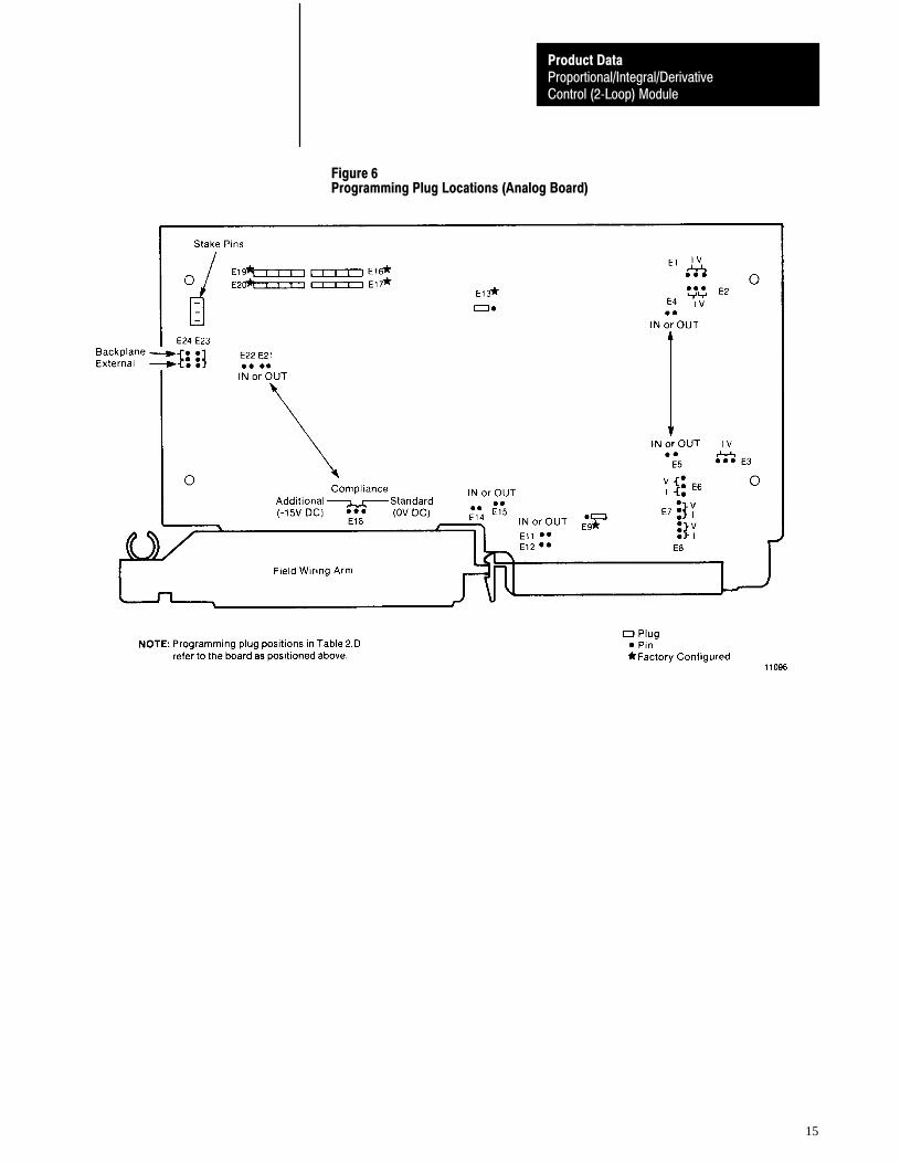
compliance standard, additional E18 as shown in figure 6E21, E22 IN for standard, OUTfor additional.
source of +5V DC back plane, external E23, E24 as shown in figure 6
Note: The current range I is +4 to +20mA, the voltage range is +1 to +5V DC.
Proportional/Integral/DerivativeControl (2�Loop) Module
Product Data
14
Communications Fault
The PID module detects the loss of communication with the PC processor(soft fault). Program logic enables the module to respond in one of thefollowing ways in response to a soft fault:
sets the analog output to the minimum value (+4mA or +1V DC)
holds the analog output to the last PID algorithm value before the softfault occurred
performs PID control based on the last values transferred to the PIDmodule before the soft fault occurred
sets the analog output to the maximum value (+20mA or +5V DC)
Switch position 1 on the last state switch assembly (I/O chassis backplane)must be set to the position for the soft fault response to operate. Note thatthis will cause the outputs of other modules in the same chassis to bede-energized when they detect a fault.
The response for each loop can be selected independently for a hardware orcommunications fault.
The PID module is a dual-slot module that occupies both slots of a modulegroup. The front panel contains three LED indicators and a write-on labelto record I/O ranges and the last date of calibration. Internally, the modulecontains a digital and an analog printed circuit board. The analog board islocated beneath the module cover containing the label that identifies theconnections to the field wiring arm.
Internal Selections
The PID module can accommodate a wide variety of applications. This ismade possible by positioning a number of programming plugs inside themodule. Selectable functions and corresponding programming plugs onboth circuit boards are listed in table B. Programming plug locations on theanalog circuit board are shown in figure 6.
Hardware
Proportional/Integral/DerivativeControl (2�Loop) Module
Product Data
15
Figure 6Programming Plug Locations (Analog Board)
Proportional/Integral/DerivativeControl (2�Loop) Module
Product Data
16
Indicators
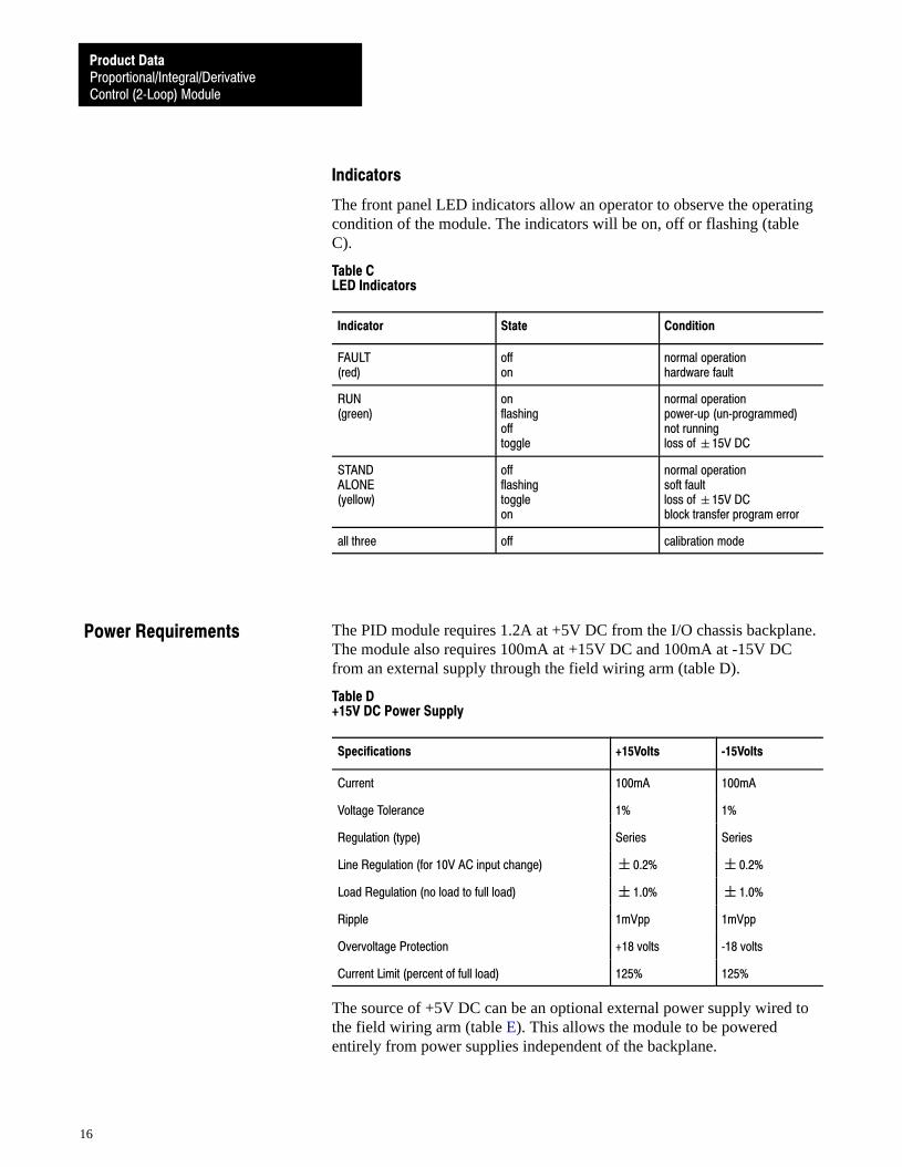
The front panel LED indicators allow an operator to observe the operatingcondition of the module. The indicators will be on, off or flashing (tableC).
Table CLED Indicators
Indicator State Condition
FAULT(red)
offon
normal operationhardware fault
RUN(green)
onflashingofftoggle
normal operationpower�up (un�programmed)not runningloss of �15V DC
STANDALONE(yellow)
offflashingtoggleon
normal operationsoft faultloss of �15V DCblock transfer program error
all three off calibration mode
The PID module requires 1.2A at +5V DC from the I/O chassis backplane.The module also requires 100mA at +15V DC and 100mA at -15V DCfrom an external supply through the field wiring arm (table D).
Table D+15V DC Power Supply
Specifications +15Volts �15Volts
Current 100mA 100mA
Voltage Tolerance 1% 1%
Regulation (type) Series Series
Line Regulation (for 10V AC input change) �0.2% �0.2%
Load Regulation (no load to full load) �1.0% �1.0%
Ripple 1mVpp 1mVpp
Overvoltage Protection +18 volts �18 volts
Current Limit (percent of full load) 125% 125%
The source of +5V DC can be an optional external power supply wired tothe field wiring arm (table E). This allows the module to be poweredentirely from power supplies independent of the backplane.
Power Requirements
Proportional/Integral/DerivativeControl (2�Loop) Module
Product Data
17
Table E+5V DC (Optional) Power Supply
Specifications +5V DC
Voltage (at field wiring arm) 5.05V DC
Current 1.2A
Voltage regulation (sum of all deviations due to line, load and ripple) �0.15V DC
Rise time (to 4.75V DC) 10ms
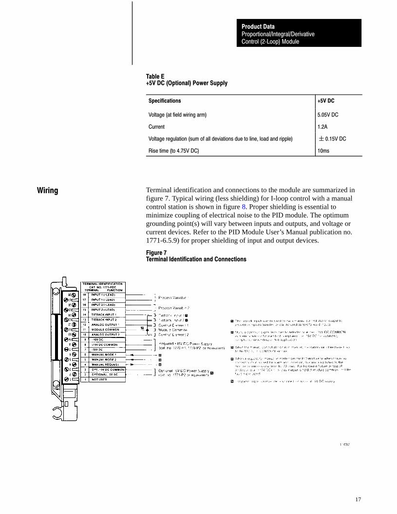
Terminal identification and connections to the module are summarized infigure 7. Typical wiring (less shielding) for I-loop control with a manualcontrol station is shown in figure 8. Proper shielding is essential tominimize coupling of electrical noise to the PID module. The optimumgrounding point(s) will vary between inputs and outputs, and voltage orcurrent devices. Refer to the PID Module User’s Manual publication no.1771-6.5.9) for proper shielding of input and output devices.
Figure 7Terminal Identification and Connections
Wiring
Proportional/Integral/DerivativeControl (2�Loop) Module
Product Data
18
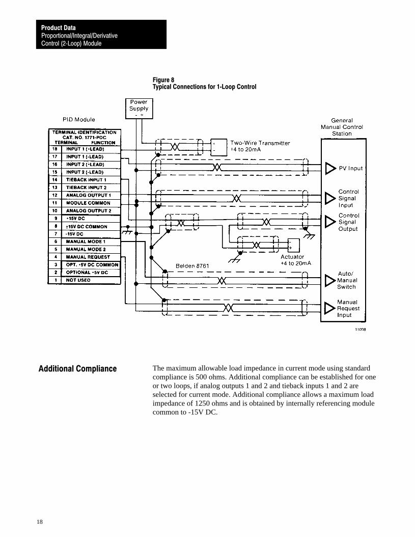
Figure 8Typical Connections for 1�Loop Control
The maximum allowable load impedance in current mode using standardcompliance is 500 ohms. Additional compliance can be established for oneor two loops, if analog outputs 1 and 2 and tieback inputs 1 and 2 areselected for current mode. Additional compliance allows a maximum loadimpedance of 1250 ohms and is obtained by internally referencing modulecommon to -15V DC.
Additional Compliance
Proportional/Integral/DerivativeControl (2�Loop) Module
Product Data
19
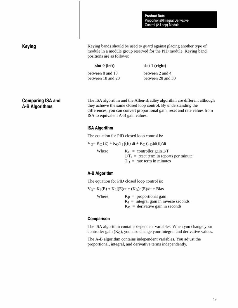
Keying bands should be used to guard against placing another type ofmodule in a module group reserved for the PID module. Keying bandpositions are as follows:
slot 0 (left) slot 1 (right)
between 8 and 10 between 2 and 4between 18 and 20 between 28 and 30
The ISA algorithm and the Allen-Bradley algorithm are different althoughthey achieve the same closed loop control. By understanding thedifferences, you can convert proportional gain, reset and rate values fromISA to equivalent A-B gain values.
ISA Algorithm
The equation for PID closed loop control is:
VO= KC (E) + KC/TI ∫(E) dt + KC (TD)d(E)/dt
Where KC = controller gain 1/T1/TI = reset term in repeats per minuteTD = rate term in minutes
A�B Algorithm
The equation for PID closed loop control is:
VO= KP(E) + KI ∫(E)dt + (KD)d(E)/dt + Bias
Where Kp = proportional gainKI = integral gain in inverse secondsKD = derivative gain in seconds
Comparison
The ISA algorithm contains dependent variables. When you change yourcontroller gain (KC), you also change your integral and derivative values.
The A-B algorithm contains independent variables. You adjust theproportional, integral, and derivative terms independently.
Keying
Comparing ISA andA�B Algorithms

Proportional/Integral/DerivativeControl (2�Loop) Module
Product Data
20
ISA Algorithm A�B Algorithm
Controller Gain KC(dimensionless)
Reset Term 1/TI(repeats per minute)
Rate Term TD(minutes)
Proportional Gain KP(dimensionless)
Integral Gain KI(inverse seconds)
Derivative Gain KD(seconds)
When using the A-B algorithm, you must convert the ISA controller gain,reset, and rate terms to gain values of the A-B algorithm.
Conversion
Convert ISA values to A-B values as follows:
KP = KC
KI = KP�I�TI)
60
KD = KP(TD)(60)
Example
If your desired ISA values are:
controller gain = KC = 1reset value = 1/TI = 5 repeats per minuterate term = TD = 3 minutes
convert them to A-B gain values as follows:
proportional gain = KP = KC = 1
integral gain = K1 =(1)(5)60
= 0.083
derivative gain = KD = (1)(3)(60) = 180
Selecting the Algorithm
You select the ISA or A-B algorithm by setting a bit in the control word.
Proportional/Integral/DerivativeControl (2�Loop) Module
Product Data
21
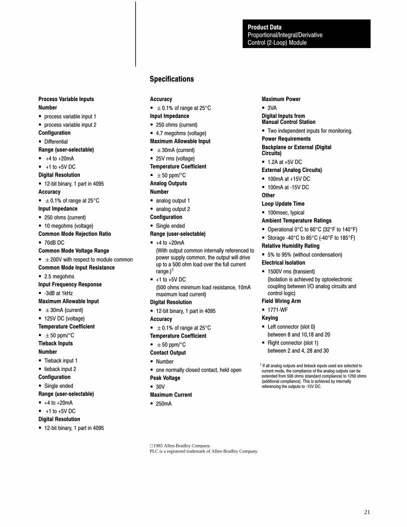
Specifications
Process Variable Inputs
Number
� process variable input 1
� process variable input 2
Configuration
� Differential
Range (user�selectable)
� +4 to +20mA
� +1 to +5V DC
Digital Resolution
� 12�bit binary, 1 part in 4095
Accuracy
� �0.1% of range at 25°C
Input Impedance
� 250 ohms (current)
� 10 megohms (voltage)
Common Mode Rejection Ratio
� 70dB DC
Common Mode Voltage Range
� �200V with respect to module common
Common Mode Input Resistance
� 2.5 megohms
Input Frequency Response
� �3dB at 1kHz
Maximum Allowable Input
� �30mA (current)
� 125V DC (voltage)
Temperature Coefficient
� �50 ppm/°C
Tieback Inputs
Number
� Tieback input 1
� tieback input 2
Configuration
� Single ended
Range (user�selectable)
� +4 to +20mA
� +1 to +5V DC
Digital Resolution
� 12�bit binary, 1 part in 4095
Accuracy
� �0.1% of range at 25°C
Input Impedance
� 250 ohms (current)
� 4.7 megohms (voltage)
Maximum Allowable Input
� �30mA (current)
� 25V rms (voltage)
Temperature Coefficient
� �50 ppm/°C
Analog Outputs
Number
� analog output 1
� analog output 2
Configuration
� Single ended
Range (user�selectable)
� +4 to +20mA
(With output common internally referenced topower supply common, the output will driveup to a 500 ohm load over the full currentrange.)1
� +1 to +5V DC
(500 ohms minimum load resistance, 10mAmaximum load current)
Digital Resolution
� 12�bit binary, 1 part in 4095
Accuracy
� �0.1% of range at 25°C
Temperature Coefficient
� �50 ppm/°C
Contact Output
� Number
� one normally closed contact, held open
Peak Voltage
� 30V
Maximum Current
� 250mA
Maximum Power
� 3VA
Digital Inputs fromManual Control Station
� Two independent inputs for monitoring.
Power Requirements
Backplane or External (DigitalCircuits)
� 1.2A at +5V DC
External (Analog Circuits)
� 100mA at +15V DC
� 100mA at �15V DC
Other
Loop Update Time
� 100msec, typical
Ambient Temperature Ratings
� Operational 0°C to 60°C (32°F to 140°F)
� Storage �40°C to 85°C (�40°F to 185°F)
Relative Humidity Rating
� 5% to 95% (without condensation)
Electrical Isolation
� 1500V rms (transient)
(Isolation is achieved by optoelectroniccoupling between I/O analog circuits andcontrol logic)
Field Wiring Arm
� 1771�WF
Keying
� Left connector (slot 0)
between 8 and 10,18 and 20
� Right connector (slot 1)
between 2 and 4, 28 and 30
1 If all analog outputs and tieback inputs used are selected tocurrent mode, the compliance of the analog outputs can beextended from 500 ohms (standard compliance) to 1250 ohms(additional compliance). This is achieved by internallyreferencing the outputs to �15V DC.
1985 Allen-Bradley Company.PLC is a registered trademark of Allen-Bradley Company.

Proportional/Integral/DerivativeControl (2�Loop) Module
Product Data
22
With offices in major cities worldwideWORLDHEADQUARTERSAllen-Bradley1201 South Second StreetMilwaukee, WI 53204 USATel: (1) 414 382-2000Telex: 43 11 016FAX: (1) 414 382-4444
EUROPE/MIDDLEEAST/AFRICAHEADQUARTERSAllen-Bradley Europe B.V.Amsterdamseweg 151422 AC UithoornThe NetherlandsTel: (31) 2975/43500Telex: (844) 18042FAX: (31) 2975/60222
ASIA/PACIFICHEADQUARTERSAllen-Bradley (Hong Kong)LimitedRoom 1006, Block B, SeaView Estate28 Watson RoadHong KongTel: (852) 887-4788Telex: (780) 64347FAX: (852) 510-9436
CANADAHEADQUARTERSAllen-Bradley CanadaLimited135 Dundas StreetCambridge, Ontario N1R5X1CanadaTel: (1) 519 623-1810FAX: (1) 519 623-8930
LATIN AMERICAHEADQUARTERSAllen-Bradley1201 South Second StreetMilwaukee, WI 53204 USATel: (1) 414 382-2000Telex: 43 11 016FAX: (1) 414 382-2400
As a subsidiary of Rockwell International, one of the world’s largest technologycompanies — Allen-Bradley meets today’s challenges of industrial automation with over85 years of practical plant-floor experience. More than 11,000 employees throughout theworld design, manufacture and apply a wide range of control and automation productsand supporting services to help our customers continuously improve quality, productivityand time to market. These products and services not only control individual machines butintegrate the manufacturing process, while providing access to vital plant floor data thatcan be used to support decision-making throughout the enterprise.
Publication 1771-2.34 — October, 1985Supersedes Publication 1771-948 — July, 1983
PN 955098-65Printed in USA
Top Related