


Languages
Pages
Legal


LTE Small Cell Selection
considering geo-located traffic, backhaul availability and street furniture

- 1 -
Executive summary
Planning a small cell network is far from a simple exercise. A robust methodology is required to
cost-effectively address capacity and throughput demands while keeping network interference
and costs in check.
There are many variables to be considered, but two key factors that will determine the best
approach are: site locations - are there pre-defined candidate site locations or is a “greenfield”
approach required? and traffic data: what type of information is available and at what
resolution?
The availability of street furniture databases (lamp posts, traffic lights etc.) is becoming more
popular. These provide fixed site locations, which somewhat limit design flexibility, but
significantly simplify and speed up site acquisition and the site build process.
Geo-located trace data is also becoming increasingly prevalent and is, at present, probably the
most commonly available traffic modelling option which provides sufficient accuracy for small cell
planning.
This paper looks at a small cell planning methodology where a street furniture database and
geo-located traffic data exists, a case which will be applicable to many operators looking to
deploy small cells. It proposes a 5 step process, using the most commonly available tools, for
operators to design the best possible LTE small cell network within budgetary and technical
constraints.

- 2 -
Introduction
With wireless data predicted to exceed wired data in the next few years and network capacity
demands to increase 10-15 fold over the next 5 years1, mobile operators are under pressure to
dramatically increase their network capacity and maintain data throughput rates, in a cost
effective manner.
To cope with the insatiable demand for data from customers and the difficulty of building
additional macro sites in dense urban environments, mobile network operators will look to small
cells to ensure their LTE networks have sufficient capacity and coverage to meet customer
demand.
This paper looks at a small cell planning methodology where a street furniture database and
geo-located traffic data exists, a case which will be applicable to many operators looking to
deploy small cells. It proposes a 5 step process, using the most commonly available tools, for
operators to design the best possible LTE small cell network within budgetary and technical
constraints.
The process consists of 5 key steps:
1. Traffic forecast
2. Candidate locations
3. Site ranking
4. Automatic site selection
5. Design verification
Traffic forecast
The first step in the design of a small cell network is to determine the capacity required and
more specifically where the traffic hotspots are. Due to the short inter site distance between
small cells it is critical to know the location of your traffic to a high degree of accuracy. Geo-
located traffic data, while not as accurate as desired (50m accuracy at best) is the preferred
option given its relative prevalence and ease of data acquisition. More accurate methods exist
but they are significantly more costly in terms of effort for a relatively small gain in accuracy.
Another challenge to overcome is the current status of the LTE macro network into which the
small cell network needs to be integrated. It is quite possible that the LTE macro network has
not yet launched or is newly launched with a very low penetration of users. In these cases it is
not feasible to use geo-located macrocell LTE traffic as a basis for a small cell network plan.
Our experience has shown that the best compromise is to use geo-located traffic from the
mature UMTS network as a solid starting point. This data then needs to be adapted to the
1 Cisco VNI 2012-2017 link to report

- 3 -
expected usage profile of an LTE user, while still respecting the traffic hotspot information from
the UMTS network. In 2012 an LTE connection generated 19 times more traffic than a non LTE
one but LTE penetration was less than 1%2 so this number is likely skewed by early adopters
and the heaviest users migrating first. An operator needs to consider all available forecast data
to improve the LTE traffic model to be used for dimensioning.
Depending on the planned usage of the LTE network it may also be necessary to consider voice
traffic (if a VoLTE strategy is planned).
Once the geo-located traffic forecast is obtained it can be used throughout the rest of the
process:
To visualise the traffic distribution in the map view of a radio planning tool.
To load the simulated network into the radio planning tool.
For RSRP & RSRQ array statistic reports in the radio planning tool.
For the weighting of RSRP & RSRQ targets in an ACP tool.
For the calculation of captured traffic in an ACP tool and the corresponding traffic
offloading due to captured traffic limits.
Candidate locations
For many LTE network deployments the first step will be to co-locate an LTE macro site with all
UMTS macro sites for areas where contiguous LTE coverage is required, such as city centres and
business districts. In many cases however, it is unlikely that this strategy will create good indoor
coverage with sufficient capacity, especially if the LTE frequency band is higher than the existing
UMTS one.
The screenshots below show the coverage and quality of a typical LTE macro cell layer in central
London. A similar scenario would likely be encountered in most city centres. The many indoor
locations with Reference Signal Received Power (RSRP) less than -110dBm and Reference Signal
Received Quality (RSRQ) less than -14dB highlight that the LTE macro network will not provide
the coverage or quality expected by customers.
2 Cisco VNI 2012-2017 link to report

- 4 -
Figure 1: LTE macro layer coverage (RSRP)
Figure 2: LTE macro layer quality (RSRQ)

- 5 -
Figure 3: LTE macro layer simulation reveals a large number of failures due to signal strength
and capacity
To create a network with sufficient coverage, quality and capacity, only a small cell layer will
provide a long term solution to the problem. It is expected that radio technologies like LTE
advanced and Wi-Fi offloading will help, but will not be sufficient and are either not readily
available or present bigger challenges than small cell deployments.
Loading a vector file of all available street furniture (i.e. traffic lights, lamp posts etc.) obtained
from the city planning department or other sources into a planning tool provides a list of
potential locations.
By configuring a site template in the radio planning tool with all the attributes of a typical small
cell, a nominal design can be quickly created. To maximise the candidate locations considered by
the ACP tool, a candidate small cell is placed at every possible street furniture location.
This nominal design is just the first step in the process - a starting point – and does not consider
specific clutter or capacity requirements. These aspects will be addressed in subsequent steps.

- 6 -
Site ranking
Backhaul is a much more critical consideration for small cell planning than it generally is for
macro cells. The two reasons for this are that backhaul makes up significantly more of the total
site costs in small cells, and with most small cell deployments happening in dense urban
surroundings backhaul planning is much trickier than it is for macro layers.
By performing LOS (Line-of-Sight) analysis between potential transmission hub and small cell
locations as well as small cell to small cell locations in a microwave planning tool, the best
available backhaul transmission option can be determined using a methodology similar to the
below. Backhaul links are selected from this list in descending order of preference:
For connections between to existing macrocell locations where LOS exists, point-to-point
microwave links are used.
If there is LOS to the point-to-multipoint LOS hub then point-to-multipoint LOS links are
preferred.
If there is limited LOS to one of the point-to-multipoint non-LOS hubs then point-to-
multipoint non-LOS links are preferred.
If there is LOS between two small cell locations then point-to-point E-band microwave
links are preferred.
If none of the above options are possible then fibre optic links are required.
To ensure an optimal design from a performance and cost point of view it is important to rank
all potential site locations according to the most cost effective backhaul which is feasible for that
site location. The options for backhaul to be considered in ascending order of total costs (CAPEX
and OPEX) are as follows:
Point-to-point microwave link
Point-to-point E-band microwave link
Point-to-multipoint LOS microwave links
Point-to-multipoint non-LOS microwave link
Fibre optic
Once the most feasible backhaul technology is determined for each site that site can be given a
weighting according to the cost (CAPEX and OPEX) of the transmission. This helps the ACP tool
determine the most optimal site locations by considering not only RF performance, but backhaul
feasibility and cost too.

- 7 -
Figure 4: Candidate site backhaul requirements
Automatic site selection
By considering the nominal site plan, the backhaul weighting factors, suitably scaled geo-located
traffic data and appropriate optimisation targets the ACP can optimise the design.
To obtain a high performance, yet cost effective design it is important to specify realistic
optimisation targets. Recommended targets should be in the region of -100dBm for RSRP and -
10dB for RSRQ. It is also recommended that the optimisation targets should be met in 95% of
the optimisation area while minimising costs to provide a good performance/cost trade-off.
Figure 5: Candidate site locations

- 8 -
Figure 6: Optimised network design
Design verification
Once the ACP completes the design optimisation, the final step is to transfer the new site
settings back into the radio and transmission planning tools and do a final design validation. This
could include small changes to fine tune the design which may be obvious to an engineer’s eye
but were not catered for in the targets and constraints when setting up the ACP. For example, if
a link meets the projected traffic growth with only a few per cent headroom it might be more
cost effective in the long run to install a slightly higher capacity link option and save additional
field work costs should actual traffic turn out to be marginally higher than forecast.
Figure 7: Coverage without (left) and with (right) the small cell network
- 9 -
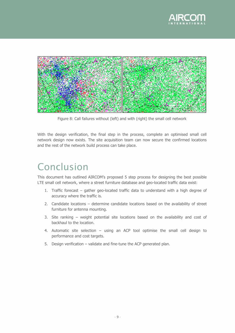
Figure 8: Call failures without (left) and with (right) the small cell network
With the design verification, the final step in the process, complete an optimised small cell
network design now exists. The site acquisition team can now secure the confirmed locations
and the rest of the network build process can take place.
Conclusion
This document has outlined AIRCOM’s proposed 5 step process for designing the best possible
LTE small cell network, where a street furniture database and geo-located traffic data exist:
1. Traffic forecast – gather geo-located traffic data to understand with a high degree of
accuracy where the traffic is.
2. Candidate locations – determine candidate locations based on the availability of street
furniture for antenna mounting.
3. Site ranking – weight potential site locations based on the availability and cost of
backhaul to the location.
4. Automatic site selection – using an ACP tool optimise the small cell design to
performance and cost targets.
5. Design verification – validate and fine-tune the ACP generated plan.

- 10 -
Products used
Successful planning of small cell networks requires a number of tools which work seamlessly
together. The following AIRCOM products play an integral role in the small cell planning
methodology proposed in this paper:
ASSET
ASSET is a multi-technology radio network design tool aimed at providing mobile network
planners with comprehensive and powerful capability in planning all the key mobile radio
networks. This includes the main radio design functions such as propagation modelling,
measurement data analysis, coverage analysis, traffic planning and static simulation as well as
more advanced processes including frequency planning and neighbour planning.
MYRIAD
Myriad is a universal propagation model. Following several years of research into propagation,
modelling, optimisation and algorithms, the MYRIAD propagation model is able to automatically
adapt itself to all cell types (micro, mini, small, and macro cells), environments (dense urban,
urban, suburban, mountainous, maritime, and open), and technologies (GSM, UMTS, LTE etc.) in
a frequency range from 200MHz to 5GHz.
For small cell planning the MYRIAD model is configured to utilise building vector data to provide
more realistic pathloss calculations in dense urban environments.
CONNECT
CONNECT is a microwave and backhaul transmission planning tool. It provides a complete
backhaul network planning solution covering microwave, optical, satellite and copper
technologies. It enables you to design and evaluate microwave networks across a variety of
architectures such as branch connections, multiple hops, loops or point to multi-point. It merges
powerful link engineering capabilities with a graphical map view to fulfil all microwave
transmission planning requirements.
Capesso™
Capesso is the market leading automatic cell planning tool. It combines data about the radio
network with planning objectives like coverage, capacity, quality and cost to automatically find
the best network design based on that information. Capesso is complementary to existing
planning and propagation software. It builds on investment in that software by automating the
multiple network processes for a faster more optimised design. Capesso is tightly integrated
with ASSET and delivers great value across the full spectrum of mobile radio standards and their
high performance extensions including GSM, UMTS and LTE.

About AIRCOM International
AIRCOM is an independent provider of network planning, optimisation and management
software and consultancy for mobile networks. Our products, all of which are now LTE capable,
enable operators to regain visibility and control of their network, which in turn drives efficiency
and profitability.
The market leader in the provision and deployment of network engineering tools, AIRCOM
products are in use across 155+ countries by over half the world’s mobile operators. Every day,
the 20 top global operators depend on AIRCOM’s tools and consultants to improve network
coverage and quality for more than 2 billion subscribers worldwide. Established in 1995, we
have built our reputation on creating and releasing additional value from within mobile networks.
As a provider of independent, multi-vendor, multi-technology consulting services, with over four
million hours working on 3G networks alone, our expertise translates into direct and measurable
cost savings for mobile operators. From initial advisory, through planning, optimisation and
operation, we are dedicated to maximising the performance of your network, and therefore your
business.
With offices in 14 countries, we provide regional viewpoints and resource, as well as ensuring
that our operator customers benefit from our global knowledge and expertise. By looking ahead
of the market, we develop the skills and tools, such as our small cell and SON offerings, that
network operators need to remain competitive.
WORLDWIDE HEADQUARTERS
AIRCOM International Ltd
TEL: +44 (0) 1932 442 000
EMAIL: [email protected]
AUSTRIA
TEL: +43 1 5855101-0
EMAIL: [email protected]
BELGIUM
TEL: +32 (0) 2704 92 00
EMAIL: [email protected]
BRAZIL
TEL: +55 12 3203 2199
EMAIL: [email protected]
CHINA
TEL: +86 21 6279 2779
EMAIL: [email protected]
INDIA
TEL: +91 124 451 7700
EMAIL: [email protected]
ITALY
TEL: +39 06 4542 2210
EMAIL: [email protected]
MEXICO
TEL: +52 (55) 5546 4633
EMAIL: [email protected]
PAKISTAN
TEL: +92 51 2272 184
EMAIL:
SINGAPORE
TEL: +65 6372 0548
EMAIL: [email protected]
SOUTH AFRICA
TEL: +27 11 745 1475
EMAIL: [email protected]
SWEDEN
TEL: +46 8 556 194 55
EMAIL: [email protected]
UAE
TEL: +971 4 391 2640
EMAIL: [email protected]
USA
TEL: +1 214 576 2700
EMAIL: [email protected]
www.aircominternational.com
Top Related