


Languages
Pages
Legal

1
Created March 4, 2005
Neil J. Gunther, M.Sc., Ph.D.Performance Dynamics Company
Afshar Explained
Updated June 5, 2005
2
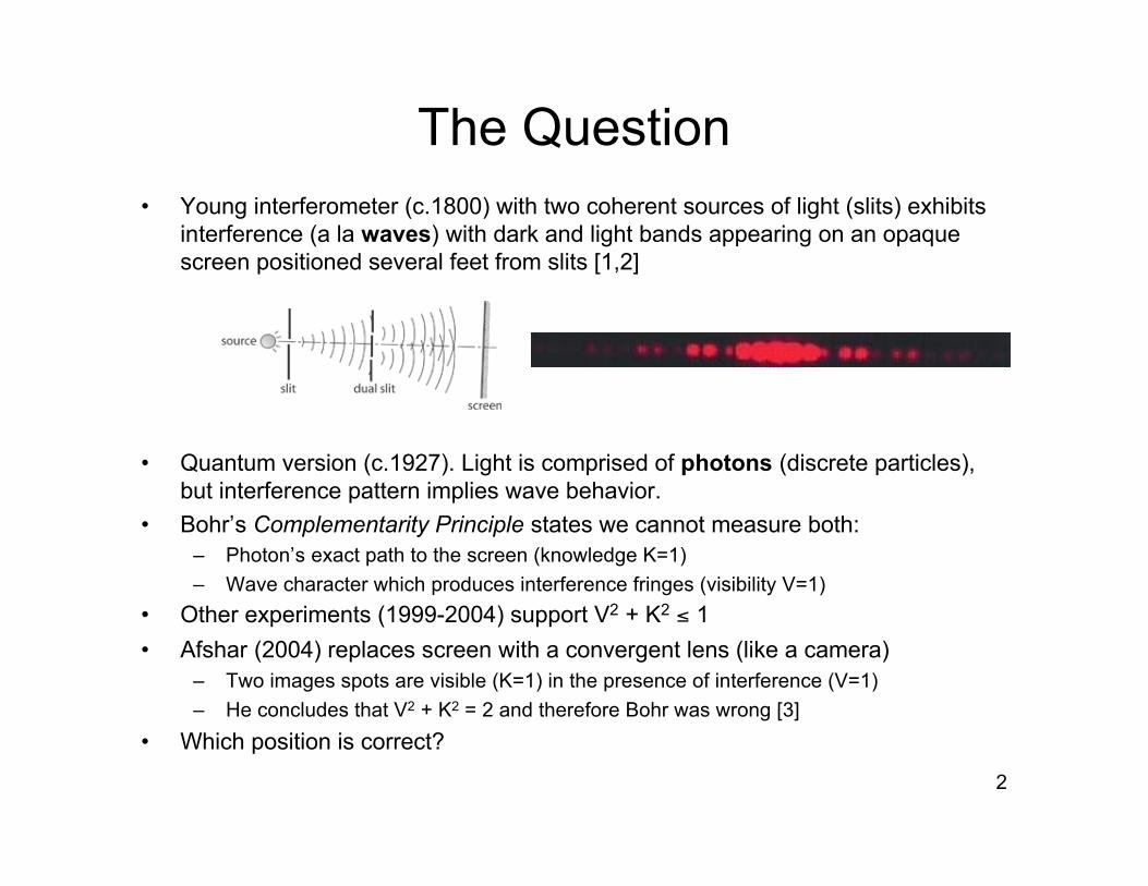
The Question• Young interferometer (c.1800) with two coherent sources of light (slits) exhibits
interference (a la waves) with dark and light bands appearing on an opaquescreen positioned several feet from slits [1,2]
• Quantum version (c.1927). Light is comprised of photons (discrete particles),but interference pattern implies wave behavior.
• Bohr’s Complementarity Principle states we cannot measure both:– Photon’s exact path to the screen (knowledge K=1)– Wave character which produces interference fringes (visibility V=1)
• Other experiments (1999-2004) support V2 + K2 ≤ 1• Afshar (2004) replaces screen with a convergent lens (like a camera)
– Two images spots are visible (K=1) in the presence of interference (V=1)– He concludes that V2 + K2 = 2 and therefore Bohr was wrong [3]
• Which position is correct?
3
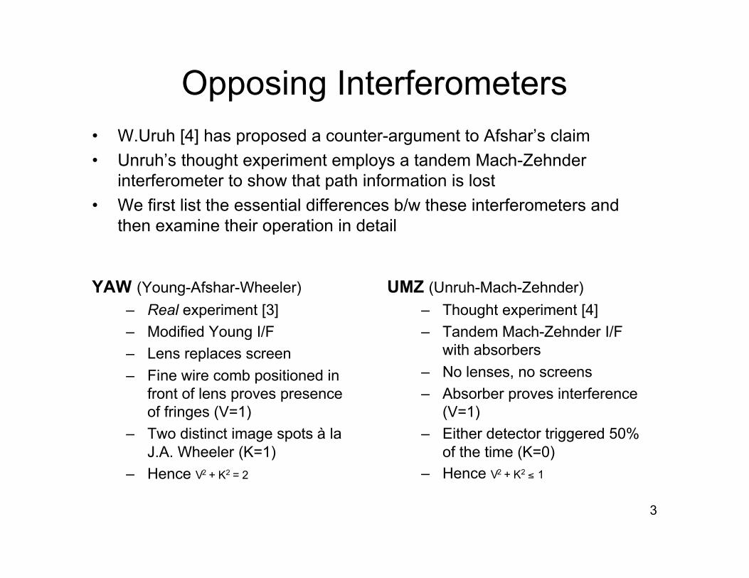
Opposing Interferometers
YAW (Young-Afshar-Wheeler)– Real experiment [3]– Modified Young I/F– Lens replaces screen– Fine wire comb positioned in
front of lens proves presenceof fringes (V=1)
– Two distinct image spots à laJ.A. Wheeler (K=1)
– Hence V2 + K2 = 2
UMZ (Unruh-Mach-Zehnder)– Thought experiment [4]– Tandem Mach-Zehnder I/F
with absorbers– No lenses, no screens– Absorber proves interference
(V=1)– Either detector triggered 50%
of the time (K=0)– Hence V2 + K2 ≤ 1
• W.Uruh [4] has proposed a counter-argument to Afshar’s claim• Unruh’s thought experiment employs a tandem Mach-Zehnder
interferometer to show that path information is lost• We first list the essential differences b/w these interferometers and
then examine their operation in detail

4
The YAW Interferometer
Imaging Photon Pathsin the Presence of Interference

5
Wheeler Interferometer
S1
OA
S2
Decide after photon leaves pinholes either to look ata pinhole with telescopes (K=1) or insert screen (V=1).
J. A. Wheeler, “Delayed Choice,” in Mathematical Foundations of Quantum Theory: Proceedingsof the New Orleans Conference on the Mathematical Foundations of Quantum Theory, edited by A. R. Marlow (Academic, New York, 1978)
6
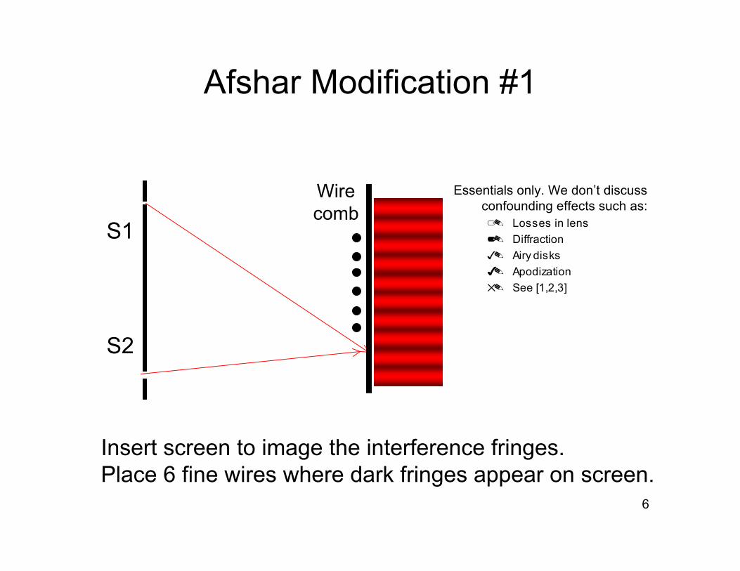
Afshar Modification #1
Insert screen to image the interference fringes.Place 6 fine wires where dark fringes appear on screen.
S1
S2
Wirecomb
Essentials only. We don’t discussconfounding effects such as: Losses in lens Diffraction Airy disks Apodization See [1,2,3]

7
Afshar Modification #2
Replace screen behind wires with a convergent lens.Replace Wheeler telescopes with photon detectors.
S1
S2
D1
D2

8
YAW Experiment: Step 1
Close one of the pinhole sources (e.g., S1).Single incoherent source (S2) means there is no interference.Wire comb scatters 6% of light flux if only S2 (or S1) is open.
S1
S2
D1
D2
9
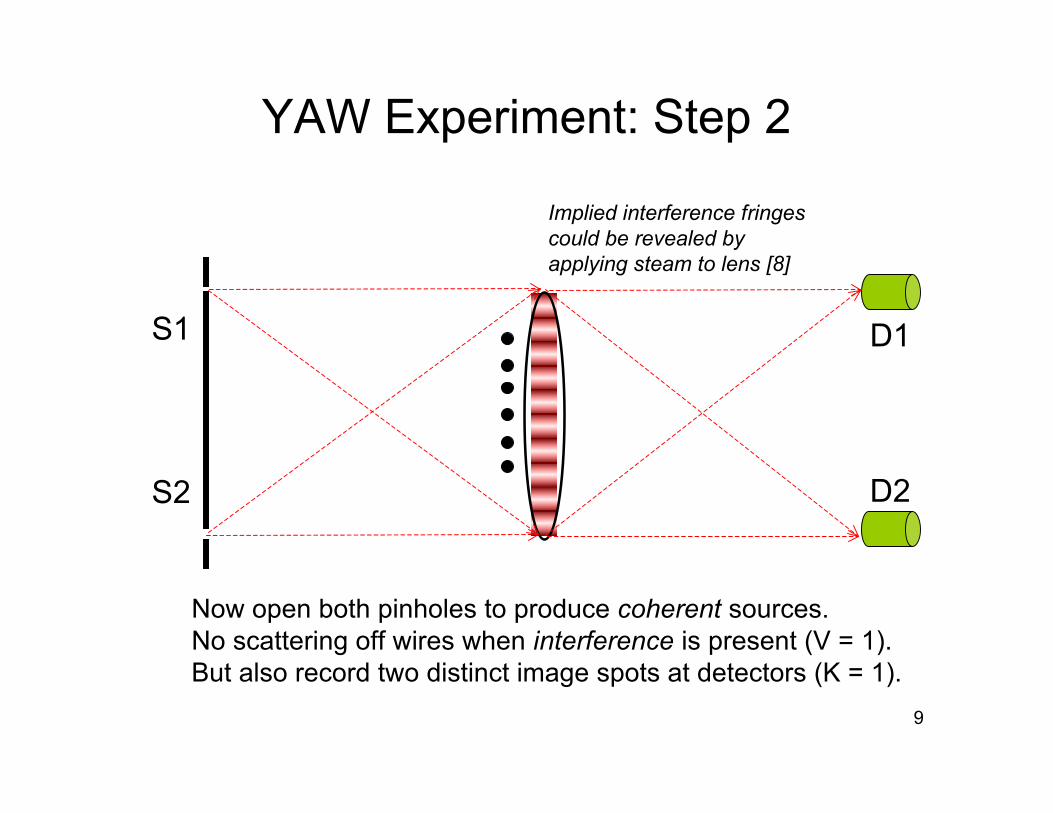
YAW Experiment: Step 2
Now open both pinholes to produce coherent sources.No scattering off wires when interference is present (V = 1).But also record two distinct image spots at detectors (K = 1).
D2
S1
S2
D1
Implied interference fringescould be revealed byapplying steam to lens [8]

10
The UMZ Interferometer
How Path Information Becomes Lostin the Presence of Interference
11
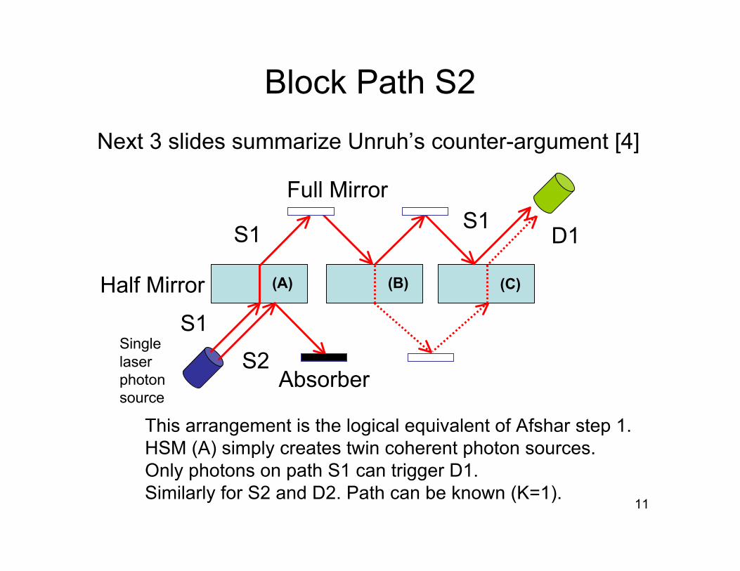
Block Path S2
This arrangement is the logical equivalent of Afshar step 1.HSM (A) simply creates twin coherent photon sources. Only photons on path S1 can trigger D1.Similarly for S2 and D2. Path can be known (K=1).
Absorber
Full Mirror
S1
S2
D1
Half Mirror
S1
S1
Singlelaserphotonsource
(A) (B) (C)
Next 3 slides summarize Unruh’s counter-argument [4]

12
Interfering Paths: Case 1
This arrangement is the logical equivalent of Afshar step 2.Mirror arrangement produces destructive interference in lowerchannel.Full mirror near (B) now replaced with an absorber (cf. Afshar wires).
Absorber
D1
D2
S1
S2
(A) (B) (C)
UMZ interferometer now adjusted to produce interference
13
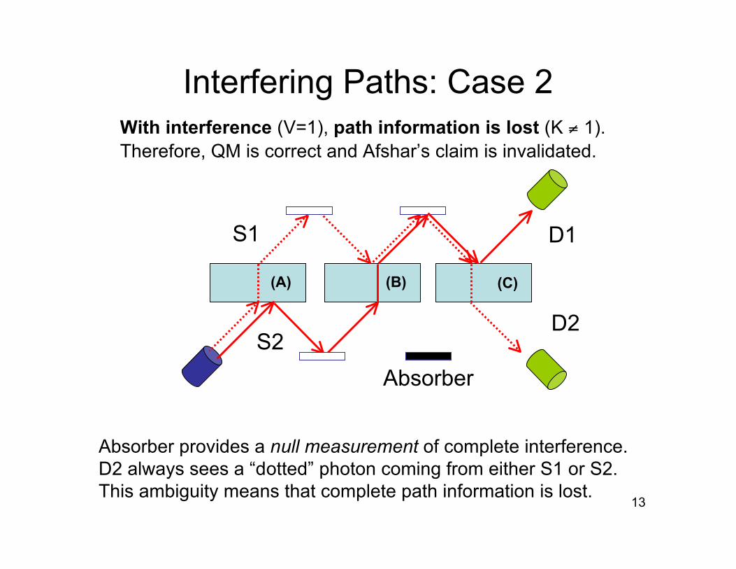
Interfering Paths: Case 2
Absorber provides a null measurement of complete interference.D2 always sees a “dotted” photon coming from either S1 or S2.This ambiguity means that complete path information is lost.
Absorber
D1
D2
S1
S2
(A) (B) (C)
With interference (V=1), path information is lost (K ≠ 1).Therefore, QM is correct and Afshar’s claim is invalidated.
14
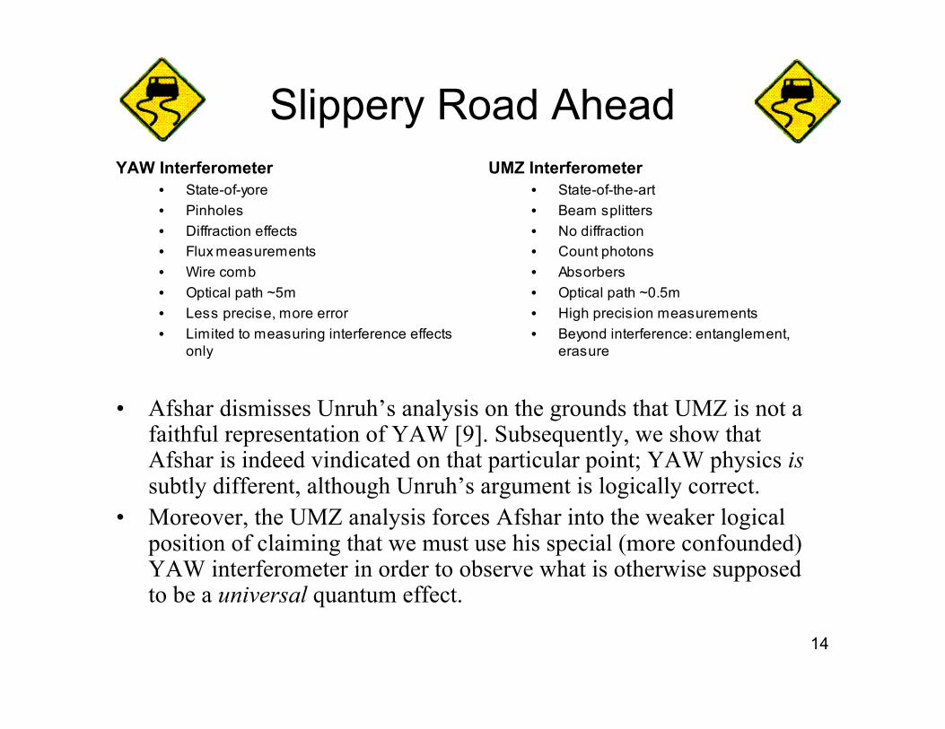
Slippery Road AheadYAW Interferometer
• State-of-yore• Pinholes• Diffraction effects• Flux measurements• Wire comb• Optical path ~5m• Less precise, more error• Limited to measuring interference effects
only
UMZ Interferometer• State-of-the-art• Beam splitters• No diffraction• Count photons• Absorbers• Optical path ~0.5m• High precision measurements• Beyond interference: entanglement,
erasure
• Afshar dismisses Unruh’s analysis on the grounds that UMZ is not afaithful representation of YAW [9]. Subsequently, we show thatAfshar is indeed vindicated on that particular point; YAW physics issubtly different, although Unruh’s argument is logically correct.
• Moreover, the UMZ analysis forces Afshar into the weaker logicalposition of claiming that we must use his special (more confounded)YAW interferometer in order to observe what is otherwise supposedto be a universal quantum effect.
15
Mapping Between YAW and UMZ
Why These Two InterferometersAre Not Identical

16
Simplified UMZ Schematic
S1
S2
D1
D2
Bright fringe
Dark fringe(no path)
HSM HSM
Only half-silvered mirrors (HSM) are shown.HSM (A) responsible for creating 2 sources elided.Full mirrors and absorber have also been elided.
(C)(B)

17
Equivalent UMZ Model of Lens
Dark fringe(no path)
S1
S2
D1
D2
Bright fringe
S1
S2
Posterior lens surfaceAnterior lens surface
But a real lens is not like UMZ. No HSMs or birefractive crystals. Single refractive index. Surfaces are not parallel.

18
The Paradox• Interference effects:
– Coherent UMZ sources => interference– Interference => xmit photon (bright) or not (dark)– Interference => must lose path information
• Refractive effects:– UMZ experiment uses bi-refractive HSMs
• Photon paths split 50/50, so path info is lost– YAW lens has a single refractive index
• So, Afshar claims path information is not lost

19
How Lenses Work
Bending Light Without Refraction
20
Index of Refraction
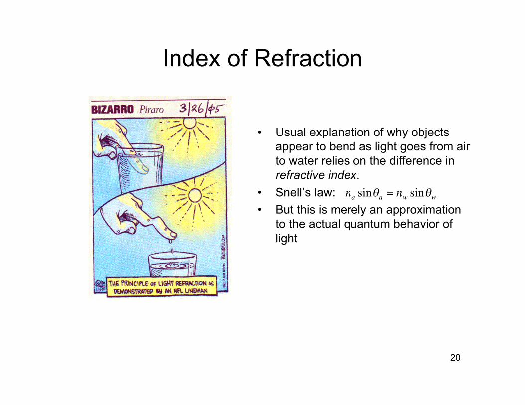
• Usual explanation of why objectsappear to bend as light goes from airto water relies on the difference inrefractive index.
• Snell’s law:• But this is merely an approximation
to the actual quantum behavior oflight
!
nasin"
a= n
wsin"
w
21
QPI Paths Through Free Space
a b
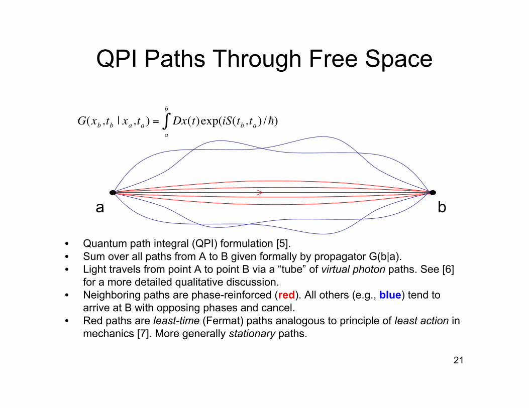
• Quantum path integral (QPI) formulation [5].• Sum over all paths from A to B given formally by propagator G(b|a).• Light travels from point A to point B via a “tube” of virtual photon paths. See [6]
for a more detailed qualitative discussion.• Neighboring paths are phase-reinforced (red). All others (e.g., blue) tend to
arrive at B with opposing phases and cancel.• Red paths are least-time (Fermat) paths analogous to principle of least action in
mechanics [7]. More generally stationary paths.
!
G(xb,tb| x
a,ta) = Dx(t)exp(iS(t
b,ta)
a
b
" /h)
22
QPI Paths Through a Lens
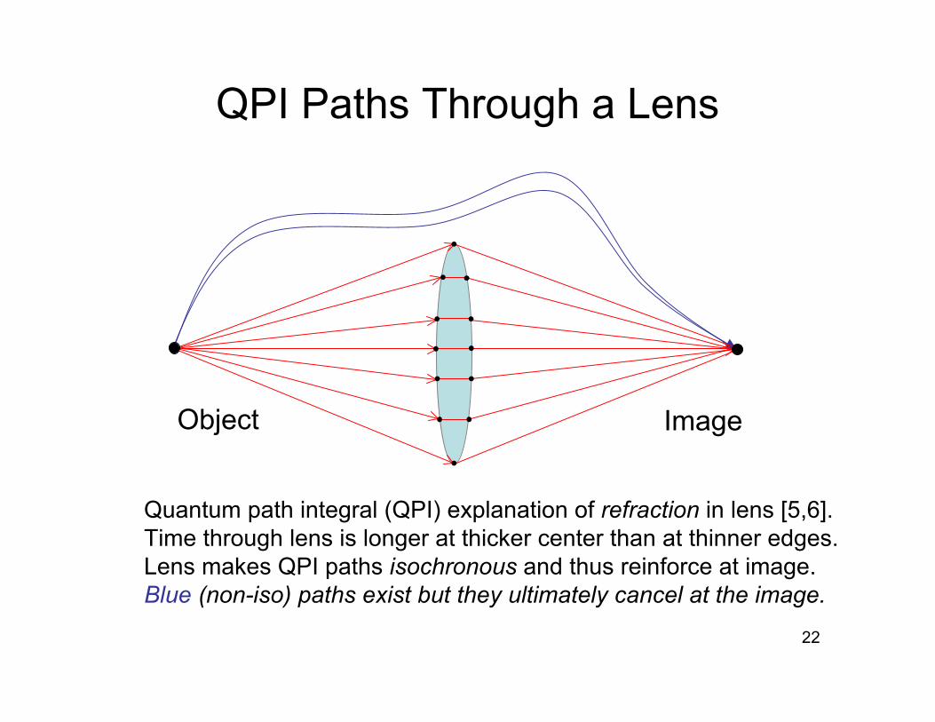
Quantum path integral (QPI) explanation of refraction in lens [5,6].Time through lens is longer at thicker center than at thinner edges.Lens makes QPI paths isochronous and thus reinforce at image.Blue (non-iso) paths exist but they ultimately cancel at the image.
Object Image

23
Off-Axis QPI Iso-Paths
Inverted image in convergent lens (red iso-paths).Non-iso blue paths exist, but cancel at image plane.
Object
Image
OA

24
Imaging Two Objects
Light is either scattered or emitted by each object.Sum over all virtual photon QPI paths.Surviving iso-paths produce two inverted images.
Obj1 Img2
OA
Obj2 Img1

25
Lens Refraction in Detail
A path S1 D1 takes less time than S1 D2.Any path S1 D2 takes the same time due tovarying thickness of lens (isochronous paths).
S1
S2
D1
D2Lens cross section
Inset

26
Paths S1–>D1 Cancel at D1
Neighboring BLUE path is slightly longer than red path.GREEN path is slightly shorter, so S1 D1 paths cancel. Similar cancellations occur for paths from S2 D2.
S1
S2
D1
D2Lens cross section
Inset

27
Refraction from Reinforcement
All S1 D2 paths take same time to reach D2.Phases of QPI paths reinforce each other at D2.
S1
S2
D1
D2Lens cross section
Inset
28
YAW Paradox Explained
How non-classical pathsS1 D1 and S2 D2
arise in a lens

29
Imaging Coherent Sources
Coherent sources => Interference is present like UMZ. But what happens beyond the lens at detectors D1, D2?
S1 D1
OA
S2 D2
?

30
• Preceding discussion about refraction in lenses resulting fromisochronous QPI paths is only true for incoherent light
• But YAW uses coherent light interference
• Interference is present independent of “seeing” fringes– Interference is the superposition of coherent QPI paths– Fringes correspond to a measurement viz, |sum QPI paths| 2– YAW wires or UMZ absorber constitute a null measurement
• Constructive interference produces BIFURCATION of photon paths– Maximally phase reinforced– Partially phase reinforced
• Maximally phase reinforced paths reach the image plane by simpletransmission (no refraction)
• Partially phase reinforced paths act like incoherent light and refract asdescribed previously
Phase Coherency

31
Bifurcation at Lens Center
Near OA, coherent QPI tubes are identical to isochronous paths.Surviving paths go from S1 D1, as well as from S1 D2.Same as 50/50 split in UMZ, but this only represents a partial contribution in the case of a lens.
S1
S2
D1
D2
OA
Inset
Lens cross sectionshowing implied phase coherency
32
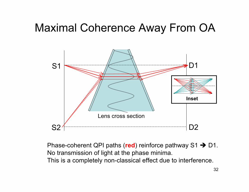
Maximal Coherence Away From OA
Phase-coherent QPI paths (red) reinforce pathway S1 D1.No transmission of light at the phase minima.This is a completely non-classical effect due to interference.
S1
S2
D1
D2Lens cross section
Inset

33
S1
S2
D1
D2Lens cross section
Inset
Bifurcation Away From OA
Maximally phase-coherent tube of paths from S1 D1.Partially phase-coherent tube of paths from S1 D2.All phase maxima result in similar bifurcations.

34
Bifurcation of QPI Paths• Non-classical QPI paths explain YAW paradox
– Afshar’s incorrect conclusion rests on a classical analysis of the opticsusing geometric ray approximation
• Twin incoherent light sources (e.g., light bulb, stars)– Paths S1->D1 cancel due to phase cancellations at detector D1– Only isochronous paths reinforce: S1 D2, and S2 D1
• Twin coherent light sources in YAW– Non-classical optical effects– Phase-coherent paths can bifurcate inside mono-refractive lens
• Bifurcation is a property of the light, not the lens• Physics of YAW is different from bi-refractive HSM in UMZ
– See two image spots due to symmetric transform from lens– The lens images the interference region (not the pinholes), therefore image
spots will also have a banded structure [8]
35
Some References1. M. Born & E. Wolf, Principles of Optics, Pergamon, 19702. R. Longhurst, Geometrical Optics, Longman, 19673. S. Afshar, “Sharp Complementary Wave and Particle Behaviors in the Same Welcher
Weg Experiment,” http://www.irims.org/quant-ph/030503/index.htm, preprint, Nov 20044. W. Unruh, “Shahriar Afshar–Quantum Rebel?”, http://axion.physics.ubc.ca/rebel.html, August
20045. R. Feynman & A. Hibbs, Quantum Mechanics and Path Integrals, McGraw-Hill, 19656. R. Feynman, QED: The Strange Theory of Light and Matter, Princeton, 19857. N. Gunther & T. Kalotas, “Comment on the Classical Limit of Feynman Path Integrals,”
AJP 45(10), 1000, 19778. G. Beretta, Private communication9. http://users.rowan.edu/~afshar/FAQ.htm
Top Related