


Languages
Pages
Legal


© Copyright 2008 Rockwell Collins, Inc. All rights reserved.
Proprietary InformationFor Training Purposes Onlly
AFDX – Real-time EthernetBy Mark Bobbin
O:\40-Teams\05-CS Architectures\cs-arch-engineering\administrative groups\schons-randy\AFDX Real-time Ethernet

2© Copyright 2008 Rockwell Collins, Inc. All rights reserved.
Proprietary InformationFor Training Purposes Only
Definition of a Real-time System [2]
• A real-time system is the combination of hardware and software elements interacting with their environment to produce functionally correct results before a specific deadline
• There are 3 classifications of real time systems based on their type of deadline:
– Hard real-time system can produce catastrophic consequences if it fails to meet its deadline
– The results of a firm real-time system cease to be useful as soon as the deadline expires, but the consequences of not meeting the deadline are not severe
– Soft real-time systems are real-time systems that are neither hard nor firm. The utility of results produced by a task with a soft deadline decrease over time after the deadline expires
Classifications of real-time systems

3© Copyright 2008 Rockwell Collins, Inc. All rights reserved.
Proprietary InformationFor Training Purposes Only
The Needs for AFDX
• Prior to AFDX systems were interconnected using dedicated cables that had a single origin and multiple destinations
• As system complexity increased the size and complexity of the interconnections grew quickly
• The complexity of systems increases the amount of information that must be exchanged
• A local area network technology had been used reduce the complexity of the cable plant and to increase the amount of information exchanged in industrial control applications
• To be widely adopted the network technology must be cheap, widely available, scalable, extensible, and opened to multiple vendors of network equipment
• To ensure interoperation of equipment interconnected by the network, the network protocol must support verification testing and validation of interoperation

4© Copyright 2008 Rockwell Collins, Inc. All rights reserved.
Proprietary InformationFor Training Purposes Only
Ethernet Began As a Shared Media
Z Z
Ethernet
Ethernet began as a shared bus protocol using CSMA/CD to access the shared bus.
It used the Binary Exponential Back-off algorithm to access the bus.
Poor performance when applied to heavily loaded networks
Indeterminate performance
• Transmit and listen for a collision• When a collision occurs wait a
random number• If another collision occurs wait
another random number• After 16 consecutive collisions give
up

5© Copyright 2008 Rockwell Collins, Inc. All rights reserved.
Proprietary InformationFor Training Purposes Only
Evolution From the Shared Media Began with the Hub
S D
Hub
• Physical connections were replaced with logical connections
• The hub became the collision domain
• Network is half-duplex

6© Copyright 2008 Rockwell Collins, Inc. All rights reserved.
Proprietary InformationFor Training Purposes Only
Switch Behavior
S D D S D
Switch
• Switches break up the network collision domains into each of the switch interfaces
• When multiple stations are transmitting simultaneously, frames can be delivered
• without collision[3]
• The switch is a full-duplex interconnection. There are no collisions using full duplex Ethernet

7© Copyright 2008 Rockwell Collins, Inc. All rights reserved.
Proprietary InformationFor Training Purposes Only
Fundamental Elements Within an Ethernet Switch[5]
Frames are forwarded
Frames are queued for
transmission
Frames Depart

8© Copyright 2008 Rockwell Collins, Inc. All rights reserved.
Proprietary InformationFor Training Purposes Only
Steps to Switch a Frame
1. Receive Frame2. Verify computed FCS and received FCS match3. Identify destination interface(s) by comparing Destination MAC
address to entries in forwarding table4. Enqueue Frame into destination interface(s) queues5. Transmit frame from switch
9© Copyright 2008 Rockwell Collins, Inc. All rights reserved.
Proprietary InformationFor Training Purposes Only
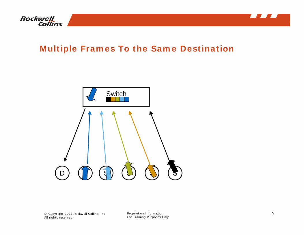
Multiple Frames To the Same Destination
D S S S S S
Switch

10© Copyright 2008 Rockwell Collins, Inc. All rights reserved.
Proprietary InformationFor Training Purposes Only
Frames Ready to Transmit From the Leftmost Switch Interface
• Frames are sent from the interface at the link speed (100 Mb/s)
• The queue is a finite depth, when to many frames arrive for a specific switch interface they are dropped
• The queuing delay through the switch contributes to the overall end-to-end delay

11© Copyright 2008 Rockwell Collins, Inc. All rights reserved.
Proprietary InformationFor Training Purposes Only
The Need for Admission Control
• In order to guarantee that all packets accepted in the system will arrive before their maximum delay, an admission control algorithm must be used to only accept tasks whose requirements can be satisfied

12© Copyright 2008 Rockwell Collins, Inc. All rights reserved.
Proprietary InformationFor Training Purposes Only
The Goals of AFDX
• Satisfying the customer needs for a common data bus and overcoming the problems of commercial switched Ethernet
• Provide high network availability• Permit logical interconnection using a network of end systems
and switches• Guarantee the maximum network delay and jitter will never be
exceeded• Permit creation of single producer, multiple consumers of
information with minimal network overhead• Permit interoperation with internet protocols• The AFDX network is an Ethernet network modified to the
environmental constraints of Aeronautical customers

13© Copyright 2008 Rockwell Collins, Inc. All rights reserved.
Proprietary InformationFor Training Purposes Only
AFDX End System and Switch

14© Copyright 2008 Rockwell Collins, Inc. All rights reserved.
Proprietary InformationFor Training Purposes Only
AFDX Switch
• Static routing through the switch• Path can go to one or many destination ports• Buffers exist at the output ports

15© Copyright 2008 Rockwell Collins, Inc. All rights reserved.
Proprietary InformationFor Training Purposes Only
Host-to-Host Connections
Host
Rate Regulation and Frame
Construction
IntegrityChecking
IntegrityCheckingR
edun
danc
y M
anag
emen
t
Timestamping and Frame
Decomposition
007
006
005
004
003
002
001 Host
Rate Regulation and Frame
Construction
IntegrityChecking
IntegrityChecking
Redundancy
Managem
ent
Timestamping and Frame
Decomposition
007
006
005
004
003
002
001
5
6
7
8
9
10
11
12
20
19
18
17
16
15
14
13
SWITCH
Store
Forward
Police4
3
2
1
21
22
23
24
5
6
7
8
9
10
11
12
20
19
18
17
16
15
14
13
SWITCH
Store
Forward
Police4
3
2
1
21
22
23
24

16© Copyright 2008 Rockwell Collins, Inc. All rights reserved.
Proprietary InformationFor Training Purposes Only
Ethernet Frame

17© Copyright 2008 Rockwell Collins, Inc. All rights reserved.
Proprietary InformationFor Training Purposes Only
AFDX Frame Principals
INCOMING FRAME
FORWARDING TABLE
Destination MAC Address Port
03-00-00-00-00-01 1603-00-00-00-00-0603-00-00-00-00-0B03-00-00-00-00-0C03-00-00-00-00-1003-00-00-00-00-13
12,13,147,8,9,10
1155
03-00-00-00-00-14 1,2,3,4,5
SFD Dest MAC Addrs=03:00:00:00:00:01
SRC MAC Addrs=02:00:00:04:8D:20 PAYLOAD FCSL/T

18© Copyright 2008 Rockwell Collins, Inc. All rights reserved.
Proprietary InformationFor Training Purposes Only
Virtual Link Principals
End System CEnd System BEnd System A
Virtual Link
Sub VL Queue
Network
ReceivePort
ReceivePort
Frame
Frame1
Frame2
Frame3
Frame4
BAG
• A single end system is the source of each VL.
• The bandwidth allocated to an individual VL is isolated from all other VLs
• Frames can be sent periodically using the BAG as a period.
• Frames can be sent sporadically using BAG as a minimum inter emission time

19© Copyright 2008 Rockwell Collins, Inc. All rights reserved.
Proprietary InformationFor Training Purposes Only
Enforcing BAG Makes the Network Deterministic
FaultedEnd
System
SwitchPolicer
1
2
3
4
5 16
17
18
19
20
Policer
Policer
BAG Regulator
BAG Regulator
BAG Regulator
BAG Regulator
BAG Regulator
End System
End System
End System
Policer

20© Copyright 2008 Rockwell Collins, Inc. All rights reserved.
Proprietary InformationFor Training Purposes Only
Ports Connect Host to Network
PCIBUS
HOSTPROCESSOR
Application
End System
Write
Rate Regulationand Frame
Construction
IntegrityChecking
IntegrityCheckingR
edun
danc
yM
anag
emen
t
Timestampingand Frame
Decomposition
Receive Ports
003
002
001
003
002
001
002
001
003
002
001
002
001
001
002
002
001
004
007
006
005
001
002
001
007
006
005
004
003
002
001
TransmitPorts
BAG Reg
Read

21© Copyright 2008 Rockwell Collins, Inc. All rights reserved.
Proprietary InformationFor Training Purposes Only
Transmit Path Association
V L B A G R e g u l a t o r
s u b V LQ u e u e
P o r t 1 P o r t 2 P o r t 3 P o r t 4
F r o m H o s t

22© Copyright 2008 Rockwell Collins, Inc. All rights reserved.
Proprietary InformationFor Training Purposes Only
Types of Transmit Ports
• The network addressing is statically configured for the AFDX port
• When using a SAP port the application program using the port can specify the destination UDP and IP addresses

23© Copyright 2008 Rockwell Collins, Inc. All rights reserved.
Proprietary InformationFor Training Purposes Only
Transmit Ports Connected to the Same SubVLShare the SubVL Queue
TxPort
TxPort
007006005004003002001
subVL
Tx VL
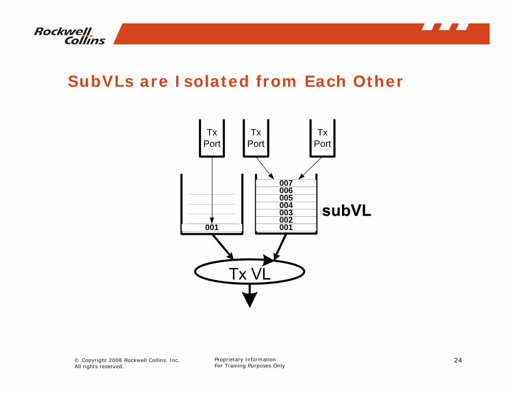
• When 2 or more ports share a subVL, they both have equal opportunity to use all of the resources in the subVL
24© Copyright 2008 Rockwell Collins, Inc. All rights reserved.
Proprietary InformationFor Training Purposes Only
SubVLs are Isolated from Each Other
TxPort
TxPort
007006005004003002001001
TxPort

25© Copyright 2008 Rockwell Collins, Inc. All rights reserved.
Proprietary InformationFor Training Purposes Only
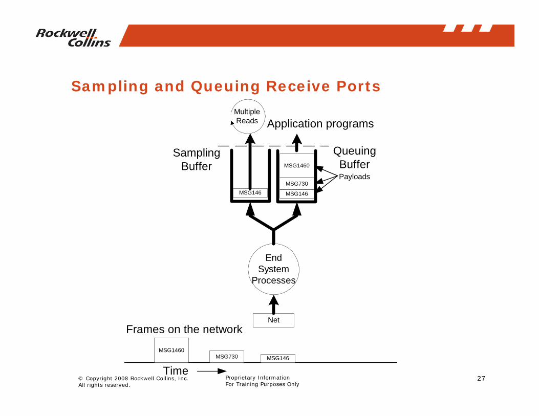
Receive Ports
• Associated with a single virtual link without a subVL• Multiple receive ports per virtual link• Destination port number in the End System is determined
using:– Destination MAC address (e.g. 03-00-00-00-11-01)
– Destination IP address (e.g. 10.14.222.30)
– Destination UDP port (e.g. 50025)

26© Copyright 2008 Rockwell Collins, Inc. All rights reserved.
Proprietary InformationFor Training Purposes Only
AFDX Receive
FCSRSNFRAME
FCSRSNFRAME
Integrity and Redundancy
Dst.MAC
Src.MAC L/T PAYLOAD
MAC
FCSRSN
LenVer TOS Len ID Flg. TTL Prot. Hd.Csum Src. IP Dst. IP PAYLOAD
IP
Src.UDP
Dst.UDP UDP Ln Csum PAYLOAD
UDP
PORT
PACKET
DATAGRAM
MESSAGE
27© Copyright 2008 Rockwell Collins, Inc. All rights reserved.
Proprietary InformationFor Training Purposes Only
Sampling and Queuing Receive Ports
MSG1460
MSG730
MSG146
EndSystem
Processes
Net
MSG1460MSG730 MSG146
Time
Frames on the network
Application programs
QueuingBufferPayloads
SamplingBuffer
MSG146
MultipleReads
28© Copyright 2008 Rockwell Collins, Inc. All rights reserved.
Proprietary InformationFor Training Purposes Only
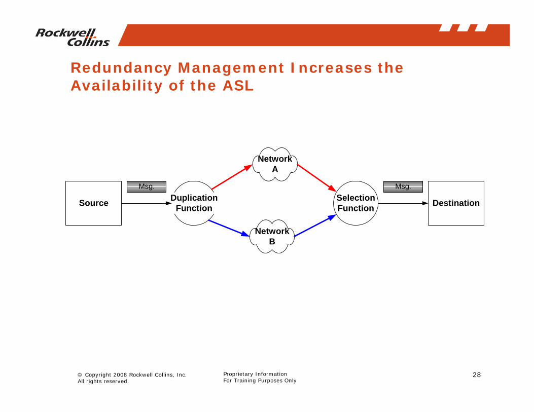
Redundancy Management Increases the Availability of the ASL
NetworkA
NetworkB
SelectionFunction
DuplicationFunction DestinationSource
Msg. Msg.

29© Copyright 2008 Rockwell Collins, Inc. All rights reserved.
Proprietary InformationFor Training Purposes Only
Receive Integrity Checking and Redundancy Management

30© Copyright 2008 Rockwell Collins, Inc. All rights reserved.
Proprietary InformationFor Training Purposes Only
Integrity Checking and Redundancy Management
End System ASIC
Rate Regulation andFrame Construction RED
Interface
BlueInterface
IntegrityChecking
IntegrityChecking
RedundancyManagement
Timestampingand Frame
Decomposition
PortTX
Port
RX
REDInterface
RSN08
RSN09
RSN0A
RSN0B
RSN0C
RSNFD
RSN0E
RSN10
RSN08
RSN09
RSN0B
RSN0C
RSN0D
RSN0E
RSN10
RSN08
RSN09
RSN0A
RSN0B
RSN0C
RSN0D
RSN0E
RSN10
BADCRC
FE 0FBLUE
Interface
FrameSelected
FrameLost
TimeOLD NEW

31© Copyright 2008 Rockwell Collins, Inc. All rights reserved.
Proprietary InformationFor Training Purposes Only
Host to Host Network
Host
Rate Regulation and Frame
Construction
IntegrityChecking
IntegrityCheckingR
edun
danc
y M
anag
emen
t
Timestamping and Frame
Decomposition
007
006
005
004
003
002
001 Host
Rate Regulation and Frame
Construction
IntegrityChecking
IntegrityChecking
Redundancy
Managem
ent
Timestamping and Frame
Decomposition
007
006
005
004
003
002
001
5
6
7
8
9
10
11
12
20
19
18
17
16
15
14
13
SWITCH
Store
Forward
Police4
3
2
1
21
22
23
24
5
6
7
8
9
10
11
12
20
19
18
17
16
15
14
13
SWITCH
Store
Forward
Police4
3
2
1
21
22
23
24

32© Copyright 2008 Rockwell Collins, Inc. All rights reserved.
Proprietary InformationFor Training Purposes Only
Conclusions
• Modifications to Ethernet make it suitable for avionics applications
• Data flows through an AFDX network on virtual links• The principal function of AFDX Switches is frame forwarding
and virtual link policing• End Systems interface to Hosts using transmit and receive
ports• AFDX is a redundant network that separates redundancy
management from host functions
33© Copyright 2008 Rockwell Collins, Inc. All rights reserved.
Proprietary InformationFor Training Purposes Only
References
1 – An Efficient RMS Admission control and its application to Multiprocessor Scheduling, S Lauzac, R Melhem, D. Mosse, 1063-7133/98
2 – Real-Time Computing: A New Discipline of Computer Science and Engineering, PROCEEDINGS OF THE IEEE, VOL. 82, NO. I , JANUARY 1994
3 – Worst Case Communication Delay of Real-Time Industrial Switched Ethernet With Multiple Levels, Kyung Chang Lee, Suk Lee, Man Hyung Lee. IEEE Transactions on Industrial Electronics, Vol 53, No. 5, October 2006.
4 - Communications for Integrated Modular Avionics, Rick Alena, J. Ossenfort, K. Laws, A. Goforth, F. Figueroa, IEEEAC Paper #1230
5 - Low-latency hard real-time communication over switched ethernet - Real-Time Systems, 2004. ECRTS 2004. Proceedings. 16th Euromicro Conference on Real-Time Systems
6 - Timelines of Real-Time IP Communication in Switched Industrial Ethernet Networks, Tor Skeie, Svein Johannessen, and Øyvind Holmeide, IEEE TRANSACTIONS ON INDUSTRIAL INFORMATICS, VOL. 2, NO. 1, FEBRUARY 2006
Top Related