


Languages
Pages
Legal


ATLASThe LTAO module for the E-ELT
Thierry FuscoONERA / DOTA
On behalf of the ATLAS consortium
Advanced Tomographywith Laser forAO systems

4
Advanced Tomographywith Laser forAO systemsThe ATLAS project
• “Advanced Tomography with Laser for Ao Systems”
• Institute : ONERA, GEPI, LESIA
• Duration : 16 months in 2 phases• Phase 1 : 7 months (already done)• Phase 2 : 9 months
• Associated scientific instruments• HARMONI,• METIS,• SIMPLE,
Other potential users• MICADO, OPTIMOS
ATLAS
LTAO

4
Advanced Tomographywith Laser forAO systemsGeneral Requirements for ATLAS
4m
1m
250mm
InstrumentM6
Geometry- ATLAS is a 4m diameter, 1m thickmodule.- Nasmyth focal plane is located insideATLAS
Mass- ATLAS maximum mass is 2.5 tons (1.5tons for the rotating structure plus 1Ton for the supporting structure)
focal plane
Field derotation provided by ATLAS rotation

4
Advanced Tomographywith Laser forAO systemsATLAS performance requirements

4
Advanced Tomographywith Laser forAO systemsATLAS Error budget
• Specification : 50 (70%) @ K => 290 (210) nm rms
• LGS : 260 nm rms (goal = 170 nm rms)
• high order correction through tomographic process
• NGS : 125 nm rms (2 mas rms for TT)
• Fast tip-tilt correction (telescope windshake + turbulence)
• Slow measurement of high order modes (« truth sensor »)

4
Advanced Tomographywith Laser forAO systemsLaser Guide Stars
error budget
2
NCPA
2
errorn calibratio
2
saturation DM
2
lin wfs
2
HF telescope
2
tismanisoplana 3Dspot
2
varstructure sodium
2
error model noise
2
error model
2
propag noise
2
y tomographlgs
2
chrom
2
ref diff
2
emp
2
aliasing
2
fit
2
res
2
!!!!!
!!!!
!!!!!!!!
+++++
++++
++++++=
nC
t
• Deformable optics: M4 and M5 already “defined” – no possible optimization
• LGS number and positions
• LGS WFS design
• Control: Tomographic reconstruction Temporal effects RTC design

4
Advanced Tomographywith Laser forAO systemsLGS configurations (number & positions)
Optimum Baseline
6 LGSBaseline ~ 4.3’
No LGS beam overlap NGS patrol FoV Ø = 2’
3D parameter space (number position flux)
Performance with 4 LGS << 5 LGS << 6 LGS
Small evolution with LGS FoV diameter
Patrol Fov Ø = 2 arcmin

4
Advanced Tomographywith Laser forAO systemsLGS : choice of a launching scheme
Fratricide effects
Launch behind M2
• Huge impact for some subapertures⇒ Rayleigh signal >> sodium one⇒ Useless sub-apertures⇒ Evolve with time (pupil rotation)
• Impact in nm rm ~ a few tens of nm rmsto be consolidated
• Contamination of scientific instruments (HARMONI)
8
Launch from M1 side
• No fratricide effects But :
Laser reconfiguration every TBC min/hours toavoid beam crosses
loop has to be open at these moments for TBCmin (to be consolidated)

4
Advanced Tomographywith Laser forAO systemsLGS : choice of a launching scheme
Spot elongation and noise propagation
• Spot elongation and noise propagation
E2E simulation . Telescope = 21m. Scaling factors 6 LGS position : 1 min ring Representative of 42 m
Tomographic performance M1 ≡ M2
Even a small gain from a pure performance point of view !
More uniform propagation onto modes !
9

4
Advanced Tomographywith Laser forAO systemsLGS WFS concept
• 3 concepts are studying• SH WFS (various config)• YAW• Pyramid
• choice of a baseline
LowLowHighSensitivity toRON
COSTCOSTNot yetDetectoravailability
BadBadGoodGain variations
GoodPoorGoodNoiseperformance
Pyr4Q
YAWSH12x12
Baseline for phase A : SH 12x12Options (still under study) : 4Q & YAW

4
Advanced Tomographywith Laser forAO systemsNumber of photons per sub-ap
• Assumption :SH-WFS 12x12 pixels
Noise propagationelongated < 2 x symmetric
Loop filtering=> attenuation factor of 1.5
Sampling frequency : 500 Hz•

4
Advanced Tomographywith Laser forAO systemsTomographic reconstruction
P = Turbulent layer altitudes & GS positionsM = WFS/DM model (IM)⇒direct model ⇒Critical parameters !
Turbulent layer strength⇒ Regularisation term ⇒ Less critical
WFS noise model ⇒ Regularisation term ⇒ Less critical

4
Advanced Tomographywith Laser forAO systemsTomographic reconstruction
Altitude evolutionper layer
Strength evolutionper layer
Initial Cn² profile
Accurate knowledge on layer position is required especially for highest layer ( > 5 km) knowledge @ ± 250 m or less
Cn² strength is less an issue
Need of : Good Cn² profiler & identification procedure More data & more analysis !

4
Advanced Tomographywith Laser forAO systemsLaser Guide Stars
error budget
2
NCPA
2
errorn calibratio
2
saturation DM
2
lin wfs
2
HF telescope
2
tismanisoplana 3Dspot
2
varstructure sodium
2
error model noise
2
error model
2
propag noise
2
y tomographlgs
2
chrom
2
ref diff
2
emp
2
aliasing
2
fit
2
res
2
!!!!!
!!!!
!!!!!!!!
+++++
++++
++++++=
nC
t

4
Advanced Tomographywith Laser forAO systemsRequirements and Strategy
PERTURBATION
REQUIREMENTS
Strong WindShake (WS): 280 mas rms
Turbulence : below WS/10 (in rms)
( )22222125 rmsnmothersanisonoisetempo !+++ """"
On Tip/Tilt/FocusInt
KALMAN
Low magnitude GSLow signal rejection
500Hz
STRATEGY
Control optimization : Kalman Filter @ 500Hz
Use of 2 NGS to perform tomography when there is nobright & close NGS
⇒Increase sky coverage
Optimization of the WFS spot size and energy
⇒ ADC (H & Ks bands)
⇒ Dedicated local DM
• use of LGS data
• open loop correction (a la MOAO)
4
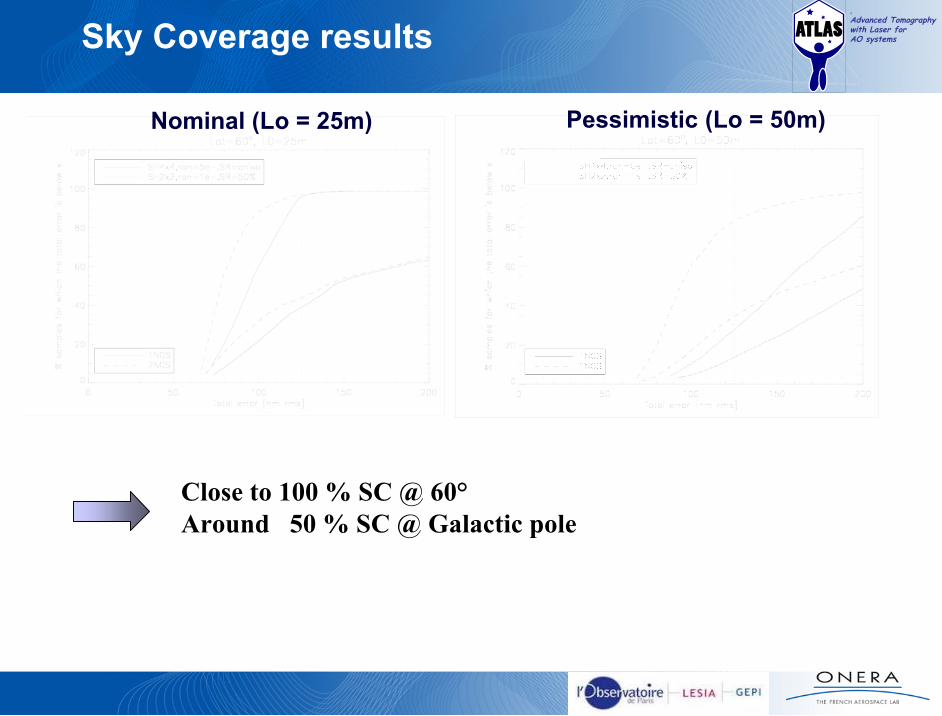
Advanced Tomographywith Laser forAO systemsSky Coverage results
Nominal (Lo = 25m) Pessimistic (Lo = 50m)
Close to 100 % SC @ 60° Around 50 % SC @ Galactic pole

4
Advanced Tomographywith Laser forAO systemsTrade-off / possible simplifications
• Main constraint : deal with the telescopewindshake
⇒ at least 500 Hz of sampling frequency• Turbulence only required 100 to 200 Hz
• If the telescope windshake is reduced at the level ofthe turbulence
⇒ no more need of µDM⇒ probably no more need of ADC⇒ EXTREME SIMPLIFICATION OF THE NGS DESIGN
⇒ HIGHLY DEPENDS ON THE OUTER SCALE !!!!!!!!!!!

4
Advanced Tomographywith Laser forAO systemsExpected Performance
Optimization area
Possibility to “play” with the performance optimisation area -> best performance on axis -> optimisation in a given FoV
It just requires a matrix modification in the RTC

4
Advanced Tomographywith Laser forAO systemsExpected Performance
Comparison with other AO systems
~ 50 %55 %LTAO
~ 50 %46 %(average perf. over 53”x53”)
MCAO
100 %< 1 %GLAO
<< 1 % (15” FoV)< 1 % (20” FoV) 1 % (30” FoV)
70 %55 %35 %
SCAO• Mag < 11• Mag < 12• Mag < 13.5
Sky Coverage@ Galactic pole
SR on axisAO systems

4
Advanced Tomographywith Laser forAO systemsATLAS performance : 100% SC
• Use of the “telescope” NGS for windshake estimation⇒ between 200 and 350 nm rms (assuming a 25 m outer scale and
a 0.71 arcsec seeing).⇒ This roughly leads to a final ATLAS performance in K band
(depending on the GS position from 5 -> 10 arcmin): SR = 0.6->0.5 %, FWHM = 15.5->16.9 mas, Jitter = 3.9->5.6 mas⇒ This value drops to SR = 0.4->0.2 %, FWHM = 20.9->33.1 mas, Jitter = 8.4->12.7 mas
• Use of 1 NGS magnitude 19 (in the patrol FoV [2’ Ø])⇒ 87 % SC @ galactic pole⇒ 98.3 % SC for the whole sky⇒ Can be used for WS correction
Between 4 mas and 12 mas rms for TTBetween 95 and 200 nm rms of defocus
SR : a few few tens of %

4
Advanced Tomographywith Laser forAO systemsATLAS design : summary
• 6 LGS in 4.2 arcmin Ø (launch from M1 side)• SH WFS• 84x84 sub-aperture• 12x12 pixels per sub-aperture• Sampling freq: 500 Hz
• LGS / NGS separation with mirrors only• Pupil stabilisation by ATLAS rotation• LGS fix w.r.t telescope referential
• 2 arcmin natural guide star FoV• Patrol foV : 30”2’ Ø• Scientific FoV : 30”1’ Ø
• 2 low order NGS WFS• 2x2 SH-WFS• Pixel size : 15 mas• 500 Hz (windshake correction)• IR band (H-Ks) with ADC• Internal DM for “MOAO-like” correction (using LGS tomographic data)
• 1 high order NGS WFS• 84x84 sub-apertures• From 500 Hz (SCAO case) 0.1 Hz (truth sensor)• VIS band (with ADC)
One LGS arm With VCM
PERF (K band on axis) : 55 %SC (in H-Ks) : 50 % @ galactic pole
Potential issue : Size of M6 !!!

4
Advanced Tomographywith Laser forAO systemsAtmospheric dispersion
Atmospheric Dispersion
0
500
1000
1500
2000
2500
450 650 850 1050 1250 1450 1650 1850 2050 2250 2450
Wavelength [nm]
Dis
pers
ion
[m
as]
Dispatm (15,700,0)
Dispatm (7.5,750,50)
Dispatm (0,800,100)
• 1600 – 1800 nm 30 mas (60°) / 10 mas (30°)• 1500 – 1800 nm 60 mas (60°) / 20 mas (30°)
Top Related