


![[Architecture eBook] Modern Bamboo Architecture](https://static.fdocuments.in/doc/165x107/55cf9acb550346d033a36e6f/architecture-ebook-modern-bamboo-architecture-562d0be9172fa.jpg)
Languages
Pages
Legal


Advanced Computer Architecture
Chapter 4:
More sophisticated CPU architectures
Lecturer: Paul H J Kelly
Autumn 2001
Department of Computing
Imperial College
Room 423
email: [email protected]
Cou
rse
web
site
: h
ttp://
ww
w.d
oc.ic
.ac.
uk/~
phjk
/Adv
ance
dCom
pute
rArc
hite
ctur
e.ht
ml
Advanced Computer Architecture Chapter 4 §0 1

CHAPTER 4
4.1 Control hazards, branch prediction
4.2 Pipelining With Multicycle Operations
4.3 Dynamic instruction scheduling:
scoreboarding
4.4 Register renaming: Tomasulo’s algorithm
4.5 Issuing multiple instructions per clock cycle
4.6 Speculative execution
Advanced Computer Architecture Chapter 4 §0 2

4.1 Control Hazards, Branch
Prediction
BEQZ R1,Label IF ID EX memWB
successor 1 IF stall stall IF ID EX memWB
successor 2 IF ID EX memWB
Cycle 1 2 3 4 5 6 7 8 9
A taken branch could cause a three-cycle delay
in the DLX pipeline - two stalls and a repeated
IF:
• Condition is tested in EX
• Branch target address is calculated during
mem stage (DLX branch is relative to PC)
((why??))
Even if the branch is not taken, we still suffer
one stall.
Branches are common - 10% – 20%
(H&P pp.161)
Advanced Computer Architecture Chapter 4 §1 3

• Two part solution:
– Determine branch taken or not sooner
– Compute taken branch address earlier
• DLX branch conditions are deliberately
simple: BEQZ, BNEZ
• DLX solution:
– Move zero test to ID stage
– Introduce dedicated adder in ID stage
for calculating branch target address
• One cycle stall
Advanced Computer Architecture Chapter 4 §1 4

How can we avoid this stall?
• Predict branch taken
Benchmark studies show 53% taken
Doesn’t really work in DLX - we don’t
know the destination address
• Predict branch not taken (47%)
– Don’t stall - execute next instruction
– But “squash” it if branch turns out to
be taken
– i.e. block memory access and WB
– Luckily these come late in pipeline in
DLX
Advanced Computer Architecture Chapter 4 §1 5

• Delayed branch
– Don’t stall - always execute next
instruction
– Don’t squash results
– Used in DLX, Sparc
• In DLX 5-stage pipeline, one delay slot is
enough to avoid branch delay.
• In more aggressively pipelined machine (eg
MIPS R4000) more delay slots would be
needed
Advanced Computer Architecture Chapter 4 §1 6

Where to get instructions to fill branch delay
slot?
• Before branch instruction
• From the target address (only useful if
branch taken)
• From fall-through (only useful if not taken)
• May need to add code to cancel effect of
delay slot instructions inadvertently
executed, eg at end of a loop
How well do compilers do?
• Fills about 60% of branch delay slots
• Of these, about 80% actually contribute
usefully
• Overall effectiveness: 60%×80% = 50%
• Effective average branch delay ≈ 50%
It is much harder to make effective use of
multiple delay slots
Advanced Computer Architecture Chapter 4 §1 7

“Cancelling” branches
Cancelling (or “nullifying”) branches are a
variation on delayed branches.
Idea:
• Get compiler to predict whether branch is
probably taken or not
• Have two variants of delayed branch -
– BEQZL “branch likely”: predicted
taken, ie delayed branch, cancel if not
taken
– BEQZU “branch unlikely”: predicted
not-taken, ie delayed branch, cancel if
taken
• Squash the delay slot’s updates if
mispredicted
Unfortunately, compilers are not very good at
predicting branches. Profile-based branch
prediction improves performance substantially.
Advanced Computer Architecture Chapter 4 §1 8

Branch delays in a deeper pipeline
Consider the MIPS R4000 pipeline structure:
• IF: first half of fetching of instrn; PC
selection happens here as well as initiation
of I-cache access
• IS: second half of I-cache access
• RF: instruction decode and register fetch
• EX: ALU operation - arithmetic, effective
address calculation, branch target
computation, condition evaluation
• DF: data fetch; first half of D-cache access
• DS: second half of D-cache access hit
• TC: tag check; determine whether the
D-cache access was a hit
• WB: write back for loads and
register-register operations
Advanced Computer Architecture Chapter 4 §1 9

Two cycle load delay:
LD R1,100(R2) IF IS RF EX DF DS TC WB
IF IS RF EX DF DS TC
IF IS RF EX DF DS
ADD R4,R1,R3 IF IS RF EX DF
Three cycle branch delay:
BEQZ R1,Label IF IS RF EX DF DS TC WB
IF IS RF EX DF DS TC
IF IS RF EX DF DS
IF IS RF EX DF
IF IS RF EX
Delayed branches are of little value here
Advanced Computer Architecture Chapter 4 §1 10

Run-time branch prediction
Using profiles to inform the compiler is
awkward and unsatisfactory ((why??))
Why not collect and use the information
dynamically?
(H&P pp.262)
Advanced Computer Architecture Chapter 4 §1 11

One-bit branch prediction
Idea: “Branch History Table”
• Maintain small table of branch predictions
• Indexed by low-order bits of PC
• Bit set indicates corresponding branch was
taken last time
Advanced Computer Architecture Chapter 4 §1 12

Performance of 1-bit prediction
Consider the conditional branch in a loop:
label:
body of loop
SUBI R1,R1,#1
BNEZ R1,label
• Suppose the loop is executed 9 times
• Branch is taken 9 times, not taken once
• What is the prediction accuracy, assuming
the prediction bit for the branch remains in
the prediction buffer?
Advanced Computer Architecture Chapter 4 §1 13

Q:
• Suppose the loop is executed 9 times
• Branch is taken 9 times, not taken once
• What is the prediction accuracy, assuming
the prediction bit for the branch remains in
the prediction buffer?
A:
• Will inevitably mispredict on 10th iteration
• Will also mispredict on first
• Because prediction bit was flipped on
previous execution of the loop’s last
iteration
– Branch is taken 90% of the time
– But correctly predicted only 80% of the
time
How can we do better?
Advanced Computer Architecture Chapter 4 §1 14

Two-bit branch prediction
Predict taken Predict taken
Predict not taken Predict not taken
not taken
taken
taken
not taken
not taken
not taken
taken
taken
Figure 1: State transition diagram for 2-bit
branch prediction
• Prediction misses twice before being
changed
• Need two bits for each table entry
• Implementation: either separate
cache-like BHT, or extra bits held with
each entry of the I-cache
• Still mispredicts 5% – 20%; many more
sophisticated schemes...
Advanced Computer Architecture Chapter 4 §1 15

Branch target prediction
• Predicting whether a branch is taken is not
much use in DLX because we have already
moved the test and target address
calculation into ID
• There is still a one-cycle branch delay
• The nullifying delayed branch idea uses
static prediction
• How can we avoid the delay when dynamic
prediction is correct?
• Problem:
BEQZ R1,Label IF ID EX memWB
successor 1 IF ID EX memWB
– Need to know the address from which to
load the next instruction
– Before the branch has been decoded!
Advanced Computer Architecture Chapter 4 §1 16

The Branch Target Buffer
Idea:
• Maintain small table
• Indexed by low-order bits of PC of
recently-executed branches
• Containing branch target address
• Accessed during IF, yields predicted next
PC
Advanced Computer Architecture Chapter 4 §1 17

Implementation:
• You must check that the prediction
actually refers to the current PC (cf tag
check in cache)
• BTB also includes branch prediction state
bits, and is updated when branch
prediction changes
• Must minimise cost of misprediction. E.g.
also fetch the predicted-not-taken
instruction
• Reduces branch delay to zero
– Can also predict virtual function calls
– Predicting function returns is harder;
see H&P pp.277
Advanced Computer Architecture Chapter 4 §1 18
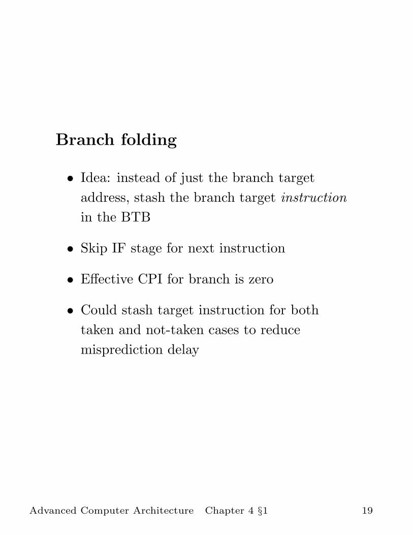
Branch folding
• Idea: instead of just the branch target
address, stash the branch target instruction
in the BTB
• Skip IF stage for next instruction
• Effective CPI for branch is zero
• Could stash target instruction for both
taken and not-taken cases to reduce
misprediction delay
Advanced Computer Architecture Chapter 4 §1 19

Control hazards: summary
• Branches are very common, often every 5
instructions or so
• Delayed branches rely on compile-time
instruction scheduling
• Cancelling delayed branches rely on static
branch prediction
• 1-bit, 2-bit and cleverer dynamic prediction
schemes
• 5% – 20% “hard core” of mispredicted
branches
• Branch Target Buffer reduces delay for
predicted branches to zero
• Misprediction delays must be minimised
• Large effective misprediction delay with
multiple issue and speculative execution
Advanced Computer Architecture Chapter 4 §1 20

4.2 Pipelining With Multicycle
Operations
• Up to now we have assumed that the EX
and MEM stages can always be finished in
one clock cycle.
• This may be difficult or impossible to
organise
• Examples:
– Integer multiply
– Integer divide
– Floating-point add, multiply
– FP divide, square root etc
? Cache misses
• How does this complicate pipeline control?
(H&P pp.187,201)
Advanced Computer Architecture Chapter 4 §2 21

FP arithmetic components
• FP arithmetic generally consists of several
stages. E.g. FP Addition (H&P pp.A-23)
– Unpack FP operands, deal with signs
– Shift so mantissae are aligned according
to exponents
– Add
– Renormalise, accommodating carries
– Round
– Compute sign of result
• Some are functionally distinct from one
another and are therefore efficient to
pipeline
• Some units are not easy to pipeline, leading
to structural hazards
• Some stages are used in more than one
instruction, leading to potential structural
hazards
Advanced Computer Architecture Chapter 4 §2 22

Example: R4000 FPU
Add: U S+A A+R R+S
Mul: U E+M M M M M N N+A R
Div: U A R D28 D+A D+R D+R D+A D+R A R
Cmp: U A R
cycle 1 2 3 4 5 6 7 8 9 10 11
Table shows FP stages needed by each FP instn
in each cycle:
U: Unpack FP numbers
S: Operand shift
A: Mantissa add
R: Rounding
E: Exception test
M:First stage of multiplier
N: Second stage of multiplier
D: Divide stage
Advanced Computer Architecture Chapter 4 §2 23

Supporting multiple outstandingFP operations
IF ID MEM WB
EX
M1 M2 M3 M4 M5 M6 M7 M8 M9
A1 A2 A3 A4
FP/integer divider
FP adder
FP multiplier
Integer unit
Figure 2: Multiple FP units, divide not
pipelined
Diagram shows fully-pipelined Add and
Multiply, but Divide is non-pipelined.
(H&P pp.190)
Advanced Computer Architecture Chapter 4 §2 24

Structural hazards
• In R4000 some stages are shared (eg
R,S,A) ⇒ structural hazards possible
• Non-pipelined stages (eg Divide)
• Initiation interval: The number of cycles
after initiation of an operation (eg Divide)
before another Divide can be issued
without structural stall
• Latency: the number of cycles after
initiation of an operation before the result
is available
Advanced Computer Architecture Chapter 4 §2 25

Example:
Suppose we have separate, non-pipelined FP
Add, Multiply and Divide units. Consider:
ADDF R3, R1, R2
SUBF R6, R4, R5
MULF R8, R6, R7
DIVF R10, R3, R9
Timing:
+ IF ID EX EX EX mem WB
− IF ID stall stall EX EX EX mem WB
× IF stall stall ID stall stall EX ...EX mem WB
÷ stall stall IF stall stall ID EX...EX mem WB
Figure 3: Structural and data stalls with non-
pipelined FPUs
Advanced Computer Architecture Chapter 4 §2 26

OBSERVE
• Because the DLX pipeline only issues
instructions in order, DIVF is stalled
unnecessarily
• Instructions are not necessarily completed
in order (“out-of-order completion”)
This creates new hazard possibilities.
Advanced Computer Architecture Chapter 4 §2 27

NEW DATA HAZARDS
Thus far we have seen one kind of data hazard:
a calculation must wait until a value it needs
has been calculated. There are actually three
kinds of data hazard:
RAW “Read after write”: the register must be
read after it has been written (or at least
calculated)
WAW “Write after write”: The register must be
written after previous instructions have
written to it - updates must be performed
in order
WAR “Write after read”: The register must only
be written to after previous instructions
have read it
WAW and WAR hazards couldn’t happen in
the simple DLX pipeline
(H&P pp.151)
Advanced Computer Architecture Chapter 4 §2 28

WAR
“Write after read”: The register must only be
written to after previous instructions read it:
DIVF R1, R2, R3 IF ID EX EX EX EX EX memWB
STORE R6, A IF ID stall stall stall EX memWB
SUBF R6, R4, R5 IF ID EX memWB
↑?R6 read here?
↑R6 written here
If R6 is only read when the STORE instrn is
ready to execute, it could already have been
overwritten by a later instruction.
WAR hazards cannot occur in DLX even
extended with long-latency FP operations:
• In DLX, registers are always read in order
in ID
• Copies of the operands are held when the
instruction is stalled
WAR hazards become a serious concern with
scoreboarding, as we see shortly.
Advanced Computer Architecture Chapter 4 §2 29

WAW
• EXAMPLE
With out-of-order completion, instructions
can write their results in a different order,
eg.
DIVF R1, R2, R3
STORE R1, A
SUBF R1, R4, R5
The divide finishes after the subtract,
leaving the wrong result in R1.
• This is called a WAW (Write-after-Write)
hazard.
• WAW hazards occur because instructions
no longer reach WB in order
Advanced Computer Architecture Chapter 4 §2 30

Handling WAW hazards
In our static DLX pipeline with multicycle
operations, we can neglect WAR hazards but
WAW hazards need attention.
A simple solution is to stall the WB stage so
that register writes occur in issue order.
This need not lead to a performance loss, if
enough forwarding is provided - but this can
get very complicated indeed.
Advanced Computer Architecture Chapter 4 §2 31

PERFORMANCE
Without out-of-order issue (covered in the next
section, this static-pipeline approach has
somewhat disappointing performance.
• EXAMPLE 1: Consider the spice
circuit-simulation benchmark (which
heavily involves floating point), running on
the MIPS R3000.
35% of total no of clock cycles are stalls:
load delays: 3% (assume perfect cache)
branch delays: 2%
FP structural stalls: 3%
FP data hazard stalls: 27%
• EXAMPLE 2: H&P pp.208 shows a
similar breakdown for R4000 - pipelining
the Add and Multiply doesn’t help
We will therefore focus on reducing data hazard
stalls; we will examine hardware techniques
first then consider compile-time approaches.
Advanced Computer Architecture Chapter 4 §2 32

4.3 Dynamic Instruction
Scheduling
IDEA: Allow instructions to issue out of order
when dependencies allow.
EXAMPLE:
DIVF R1, R2, R3
ADDF R4, R1, R5
SUBF R5, R5, R6
Here, ADDF is delayed waiting for result of
DIVF. Meanwhile SUBF can proceed. We must
delay writing it’s result, or take some other
action, or ADDF will get the wrong data.
• This is primarily of interest with
long-running operations such as FP
arithmetic and memory accesses
• Low-latency operations (such as integer
arithmetic) are handled separately by a
simple statically-scheduled pipeline
(H&P pp.241)
Advanced Computer Architecture Chapter 4 §3 33

Hazards
Goal: schedule execution to prevent hazards
from causing stalls. Recall the three kinds of
hazard:
• Control (conditional branches)
• Structural (contention for hardware)
• Data
– RAW (read-after-write)
– WAW (write-after-write)
– WAR - new
We will consider two approaches:
• Scoreboarding
Directly addresses RAW hazards
• Register renaming/Tomasulo
Overcomes WAW and WAR hazards
Register renaming is the basis for speculative
execution, which addresses control hazards.
Advanced Computer Architecture Chapter 4 §3 34

Instruction issue/overtaking
Fundamental principle:
• Split ID into two components:
– IS (Issue)
Each instruction is processed in order,
and the scoreboard is interrogated and
updated to reflect the data flow
– RO (read operands)
Buffer each issued instruction, wait
until no data hazards, then initiate
execution. Execution of delayed
instructions can start in any order
Simple assumption (for scoreboarding):
• Operands are always read from registers —
ie there is no forwarding
The role of the scoreboard is to activate those
appropriate instructions delayed in the RO
stage, just as soon as their operands are
delivered to their source registers.
Advanced Computer Architecture Chapter 4 §3 35

We modify the pipeline structure as follows :
IF IS
EX
M1 M2 M3 M4 M5 M6 M7 M8 M9
A1 A2 A3 A4
FP/integer divider
FP adder
FP multiplier
Integer unit
RO
RO
RO
RO
Registers
WB
WB
WB
WB
Figure 4: Data path for scoreboarding
Advanced Computer Architecture Chapter 4 §3 36

In more detail...
Issue: This stage processes instructions in
order.
It stalls if an instruction
• requires an FU which is busy
• shares its destination register with another
instruction already being executed.
When issue stalls, no further instructions can
be issued.
This deals with structural and WAW hazards.
Advanced Computer Architecture Chapter 4 §3 37

Read operands:
This stage maintains a table of instructions
received from the Issue stage. Each instruction
is delayed until its operands are available, that
is:
• an instruction can be executed as soon as
both its operands are available
• an operand is available if the register it’s in
is not currently being written, and will not
be written by any active instruction.
• When an instruction is activated, its
operands are fetched from the register file,
and the required FU is instructed to begin
execution
• This deals with RAW hazards.
Advanced Computer Architecture Chapter 4 §3 38

WB
• Essentially, when the FU completes, it
writes its result to the destination register.
• However, because of possible WAR
hazards, the scoreboard must be consulted
first. If a WAR hazard exists, the FU must
wait before writing its result.
• After updating the register, details are
relayed to the Read Operands stage so that
any instructions waiting are enabled.
Advanced Computer Architecture Chapter 4 §3 39

• Is it possible to perform dynamic
scheduling better?
• What might now cause a stall?
– Issue:
∗ structural hazard - inevitable
∗ WAW data hazard - rare but notice
that stall delays issue of other
instructions
– Read Operands:
∗ RAW data hazard - inevitable but
when data becomes available, it is
routed via a register, with extra cycle
delay.
If several instructions are waiting for
one value, they could all start as soon
as it becomes available - but have to
access registers serially.
– WB:
∗ WAR hazard
This is not inevitable
Advanced Computer Architecture Chapter 4 §3 40

The term scoreboard was introduced with the
first processor with dynamic instruction
scheduling, the CDC 6600, produced by
Control Data Corporation in 1964: this was the
first real “supercomputer”.
The 6600 had 16 Functional Units (FUs):
• 4 FP units, 7 integer units and 5 memory
units.
A revised design, the 7600 had one, pipelined
FP adder and one pipelined FP multiplier
instead of 4 non-pipelined units. The dynamic
instruction scheduling issues are the same.
Advanced Computer Architecture Chapter 4 §3 41

Scoreboard control
IF IS
EX
M1 M2 M3 M4 M5 M6 M7 M8 M9
A1 A2 A3 A4
FP/integer divider
FP adder
FP multiplier
Integer unit
RO
RO
RO
RO
Registers
WB
WB
WB
WB
• Reservation stations (RO) hold instns
which are executing or awaiting operands
• Instn is blocked in IS until reservation
station is free
• Broadcast destination register of
completing instn to enable instns waiting
for it
Advanced Computer Architecture Chapter 4 §3 42

• But check for WAR hazard first ((how))
Advanced Computer Architecture Chapter 4 §3 43

Costs of scoreboarding
• Need comparators to monitor completing
instructions’ destination registers, + WAW
and WAR hazard detection
• Multiple buses and perhaps also multiple
ports for register file
Advanced Computer Architecture Chapter 4 §3 44

4.4 Tomasulo’s “Register
Renaming” scheme
The scoreboarding scheme is somewhat
unsatisfactory because :
• It fails to perform forwarding - operands
cannot be used until they have been
written to the register file.
• WAR hazards still cause stalls
Tomasulo’s design deals with both these
problems in an interesting way.
(H&P pp.251)
Advanced Computer Architecture Chapter 4 §4 45

IDEA:
When a functional unit finishes an instruction,
broadcast the result on a common data bus, to
all the functional units, just in case this is what
they’re waiting for.
Q: How does an FU know what it’s waiting
for?
A: Each FU is fronted by a buffer, a
“reservation station”, containing the
opcode it is supposed to perform, and the
operands
– OR If the operand is not yet available,
the reservation station holds a tag
identifying the FU which will generate
the operand.
Advanced Computer Architecture Chapter 4 §4 46

• When an FU finishes an instruction, it
broadcasts (on the common data bus) the
result, together with a tag, its FU number.
• All the reservation stations monitor the
common data bus. Watching out for the
results whose tags match the operand tags.
• A reservation station activates its FU as
soon as
– the FU has finished it previous
instruction
– both operands have arrived.
Advanced Computer Architecture Chapter 4 §4 47

How is this done?
opcode operand1 operand2
Reservation Station 1 RS2 RS3
Functional Unit 1 FU2 FU3
Registers
R0
R1
R2
R3
R4
R5
R6
R7
Identifierof generating FU,if value is still being calculated
Value, if present
Common Data Bus (CDB)
=? Update reg if tag matches
=? Update reg if tag matches
Instruction Issue
Opcode
tag assignment/register renaming
• Each register monitors the CDB for a value
tagged appropriately and updates the its
contents when a match occurs
Advanced Computer Architecture Chapter 4 §4 48

THE SEQUENCE OF EVENTS
ISSUE
• Get an instruction from the floating-point
operation queue. If there is an empty
reservation station for an appropriate FU,
sent the opcode and destination register to
the reservation station.
• If the operands are in registers, send them
too.
• If an operand is not yet in a register, it
must be being computed by some active
FU. Send the identifier tag for the FU to
the reservation station instead.
(To do this, the registers are tagged with
the FU which will provide their value).
Advanced Computer Architecture Chapter 4 §4 49

EXECUTE
• If one or more of the operands is not yet
available, monitor the common data bus
until a value with the appropriate tag
appears.
• When both operands are available and the
FU is free, execute the operation.
• This ensures RAW hazards are dealt with.
WRITE RESULT
• When the FU finishes, broadcast it on the
common data bus, and from there in to the
registers and any FU’s waiting for this
result.
Advanced Computer Architecture Chapter 4 §4 50

STRUCTURAL HAZARDS
• The reservation stations form a buffer,
allowing an instruction to be issued to the
RS even if the FU is busy.
• The instruction will be stalled in the RS
until the FU is free
• If another instruction needs the FU, it will
stall in the issue stage until the RS is free.
This may cause delay in issuing other
instructions
• The CDB limits the machine to one
completion per clock. If several
instructions complete in the same cycle a
priority scheme is used to provide access to
the CDB serially.
Q: Is it possible to deal with this by
duplicating the CDB?
Advanced Computer Architecture Chapter 4 §4 51

WAR HAZARDS
EXAMPLE
MULF R0, R0, R2
SD R0, 0(R11) (Store R0)
MULF R0, R4, R6
SD R0, 8(R11) (Store R0)
• Note that there is no data dependence
between the MULF instructions, but there
is a WAR hazard (“anti-dependence”)
between the first SD and the second
MULF.
• With the scoreboard scheme this results in
a stall
• With Tomasulo’s scheme it does not.
WHY?
Advanced Computer Architecture Chapter 4 §4 52

WAW HAZARDS
EXAMPLE
MULF R0, R2, R4
ADDF R0, R6, R8
• When MULF is issued the register R0 will
be marked with the identifier of the
multiply unit.
• Ordinarily, any following instruction which
uses R0 would get its operand from the
multiply unit when it finishes, via the
CDB.
• However, when the ADDF is issued,
register R0 is marked with the identifier
tag of the adder.
• When the multiply completes, it will
broadcast on the CDB, but no register or
FU will be interested.
Advanced Computer Architecture Chapter 4 §4 53

Register renaming
• WAR hazards happen when a register is
reused
• This could be avoided by the compiler - if
instruction set has enough registers
• In a loop, can’t avoid reusing registers in
successive iterations (except by unrolling)
• Tomasulo’s scheme dynamically assigns a
tag to each value to be calculated
• You need a distinct tag for each reservation
station - so in effect, tags identify
additional registers in the machine,
invisible to the programmer
• The instruction-level parallelism is not
limited by the number of registers available
(Tomasulo was working on the IBM
360/91, which had to use an instruction set
with just 4 FP registers)
Advanced Computer Architecture Chapter 4 §4 54

Memory accesses
• We have not looked at how loads and stores
are handled. This is an important area
where dynamic scheduling is advantageous
• With dynamic scheduling, loads and stores
can be re-ordered
Advanced Computer Architecture Chapter 4 §4 55

Memory access disambiguation
To get loads right when loads and stores can be
reordered, we need to check the actual
addresses:
• Maintain a buffer containing the target
addresses of issued store instructions
• Check each load to see whether its target
address matches the address of an
outstanding store
• If so, stall the load until the value to be
stored becomes available, and substitute it
in — bypassing the memory.
Advanced Computer Architecture Chapter 4 §4 56

TOMASULO : CONCLUSIONS
• Yields improved performance through
→ reduced latency via forwarding
→ reduced stalls due to structural, WAR
and WAW hazards
• Substantial hardware cost
– Associative lookup needed for tag
matching
– For every register and reservation
station
– Tag matching must be very fast
• Performance could be improved by
duplicating the CDB, but would need to do
double tag matching at every register and
reservation station
Advanced Computer Architecture Chapter 4 §4 57

4.5 Multiple instructions/cycle
How can we reduce CPI to less than 1?
• “Superpipelined”: Clock IS twice as fast
as rest of CPU
• Very Long Instrn Words (VLIW):
– IF/ID/IS fetch & issue fixed no of instns
– Scheduled by the compiler
– Unused issue slots are empty
– As seen in Intel i860, Multiflow Trace,
HP/Intel IA-64 (“Merced”) (?)
• Superscalar:
– IF fetches large package of instns then
checks for hazards between them
– Issues all instns up to first hazard
– Saves rest for next cycle
– As seen in many modern CPUs
Advanced Computer Architecture Chapter 4 §5 58

In superscalar,
• Avoids wasted instruction space
• Can be compatible with older
implementations
• But actual issue rate can be improved by
compile-time scheduling to create
hazard-free instruction packages
In VLIW,
• Instruction set exposes internal
architecture
In both cases,
• Dynamic scheduling (eg Tomasulo) can be
used.
• Compiler scheduling helps
Advanced Computer Architecture Chapter 4 §5 59
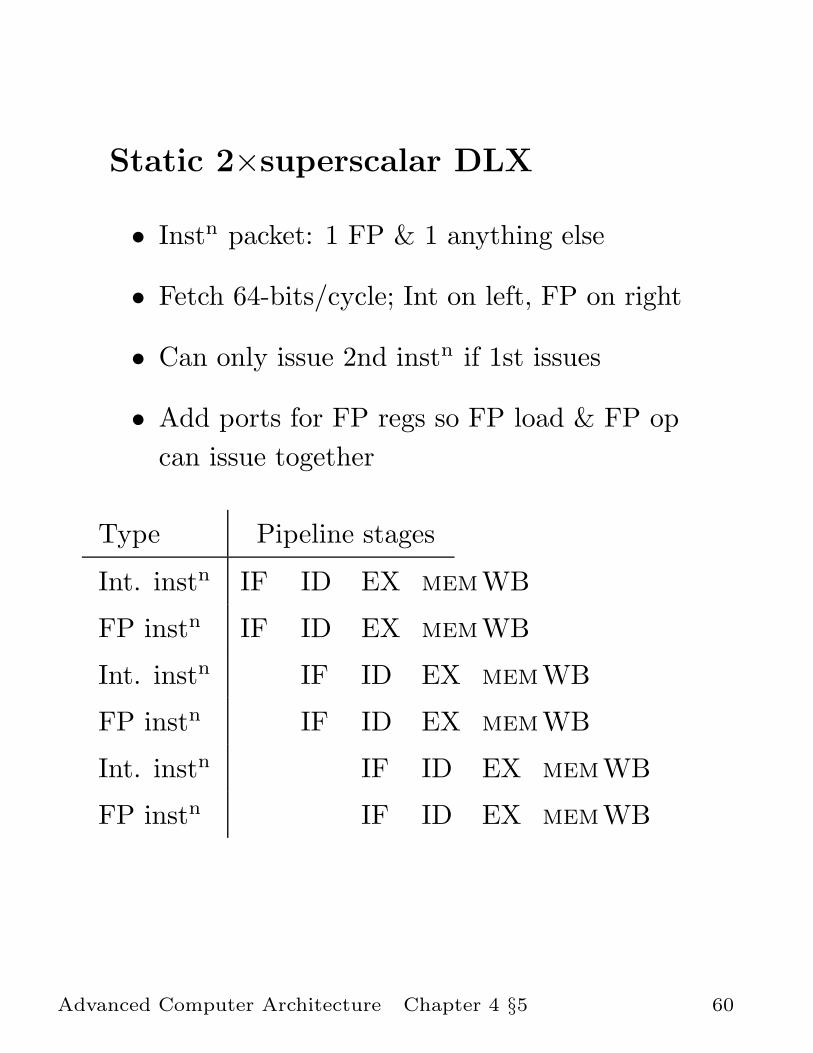
Static 2×superscalar DLX
• Instn packet: 1 FP & 1 anything else
• Fetch 64-bits/cycle; Int on left, FP on right
• Can only issue 2nd instn if 1st issues
• Add ports for FP regs so FP load & FP op
can issue together
Type Pipeline stages
Int. instn IF ID EX memWB
FP instn IF ID EX memWB
Int. instn IF ID EX memWB
FP instn IF ID EX memWB
Int. instn IF ID EX memWB
FP instn IF ID EX memWB
Advanced Computer Architecture Chapter 4 §5 60

Increased effective delays
Int: LD F0 ,100(R1) IF ID EX mem WB
FP: instn IF ID EX memWB
Int: LD R2 ,100(R1) IF ID EX mem WB
FP: instn IF ID EX memWB
Int: instn IF ID EX memWB
FP: ADDD F2, F0 ,F1 IF ID EX memWB
Int: ADD R4, R2 ,R3 IF ID EX memWB
FP: instn IF ID EX memWB
• Load delay is increased from 1 to at least
3, since instn in right half can’t use it, nor
instns in next slot
• Needs more aggressive compiler instn
scheduling
Advanced Computer Architecture Chapter 4 §5 61

Static 2×superscalar - problems
New hazards:
• While Integer/FP split is simple for the
HW, get CPI of 0.5 only for programs with
exactly 50% FP operations
Data and control hazards cause more stalls:
• Any hazard in an instn package blocks
second issue
Hardware complexity:
• If more instns issue at same time, greater
difficulty of decode and issue
• Even in 2×, ID must examine 2 opcodes, 6
register specifiers, & decide if 1 or 2 instns
can issue
(H&P pp.279)
Advanced Computer Architecture Chapter 4 §5 62

Simplifying issue...
• VLIW: tradeoff instn space for simple
decoding
• By definition, all the operations the
compiler puts in the multi-instn package
can execute in parallel
• E.g., 2 integer operations, 2 FP ops, 2
Memory refs, 1 branch
– Eg 16–24 bits per field
– Instn size at least 7 × 16 = 112
– When insufficient instruction-level
parallelism is present, instruction’s
fields are sparsely used
– Very large code size
– Increased memory bandwidth demand
due to instns
(H&P pp.284)
Advanced Computer Architecture Chapter 4 §5 63

Static SS: Branch delays
• 10%–20% of DLX instns are branches
• Average length of basic block (ie
branch-free sequence) little more that 5
• Whole basic block could fit into one instn
• But data hazards prevent this, both in
VLIW and in static superscalar
Advanced Computer Architecture Chapter 4 §5 64

IDEA: trace scheduling
• Compiler technique that schedules across
several branches
• Packs operations from most-likely path
(“trace”) into minimum no of instn words
• Using static branch prediction based on
execution profiles
• In effect, compile-time speculative
execution
• Misprediction penalty still large (though
could speculate on both branches...)
Nasty practical problem:
• Instructions executed speculatively (moved
across a branch) might cause page faults or
FP exceptions
(Software pipelining is essentially the same idea
applied to loops; see tutorial exercise)
(H&P pp.296)
Advanced Computer Architecture Chapter 4 §5 65

Dynamic superscalar (H&P pp.282)
• Dynamic scheduling should reduce
dependence on sophisticated compiler and
large no of registers
• Key issue: What hazards can block
simultaneous issue?
– Can issue dependent instns together
–...tags for dependent instns can be
issued to reservn stations concurrently
– But must check for structural stalls: all
reservn stations full, or two instns need
same one
– Issue is in-order: if instni of an n-word
package has an issue stall, it’s very hard
to issue instni+1–instnn
– (n completions/clock needs n CDBs)
• Nasty problem:
– Conditional branches
Advanced Computer Architecture Chapter 4 §5 66

Branches in a dynamic superscalar
• We want to issue a package of dependent
instns, e.g.
BEQZ R10,Label IF IS
LD F0 ,100(R1) IF IS mem mem WB
ADDD F2 , F0 ,F1 IF IS RO RO EX EX WB
LD R2 ,100(R1) IF IS mem mem WB
SUBD F3, F2 ,F4 IF IS RO RO RO RO EX EX WB
ADD R4, R2 ,R3 IF IS RO RO EX WB
Issue no. 1 2
• Suppose branch is last item of prev issue
(eg...we block issue of rest of package)
• Issue 2 mustn’t proceed speculatively
• Because it will update several registers
• These registers are used to pass values
from instn to instn
• They would have to be reinstated if the
branch were mispredicted
Advanced Computer Architecture Chapter 4 §5 67

4.6 Speculative Execution
How can we avoid blocking issue on branches?
• Tomasulo’s scheme allows values to be
passed from instn to instn without
updating registers
• So we extend it so register update is
delayed until conditional branch is resolved
• We need somewhere to stash results while
waiting to be committed
(H&P pp.308)
Advanced Computer Architecture Chapter 4 §6 68

Re-order buffer
• Re-order buffer (ROB) provides additional
registers to hold values waiting to be
committed
• ROB registers are managed like reservation
stations, waiting for service
• The ROB updates the “true” destination
register with the allocated ROB register
value
• This “commit” stage occurs in-order, so
that the machine’s programmer-visible
state is consistent
Advanced Computer Architecture Chapter 4 §6 69

Tomasulo extended with ROB
opcode operand1 operand2
Reservation Station 1 RS2 RS3
Functional Unit 1 FU2 FU3
Programmer-visible registers
R0
R1
R2
R3
R4
R5
R6
R7
Common Data Bus (CDB)
Instruction Issue
Opcode
tag assignment/register renaming
ROB0
ROB1
ROB2
ROBn
Re-order buffer registers
Re-order buffer
Update registerindexed by number
Identifierof generating FUValue, if present
Instn typeand destination
....=? Update ROB reg if tag matches
true registersavailable forreading byissue stage
Advanced Computer Architecture Chapter 4 §6 70

Sequence of events
• Issue: as before except ROB register is
allocated and passed tag of the FU which
will generate the result.
Branches are also passed to the ROB
• Execute: no change
• Write result: broadcast on CDB as before,
but result is collected in ROB register
instead of true register
• Commit: ROB register is allocated for each
uncommitted instn. Process them in order,
writing results to true destination
Note
• true registers are only updated by ROB
Advanced Computer Architecture Chapter 4 §6 71

Re-order buffer: commit
• Commit:
ROB register is allocated for each
uncommitted instn.
Process them in order, writing results to
true destination
– select ROB register of next instn in
order
– wait for values to arrive if necessary
– pass result to destination register
– ROB register is freed for reallocation
Unless instn was a branch
Advanced Computer Architecture Chapter 4 §6 72

Re-order buffer: branches
When the ROB encounters a conditional
branch, there are two cases:
• Correctly-predicted
No further action is necessary
• Incorrectly-predicted
Need to prevent updates which would arise
from mis-speculatively–executed instns still
to be committed
Action:
– Flush entire ROB contents
(so still-finishing instns broadcast
results but results aren’t collected)
– Fetch next instn from proper next PC
address
Advanced Computer Architecture Chapter 4 §6 73

Re-order buffer: subtleties
• ROB is also a good place to do memory
disambiguation and to delay memory
writes until committed
• ROB must actually commit multiple instns
per cycle if it is to keep up with multiple
issue
• What happens when a second conditional
branch is encountered before a preceding
one is committed?
• How to reduce misprediction penalty?
• How big should the ROB be?
(ROB size is sometimes called the window,
since this is the extent to which the
processor looks ahead to find work to do)
Advanced Computer Architecture Chapter 4 §6 74

Speculative execution: summary
• The tricky problem is to execute dependent
chains of instructions speculatively
• This is vital in multiple-issue processors
where effective branch delay would be huge
even if correctly predicted
• Compiler techniques like trace scheduling
and software pipelining exist, and can be
assisted by various hardware techniques
• A dynamic technique builds neatly on
Tomasulo’s scheme
• Issue stage renames destn reg to ROB reg
• ROB copies ROB regs to true destn regs in
proper execn order
• This simplifies processing of interrupts,
exceptions and page faults
• 20% of HP8000’s 3.8M transistors devoted
to instn reorder buffer
Advanced Computer Architecture Chapter 4 §6 75
Top Related