


Languages
Pages
Legal


Version 1.0 1 February 2005
Lincolnshire County Council
DEVELOPMENT ROAD SPECIFICATION AND
CONSTRUCTION 2005
To be used in the Construction of Development Roads
which are to become Highways Maintainable at the Public Expense
Lincolnshire County Council City Hall Beaumont Fee LINCOLN LN1 1DN www.lincolnshire.gov.uk © L.C.C.

Version 1.0 1 February 2005
INTRODUCTORY STATEMENT This document supersedes “Development Road Specification and Construction and Design Standards for Industrial Estate Roads 1999”. It should be read and used in conjunction with the Lincolnshire Design Guide for Residential Areas. Electronic copies of this Specification can be found on the County Council website, LCC Connects:- www.lincolnshire.gov.uk from there select Environment and Safety and then Planning and Development followed by Development. This Specificiation will be subject to review and amendment. The version of the Specification, including the Key Construction and Inspection Stage Certificates (Appendix 1) current at the time of signing the Section 38 agreement, will apply to works covered by that agreement.

Version 1.0 1 February 2005
CONTENTS Clause Page No GENERAL GUIDANCE NOTES
Introduction Planning Permission Road Layout Disposal of Road Surface Water Drawings Inspection, Testing and Reporting Permanent Traffic Signs and Road Markings Works Within the Public Highway CDM Requirements Specifications, Codes of Practices Etc Commuted Maintenance Payments
1 1 1 1 1 2 3 3 4 4 4
1. CONSTRUCTION STANDARDS 1.1 General Principles 5 1.1.1 Conformity of Standards 5 1.1.2 Variation of Approved Details 5 1.1.3 Construction Charts 5 1.1.4 Roads Carrying Over 2.0 m.s.a. 5 1.1.5 Concrete Roads 5 1.1.6 Site Investigation 5 1.1.7 Sub-grade 5 1.1.8 California Bearing Ratio Test (C.B.R.) 6 1.1.9 Carriageway Construction Thickness (Frost Susceptibility) 7 1.1.10 Laboratory Results and Test Reports 7 1.1.11 Contaminated Land 7 1.1.12 Plate Bearing Tests 8 1.1.13 Approved Suppliers, Test Methods and Working Standards 8 1.1.14 Trafficking of Binder Course 8 1.1.15 Trafficking of Roads, Contamination and Storage of Materials 8 1.1.16 Kerbing 8 1.1.17 Minimum Depth Flexible Construction 10 1.1.18 Commuted Maintenance Payments 10 General Sectional Detail (Diagram) 12 1.2 Sub-base 13 1.3 Binder Course 13 1.4 Surface Course 13 1.5 Footway Construction 13 Domestic Vehicle Crossings (Diagram) 14 Heavy Duty Access Crossing (Diagram) 15 1.6 Vehicle Access Crossings 16 1.7 Waiting Bay or Layby Construction 16 1.8 Tactile paving at crossings for pedestrians 16 Dropped Kerb Detail (Diagram) 17 Use of Tactile Paving (Diagram) 18 1.9 Small Block Pavers 19 Construction Chart 1 (Up to 0.25 m.s.a.) – Normal Flexible Construction 20 Construction Chart 2 (Up to 0.25 m.s.a.) – Min. Depth Flexible Construction 21 Construction Chart 3 (Up to 0.25 m.s.a.) – Small Block Paver Construction 22 Construction Chart 4 (Up to 2.0 m.s.a.) – Normal Flexible Construction 23 Construction Chart 5 (Up to 2.0 m.s.a.) – Min. Depth Flexible Construction 24 Construction Chart 6 (Up to 2.0 m.s.a.) – Small Block Paver Construction 25

Version 1.0 1 February 2005
2.
TYPICAL SECTIONS THROUGH CARRIAGEWAY EDGE AND FOOTWAY EDGE
2.1 Carriageway, Kerb and Footway Detail – Charts 1, 2, 4, and 5 26 2.2 Carriageway, Kerb and Footway Detail – Chart 3 and 6 26 2.3 Carriageway, Kerb and Footway Detail – Shared Surface Road Plan 27 2.4 Carriageway, Kerb and Footway Detail – Shared Surface Road Section 28 2.5 Channel Block and Kerb Detail 29 2.6 Service Margin Detail – Shared Surface 29 2.7 Chart 1 Type Road Utilising Alternative Method of Kerb Installation 30 (Two Stage Construction; Kerbing to be added at a later stage) 3. TRAFFIC AND SAFETY MEASURES DURING CONSTRUCTION 3.1 Temporary Traffic Signs 31 3.2 Control of Traffic 31 3.3 Temporary Diversion of Traffic 31 3.4 Safety Codes 31 3.5 Excavations 31 3.6 Materials on the Highway 31 3.7 Mud, etc. On the Highway 32 4. SITE CLEARANCE 4.1 Clearing site 33 5. DRAINAGE 5.1 General principles 34 5.2 Design-Layout 35 5.3 Connections to existing drains or public sewers 36 5.4 Hydraulic Design 36 5.5 Pipes and Couplings 37 5.6 Manholes 38-39 Figure 5/1 Typical manhole detail Type A 40 Figure 5/2 Typical manhole detail Type B 41 Figure 5/3 Typical manhole detail Type C 42 Figure 5/4 Typical manhole detail Type D 43 5.7 Gullies and Connections 44 Figure 5/5 Typical gulley details 45 5.8 Brickwork and Blockwork 46 5.9 Covers and Frames 46 5.10 Excavation for drainage works 47 5.11 Backfilling of trenches and filter drains 47-48 5.12 Pipelaying 49 5.13 Bedding, laying and surrounding of pipes 49-50 5.14 Inspection testing and cleansing 51-52 6. EARTHWORKS 6.1 Formation Level 53 6.2 Topsoil 53 6.3 Soiling, Grassing and Turfing 53 6.4 Embankments and Cuttings 53 6.5 Dispersal of Standing Water 54 6.6 Excavations Within Proposed Highway Limits 54 6.7 Ground Improvement 54-56 6.8 Granular Fill 56-58

Version 1.0 1 February 2005
7. ROADWORKS - OVERALL REQUIREMENTS 7.1 Horizontal Alignment, Surface Levels, Layer Thicknesses and Surface
Regularity 59-60
7.2 Compaction of Bituminous Materials 60-61 7.3 Cold Weather Working 62 7.4 Use of Surface by Constructional Plant 62 8. SUB-BASE 8.1 Type 1 Aggregate for Sub-Base 63-65 8.2 Plate Bearing Tests 65-66 9. FLEXIBLE SURFACING General 67 9.1 Dense Binder Course 67 9.2 Tack Coat 67 9.3 Close Graded Surface Course for carriageways 67 9.4 Dense Surface Course for footways 67 9.5 Rolled Asphalt Surface Course 67 9.6 Coated Chippings 68 9.7 Joints in Bituminous Construction 68 9.8 Recycled Material 68 9.9 Residual Binder Penetration 69 9.10 Coloured Surfacing for Conservation Areas and Other Environmentally
Sensitive Areas 69
9.11 Thin Surface Course Systems 69 10. SMALL BLOCK PAVERS, KERBS, CHANNELS AND EDGINGS 10.1 Kerbs, Channels and Edgings (Standard) 70 10.2 Small Block Pavers: Concrete Block Paving 70 10.3 Small Block Pavers: Clay Pavers 70-71 10.4 Small Block Pavers: Bedding Sand 71 11. CULVERTS AND SMALL RETAINING WALLS General 72 11.1 Design and Technical Approval Requirements 72 11.2 Specification 72 11.3 Basic Design Principles 72-73 11.4 Design Guidance 73 12. CONCRETE 12.1 Concrete Mixes 74 12.2 Cold Weather Working 75 12.3 Transport and Placing 75 12.4 Compaction of Concrete 75 12.5 Curing of Concrete 75 13. BRICKWORK 13.1 Brickwork: General 76 13.2 Exposed Joints (i) Pointed Joints
(ii) Unpointed Joints 76 76
13.3 Cold Weather Working 76 13.4 Facing Brickwork 76

Version 1.0 1 February 2005
14. STREET LIGHTING 14.1 Approval 77 14.2 Services 77 14.3 Standards 77 14.4 Installation 77 14.5 Completion and Commissioning Maintenance 77-78 14.6 Commuted Sums 78 15. PLANTING 15.1 Planting Within Verges 79 15.2 Trees 79 15.3 Tree Planting Detail 80 16. INDUSTRIAL DEVELOPMENT ROAD LAYOUT PARAMETERS 16.1 Heavy Industrial Estate Road 81 17. PUBLICATIONS 17.1 British Standards 82-83 17.2 Other Publications 83-84 18. APPENDICES Title page 85 18.1 Appendix 1 – Key Construction and Inspection Stage Certificates 86-122

Version 1.0 1 February 2005 1
GENERAL GUIDANCE NOTES INTRODUCTION Local Authorities, other bodies or persons developing land involving the construction of Development Roads and streets must apply in writing to the Highway Authority prior to undertaking the work, and thereafter comply in full with the requirements of this document. Any variations that may be required by or agreed with the Highway Authority shall be in writing. PLANNING PERMISSION Before making application to the Highway Authority, the Developer should first obtain planning permission from the District Council concerned for the proposal as a whole. Application for this, or approval of reserved matters in the case where an outline planning permission has already been granted, must be made to the District Council on the appropriate form obtainable from the District Council Offices. The Planning Authority will need to be satisfied before granting planning permission for development involving the construction of roads, that those roads will be laid out, constructed, lit, marked and signed in such a manner that they can be taken over by the Highway Authority for maintenance at the public expense. Prospective developers are advised, therefore, to consult the Highway Authority, if in doubt, when preparing application drawings for submission to the Planning Authority. A Developer must ensure that the proposal as a whole also meets requirements under any other legislation administered by the relevant District Council, or Lincoln City Council. ROAD LAYOUT The general layout and design of the new roads shall comply with the Lincolnshire Design Guide for Residential Areas. DISPOSAL OF ROAD SURFACE WATER The normal process for the drainage of developments is that the Developer enters into an agreement with the appropriate sewerage undertaker under Section 104 of the Water Industry Act 1991 for the design and construction of the foul and surface water sewers, which are ultimately adopted by the sewerage undertaker as public sewers. The Highway Authority in these circumstances normally only adopts the road gullies and the connections to the surface water sewer. Prospective Developers must establish that road surface water can be disposed of satisfactorily by means of an outfall approved by the Highway Authority, also establishing that they have the legal capacity to make such provision and to secure any necessary easement for the Highway Authority. DRAWINGS In addition to obtaining planning permission from the District Council, road constructional details must be approved in writing by the Highway Authority before any roadworks start. In the first instance, the Developer must provide two complete copies of the drawings and details of the proposed road or street as follows (and as shown illustratively on pages 125 & 126 of the Lincolnshire Design Guide for Residential Areas):- - Estate location to scale note less than 1:2500; - the road, the subject of the application, to a scale not less than 1:500 including full details of
surface and foul water drainage, street lighting proposals, carriageway markings and signs and all mains and services within the proposed highway;

Version 1.0 1 February 2005 2
- longitudinal sections including surface and foul water drainage to a horizontal scale not less
than 1:500 and to a vertical scale of 1:100; - typical cross sections of construction proposed and all other details in accordance with the
typical detail drawings given in this Specification; - cross sections of the road at intervals of not greater than 30 metres and to a scale of 1:100
horizontal and 1:50 vertical where the adjoining site levels vary 0.5 metres ± from finished footway levels. The cross sections must extend to the building line of the proposed properties;
- the following note shall be incorporated on all drawings submitted:- “The specification in all
respects shall be in accordance with the current Lincolnshire Design Guide for Residential Areas” and “Development Road Specification and Construction” publications in force in the County at the time of construction.
INSPECTION, TESTING AND REPORTING Developers are reminded of the requirement to enter into a Section 38 Agreement with the Highway Authority. Any works carried out prior to such an Agreement will not be adopted unless the Developer can prove their acceptability by means of additional testing and interpretive reports. In such cases the County Council must ensure that construction has been carried out to an acceptable standard as required by this specification. All requirements of this document must be demonstrated to have been met. There must be documentary evidence of a site investigation that satisfies that all the requirements of the specification have been carried out, and that the correct construction thicknesses are in place. Furthermore evidence of end product testing in terms of the bearing capacity of the sub-base and air voids, bond and thickness of the bituminous layers must be produced. If any of the above requirements are not satisfactory supplied, retrospective investigation and reporting, at the developer’s cost, will be required before adoption will be considered. If such works are found to be defective, they will need to be taken out at the Developer’s expense. All additional testing costs shall be borne by the Developer. In addition, the County Council would require the developer to pay a sum to be determined by the County Council to meet possible future risk to the Authority due to the lack of inspection, testing and certification at the correct stage. The developer’s attention is drawn to the certification process which the County Council now operates for development roads and the requirement; in accordance with the Section 38 Agreement, to have a nominated person who is responsible for managing construction and quality of the development. This person will be responsible for notifying in good time (a minimum of 5 working days notice) and providing facility for the authorised representative of the County Council to carry out the initial inspections and tests and obtain the subsequent certificates for the 8 key stages of construction and 2 key stages of inspection as detailed below:- Key Stage of Construction 1 – Drainage Key Stage of Construction 2 – Site Investigation/Formation/Earthworks/Geotextile Key Stage of Construction 3 – Carriageway Sub-base Key Stage of Construction 4 – Kerbing and Channelling Key Stage of Construction 5 – Carriageway Binder Course Key Stage of Construction 6 – Footways and Edging Key Stage of Construction 7 – Block Paved Areas Key Stage of Construction 8 – Carriageway Surface Course Key Stage of Construction 9 – Pre-Maintenance Period Inspection Key Stage of Construction 10 – Pre-Adoption Inspection

Version 1.0 1 February 2005 3
Should the developer fail to give sufficient notice (a minimum of 5 working days) and provide adequate facility for an authorised representative of the County Council to inspect test and certificate the above key stages of construction at the correct time, the County Council will require retrospective testing to be carried out at the Developer’s expense and in addition the Developer will be required to pay sums to the County to meet any possible future risk to the Authority due to any lack of proper inspection and testing at the appropriate stages. Appendix 1 of this specification has example certificates and details of the inspection, testing and certification process. PERMANENT TRAFFIC SIGNS AND ROAD MARKINGS Where it is deemed by the Highway Authority that, in the interests of highway safety and/or required by regulations, traffic signs are required to be erected and/or road markings need laying, as part of the development Developers will have to provide them at their cost. All traffic signs shall be designed and erected in accordance with the current “Traffic Signs Regulations and General Directions”, the “Traffic Signs Manual” and any amendments and extensions thereof. For Directional, informatory or warning signs with supplementary plates, a detailed drawing of the sign’s face must be provided to Traffic Signs Section for approval – guidance may also be given on the required signing by this section if necessary. All traffic signs shall have a minimum guaranteed life of not less than 7 years; this guaranteed life must be not less than 10 years for Class 1 or Micro prismatic materials. Road markings shall be in accordance with BS EN 1436 and shall have the following minimum standards of performance for a minimum period of 2 years from the date of application. Table G/1 Performance Standards for Road Markings Property BS EN 1436
Reference Requirement* Value
Colour Table 6 1. White 2. Yellow Class Y1, Y2
X, Y co-ordinates given X, Y co-ordinates given
Luminance Factor
Table 5 1. Class B2 2. Class B1
0.3 0.2
Skid Resistance
Table 7 1. Class S1 2. Class S1
45 45
Retroreflectivity Table 2 Class of RL for dry markings
1. Class R2 2. Class R1
100 80
Retroreflectivity Table 3 Class of RL for road markings in conditions of wetness
Class RWD No Requirement
* Note: 1 = White, 2 = Yellow WORKS WITHIN THE PUBLIC HIGHWAY Any necessary off site excavations carried out in the existing public highway will require permits under the New Roads and Street Works Act (NRSWA) 1991 and/or permission under the Highways Act 1980. These can be obtained from The Director of Highways and Planning. Such permits and permissions will only be granted by the County Council as Highway Authority once the Developer has signed and completed the Section 38 Agreement. Should the developer enter onto the existing highway in advance of this, then their excavations will be considered illegal interference with the highway and appropriate enforcement action will be instigated. All works conducted within the public highway must be carried out and maintained to the satisfaction of the Highway Authority.

Version 1.0 1 February 2005 4
CDM REQUIREMENTS In accordance with Regulation 12/2 of the CDM Regulations 1994, once their site is adopted Developers must pass to the Highway Authority their Health and Safety file for any structure, i.e. culverts, highway drains and the road itself. The Developers Planning Supervisor should ensure the Highway Authority is given this file which must include factors which could influence future maintenance e.g. land contamination areas, maintenance of drains and culverts, etc. SPECIFICATIONS, CODES OF PRACTICES ETC References made to Specifications, Codes of Practices, etc are current at the time of publication. Where any are superseded by new documents reference shall be made to the most up-to-date edition. COMMUTED MAINTENANCE PAYMENTS In the event of Developers proposing alternative materials and features to those detailed in this specification attention is drawn to Clause 1.1.18. Such materials and features are often more expensive to replace and or have a shorter lifespan than those specified. In view of this the Highway Authority makes a charge to cover the additional maintenance costs for such materials and features.

Version 1.0 1 February 2005 5
1. CONSTRUCTION STANDARDS 1.1 GENERAL PRINCIPLES 1.1.1 Conformity of Standards The construction methods, materials and standards adopted shall conform with the following
except where varied by this specification:- (i) The relevant British (and relevant European) Standard specification (ii) The Highways Agency’s current Specification for Highway Works (iii) TRL Laboratory Report 1132 - “The Structural Design of Bituminous Roads” (iv) The Highways Agency’s current Pavement Design and Maintenance Manual (Volume 7) (v) Lincolnshire County Council Highways and Planning Directorate Code of Practice -
“Highway Works: Standards, Materials, Testing - HT/14/1/94”. 1.1.2 Variation of Approved Details Details shall be to the satisfaction of the Highway Authority and any variation from the details
approved must be communicated in writing and agreed in writing prior to the variation work being undertaken.
1.1.3 Construction Charts Construction Charts 1, 2 and 3 shall be used for Housing Development Roads carrying up to
0.25 million standard axles (m.s.a.). Construction Charts 4, 5 and 6 shall be used for Housing Development Roads carrying between 0.25 m.s.a. and 2.0 m.s.a. and all Light Industrial Roads. The charts set out minimum standards of carriageway construction related to the bearing capacity of the sub-grade (CBR) and the weight and volume of the traffic using the particular road.
1.1.4 Roads Carrying Over 2.0 m.s.a. The requirements of this specification apply to all Development Roads. Those intended to
serve anticipated traffic categories in excess of 2.0 m.s.a. over a 40 year lifespan will require individual carriageway designs using the principles incorporated in TRL Laboratory Report 1132 or the Highways Agency’s current Pavement Design Manual (Volume 7). In these instances the Construction Charts in this specification are superseded.
1.1.5 Concrete Roads The construction charts do not include concrete roads and unless the Developer can produce
overriding reasons for their use, they will not normally be permitted. If instances do arise where concrete construction is to be used, the design must be in accordance with the Highways Agency’s current Pavement Design and Maintenance Manual (Volume 7). The design must be approved in writing prior to construction commencing and due to the amount of supervision and quality control tests necessary in the use of concrete, the Highway Authority will levy an additional supervision charge on an actual cost basis.
1.1.6 Site Investigation It is important that the site investigations carried out are adequate in extent and quality. The
site investigation must be in accordance with BS 5930 : 1999 and where appropriate BS10175:2001. The following items must be included within the report together with any other relevant information and an interpretative section.

Version 1.0 1 February 2005 6
a) The proposed works covered by the report; i.e. highway design, b) Site Description; to include descriptions of topography, boundaries, access,
vegetation, water features, ditches, the presence of any structures or anything else which may be of importance to the future use of the site.
c) Geology; a prediction of the site’s geology which includes reference to British
Geological Survey publications. In the section of the report which discusses the findings, a cross reference to the predicted site geology and found site geology must be made. All exploratory hole logs must summarise the interpreted geology for each stratum.
d) History; to include all known past use of the site which includes reference to present
and past Ordnance Survey maps.
e) Site Work; details of exploratory holes and/or trial pits encountered at the site. Exploratory holes should normally be spaced between 50m and 100m adjacent to the line of the proposed carriageway and encounter all the soil types on the site. Sufficient samples of each soil type must be taken from appropriate depths and tested at the relevant moisture content. For CBR testing, samples must be taken from the anticipated formation level to 0.5m below, except where there are different soil types when the weakest material must be sampled and tested. In-situ and laboratory testing should be undertaken as appropriate. Additional exploratory holes should be undertaken where ground conditions are variable; particularly where they are weak.
If CBR tests are not undertaken during the site investigation the CBR value is to be
assumed to be below 1½% and the construction thickness provided as shown on Charts 1-6. This can only be assumed to be the case if the site investigation indicates the ground to be suitable. Obviously costs can be saved by conducting CBR tests.
f) Laboratory Work; must include an indication of where the testing was carried out
and a comment on the accreditation status for each test carried out. g) Contamination; the site must be classified as ‘brownfield’ or ‘greenfield’. All
brownfield sites must be subject to contamination testing and an environmental risk assessment. Testing for contaminants on greenfield sites need only be carried out if a specific reason to do so is identified. Further details are given in clause 1.1.11.
1.1.7 Sub-grade The construction charts give alternative construction treatments for localised soft spots. If
either the sub-grade or soft spots have a CBR below 1½% then specialist advice is required. It may be necessary to provide sub-grade drainage or other soil strengthening techniques such as incorporating a geosynthetic product (Clause 6.7.1) or stabilisation (Clause 6.7.2).
The depth and type of treatment and the form of construction of the carriageway to be used must be agreed before the work commences. A Developer may consider the use of a geosynthetic product which has two principal uses in a pavement foundation. The first is as a separator between the sub-base and sub-grade. The second is as a foundation reinforcing agent which can reduce the sub-base thickness with consequential economies in construction.
The type of geosynthetic product to be used, its purpose and any proposed reduction in sub-base thickness must be agreed before construction commences (Clause 6.7.1).
1.1.8 California Bearing Ratio Test (CBR) CBR samples must be recovered in conjunction with a site investigation carried out in
accordance with Clause 1.1.6. The relevant CBR compaction method is described in BS 1377 (1990) Part 4 Clause 7.2.4.4 Method 5. Where more than 25% of material is retained on the 20mm sieve, advice shall be sought from a suitably qualified engineer. The engineer will advise the laboratory on what action to take with the material >20mm. The sample to be tested is to be a representative sample taken between the anticipated formation level and 0.50m below formation and should be compacted with a 2.5kg hammer and normally tested with six 2kg surcharge weights.

Version 1.0 1 February 2005 7
The resultant CBR is used in conjunction with the Construction Charts to develop the
pavement design. However, because cohesive soils are moisture susceptible their strength may vary due to changes in water content before or after construction. In the absence of evidence to the contrary the maximum acceptable design CBR on cohesive sub-grades on all roads is 3%.
1.1.9 Carriageway Construction Thickness (Frost Susceptibility) When CBR tests have been carried out, the thickness given in the tables may be used.
Additionally, if tests show the sub-grade to be non frost susceptible, then further economies in the thickness may be made. In such cases any proposed reduction in sub-base thickness must be agreed before construction commences.
For frost heave, materials shall be tested in accordance with BS 812: Part 124 as amended
by Clause 801 of the Specification for Highway Works Volume 1 2004 except that the use of the silica sand and limestone filler reference specimens is not mandatory.
Materials are classified as non frost susceptible if the mean heave is 15.0mm or less. 1.1.10 Laboratory Reports and Test Results The Highway Authority will accept reports containing test results only from UKAS Accredited
Laboratories which are specifically accredited for the tests in question. The County Council’s Materials Laboratory - Lincs Laboratory will offer further advice on this matter if requested to do so, and are able to carry out materials testing and consultancy work on a rechargeable basis. Lincs Laboratory is a UKAS Accredited Laboratory (Testing No 0699). Correspondence should be addressed to:- The Laboratory Manager, Lincs Laboratory, St George’s Lane, Riseholme, Lincoln LN2 2LQ, telephone: (01522) 530355, fax: (01522) 510573 or E-mail [email protected]
1.1.11 Contaminated Land This is any land that contains substances which, when present in sufficient quantities or
concentrations, are likely to cause harm, directly or indirectly to man, to the environment or on occasions to other targets. In the event of the Developer or any individual working on the Developer’s behalf encountering or having suspicion of encountering contaminated ground, the Highway Authority shall be informed at the earliest opportunity. Any contaminated land encountered will need to be investigated and reported in accordance with Clause 1.1.6. This is relevant on all “Brownfield” and filled sites.
An environmental risk assessment shall be undertaken based on:
i) history of past use ii) visible signs of contamination or dumping iii) chemical analysis of samples when contamination is strongly suspected
The risk of potential harm to the environment, workforce, visitors, and end users shall be
made referencing the hazard-harm-pathway-target model. The result of the risk assessment shall be in the format:
No or little risk – no action Significant or real risk – some action to mitigate or reduce risk. Very significant or serious risk – action to remove the hazard or pathway. Highly significant or very serious risk – removal of hazard will take priority over construction
considerations.

Version 1.0 8 1 February 2005
1.1.12 Plate Bearing Tests It is important that unbound granular materials are not segregated and are adequately
compacted. Attention is specifically drawn to Clause 8.1. The Highway Authority will carry out Plate Bearing Tests to ensure compliance with this requirement.
1.1.13 Approved Suppliers, Test Methods and Working Standards All materials shall be obtained from a source currently approved by the Highway Authority.
The current list of suppliers is maintained by Lincs Laboratory and can be accessed via the Lincs Lab webpage. This can be accessed by logging onto the County Council website (www.lincolnshire.gov.uk), and going to Transport and Roads, Lincs Lab web page and then Brochures and Downloads. Developers are advised to ensure that contractors working on their behalf are experienced in working to the standards required by the Highway Authority.
Prior to conducting tests on behalf of the Developer, the Test House shall submit details of the Test Procedure to be used to the Lincs Laboratory. Testing shall not take place until the Test House has received approval for the proposed Test Procedure.
Developers are required to inform the Highway Authority of proposed material suppliers and
sources and sub-contractors to be used, prior to the commencement of any such elements of work being conducted.
1.1.14 Trafficking of Binder Course The Developer’s attention is specifically drawn to the effect of trafficking exposed binder
course materials prior to the application of the final surface course. The binder course shall be thoroughly cleaned and a tack coat to Clause 9.2 applied prior to the laying of the surface course. It may be necessary to use high pressure washing equipment if heavy contamination has occurred. Prolonged exposure to trafficking may result in the binder course becoming so adversely affected that its replacement will be necessary prior to laying the surface course. The use of sealing grit to BS 4987-1:2003, to protect the binder course if it is likely to be significantly trafficked is permissible. All traces of sealing grit shall be removed prior to the application of the surface course.
1.1.15 Trafficking of Roads, Contamination and Storage of Material Traffic in connection with the related housing/building development must not use roads until
constructed to the requirements of this specification. It is important that materials used in the construction of the areas to be adopted are not contaminated. Control should be such that only vehicles and plant associated with the roadworks be allowed to traffic the formation level and sub-base layers before and during construction. Formation that is damaged and sub-base that becomes contaminated by materials used in adjoining building works, top soil, clay, etc will not be adopted. At no stage during the construction of carriageways shall materials associated with the adjoining building works be stored thereon.
1.1.16 Kerbing Kerbs shall be installed prior to the full depth of the carriageway binder course being
placed, unless the alternative working practice detailed below is employed. The Developer’s attention is drawn to the need to protect laid lengths of kerbing, channels
and edgings. It may be necessary for this protection to take the form of a physical barrier such as concrete over protection with a polythene or geotextile membrane.
All damaged kerbs, channels and edgings shall be replaced prior to the application of
carriageway or footway final surface course. Where more than 4 separate kerbs, channels or edgings are damaged within any 10m length, the entire 10m length must be replaced, using undamaged kerbs, channels or edgings in accordance with the specification.
Where it becomes necessary to replace kerbing, channels or edgings damaged following the
application of final surface course to footway or carriageway, a minimum 2m length of Surface Course, full width of the footway, shall be replaced. If damage is caused to the adjacent carriageway surface course the surface course shall be replaced for a minimum of 5m for half

Version 1.0 1 February 2005 9
the width of the carriageway. This Clause shall also apply where the Developer wishes to make minor changes to laid kerbing e.g. when adjusting the position of a vehicular crossing.
The kerb/channel bed, on development roads shall, always be laid separate to the backing as
shown on the typical sections through carriageway edge details on pages 25, 26 and 27. This is due to the high level of kerb damage experienced on development roads and the resulting need to replace kerbs at a late stage of construction whilst causing the minimum damage to the overall construction. In addition should the alternative kerb installation methods below be employed then the separate kerb bed/race can be utilised as level control for the first layer of binder course.
For roads constructed in accordance with Construction Chart 1 the alternative method of
kerb installation (two stage construction; kerbing to be laid at a later stage) is as follows:-
The initial layer of binder course shall be 70mm thick. Kerbing to be installed prior to laying a further 60mm layer of binder course and the 40mm of surface course. Kerb bed/race laid prior to initial layer of binder course to assist with level control. Where the CBR of the sub-grade is less than 1½% specialist advice must be sought in accordance with Clause 1.1.6, with a bespoke design being employed. Lincs Laboratory shall be consulted in these circumstances.
The alternative kerb installation method (two stage construction – kerbing to be laid at
a later stage) for roads constructed in accordance with Construction Charts 2, 4 and 5 is as follows:-
Any appropriate combination of binder course layer thicknesses in accordance with this
Specification may be used providing:-
The initial binder course layer shall not be thinner than 110mm. All subsequent layers of binder course must be at least 60mm thick with at least one 60mm layer being placed after the installation of the kerbing. The overall specified thickness of binder course shall be increased by 10mm. Where the CBR of the sub-grade is less than 1½% specialist advice must be sought in accordance with Clause 1.1.6, with a bespoke design being employed. Lincs Laboratory shall be consulted in these circumstances.
Should a Developer wish to employ an alternative method of kerb installation as detailed
above, this should be shown on the typical sections and drawings submitted for approval detailing the construction details and processes to be employed and the combination of layer thicknesses to be used. Particular account, by the Developer, shall also be made of the following points:-
Additional construction layer interfaces are being introduced and attention is drawn to the
requirement to achieve bond between all bituminous layers in accordance with Clause 7.2. Attention is drawn to the general requirement for all carriageway binder course to be 50 pen
material in accordance with Clause 9.1. Attention is also drawn to the requirements of Clause 7.4, in that constructional plant shall be
suitable in relation to the thickness of the pavement course to be traversed so that damage to the pavement course of the carriageway or the sub-grade material is not caused. The first layer of binder course must not be damaged or over stressed by construction plant.

Version 1.0 1 February 2005 10
1.1.17 Minimum Depth Flexible Construction Charts 2 and 5 provide alternative flexible designs based on the principle of replacing some
of the granular foundation with bituminous material, known as ‘bituminous replacement’. Highway construction practice on these thin foundations will have to be reviewed, normal procedures may not be appropriate due to the reduced ability of the foundation to carry construction traffic e.g. tracked rather than wheeled pavers to lay the binder course. Construction must be phased such that any excavated area is covered the same day with sub-base and this protected to prevent the ingress of water.
The sub-base shall conform with Clause 8.1 and shall be Type 1. Since part of the normal
granular foundation has been replaced with bituminous material the in-situ CBR requirement on top of the sub-base is not appropriate. Instead the sub-base shall comply with the in-situ density requirement stated in Clause 8.1. This sub-base layer is not designed to carry other construction traffic.
When the sub-grade CBR is 3% or less consideration should be given at the site investigation
stage to incorporate a geosynthetic separator at the sub-grade/sub-base interface. Minimum depth flexible construction is not permitted on any site where the site investigation has identified a risk from soil shrinkage and heave.
The two design charts provide for frost protection when the sub-grade is classified as frost
susceptible. Additional bituminous material has been included to provide the protection rather than increasing the thickness of non-frost susceptible Type 1 sub-base as in the normal flexible charts. Research has revealed that dense bituminous material offers added protection due to its increased insulating effect and by limiting water penetration into the pavement structure.
1.1.18 Commuted Maintenance Payments
Alternative materials and features to those detailed in this specification are often more expensive to replace or have a shorter service life to those specified.
The additional costs associated with assessing such alternatives, including testing, will normally be borne by the proposer and the County Council will require certain commuted sums to be paid by the developer for additional maintenance costs as follows:- i) Surface Water Drainage Systems
The Highway Authority normally only adopts the road gullies and the connections to the surface water sewer. Where the Highway Authority is to adopt certain highway only drainage infrastructure (other than for gully connections) the developer will be required to pay Commuted Maintenance payments calculated by the Highway Authority. The Highway Authority will not consider for adoption any systems which collect roof, curtilage water and/or land drainage.
ii) Sustainable Drainage Systems (SuDS)
Sustainable Drainage Systems (SuDS) and above-ground attenuation systems have been proposed as solutions for dealing with surface water flows in environmentally friendly ways; however, the Highway Authority is generally constrained to only accepting pipe systems for adoption. Therefore as these may put an additional burden on the Highway Authority a Commuted Sum is required.
iii) Soakaways
Soakaways may be considered for adoption in exceptional circumstances but only on small sites where there is no positive outfall within reasonable proximity to the site. A commuted sum will be required as above.

Version 1.0 1 February 2005 11
iv) Non Standard Surfacings and alternative materials
Where surfacing materials are proposed that are not with the current specification a commuted sum will be required to cover the additional replacement costs and maintenance costs over the lifetime.
v) Structures
Major structures such as retaining walls, bridges etc will require a commuted sum to cover replacement cost and maintenance.
vi) Street Lighting
Commuted sums for street lighting are charged where, in the opinion of the Highway Authority the requirements of the developer are over and above what would normally be specified for each particular development.
vii) Planted Areas
Any proposed grassed area and/or areas with approved trees or shrubs, within the adoptable highway, other than standard highway verges, also require a commuted sum to cover maintenance.
Where items, as listed above, in this clause are proposed, the developer will be informed that a commuted maintenance payment will be written into the Section 38 Agreement.

Geo
text
ileTo
psoi
l bel
ow s
eede
d ve
rge
Roa
d G
ulle
y
Surf
ace
Wat
er S
ewer
- W
ater
Aut
hori
tyH
ighw
ay D
rain
- Li
ncol
nshi
re C
ount
y C
ounc
il
Foot
way
Gul
ley
Foul
Wat
er S
ewer
- W
ater
Aut
hori
ty
Sub
base
Bin
derc
ours
eSu
rfac
e C
ours
e1
in 4
01
in 4
0
1 in
250
1 in
150
1 in
25
Cha
nnel
Blo
ck /
Ker
bjo
ints
to b
est
agge
red
onst
raig
hts.
GEN
ERA
L SE
CTI
ON
AL
DETA
IL(N
B R
EFER
TO
SPE
CIF
IC D
ETA
ILED
SPE
CIF
ICA
TIO
NS)
12
1 in
30
See Drawing Ref Clause1.6(a) for detail

Version 1.0 1 February 2005 13
1.2 SUB-BASE Sub-base shall conform with Clause 8.1 and shall be Type 1. A minimum in-situ CBR value
of 20% will be required on all roads except for Development Roads intended to serve heavier traffic categories (i.e. loading in excess of 0.25 m.s.a.) where the in-situ CBR value should be at least 30%. CBR values shall be determined by Plate Bearing Tests in accordance with Clause 8.2.
For carriageways and footways, not more than one in ten field dry density determination, as
detailed in BS 1377:Part 9, (clause 2.2) shall be less than 90% of the maximum dry density for that particular sub-base as determined by the vibrating hammer test in BS EN 13286-3.
1.3 BINDER COURSE For carriageways, Binder Course materials shall be 0/20mm size recipe mix Dense Binder
Course to Clause 9.1 and shall be laid in a single layer or combination of layers not less than 50mm in thickness nor greater than 110mm in thickness. Compaction must be in accordance with Clause 7.2 to a void content within the range 2%-8% and all layers must be bonded together.
1.4 SURFACE COURSE For Charts 1 and 2 the Surface Course shall be 40mm of 0/10mm size Close Graded Surface
Course to Clause 7.3. It must be compacted in accordance with Clause 7.2 to a void content within the range 2%-10%.
For Charts 4 and 5 the Surface Course must be 40mm of Hot Rolled Asphalt to Clause 9.5 to
a void content within the range 2%-6%. Exceptionally 40mm of a Lincolnshire County Council approved thin surface course system may be used in place of hot rolled asphalt. The Developer must obtain the agreement of the Highway Authority for the use of the particular thin surface course system at an early stage.
The Surface Course must be bonded to the Binder Course. 1.5 FOOTWAY CONSTRUCTION This shall comprise:- a) Bituminous Surfacing 100mm of Type 1 sub-base to Clause 1.2 50mm of 0/20mm size Dense Binder Course to Clause 9.1 compacted to a void content within
the range 2%-10%. 25mm of 0/6mm size Dense Surface Course to Clause 9.4 compacted to a void content within
the range 2%-10%. The Surface Course must be bonded to the Binder Course. b) Block Paved Footways 100mm of Type 1 sub-base to Clause 1.2. 50mm of bedding sand to Clause 10.4. 60mm small unit block pavers to Clause 10.2 or 10.3. Jointing sand shall be to Clause 10.4. Block paved footways are only permitted where the adjacent carriageway is constructed with
block pavers to Chart 3 or Chart 6.

2.4m
Min
imum
Sta
ndar
ds3
Dro
pped
ker
bs fo
r a s
ingl
e cr
ossi
ng7
Dro
pped
ker
bs fo
r a p
aire
d cr
ossi
ng
For n
arro
w ro
ads
or w
here
geo
met
ry d
icta
tes
4or
mor
e ke
rbs
will
be
requ
ired
A
A
Gra
dien
t to
be 1
in 2
5
Min
6.0m
DO
MES
TIC
VEH
ICLE
CR
OSS
ING
(REF
. CLA
USE
1.6
(A))
ST3
Con
cret
e
380
150
150
150mm min.
125
x 15
0 D
ropp
ed K
erb
Gra
dien
t 1 i n
25
110
25
Sect
ion
A : A
See
Cla
use
1.6
14
Mor
tar B
ed

Widt
h Var
ies
1 in 25
Highway Boundary
"R"
125 x 255 P.C. Concrete ChannelBlocks if restraint not otherwise present
Kerb tops and channel blocks flush atthis point
Verges may be ommitted
125 x 255 P.C. Concrete ChannelBlocks required if installed along
adjacent carriagewayand/or adjacentcarriageway is not surfaced with hot
rolled asphalt
P.C. Concrete kerbs laid to radius "R"as specified by planning condition
Tactile paving
All Dimensions given in mm.
Kerbs to be dropped at intersection withfootway to 25mm upstand or flush if tactile
paving required
HEAVY DUTY VEHICLE ACCESS CROSSING(Ref Clause 1.6(a))
15

Version 1.0 1 February 2005 16
1.6 VEHICLE ACCESS CROSSINGS (A) Light Duty (Domestic) crossings 150mm of Type 1 sub-base to Clause 1.2. (NB where the CBR value of the sub-
grade is below 2% an approved geosynthetic layer to Clause 6.7 will be required to be placed on the sub-grade). On certain sites the depth of topsoil may exceed 275mm. On such sites topsoil containing organic matter, roots, etc. shall be removed and replaced with Type 1 sub-base in accordance with Clause 1.2.
100mm of 0/20mm size recipe mix Dense Macadam Binder Course to Clause 9.1
compacted to a void content within the range 2%-10%. 25mm of 0/6mm size Dense Macadam Surface Course to Clause 9.4 compacted to a
void content within the range 2%-10%. The joint between the access crossing and the carriageway shall be formed with
125mm x 150mm precast concrete kerbs on a 150mm x 380mm base of ST3 (15N/mm²) concrete (approx. 1 cement:2 sand:4 aggregate by volume mix). A 125mm x 150mm x 225mm taper kerb will be required on each side of the crossing along the carriageway edge.
The highway boundary shall be delineated across the access crossing with 50mm x
150mm square cut precast concrete edging on a 75mm x 330mm base of ST3 (15N/mm²) concrete, and where there is no footway the edges of the access crossing shall also be delineated with the same edging and base (see Drawing Ref Clause 1.6(A)).
(B) Heavy Duty Vehicle Access Crossings The construction and thickness shall be the same as the adjacent carriageway with
the proviso that in all cases the surface course shall be hot rolled asphalt to Clause 1.4. Radii kerbing shall be used each side of the crossing, dropped at the point of intersection with adjacent footways and tactile paving shall be provided each side when required (see Drawing Ref Clause1.6 (B)).
Channel blocks, not dropped kerbs shall be used at the front of these crossings if
channel blocks are installed along the adjacent carriageway and/or the adjacent carriageway is not surfaced with hot rolled asphalt. Channel blocks shall be installed at the rear of such crossings unless alternative restraint is available.
(C) Small Block Pavers Small unit paver construction will be permitted for access crossings only when the
adjoining footway is of that construction type. The materials utilised and thickness employed in the crossings shall be the same as the adjoining carriageway.
1.7 WAITING BAY OR LAY-BY CONSTRUCTION Construction shall normally be as for the adjoining carriageway. 1.8 TACTILE PAVING CROSSINGS FOR PEDESTRIANS Blister tactile paving crossing points shall be provided at all junctions, crossings at link
footways and at kerb to kerb flat top road crossings. Tactile paving to be ‘Dimple’ blocks, 450mm x 450mm x 50mm. Surface colour to be buff.

DROPPED KERB DETAIL PRIOR TO INSTALLATION OF BLISTERSURFACE
Rear of footwayStandard kerb
Taper/dropper kerb
Central channel blocks min1.8m to be flush withcarriageway surface
To enable standard dropper kerbto be used a larger joint may be
necessary for kerbs be flush withthe carriageway as specified
Kerb Carriageway
Footway
Variable width as specified but must notbe less than that required to achieve a
maximum gradient of 8% (1:12)
Preferred carriageway surface level
Minimum carriageway surface level
Footway
Not
gre
ater
than
6m
m
17

USE OF TACTILE PAVING AT PEDESTRIANCROSSING POINTS
18
UNCONTROLLED CROSSING AWAY FROMJUNCTION
1.2m
min
1.2m min
450 x 450 Tactile slabs
UNCONTROLLED CROSSING POINT AT JUNCTION
6m ra
dius 6m
radiu
s
FLAT TOP HUMP
1.8m
CROSSING POINT AT RAISED PLATFORM
CROSSING POINT AT LINK FOOTWAY
1.2m
min
800m
m

Version 1.0 1 February 2005 19
Tactile paving shall be installed in the line of travel, along the full length of a minimum of 1.8m flush dropped channel blocks. Flush kerbs to comprise 152mm x 152mm precast concrete channel blocks. The depth of the paving will be 1.8m or 450mm depending on its location (see drawings on page 17). The back edge of the tactile paving surface shall be at right angles to the direction of crossing
Developers shall take care not to locate service boxes (e.g. BT) where tactile paving is
required. 1.9 SMALL BLOCK PAVERS Concrete blocks and clay pavers shall comply with Clause 10.2 and 10.3. They shall be laid
in accordance with the requirements of BS 7533-3. Herringbone bond pattern is required for all block paved areas. Only rectangular shaped
blocks will be permitted. The layout of blocks/pavers and details at edges, manholes, gullies and other openings shall be as recommended by the supplier and agreed with the Highway Authority in advance of laying. The developer may traffic the carriageway after the placement of the bituminous binder
course across the full width of the carriageway provided that the thickness of the binder course is in accordance with the relevant Construction Chart.
When the block paver construction is to be completed prior to building being commenced
then the thickness of the binder course layer quoted in Construction Chart 3 for roads up to 0.25 m.s.a. may be reduced to 60mm. The sub-base shall be correspondingly increased by 30mm in such cases.
Bedding and jointing sand used in conjunction with small block pavers shall be in accordance
with Clause 10.4.

Version 1.0 1 February 2005 20
CONSTRUCTION CHART 1
ROADS UP TO 0.25 m.s.a. - NORMAL FLEXIBLE CONSTRUCTION
SUB-GRADE Note 1 SUB-BASE (mm) SURFACING (mm)
TOTAL THICKNESS REQUIRED (mm)
Bearing Capacity (CBR)
Without geosynthetic
With geosynthetic
Binder Course Surface Course Without geosynthetic
With geosynthetic
Below 1½% & soft spots
1½% 2% 3%
4%Note 7
5%Note 7
6-15%Note 7
Above 15%Note 7
Not suitable Not suitable
400 310 300 300 300 300
710Notes 2&3
440
340 300
300 Note7
300 Note 7
300 Note 7
300 Note 7
Notes 4&5 110 110 110 110 110 110 110 110
40 40 40 40 40 40 40 40
Not suitable Not suitable
550 Note 6
460 Note 6
450 Note 6 450 Note 6 450 Note 6 450 Note 6
860Notes 2,3&6
590 Note 6
490 Note 6
450 Note 6
450 Notes 6 &7
450 Notes 6 & 7
450 Notes 6 & 7
450 Notes 6 & 7
Note 1 See Clauses 1.1.6 and 1.1.7 Note 2 See Clause 1.1.6 – Assumes no improvement is possible using either sub-soil drainage or soil strengthening technique. 710mm is
410mm of 6F5 Capping Layer Granular Fill to clause 6.8 and 300mm of Type 1 sub-base. The thickness of 710mm can be reduced to 620mm if all Type 1 sub-base is used.
Note 3 For soft spots and sub-grades with a CBR of less than 1½% the geosythetic shall be an approved geogrid. Note 4 May be laid in one layer. Note 5 Initial Binder Course layer thickness 70mm if the alternative kerbing installation method (two stage construction – kerbing to be
laid at a later stage) is used. Total Binder Course thickness becomes 130mm in these circumstances. See Clause 1.1.17. Note 6 Total thickness to be increased by 20mm above these values if the alternative kerbing installation method is used. See Clause 1.1.17. Note 7 The use of a geosynthetic with a sub-grade with this bearing capacity offers no advantage or economy.

Version 1.0 1 February 2005 21
CONSTRUCTION CHART 2
ROADS UP TO 0.25 m.s.a. - MINIMUM DEPTH FLEXIBLE CONSTRUCTION (See Clause 1.1.18)
SUB-GRADE Note 1 SUB-BASE (mm) SURFACING
TOTAL THICKNESS REQUIRED (mm)
Bearing Capacity
(CBR)
Non-frost susceptible
Type 1
Binder Course
Surface Course
When sub-grade is classified as
frost susceptible
Below 1½% & soft spots 1½% 2% 3% 4% 5%
6-15% Above 15%
Note 2 Note 2
150 150 150 150 150 150
Note 3
200 200 200 200 200 200 200 200
40 40 40 40 40 40 40 40
Note 2 Note 2
390 Note 6 390 Note 6 390 Note 6 390 Note 6 390 Note 6 390 Note 6
Note 1 See Clauses 1.1.6 & 1.1.7 Note 2 See Clauses 1.1.6 & 1.1.18 Requires at least 150mm Type 1 Sub-Base plus an approved sub-soil strengthening technique.
Note 3 Initial Binder Course layer thickness 110mm if the alternative kerbing installation method (two stage construction – kerbing to be laid at a later stage) is used. This may be laid in one layer. The total thickness of Binder Course becomes 210mm in these circumstances. See Clause 1.1.17.
Note 4 Initial Binder Course layer thickness 110mm if the alternative kerbing installation method is used. This may be laid in one layer. The total thickness of binder course becomes 200mm in these circumstances. See Clause 1.1.7. Note 5 Alternative kerbing installation method not appropriate in these circumstances. Note 6 Total thicknesses becomes 400mm if alternative kerbing installation method used.
Version 1.0 1 February 2005 22
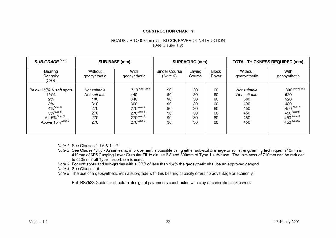
CONSTRUCTION CHART 3
ROADS UP TO 0.25 m.s.a. - BLOCK PAVER CONSTRUCTION (See Clause 1.9)
SUB-GRADE Note 1 SUB-BASE (mm) SURFACING (mm)
TOTAL THICKNESS REQUIRED (mm)
Bearing Capacity (CBR)
Without geosynthetic
With geosynthetic
Binder Course (Note 5)
Laying Course
Block Paver
Without geosynthetic
With geosynthetic
Below 1½% & soft spots
1½% 2% 3%
4%Note 5
5%Note 5
6-15%Note 5
Above 15%Note 5
Not suitable Not suitable
400 310 270 270 270 270
710Notes 2&3
440
340
300
270Note 5
270Note 5
270Note 5
270Note 5
90 90 90 90 90 90 90 90
30 30 30 30 30 30 30 30
60 60 60 60 60 60 60 60
Not suitable Not suitable
580 490 450 450 450 450
890 Notes 2&3
620
520 480
450 Note 5
450 Note 5
450 Note 5
450 Note 5
Note 1 See Clauses 1.1.6 & 1.1.7 Note 2 See Clause 1.1.6 - Assumes no improvement is possible using either sub-soil drainage or soil strengthening technique. 710mm is
410mm of 6F5 Capping Layer Granular Fill to clause 6.8 and 300mm of Type 1 sub-base. The thickness of 710mm can be reduced to 620mm if all Type 1 sub-base is used.
Note 3 For soft spots and sub-grades with a CBR of less than 1½% the geosythetic shall be an approved geogrid. Note 4 See Clause 1.9 Note 5 The use of a geosynthetic with a sub-grade with this bearing capacity offers no advantage or economy. Ref: BS7533 Guide for structural design of pavements constructed with clay or concrete block pavers.

Version 1.0 1 February 2005 23
CONSTRUCTION CHART 4
ROADS UP TO 2.0 m.s.a. - NORMAL FLEXIBLE CONSTRUCTION
SUB-GRADE Note 1 SUB-BASE (mm) SURFACING (mm)
TOTAL THICKNESS REQUIRED (mm)
Bearing Capacity (CBR)
Without geosynthetic
With geosynthetic
Binder Course
Surface Course
Without geosynthetic
With geosynthetic
Below 1½% & soft spots 1½% 2% 3%
4%Note 6
5%Note 6
6-15%Note 6
Above 15%Note 6
Not suitable Not suitable
400 310 260 230 230 230
710 Notes 2&3 440 340 300
260Note6
230Note 6
230Note 6
230Note 6
Note 4
180 180 180 180 180 180 180 180
40 40 40 40 40 40 40 40
Not suitable Not suitable
620 Note 5
530 Note 5
480 Note 5
450 Note 5
450 Note 5 450 Note 5
930Notes 2 & 5 660 Note 5
560 Note 5
520 Note 5
480 Notes 5 & 6
450 Notes 5 & 6
450 Notes 5 & 6
450 Notes 5 & 6
Note 1 See Clauses 1.1.6 & 1.1.7 Note 2 See Clause 1.1.6 - Assumes no improvement is possible using either sub-soil drainage or soil strengthening technique. 710mm is
410mm of 6F5 Capping Layer Granular Fill to clause 6.8 and 300mm of Type 1 sub-base. The thickness of 710mm can be reduced to 620mm if all Type 1 sub-base is used.
Note 3 For soft spots and sub-grades with a CBR of less than 1½% the geosythetic shall be an approved geogrid. Note 4 Initial Binder Course layer thickness 110mm if the alternative kerbing installation method (two stage construction – kerbing to be
laid at a later stage) is used. This may be laid in one layer. The total thickness of Binder Course becomes 190mm in these circumstances. See Clause 1.1.17.
Note 5 Total thickness increased by 10mm above these values if the alternative kerbing installation method is used. See Clause 1.1.17. Note 6 The use of a geosynthetic with a sub-grade with this bearing capacity offers no advantage or economy.

Version 1.0 1 February 2005 24
CONSTRUCTION CHART 5
ROADS UP TO 2.0 m.s.a. - MINIMUM DEPTH FLEXIBLE CONSTRUCTION (See Clause 1.1.18)
SUB-GRADE Note 1 SUB-BASE (mm) SURFACING (mm) TOTAL THICKNESS REQUIRED (mm)
Bearing Capacity
(CBR)
Non-frost susceptible
Type 1
Binder Course
Surface Course
When sub-grade is classified as
frost susceptible
Below 1½% & soft spots 1½% 2% 3% 4% 5%
6-15% Above 15%
Note 2 Note 2
150 150 150 150 150 150
Note 3
260 260 260 230 220 210 200 200
40 40 40 40 40 40 40 40
Note 2 Note 2
450 Note 4
420 Note 4
410 Note 4
400 Note 4
390 Note 4
390 Note 4
Note 1 See Clauses 1.1.6 & 1.1.7 Note 2 See Clause 1.1.6 Requires at least 150mm Type 1 Sub-Base plus an approved sub-soil improvement technique
Note 3 Initial Binder Course layer thickness 110mm if the alternative kerbing installation method (two stage construction – kerbing to be laid at a later stage) is used. This may be laid in one layer.
The total thickness of Binder Course is increased by 10mm in these circumstances. See Clause 1.1.17. Note 4 Total thickness increased by 10mm above these values if the alternative kerbing installation method is used. See Clause 1.1.17.

Version 1.0 1 February 2005 25
CONSTRUCTION CHART 6
ROADS UP TO 2.0 m.s.a. - BLOCK PAVER CONSTRUCTION
SUB-GRADE Note 1 SUB-BASE (mm) SURFACING (mm)
TOTAL THICKNESS REQUIRED (mm)
Bearing Capacity (CBR)
Without geosynthetic
With geosynthetic
Binder Course
Laying Course
Block Paver
Without geosynthetic
With geosynthetic
Below 1½% & soft spots
1½% 2% 3%
4%Note 4
5%Note 4
6-15%Note 4
Above 15%Note 4
Not Suitable Not Suitable
400 310 260 225 220 220
710 Note 2
440
340 300
260Note4
225Note 4
220Note 4
220Note 4
120 120 120 120 120 120 120 120
30 30 30 30 30 30 30 30
80 80 80 80 80 80 80 80
Not Suitable Not Suitable
630 540 490 455 450 450
940 Notes 2 & 3
670
570 530
490 Note 4
455 Note 4
450 Note 4
450 Note 4
Note 1 See Clauses 1.1.6 & 1.1.7 Note 2 See Clause 1.1.6 - Assumes no improvement is possible using either sub-soil drainage or soil strengthening technique. 710mm is
410mm of 6F5 Capping Layer Granular Fill to clause 6.8 and 300mm of Type 1 sub-base. The thickness of 710mm can be reduced to 620mm if all Type 1 sub-base is used.
Note 3 For soft spots and sub-grades with a CBR of less than 1½% the geosythetic shall be an approved geogrid. Note 4 The use of a geosynthetic with a sub-grade with this bearing capacity offers no advantage or economy. Ref: BS7533 Guide for structural design of pavements constructed with clay or concrete block pavers.

TYPICAL SECTION THROUGHCARRIAGEWAY EDGE ANDFOOTWAY EDGE
2
50 x 150 Precast concrete edging
2.1 CHARTS 1,2,4,& 5 Type Roads
75
330ST3
Concrete
120
30
250 x 125 Precast concrete kerb
ST3Concrete
110
Mortar (30mm)
100150150
100
150
100
2.2 CHART 3 & 6
75
330ST3
Concrete
120
30
50 x 150 Precast concrete edgingSmall Kerb Unit
ST3Concrete
Mortar (30mm)100
150
150
2 Rows laid in stretcher bond
Blocks laid in herringbone bond
FOR CARRIAGEWAY AND FOOTWAY DETAILS SEE SECTION 1 CHARTS 1 TO 6
5050
150
26
100

2.3 SHARED SURFACE ROAD PLAN
27
RAMP
1.8m
900m
m W
IDE
AC
CES
S TO
DW
ELLI
NG
VEHICLEACCESS
PED.ACCESS
1.8m
SERVICESTRIP
1.8m
SERVICESTRIP
MA
XIM
UM
GR
AD
IEN
TTO
WA
RDS
CA
RR
IAG
EWA
Y 1:
12
1:25 GR
AD
IENTTO
WA
RDS
CA
RR
IAG
EWAY
GR
ASS
GR
ASS
700m
m
1.8m
1.8mFOOTWAY
1.8mFOOTWAY
110mmKERB FACE
FLUSHKERB FACE
2 No. ROAD HUMPMARKINGS TO DIAG.1062
25mm KERBFACE
SHARED ROADSURFACE
25mm KERBFACE
EDGINGS
EDGINGS
MA
XIM
UM
GR
AD
IEN
TTO
WA
RDS
CA
RR
IAG
EWA
Y 1:
12
EDGE OF HIGHWAY TOBE SUITABLY MARKED
(EDGINGS ORMARKERS AS SGREED)
NO TACTILE PAVINGREQUIRED
KEY
AREA TO BE BLOCK PAVED
AS MAIN FOOTWAYCONSTRUCTION
NOTES:
1. DIAG.557.1 ROAD SIGN TO BEERECTED PRIOR TO RAMP.
2. TACTILE PAVING SHOULD NOT BEUSED ON SHARED SURFACE ROAD.
A
A

2.4 SHARED SURFACE ROAD SECTION
28
DES
IGNE
D V
ERTI
CAL
ALIG
NMEN
TD
ESIG
NED
VER
TICA
LAL
IGNM
ENT
TOP
OF
KERB
Y =
1 No
. 1/2
4 G
RADE
DRO
PPER
KER
B
85mm
25mm
25mm
YY
END
OF
FOO
TWA
Y
110mm
700m
m
110mm
900m
m P
EDES
TRIA
NA
CC
ESS
TO D
WEL
LING
VEH
ICU
LAR
AC
CESS

2.5 CHANNEL BLOCK AND KERB DETAIL
250 x 125 Precast concrete kerb
ST3Concrete
110
Mortar
100150150
100
150
100
2.6 Service Margin Detail -Shared Surface
250 x 125 Precast channel block
Minimum 100 topsoil and t hen turved
100 x 100 x 900 Concrete markerpost to denote highway boundary.Maximum Spacing 5.0 metresTo be installed prior to occupancy ofdwellings
Minimum 1800
29

Chart 1 Type Road Utilising Alternative Method OfKerb Installation (Two stage construction; kerbing tobe added at a later stage)
2.7
FOR CARRIAGEWAY AND FOOTWAY DETAILS SEE SECTION 1 CHARTS 1 TO 6
30
ST3Concrete
150150
150
50 x 150 Precast concrete edging
75
330ST3
Concrete
120
30
250 x 125 Precast concrete kerb
ST3Concrete
110
Mortar (30mm)
100150150
100
150
100
70m
m
Initial Binder Course
Binder course laid 50mmwider to allow for futuretrimming to accept kerbs
STAGE 1
Kerb bed/race laid to assistlevel control
STAGE 2
40mm Surface Course60mm Binder courseLaid at a later stage
70m
m
Initial Bindercourse
Binder course saw cut backto accept kerbs (Infillmaterial to be approved)

Version 1.0 1 February 2005 31
3. TRAFFIC AND SAFETY MEASURES DURING CONSTRUCTION 3.1 TEMPORARY TRAFFIC SIGNS The Developer shall erect and maintain on the site and on the approaches to the site all traffic
signs and traffic control signals necessary for the direction and control of traffic. The signs shall conform to the current Traffic Signs Manual Chapter 8 “Traffic Safety Measures and Signs for Roadworks and Temporary Situations 1991” (published by TSO). The signs shall be reflectorised and kept clean and legible.
3.2 CONTROL OF TRAFFIC If, during any part of the construction, it becomes necessary to restrict or interfere with the flow of
traffic on the public highway, then approval must be obtained from the Highway Authority. A minimum of two week’s notice will be required for such approval.
Where traffic signals are required, a minimum of two week’s notice is also required from the
Divisional Highways Manager as above. For Trunk Roads this notice is extended to six weeks and approval is required from the Highways Agency’s Trunk Road Agent.
Three or four-way temporary signals will require separate approval by the Traffic Signals Engineer. 3.3 TEMPORARY DIVERSION OF TRAFFIC The Developer shall construct temporary diversion ways wherever the works will interfere with
existing public or private roads or other ways over which there is a public or private right of way for any traffic. Any diversion shall be suitable in all respects for the type and volume of traffic requiring to use it. It shall be constructed in advance of taking up the existing way and regularly maintained.
3.4 SAFETY CODES The Developer shall comply with the current Traffic Signs Manual Chapter 8 “Traffic Safety
Measures and Signs for Roadworks and Temporary Situations” 1991 (published by TSO) and all of the relevant current safety standards.
3.5 EXCAVATIONS The Developer shall ensure that all excavations on the site and on the approaches to the site are
adequately signed, fenced and supported. 3.6 MATERIALS ON THE HIGHWAY No building materials etc. shall be stored on the public highway, without the permission of the
Highway Authority. Care should also be taken not to impede visibility at junctions through the inappropriate storage of materials on site.

Version 1.0 1 February 2005 32
3.7 MUD, ETC., ON THE HIGHWAY Developers are reminded that under the Highways Act 1980, they are responsible for ensuring that the existing public highway is kept clear from mud, stones, silt, etc. at all times. Every effort should also be made to keep sites, where dwellings are occupied, in a safe and tidy condition.

Version 1.0 1 February 2005 33
4. SITE CLEARANCE 4.1 CLEARING SITE Trees, stumps and tree roots within the proposed highway shall be removed. Holes left by the
demolition of buildings, by uprooting trees etc., shall be filled in accordance with Clause 5.6.

Version 1.0 1 February 2005 34
5. DRAINAGE 5.1 GENERAL PRINCIPLES 5.1.1 The normal process for the drainage of developments is that the Developer enters into an
agreement with the appropriate sewerage undertaker under Section 104 of the Water Industry Act 1991 for the design and construction of the foul and surface water sewers, which are ultimately adopted by the sewerage undertaker as public sewers. The Highway Authority in these circumstances normally only adopts the road gullies and the connections to the surface water sewer.
This reflects the consideration that Government funding to Highway Authorities does not
account for additional costs that would be incurred from the adoption of highway only drainage infrastructure. Also, it is not possible for Highway Authorities to demand ongoing charges (as is the case for sewerage undertakers who charge sewerage rates) from those who benefit from such arrangements.
5.1.2 In view of the above, where the Highway Authority is to adopt certain highway only
drainage infrastructure (other than for gully connections) the developer will be required to pay Commuted Maintenance payments calculated by the Highway Authority. The Highway Authority will not consider for adoption any systems which collect roof, curtilage water or land drainage.
5.1.3 Pumping Stations and rising mains will not be considered for adoption as part of a highway
drainage system.
5.1.4 Sustainable Drainage Systems (SuDS) and above-ground attenuation systems have been proposed as solutions for dealing with surface water flows in environmentally friendly ways; however, the Highway Authority is generally constrained to only accepting pipe systems for adoption. At the time of publishing this specification, definitive design guidance for SuDS and above-ground attenuation systems was not available, and there are uncertainties regarding future ownership and maintenance; as a result, these alternative methods of drainage are outside the scope of this Specification.
5.1.5 Should a developer wish to propose a SuDS or above-ground attenuation system solution to
surface water drainage of a development, they should contact the Highway Authority at an early stage to discuss the likely acceptability of such proposals and any requirements and safeguards which the Highway Authority may wish to be in place. These include:
a) highway drains should have a hydraulically free discharge into any SuDS or above-
ground attenuation device; b) above-ground attenuation devices should have a high level weir at the outlet, set below
the invert level of the incoming highway drain; c) adequate administrative arrangements for the future maintenance of the facility; d) a Deed of Grant of Rights for the Highway Authority to discharge water into the SuDS or
attenuation facility in perpetuity; e) sufficient design capacity to accommodate the requirements of Clauses 5.4.1 to 5.4.8.
5.1.6 Soakaways may be considered for adoption in exceptional circumstances, but only on small sites where there is no positive outfall within reasonable proximity to the site. Due to this and the specialist design and site investigation requirements for soakaways, and the wide variation

Version 1.0 1 February 2005 35
of construction techniques available, they are outside the general scope of this Specification. Should a Developer wish to propose the use of soakaway systems for highway drainage, they should contact both the Highway Authority and Lincs Laboratory at an early stage to discuss the acceptability of the proposal to use soakaways and detailed design requirements.
Soakage tests and designs of highway soakaways shall be in accordance with BRE Digest
365:1991 “Soakaway Design” Soakaways should be located within an area to be adopted by the Highway Authority. In
exceptional circumstances they may be located within an area of Public Open space that is to be maintained by the District Council, subject of course, to the written approval of the District Council. Soakaways will not be permitted within 5 metres of building foundations, within 2 metres of the carriageway, within 1 metre of any service or area required for services nor within areas of fill. Soakaways will not be permitted beneath the carriageway itself. The Developer’s attention is drawn to the requirements of Building Regulations with regard to the location of soakaways.
5.1.7 Notwithstanding the above, any approved soakaways would need to accommodate the
requirements of Clauses 5.4.1 to 5.4.8.
5.1.8 A “consent to investigate and to discharge” licence may be required by the Environment Agency for soakaways, and where this is the case, a copy of the Agreement must be given to the Highway Authority before approval is given. Details of relevant consents for discharge and wayleave/easements must be submitted to the Highway Authority for consideration before approval is given.
5.2 DESIGN – LAYOUT
5.2.1 Highway drainage systems should, in general, be situated within the area which is to be
adopted by the Highway Authority. The exceptions being that the final outfall pipe run, which may cross other land, subject to the necessary wayleave/easements being provided, and soakaways which in exceptional circumstances may be located within an area of public open space that is to be maintained by the District Council, subject to the written agreement of the District Council.
5.2.2 Manholes and sewers should be sited with due regard to public utility services. A manhole
should be built at every change of alignment or gradient; at the head of all pipe runs; at every junction of two or more pipes (other than gully connections); wherever there is a change in the size of the pipe. Manholes should not be further apart than 100m.
5.2.3 When in a highway, the outside of the pipe should be in the vehicle carriageway (not footway)
and be at least 1m from the kerb line. The outside of manholes should be at least 0.5m from the kerb line.
5.2.4 Buildings should be located at least 3m away from highway drains where the depth from
ground level to invert is less than 3m. In circumstances of large diameter drains, greater depth, unusual ground profile or material, the Highway Authority may require a greater distance.
5.2.5 Highway drains laid within highways should have a minimum cover of 1.2m measured from the
top of the pipe barrel to the finished road surface, in order to avoid interference with other underground utility pipes and cables. Where this is not practicable, special protective measures in accordance with Clause 5.13.4 will be required. The design of the pipeline should take account of loading from the passage of the Developer’s construction plant, as well as normal design loading. Highway drains not laid in the highway should be laid at a sufficient depth to avoid interference with land drains or cultivation. Cover over the shallowest part of the pipeline structure of 0.9m would normally satisfy this requirement.

Version 1.0 1 February 2005 36
5.2.6 The minimum size of highway drains to be adopted is 150mm nominal internal diameter.
5.2.7 Details of headwalls for highway drain outfalls, shall be submitted for approval by the Highway
Authority.
5.3 CONNECTIONS TO EXISTING DRAINS OR PUBLIC SEWERS
5.3.1 Before entering or breaking into an existing sewer or drain, the Developer must obtain the permission of the Authority responsible for the pipeline to which the connection is to be made. Where excavation within the existing public highway is necessary, the permission of the Highway Authority must be obtained and a permit to work in the highway under the New Roads and Streetworks Act must be obtained from the Highway Authority.
5.3.2 Should a developer wish to drain any part of a proposed development to an existing highway
drainage system, the developer will be required to submit a full survey of the existing system together with calculations in accordance with clauses 5.4.1 to 5.4.8 to demonstrate its suitability to accept additional flows. Should it become necessary to improve the existing highway drainage system within the existing public highway a separate agreement will be required under Section 278 of the Highways Act 1980.
5.3.3 The Developer should be aware that particular conditions may be imposed for connections to
brick sewers, large diameter sewers or where adverse conditions make construction of a manhole difficult. The Undertaker or Highway Authority may elect to make the connection at the Developer’s expense. This should be taken into account when designing the system.
5.3.4 In general, the connection into an existing highway drainage system will require the
construction of a new manhole.
5.3.5 Notice needs to be taken of the Undertaker’s or Highway Authority’s health and safety procedures for working in public sewers or existing highway drainage systems, or existing highway drainage systems.
5.4 HYDRAULIC DESIGN
5.4.1 An appropriate flow simulation method based on the Wallingford Procedure should be used for
hydraulic design unless otherwise agreed with the Highway Authority, e.g. in the case of small developments. Calculations must be submitted for approval by the Highway Authority in an intelligible format acceptable to the Highway Authority.
5.4.2 The system should be designed under pipe full conditions to accept the following design
storms (i.e. without surcharging above pipe soffit): Sites with average ground slopes greater than 1% 1 year Sites with average ground slopes 1% or less 2 years Sites where consequences of flooding are severe (e.g. existing basement properties adjacent to new development) 5 years.
5.4.3 The system should be designed for run off from highway areas only, including; roads, footways, access crossings, lay-bys and verges to be adopted by the Highway Authority. For these areas, an impermeability of 100% should generally be assumed. No other areas should drain directly or indirectly to the highway to be adopted.
5.4.4 The minimum velocity should be 1m/sec at pipe full flow.
5.4.5 The roughness value (ks) for surface water design should be 0.6mm.

Version 1.0 1 February 2005 37
5.4.6 The system should be designed not to flood any part of the development in a 1 in 30 year return period design storm.
5.4.7 Spacing of gullies shall be determined on the basis of one gully per 180 square metres of
impervious area to be drained, including footways, access crossings, lay-bys and verges.
5.4.8 During extremely wet weather, the capacity of the system may be inadequate, even though it has been designed in accordance with this Specification. Under such conditions, the system may surcharge and surface water may escape from those manhole covers and gullies which lie below the hydraulic gradient. Checks should be made to ensure that an adequate level of protection against the flooding of properties internally is achieved and the design is adjusted where the required flooding protection is not achieved. This is particularly important on undulating or steeply sloping catchments. In designing the site layout, including building floor levels and site levels, Developers should also demonstrate flow paths and the potential effects of flooding resulting from storm events exceeding the design criteria. Developers should ensure and demonstrate that properties will not, as a minimum, be flooded in a 1 in 100 year return period.
5.5 PIPES AND COUPLINGS
5.5.1 One type of pipe shall be used within any individual drain length, including connections,
between manholes. All pipes and joints shall be jointed in accordance with the manufacturer’s instructions.
5.5.2 Pipes and fittings for drainage shall be selected from the following:-
Vitrified Clay Pipes and Fittings
5.5.3 Vitrified clay pipes and fittings shall have flexible mechanical joints. Pipes shall comply with the relevant requirements of BS EN 295 and BS 65 (surface water pipes only).
Concrete Pipes and Fittings
5.5.4 Unreinforced and reinforced concrete pipes and fittings with flexible joints shall comply with the relevant provisions of BS 5911: Part 100 and 110, respectively.
5.5.5 All pipes and fittings shall have gasket-type joints of spigot and socket or rebated form, unless
otherwise agreed with the Highway Authority.
5.5.6 Particular requirements from the options listed in Appendix A of BS 5911: Part 100 should be shown on the Drawings.
Unplasticised PVC Pipes and Fittings
5.5.7 Unplasticised PVC pipes, joints and fittings shall comply with the relevant provisions of BS 4660: 2000 and BS EN 1401-1.
5.5.8 Structured wall unplasticised PVC sewer pipe shall comply with the relevant provision of WIS
4-35-01. 5.5.9 Solvent cements for jointing unplasticised PVC pipes shall comply with the relevant revisions of
BS 4346: Part 3 and BS EN 1401-1. For pipes and fittings complying with BS 4660:2000, solvent cement may alternatively comply with BS 6209.
5.5.10 BS EN 1295-1 gives guidance on the structured design of underground non-pressure PVC-U pipes.

Version 1.0 1 February 2005 38
Flexible Couplings 5.5.11 Flexible couplings shall comply with the provisions of WIS 4-41-01 and BS EN 295-4. 5.6 MANHOLES 5.6.1 Figures 5/1 to 5/4 show typical details of manholes with depths from cover level to soffit of pipe
not exceeding 6m. No significant departure from these should be made without approval by the Highway Authority. However, in special circumstances where there is a significant risk of high levels of detritus entering the drainage system catchpit manholes may be specified by the Highway Authority. Manholes should be designed and constructed in accordance with BS EN 752-3.
5.6.2 Manhole diameters (Type A and B only) should be in accordance with Table 5/1 below: Table 5/1
Diameter of largest pipe in manhole (mm)
Internal diameter of manhole (mm)
Less than 375
375-450
500 – 700
750 – 900
Greater than 900
1200 (1050 where depth to soffit is 1.35 m – 1.5m)
1350
1500
1800
Consult Highway Authority
5.6.3 The height of a Type A manhole (benching to slab soffit) should normally be in excess of
2000mm. When this is impracticable, Type B manholes are preferred subject to an absolute minimum height (benching to slab soffit) of 900mm.
5.6.4 The internal diameters quoted above are considered to be the minimum. Where two or more
pipes enter the manhole, the internal diameter may have to be increased to accommodate the minimum width of benching. Pipes of different diameters entering manholes should be installed with soffits at the same level.
5.6.5 The dimensions of Types C and D manholes should be as shown on Figures 5/3 and 5/4. Precast Concrete Manholes 5.6.6 Precast concrete manhole units of circular cross-section for manholes shall comply with the
relevant provisions of BS 5911: Part 200. Units which bed into bases shall be manufactured so that imposed vertical loads are transmitted directly via the full wall thickness of the unit. For joints between units and the underside of slabs, joint profiles shall be capable of withstanding applied loadings from such slabs, and spigot-ended sections shall only be used where the soffit of the slab is recessed to receive them.
5.6.7 Particular requirements from the options listed in Appendix A of BS 5911 Part 200 should be
shown on the Drawings.
5.6.8 Precast concrete sections for manholes shall be constructed with steps and slab, rungs aligned correctly.

Version 1.0 1 February 2005 39
5.6.9 The jointing material for precast units shall be mortar or a proprietary bitumen or resin mastic
sealant, with the concrete surfaces prepared in accordance with the manufacturer’s recommendations.
5.6.10 Joints shall be made so that the required jointing material fills the joint cavity. Any surplus
jointing material which is extruded inside the manhole shall be trimmed off and joints shall be pointed on completion.
5.6.11 Concrete surrounds to manholes, chambers and the wet wells shall be C16/20 and the height
of each concrete pour shall not exceed 2m. Each construction joint shall break joint with the precast sections by at least 150mm.
Step Rungs 5.6.12 Step rungs in accordance with EN 13101-1 shall be provided in all manholes (except Type D)
at 300mm intervals. They shall be of galvanised mild steel or plastic encapsulated type. High Strength Concrete Topping to Inverts and Benchings 5.6.13 Inverts and benchings in manholes shall have a screeded ridged finish and shall have a
smooth, high strength concrete topping applied with a steel trowel before the concrete has set. 5.6.14 High strength concrete topping shall be produced, laid and finished in accordance with the
relevant provisions of BS 8204-2 and the following approximate mix proportions by weight shall be used: one part cement, one part natural sand and two parts single sized coarse aggregate.
5.6.15 Aggregates for high strength concrete topping (granolithic finish) shall comply with BS EN
12620, D=10mm, graded in accordance with Table 2 of that Standard. Rocker Pipes 5.6.16 A flexible joint shall be provided as close as is feasible to the outside face of any manhole into
which a pipe is built. The design of the joints shall be compatible with any subsequent movement.
5.6.17 The recommended length of the next pipe (rocker pipe) away from the manhole should be as
shown in Table 5/2 below: Table 5/2
Nominal Diameter (mm)
Effective Length (m)
150 to 600
675 to 750
Over 750
0.6
1.0
1.25
Stub pipes into manholes shall be of rigid material.

FIGURE 5/1TYPICAL MANHOLE DETAIL - TYPE A
Depth from cover level to soffit of pipe 3m to 6m
40
Joint to be as close as possible toface of manhole to permit satisfactoryjoint and subsequent movement
Minimum width of benchingfor loading area to be 500mm
Rocker pipe
Minimum width ofbenching to be 225mm
Pipe joint with channel tobe located minimum100mm inside face ofmanhole
225mm to barrel of pipeInvert to be formed usingchannel pieces
Self cleaning toe holes to beprovided where channelexceeds 600mm wide
High strength concrete topping to bebrought up to a dense smooth faceneatly shaped and finished to all branchconnections (min thickness 20mm)
Lifting eyes in concrete ringsto be pointed
Step irungs to be provided at300mm intervals
All in situ concrete to be C16/20with sulphate resisting cementunless agreed otherwise
On manholes less than 1.5mdiameter reducing slabs not to beused and PC concrete rings tocontinue up to cover slab
Minimum clear access600mm Shaft diameter 675mm
Mortar haunching to coverand frame
Cover and frame to bebedded on mortar
Precast concrete manhole sectionsand cover slab to be bedded withmortar,proprietory bitumen or resinmastic sealant
Concrete surround 150mmthick
The bottom precast section tobe built into base concreteminimum 75mm
Benching slope to be 1 in 10to 1 in 30
Distance between top of pipeand underside of precastsection to be 50mm
Class B engineering bricks,concrete blocks or precast concretecover frame and sealing rings

FIGURE 5/2TYPICAL MANHOLE DETAIL - TYPE B
Depth from cover level to soffit of pipe up to 3m
41
Joint to be as close as possible toface of manhole to permit satisfactoryjoint and subsequent movement
Minimum width of benchingfor loading area to be 500mm
Rocker pipe
Minimum width ofbenching to be 225mm
225mm to barrel of pipeInvert to be formed usingchannel pieces
Construction joint
High strength concrete topping to bebrought up to a dense smooth faceneatly shaped and finished to all branchconnections (min thickness 20mm)
Lifting eyes in concrete ringsto be pointed
Step irungs to be provided at300mm intervals
All in situ concrete to be C16/20with sulphate resisting cementunless agreed otherwise
Class B engineering bricks,concrete blocks or precast concretecover frame and sealing rings
Minimum clear access600mm
Mortar haunching to coverand frame
Cover and frame to bebedded on mortar
Precast concrete manholesections and cover slab to bebedded with mortar,proprietorybitumen or resin mastic sealant
Concrete surround 150mmthick
The bottom precast section tobe built into base concreteminimum 75mm
Benching slope to be 1 in 10to 1 in 30
Distance between top of pipeand underside of precastsection to be 50mm
Chamber height not less than900mm
Invert to be formed usingchannel pieces
Self cleaning toe holes to beprovided where channelexceeds 600mm wide

FIGURE 5/3TYPICAL MANHOLE DETAIL - TYPE C
Depth from cover level to soffit of pipe 1.0m to 1.5m
42
Rocker pipe
Invert to be formed usingchannel pieces
All in situ concrete to be C16/20 withsulphate resisting cement unlessagreed otherwise
Joint to be as close as possible toface of manhole to permitsatisfactory joint and subsequentmovement
1240mm
675m
m
Pipe joint with channel to belocated inside face of manhole
675
Arch over pipe
Mortar haunching tocover and frame
Class B engineeringbricks, concrete blocksnot less than 200mm thick
Benching slope to be1 in 10 to 1 in 30
225mm to barrel of pipe
High strength concretetopping minimumthickness 20mm
Internal dimensions of manhole normally1240mm x 675mm but manhole widths shouldbe increased for pipes larger than 225nndiameter to give 225 benching each side andthe brickwork / masonry units corbelled down tosuit cover
150mm minimum
1220mm x 685mm multiple ductile ironcover on mortar bedding
Class B engineering bricks, concreteblocks to be corbelled to suit cover
Step rungs to beprovided at 300mmintervals
150mm minimum

FIGURE 5/4TYPICAL MANHOLE DETAIL - TYPE D
Depth from cover level to soffit of pipe less than 1.0m
43
Rocker pipe
Invert to be formed usingchannel pieces
All in situ concrete to be C16/20 withsulphate resisting cement unlessagreed otherwise
Joint to be as close as possible toface of manhole to permitsatisfactory joint and subsequentmovement
900mm
675m
m
Pipe joint with channel to belocated inside face of manhole
675
Arch over pipe
Mortar haunching to coverand frame
Class B engineering bricks,concrete blocks not lessthan 200mm thick
Benching slope to be 1 in10 to 1 in 30
225mm to barrel of pipe
High strength concretetopping minimumthickness 20mm
Internal dimensions of manhole normally1240mm x 675mm but manhole widths shouldbe increased for pipes larger than 225nndiameter to give 225 benching each side andthe brickwork / masonry units corbelled down tosuit cover
150mm minimum
900mm x 600mm cover bedded onmortar
Class B engineering bricks, concreteblocks to be corbelled to suit cover
900mm
Arch over pipe
The use of precast rectangular concrete manhole units with 150mm C16/20concrete surround is permitted. The concrete to be made with sulphate resisting
cement unless otherwise agreed.

Version 1.0 1 February 2005 44
5.7 GULLIES AND CONNECTIONS
5.7.1 All gullies shall be trapped. 5.7.2 Gullies shall be precast concrete, vitrified clay or synthetic materials (see figure 5/5 -Typical
Gulley Details). 5.7.3 Precast concrete gullies shall be unreinforced and comply with the requirements of BS5911-2. 5.7.4 Salt glazed ware gullies shall comply with the requirements for round gullies as specified in
BS65. 5.7.5 Synthetic gullies shall be of approved plastic materials as recommended in CP312 and from
an approved manufacturer. 5.7.6 Gullies shall be at least 750mm deep by 450mm diameter with 150mm outlet, trapped and
with stoppered rodding eye and chain. 5.7.7 Footway gullies shall be rectangular salt-glazed ware or precast concrete to the approval of
the Highway Authority. The gullies shall be 250mm square and 475mm deep, internal dimensions, and have a 150mm diameter outlet unless otherwise agreed with the Highway Authority.
5.7.8 Gullies shall be laid on and surrounded with 150mm thickness of C12/15 concrete to clause
12.1 made with sulphate resisting cement unless agreed otherwise. 5.7.9 Junction pipes for gullies which are laid but not immediately connected to gullies shall be
fitted with temporary plastic stoppers or seals and the position of all such junctions shall be clearly defined by means of stakes or tracing wires, properly marked and labelled.

Figure 5.5TYPICAL GULLEY DETAILS
150 150 450 150
C16/20 Concrete 150mmthick
Varie
s
Mortar Bed
Mortar Bed
150
150 510 150
Varie
s
TYPE G5TRAPPED ROAD GULLEY
TYPE G7TRAPPED PLASTICROAD GULLEY
30
44
PRECAST CONCRETE AND PLASTIC GULLIES
45
NOT TO SCALE
NOTES:-
1) Cover and frame uncoated iron toClause 5.9.4.
2) Mortar bed and benching to Clause 15.
3) Bricks to be Class B engineeringbricks to BS3921 (single course wherenecessary to obtain satisfactory fall.Corbelled if required. Framesto be bricked on all four sides.
4) All in situ concrete to be C16/20 withsulphate resisting cement unless agreedotherwise.
5) Position of outlet pipe varies in plan.
6) In situ C16/20 concrete 150mm thicksurround to outlet pipe for first onemetre underverge or total length if undercarriageway.
7) Where grating is to be trafficked orlaid againstwithin 24 hours of frame being placed inposition,then a suitable Ultra rapid hardeningmortar and concrete (Monoset 241 orsimilar) shall be usedto bed cover and frame.
C16/20 Concrete 150mmthick
794
610
Appr
ox
840
550
Appr
ox
Concrete protection tospecification clause 5.13.4 to
outlet pipe for first 100mmunder verge or total length if
under carriageway

Version 1.0 1 February 2005 46
5.8 BRICKWORK AND BLOCKWORK 5.8.1 Concrete bricks or blocks to be used in manholes, gullies and chambers shall be precast
concrete masonry units manufactured in accordance with BS 6073 containing a minimum of 360 kg/m3 of sulphate resisting cement, having a maximum water/cement ratio of 0.45, a minimum compressive strength of 50 N/mm2, and a maximum water absorption of 7%.
5.8.2 Clay bricks to be used in manholes, gullies and chambers shall be Class B Engineering
complying with the relevant provisions of BS 3921. 5.8.3 The shapes and dimensions of special bricks shall comply with the relevant provisions of BS
4729. All bricks shall be category F. 5.8.4 Brickwork and blockwork construction shall be in accordance with the relevant provisions of
BS 5628-3. 5.8.5 Brickwork and blockwork shall be built in English bond. Bricks and blocks shall be set in
mortar with all bed and vertical joints filled solid; exposed work shall be flush pointed as the work proceeds. The moisture content of the bricks and blocks shall be adjusted so that excessive suction is not exerted on the mortar.
5.8.6 Bricks and blocks in each course shall break joint correctly with the bricks/blocks underneath.
The courses shall be laid parallel, with joints of uniform thickness, and shall be kept straight or regularly curved as required. Brickwork and blockwork shall be gauged to rise 300mm in four courses. Vertical joints shall be in alignment as required by the bond and shall have an average thickness of 10mm. Bricks and blocks forming reveals and internal and external angles shall be selected for squareness and built plumb.
5.8.7 Brickwork and blockwork shall rise uniformly; corners and other advanced work shall be
racked back and not raised above the general level more than 1m. No brickwork or blockwork shall be carried up higher than 1.5m in one day. No bats or broken bricks or blocks shall be incorporated in the work unless essential for bond.
5.8.8 Oversail corbelling shall not exceed 30mm on each course. 5.8.9 Materials used in bricklaying and block-laying shall be frost-free, and no bricks or blocks shall
be laid when the ambient temperature is below 3°C, unless special precautions are taken. Completed work shall be protected adequately during cold weather.
5.9 COVERS AND FRAMES 5.9.1 Manhole and gully covers and frames shall comply with the relevant provisions of BS EN 124
and shall be cast iron or ductile iron. 5.9.2 Manhole covers and frames shall be of a non-rocking design which does not rely on the use
of cushion inserts. 5.9.3 Class D 400 covers and frames shall be used in carriageway and shared surface areas. 5.9.4 Class C 250 covers and frames shall be used in footways, pedestrian areas, verges and
comparable locations. 5.9.5 Gully covers shall be hinged, but not removable, and shall have a nominal clear opening
width of 450mm and a minimum area of waterway of at least 900cm2 for carriageways, and a clear opening of at least 300mm x 300mm for footways. The upper surface of gully gratings shall be flat and slots in gratings or between gratings and frames shall not be orientated parallel to the direction of traffic except where the slots are less than 150mm long or less than 20mm wide. Where gradients are steeper than 1 in 50, storm pattern grids shall be provided.
5.9.6 Manhole covers and frames shall be manufactured in cast iron or ductile iron and shall
comply with the requirements of BS EN 124 and shall be kitemarked or equivalent. (Equivalence with the kitemark will be considered to exist if:-

Version 1.0 1 February 2005 47
The product has been manufactured within an ISO 9000 system that has been assessed by a BS EN 45012 accredited body.
Product testing has been conducted by a body accredited to BS EN 45001 for the testing of manhole tops and gully tops to BS EN 124.
Product conformity certificates shall be from certification bodies accredited to BS EN 45011 for the issuing of certificates to BS EN 124 and shall be awarded to the product manufacturer)
The following markings must appear on all covers and frames: (i) The mark of the certification body. (ii) The manufacturer’s name in full. (iii) The EN class. 5.9.7 Manhole and gully frames shall be set to level, bedded and haunched externally over the
base and sides of the frame in mortar in accordance with the manufacturer’s instructions. The frame shall be seated on at least two courses of Class B engineering bricks, or on precast concrete masonry units or on precast concrete cover frame seating rings to regulate the distance between the tope of the cover and the top rung to no greater than 675mm. A mortar fillet shall be provided where the corners to an opening in a slab are chamfered and the brickwork is not flush with the edges of the opening.
5.10 EXCAVATION FOR DRAINAGE WORKS 5.10.1 The Developer shall carry out his operations in such a manner as to avoid damage to, or
deterioration of, the formation of excavations. 5.10.2 Soft spots shall be removed from the bottom of trenches and other excavations, which shall
then be refilled to formation level with the same material as the permanent work which is to rest on that formation. Any void which results from over-excavation below formation level shall be refilled in the same manner.
5.10.3 Trenches shall be excavated so that the effective width is maintained within any limit imposed
by the design of the pipelines. 5.10.4 Trenches, manholes and all excavations shall be adequately supported at all times and,
where directed or required, the supports shall be left in trenches or excavations. 5.10.5 The Developer shall not allow water to accumulate in any part of the works. Water arising
from or draining into the works shall be drained or pumped to a consented disposal point. Any drainage sumps required shall, where practicable, be sited outside the area excavated for the permanent works, and shall be refilled with Type 1 sub-base material or ST1 concrete to the level of the underside of the adjacent permanent works.
5.10.6 The Developer shall take all necessary precautions to prevent any adjacent ground from
being adversely affected by loss of fines through any dewatering process. 5.10.7 Discharges to sewers or existing highway drainage system shall not take place without the
consent of the relevant Undertaker or Highway Authority. 5.11 BACKFILLING OF TRENCHES AND FILTER DRAINS 5.11.1 Subject to the requirements of Clause 5.14.1, backfilling shall, wherever practicable, be
undertaken immediately the specified operations preceding it have been completed. Backfilling shall not, however, be commenced until the works to be covered have achieved a strength sufficient to withstand all loading imposed thereon.
5.11.2 Backfilling around manholes and gullies shall be undertaken in such a manner as to avoid
uneven loading or damage.

Version 1.0 1 February 2005 48
5.11.3 Excavations not situated beneath the carriageway or footway shall be refilled with approved
and suitable excavation material as defined and classified by the Specification for Highway Works. All filling shall be deposited and compacted in layers, not exceeding 150mm loose depth, to a density not less than 95% of the maximum dry density for that particular filling, as determined by the light hammer test BS1377: Part 4: Tests 3.3 and 3.4. Trench support systems shall be withdrawn ahead of the layer to be compacted, care being taken to keep the sides of the trenches solid and to fill all the spaces left by the withdrawn trench support systems. The Highway Authority may require the use of sub-base to Clause 8.1 in place of excavated material where trenches are deep or narrow.
5.11.4 All trenches and other excavations beneath or within 1m of carriageways and footways,
including drains in carriageways, footways and vehicle crossings, must be refilled with sub-base as specified in Clause 8.1. It is accepted that due to trench widths, the requirements to use rollers to compact the sub-base in trenches may be inappropriate. In these circumstances, alternative compaction equipment may be used to ensure that the compaction requirements are met.
5.11.5 Filter drains shall be backfilled with Type B filter material which shall consist of natural or
recycled coarse aggregate or recycled concrete aggregate complying with BS EN 13242 and the following:
(i) for Type B, geometrical requirements in accordance with Table 5/3 and BS EN
13242; (ii) a resistance to fragmentation in Category LA50 in accordance with BS EN 13242,
clause 5.2 and Table 9; (iii) a water-soluble sulfate content of less than 1.9 grams of sulfate (as SO3) per litre
when tested in accordance with BS EB 1711-1, clause 10; (iv) volume stability of slags as in Table 5/3; (v) all other requirements in Category NR; (vi) be non-plastic when tested in accordance with BS 1377:Part 2. When recycled coarse aggregate or recycled concrete aggregate is used in accordance with
this Clause, it shall not have more than 1% by mass of foreign materials including wood, plastic and metal when tested by a method approved by the Highways Authority.
Table 5/3 Grading and geometrical requirements for filter drain and soakaway material
Type B Standard BS EN 13242 Size, mm 20/40 Grading and oversize categories GC80-20 Oversize category - Category for tolerances at mid-size sieves
GTNR (no requirement)
Category for maximum fines fNR (no requirement)
Volume stability of blast furnace slags Free from dicalicum silicate and iron disintegration
Volume stability of steel (BOF and EAF) slags
V5
Summary grading requirements Sieve size, mm Percentage by mass passing
80 63 40 20 10
100 98-100 80-99 0-20 0-5

Version 1.0 1 February 2005 49
5.12 PIPELAYING 5.12.1 Where socketed pipes are required to be laid on a granular or sand bed, or directly on a
trench bottom, joint holes shall be formed in the bedding material or formation to ensure that each pipe is uniformly supported throughout the length of its barrel and to enable the joint to be made.
5.12.2 Pipes shall be laid on setting blocks only where a concrete bed or cradle is used. 5.12.3 Where pipes are required to be bedded directly on the trench bottom, the formation shall be
trimmed and levelled to provide even bedding of the pipeline and shall be free from all extraneous matter that may damage the pipe, pipe coating or sleeving.
5.12.4 Pipes and fittings shall be examined for damage and the joint surfaces and components shall
be cleaned immediately before laying. 5.12.5 Suitable measures shall be taken to prevent soil or other material from entering pipes, and to
anchor each pipe to prevent flotation or other movement before the works are complete. 5.12.6 Pipes shall be cut in accordance with the manufacturer’s recommendations. Where
necessary, the cut ends of pipes shall be formed to the tapers and chamfers suitable for the type of joint to be used.
5.12.7 Pipe jointing surfaces and components shall be kept clean and free from extraneous matter
until the joints have been made or assembled. Care should be taken to ensure that there is no ingress of grout or other extraneous material into the joint annulus after the joint has been made.
5.12.8 Where concrete pipes are cut, any exposed reinforcement shall be sealed with an epoxy resin
mortar. 5.12.9 The position of the internal face of any highway drain shall not deviate from the line and level
described in the Agreement or agreed variation by more than ± 20mm, provided that no pipeline shall have a reverse gradient.
5.13 BEDDING, LAYING AND SURROUNDING OF PIPES 5.13.1 Immediately following the excavation of the trench, the pipes shall be laid and jointed on the
pipe bed. Pipes shall be laid so that each one is in contact with the bed throughout the length of its barrel. Brick, concrete setting blocks or other hard material shall not be placed under the pipes for temporary support. In the case of socketed or sleeved jointed pipes, the bed shall be cut away and removed at each socket or sleeve so that the socket or sleeve does not bear on the bed.
5.13.2 Pipe bedding and haunching or surrounding material shall consist of natural and/or recycled
coarse aggregate or recycled concrete aggregate complying with BS EN 13242. Where recycled coarse aggregate or recycled concrete aggregate is used in this Clause it shall not have more than 1% by mass of foreign materials including wood, plastic and metal when tested in accordance with a method approved by the Highway Authority (see Clause 1.1.13) and comply with the requirements in Table 5/3. Pipe bedding, haunching and surrounding material shall comply with the following:
(a) Geometrical requirements in accordance with Table 5/4 or Table 5/5;
(b) A resistance to fragmentation in Category LA50 in accordance with BS EN 13242, clause 5.2 and Table 9;
(c) A water soluble sulfate content of less then 0.19% (as SO3) when tested in
accordance with BS EN 1744-1, clause 10; (d) Blast furnace slags shall be free from discalcium silicate and iron
disintegration;

Version 1.0 1 February 2005 50
(e) The volume stability of steel (BOF and EAF) slags shall be V5; (f) All other requirements in Category
Table 5/4: BS EN 13242, Coarse aggregate for pipe bedding, haunching and surrounding material
Table 5/5: BS EN 13242, Fine and all-in aggregate for pipe bedding, haunching and surrounding material
BS EN 13242, Fine and all-in aggregate (clause 4.3.3) Fine All-in Category for general grading requirements Category GF80 Category GA80 Category for tolerances on manufacturer’s Declared typical grading
GTFNR (no requirement)
GTANR (no requirement)
Category for maximum values of fines content
Gravel –f3 Crushed rock, recycled aggregate – f11
Aggregate size, mm Nominal pipe diameter, mm Fine All-in
Not exceeding 140 0/10 Exceeding 140 but not exceeding 400 0/10 or 0/20 Exceeding 400
0/1, 0/2, 0/4 or 0/6
0/10, 0/20 or 0/40
5.13.3 Bedding for pipes shall be constructed by spreading and compacting granular bedding material over the full width of the pipe trench. After the pipes have been laid, additional granular material shall, if required, be placed and compacted equally on each side of the pipes, and where practicable, this shall be done in sequence with the removal of the trench supports.
5.13.4 All pipes with less than 1.2m of cover, or where in the opinion of the Highway Authority the
nature of the ground demands it, shall be subject to concrete protection as follows.
Pipes to be surrounded with concrete shall be supported on precast concrete setting blocks, the top face of each block being covered with two layers of compressible packing.
Precast concrete setting blocks for pipes shall have rectangular faces, with sufficient plan
area to prevent punching of the blinding concrete or formation and to provide an adequate seating for the pipes. Blocks shall be manufactured from ST4 concrete using the same type of
BS EN 13242, Coarse aggregate (clause 4.3.2) Category for general grading requirements Gc80-20 Category for tolerances at mid-size sieves GTNR (no requirement)
Category for maximum values of fines content
Gravel – f1.5 Crushed rock, recycled aggregate – f4
Aggregate size, mm Nominal pipe diameter, mm Graded Single sized
Not exceeding 140 - 4/10 Exceeding 140 but not exceeding 400 2/14, or 4/20 4/10, 6/14 or 10/20 Exceeding 400 2/14, 4/40 or
4/40 4/10, 6/14, 10/20 or 20/40

Version 1.0 1 February 2005 51
cement as in the adjacent concrete bed, and be cast in an approved mould. Blocks shall not
be used until they have achieved a cube strength of 13.5 N/mm2. Concrete provided as a protection to pipes shall be ST4 placed to the required depth of
150mm above and below the pipe for the full width of the trench in one operation. Where pipes with flexible joints are used, concrete protection shall be interrupted over its full cross-section at each pipe joint by a shaped compressible filler.
Compressible filler for interrupting concrete protection to pipes shall consist of bitumen
impregnated insulating board to BS EN 120 and BS EN 317, or other equally compressible material. The thickness of compressible filter shall be as given in Table 5/6 below:
Table 5/6
Nominal diameter of pipe
(mm) Thickness of compressible
filler (mm) Less than 450
450 – 1200
Exceeding 1200
18
36
54 Compressible packing for use between pipes and precast concrete setting blocks shall
consist of bitumen damp-proof sheeting complying with BS 743.
5.13.5 A further surround about the bed, haunch and surround described above shall be provided to a height of 380mm above the top of the pipe with trench fill material, except there shall not be any stones of lumps of clay >40mm nominal diameter.
5.14 INSPECTION TESTING AND CLEANSING 5.14.1 The Developer shall afford opportunity for the Highway Authority to examine any work which
is about to be covered up or put out of view, and to examine foundations before permanent work is to be placed thereon.
5.14.2 The Developer shall give at least five clear working days’ notice to the Highway Authority
before any formation is covered with permanent work and before testing any pipeline. The Highway Authority will witness all tests to pipelines.
5.14.3 Pipelines shall be tested by the Developer after they are jointed and before any concreting or
backfilling is commenced, other than such as may be necessary for structural stability whilst under test.
5.14.4 A further test shall be carried out after the backfilling is complete. 5.14.5 Pipelines up to and including 750mm nominal diameter shall be tested by means of an air or
water test, and sewers greater than 750mm nominal diameter by a visual examination. This may include a CCTV survey to be provided by the Developer or walk-through inspection.
5.14.6 Pipelines to be air tested shall have air pumped in by a suitable means until a pressure of
100mm head of water is indicated in a U-tube connected to the system. The pipeline shall be accepted if the air pressure remains above 75mm head of water after a period of five minutes without further pumping, following a period for stabilisation. Failure to pass the test shall not preclude acceptance of the pipeline if a successful water test can subsequently be carried out, as follows.
5.14.7 The test pressure shall not be less than 1.2m head of water above the pipe soffit or ground
water level, whichever is the higher, at the highest point, and not greater than 6m head at the lowest point of the section. Steeply graded pipes shall be tested in stages in cases where the maximum head, as stated above, would be exceed if the whole section were tested in one length.

Version 1.0 1 February 2005 52
5.14.8 The pipeline shall be filled with water and a minimum period of two hours shall be allowed for
absorption, after which, water shall be added from a measuring vessel at intervals of five minutes and the quantity required to maintain the original water level noted. Unless otherwise specified, the length of sewer shall be accepted if the quantity of water added over a 30 minute period is less than 0.5 l per linear metre per metre of nominal diameter.
5.14.9 Notwithstanding the satisfactory completion of the above test, if there is any discernible
leakage of water from any pipe or joint, the pipe shall be replaced and/or the joint remade, as appropriate, and the test repeated until leakage is stopped.
5.14.10 Should there be any concerns over the integrity of a pipeline at any stage of the Development,
the Highway Authority may request the Developer to carry out a CCTV survey and provide the Highway Authority with the results for consideration. The survey and reporting shall be in accordance with the specification contained in the Model Contract Document for sewer condition inspection published by the Water Research Centre (WRC).
5.14.11 Pipelines and manholes shall be inspected and tested for infiltration, after backfilling. All
inlets to the system shall be effectively closed, and any residual flow shall be deemed to be infiltration.
5.14.12 The pipeline and manholes shall be accepted as satisfactory if the infiltration, including
infiltration into manholes, in 30 minutes does not exceed 0.5 l per linear metre per metre of nominal bore.
5.14.13 Notwithstanding the satisfactory completion of the above inspection or test, if there is any
discernible flow of water entering the sewers of manholes which can be seen either by visual or CCTV inspection, the Developer shall take such measures as are necessary to stop such infiltration.
5.14.14 On completion of construction, internal surfaces of pipelines, gullies and manholes shall be
thoroughly cleansed to remove all deleterious matter, without such matter being passed forward into existing public sewers, highway drains, or water courses. The pipelines, gullies and manholes shall be maintained in a clean and serviceable condition by the Developer until they are adopted by the Highway Authority.

Version 1.0 1 February 2005 53
6. EARTHWORKS 6.1 FORMATION LEVEL Formation level is the finished level of the existing soil after completion of the earthworks, i.e.
the underside of the sub-base. Any excess depth excavated shall be backfilled with sub-base material in accordance with Clause 8.1.
Within 24 hours of the final preparation of the formation level it shall be covered with a
minimum thickness of 150mm of compacted sub-base in accordance with Clause 8.1. Construction traffic shall not run on the prepared formation.
To prevent problems of weed growth, a suitable weed killer should be applied to the formation
of the footway. 6.2 TOPSOIL Turf and all topsoil shall be removed from the area of the roadworks and stockpiled for re-
use. Topsoil shall mean the top layer of soil which can support vegetation. The depth of topsoil should be initially determined by the ground investigation.
6.3 SOILING, GRASSING AND TURFING Soiling and compacting of the side slopes of cuttings, embankments and verges shall be
carried out to an even surface with a minimum compacted thickness of 100mm of topsoil. All surfaces to be grassed shall, immediately before sowing, be reduced to a fine tilth and all
stones over 20mm diameter and all harmful material shall be removed. Fertilizer from an approved manufacturer, in the following parts - 10 Nitrogen: 15 Potassium: 10 Phosphorous shall be spread in two directions at a total rate of 50gm/m². Grass seed from an approved manufacturer, shall be spread in two directions at a total rate of not less than 1kg to 50m² and shall consist of the following parts:-
30% PRG (Arno, Lloretta, Derby or Fusta) 40% Strong Creeping Red Fescue (Dawson, Ruby, Boreal or Reubina) 10% Highland Browntop Bent 20% Smooth-Stalked Meadowgrass (Parade, Aquila or Glade) Turfing shall be carried out on topsoil using turfs to BS3969, to give a total minimum
thickness of 100mm of topsoil. Turfs shall be clean, strong, well bonded and lightly beaten. They shall be laid diagonally across side slopes. All turves shall be used within one week of cutting during the period 1 April to 31 August or within two weeks of cutting during the remainder of the year; turves not used within these periods shall be regarded as topsoil.
Grassed areas shall be maintained regularly up to and during the 12 month maintenance
period in order to control weed growth and to prevent the grass from exceeding 50mm in height at adoption.
6.4 EMBANKMENTS AND CUTTINGS Where the nature of the works are such that embankments or cuttings are necessary then the
excavation, classification and placement of materials shall be in accordance with the requirements of the Highways Agency’s current Specification for Highway Works. The site investigation shall address such matters as slope stability, settlement and, where necessary, heave. The ground investigation and associated testing will need to be undertaken, to determine if the materials are acceptable and if so, to classify them as either Class1 or Class 2 general fill materials.

Version 1.0 1 February 2005 54
The proposal to use a particular Class 1 or Class 2 material shall include:-
- The proposed material source. - Proposed material classification against the requirements of Clause 601, Table 6/1.
Where acceptable limits are not quoted in the Table, these will have to be determined for the particular source of material and its end use.
- Proposed means of monitoring the material’s suitability as it is delivered to site, included
sampling and testing frequency.
- Proposed method of compaction and type of plant to be used.
- Proposed means of monitoring its placement and in particular its end product compaction.
- Proposed method of assessing the design CBR at sub-formation level, that is on the
placed and compacted fill material, to permit adjustment to the final sub-base design thickness. This design CBR is likely to be different to that determined on the existing sub-grade.
Developers will require the professional services of an experienced Geotechnical Engineer to prepare their documentation. All laboratory testing must be undertaken by an UKAS accredited laboratory.
The cost of all the additional work associated with preparing and undertaking their proposal will be at their expense.
6.5 DISPERSAL OF STANDING WATER The Developer must ensure the rapid dispersal of water shed onto or entering the site from
any source at all times during construction, particularly water which is shed onto the completed sub-grade. The Developer shall provide within the works where necessary, temporary watercourses, ditches, drains, pumping or other means of maintaining the site clear from standing water.
6.6 EXCAVATIONS WITHIN PROPOSED HIGHWAY LIMITS Before construction of the carriageway, footways, or verge is begun, excavations, placement
and backfilling for all drains, sewers, cables, ducts or other special formation work shall be completed. This includes the appropriate treatment of any land drains encountered.
6.7 GROUND IMPROVEMENT 6.7.1 Geosynthetics (Geotextile/Geogrid) Geotextiles, when used as a separation layer between sub-base and sub-grade, shall be
handled and laid as described in this clause and shall comply with the following:- (i) They shall be capable of sustaining a minimum tensile load of 10kN/m. This figure
shall be ascertained by the Wide Width Strip Test in accordance with BS EN ISO 10319:1996.
(ii) The geotextile shall have a permeability to water flow at right angles to its plane of
not less than 10 litres per m² per second under a constant head of water of 100mm. The result will have been determined in accordance with BS 6906-3: 1989.

Version 1.0 1 February 2005 55
(iii) The pore 090 size shall be between 60 and 300 microns. The result will have been
determined in accordance with BS 6906-2: 1989. The 090 value refers to the pore size below which lies 90% of the pore sizes in the geotextile.
(iv) The properties of geotextiles shall be determined at an approved laboratory using
agreed test procedures before use in the works. The particular geotextiles to be used in the works shall also be agreed by the Highway Authority in advance of construction commencing.
(v) Geotextiles shall be stored so that they will not be damaged by sunlight or ultraviolet
light, temporary exposure shall not exceed 5 hours and they shall also be kept free of contamination and not suffer mechanical damage.
(vi) Geotextiles shall be laid with a minimum 500mm overlap between sheets. The sub-
grade must be smooth prior to the rolling out of the geotextile and no trafficking on the geotextile prior to placement of the sub-base or granular layers will be permitted. Furthermore, the only traffic permitted on the sub-base thereafter is that necessary for the construction of the remaining roadworks up to the level approved for trafficking in this specification.
(vii) When soils are very weak, it will be necessary to incorporate a geogrid rather than a
geotextile, see below. Geogrids, used for reinforcement of unbound aggregate in very weak ground when installed
between the sub-base or capping layer and the sub-grade shall be handled and laid as described in this clause and shall comply with the following:-
(viii) The Quality Control Strength of the geogrid, when tested in accordance with ISO
10319 and expressed as the lower 95% confidence limit in accordance with ISO 2602-1988 (BS 2846, Part 2, 1981), shall be 40kN/m with a peak strain of around 11% in both the longitudinal and transverse directions.
In addition, typically the loads at 2% and 5% strain shall be 14kN/m and 28kN/m
respectively in both the longitudinal and transverse directions (ix) The ribs of the geogrid shall be of rectangular cross section in both the longitudinal
and transverse directions with a nominal edge thickness of 1.35mm. The geogrid nominal aperture size shall be 30mm x 30mm. (x) The geogrid shall be manufactured from polypropylene sheet, oriented in two
directions so that the resulting ribs shall have a high degree of molecular orientation which continues through the area of the integral node.
(xi) The geogrid shall be inert to all chemicals naturally found in soils and shall have no
solvents at ambient temperature. It shall not be susceptible to hydrolysis, shall be resistant to aqueous solutions of salts, acids and alkalis and shall be non-biodegradable.
(xii) The geogrid shall have a minimum of 2% finely divided carbon black, as determined
by BS 2782 Part 4, Method 452B: 1993, well dispersed in the polymer matrix to inhibit attack by ultra violet light.
(xiii) The typical strength of the nodes between the longitudinal and transverse ribs, as
determined by the Geosynthetics Research Institute, Drexel University, USA, Test Method GG2-87, shall be at least 90% of the Quality Control Strength in both longitudinal and transverse directions.
(xiv) The geogrid shall be manufactured in accordance with the Quality Assurance
requirements ISO 9002. If required by the Engineer, the Contractor shall provide evidence that the manufacturer’s Quality Assurance System has been certified to conform with ISO 9002 by an external authenticating authority approved by the Department of Trade and Industry.

Version 1.0 1 February 2005 56
(xv) Lincs Laboratory maintains a list of approved geosynthetics for incorporation in highways. Should a developer wish to use a geosynthetic from another source, then the following information will need to be supplied:-
manufacturer’s name; commercial name of geotextile; method of manufacture and constituent materials; mass per unit area; nominal thickness; dimensions and weight of geotextile roll; strength, pore size and permeability (as itemised in sub-paragraphs (i), (ii) and (iii) of
this Clause).
An approved geosynthetic product may also be used to reinforce a thinner than normal pavement foundation. Any proposal to reduce the sub-base thickness must be supported by a specialist report taking into consideration the site investigation findings, the properties of the proposed product, and the following design parameters for the sub-base:-
Traffic loading = 1000 standard axles (1 standard axle = 80kN) Maximum permitted rut depth = 40mm 6.7.2 Stabilisation Where the ground is very weak e.g. the CBR value is less than 1½% stabilisation techniques
can be used. For example the addition of lime or lime and cement can be used to increase the strength of cohesive soils and cement can be used to increase the strength of granular soils. If required, further advice can be obtained on stabilisation by contacting Lincs Laboratory (01522 530355).
6.7.3 Existing Land Drains Existing land drains that are encountered by the works shall be diverted or if rendered
redundant by the works shall be stopped up. Disused ends of intercepted land drains shall be adequately sealed with ST3 (C12/15) concrete.
6.8 GRANULAR FILL The material shall comply with BS EN 13285. The material shall be 6F5 Capping and shall be from a source approved by the Highways
Authority and should comprise crushed rock, crushed concrete, crushed slag or combinations thereof. Secondary materials other than those listed above will be considered on an individual basis.
Table 6/1: Mixture and Grading Requirement Categories for Capping
Unbound Mixture
6F5
Clause 6.8 Standard BS EN 13285 Categories for
unbound mixture properties Mixture requirement category - Designation - Maximum fines - Oversize
0/80 UF12
OC75
Grading requirement category - Overall grading
GE

Version 1.0 1 February 2005 57
Unbound mixtures for capping shall not have when tested in accordance with BS EN 1744-1 water-soluble sulfate (WS) contents exceeding 0.19% (as SO3).
Unbound mixtures for capping shall not be deposited within 500 mm of metallic items forming part of the Permanent Works if, when tested in accordance with TRL Report 447 either:
(i) the water-soluble sulfate (WS) content exceeds 0.3g of sulfate (as SO4) per litre (Test No 1); or: (ii) the oxidisable sulfides (OS) content exceeds 0.06% of sulfate (as SO4) (Test No 2 and Test No 4).
Aggregates used in unbound mixtures shall comply with the selected requirements of BS EN 13242 listed in Table 6/2.
Table 6/2: Requirements for Aggregates used in Capping
Unbound mixture Capping Clause 6.8
Standard BS EN 13242 Categories for aggregate properties Crushed, or broken and totally rounded particles - crushed rock
NR (no requirement)
Resistance to fragmentation – Los Angeles test
LA60
Resistance to wear – micro-Deval test
MDENR (no requirement) The supplier shall state the value for the aggregate
used. Water absorption
WA24NR (no requirement) The supplier shall state the value for the aggregate
used. Volume stability of blast furnace slags Free from dicalcium silicate and iron disintegration. Volume stability of steel (BOF and EAF) slags
V5
All other BS EN 13242 aggregate requirements
Category NR (no requirement)
Table 6/3: Summary Grading Requirements for Granular Fill
Sieve Sizes mm
Percentage by Mass Passing
125 80 40 20 10 2
0.063
100 75-991 50-90 30-75 15-60 0-35 0-12
Note 1 The percentage passing 80mm may be greater than 99% but in such cases the supplier shall
declare the typical grading.

Version 1.0 1 February 2005 58
Where recycled coarse aggregate or recycled concrete aggregate is used in unbound
mixtures for capping in accordance with this specification, it shall not have more than 1% by mass of foreign materials including wood, plastic and metal when tested in accordance with a method approved by the Highway Authority (see clause 1.1.13).
The material shall be transported, laid and compacted at a water content, determined in
accordance with BS EN 1097-5 in order that such compaction can be achieved that an equivalent insitu CBR value, determined by the plate bearing test, of >15% is attained at the surface of the finished layer.
The materials shall be laid in one or more layers, each not exceeding 225mm compacted
thickness appropriate to the compaction plant used (whichever is the lesser) to give the specified total depth and width of granular fill. Each layer should be placed and spread evenly without delay.

Version 1.0 1 February 2005 59
7. ROADWORKS - OVERALL REQUIREMENTS 7.1 HORIZONTAL ALIGNMENT, SURFACE LEVELS, LAYER THICKNESSES AND SURFACE REGULARITY The Highways Agency’s requirements for horizontal alignments, surface levels of pavement
courses and surface regularity are replaced by this Clause. If the surface does not comply with the requirements of this Clause, rectification shall be in
accordance with the requirements of the Highways Agency’s current Specification for Highway Works or as may be otherwise agreed in writing by the Highway Authority.
Horizontal alignment shall be determined from the edge of the carriageway pavement
surface, as shown on the drawings. The edge of the carriageway as constructed and all other parallel alignments shall be correct within a tolerance of plus/minus 13mm.
The installation of kerbs shall be prior to Binder Course being placed as specified in
Clause 10.1 unless an alternative method of working as specified in Clause 1.1.17 is employed which will require the binder course to be laid in two separate stages and be increased in overall thickness as specified.
The level of any point on the surface of each of the pavement courses of the carriageway,
footway or vehicle crossing, (i.e. the true level as specified), after completion of compaction, shall conform to that shown on the drawings and shall be within the tolerances shown below:-
Table 7/1 Tolerances in surface levels of Pavement Courses
Course Tolerance from specified
levels (mm)
Sub-Base
+10 _ 30
Binder Course
+ 6 Surface Course
+ 6
The tolerances for pavement courses shall be within those shown below. Table 7/2 Tolerances for Pavement Courses
Course Tolerance from specified
layer thicknesses (mm)
Sub-Base
- 0
+ 40 Binder Course
+ 6 Surface Course
+ 6

Version 1.0 1 February 2005 60
Furthermore, the combined thickness of surfacing (bituminous materials or bituminous Binder
Course materials and block paving) shall not be reduced in thickness by more than 6mm from that specified.
In addition, when tested with the TRL Rolling Straight Edge on any line, irregularities must not
exceed those given below:- Table 7/3 Tolerances - TRL Rolling Straight Edge
Surface Course Binder Course
Irregularity 4mm 7mm 4mm 7mm Traverse length (metres) 300 75 300 75 300 75 300 75 Number of irregularities 20 9 2 1 40 18 4 2
No irregularities shall exceed 10mm
For works of lengths of between 75m and 300m the maximum permitted irregularities shall be
calculated by a pro-rata scaling down (to a zero base length) of the 300m permitted number of irregularities.
For works of lengths less than 75m the maximum permitted irregularities shall be calculated by a pro-rata scaling down of the 75m length permitted number of irregularities
7.2 COMPACTION OF BITUMINOUS MATERIALS The choice of materials, design of mix and method of laying shall be consistent with obtaining
mechanical key and physical adhesion between all new layers and obtaining cohesion throughout. Cohesion/adhesion shall be assessed from 150mm diameter cores cut into the material when cold and shall be deemed to exist when detachment does not occur with the core suspended vertically for one minute. Compliance with this requirement must be obtained at all times after laying and will be deemed to occur when no more than 1 in 10 cores taken from any area fail the above test.
The material shall be uniformly compacted by an appropriate roller capable of meeting the air
void requirements across the full width of the material. 8 to 10 tonne smooth wheel rollers, multi-wheeled pneumatic tyred rollers or double driven vibrating rollers (2 tonnes minimum dead weight) may be used provided that the surface level of pavement courses meet the requirements of Clause 7.1.
The compaction process of Binder Course shall be controlled on site by the use of a Nuclear
Density Meter (NDM). The use of a NDM on Surface Courses is optional. It is essential the surfacing contractor knows the target density for the particular material being laid and through this information he should be able to demonstrate potential compliance with the specification requirements. The Nuclear Density Meter will not measure the absolute density of the material being laid, this can only be determined by the taking of cores. It is however, good at indicating the maximum gauge density that can be achieved on site for the particular conditions prevailing at the time. That density will be influenced by temperature, climatic conditions and whether the roller type selected is operating in accordance with the manufacturer's recommendations both for frequency and operating speed. The layer thickness and the actual composition of the material can also influence the ultimate density and thereby air voids reported from the cores tests.
Calibration of the NDM shall be carried out in general agreement with Clauses 2.5.5.3.2 and
2.5.5.3.3 of BS1377: Part 9. Compliance with the Specification, in the case of bituminous materials, will be assessed from waxed cores in accordance with BS598: Part 104.

Version 1.0 1 February 2005 61
Attention is particularly drawn to the mixing and delivery temperatures given in BS4987 and BS594 and the advisory rolling temperatures summarised in the following table:-
Table 7/4
Temperature °C Material Binder
Type BS Maximum
on Mixing BS Minimum
on Delivery
Advised Min on Rolling
Dense & Close Graded Bitumen Macadam
50 pen 125 pen 190 pen
185 160 150
130 120 110
105 95 85
Hot Rolled Asphalt Surface Course
50 pen 190 140 100
It should be noted that 0/6mm size Dense Surface Course Macadam when used as a footway
Surface Course is particularly sensitive to adverse laying conditions. The risk of failing to comply with the end performance requirements contained in this specification will be significantly increased if laying during adverse weather conditions occurs, or the compaction process is not completed by the minimum rolling temperature above.
The choice of materials, design of the mix and method of laying shall ensure that the air voids
of compacted bituminous materials shall comply with the following table:- Table 7/5
Material AIR VOIDS % Normal Range 1 1 in 10 Max 2 Absolute Max 3 Footway Dense Binder Course
2 – 10 10 12
Footway Dense Surface Course
2 – 10 10 12
Carriageway Dense Binder Course
2 – 8 8 10
Carriageway Close Graded Surface Course
2 – 10 10 12
Carriageway Hot Rolled Asphalt Surface Course
2 – 6 6 8
Thin surface Course Systems (Note 4)
Note 4 Note 4 Note 4
Notes 1 No results are permitted with air voids below 2% 2 Not more than 1 in 10 results permitted above this value 3 No values permitted above this value 4 When, exceptionally, a Thin Surface Course system is used the air void requirements are as detailed in the agreed specification for the particular Thin Surface Course system.
Air Voids and Bond:- Cores shall be extracted in accordance with BS 598 Pt 100. Core densities shall be
determined in accordance with BS 598 Pt 104. Cores of macadam shall be tested in a waxed condition. Determination of thickness and air voids shall be conducted in accordance with an approved in-house method.
To gain approval for an in-house test method the test house shall forward a copy of the
appropriate in-house test method to the Highway Authority. This should be done prior to any testing being carried out using the in-house test method.

Version 1.0 1 February 2005 62
7.3 COLD WEATHER WORKING No material in a frozen condition may be incorporated in the Works. Material for use in road pavements shall not be laid on any surface which is frozen or covered
in ice. Except for hot rolled asphalt surface course and Thin Surface Course systems, the laying of
materials containing bitumen binder shall cease if the temperature of the surface to be covered is at, or falls below, 2°C. If the surface is dry, unfrozen and free from ice, laying may proceed at air temperatures at or above 1°C provided the temperature is rising.
Laying of hot rolled asphalt shall cease if the temperature of the surface to be covered is at,
or falls below, 5°C or if the still air temperature in the shade falls below 8°C. Attention is particularly drawn to the additional 'wind chill' factor in cold weather working conditions. Further guidance is published in the Transport Research Laboratory's (TRL) Report No. 4 (1985) "Cooling of Bituminous Layers and Time Available For Their Compaction".
Thin Surface Course systems shall be laid in accordance with the requirements, including
weather conditions, as given in the agreed specification for the particular system. 7.4 USE OF SURFACE BY CONSTRUCTIONAL PLANT Constructional plant shall be suitable in relation to the thickness of the pavement course to be
traversed so that damage to the pavement course of the carriageway or the sub-grade material is not caused. The wheels or tracks of plant moving over the various pavement courses must be kept free from harmful deleterious material such as mud, clay etc.

Version 1.0 1 February 2005 63
8. SUB-BASE 8.1 TYPE 1 AGGREGATE FOR SUB-BASE
Sub-base shall be made and constructed using unbound mixtures complying with BS EN 13285, the requirement categories in Table 8/1 and the following Clauses.
Table 8/1: Mixture and Grading Requirement Categories for Unbound Mixtures for Sub-base
Unbound Mixture
Type 1
Clause 8.1 Standard BS EN 13285 Categories for
unbound mixture properties Mixture requirement category - Designation - Maximum fines - Oversize
0/31.5 UF9
OC75
Grading requirement category - Overall grading
Gp
Unbound mixtures for sub-base shall not have when tested in accordance with BS EN 1744-1 water-soluble sulfate (WS) contents exceeding 0.19% (as SO3).
Unbound mixtures for sub-base shall not be deposited within 500 mm of metallic items forming part of the Permanent Works if, when tested in accordance with TRL Report 447 either:
(i) the water-soluble sulfate (WS) content exceeds 0.3g of sulfate (as SO4) per litre (Test No 1); or: (ii) the oxidisable sulfides (OS) content exceeds 0.06% of sulfate (as SO4) (Test No 2 and Test No 4).
Aggregates used in unbound mixtures shall comply with the selected requirements of BS EN 13242 listed in Table 8/2.

Version 1.0 1 February 2005 64
Table 8/2: Requirements for Aggregates Used in Unbound Mixtures for Sub-Base
Unbound mixture Type 1 Clause 8.1
Standard BS EN 13242 Categories for aggregate properties Crushed, or broken and totally rounded particles - crushed rock
C90/3 – see NOTE 1
Resistance to fragmentation – Los Angeles test
LA50
Resistance to wear – micro-Deval test
MDENR (no requirement) The supplier shall state the value for the aggregate
used. Resistance to freezing and thawing – Magnesium sulfate soundness
MS35
Water absorption
WA24NR (no requirement) The supplier shall state the value for the aggregate
used. Volume stability of blast furnace slags Free from dicalcium silicate and iron disintegration. Volume stability of steel (BOF and EAF) slags
V5
All other BS EN 13242 aggregate requirements
Category NR (no requirement)
NOTES 1. BS EN 13242 assumes that crushed rock aggregates comply with C90/3 without further testing
Where recycled coarse aggregate or recycled concrete aggregate is used in unbound
mixtures for sub-base in accordance with this specification, it shall not have more than 1% by mass of foreign materials including wood, plastic and metal when tested by a method approved by the Highways Authority.
The material shall have a laboratory bearing capacity ratio (CBR) of not less than 30% when
tested in accordance with Method 2 of BS1377 Part 4 with the following provisos:- Compaction in accordance with Clause 7.2.4.5 of BS1377 Part 4. The material tested shall all
pass a 20mm sieve irrespective of the amount of material retained on the 20mm sieve. The material shall be compacted and subsequently tested at a moisture content within –2%
and +1% of the optimum water content determined in accordance with BS EN 13286-3. Four surcharge weights shall be used.
Type 1 sub-base after compaction when tested in-situ with plate bearing equipment must
meet the equivalent CBR value (Clause 1.2) specified for that particular road type, when tested by a method approved by the Highway Authority.
Type 1 unbound mixture for sub-base shall be from a source approved by the Highways Authority and be made from crushed rock, crushed slag, crushed concrete, recycled aggregates or well burnt non-plastic shale or a combination thereof and may contain up to 10% mass of natural sand that passes the 4mm test sieve. Secondary materials other than those listed above may be used if approved by the Highways Authority.
The mixture shall comply with BS EN 13285 and the requirements of Table 8/1. The grading requirements for the mixture are summarised in Table 8/5.

Version 1.0 1 February 2005 65
Table 8/5: Summary Grading Requirements for Type 1 Unbound Mixtures for Sub-base
Percentage by mass passing
Sieve size, mm Overall grading range Supplier declared
value grading range Tolerance on the
suppler declared value 63
31.5 16 8 4 2 1
0.063
100 75-99 43-81 23-66 12-53 6-42 3-32 0-9
54-72 33-52 21-38 14-27 9-20
±15 ±15 ±15 ±13 ±10
Grading of individual batches – differences in values passing selected sieves
Percentage by mass passing Retained sieve size, mm
Passing sieve size mm Not less than Not more than
8 4
16 8
7 7
30 30
Aggregates used in the mixture shall comply with BS EN 13242 and the requirements of Table
8/2.
The size fraction of the unbound mixture passing the 0.425mm size test sieve shall be non-plastic as defined by BS 1377:Part 2 and tested in compliance therewith.
The material shall be transported, laid and compacted at a moisture content within the range
1% above to 2% below the optimum water content determined in compliance with BS EN 13286-3 and without drying our or segregation.
The material shall be uniformly compacted by an appropriate roller capable of meeting the
density and bearing capacity requirement across the full width of the carriageway. 8-10 tonnes smooth wheeled rollers or double driven vibrating rollers (2 tonnes minimum dead weight) may be used for the carriageway provided that the surface level of the sub-base meets the requirements of Clause 7.1.
Not more than one field dry density determination in ten shall be less than 90% of the
maximum dry density for that particular sub-base as determined by the vibrating hammer test in BS EN 13286-3. This requirement applies to footways and vehicle crossings as well as carriageways.
The layer(s) when tested in situ with plate bearing equipment must meet the equivalent CBR
requirement specified for that particular road type. For frost heave, materials shall be tested in accordance with BS 812: Part 124 as amended
by Clause 801 of the Specification for Highway Works, Volume 1, 2004, except that the use of the silica sand and limestone filler reference specimens is not mandatory.
Sub-base up to 225mm compacted thickness shall be spread in one layer so that after
compaction the total thickness is as specified. Sub-base material of compacted thickness greater than 225mm shall be laid in two or more layers and the minimum compacted thickness of any such layer shall be 110mm. Where the layers of sub-base material are of unequal thickness the lowest layer shall be the thickest layer.
8.2 PLATE BEARING TEST The testing must be carried out:-
(i) to a procedure approved by the Highway Authority

Version 1.0 1 February 2005 66
(ii) in such a manner that the values obtained are representative of the full depth of sub-base placed (iii) at least 5 working days prior to the application of the Binder Course and (iv) at a sufficient number of locations.
The locations should normally be spaced between 50 metres and 100 metres apart and a minimum of 2 locations is required. Each sub-base source must be tested. A mobile kentledge of 10 tonnes will be required. Normally the plate diameter will be between 100mm and 300mm depending upon the thickness under test.
Prior to conducting Plate Bearing Tests the Test House shall submit details of the Test
Procedure to be used to the Highway Authority. Testing shall not take place until the Test House has received approval for the proposed Test Procedure.
Load gauges and movement gauges will be required to be properly calibrated. The method
of calculating equivalent CBR from the Modulus of Sub-grade Reaction will require to be detailed within the Test Procedure submitted for approval. The report should give first loading CBR% and EV1, second loading EV2 and the EV2/EV1 ratio (where EV = The Modulus of Deformation).
The bearing capacity (CBR) of the finished sub-base can also be checked by the use of a
dynamic (light) plate loading technique such as Light Weight Drop Tester (Dynamic Plate Tester) which has been previously calibrated against the plate bearing apparatus for the particular type of material under test.
All dynamic plate loading tests must be carried out to a procedure approved by Lincolnshire
County Council. For compliance purposes i.e. resolution of disputes, the Plate Bearing Test is the definitive
method. Note: It is likely the Light Weight Drop Tester method will eventually become the specified
compliance test method. This may occur during the lifetime of this edition of this Specification.

Version 1.0 1 February 2005 67
9. FLEXIBLE SURFACING GENERAL Bituminous Surface Course surfacings of carriageways and footways shall not be laid
until building development is complete or at such an advanced stage that damage will not occur, not withstanding any requirements under Section 38 of the Highways Act 1980.
9.1 DENSE BINDER COURSE This material shall be 0/20 mm size Dense Binder Course recipe mix to BS 4987 and in
particular Part 1 Clause 6.5. The binder shall be 50 (40/60 grade) pen bitumen for carriageway and 125 pen (100/150 grade) for footway construction. For vehicle crossings the binder shall be either 50 pen or 125 pen.
9.2 TACK COAT When required a tack coat of cationic bitumen emulsion to BS 434-1 shall be applied to
accord with the target rates given in Clauses 5.5.2 of BS 4987-2:2003 or BS 594-2:2003, as appropriate, to the binder course surface. The surface should be thoroughly cleaned prior to the application of the tack coat and the emulsion allowed to ‘break’ prior to the application of a further layer of binder course or the surface course. In most instances Table 2 in Clauses 5.5.2 of BS4987-2: 2003 or BS 598-2: 2003 will apply due to the likely condition of the binder course.
9.3 CLOSE GRADED SURFACE COURSE FOR CARRIAGEWAYS This material shall be 0/10mm size Close Graded Surface Course to BS 4987 and in
particular Part 1 Clause 7.4. The binder shall be 125 pen (100/150 grade) bitumen. Suppliers may agree specific amendments to Clause 7.4 on an individual basis with Lincs Laboratory. Unless otherwise agreed by the Highway Authority, the minimum PSV of the coarse aggregate shall be 55 and the aggregate shall be from a source classified as such by the Lincolnshire County Council Approved Supplier Information Booklet.
9.4 DENSE SURFACE COURSE FOR FOOTWAYS This material shall be 0/6 mm size Dense Surface Course to BS 4987 and in particular Part 1
Clause 7.5. The binder shall be 125 pen or 190 pen (160/220 grade). Suppliers may agree specific amendments to Clause 7.5 on an individual basis with Lincs Laboratory.
9.5 ROLLED ASPHALT SURFACE COURSE Rolled Asphalt Surface Course shall be made in accordance with the general requirements of
BS594 and shall comply with BS 594-1:2003 30% 0/14 design Type F. The specification for the asphalt is as follows:-
The mix must have a minimum stability of 6kN at the Design Binder Content (BS598 Part 3,
Clause 4.8.5) and a Stability within the range 4-8kN. The maximum permitted flow is 5mm except where stability exceeds 8kN when the permitted flow becomes 7mm. The performance requirements must be met over the permitted binder content and filler content tolerance range.
The binder shall be 50 pen (40/60 grade) bitumen. The coarse aggregate content of the mix
shall be 30%. The minimum PSV value for coarse aggregate in the mix shall be not less than 45.

Version 1.0 1 February 2005 68
9.6 COATED CHIPPINGS Coated chippings shall be 14/20mm size as described in this Clause and shall comply with Table 8 of BS 594-1:2003 except as modified below. Coated chippings must be delivered to the site at least four working days in advance of laying the surface course. The Contractor is advised to use chippings that have been tested and approved by Lincs Laboratory. Table 9/1: Requirements for Aggregate used as Coated Chippings
Property Category Grading 14/20 Gc 85/20 Fines content f2 Flakiness index FI20 Resistance to fragmentation LA30 PSV 60 AAV 12 Durability:
Water absorption to BS EN 1097-6:2000, Clause 7
- For WA > 2%, magnesium sulfate soundness
WA242 MS25
Table 9/2: Grading Requirements for Coated Chippings Gradings of Chippings Test Sieve Size Percentage by mass passing sieve test 40mm 31.5mm 20mm 14mm 6.3mm 0.063mm
100 98 to 100 85 to 99 0 to 20 0 to 5 0 to 2
Texture depth will be measured using the WDM Texture Meter 2 (TM2), to determine the
average Sensor Measured Texture Depth (TM2 SMTD). Measurements will be measured over one or more sections of carriageway lane 50m in length, or the complete carriageway lane if less than 50m. The minimum length will be 10m. The average texture depth for any section of Rolled Asphalt Surface Course shall be in the range of 0.80mm to 1.40mm (TM2 SMTD).
9.7 JOINTS IN BITUMINOUS CONSTRUCTION All joints shall be made in accordance with BS4987-2, Clause 6.7 Joints or BS594-2, Clause
6.7 Joints. 9.8 RECYCLED MATERIAL Up to 10% of crushed recycled bituminous material may be included as an aggregate
replacement in Binder Course mixes. Only plants that are approved to supply Binder Course with a recycled element will be permitted to supply such materials. These materials shall comply with Clause 9.9. Details of approved plants can be obtained from Lincs Laboratory.

Version 1.0 1 February 2005 69
9.9 RESIDUAL BINDER PENETRATION For all bituminous macadams and asphalts made with unmodified bitumen the recovered
binder penetration value shall be numerically not less than 60% of the nominal value nor more than the nominal value e.g. for a specified 50 pen (40/66 grade) binder the recovered binder shall be in the range of 30 pen to 50 pen.
9.10 COLOURED SURFACING FOR CONSERVATION AREAS AND OTHER ENVIRONMENTALLY SENSITIVE AREAS Attention is drawn to Chapter 4: Section 9 of the Lincolnshire Design Guide for Residential
Areas which details the circumstances under which and requirements for coloured surfacings to be used on Development Roads.
9.11 THIN SURFACE COURSE SYSTEMS Only those thin surface course systems that are approved by Lincolnshire Council may be
used on development roads. Each system is subject to an agreed joint specification developed by the system provider and Lincs Laboratory. The provision of any thin surfacing must be in accordance with the particular joint specification for that system.

Version 1.0 1 February 2005 70
10. SMALL BLOCK PAVERS, KERBS, CHANNELS AND EDGINGS 10.1 KERBS, CHANNELS AND EDGINGS (STANDARD) All standard kerbs, channels and edgings irrespective of method of manufacture must comply
with BS7263. Unless otherwise agreed in advance in writing, kerbs, channels and concrete edgings shall be manufactured by hydraulic pressure.
Kerbs shall be 125mm x 225mm half battered Type HB2 Fig K. 1 of BS7263-3:2001.
Channels shall be 125mm x 255mm Type CS1 Fig K. 1 of BS7263-3:2001. Radius kerbs and channels shall be in accordance with BS7263-3:2001. Dropper or tapered kerbs to accesses shall be 125mm x 255mm reducing 125mm x 150mm to match as shown on the Domestic Vehicle Crossing diagram in 1.6A.
In certain situations a kerb profile, other than half battered, may be required to conform with
adjacent work. Kerbs shall be installed prior to Binder Course being placed, unless the alternative
method of working as specified in Clause 1.1.17 is employed, which will require the binder course to be laid in two separate stages and be increased in overall thickness as specified.
Kerbs, channels and edgings shall be laid and bedded on a 30mm layer of cement mortar as
specified in Clause 13.1. Radius kerbs or radius channels shall be used in curves where the radius is 15 metres or
less. For radii between 15m and 80m inclusive, straight kerbs of length 600mm must be used, unless channels are required in which case radius kerbs and channels will be required. For radii greater than 80m and all straights, kerbs 600mm or 900mm length shall be used.
Channels shall be laid to the same crossfall as the adjoining carriageway. Any unit found to
be more than 3mm out of line or level at either end shall be lifted and relaid, including any necessary breaking out and replacement of the concrete foundation and backing.
Concrete bedding and concrete haunching for kerbs, channels and edgings shall be
constructed to the dimensions shown on the Drawings and shall consist of ST3 (15N/mm²) concrete low workability as specified in Clause 12.1.
Channel blocks are required where the longitudinal gradient of the carriageway falls below 1
in 150. Where the gradient falls below 1 in 250 the carriageway shall be laid flat and channel blocks laid to false falls.
10.2 SMALL BLOCK PAVERS: CONCRETE BLOCK PAVING Pre-cast concrete paving blocks shall be chamfered and shall comply with BS6717 and
conform to the shapes, dimensions and colours described on the drawings approved by the Highway Authority. Only rectangular shaped blocks will be permitted. Pre-cast paving blocks shall be laid in accordance with BS7533 Part 3 except as detailed in Clause 1.6(c). The layout of blocks and details at edges, manholes, gullies and other openings shall be as recommended by the supplier and agreed with the Highway Authority in advance of construction commencing.
10.3 SMALL BLOCK PAVERS: CLAY PAVERS Clay Pavers shall comply with BS6677 Part 1, Type PB with chamfers. The shape and
dimensions of Clay Pavers shall be in accordance with the Specification requirements and as described on the agreed drawings. Only rectangular shaped pavers will be permitted.

Version 1.0 1 February 2005 71
Clay Pavers shall be laid in accordance with BS7533 Part 3 except as detailed in Clause
10.4. The layout of pavers and details of edges, manholes, gullies and other openings shall be as recommended by the supplier and agreed with the Highway Authority in advance of construction commencing.
10.4 SMALL BLOCK PAVERS: BEDDING SAND Sand used as the bedding layer for small block pavers made either from pre-cast concrete or
clay shall comply with BS 7533:Part 3:1997 and the following requirements:- The sand shall be naturally occurring, be washed and conform as follows:-
For roads constructed in accordance with Construction Chart 6 the grading of the bedding sand shall comply with Table D.2, category IB of BS7533:Part 3 For roads constructed in accordance with Construction Chart 3 the grading of the bedding sand shall comply with Table D.2, category II of BS7533:Part 3
Sands used for bedding small unit pavers in footways shall conform with the grading
requirements of Table D.2, category III of BS7533:Part 3 Sands containing crushed rock fines shall not be used Jointing sand shall comply with the requirements of Table D.3 of BS7533:Part 3

Version 1.0 1 February 2005 72
11. CULVERTS AND SMALL RETAINING WALLS GENERAL Pipes in excess of 600mm diameter are classified as culverts. Below this size they are classified as drainage pipes (see Clause 5). A retaining wall is required where the retained height is greater than 600mm. 11.1 DESIGN AND TECHNICAL APPROVAL REQUIREMENTS Structures are to be designed and drawn by suitably qualified civil engineers with a working
knowledge and experience of the design of highway structures to current standards as referred to in Clause 11.2 below.
A document entitled “Guidance Notes and Technical Approvals for Small Highway Structures”
gives more detailed guidance and is available on request from the Highway Authority. Technical approval must be obtained from the Highway Authority for all highway structures
prior to the commencement of construction. The procedures to be followed are defined in the Requirements for Technical Approval referred to in Clause 11.4 below. For some types of structure this means that the approval process commences with feasibility and preliminary design work.
In the case of works to be carried out in or adjacent to any watercourse, the design must also
be submitted to any affected drainage authority for approval. The County Council will require proof that this approval has been granted.
It is strongly recommended that a General Arrangement drawing be submitted to the Highway
Authority for comment at an early stage in the design process to minimise the risk of abortive work.
11.2 SPECIFICATION The specification for the works shall be the current Highways Agency Specification for
Highway Works, applied in accordance with the notes for guidance on that Specification and incorporating all subsequent amendments.
Design methods and procedures for the design of highway structures are laid down in the
documents listed in the Highways Agency’s Technical Approval Schedule (see Clause 11.4 below).
11.3 BASIC DESIGN PRINCIPLES The design life for highway structures is 120 years and technical design standards produced
by the Highways Agency are intended to achieve this. In addition to complying with all appropriate standards listed in the Technical Approval Schedule the designer must bear the following objectives in mind:-
(i) safe passage for pedestrians and vehicles; (ii) minimisation of future maintenance costs; (iii) minimisation of vandalism risk; (iv) aesthetics and harmony with surroundings.

Version 1.0 1 February 2005 73
Particular care is required when designing retaining structures for areas such as footways, verges etc. If there is to be no physical barrier to prevent vehicles from gaining access to these areas, retaining structures must be designed for the appropriate accidental wheel loading or surcharge.
11.4 DESIGN GUIDANCE Design guidance contained in “Guidance Notes and Technical Approvals for Small Highway
Structures” referred to in Clause 11.1 above covers the following- Basic Design Considerations; - Culverts - Precast Concrete Box Culverts - Precast Concrete Circular Pipes - Corrugated Steel Buried Structures - Retaining Walls Requirements for Technical Approval; - Schedule of Requirements (including information to be submitted for approval) Guide to Codes of Practice and Design Documents; - Loading - Concrete Structures (Bridges, Culverts and Headwalls) - Corrugated Steel Buried Structures Extracts from the Highways Agency Approval Schedule, including:-
- British Standards
- European Standards
- British Standard Codes of Practice - Highways Agency Publications (TSO) - Technical Memoranda (Bridges) - Highways Agency Advice Notes

Version 1.0 1 February 2005 74
12. CONCRETE 12.1 CONCRETE MIXES Concrete shall be ready mixed concrete complying with Clause 4.5 BS 8500-1: 2002 and BS
EN 206-1:2000. The maximum aggregate size shall be 20mm. Suppliers shall be members of QSRMC and have a quality management system complying with the requirements of BS EN ISO 9001: 2000.
The following table gives details of Standard Prescribed concrete mixes and their related
strengths. Table 12/1
Standardized prescribed concrete
Strength class that may be
assumed for structural design (Note 1)
Characteristic compressive cube strength at 28 days that may be assumed for structural design
N/mm² ST1
ST2 ST3 ST4 ST5
C6/8 C8/10 C12/15 C16/20 C20/25
8 10 15 20 25
Standard mixes shall not be used where:- (a) Sulphates or other aggressive chemicals are present in the ground water. (b) Where concrete will be subjected to road de-icing salt without addition of an air
entraining agent. In these circumstances prior consultation with the Highway Authority shall be undertaken for
the selection of a suitable mix. Admixtures and cement containing additives shall not be used without specific approval, in
writing, from the Highway Authority. Circumstances will occur when small quantities of concrete are required where the use of
ready mix concrete would be prohibitively expensive. Site batched concrete will only be permitted in unreinforced applications.
For Mix details refer to the following table:- Table 12/2
Compressive Strength
Mix proportions by volume N/mm² (Note 1) Coarse Fine Cement C12/15
C16/20
C25/30
4 4 3
2½ 2
1½
1 1 1
The quantity of water used shall not exceed that required to produce a dense concrete with
sufficient workability to enable it to be placed and compacted where required. Note 1 Concrete compressive strengths are defined in terms of both cylinder strength and cube
strengths. The first (lower) number gives the cylinder strength requirement, the second (higher) number is the cube strength requirement.

Version 1.0 1 February 2005 75
12.2 COLD WEATHER WORKING No material below 3°C or material containing frost or ice shall be used, and mixing shall not
be carried out when the still air temperature in the shade is below 3°C. Concrete shall not be placed against any shutter, reinforcement, previously placed concrete
or foundation which has a surface temperature below 3°C. Precautions shall be taken to ensure that the temperature of the concrete is maintained
above 4°C until it has hardened. 12.3 TRANSPORT AND PLACING Concrete shall be so transported and placed that segregation or loss of the constituent
materials does not occur. All concrete shall be compacted in its final position within 30 minutes of being discharged
from the mixer unless carried in continuously operated purpose-made agitators, when the time shall not be more than 2 hours after the introduction of the cement to the mix and within 30 minutes of discharge from the agitator. If the temperature of the cement entering the mixer exceeds 65°C the concrete shall be placed within 15 minutes of discharge from the mixer. Cement exceeding 75°C shall not be used in the manufacture of concrete. Concrete when deposited shall have a temperature of not less than 5°C and not more than 32°C.
Spaces to be occupied by concrete shall be clean and free from standing water. Concrete
shall not be dropped from a height greater than 2 metres. When chutes are used they shall have a slope greater than 50° to the horizontal and they shall be kept free from coatings of hardened concrete or other obstructions.
Fresh concrete shall not be placed against concrete which has been in position for more than
30 minutes unless an approved construction joint is formed. 12.4 COMPACTION OF CONCRETE All concrete shall be compacted to produce a dense homogeneous mass. It shall be
compacted with the assistance of vibrators, care being taken to avoid contact with reinforcement and inserts. Concrete shall not be subjected to vibration between 4 and 24 hours after compaction.
12.5 CURING OF CONCRETE Immediately after completion and for 7 days thereafter, concrete shall be protected against
harmful effects of weather, including rain, rapid temperature changes, frost and from drying out.

Version 1.0 1 February 2005 76
13. BRICKWORK 13.1 BRICKWORK: GENERAL Details of brickwork for sewerage and drainage purposes are given in Section 5.8. Brickwork
for other purposes to be adopted by the Highway Authority shall comply with this Clause. 13.2 EXPOSED JOINTS Exposed joints shall be treated in the following ways:- (i) Pointed Joints Joints in brickwork shall be raked out for a depth of 14mm and pointed in mortar.
Unless otherwise required by the Highway Authority joints treated in this manner shall be flush pointed.
(ii) Unpointed Joints The mortar for joints in brickwork which are not to be pointed shall extend slightly
beyond the full width of the beds and shall then be struck off with the trowel as the work proceeds.
No overhand work will be allowed. Any putlog holes must be filled in with bricks
identical with those already incorporated in the facework. Every third course shall be laid fair and correct to the line and all perpends shall be accurately kept.
In building brickwork above concrete or stonework already completed the Developer
shall also take the necessary precautions to prevent any mortar or debris from falling into the open expansion joints.
13.3 COLD WEATHER WORKING No bricks nor other materials below 3°C or containing frost or ice shall be used. Mortar
mixing and laying bricks shall not be carried out when the still air temperature in the shade is below 3°C.
Bricks shall not be laid on previously laid brickwork or foundation which has a surface
temperature below 3°C. Precautions shall be taken to ensure that the temperature of the brickwork is maintained
above 4°C until the mortar has hardened. 13.4 FACING BRICKWORK The requirements for solid brickwork shall apply to facing brickwork except that the joints
shall be as required by the Highway Authority. All facing brickwork shall be well bonded to the backing bricks or concrete and anchor ties of approved manufacture shall be provided where required by the Highway Authority. No facing brickwork shall be brought up at any time for more than 600mm in advance of the backing.

Version 1.0 1 February 2005 77
14. STREET LIGHTING 14.1 APPROVAL
Before construction commences Developers shall submit their proposals for street lighting, to the Highway Authority for approval. The lighting system (including the design and components) shall be in accordance with the requirements of “Street Lighting Development Road Design Guide” which is available on request from the Highway Authority.
The layout of a proposed street lighting scheme, including any adjoining existing lighting and illuminated signs, installation shall be incorporated into the drawings.
The developer’s proposals shall include:- (i) Details of existing street lighting equipment, services, lighting cables or illuminated
signs that would need re-siting or protection due to the development.
(ii) Proposals to modify lighting systems on existing highways which give access to the proposed development. The developer may be required to enter into an Agreement and Bond in respect of any such work. Specific advice should be obtained from the Highway Authority.
14.2 SERVICES
The developer shall be responsible for provision of electricity services to the lighting units or supply pillars. All services shall be laid underground.
The electricity company shall provide electricity services to each lighting unit. The developer may be required to provide service ducts for electricity company services cables. Such ducts shall be installed to the relevant electricity company specification.
In exceptional circumstances the Highway Authority may agree to the installation of a “private” service cable to supply street lighting units. Details are available from the Highway Authority upon request.
14.3 STANDARDS
Lighting designs shall conform to BS 5489 Parts 1 & 2 and BSEN 13201-Parts 2, 3 & 4 together with regional requirements of the Highway Authority for lighting levels and specification for materials and installation works.
14.4 INSTALLATION
The methods used for installation and erection of highway lighting equipment shall be in compliance with the Code of Practice prepared by the Association of Street Lighting Erection Contractors.
14.5 COMPLETION AND COMMISIONING MAINTENANCE
The developer shall inform the Highway Authority when each lighting unit is commissioned. The developer shall also provide Electrical Test Certificate for each lighting unit. The complete installation details including electrical test certificates shall be handed to the Highway Authority prior to adoption of the relevant sections of highway.

Version 1.0 1 February 2005 78
Where the Developer has entered into an Agreement under Section 38 of the Highways Act 1980, maintenance of the highway lighting installation will be governed by the Agreement, which provides for the Highway Authority paying energy charges from commissioning of a properly provided installation and for the installation to be adopted for operation and maintenance by the Highway Authority at the same time as all the other works in the development.
Where there is no Agreement under Section 38 of the Highways Act 1980 the Highway Authority will not maintain the lighting units until the highway has been inspected, adopted and/or has completed its maintenance period.
14.6 COMMUTED SUMS
In certain circumstances the developer may be required to pay to the Highway Authority a commuted sum. Commuted sums are calculated to compensate the Highway Authority for additional maintenance costs that result from a developer’s specification. Further details are given in Clause 1.1.18.

Version 1.0 1 February 2005 79
15. PLANTING 15.1 PLANTING WITHIN VERGES Subject to specific scheme approval, ground cover planting will be considered, in verges
(areas between carriageways and footways that do not contain Statutory Undertaker’s plant. Areas containing such plant shall be termed Service Margins) as specified and detailed in “The Lincolnshire Design Guide for Residential Areas”. Visibility splays shall not be compromised by planting.
Planting will NOT be permitted within Service Margins. 15.2 TREES Where trees are permitted within highway limits, they shall not be planted in a manner so as
to impede visibility when they are fully grown. Trees shall normally be over 1.5m and up to 3.0m overall size. They shall be obtained from an approved supplier with planting carried out between early November and March. Usually it is better to plant before mid-December, but on wet heavy soil late planting may be preferable.
Planting schemes, including tree species, will require the written approval of the Highway
Authority and shall include details of a suitable root containment system. 15.2.1 Materials (i) Stake, treated with an approved preservative (not creosote), 2.5m minimum length; (ii) Flexible plastic sleeve 600mm length; (iii) Loop tree tie, made from 150mm long x 50mm wide webbing; (iv) Top buckle tie, made from 250mm long x 50mm wide webbing and rubber pad; (v) Peat substitute - 25kg bag per four plants; (vi) Plastic mulching mat, minimum 600mm square.

80
15.3 TREE PLANTING DETAIL
Stake to be parallel with stemand inserted vertically
Webbing
Galvanised Nails
Rubber Pad
Webbing
Galvanised nails
Pit size to be 500mm indiameter and 500mm depthminimum. Existing tu rf up - turnedin bottom of pit and broken up.
Mulching Mat
Loosen soil inbottom of pit
Buckle tie (see detail)
Loop tie (see detail)
Flexible plastic sleeve
Remove sub - soil and backfill withtop soil and substitute peat wellworked in and around the roots.Firm up with the heel
Finished level of soil tobe same as that when growing innursery
Roots fully spread out and notcut or bent
PREVAILING WIND

Version 1.0 1 February 2005 81
16. INDUSTRIAL DEVELOPMENT ROADS 16.1 HEAVY INDUSTRIAL ESTATE ROAD These roads are defined as those designed to carry more than 2.0 m.s.a. This document
does not contain Construction Charts for such roads which will be subject to individual design using materials specified in this document and based on anticipated m.s.a over a 40 year life span. Specific advice will need to be sought from the Highway Authority regarding the design of such roads.
This document contains Construction Charts for industrial estate roads designed to carry
2.0msa or less over a 40 year design life span.

Version 1.0 1 February 2005 82
17. PUBLICATIONS All publications listed are the current editions unless otherwise specified. 17.1 BRITISH STANDARDS Published by British Standards Institution, 389 Chiswick High Road, London, W4 4AL. BS Title
65 Vitrified clay pipes and joints EN120 Wood based panels
EN124 Manhole covers, road gully gratings and frames for drainage purposes EN206 Concrete, specification, performance, production and conformity
EN295 Vitrified clay pipes EN317 Particleboards and fibreboards 434 Bitumen road emulsions
437 Cast iron spigot and socket drain pipes and fittings EN545 Ductile iron pipes, fittings, accessories and their joints for water pipelines 594 Rolled asphalt (hot process) for roads and other paved areas EN598 Ductile iron pipes, fittings, accessories and their joints for sewerage applications 598 Sampling and examination of bituminous mixtures for roads and other paved
areas 729 Hot dip galvanised coatings on iron and steel articles 743 Specification for materials for damp-proof courses EN752 Drain and sewer systems outside buildings planning EN772 Methods of test for masonry units 812 Testing aggregates EN1097 Tests for mechanical and physical properties of aggregates 1247 Manhole step irons EN1295-1 Structural design of buried pipelines under various conditions
of loading 1377 Methods of test for soils for civil engineering purposes EN1401 Plastic piping systems for non-pressure underground drainage and sewerage EN1436 Road Marking materials – Road marking performance for road users EN1452 Joints and fittings for use with Unplasticised PVC pressure pipes EN1744 Tests for chemical properties of aggregates 3882 Specification for Topsoil 3921 Clay bricks and blocks 3969 Turf for general purposes 4346 Joints and fittings for use with uPVC pipes 4660 Unplasticised polyvinylchloride pipes and plastic fittings of nominal sizes 110 and 160 for below ground gravity drainage and sewage 4729 Specification for dimensions of bricks of special shapes and sizes 4962 Plastic pipes and fittings for use as subsoil field drains 4987 Coated macadam for roads and other paved areas 5178 Prestressed concrete pipes for drainage and sewage 5480 Glass reinforced plastic pipes, joints and fittings for use for water supply or
sewage 5481 Unplasticised PVC pipe and fittings for gravity sewers 5489 Road lighting (Part 1-10) 5628 Code of Practice for use of masonry 5911 Precast concrete pipes and fittings for drainage and sewage 5930 Site investigation 6073 Precast concrete masonry units 6209 Specification for solvent cement for non-pressure thermoplastic pipe systems 6677 Clay and calcium silicate pavers for flexible pavements, Parts 1 and 2 6717 Precast concrete paving blocks, Part 1 6906 Geotextiles 6906 Methods of test for geotextiles 7263 Precast concrete kerbs, channels, edgings and quadrants 7533 Guide for structural design of pavements constructed with clay or concrete block
pavers

Version 1.0 1 February 2005 83
7533: Part 3 Code of Practice for laying precast concrete paving blocks and clay pavers for flexible pavements.
7671 Requirements for electrical installations 8204-2 Screeds, bases and insitu floorings concrete wearing surfaces. Code of Practice 8500 Concrete, Complementary British Standard to BS EN206-1 EN ISO 9001 Quality management systems, Requirements EN ISO 9002 Quality management systems, Model for quality assurance in production, installation and servicing EN ISO 9004 Quality management systems, Guidelines for performance improvements 10175 Investigation of potentially contaminated sites. Code of Practice. EN ISO 10319 Geotextiles EN12620 Aggregates for concrete EN13043 Aggregates for bituminous mixtures and surface treatments for roads, airfields and
other trafficked areas EN13101 Steps for underground man entry chambers EN13139 Aggregates. Aggregates for mortar EN13201 Road Lighting EN13242 Aggregates for unbound and hydraulically bound materials for use in civil
engineering work and road construction EN13285 Unbound mixtures. Specification EN13286 Unbound and hydraulically bound mixtures EN45012 General requirements for bodies operating assessment and
certification/registration of quality systems CP Title 312 Plastic pipework (thermoplastic materials) 17.2 OTHER PUBLICATIONS Published by TSO (The Stationery Office), St Crispins, Duke Street, Norwich, NR3 1PD
Department for Transport, Traffic Signs Regulations and General Directions. Department for Transport, Traffic Signs Manual – Chapter 3 Regulatory Signs, Chapter 4
Warning Signs, Chapter 5 Road Markings, Chapter 7 The Design of Traffic Signs and Chapter 8: Traffic Safety Measures for Signs for Roadworks and Temporary Situations.
Highways Agency, Specification for Highway Works. Highways Agency, Notes of Guidance on the Specification for Highway Works Highways Agency, Design Manual for Roads and Bridges – Volume 4: Geotechnics and
Drainage; Volume 7: Pavement Design and Maintenance. Department of the Environment Transport and the Regions, Design Bulletin 32 (Second
Edition): Residential Roads and Footpaths. New Roads and Street Works Act 1991. Highways Act 1980. Health and Safety at Work Act 1974.
Published by TRL (Transport Research Laboratory), Crowthorne House, Nine Mile Ride,
Wokingham, Berks RG40 3GA
Laboratory Report 4: Cooling of Bituminous Layers and Time Available for their Compaction.

Version 1.0 1 February 2005 84
Laboratory Report 456: Coated Chippings for Asphalt. Laboratory Report 1132: The Structural Design of Bituminous Roads. TRL Report 447: Sulfate Specification for Structural Backfills.
Published by the Association of Street Lighting Electrical Contractors, Bowden House, 1 Church Street, Henfield, West Sussex, BN59NS
Code of Practice for the Erection of Street Lighting Equipment. Published by the Institution of Civil Engineers, Great George Street, Westminster, London SW1
Report of the Joint Committee on Location of Underground Services. Prepared by John Noble for the Housing Research Foundation, Buildmark House,
Chiltern Avenue, Amersham, Bucks HP6 5AP Local Standards for the Layout of Residential Roads - A Review - 1983. Published by the Building Research Establishment, Bucknalls Lane, Garston, Watford
WD25 9XX BRE Digest 365 - Soakaway Design. Published by the National Joint Utilities Group, 30 Millbank, London SW1 4RD Provisions of Mains and Services by Public Utilities on Residential Estates. Published by Lincolnshire County Council, County Offices, Newland, Lincoln LN1 1DN Highways and Planning Code of Practice - Highway Works: Standards, Materials, Testing
(HT 14/1/94) Lincolnshire Design Guide for Residential Areas. A Guide to Parking Provision. Published by Water Research Centre, Frankland Road, Blagrove, Swindon, Wiltshire SN5 8YF Model Contract Document for sewer condition inspection
Published by National SUDS Working Group, C/o Environment Agency, Kings Meadow House, Kings Meadow Road, Reading, RG1 8DQ and available through the CIRIA website, www.ciria.org/suds Interim Code of Practice for Sustainable Drainage Systems – July 2004

Version 1.0 1 February 2005 85
18. APPENDICES

Version 1.0 1 February 2005 86
APPENDIX 1
KEY CONSTRUCTION AND INSPECTION STAGE CERTIFICATES
NOTE The certificates in this appendix are subject to review and amendment. The version of the certificates current at the time the Section 38 agreement is signed will apply to works covered by that agreement.

Version 1.0 1 February 2005 87
DEVELOPMENT ROAD CONSTRUCTION STAGE CERTIFICATE
KEY STAGE 1 – DRAINAGE
In accordance with the Section 38 Agreement for the development known as ....................... ……………………………………………………………………..the developers ………………… ………………………………………………………………..are required to obtain from the County Council, as Highway Authority, certification that the drainage works on this development have been carried out in accordance with the specification and agreed drawings and inspected and tested by an authorised representative of the County Council at the correct time. In order to meet the above requirements, the nominated person named in accordance with the Section 38 Agreement as being responsible for managing construction and quality for the developer, in addition to ensuring compliance with this specification, shall notify in good time (a minimum of five working days notice) and provide facility for the authorised representative of the County Council to carry out the critical inspections and tests detailed below:- Critical Inspections/Tests Inspection or Test Essential Frequency Date passed by LCC
Authorised Representative
Verification of material sources for pipes, PCC units, covers/ frames, bedding and backfill material
√
All lengths
Inspection of excavation and pipe bed
√ All lengths
Inspections of line and level of laid pipes
√ All lengths
Inspection of backfill and compaction (including on pipelines to be adopted by water company under S104 Agreement)
√
All lengths
Air tests on pipelines (Water tests may be required if air test not satisfactory).
√ Each length between
manholes
Should the above nominated representative of the developer fail to notify, inform or allow facility for the authorised representative of the County Council to carry out the above Critical Inspections and Tests at the correct time, then the County Council will require retrospective testing, to be determined by the authorised representative, to be carried out, at the developer’s expense, which will include the following as a minimum:-

Version 1.0 1 February 2005 88
Retrospective Tests/Inspections
Inspection or Test Essential Frequency Detailed investigation of backfill suitability and compaction √ 1/100m min 3
per site Verification of material sources for pipes PCC units, covers/frames, bedding and backfill materials
√
All lengths
CCTV survey of pipelines √ All lengths Air tests on pipelines (Water tests may be required if air test not satisfactory)
√
Each length between
manholes Level survey √ All lengths
Payment by the Developer for Failure to Achieve Certification of the Key Stage of Construction of Drainage
In addition and irrespective of any retrospective testing or the outcome of such tests, should the Developer fail to obtain the relevant certificate for the key stage of Drainage Works on this development or proceed without the consent of the Director of Highways and Planning (or persons authorised by him), then the Council will require the Developer to pay a sum to the Council to cover possible future risk to the Authority associated with the lack of inspection and/or testing at the correct stage. This will be calculated as 10% of the estimated cost of the drainage works, discounted over a 120 year period, plus 10% of the estimated cost of the carriageway sub-base binder course and surface course, discounted over a 40 year period, as determined by the County Council. The alternative course of action to the above is for the Developer to remove all works and materials down to the lowest stage of construction which has an approval certificate to allow the specified inspections and testing to take place in accordance with the Section 38 Agreement.

Version 1.0 1 February 2005 89
CERTIFICATION OF DEVELOPMENT ROAD KEY CONSTRUCTION STAGE
KEY STAGE 1 – DRAINAGE
This is to certify that the key construction stage of Drainage has been satisfactorily notified and completed by………………………………………………………………………………………..on ………………………………………………. development and that the key inspections and the key tests, above, have been successfully completed. Signed ………………………………………… Authorised representative of the
County Council on behalf of the Director of Highways and Planning
Date ............................................................ Counter Signed ........................................... Lincolnshire County Council Area
Manager/Divisional Support Manager Date …………………………………………… Notwithstanding the above, the responsibility for all works and supervision on Development Roads lies with the developer. It is totally his responsibility to ensure and achieve compliance with the specification. Inspections and testing carried out by Lincolnshire County Council and this certification do not absolve the developer from this responsibility in any way.

Version 1.0 1 February 2005 90
NOTIFICATION OF FAILURE TO OBTAIN CERTIFICATION FOR A DEVELOPMENT KEY CONSTRUCTION STAGE
KEY STAGE 1 – DRAINAGE
You are hereby informed that the key construction stage of Drainage at ……………………………………………………………………………………..…by………………………………………………………………………….… was not notified by yourselves and inspected and tested wholly in accordance with the specification and as required by the Section 38 Agreement, and as you have now commenced a subsequent stage of construction, the following retrospective testing will be required:-
Retrospective Tests/Inspections
Inspection or Test Essential Frequency Detailed investigation of backfill suitability and compaction
√ 1/100m min 3 per site
Verification of material sources for pipes PCC units, covers/frames, bedding and backfill materials
√
All lengths
CCTV survey of pipelines √ All lengths Air tests on pipelines (Water tests may be required if air test not satisfactory)
√
Each length between
manholes Level survey √ All lengths
Please inform the authorized representative of the county Council below, when the above tests are to be carried out and by whom. NB only tests carried out by a UKAS accredited laboratory or organization will be acceptable. Payment by Developer for failure to Achieve Certification of the Key Stage of Construction Drainage In addition, and irrespective of any retrospective testing or the outcome of such tests, you are informed that a letter will be sent to ………………………………………… informing of the County Council’s requirement for you to pay a sum to the County Council to cover possible future risk to the authority associated with the lack of inspection and testing at this stage. This will be calculated as 10% of the estimated cost of the drainage works, discounted over a 120 year period, plus 10% of the estimated cost of the carriageway sub-base, binder course and surface course, discounted over a 40 year period, as determined by the County Council. The alternative course of action to the above is for the Developer to remove all works and materials down to the lowest stage of construction which has an approval certificate to allow the specified inspections and testing to take place in accordance with the Section 38 Agreement. Signed …………………………………………… Authorised representative of the County
Council on behalf of the Director of Highways and Planning
Date ………………………………………..…. Counter Signed ………………………………… Lincolnshire County Council Area Manager/Divisional Support Manager Date …………………………………………...

Version 1.0 1 February 2005 91
DEVELOPMENT ROAD
CONSTRUCTION STAGE CERTIFICATE
KEY STAGE 2 – SITE INVESTIGATION / FORMATION / EARTHWORKS / GEOTEXTILE
In accordance with the Section 38 Agreement for the development known as ..…………….... ………………………………………………………………………………… the developers ……… ………………………………………………………………………… are required to obtain from the County Council, as Highway Authority, certification that the Site Investigation and Formation / Earthworks / Geotextile works on this development have been carried out in accordance with the specification and agreed drawings and inspected and tested by an authorised representative of the County Council at the correct time. In order to meet the above requirements, the nominated person named in accordance with the Section 38 Agreement as being responsible for managing construction and quality for the developer, in addition to ensuring compliance with this specification, shall provide the information required below and shall notify in good time (a minimum of five working days notice) and provide facility for the authorised representatives of the County Council to carry out the critical inspections and tests detailed below:- Information required
• Site Investigation Report • Brownfield or Greenfield site classification • Contamination Risk Assessment
Critical Inspections/Tests
Inspection or Test Essential Frequency Date Passed
by LCC Authorised
RepresentativeInspection of formation and levels √ All lengths Check for soft spots, made up ground and agree remedial action
√
All lengths
Inspection of backfilling of all pits, service trenches, redundant land, drainage, etc (with sub-base material)
√
All lengths
Removal of vegetation/topsoil √ All lengths Verification of approved source for geotextile
√
When used
Laying and lapping of geotextile √ When used Plate Bearing test to assess compaction of capping layer
√ 1/100m min 2 per site
when used
Should the named representative of the developer fail to notify, inform or allow facility for the authorised representative of the County Council to carry out the above Critical Inspections and Tests at the correct time, then the County Council will require retrospective testing to be carried out, at the developer’s expense, to be determined by the authorised representative, which will include the following as a minimum:-

Version 1.0 1 February 2005 92
Retrospective Tests/Inspections
Inspection or Test Essential Frequency Verification of formation levels √ All lengths Verification of material source for geotextiles √ When used Geology for the site √ All lengths Verification of sub-grade design CBR √ All lengths Review of past uses √ All lengths Confirmation that contamination is not a problem
√
All lengths Payment by the Developer for Failure to Achieve Certification of the Key Stage of Construction of Site Investigation Formation / Earthworks / Geotextile
In addition and irrespective of any retrospective testing or the outcome of such tests, should the Developer fail to obtain the relevant certificate for the key stage of Site Investigations/Formation/Earthworks/ Geotextiles Works on this development or proceed without the consent of the Director of Highways and Planning (or persons authorised by him), then the Council will require the Developer to pay a sum to the Council to cover possible future risk to the Authority associated with the lack of inspection and/or testing at the correct stage. This will be calculated as 10% of the overall construction works less the cost of drainage (provided that this has been previously certified) discounted over a 40 year period, as determined by the County Council. The alternative course of action to the above is for the Developer to remove all works and materials down to the lowest stage of construction which has an approval certificate to allow the specified inspections and testing to take place in accordance with the Section 38 Agreement.

Version 1.0 1 February 2005 93
CERTIFICATION OF DEVELOPMENT ROAD KEY CONSTRUCTION STAGE
KEY STAGE 2 – SITE INVESTIGATION / FORMATION / EARTHWORKS / GEOTEXTILE
This is to certify that the key construction stage of Site Investigation / Formation / Earthworks / Geotextile works has been satisfactorily notified and completed by ……………………………... …………………………………………….…… on ……………………………………………………… ……………………………………………………………..development and that the key inspections and the key tests, above, have been successfully completed. Signed …………………………………………… Authorised representative of the
County Council on behalf of the Director of Highways and Planning
Date ……………………………………………… Counter Signed .............................................. Lincolnshire County Council Area
Manager/Divisional Support Manager Date ……………………………………………... Notwithstanding the above, the responsibility for all works and supervision on Development Roads lies with the developer. It is totally his responsibility to ensure and achieve compliance with the specification. Inspections and testing carried out by Lincolnshire County Council and this certification do not absolve the developer from this responsibility in any way.

Version 1.0 1 February 2005 94
NOTIFICATION OF FAILURE TO OBTAIN CERTIFICATION FOR A DEVELOPMENT KEY CONSTRUCTION STAGE
KEY STAGE 2 – SITE INVESTIGATION / FORMATION / EARTHWORKS / GEOTEXTILES
You are hereby informed that the key construction stage of Site Investigation/ Formation/ Earthworks/Geotextiles at …………………………………………………………….………… by ……………………….. ……………………………………….. was not notified by yourselves and inspected and tested wholly in accordance with the specification and as required by the Section 38 Agreement, and as you have now commenced a subsequent stage of construction, the following retrospective testing will be required:- Retrospective Tests/Inspections
Inspection or Test Essential Frequency Verification of formation levels √ All lengths Verification of material source for geotextiles
√
When used Geology for the site √ All lengths Verification of sub-grade design CBR √ All lengths Review of past uses √ All lengths Confirmation that contamination is not a problem
√
All lengths
Please inform the authorized representative of the County Council below, when the above tests are to be carried out and by whom. NB only tests carried out by a UKAS accredited Laboratory or organization will be acceptable. Payment by the Developer for Failure to Achieve Certification of the Key Stage of Construction of Site Investigation Formation / Earthworks / Geotextile In addition, and irrespective of any retrospective testing or the outcome of such tests, you are informed that a letter will be sent to ………………………………………….. informing of the County Council’s requirement for you to pay a sum to the County Council to cover possible future risk to the authority associated with the lack of inspection and testing at the correct stage. This will be calculated as 10% of the overall construction works less the cost of drainage (provided that this has been previously certified) discounted over a 40 year period, as determined by the County Council. The alternative course of action to the above is for the Developer to remove all works and materials down to the lowest stage of construction which has an approval certificate to allow the specified inspections and testing to take place in accordance with the Section 38 Agreement.

Version 1.0 1 February 2005 95
Signed …………………………………………… Authorised representative of the County
Council on behalf of the Director of Highways and Planning
Date ………………………………………….. Counter Signed ………………………………... Lincolnshire County Council Area Manager/Divisional Support
Manager Date …………………………………………..

Version 1.0 1 February 2005 96
CERTIFICATION OF DEVELOPMENT ROAD CONSTRUCTION STAGE
KEY STAGE 3 – CARRIAGEWAY SUB-BASE
In accordance with the Section 38 Agreement for the development known as…………………. ………………………………………………………………………. the developers …………… …………………………………………………………….are required to obtain from the County Council, as Highway Authority, certification that the carriageway sub-base works on this development have been carried out in accordance with the specification and agreed drawings and inspected and tested by an authorised representative of the County Council at the correct time. In order to meet the above requirements, the nominated person named in accordance with the Section 38 Agreement as being responsible for managing construction and quality for the developer, in addition to ensuring compliance with this specification, shall notify in good time (a minimum of five working days notice) and provide facility for the authorised representative of the County Council to carry out the critical inspections and tests detailed below:- Critical Inspections/Tests
Inspection or Test Essential Frequency Date passed by
LCC Authorised Representative
Verification of approved material source (including confirmation of non-frost susceptibility)
√
All sources
Bulk Sample Testing As required 1/150t Check depth of material √ 1/100m or part
there of
Visual Inspection of completed sub-base
√ All lengths
Plate bearing tests to assess compaction
√ 1/100m min 2/site
Should the named representative of the developer fail to notify, inform or allow facility for the authorised representative of the County Council to carry out the above Critical Inspections and Tests at the correct time, then the County Council will require retrospective testing to be carried out, at the developer’s expense, to be determined by the authorised representative, which will include the following as a minimum:- Retrospective Tests/Inspections
Inspection or Test Essential Frequency Verification of approved materials source (including confirmation of non-frost susceptibility), may require sample analysis
√
1/100m min 2/site
Verification of depth and CBR values (through trial pits)
√
1/100m min 2/site

Version 1.0 1 February 2005 97
Payment by the Developer for Failure to Achieve Certification of the Key Stage of Construction of Carriageway Sub-Base
In addition and irrespective of any retrospective testing or the outcome of such tests, should the Developer fail to obtain the relevant certificate for the key stage of carriageway Sub Base Works on this development or proceed without the consent of the Director of Highways and Planning (or persons authorised by him), then the Council will require the Developer to pay a sum to the Council to cover possible future risk to the Authority associated with the lack of inspection and/or testing at the correct stage. This will be calculated as 10% of the replacement costs of the carriageway sub-base, binder course and surface course layers where applicable, discounted over a 40 year period, as determined by the County Council.
The alternative course of action to the above is for the Developer to remove all works and materials down to the lowest stage of construction which has an approval certificate to allow the specified inspections and testing to take place in accordance with the Section 38 Agreement.

Version 1.0 1 February 2005 98
CERTIFICATION OF DEVELOPMENT ROAD KEY CONSTRUCTION STAGE
KEY STAGE 3 – CARRIAGEWAY SUB-BASE
This is to certify that the key construction stage of carriageway Sub-base works has been satisfactorily notified and completed by ..............................................………………………….on ………………………………………………..……... development and that the key inspections and the key tests, above, have been successfully completed. Signed ……………….……….………………....... Authorised representative of the
County Council on behalf of the Director of Highways and Planning
Date ……………………………………………….. Counter Signed .................................................. Lincolnshire County Council Area
Manager/Divisional Support Manager Date ……………………………………………...... Notwithstanding the above, the responsibility for all works and supervision on Development Roads lies with the developer. It is totally his responsibility to ensure and achieve compliance with the specification. Inspections and testing carried out by Lincolnshire County Council and this certification do not absolve the developer from this responsibility in any way.

Version 1.0 1 February 2005 99
NOTIFICATION OF FAILURE TO OBTAIN CERTIFICATION FOR A DEVELOPMENT KEY CONSTRUCTION STAGE
KEY STAGE 3 – CARRIAGEWAY SUB BASE
You are hereby informed that the key construction stage of carriageway Sub Base at ………………………………………………… by ……………………………………………………… was not notified by yourselves and inspected and tested wholly in accordance with the specification and as required by the Section 38 Agreement, and as you have now commenced a subsequent stage of construction, the following retrospective testing will be required:- Retrospective Tests/Inspections Inspection or Test Essential Frequency Verification of approved materials source (including confirmation of non-frost susceptibility), may require sample analysis
√
1/100m min 2/site
Verification of depth and CBR values (through trial pits)
√
1/100m min 2/site
Please inform the authorized representative of the County Council below, when the above tests are to be carried out and by whom. NB only tests carried out by a UKAS accredited Laboratory or organization will be acceptable. Payment by the Developer for Failure to Achieve Certification of the Key Stage of Construction of Carriageway Sub-Base In addition, and irrespective of any retrospective testing or the outcome of such tests, you are informed that a letter will be sent to ………………………………………….. informing of the County Council’s requirement for you to pay a sum to the County Council to cover possible future risk to the authority associated with the lack of inspection and testing at the correct stage. This will be calculated as 10% of the replacement costs of the carriageway sub-base, binder course and surface course layers where applicable, discounted over a 40 year period, as determined by the County Council. The alternative course of action to the above is for the Developer to remove all works and materials down to the lowest stage of construction which has an approval certificate to allow the specified inspections and testing to take place in accordance with the Section 38 Agreement. Signed …………………………………………… Authorised representative of the County
Council on behalf of the Director of Highways and Planning
Date ……………………………………………… Counter Signed …………………………………. Lincolnshire County Council
Area Manager/Divisional Support Manager
Date ………………………………………………

Version 1.0 1 February 2005 100
DEVELOPMENT ROAD CONSTRUCTION STAGE CERTIFICATE
KEY STAGE 4 – KERBING AND CHANNELLING
In accordance with the Section 38 Agreement for the development known as ………..……….., …………………………………………………………………………………………….the developers ……………………………………………………………………….… are required to obtain from the County Council, as Highway Authority, certification that the Kerbing and Channelling works on this development have been carried out in accordance with the specification and agreed drawings and inspected and tested by an authorised representative of the County Council at the correct time. In order to meet the above requirements, the nominated person named in accordance with the Section 38 Agreement as being responsible for managing construction and quality for the developer, in addition to ensuring compliance with this specification, shall notify in good time (a minimum of five working days notice) and provide facility for the authorised representative of the County Council to carry out the critical inspections and tests detailed below:- Critical Inspections/Tests
Inspection or Test Essential Frequency Date passed by LCC
Authorised Representative
Inspection of kerb/channel races, including line and level and dimensions (Kerb race/bed to be laid separate to backing)
√
All lengths
Binder course to be laid in two stages and thickened if kerbs to be installed at a later stage
√
Check in all cases
Verification of correct concrete mix As required Verification of kerbs/channels from approved source and correct types
As required
Inspection of kerb lines and levels √ All lengths Correct faces and upstands √ All lengths
Should the named representative of the developer fail to notify, inform or allow facility for the authorised representative of the County Council to carry out the above Critical Inspections and Tests at the correct time, then the County Council will require retrospective testing to be carried out, at the developer’s expense, to be determined by the authorised representative, which will include the following as a minimum:-

Version 1.0 1 February 2005 101
Retrospective Tests/Inspections
Inspection or Test Essential Frequency Trial holes to inspect races As required Verification of use of correct concrete mixes √ All lengths Verification of source of kerbs and channels As required Inspection of kerb lines and levels √ All lengths Level survey As required
Payment by the Developer for Failure to Achieve Certification of the Key Stage of Construction of Kerbing and Channelling
In addition and irrespective of any retrospective testing or the outcome of such tests, should the Developer fail to obtain the relevant certificate for the key stage of Kerbing and Channeling Works on this development or proceed without the consent of the Director of Highways and Planning (or persons authorised by him), then the Council will require the Developer to pay a sum to the Council to cover possible future risk to the Authority associated with the lack of inspection and/or testing at the correct stage. This will be calculated as 10% of the replacement cost of kerbing/channeling including races, together with replacement costs of carriageway surface course and all footway construction, where applicable, discounted over a 40 year period, as determined by the County Council. The alternative course of action to the above is for the Developer to remove all works and materials down to the lowest stage of construction which has an approval certificate to allow the specified inspections and testing to take place in accordance with the Section 38 Agreement.

Version 1.0 1 February 2005 102
CERTIFICATION OF DEVELOPMENT ROAD CONSTRUCTION STAGE
KEY STAGE 4 – KERBING AND CHANNELLING
This is to certify that the key construction stage of Kerbing and Channelling works has been satisfactorily complete notified and by ………………………..................................................…. on …………………………………..……………………………………….. development and that the key inspections and the key tests, above, have been successfully completed. Signed ………………………………………... Authorised representative of the
County Council on behalf of the Director of Highways and Planning
Date …………………………………………… Counter Signed ........................................... Lincolnshire County Council Area
Manager/Divisional Support Manager Date …………………………………………… Notwithstanding the above, the responsibility for all works and supervision on Development Roads lies with the developer. It is totally his responsibility to ensure and achieve compliance with the specification. Inspections and testing carried out by Lincolnshire County Council and this certification do not absolve the developer from this responsibility in any way.

Version 1.0 1 February 2005 103
NOTIFICATION OF FAILURE TO OBTAIN CERTIFICATION FOR A DEVELOPMENT KEY CONSTRUCTION STAGE
KEY STAGE 4 – KERBING AND CHANNELLING
You are hereby informed that the key construction stage of Kerbing and Channeling at ……………………………………………. by ……………………………………………………. was not notified by yourselves and inspected and tested wholly in accordance with the specification and as required by the Section 38 Agreement, and as you have now commenced a subsequent stage of construction, the following retrospective testing will be required:- Retrospective Tests/Inspections
Inspection or Test Essential Frequency Trial holes to inspect races As required Verification of use of correct concrete mixes √ All lengths Verification of source of kerbs and channels As required Inspection of kerb lines and levels √ All lengths
Please inform the authorized representative of the County Council below, when the above tests are to be carried out and by whom. NB only tests carried out by a UKAS accredited Laboratory or organization will be acceptable. Payment by the Developer for Failure to Achieve Certification of the Key Stage of Construction of Kerbing and Channeling In addition, and irrespective of any retrospective testing or the outcome of such tests, you are informed that a letter will be sent to ……………………………………….. informing of the County Council’s requirement for you to pay a sum to the County Council to cover possible future risk to the authority associated with the lack of inspection and testing at this stage. This will be calculated as 10% of the replacement cost of kerbing/channeling including races, together with replacement costs of carriageway surface course and all footway construction, where applicable, discounted over a 40 year period, as determined by the County Council. The alternative course of action to the above is for the Developer to remove all works and materials down to the lowest stage of construction which has an approval certificate to allow the specified inspections and testing to take place in accordance with the Section 38 Agreement.

Version 1.0 1 February 2005 104
Signed …………………………………………… Authorised representative of the County
Council on behalf of the Director of Highways and Planning
Date …………………………………………….. Counter Signed ………………………………… Lincolnshire County Council Area Manager/Divisional Support Manager Date ……………………………………………

Version 1.0 1 February 2005 105
DEVELOPMENT ROAD
CONSTRUCTION STAGE CERTIFICATE
KEY STAGE 5 – CARRIAGEWAY BINDER COURSE
In accordance with the Section 38 Agreement for the development known as ……….……….., ………………………………………………………………………………………….. the developers …………………………………………………………………….……..……………… are required to obtain from the County Council, as Highway Authority, certification that the carriageway binder course works on this development have been carried out in accordance with the specification and agreed drawings and inspected and tested by an authorised representative of the County Council at the correct time. In order to meet the above requirements, the nominated person named in accordance with the Section 38 Agreement as being responsible for managing construction and quality for the developer, in addition to ensuring compliance with this specification, shall notify in good time (a minimum of five working days notice) and provide facility for the authorised representative of the County Council to carry out the critical inspections and tests detailed below:- Critical Inspections/Tests
Inspection or Test Essential Frequency Date passed by
LCC Authorised Representative
Verification of approved material source and supply (check correct binder penetration)
√
All lengths
Bulk sample testing As required 1/150t Inspection of top of binder course (potential drainage problems)
√
All lengths
Cores to assess thickness, compaction and bond
√
1/paver lane/ 100m min
3 per site
Rolling Straight Edge tests As required all wheelpaths
Should the named representative of the developer fail to notify, inform or allow facility for the authorised representative of the County Council to carry out the above Critical Inspections and Tests at the correct time, then the County Council will require retrospective testing to be carried out, at the developer’s expense, to be determined by the authorised representative, which will include the following as a minimum:-

Version 1.0 1 February 2005 106
Retrospective Tests/Inspections
Inspection or Test Essential Frequency Verification of approved material source and supply (check correct binder penetration)
√ All sources
Material analysis 1/150t Cores to assess thickness compaction and bond √ 1/paver/lane/100 m
min 3 per site Level survey As required
Payment by the Developer for Failure to Achieve Certification of the Key Stage of Construction of Carriageway Binder Course In addition and irrespective of any retrospective testing or the outcome of such tests, should the Developer fail to obtain the relevant certificate for the key stage of Binder Course Works on this development or proceed without the consent of the Director of Highways and Planning (or persons authorised by him), then the Council will require the Developer to pay a sum to the Council to cover possible future risk to the Authority associated with the lack of inspection and/or testing at the correct stage. This will be calculated as 10% of the replacement cost of the carriageway binder course and carriageway surface course or block paving, discounted over a 40 year period, as determined by the County Council. The alternative course of action to the above is for the Developer to remove all works and materials down to the lowest stage of construction which has an approval certificate to allow the specified inspections and testing to take place in accordance with the Section 38 Agreement.

Version 1.0 1 February 2005 107
CERTIFICATION OF DEVELOPMENT ROAD KEY CONSTRUCTION STAGE
KEY STAGE 5 – CARRIAGEWAY BINDER COURSE
This is to certify that the key construction stage of Carriageway Binder Course has been satisfactorily notified and completed by …………………………………….……………………….. on …………………………………………………………………….…………….. development and that the key inspections and the key tests, above, have been successfully completed. Signed …………………………………………...... Authorised representative of the
County Council on behalf of the Director of Highways and Planning
Date ……………………………………………….. Counter Signed ................................................. Lincolnshire County Council Area
Manager/Divisional Support Manager Date ……………………………………………...... Notwithstanding the above, the responsibility for all works and supervision on Development Roads lies with the developer. It is totally his responsibility to ensure and achieve compliance with the specification. Inspections and testing carried out by Lincolnshire County Council and this certification do not absolve the developer from this responsibility in any way.

Version 1.0 1 February 2005 108
NOTIFICATION OF FAILURE TO OBTAIN CERTIFICATION FOR A DEVELOPMENT KEY CONSTRUCTION STAGE
KEY STAGE 5 – CARRIAGEWAY BINDER COURSE
You are hereby informed that the key construction stage of Carriageway Binder Course at ……………………………………………………………..………... by ……………………………….. ……………………………………………………………………………………. was not notified by yourselves and inspected and tested wholly in accordance with the specification and as required by the Section 38 Agreement, and as you have now commenced a subsequent stage of construction, the following retrospective testing will be required:- Retrospective Tests/Inspections
Inspection or Test Essential Frequency Verification of approved material source and supply (check correct binder penetration)
√ All sources
Material analysis 1/150t Cores to assess thickness compaction and bond √ 1/paver/lane/100 m
min 3 per site Level survey As required
Please inform the authorized representative of the County Council below, when the above tests are to be carried out and by whom. NB only tests carried out by a UKAS accredited Laboratory or organization will be acceptable. Payment by the Developer for Failure to Achieve Certification of the Key Stage of Construction of Carriageway Binder Course In addition, and irrespective of any retrospective testing or the outcome of such tests, you are informed that a letter will be sent to …………………………………………. informing of the County Council’s requirement for you to pay a sum to the County Council to cover possible future risk to the authority associated with the lack of inspection and testing at this correct stage. This will be calculated as 10% of the replacement cost of the carriageway binder course and carriageway surface course or block paving, discounted over a 40 year period, as determined by the County Council. The alternative course of action to the above is for the Developer to remove all works and materials down to the lowest stage of construction which has an approval certificate to allow the specified inspections and testing to take place in accordance with the Section 38 Agreement.

Version 1.0 1 February 2005 109
Signed …………………………………………… Authorised representative of the County
Council on behalf of the Director of Highways and Planning
Date …………………………………………….. Counter Signed ………………………………… Lincolnshire County Council Area Manager/Divisional Support Manager Date ……………………………………………

Version 1.0 1 February 2005 110
DEVELOPMENT ROAD CONSTRUCTION STAGE CERTIFICATE
KEY STAGE 6 – FOOTWAYS AND EDGING
In accordance with the Section 38 Agreement for the development known as …………………, …………………………………………………………………………………………… the developers ………………………………………………………………………………..… are required to obtain from the County Council, as Highway Authority, certification that the Footways and Edging works on this development have been carried out in accordance with the specification and agreed drawings and inspected and tested by an authorised representative of the County Council at the correct time. In order to meet the above requirements, the nominated person named in accordance with the Section 38 Agreement as being responsible for managing construction and quality for the developer, in addition to ensuring compliance with this specification, shall notify in good time (a minimum of five working days notice) and provide facility for the authorised representative of the County Council to carry out the critical inspections and tests detailed below:- Critical Inspections/Tests
Inspection or Test Essential Frequency Date passed
by LCC Authorised
RepresentativeInspection of formation √ All lengths Inspection of all backfilling and compaction of all pits, service trenches, redundant land drainage, etc (with sub-base material)
√
All lengths
Removal of vegetation/topsoil √ All lengths Weedspray to formation All lengths Verification of approved source for sub-base material (including confirmation non-frost susceptibility)
√
All source
Check depth of sub-base √ All lengths Inspection of edgings, including bed/backing and line and level (ensure line of edgings are dropped at vehicular crossings to prevent excessive gradients on footways)
√
All lengths
Verification of correct concrete type As required Verification of edgings from approved source and correct type
As required
Check for correct crossfalls on footways √ All lengths Check for dropped kerbs and tactile crossing points at all junctions, ensure dropped channel kerbs are to be flush with finished surface NOT 25mm UPSTAND
√
All locations
Verification of approved material source and supply for binder course and surface courses
√
All lengths
Bulk sample testing As required 1/50t
Ensure sufficient depth is allowed following the laying of binder course to allow for 25mm of surface course
√
All lengths

Version 1.0 1 February 2005 111
Cores to assess thickness, compaction and bond of bituminous layers
√
1 per 100m min 3 per site
Should the named representative of the developer fail to notify, inform or allow facility for the authorised representative of the County Council to carry out the above Critical Inspections and Tests at the correct time, then the County Council will require retrospective testing to be carried out, at the developer’s expense, to be determined by the authorised representative, which include the following as a minimum:- Retrospective Tests/Inspections
Inspection or Test Essential Frequency Verification of all approved material sources and supply √ All materials Trial holes to determine material thicknesses, depth and sub-base compaction
1/100 m min 3 per site
Materials analysis 1/150t Cores to determine depth, compaction and bond √ 1/100 m min 3
per site Level survey As required
Payment by the Developer for Failure to Achieve Certification of the Key Stage of Construction of Footways and Edgings
In addition and irrespective of any retrospective testing or the outcome of such tests, should the Developer fail to obtain the relevant certificate for the key stage of Footway and Edging Works on this development or proceed without the consent of the Director of Highways and Planning (or persons authorised by him), then the Council will require the Developer to pay a sum to the Council to cover possible future risk to the Authority associated with the lack of inspection and/or testing at the correct stage. This will be calculated as 10% of the replacement cost of the footways and edgings, discounted over a 40 year period, as determined by the County Council. The alternative course of action to the above is for the Developer to remove all works and materials down to the lowest stage of construction which has an approval certificate to allow the specified inspections and testing to take place in accordance with the Section 38 Agreement.

Version 1.0 1 February 2005 112
CERTIFICATION OF DEVELOPMENT ROAD KEY CONSTRUCTION STAGE
KEY STAGE 6 – FOOTWAYS AND EDGINGS
This is to certify that the key construction stage of Footways and Edging works has been satisfactorily notified and completed by ……………………………………………………………… on ………………………………………..………………………………..…………. development and that I have carried out the key inspections and the key tests, above, have been successfully completed. Signed …………………………………………… Authorised representative of the
County Council on behalf of the Director of Highways and Planning
Date …………………………………………….. Counter Signed .............................................. Lincolnshire County Council Area
Manager/Divisional Support Manager Date ……………………………………………... Notwithstanding the above, the responsibility for all works and supervision on Development Roads lies with the developer. It is totally his responsibility to ensure and achieve compliance with the specification. Inspections and testing carried out by Lincolnshire County Council and this certification do not absolve the developer from this responsibility in any way.

Version 1.0 1 February 2005 113
NOTIFICATION OF FAILURE TO OBTAIN CERTIFICATION FOR A DEVELOPMENT KEY CONSTRUCTION STAGE
KEY STAGE 6 – FOOTWAYS AND EDGINGS
You are hereby informed that the key construction stage of Footways and Edging Works at ……………………………………………………………………………………………..………. by ……………………………………………………………………….……….. was not notified by yourselves and inspected and tested wholly in accordance with the specification and as required by the Section 38 Agreement, and as you have now commenced a subsequent stage of construction, the following retrospective testing will be required:- Retrospective Tests/Inspections
Inspection or Test Essential Frequency Verification of all approved material sources and supply √ All materials Trial holes to determine material thicknesses, depth and sub-base compaction
1/100 m min 3 per site
Materials analysis 1/150t Cores to determine depth, compaction and bond √ 1/100 m min 3
per site Level survey As required
Please inform the authorized representative of the County Council below, when the above tests are to be carried out and by whom. NB only tests carried out by a UKAS accredited Laboratory or organization will be acceptable. Payment by the Developer for Failure to Achieve Certification of the Key Stage of Construction of Footways and Edgings In addition, and irrespective of any retrospective testing or the outcome of such tests, you are informed that a letter will be sent to …………………………………………. informing of the County Council’s requirement for you to pay a sum to the County Council to cover possible future risk to the authority associated with the lack of inspection and testing at this stage. This will be calculated as 10% of the replacement cost of the footways and edgings, discounted over a 40 year period, as determined by the County Council. The alternative course of action to the above is for the Developer to remove all works and materials down to the lowest stage of construction which has an approval certificate to allow the specified inspections and testing to take place in accordance with the Section 38 Agreement. Signed …………………………………………… Authorised representative of the County
Council on behalf of the Director of Highways and Planning
Date …………………………………………….. Counter Signed ………………………………… Lincolnshire County Council Area Manager/Divisional Support Manager Date ……………………………………………

Version 1.0 1 February 2005 114
DEVELOPMENT ROAD CONSTRUCTION STAGE CERTIFICATE
KEY STAGE 7 – BLOCK PAVED AREAS
In accordance with the Section 38 Agreement for the development known as ………………….., …………………………………………………………………………………………… the developers ………………………………………………………………………………….. are required to obtain from the County Council, as Highway Authority, certification that the block paved areas on this development have been carried out in accordance with the specification and agreed drawings and inspected and tested by an authorised representative of the County Council at the correct time. In order to meet the above requirements, the nominated person named in accordance with the Section 38 Agreement as being responsible for managing construction and quality for the developer, in addition to ensuring compliance with this specification, shall notify in good time (a minimum of five working days notice) and provide facility for the authorised representative of the County Council to carry out the critical inspections and tests detailed below:- Critical inspections/Tests
Inspection or Test Essential Frequency Date passed
by LCC Authorised
Representative Notification of approved material sources (eg blocks and bedding and jointing sand)
√
All lengths
Inspect approved laying patterns (mortar infill not to be used)
√
All lengths
Ensure sufficient edge restraints √ All lengths Check correct thickness, colours and dimensions of blocks
√
All lengths
Check correct type and dimensions of small element kerbing
√
All lengths
Check correct kerbfaces √ All lengths Depth of bedding sand within tolerances √ All lengths Inspect completed surface regularity (check for drainage problems and possible areas of ponding).
√
All lengths
Should the named representative of the developer fail to notify, inform or allow facility for the authorised representative of the County Council to carry out the above Critical Inspections and Tests at the correct time, then the County Council will require retrospective testing to be carried out, at the developer’s expense, to be determined by the authorised representative, which will include the following as a minimum:-

Version 1.0 1 February 2005 115
Retrospective Tests/Inspections
Inspection or Test Essential Frequency Verification of approved material sources
√
All lengths Inspect approved laying patterns √ All lengths Remove areas of blockwork to check depth of bedding sand within tolerances
As required
Inspect completed surface regularity (check for drainage problems and possible areas of ponding)
√
All lengths
Level survey As required Profile survey As required
Payment by the Developer for Failure to Achieve Certification of the Key Stage of Construction of Block Paved Areas
In addition and irrespective of any retrospective testing or the outcome of such tests, should the Developer fail to obtain the relevant certificate for the key stage of Block Paving Works on this development or proceed without the consent of the Director of Highways and Planning (or persons authorised by him), then the Council will require the Developer to pay a sum to the Council to cover possible future risk to the Authority associated with the lack of inspection and/or testing at the correct stage. This will be calculated as 10% of the overall replacement cost of the block paving, discounted over a 40 year period, as determined by the County Council. The alternative course of action to the above is for the Developer to remove all works and materials down to the lowest stage of construction which has an approval certificate to allow the specified inspections and testing to take place in accordance with the Section 38 Agreement.

Version 1.0 1 February 2005 116
CERTIFICATION OF DEVELOPMENT ROAD KEY CONSTRUCTION STAGE
KEY STAGE 7 – BLOCK PAVED AREAS
This is to certify that the key construction stage of Block Paved areas have been satisfactorily notified and completed by ………………………………..………………………………..……. on …………………………………….. development and that I have carried out the key inspections and the key tests, above, have been successfully completed. Signed ……………………………………………… Authorised representative of the
County Council on behalf of the Director of Highways and Planning
Date …………………………………………………. Counter Signed ..................................................... Lincolnshire County Council Area
Manager/Divisional Support Manager Date …………………………………………….......... Notwithstanding the above, the responsibility for all works and supervision on Development Roads lies with the developer. It is totally his responsibility to ensure and achieve compliance with the specification. Inspections and testing carried out by Lincolnshire County Council and this certification do not absolve the developer from this responsibility in any way.

Version 1.0 1 February 2005 117
NOTIFICATION OF FAILURE TO OBTAIN CERTIFICATION FOR A DEVELOPMENT KEY CONSTRUCTION STAGE
KEY STAGE 7 – BLOCK PAVED AREAS
You are hereby informed that the key construction stage of Block Paving Works at ……………………………………………………………………………………………..…………… by ……………………………………………………………………….………….. was not notified by yourselves and inspected and tested wholly in accordance with the specification and as required by the Section 38 Agreement, and as you have now commenced a subsequent stage of construction, the following retrospective testing will be required:- Retrospective tests/inspections Inspection or Test Essential Frequency Verification of approved material sources
√
All lengths Inspect approved laying patterns √ All lengths Remove areas of blockwork to check depth of bedding sand within tolerances
As required
Inspect completed surface regularity (check for drainage problems and possible areas of ponding)
√
All lengths
Level survey As required Profile survey As required
Please inform the authorized representative of the County Council below, when the above tests are to be carried out and by whom. NB only tests carried out by a UKAS accredited Laboratory or organization will be acceptable. Payment by the Developer for Failure to Achieve Certification of the Key Stage of Construction of Block Paved areas In addition, and irrespective of any retrospective testing or the outcome of such tests, you are informed that a letter will be sent to ………………………………… informing of the County Council’s requirement for you to pay a sum to the County Council to cover possible future risk to the authority associated with the lack of inspection and testing at this stage. This will be calculated as 10% of the overall replacement cost of the block paving, discounted over a 40 year period, as determined by the County Council. The alternative course of action to the above is for the Developer to remove all works and materials down to the lowest stage of construction which has an approval certificate to allow the specified inspections and testing to take place in accordance with the Section 38 Agreement. Signed ………………………………………… Authorised representative of the County
Council on behalf of the Director of Highways and Planning
Date …………………………………………... Counter Signed ………………………………… Lincolnshire County Council Area Manager/Divisional Support Manager Date ……………………………………………

Version 1.0 1 February 2005 118
DEVELOPMENT ROAD CONSTRUCTION STAGE CERTIFICATE
KEY STAGE 8 – CARRIAGEWAY SURFACE COURSE
In accordance with the Section 38 Agreement for the development known as …………….….., ………………………………………………………………………………………….. the developers ……………………………………………..… are required to obtain from the County Council, as Highway Authority, certification that the carriageway surface course works on this development have been carried out in accordance with the specification and agreed drawings and inspected and tested by an authorised representative of the County Council at the correct time. In order to meet the above requirements, the nominated person named in accordance with the Section 38 Agreement as being responsible for managing construction and quality for the developer, in addition to ensuring compliance with this specification, shall notify in good time (a minimum of five working days notice) and provide facility for the authorised representative of the County Council to carry out the critical inspections and tests detailed below:- Critical Inspections/Tests
Inspection or Test Essential Frequency Date passed by
LCC Authorised Representative
Surface of binder course clean and free of contamination
√ All lengths
Verification of approved material source and supply (check PSV requirements and chipping source for HRA)
√
All sources
Bulk sample testing:- • Coated Chippings • Thin Surface Courses • HRA or Close Graded
Surface Course
√ √
1/20t 1/75t
As required 1/150t
Texture depth testing for HRA or Thin Surfacing
√
All wheelpaths
Cores to assess thickness compaction and bond
√
1/paver lane/ 100m min 3 per
site
Rolling straight edge tests √ All wheelpaths Should the named representative of the developer fail to notify, inform or allow facility for the authorised representative of the County Council to carry out the above Critical Inspections and Tests, then the County Council will require retrospective testing to be carried out, at the developer’s expense, to be determined by the authorised representative, which will include the following as a minimum:-

Version 1.0 1 February 2005 119
Retrospective – Testing/Inspections
Inspection or Test Essential Frequency Verification of approved material source and supply (check correct binder penetration, PSV requirements and chipping source for HRA)
√
All lengths
Material analysis 1/150t Cores to assess thickness compaction and bond
√ 1/paver lane/ 100m min 3
per site Rolling straight edge tests √ All wheelpaths Texture depth testing for HRA or Thin Surfacing
√
All wheelpaths White line testing As required Level survey As required
Payment by the Developer for Failure to Achieve Certification of the Key Stage of Construction of Carriageway Surface Course
In addition and irrespective of any retrospective testing or the outcome of such tests, should the Developer fail to obtain the relevant certificate for the key stage of the Carriageway Surface Course on this development or proceed without the consent of the Director of Highways and Planning (or persons authorised by him), then the Council will require the Developer to pay a sum to the Council to cover possible future risk to the Authority associated with the lack of inspection and/or testing at the correct stage. This will be calculated as 10% of the replacement cost of the carriageway surface course, discounted over a 40 year period, as determined by the County Council. The alternative course of action to the above is for the Developer to remove all works and materials down to the lowest stage of construction which has an approval certificate to allow the specified inspections and testing to take place in accordance with the Section 38 Agreement.
Version 1.0 1 February 2005 120
CERTIFICATION OF DEVELOPMENT ROAD KEY CONSTRUCTION STAGE
KEY STAGE 8 – CARRIAGEWAY SURFACE COURSE
This is to certify that the key construction stage of Carriageway Surface Course has been satisfactorily notified and completed by ……………………………………………………………….. on ……………………………………………………………………. development and that the key inspections above and the key tests have been successfully completed. Signed ………………………………………………… Authorised representative of the
County Council on behalf of the Director of Highways and Planning
Date …………………………………………………… Counter Signed ........................................................ Lincolnshire County Council Area
Manager/Divisional Support Manager Date ……………………………………………............. Notwithstanding the above, the responsibility for all works and supervision on Development Roads lies with the developer. It is totally his responsibility to ensure and achieve compliance with the specification. Inspections and testing carried out by Lincolnshire County Council and this certification do not absolve the developer from this responsibility in any way.

Version 1.0 1 February 2005 121
NOTIFICATION OF FAILURE TO OBTAIN CERTIFICATION FOR A DEVELOPMENT KEY CONSTRUCTION STAGE
KEY STAGE 8 – CARRIAGEWAY SURFACE COURSE
You are hereby informed that the key construction stage of the Carriageway Surface Course at …………………………………………………………………………………………………….…… by ………………………………………………………………………………………………… was not notified by yourselves and inspected and tested wholly in accordance with the specification and as required by the Section 38 Agreement, and as you have now commenced a subsequent stage of construction, the following retrospective testing will be required:- Retrospective Tests/Inspections
Inspection or Test Essential Frequency Verification of approved material source and supply (check correct binder penetration, PSV requirements and chipping source for HRA)
√
All lengths
Material analysis 1/150t Cores to assess thickness compaction and bond
√ 1/paver lane/ 100m min 3
per site Rolling straight edge tests √ All wheelpaths Texture depth testing for HRA or Thin Surfacing
√
All wheelpaths White line testing As required Level survey As required
Please inform the authorized representative of the County Council below, when the above tests are to be carried out and by whom. NB only tests carried out by a UKAS accredited Laboratory or organization will be acceptable. Payment by the Developer for Failure to Achieve Certification of the Key Stage of Construction of Carriageway Surface Course In addition, and irrespective of any retrospective testing or the outcome of such tests, you are informed that a letter will be sent to ……………………………………….. informing of the County Council’s requirement for you to pay a sum to the County Council to cover possible future risk to the authority associated with the lack of inspection and testing at this correct stage. This will be calculated as 10% of the replacement cost of the carriageway surface course, discounted over a 40 year period, as determined by the County Council. The alternative course of action to the above is for the Developer to remove all works and materials down to the lowest stage of construction which has an approval certificate to allow the specified inspections and testing to take place in accordance with the Section 38 Agreement.

Version 1.0 1 February 2005 122
Signed ………………………………………… Authorised representative of the County
Council on behalf of the Director of Highways and Planning
Date ………………………………………….. Counter Signed ………………………………… Lincolnshire County Council Area Manager/Divisional Support Manager Date ……………………………………………

Version 1.0 1 February 2005 123
DEVELOPMENT ROAD INSPECTION STAGE CERTIFICATE
KEY STAGE 9 – PRE-MAINTENANCE PERIOD INSPECTION
In order for this development at ………………………………………………………………….. to be entered into the 12 months maintenance period in accordance with the Section 38 Agreement, a Pre-Maintenance period inspection must be undertaken between the person named in the S38 Agreement as being responsible for managing construction and quality for this developer and the authorised representative of the County Council. The following are areas for inspection:
Inspection
Date passed by LCC Authorised Representative
Overall condition of all surfaces, ensuring there are no outstanding defects, temporary reinstatements or excavations
Any damage to kerbs channels blocks or edgings Any weedgrowth to be treated Gullies and drainage systems cleansed Planted/grassed areas prepared and mown Service margins marked in accordance with specification – no encroachment into service margins
Signs and road markings correctly in place Lighting columns and signs within area to be adopted as highway
Visibility splays established Any obvious other defects.
In order for the development to be entered into the 12 months maintenance period, the Developer will also need to provide copies of satisfactory certificates for key construction stages 1 to 8 and pay any sums specified to cover possible future risk to the Authority associated within the lack of inspection and/or testing at the correct stages. The alternative course of action to the above is for the Developer to remove all works and materials down to the lowest stage of construction which has an approval certificate to allow the specified inspections and testing to take place in accordance with the Section 38 Agreement.

Version 1.0 1 February 2005 124
CERTIFICATION OF DEVELOPMENT ROAD KEY INSPECTION STAGE
KEY STAGE 9 – PRE-MAINTENANCE PERIOD INSPECTION
This is to certify that the development by ………………………………………………… at …………………………………………………………………… has been inspected and that certificates for key construction stages 1-8 have been satisfactorily notified and completed. The development can now commence the 12 months maintenance period provided:-
• Any outstanding sums, to cover possible future risk to the Authority associated with the lack of inspection and/or testing at the correct stage, are paid and
• The developer agrees to undertake any outstanding remedial works during the maintenance period.
Outstanding Items to be rectified during the maintenance period NB: The County Council’s Street Lighting Engineer will also check the street lighting and any illuminated traffic signs during the maintenance period and he will contact you regarding any remedial works which may be required.

Version 1.0 1 February 2005 125
Signed ……………………………………………………. Authorised representative of the County
Council on behalf of the Director of Highways and Planning
Date ……………………………………………………….. Counter Signed ………………………………… Lincolnshire County Council
Area Manager/Divisional Support Manager
Date ………………………………………………………..

Version 1.0 1 February 2005 126
DEVELOPMENT ROAD INSPECTION STAGE CERTIFICATE
KEY STAGE 10 – PRE-ADOPTION INSPECTION
In order for this development at ………………………………………………… to be formally adopted by the County Council as highway maintainable at the public expense, a pre-adoption inspection must be undertaken between the person named in the Section 38 Agreement as being responsible for managing construction and quality for the developer and the authorised representative of the County Council. The following are areas for inspection:
Inspection
Date passed by LCC Authorised
Representative Overall condition of all surfaces, ensuring there are no outstanding defects, temporary reinstatements or excavations
Any damage to kerbs channels blocks or edgings Any weedgrowth to be treated Gullies and drainage systems cleansed Planted/grassed areas prepared and mown Service margins marked in accordance with specification – no encroachment into service margins
Signs and road markings correctly in place Lighting columns and signs within area to be adopted as highway
Visibility spays established Any obvious other defects Any outstanding issue identified at critical Stage 9 pre maintenance inspection
CDM information to be provided

Version 1.0 1 February 2005 127
CERTIFICATION OF DEVELOPMENT ROAD KEY INSPECTION STAGE
KEY STAGE 10 – PRE-ADOPTION INSPECTION This is to certify that the development by …………………………………………………. at ………………………………………………………….. has been inspected successfully and there are no outstanding issues. The Development can now be formally adopted by the County Council as highway maintainable at the public expense. Signed …………………………………………………….Authorised representative of the County
Council on behalf of the Director of Highways and Planning
Date …………………………………………………….. Counter Signed ………………………………… Lincolnshire County Council Area Manager/Divisional Support Manager Date ……………………………………………………… NB: You will be sent a separate letter detailing the formal date of adoption, the areas to be
adopted and when the bond can be cancelled.
Top Related