


Languages
Pages
Legal


University of Wollongong University of Wollongong
Research Online Research Online
University of Wollongong Thesis Collection 1954-2016 University of Wollongong Thesis Collections
2016
Adaptive STFC MB-OFDM UWB system for high speed WBAN applications Adaptive STFC MB-OFDM UWB system for high speed WBAN applications
Miftadi Sudjai University of Wollongong, [email protected]
Follow this and additional works at: https://ro.uow.edu.au/theses
University of Wollongong University of Wollongong
Copyright Warning Copyright Warning
You may print or download ONE copy of this document for the purpose of your own research or study. The University
does not authorise you to copy, communicate or otherwise make available electronically to any other person any
copyright material contained on this site.
You are reminded of the following: This work is copyright. Apart from any use permitted under the Copyright Act
1968, no part of this work may be reproduced by any process, nor may any other exclusive right be exercised,
without the permission of the author. Copyright owners are entitled to take legal action against persons who infringe
their copyright. A reproduction of material that is protected by copyright may be a copyright infringement. A court
may impose penalties and award damages in relation to offences and infringements relating to copyright material.
Higher penalties may apply, and higher damages may be awarded, for offences and infringements involving the
conversion of material into digital or electronic form.
Unless otherwise indicated, the views expressed in this thesis are those of the author and do not necessarily Unless otherwise indicated, the views expressed in this thesis are those of the author and do not necessarily
represent the views of the University of Wollongong. represent the views of the University of Wollongong.
Recommended Citation Recommended Citation Sudjai, Miftadi, Adaptive STFC MB-OFDM UWB system for high speed WBAN applications, Doctor of Philosophy thesis, School of Electrical, Computer and Telecommunications Engineering, University of Wollongong, 2016. https://ro.uow.edu.au/theses/4799
Research Online is the open access institutional repository for the University of Wollongong. For further information contact the UOW Library: [email protected]
School of Electrical, Computer and Telecommunications Engineering
Adaptive STFC MB-OFDM UWB System for
High Speed WBAN Applications
Miftadi Sudjai
BEng (1994) in Electrical Engineering, Institut Teknologi Bandung
MSc (1996) in Satellite Communication Engineering, University of Surrey
Supervisors:
Dr. Le Chung Tran
Prof. Dr. Farzad Safaei
This thesis is presented as part of the requirement for the
Award of the Degree of
Doctor of Philosophy
of the
University of Wollongong
August 2016
ii
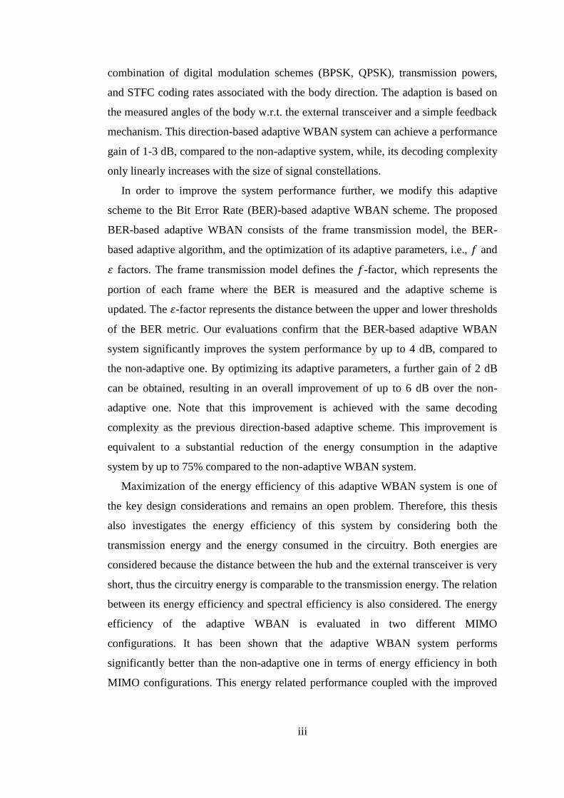
Abstract
Wireless Body Area Networks (WBAN) are networks of sensors and
communicating devices placed inside or in the proximity of a human body. Their
initial and primary application is for real-time health monitoring systems to address
the ever-increasing cost of health care. Other WBAN applications have emerged,
such as in sport, entertainment, and military. To bring an international accord on the
implementation of WBAN systems, the IEEE 802.15 Task Group (TG) 6 has
released the WBAN standard, which includes both narrow bands and the ultra-wide
band (UWB) 3.1 - 10.6 GHz, namely the Impulse Radio Ultra-Wideband (IR-UWB).
The physical layer supports the maximum data rate of 15.6 Mbps on a 499 MHz
bandwidth. However, the emergence of future bandwidth hungry WBAN
applications and the need to support the deployment of a larger number of sensor
devices require a much higher data rate and energy efficient WBAN systems. In
addition, the WBAN channels are naturally very dispersive, which is a good
condition for a Multiple Input Multiple Output (MIMO) application. Therefore, the
aim of this thesis is to investigate a high speed, robust, and energy efficient adaptive
WBAN platform. Accordingly, this thesis studies the adaptive Space-Time-
Frequency Coded Multi-Band Orthogonal Frequency Division Multiplexing (STFC
MB-OFDM) UWB WBAN system.
Initially, the performances of STFC MB-OFDM UWB WBAN systems are
analyzed and evaluated over UWB WBAN channels, and compared for two different
MIMO configurations. The effects of body directions due to human body
movements, i.e., the direction of the receiver placed on the surface of the body with
respect to (w.r.t) the fixed external transceiver, are also assessed. The evaluation
results show that the proposed STFC MB-OFDM UWB WBAN system provides a
significantly better BER performance than the conventional MB-OFDM UWB
system. One important observation is that their performance differs significantly in
different body directions, due to the availability of the Line-Of-Sight (LOS) path and
body shadowing. This observation inspires us to develop the adaptive modulation
and STFC coding schemes in order to improve the system performance.
A simple body direction based adaptive STFCMB-OFDM UWB WBAN system
is then proposed. This adaptive algorithm works based on the selection of a
iii
combination of digital modulation schemes (BPSK, QPSK), transmission powers,
and STFC coding rates associated with the body direction. The adaption is based on
the measured angles of the body w.r.t. the external transceiver and a simple feedback
mechanism. This direction-based adaptive WBAN system can achieve a performance
gain of 1-3 dB, compared to the non-adaptive system, while, its decoding complexity
only linearly increases with the size of signal constellations.
In order to improve the system performance further, we modify this adaptive
scheme to the Bit Error Rate (BER)-based adaptive WBAN scheme. The proposed
BER-based adaptive WBAN consists of the frame transmission model, the BER-
based adaptive algorithm, and the optimization of its adaptive parameters, i.e., 𝑓 and
휀 factors. The frame transmission model defines the 𝑓-factor, which represents the
portion of each frame where the BER is measured and the adaptive scheme is
updated. The 휀-factor represents the distance between the upper and lower thresholds
of the BER metric. Our evaluations confirm that the BER-based adaptive WBAN
system significantly improves the system performance by up to 4 dB, compared to
the non-adaptive one. By optimizing its adaptive parameters, a further gain of 2 dB
can be obtained, resulting in an overall improvement of up to 6 dB over the non-
adaptive one. Note that this improvement is achieved with the same decoding
complexity as the previous direction-based adaptive scheme. This improvement is
equivalent to a substantial reduction of the energy consumption in the adaptive
system by up to 75% compared to the non-adaptive WBAN system.
Maximization of the energy efficiency of this adaptive WBAN system is one of
the key design considerations and remains an open problem. Therefore, this thesis
also investigates the energy efficiency of this system by considering both the
transmission energy and the energy consumed in the circuitry. Both energies are
considered because the distance between the hub and the external transceiver is very
short, thus the circuitry energy is comparable to the transmission energy. The relation
between its energy efficiency and spectral efficiency is also considered. The energy
efficiency of the adaptive WBAN is evaluated in two different MIMO
configurations. It has been shown that the adaptive WBAN system performs
significantly better than the non-adaptive one in terms of energy efficiency in both
MIMO configurations. This energy related performance coupled with the improved

iv
bit error rate performance suggests that the proposed BER-based adaptive WBAN
scheme is an attractive physical layer option for a high speed WBAN platform.

v
Acknowledgments
First of all, I would like to express my deep gratitude to the Australia Awards for
providing me with the Australian Development Scholarship (ADS) to pursue this
PhD education. Their financial support makes this work possible. I would like to
thank to the ADS staffs at Jakarta office, particularly Mrs. Lia and Mr. Ponco
Adjiwantoro, as well as Natalie Rachlewicz and Nhan Nguyen from ADS liaison
office of University of Wollongong who have been giving me great helps, allowing
me to smoothly study at the University of Wollongong.
My sincerest gratitude goes to my supervisors, Dr. Le Chung Tran and Prof.
Farzad Safaei. Their constant academic support, guidance and encouragement have
given me the confidence necessary to conduct this work. I am lucky to have the
opportunity to learn from their vast knowledge, allowing me to build up my own
competence. Apart from their professional supports, their friendship and valuable
advice also have given me enlightenment and strength to navigate through this long
and difficult journey.
I have found many wonderful friends and colleagues during this study, with
whom knowledge sharing has been exchanged and good friendship has been knitted.
In particular, I would like to thank to Mohammad Rusli, Ngoc Phuc Le, Zhang
Liang, Abdul Rahman, Dennis Alazigha, Caesar Wahyu, Zixuan Lin, Shahid Akhund
and Winda Nurcahyo for their fruitful discussions and warm friendship. I am also
grateful for the supports from the staffs at Faculty of Engineering and Information
Science, particularly Roslyn Causer-Temby of the School of Electrical, Computer,
and Telecommunication Engineering, Lidija Dordevski of the ICT Research Institute,
and Bonnie Evans.
Last but not least, my family has been the greatest source of strength and
motivation to proceed through up and down time. Their abundant love and supports
have been always poured upon me throughout this PhD study. I would like to
dedicate this work to them, to my parents, to my wife and my children. Special
thanks also goes to my extended families, my brothers, sisters and their families, for
their love and encouragement, despite the distance.
Miftadi Sudjai
Wollongong, 14 August 2016

vi
Dedication
The Almighty God has blessed me with a fabulous family
to whom this thesis is dedicated
To my father Achmad Sudjai (RIP) and mother Ummi Hani
To my wife Khusnul Khotimah and our beloved children
Farrah Miftah, Lady Zaenab and Ali Jafar
vii
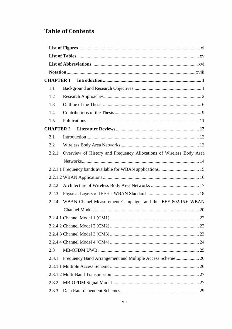
Table of Contents
List of Figures ........................................................................................................ xi
List of Tables ........................................................................................................ xv
List of Abbreviations .......................................................................................... xvi
Notation .............................................................................................................. xviii
CHAPTER 1 Introduction .................................................................................... 1
1.1 Background and Research Objectives .......................................................... 1
1.2 Research Approaches ................................................................................... 2
1.3 Outline of the Thesis .................................................................................... 6
1.4 Contributions of the Thesis .......................................................................... 9
1.5 Publications ................................................................................................ 11
CHAPTER 2 Literature Reviews ....................................................................... 12
2.1 Introduction ................................................................................................ 12
2.2 Wireless Body Area Networks ................................................................... 13
2.2.1 Overview of History and Frequency Allocations of Wireless Body Area
Networks .................................................................................................... 14
2.2.1.1 Frequency bands available for WBAN applications .................................. 15
2.2.1.2 WBAN Applications .................................................................................. 16
2.2.2 Architecture of Wireless Body Area Networks ......................................... 17
2.2.3 Physical Layers of IEEE’s WBAN Standard ............................................. 18
2.2.4 WBAN Chanel Measurement Campaigns and the IEEE 802.15.6 WBAN
Channel Models ......................................................................................... 20
2.2.4.1 Channel Model 1 (CM1) ............................................................................ 22
2.2.4.2 Channel Model 2 (CM2) ............................................................................ 22
2.2.4.3 Channel Model 3 (CM3) ............................................................................ 23
2.2.4.4 Channel Model 4 (CM4) ............................................................................ 24
2.3 MB-OFDM UWB ...................................................................................... 25
2.3.1 Frequency Band Arrangement and Multiple Access Scheme .................... 26
2.3.1.1 Multiple Access Scheme ............................................................................ 26
2.3.1.2 Multi-Band Transmission .......................................................................... 27
2.3.2 MB-OFDM Signal Model .......................................................................... 27
2.3.3 Data Rate-dependent Schemes ................................................................... 29
viii
2.4 MIMO Technique....................................................................................... 30
2.4.1 Space Time Coding .................................................................................... 33
2.4.1.1 Alamouti Scheme ....................................................................................... 34
2.4.1.2 High Rate Sezginer-Sari Scheme ............................................................... 34
2.4.2 MIMO Channel Model ............................................................................... 35
2.4.3 Diversity Gain of a MIMO System ............................................................ 38
2.4.3.1 SIMO .......................................................................................................... 39
2.4.3.2 MISO .......................................................................................................... 39
2.4.3.3 MIMO ........................................................................................................ 40
2.4.4 Capacity of a MIMO System ..................................................................... 41
2.4.4.1 Capacity of SIMO ...................................................................................... 41
2.4.4.2 Capacity of MISO ...................................................................................... 42
2.4.4.3 Capacity of MIMO ..................................................................................... 43
2.4.5 Pros and Cons of MIMO Implementations in WBAN ............................... 43
2.5 Adaptive Communication Systems ............................................................ 45
2.6 Energy Efficiency of a Communication Systems ...................................... 46
2.7 Conclusions and Research Problems Investigated in the Thesis ............... 49
CHAPTER 3 Performance Analysis of STFC MB-OFDM UWB WBAN
Systems for High Speed WBAN Services .......................................................... 53
3.1 Introduction ................................................................................................ 53
3.2 High Speed WBAN PHY Layer Requirements ......................................... 55
3.3 The Proposed STFC MB-OFDM UWB Platform ...................................... 56
3.3.1 The Channel Models .................................................................................. 56
3.3.2 STFC MB-OFDM UWB WBAN System Model ...................................... 57
3.4 Simulation Results. .................................................................................... 62
3.4.1 Performance of STFC MB-OFDM UWB WBAN System with M-PSK
Modulation in CM3 UWB WBAN Channel .......................................................... 63
3.4.2 Performance of STFC MB-OFDM UWB WBAN System with M-PSK
Modulation in CM4 UWB WBAN Channel .......................................................... 67
3.5 Conclusion ................................................................................................. 70
CHAPTER 4 Direction-based Adaptive WBAN Systems ................................ 72
4.1 Introduction ................................................................................................ 72
4.2 Direction-based Adaptive WBAN Scenario .............................................. 73
ix
4.3 Simple Adaptive WBAN System Model ................................................... 75
4.4 Direction-based Adaptive WBAN Scheme ................................................ 78
4.4.1 Adaptive Algorithm ................................................................................... 78
4.4.2 Decoding Complexity ................................................................................ 81
4.5 Performance of Direction-Based Adaptive WBAN Systems..................... 81
4.6 Conclusions ................................................................................................ 85
CHAPTER 5 BER-based Adaptive Wireless Body Area Networks ............... 87
5.1 Introduction ................................................................................................ 87
5.2 BER-based Adaptive WBAN Scenario ...................................................... 88
5.3 BER-based Adaptive WBAN System ........................................................ 89
5.3.1 System Model ............................................................................................ 89
5.3.2 Transmission Model .................................................................................. 91
5.3.3 Adaptive Algorithm ................................................................................... 92
5.4 Optimization of f and 휀 Parameters ............................................................ 93
5.5 Performance of BER-Based Adaptive WBAN system .............................. 98
5.6 Conclusions .............................................................................................. 104
CHAPTER 6 Energy Efficiency of Adaptive WBAN Systems ...................... 106
6.1 Introduction .............................................................................................. 106
6.2 Energy Efficiency Analysis of Adaptive WBAN System ....................... 107
6.2.1 Energy Efficiency of the 2I1O Configuration ......................................... 110
6.2.2 Energy Efficiency of the 2I2O Configuration ......................................... 111
6.2.3 Energy Efficiency of the Adaptive WBAN System ................................ 113
6.3 Relation between Energy Efficiency and Spectral Efficiency in Adaptive
WBAN System ........................................................................................ 115
6.3.1 Energy Efficiency vs Spectral Efficiency in 2I1O Configuration ........... 115
6.3.2 Energy Efficiency vs Spectral Efficiency in 2I2O configuration ............ 116
6.4 Numerical Results .................................................................................... 116
6.5 Conclusions ............................................................................................. 124
CHAPTER 7 Conclusions ................................................................................. 125
7.1 Conclusions .............................................................................................. 125
7.2 Recommendations for Future Works ....................................................... 128
Appendix A: Interpolated CM4 UWB WBAN Channel Model ........................ 130
A.1 Introduction .............................................................................................. 130

x
A.2 The PDP Characteristics of the IEEE CM4 UWB WBAN Channel Model
................................................................................................................. 130
A.3 Interpolation of CM4 UWB WBAN Channel .......................................... 133
A.3.1 Mathematical Model ................................................................................ 133
A.3.2 Evaluation of the Interpolated CM4 UWB WBAN Channel ................... 140
A.4 Conclusions .............................................................................................. 143
Appendix B: MATLAB Code ............................................................................... 145
Appendix C: Proof that A is a Totally Unimodullar Matrix and its ease of use in
Linear Programming ........................................................................................ 147
Bibliography 149
xi
List of Figures
Figure 1.a The research approaches used in the thesis……………………… 4
Figure 1.b The research approaches used in the thesis (continue from Figure
1.a)…. …………………………………………………………… 5
Figure 2.1 Communication links between WBAN nodes…………………... 13
Figure 2.2 Worldwide frequency allocation for WBAN……………………. 15
Figure 2.3 WBAN architecture……………………………………………… 17
Figure 2.4 The IEEE WBAN communication layer architecture…………… 18
Figure 2.5 Communication links and channel models in the WBAN………. 21
Figure 2.6 Band group arrangement………………………………………… 26
Figure 2.7 Example of the realization of multi-band transmission by using
three bands………………………………………………………. 27
Figure 2.8 The block diagram of MB-OFDM UWB transceiver…………… 28
Figure 2.9 Different configurations of a general MIMO system…………… 32
Figure 2.10 Typical block diagram of a MIMO communication system with
M-transmit antennas and N-receive antennas…………………… 32
Figure 2.11 Alamouti Scheme……………………………………………….. 34
Figure 2.12 Performance of SIMO, MISO, and MIMO systems compared to
the SISO channel in spatially white channel (𝐇 = 𝐇𝒘)
employing an Alamouti scheme and a rate of 2 bps/Hz………… 40
Figure 2.13 Capacity of SIMO, MISO, and MIMO systems in spatially white
channels (𝐇 = 𝐇𝒘) employing the Alamouti scheme (CSI is
known only to the receiver) ……………………………………... 42
Figure 2.14 Adaptive communication system block diagram………………... 45
Figure 3.1 STFC MB-OFDM UWB WBAN system………………………... 57
Figure 3.2 Performance comparison of the STFC MB-OFDM UWB and
conventional MB-OFDM systems in CM3 UWB WBAN
channel……………………………………………………........... 64
Figure 3.3 Performance of STFC MB-OFDM in CM3 UWB WBAN
Channel with M-PSK Modulations……………………………… 65
Figure 3.4 Performance of STFC MB-OFDM in CM4 UWB WBAN 67
xii
channel with M-PSK modulations………………………………
Figure 3.5 Performance of STFC MB-OFDM in CM4 UWB WBAN
channel for various body directions with Q-PSK modulation…. 68
Figure 4.1 Angle direction boundaries for adaptive decision……………… 74
Figure 4.2 Simple adaptive STFC MB-OFDM UWB WBAN system model 76
Figure 4.3 Average performance of all body direction of the non-adaptive
WBAN system in CM4 UWB WBAN channel…………………. 83
Figure 4.4 Performance of direction-based 2I1O adaptive WBAN system in
CM4 UWB WBAN channel……………………….…………….. 83
Figure 4.5 Performance of direction-based 2I2O adaptive WBAN system in
CM4 UWB WBAN channel……………………….…………….. 84
Figure 5.1 Adaptive WBAN scenario……………………….………………. 88
Figure 5.2 BER–based adaptive STFC MB-OFDM UWB WBAN system… 90
Figure 5.3 Adaptive frame transmission model……………………………... 91
Figure 5.4 Performances of non-optimized adaptive WBAN with linear and
non-linear thresholds in 2I1O……………………….…………… 98
Figure 5.5 Performances of non-optimized adaptive WBAN with linear and
non-linear thresholds in 2I2O……………………….…………… 98
Figure 5.6 Throughput of non-optimized adaptive WBAN with linear and
non-linear thresholds in 2I1O and 2I2O configurations………… 100
Figure 5.7 Performance of optimized adaptive WBAN compared to
adaptive and non-adaptive WBAN in 2I1O…………………….. 102
Figure 5.8 Performance of optimized adaptive WBAN compared to
adaptive and non-adaptive WBAN in 2I2O……………………. 102
Figure 6.1 Transmission energy per bit of different adaptive schemes as a
function of distance between the hub and the WAP in 2I1O
configuration……….……………………………………………. 118
Figure 6.2 Transmission energy per bit of different adaptive schemes as a
function of distance between the hub and the WAP in 2I2O
configuration……….…………………………..……………….. 118
Figure 6.3 Comparison of energy efficiency as a function of distance
between the non-adaptive and the adaptive WBAN systems in
2I1O…………………………..…………………………………. 120

xiii
Figure 6.4 Comparison of energy efficiency as a function of distance
between the non-adaptive and the adaptive WBAN systems in
2I2O ………………...…………………………………………… 120
Figure 6.5 Energy efficiency as a function of spectral efficiency in the
adaptive WBAN system for two different MIMO configurations
at d = 4m…………………………………..……………………... 122
Figure A.1 Power delay profile of the original CM4 at body direction BD =
00, number of multipath L = 438………………………………… 131
Figure A.2 Power delay profile of the original CM4 at BD = 900 and L =
406……………………………………………………………….. 131
Figure A.3 Power delay profile of the original CM4 at BD = 1800 and L =
425……………………………………………………………….. 132
Figure A.4 Power delay profile of the original CM4 at BD = 2700 and L =
407……………………………………………………………….. 132
Figure A.5 Proposed interpolated CM4 UWB WBAN channel model……… 134
Figure A.6 Power delay profile of the interpolated CM4 at BD = 10 and L =
428…………………………………............................................. 136
Figure A.7 Power delay profile of the interpolated CM4 at BD = 910 and L
= 420…………………………………………………………….. 136
Figure A.8 Power delay profile of the interpolated CM4 at BD = 1810 and L
= 402…………………………………………………………….. 137
Figure A.9 Power delay profile of the interpolated CM4 at BD = 2710 and L
= 398……………………………….. 137
Figure A.10 Power delay profile of the interpolated CM4 at BD = 450…….. 138
Figure A.11 Power delay profile of the interpolated CM4 at BD = 1350…… 139
Figure A.12 Power delay profile of the interpolated CM4 at BD = 2250…… 139
Figure A.13 Power delay profile of the interpolated CM4 at BD = 3150…… 140
Figure A.14 The performance degradation due to changing channel fading for
random body direction in quadrant I……………………………. 141
Figure A.15 The performance degradation due to changing channel fading for
random body direction in quadrant II…………………………… 141
Figure A.16 The performance degradation due to changing channel fading for
random body direction in quadrant III………………………….. 142

xiv
Figure A.17 The performance degradation due to changing channel fading for
random body direction in quadrant IV…………………………... 142

xv
List of Tables
Table 2.1 Some medical applications in the health care monitoring system…. 16
Table 2.2 CM1 parameters………………………………………………….... 22
Table 2.3 CM2 parameters………………………………………………….... 22
Table 2.4 Parameters of CM3………………………………………………… 23
Table 2.5 Properties of CM4 UWB WBAN Channel Model………………… 24
Table 2.6 Parameters of MB-OFDM UWB ……………………………….. 29
Table 3.1 Simulation Parameters……………………………………………... 63
Table 3.2 𝐸𝑏/𝑁𝑜 required to achieve BER = 10-4 in STFC MB-OFDM UWB
and MB-OFDM UWB in CM3 UWB WBAN Channel….. 64
Table 3.3 Required 𝐸𝑏/𝑁𝑜 for different M-PSK modulation in CM3 UWB
WBAN Channel, BER = 10-4……………………………………... 66
Table 3.4 BER at 𝐸𝑏
𝑁𝑜= 14 𝑑𝐵 of different body direction in CM4 UWB
WBAN channel……………………………………………………. 69
Table 4.1 2-bit angular information and the corresponding adaptive sets…… 75
Table 4.2 Direction-based adaptive WBAN algorithm……………………… 80
Table 4.3 Simulation Parameters…………………………………………….. 82
Table 5.1 BER-based adaptive WBAN algorithm…………………………… 93
Table 5.2 Simulation Parameters…………………………………………….. 97
Table 5.3 BER values at 𝐸𝑏
𝑁𝑜= 14 𝑑𝐵 for different schemes………………… 99
Table 5.4 Required 𝐸𝑏/𝑁𝑜 of the 2I1O configuration at BER = 2.27 × 10⁻² 103
Table 5.5 The required 𝐸𝑏/𝑁𝑜 of the 2I2O configuration at BER = 2 × 10⁻⁴ 103
Table 6.1 Numerical Parameters……………………………………………... 117
Table 6.2 Transmission energy consumption per bit (J/bit) for different
adaptive sets……………………………………………………….. 119
Table 6.3 Energy efficiency of the adaptive WBAN system as compared
with the non-adaptive WBAN system (measured in total energy
consumption per bit (J/bit)) ……………………………………….. 121

xvi
List of Abbreviations
3GPP The 3rd Generation Partnership Project
16-QAM 16- Quadrature Amplitude Modulation
2I1O 2 transmit and 1 receive antennas
2I2O 2 transmit and 2 receive antennas
ADC Analog to Digital Converter
AWGN Additive White Gaussian Noise
BAN Body Area Networks
BER Bit Error Rate
BPSK Binary Phase Shift Keying
CM Channel Model
CP Cyclic Prefix
CSI Channel State Information
DAC Digital to Analog Converter
dB Decibel
DCM Dual Carrier Modulation
FFT Fast Fourier Transform
GMR Giant Magneto Resistance
IEEE Institute of Electrical and Electronics Engineering
IFFT Inverse Fast Fourier Transform
i.i.d Independently and identically distributed
IR-UWB Impulse Radio Ultra-Wideband
ISI Inter Symbol Interference
LNA Low Noise Amplifier
LOS Line of Sight
LP Linear Programming
MAC Medium Access Control
MB-OFDM Multi-Band Orthogonal Frequency Division Multiplexing
MDCM Modified Dual Carrier Modulation
mHealth Mobile Health Services
MICS Medical Information and Communication Science
xvii
MIMO Multi-Input Multi-Output
ML Maximum Likelihood
M-PSK M-ary Phase Shift Keying
M-QAM M-ary Quadrature Amplitude Modulation
MRC Maximal Ratio Combining
NLOS Non-Line of Sight
OAAO Overlap-And-Add-Operation
OFDM Orthogonal Frequency Division Multiplexing
PA Power Amplifier
PAPR Peak-to-Average Power Ratio
PDP Power Delay Profile
PSD Power Spectral Density
QoS Quality of Service
QPSK Quadrature Phase Shift Keying
RF Radio Frequency
SAR Specific Absorption Rate
SER Symbol Error Rate
SISO single-input single-output
SNR Signal to Noise Ratio
STC Space-Time Coding
STFC Space-Time-Frequency Coded
TDMA Time Division Multiple Access
TUM Totally Unimodular Matrix
QoS Quality of Service
UWB Ultra-Wideband
V-BLAST Vertical-Bell Labs Layered Space-Time
WAP Wireless Access Point
WBAN Wireless Body Area Networks
WCE Wireless Capsule Endoscopy
WPAN Wireless Personal Area Networks
ZMCSCG Zero-Mean Circulant Symmetric Complex Gaussian
ZPS Zero Padded Suffix

xviii
Notation
𝑥 Scalar symbol
�̃� Estimated scalar symbol
�̅� Average value (italic uppercase letter bar)
x̅ , 𝐱 Vector (lowercase letter bar, or bold-lowercase letter)
x̃̅ Estimated vector
𝐗 Matrix (bold-uppercase letter)
𝑎𝑖,𝑗 𝑖-th coloumn and 𝑗-th row component of a matrix
det(𝐗) Determinant of Matrix 𝐗
𝐗′ Submatrix of 𝐗
𝐗−1 Inverse of matrix 𝐗
𝐗𝑇 Transpose of matrix 𝐗
𝐗𝐻 Hermitian transpose of matrix 𝐗
𝐈 Identity matrix
𝟏𝑄 All ones 𝑄 × 1 vector
ℝ Field of non-negative real numbers
𝐸{ } Expectation of a random variable
| | Absolute value
‖ ‖𝐹 Frobenius norm
(⋆) Linear convolution
⊛ Circular convolution
( )∗ Complex conjugate
(•) Dot (Hardamard) product
(∘) Matrix multiplication
⨂ Kronecker product

1
CHAPTER 1 INTRODUCTION
1.1 Background and Research Objectives
Wireless Body Area Networks (WBANs) have been one of the hot research topics
in wireless communication worldwide for the last ten years. WBAN initially
addressed the need of efficient real-time health care monitoring systems [1-5] to
tackle the excessive burden in the health services and the increasing cost of health
care provisions. Since then, many other applications, such as sport, entertainment,
and military applications [4], [6], [7], have also arisen. Research activities in
WBANs focus on narrowband technologies, for instance Medical Implant
Communication Service (MICS) [4] and [8], Wireless Medical Telemetry System
(WMTS) [9], and Human Body Communication (HBC) [2] and [4], as well as
wideband Impulse Radio Ultra-Wideband (IR-UWB) technology [4], [10], [11], [12].
Many proposals, including body centric channel measurements and modelling, have
been submitted to the established IEEE 802.15 task group 6 (TG), for example [13-
16] and [17-20]. To bring an international accord on the WBAN system, the IEEE
802.15 TG6 released the WBAN standard in February 2012. This WBAN standard
includes the IR-UWB wideband physical layer [21]. This standard supports the
maximum data rate of 15.6 Mbps on a 499 MHz bandwidth [21]. This wideband
UWB WBAN system is of our interest in this research.
The emergence of future bandwidth hungry WBAN applications [4] and the need
to support the deployment of a larger number of medical sensors is unavoidable. As a
consequence, these require a much higher data rate and energy efficient WBAN
system. In addition, the wideband IR-UWB based WBAN system exhibits some
shortcomings, including the expensive high frequency sampling Analog-to-Digital
Converter (ADC) due to the ultra-short impulse signal, less flexible compliance with
worldwide WBAN spectrum allocations, and the need of a high number of RAKE
fingers to exploit the rich diversity of WBAN channels [22], [23], [24]. Thus, it is
imperative to explore alternative solutions for a high speed, robust and energy-
efficient WBAN platform.
Research on the high speed WBAN system were very limited in the literature
during this investigation. For example, a channel characterization and system
modelling, using a high speed Orthogonal Frequency Division Multiplexing (OFDM)
2
approach for WBAN application, was conducted in [25]. The performance evaluation
of UWB WBAN systems utilizing receive diversity was presented in [26], [27] and
[28]. However, these research neither considered Multiple-Input Multiple-Output
(MIMO) techniques and adaptive approaches, nor took into account the energy
efficiency issue. Naturally, WBAN environments are rich in multipath diversity due to
a large scattering of the radio propagation [13]. Therefore, a MIMO application will
be a good candidate for such wireless environment. Meanwhile, Multi-Band
Orthogonal Frequency Division Multiplexing Ultra-Wideband (MB-OFDM UWB)
technology offers a high data rate up to 1 Gbps. Besides supporting the very high
speed, the MB-OFDM UWB technique is able to turn the frequency selective fading
into the frequency flat fading, and to comply with worldwide spectrum arrangement
[23-24], [29]. A MIMO MB-OFDM UWB will provide a spatial diversity on top of
time and frequency diversities, due to Space-Time-Frequency Coding (STFC)
processing [23], [30]. This threefold diversity of a STFC MB-OFDM UWB will boost
the robustness of a WBAN implementation in a severe WBAN channel. Applications
of MIMO in combination with MB-OFDM UWB in the WBAN platform have been
almost unexplored in the literature during this research work.
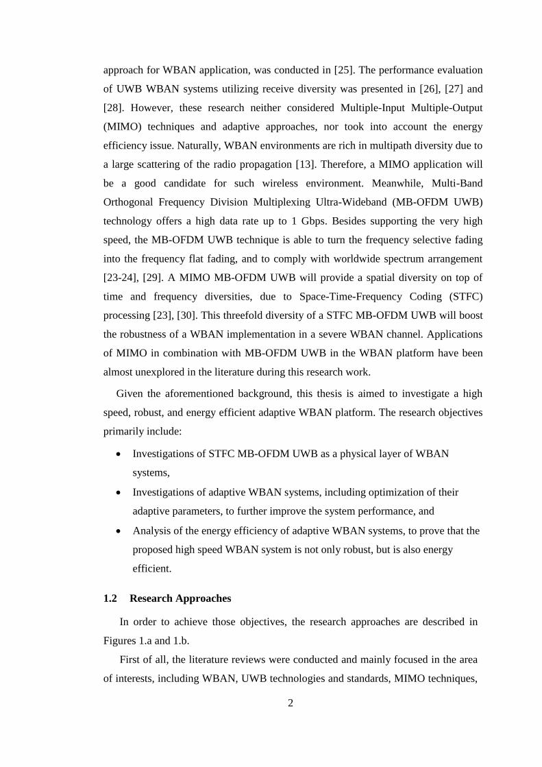
Given the aforementioned background, this thesis is aimed to investigate a high
speed, robust, and energy efficient adaptive WBAN platform. The research objectives
primarily include:
Investigations of STFC MB-OFDM UWB as a physical layer of WBAN
systems,
Investigations of adaptive WBAN systems, including optimization of their
adaptive parameters, to further improve the system performance, and
Analysis of the energy efficiency of adaptive WBAN systems, to prove that the
proposed high speed WBAN system is not only robust, but is also energy
efficient.
1.2 Research Approaches
In order to achieve those objectives, the research approaches are described in
Figures 1.a and 1.b.
First of all, the literature reviews were conducted and mainly focused in the area
of interests, including WBAN, UWB technologies and standards, MIMO techniques,
3
adaptive communication systems, and energy efficiency issues in wireless
communications. As a result, the open research problems and possible solutions were
identified, and became the basis for the investigations in this thesis.
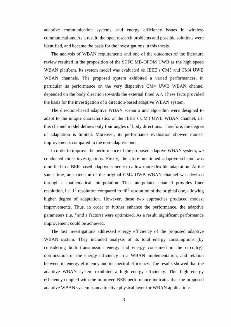
The analysis of WBAN requirements and one of the outcomes of the literature
review resulted in the proposition of the STFC MB-OFDM UWB as the high speed
WBAN platform. Its system model was evaluated on IEEE’s CM3 and CM4 UWB
WBAN channels. The proposed system exhibited a varied performances, in
particular its performance on the very dispersive CM4 UWB WBAN channel
depended on the body direction towards the external fixed AP. These facts provided
the basis for the investigation of a direction-based adaptive WBAN system.
The direction-based adaptive WBAN scenario and algorithm were designed to
adapt to the unique characteristics of the IEEE’s CM4 UWB WBAN channel, i.e.
this channel model defines only four angles of body directions. Therefore, the degree
of adaptation is limited. Moreover, its performance evaluation showed modest
improvements compared to the non-adaptive one.
In order to improve the performance of the proposed adaptive WBAN system, we
conducted three investigations. Firstly, the afore-mentioned adaptive scheme was
modified to a BER-based adaptive scheme to allow more flexible adaptation. At the
same time, an extension of the original CM4 UWB WBAN channel was devised
through a mathematical interpolation. This interpolated channel provides finer
resolution, i.e. 10 resolution compared to 900 resolution of the original one, allowing
higher degree of adaptation. However, these two approaches produced modest
improvements. Thus, in order to further enhance the performance, the adaptive
parameters (i.e. f and 휀 factors) were optimized. As a result, significant performance
improvement could be achieved.
The last investigations addressed energy efficiency of the proposed adaptive
WBAN system. They included analysis of its total energy consumptions (by
considering both transmission energy and energy consumed in the circuitry),
optimization of the energy efficiency in a WBAN implementation, and relation
between its energy efficiency and its spectral efficiency. The results showed that the
adaptive WBAN system exhibited a high energy efficiency. This high energy
efficiency coupled with the improved BER performance indicates that the proposed
adaptive WBAN system is an attractive physical layer for WBAN applications.

4
Start
Literature Reviews on area of interests: WBAN, UWB Technologies,
MIMO, Adaptive Communications techniques, Energy Efficiency
Outcomes: Most updated literature review on
WBAN, MIMO, MB-OFDM UWB, adaptive communications system, and energy efficiency topics.
Identification of open research problems and possible solutions
Proposition of STFC MB-OFDM UWB for high
speed WBAN platform
System model analysis and performance
evaluations
Outcomes: The proposed system exhibits
varied performances The system performances are
dependent of the body directions in the CM4 UWB WBAN channel
Analysis of high speed WBAN requirements
A
Research aims:Develop a high speed, robust, and energy efficient WBAN platform
Figure 1.a The research approaches used in the thesis.

5
Optimization of adaptive parameters
Outcomes:Significant improvement in the performances
Energy efficiency analysis of the optimized adaptive WBAN system
Outcomes:The system exhibits significantly high energy efficiency
STOP
Outcomes:Modest improvement in the performances
System model analysis and performance evaluations
A
Proposition of Direction-based adaptive WBAN system
Outcomes:Modest improvement in the performances
System model analysis and performance evaluations
Proposition of BER-based adaptive WBAN system
Figure 1.b The research approaches used in the thesis (continue from Figure 1.a)
6
1.3 Outline of the Thesis
This thesis focuses on the high speed adaptive WBAN platform by utilizing the
MIMO MB-OFDM UWB approach. The thesis consists of eight chapters, outlined as
follows.
Chapter 1 discusses the background and aims of this thesis, the research
approaches, the outline and key contributions of the thesis. The conference
and journal publications as the outcomes of this research are listed at the end
of this chapter.
Chapter 2 discusses the background knowledge and research activities in the
areas related to this thesis. These areas include the WBAN system, MB-
OFDM UWB standard, MIMO techniques, adaptive communication system,
and energy efficiency in wireless communications. The discussions of MIMO
are limited to the issues of our interest, such as two STBC coding schemes
(Alamouti and Sezginer-Sari codes), frequency flat fading MIMO channel
model, spatial diversity gain and capacity of MIMO assuming the channel
state information is only known to the receiver. Beside the background
knowledge necessary to understand the systems described in the rest of the
thesis, this chapter also identifies the open research problems to be addressed
and their possible solutions. As a result of this analysis, the STFC MB-
OFDM UWB technique has been proposed to be a high speed WBAN
physical layer.
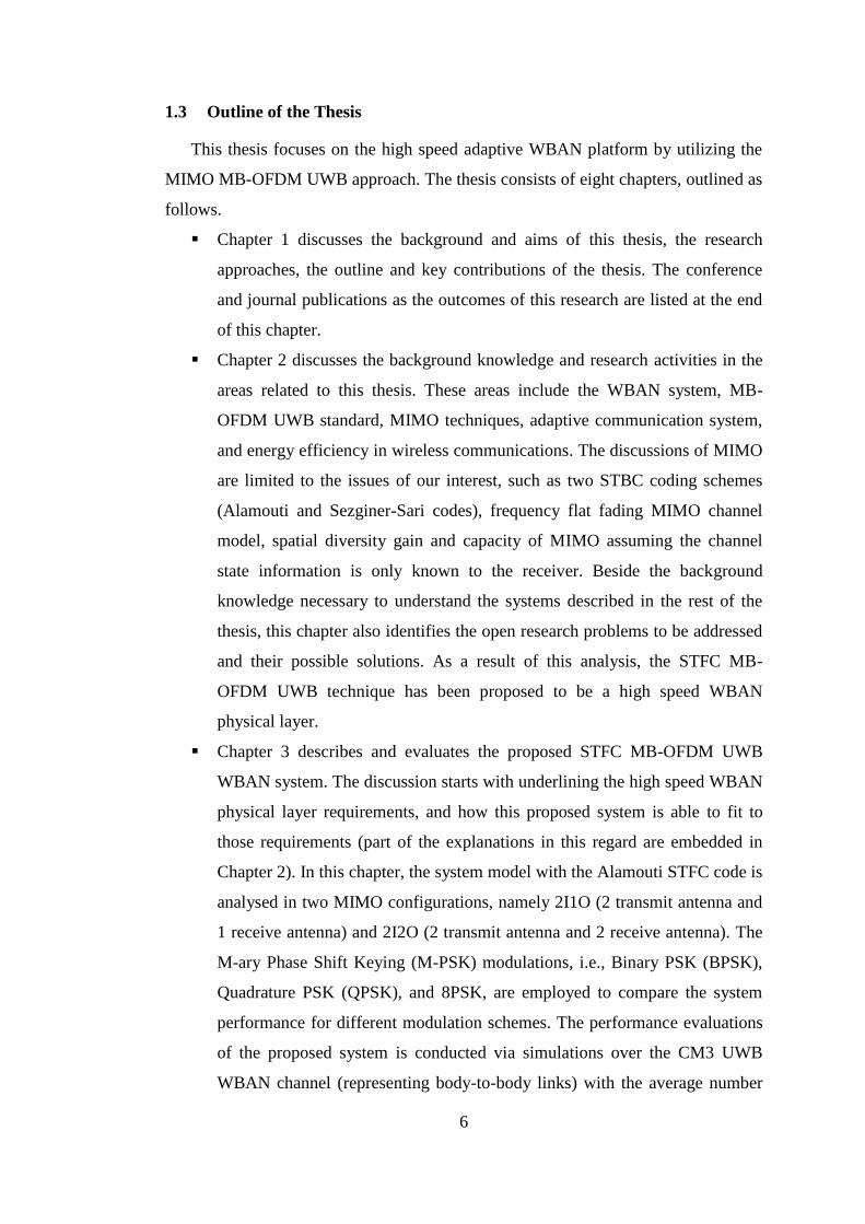
Chapter 3 describes and evaluates the proposed STFC MB-OFDM UWB
WBAN system. The discussion starts with underlining the high speed WBAN
physical layer requirements, and how this proposed system is able to fit to
those requirements (part of the explanations in this regard are embedded in
Chapter 2). In this chapter, the system model with the Alamouti STFC code is
analysed in two MIMO configurations, namely 2I1O (2 transmit antenna and
1 receive antenna) and 2I2O (2 transmit antenna and 2 receive antenna). The
M-ary Phase Shift Keying (M-PSK) modulations, i.e., Binary PSK (BPSK),
Quadrature PSK (QPSK), and 8PSK, are employed to compare the system
performance for different modulation schemes. The performance evaluations
of the proposed system is conducted via simulations over the CM3 UWB
WBAN channel (representing body-to-body links) with the average number
7
of multipath �̅� = 38, and over the CM4 UWB WBAN channel (representing
body-to-external links) with �̅� = 400. The former channel model is intended
to test the proposed system over the non-severe fading channel conditions,
while the latter is aimed to evaluate the system performance over an extreme
fading channel. An important discovery of the significantly different system
performance in different body directions due to the human body movements
has motivated us to propose of adaptive WBAN systems which will be
mentioned in the next chapter.
Chapter 4 proposes the direction-based adaptive WBAN system. The
adaptive algorithm is devised based on the four body directions of the
existing IEEE’s CM4 UWB WBAN channel. Since the two body directions,
i.e. 90o and 180o, generate similar performances, therefore only three sets of
adaptive schemes associated with three different body directions are defined.
Each set of adaptive schemes combines the QPSK or BPSK modulation with
STFC codes and power control in such a way that their total average spectral
density and average total power are the same as those in the non-adaptive
one, which is used as the benchmark, for a fair comparison. Here, two
orthogonal STFCs, namely the full rate Alamouti code and 3/2-rate Sezginer-
Sari code, are employed. Updating mechanism is conducted through a simple
feedback link with 2-bit angular information, which is assumed error free.
The system complexity analysis shows that the decoding complexity only
increases linearly with the signal constellation size. Performance evaluations
show a modest improvement compared to the non-adaptive one. Driven by
our aims to seek for a high speed, robust, and energy-efficient WBAN
system, refinement of this adaptive WBAN system is necessary in order to
improve further the performance.
Chapter 5 proposes the BER-based adaptive WBAN system. It includes the
adaptive scenarios and adaptive algorithms modified from the previous
direction-based adaptive algorithm. The algorithm is based on the measured
BER at the receiver as the metric for adaptation, in comparison with the two
BER thresholds prior known to the receiver, i.e., the lower and upper BER
thresholds (determinations of these thresholds will be explained in more
detail in this chapter). The distance between the upper and lower thresholds is
8
defined by a so-called 휀-factor. The sets of adaptive schemes used in the
algorithm are the same as the previous ones (cf. Chapter 4). As in Chapter 4,
the transmitter is updated through a simple error-free feedback channel with
2-bit information. The frame transmission model is devised, which
determines the portion of the frame (𝑓-factor), where the BER is measured
and the set of the adaptive scheme is updated. Optimization of the 𝑓 and 휀
factors is conducted to obtain the optimal system performance. This
optimized BER-based adaptive WBAN was evaluated on the interpolated
CM4 UWB WBAN channel (c.f. Appendix A), and shows a significant
improvement of up to 6 dB better than the non-adaptive one. This is
equivalent to the achievement of 75% power reduction in the optimized
adaptive WBAN system, compared to the non-adaptive one, for a similar
error performance.
Chapter 6 analyses the energy efficiency of the optimized BER-based
adaptive system proposed in Chapter 5. Here, the energy efficiency is defined
as the ratio between total power consumption and total data rate, measured in
Total Energy per transmitted Bit (TEPB) (J/b). Due to the very short distance
between the transmitter and receiver of up to 5 m in the WBAN, the energy
consumed in the circuitry is comparable to the transmission energy consumed
in the power amplifier. When the distance is so small, the circuitry energy
consumption tends to be more dominant than the transmission energy. Thus,
the energy consumption model in this analysis considers both the
transmission energy and the energy consumption in the circuit, such as in
mixers, filters, ADC/DAC, encoder/decoder, and Low Noise Amplifier
(LNA). The energy efficiency of the adaptive WBAN system is analysed and
compared to the non-adaptive WBAN system for both 2I1O and 2I2O MIMO
configurations at a certain target symbol error rate. In addition, the relation
between the energy efficiency and spectral efficiency of such system is
analysed and compared in both MIMO configurations. The performance
evaluations show that the 2I2O adaptive WBAN system outperforms the
counterparts.
Chapter 7 provides the conclusions of the thesis and discusses our possible
future works.
9
1.4 Contributions of the Thesis
The key contributions of this thesis shown in Chapter 3 to Chapter 6 are
summarized as per chapter as follow.
Chapter 3
Proposition of STFC MB-OFDM UWB as a physical layer for high speed
WBAN.
Analysis of the STFC MB-OFDM UWB system for the two MIMO
configurations, namely 2I1O and 2I2O.
Performance evaluations of the proposed STFC MB-OFDM UWB
WBAN system with three M-PSK modulation schemes, i.e. BPSK,
QPSK, and 8PSK, in the CM3 and CM4 UWB WBAN channels via
simulations. Note that, the CM3 UWB WBAN channel represents a non-
severe fading channel and the CM4 UWB WBAN channel represents an
extreme fading channel.
Investigation and analysis of the influence of body directions (due to
human body movements) to the system performances.
Discovery of the dependence of the system performance on different body
directions (the direction of the receiver placed on the surface of the body
with respect to the fixed external transceiver) due to human body
movements.
The contents of this chapter have been published as a journal paper [P2] and a
conference paper [P5].
Chapter 4
Proposition of a body direction-based adaptive WBAN system based on
the WBAN physical layer proposed in Chapter 3.
Design and implementation of the body direction-based adaptive
algorithm.
Analysis and performance evaluation of the proposed body direction-
based adaptive system based on the original CM4 UWB WBAN channel
model.
Analysis of the decoding complexity of the proposed direction-based
adaptive WBAN system.
10
The contributions of Chapter 4 have been published as a journal paper [P2], and a
conference paper [P6].
Chapter 5
Proposition of a BER-based adaptive WBAN system. This adaptive
scheme is a further improved version of the aforementioned direction-
based adaptive WBAN system.
Proposition of the adaptive frame transmission model, specifying where
the BER metric for adaptation should be measured and when the adaptive
sets should be updated.
Design and implementation of the BER-based adaptive algorithm which
focuses on adapting the STFC coding rates, the modulation scheme and
signal constellation power based on the BER metric.
Optimization of the adaptive parameters, namely the portion of the frame
where the BER is measured and the adaptive scheme is updated (f-factor),
and the distance between the upper and lower thresholds of the BER
metric (휀-factor), in order to obtain an extra performance improvement
(extra power saving).
Evaluation and analysis of the performance of the BER-based adaptive
WBAN system over the interpolated CM4 UWB WBAN channel.
The contents of Chapter 5 have been published in our journal paper in [P1], and a
conference paper [P7]. Another journal paper [P3] was submitted and currently
under review for possible publication.
Chapter 6
Investigation and analysis of the energy efficiency model of the proposed
BER-based adaptive WBAN system. This includes analysis of the energy
efficiency of every set of the adaptive schemes, and analysis and
maximization of the overall energy efficiency of the adaptive WBAN
system.
Investigation and analysis of the relation between spectral efficiency and
energy efficiency of the proposed adaptive WBAN system.

11
Performance evaluation of the proposed adaptive WBAN system in terms
of energy efficiency, and in terms of relation between the spectral
efficiency and energy efficiency.
The journal paper [P4] covering the content of Chapter 6 has been submitted and
is currently under the reviewing process.
1.5 Publications
The contributions of this thesis have been evidenced by the following journals
and conferences publications.
Journal Papers:
[P1] M. Sudjai, L. C. Tran, F. Safaei and S. L. Phung, “Optimal adaptive wireless
body area networks for high speed mHealth services”, W. de Gruyter Journal
on Biomedizinische Technik, vol. 59, no.s1, pp. 750-753, Oct. 2014.
[P2] M. Sudjai, L. C. Tran and F. Safaei, “Adaptive space time frequency coded
ultra-wideband system for wireless body area network”, EURASIP Journal on
Wireless Communication and Networking, vol. 2015:36, pp. 1-11, Feb. 2015.
[P3] M. Sudjai, et. al, “High speed adaptive wireless body area networks”, Accepted
for publication in EURASIP Journal on Wireless Communication and
Networking, Mar. 2016.
[P4] M. Sudjai, L. C. Tran and F. Safaei, “On the energy efficiency of adaptive
WBAN system for mHealth Services”, under review in EAI-Endorsed
Transaction on Pervasive Health and Technology, Jul. 2016.
Conference Papers:
[P5] M. Sudjai, L. C. Tran and F. Safaei, “Performance analysis of STFC MB-
OFDM UWB in WBAN channels”, Proc. IEEE Symposium on Personal,
Indoor, Mobile Radio Communication (PIMRC), pp. 1704-1709, Sep. 2012.
[P6] M. Sudjai, L. C. Tran and F. Safaei, “A simple adaptive STFC MB-OFDM
UWB system for WBAN applications”, Proc. IEEE International Symposium
on Communication and Information Technology (ISCIT), pp. 60-65, Sep. 2013.
[P7] M. Sudjai and L. C. Tran, “A BER based adaptive STFC MB-OFDM UWB
system for WBAN applications”, Proc. IEEE International Conference on
Communication (ICC), pp. 5681-5686, Jun. 2014.
12
CHAPTER 2 LITERATURE REVIEW
2.1 Introduction
The aging society raises a serious concern in most parts of the world due to the
increasing cost of health care and provision of better health services [1-3]. The need
for more efficient real-time health monitoring systems is evident [1-3]. The lack of
flexibility and difficulties in remote monitoring systems of the existing cable
connected body sensors need to be solved. One of the intensively researched
emerging technologies to address these problems is Wireless Body Area Networks
(WBAN).
WBAN foster the advancement of personal and mobile healthcare services. It
promises an effective health monitoring system which is potentially capable of
reducing the ever-increasing healthcare cost by promoting a remote real time health
monitoring system and reducing the patients’ need to go to hospitals frequently, for
instance, for health checks and medical tests [1-5]. Moreover, WBAN are also aimed
to serve different areas of applications, including entertainment, sport and military
[1-6]. A reliable array of tiny, lightweight sensors and a robust energy-efficient
communication system are keys for the success of WBAN implementations [1-5].
The fundamental issues in WBAN designs include matters on reliability, small
size, lightweight, capacity, and energy efficiency parameters to suit their practical
implementations and health related safety issue due to its proximity to human body
[1], [2], [4]. Current and foreseeable future WBAN services require high data rates
and high quality of services [4]. The existing IEEE’s WBAN standard supports
applications with the maximum data rate of 15.6 Mbps [21]. This data rate obviously
will be insufficient to support the emerging bandwidth-hungry applications [4] and
larger deployment of high quality of service WBAN sensors. Thus, the future
WBAN platforms should be able to provide higher capacity than the current IEEE’s
WBAN standard to cope with such demand. With the aim of achieving this goal, this
thesis investigates and proposes an optimized adaptive Space-Time-Frequency
Coding Multi-Band Orthogonal Frequency Division Multiplexing Ultra-Wideband
(STFC MB-OFDM UWB) WBAN system as an alternative for a high speed WBAN
physical layer.
In order to provide a basic understanding of the system described in the thesis,
13
this chapter explains several issues as follows. Section 2.2 overviews WBAN
systems. A brief summary of the MB-OFDM UWB system and standard is given in
Section 2.3. Multiple-Input Multiple-Output (MIMO) techniques as a core in our
proposed WBAN physical layer are described in Section 2.4. Section 2.5 presents the
basic concept of a general adaptive communication system, while Section 2.6
discusses the energy efficiency principles which will be an important part of our later
analysis in this thesis. Finally, Section 2.7 presents a conclusion and research
problems addressed in this thesis.
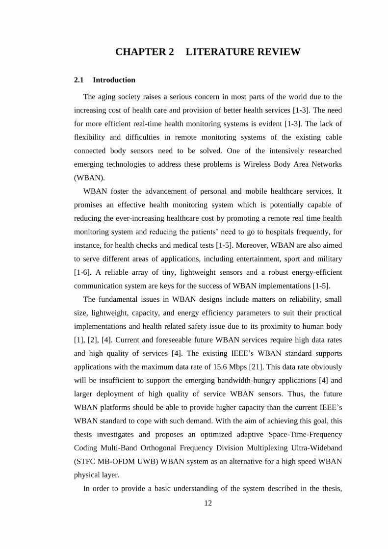
2.2 Wireless Body Area Networks
Figure 2.1 Communication links between WBAN nodes (reproduced from [13]).
WBAN is a network of sensors or communicating devices placed in, on, or off the
body. The devices could be implantable and wearable ones. Basically, three types of
nodes are defined as follows [7], [13], [21]
Implant node: A node that is placed inside the human body. This could be
immediately below the skin or deeper inside the body tissue.
Body surface node: A node that is placed on the surface of the human skin or
at most 2 cm away.
External node: A node that is not in contact with human skin (between a few
cm and up to 5 m away from the body).
The possible communication links are between implant to implant nodes, implant
to on-body nodes, implant to external nodes, on-body to on-body nodes, and on-body
to external nodes as shown in Figure 2.1. The links are unique because of the radio

14
signal propagation through the body tissues or the surface of the body [31], [32],
[33]. Different characteristics of layers of body tissues as well as the skin itself cause
different radio propagation behaviors [25], [34-42], particularly in terms of path
losses due to body’s attenuation and power delay profile as summarized in [13]. The
characterization of body centric radio channels has been measured extensively, for
instance in [14-16] and [33-42]. It is important to note that due to closeness to or
within the body, Specific Absorption Rate (SAR), i.e. the amount of electromagnetic
radiation power per kg body weight should be considered in the design and
implementation of WBAN [2], [4], [13].
2.2.1 Overview of History and Frequency Allocations of Wireless Body Area
Networks
There have been active engagements in the WBAN research in recent years [1-4],
[6], [41], [43-45]. Numerous research publications and proposals of WBAN have
been put forward. For example, Arnon, et.al conducted a comparative study of
wireless communication networks for medical applications in 2003 [44]. Various
other developments of WBAN, including the descriptions of many implantable and
wearable sensors, physical and Medium Access Control (MAC) layers, and network
architectures are provided in survey papers such as [1-5], [19]. In addition, body
centric radio propagation measurement campaigns and WBAN channel modelling
have been robustly fostering research activities on WBAN technologies and
standards [17-19], [21]. Many proposals have been submitted to the IEEE 802.15
committee [21]. In order to harmonize the development of WBAN, IEEE set up the
Technical Group 6 (TG6) within 802.15 to standardize the WBAN in November
2007, which started its operations in January 2008.
The IEEE 802.15 TG.6 is responsible for the development of WBAN standards
for applications such as medical, consumer electronics, personal entertainment and
others. To incorporate efforts on a global standard of WBAN, the IEEE TG.15.6
published a WBAN standard in February 2012 [21]. This standard supports
applications with the data rate of few kbps to maximum 15.6 Mbps on a 499 MHz
bandwidth [21]. Meanwhile, WiMedia Alliance offers an alternative technology, i.e.
Multi-Band Orthogonal Frequency Division Multiplexing Ultra-Wideband (MB-
OFDM UWB), that may be better for a high speed WBAN platform with slightly
higher complexity compared to Impulse Radio (IR)-UWB WBAN [29]. It allows
15
very high data rate applications up to 1 Gbps on a 528 MHz bandwidth, thus
potentially supporting a foreseeable future of bandwidth-hungry services. The
advantages and disadvantages of the MB-OFDM UWB compared to IR-UWB will
be discussed in Sub-section 2.2.3.
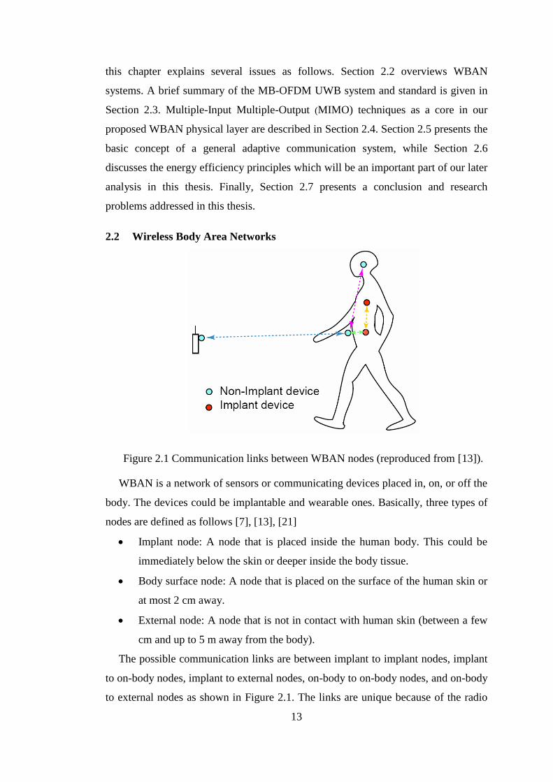
2.2.1.1 Frequency bands available for WBAN applications
Figure 2.2 Worldwide frequency allocation for WBAN (reproduced from [4]).
Figure 2.2 shows some available bands currently allocated for WBAN
applications worldwide. These frequency allocations accommodate not only the
IEEE 802.15.6 standard, but also other WBAN technologies. Some technologies
such as Medical Implant Communication Service (MICS) [8] and Wireless Medical
Telemetry System (WMTS) [9] are already in operation before the release of the
IEEE WBAN standard. Both technologies cater exclusively for body-worn and
implant medical communication services. MICS operates on 401-406 MHz [8] with
the maximum data rate of 400 kbps and is available particularly in Japan. The
implant devices such as cardiac pacemaker, implant defibrillator and neuro-
stimulator can be supported by the MICS [4]. WMTS operates on several bands as
shown in Figure 2.2 [9], and offers the maximum data rate of 1 Mbps, allowing
applications such as camera-endoscope pill [4]. WMTS bands are available in Japan,
North America, Europe, and Australia. Human Body Communication (HBC) uses the
human body as a communication medium, and it is a part of the IEEE WBAN
standard. It operates on 5 - 50 MHz [4], [21]. The unlicensed Industrial, Scientific,
and Medical (ISM) bands may be utilized for WBAN applications. However, these
ISM bands are occupied by many existing applications. Therefore, it must be
considered very carefully for WBAN applications due to the co-existence issue. The
UWB band from 3.1 – 10.6 GHz offer higher data rate and challenging option due to
its rich diversity wideband channel. By regulation [46], it operates on a bandwidth
50 5
HBC MICS WMTS ISM ISM MBAN UWB f(MHz)
401 406 420 450 863 870 902 928 1395 1429 2360 2400 2500 3100 10600
Japan Europe Japan
North America
New Zealand
Australia
Worldwide
16
more than 500 MHz with the power spectral density less than -41.25 dBm/MHz. The
current IEEE WBAN standard includes the IR-UWB technology with the maximum
data rate of 15.6 Mbps. However, it is possible to exploit another UWB technology,
i.e. MB-OFDM UWB [29], for a higher speed WBAN physical layer.
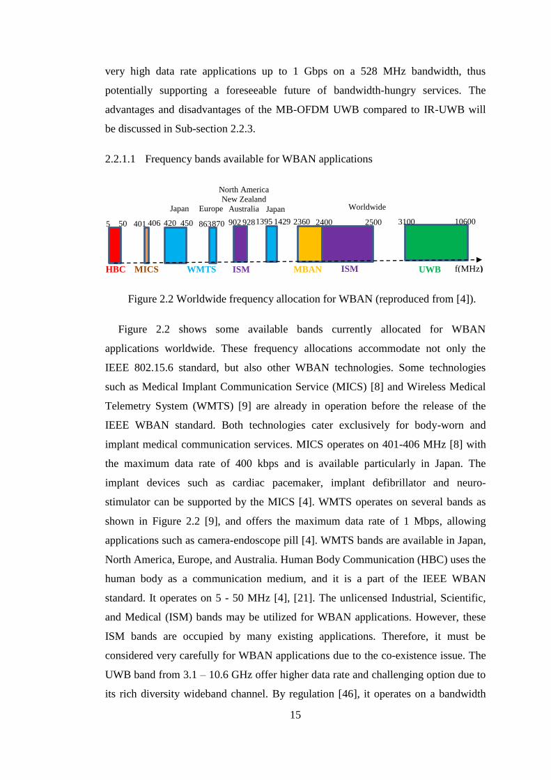
2.2.1.2 WBAN Applications
WBAN opens up numerous potential applications, not only for healthcare
services, but also for sport, entertainment and military applications [1-5]. Recent
efforts focus more on healthcare monitoring systems and treatments because WBAN
can potentially streamline real-time health checks and reduce the excessive burden of
the healthcare in many developing countries [1-5].
Table 2.1 Some medical applications in the healthcare monitoring system.
Applications Bit rate Required
BER
Glucose level monitor < 1 kbps < 10-10
Drug delivery <16 kbps < 10-10
EEG 86.4 kbps < 10-10
Voice 50-100 kbps < 10-3
ECG 192 kbps < 10-10
Deep brain stimulation < 320 kbps < 10-10
Capsule endoscope 1 Mbps < 10-10
Audio streaming 1 Mbps < 10-5
EMG 1.536 Mbps < 10-10
Video streaming < 10 Mbps < 10-3
128-Channel Neural
Recording System
> 10 Mbps N.A
Sensors and actuators are key components of a WBAN application. They may be
placed on the human body or implanted inside the body. Accordingly, their size and
physical compatibility to human tissues are crucial. With WBAN sensors attached to
the patients’ body, their health conditions potentially can be monitored continuously
without even going to the hospital in many cases. Numerous applications are
17
explained in many survey papers such as [1-5] and [7]. Summary of some
applications with the associated sensor requirements are presented in Table 2.1.
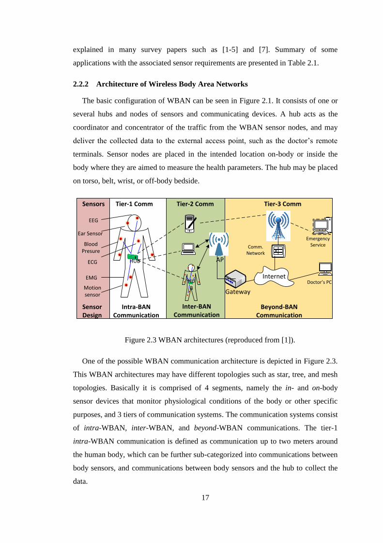
2.2.2 Architecture of Wireless Body Area Networks
The basic configuration of WBAN can be seen in Figure 2.1. It consists of one or
several hubs and nodes of sensors and communicating devices. A hub acts as the
coordinator and concentrator of the traffic from the WBAN sensor nodes, and may
deliver the collected data to the external access point, such as the doctor’s remote
terminals. Sensor nodes are placed in the intended location on-body or inside the
body where they are aimed to measure the health parameters. The hub may be placed
on torso, belt, wrist, or off-body bedside.
Sensors Tier-1 Comm Tier-2 Comm Tier-3 Comm
EEG
Ear Sensor
Blood Presure
ECG
EMG
Motion sensor
Sensor Design
Intra-BAN Communication
Inter-BAN Communication
Beyond-BAN Communication
HUB
HUB
AP
Gateway
InternetDoctor s PC
Comm. Network
Emergency Service
Figure 2.3 WBAN architectures (reproduced from [1]).
One of the possible WBAN communication architecture is depicted in Figure 2.3.
This WBAN architectures may have different topologies such as star, tree, and mesh
topologies. Basically it is comprised of 4 segments, namely the in- and on-body
sensor devices that monitor physiological conditions of the body or other specific
purposes, and 3 tiers of communication systems. The communication systems consist
of intra-WBAN, inter-WBAN, and beyond-WBAN communications. The tier-1
intra-WBAN communication is defined as communication up to two meters around
the human body, which can be further sub-categorized into communications between
body sensors, and communications between body sensors and the hub to collect the
data.
18
The tier-2 inter-WBAN communication is outlined as the links between sensor
nodes to/from one or several Access Points (AP). AP may be the existing Wireless
Local Area Networks (WLAN), cellular infrastructure or ad hoc networks deployed
on emergency or special purposes. Further, the links could be extended to the tier-3
which connects the inter-WBAN with the external networks, allowing connection
between a WBAN and worldwide communication clouds. This thesis focuses on the
tier-1 and tier-2, particularly it considers the communication links between sensors
and the hub, as well as between the hub (as the concentrator of data from various
sensors) and the external access point.
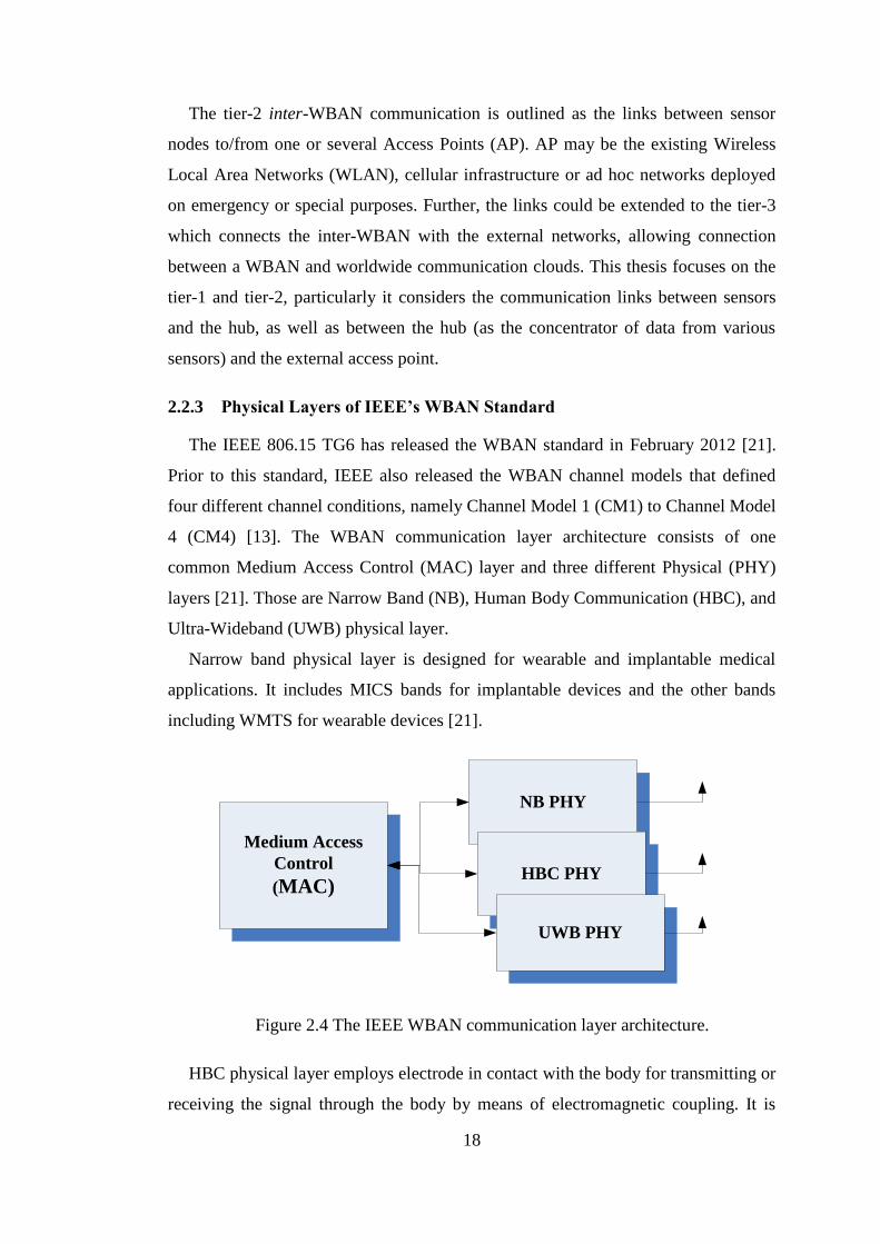
2.2.3 Physical Layers of IEEE’s WBAN Standard
The IEEE 806.15 TG6 has released the WBAN standard in February 2012 [21].
Prior to this standard, IEEE also released the WBAN channel models that defined
four different channel conditions, namely Channel Model 1 (CM1) to Channel Model
4 (CM4) [13]. The WBAN communication layer architecture consists of one
common Medium Access Control (MAC) layer and three different Physical (PHY)
layers [21]. Those are Narrow Band (NB), Human Body Communication (HBC), and
Ultra-Wideband (UWB) physical layer.
Narrow band physical layer is designed for wearable and implantable medical
applications. It includes MICS bands for implantable devices and the other bands
including WMTS for wearable devices [21].
Medium Access
Control
(MAC)
NB PHY
HBC PHY
UWB PHY
Figure 2.4 The IEEE WBAN communication layer architecture.
HBC physical layer employs electrode in contact with the body for transmitting or
receiving the signal through the body by means of electromagnetic coupling. It is

19
designed to exchange data between devices by body-to-body touching. It operates on
a 21 MHz bandwidth and provides data rates of 164 kbps, 328 kbps, 656 kbps, and
1.3125 Mbps. However, its effectiveness depends on the size of the coil, and the data
rate is low [21].
UWB physical layer is based on Impulse Radio (IR)-UWB and wideband
Frequency Modulation (FM)-UWB. FM-UWB employs a combination of
Continuous Phase-Gaussian Frequency Shift Keying (CP-GFSK) and a wideband
FM modulation. FM-UWB provides the data rate of 202.2 kbps [21]. In addition, two
modes of FM-UWB operations have been defined, i.e. default mode and high Quality
of Service (QoS) mode [21]. The default mode is used for both medical and non-
medical applications. While the high QoS mode is used for high priority medical
applications. Meanwhile, IR-UWB operates on the UWB band and has 11 channels
with a 499.2 MHz bandwidth for each channel. This UWB technology utilizes either
a single pulse or a burst of pulses for transmission per information symbol.
Moreover, IR-UWB employs either On-Off signaling or a Differential
Binary/Quadrature Phase Shift Keying (DBPSK/DQPSK) modulation. The data rates
vary from 394.8 kbps to 12.636 Mbps and from 487 kbps to maximum of 15.6 Mbps
for the On-Off signaling and the DBPSK/DQPSK modulation, respectively [21]. The
advantage of the IR-UWB is that it requires a relatively simple radio design [10],
[22], [47], [48]. However, this single carrier IR-UWB technology exhibits some
shortcomings, such as:
The complexity for processing the ultrashort impulse signal of the Radio
Frequency (RF) and the Analog circuit design including high speed Analog to
Digital Converter (ADC), which requires very high sampling rate, is high
[22-24]. These constraints become an impediment in the implementations.
The worldwide WBAN spectrum allocations are different from one country
or region to the other region as described in Figure 2.2. Thus, operating with
a single carrier in such a wide bandwidth offers less flexibility in compliance
with this worldwide spectrum management [24].
The IR-UWB receiver requires a high number of RAKE fingers to capture
significant number of multipath signals, in order to gain from a rich diversity
of the WBAN channel [23-24]. As a result, the overall transceiver complexity
increases.

20
Even though this IR-UWB WBAN standard has been considered sufficient to
support current medical applications, the maximum data rate of 15.6 Mbps of
this technology will make it difficult to cope with the future growth of
bandwidth-hungry services such as multimedia applications. For example, a
single 128-Channel Neural Recording System requires data rate more than 10
Mbps (c.f. Table 2.1). Thus, it is impossible for the IR-UWB WBAN
technology to support multiple 128-Channel Neural recording applications, or
to support this application simultaneously with other high data rate
applications, such as EMG and video streaming (c.f. Table 2.1). The IR-
UWB WBAN is also considered inadequate to support the deployment of a
larger number of WBAN sensors for multi-purpose applications at the same
time.
The IR-UWB WBAN does not support a full frequency duplex
communication (transmission on one band and reception on another band).
The full frequency duplex communication could be useful for cooperative
communication in WBAN, because it offers time delay reduction leading to
increase energy efficiency [49-50].
With regard to these considerations and given the drawbacks of IR-UWB
implementation mentioned previously, it is essential to explore other alternative
physical layers for robust high speed WBAN applications. It is worth to mention, that
the disadvantages of the IR-UWB technology are the advantages of the other UWB
technology called MB-OFDM UWB. That means the MB-OFDM UWB technology
provides favorable properties, as opposite to the IR-UWB’s shortcomings. The only
drawback of this MB-OFDM UWB is that the transmitter is slightly more complex
because it requires an IFFT, and the peak-to-average ratio (PAPR) may be slightly
higher than that of the IR-UWB approaches [22]. However, the investigation in [137]
found, that the performance of the MB-OFDM UWB scheme was better than the IR-
UWB scheme at the same 𝐸𝑏 𝑁0⁄ [137]. Therefore, in this thesis we use the MB-
OFDM UWB for high speed WBAN platform and is described in Section 2.3.
2.2.4 WBAN Chanel Measurement Campaigns and the IEEE 802.15.6 WBAN
Channel Models
Radio propagation in, on, and surrounding a human body is greatly affected by the
environment, posture, activities, and human tissues [13], [32-42]. Numerous
21
measurement campaigns on body centric propagations have been conducted to
characterize the body centric channel, including UWB channels in the frequency
bands of 3.1 – 10.6 GHz. For example, Takada, et.al showed that the body centric
channel varies according to the type of antennas, the position and orientation of
antennas with respect to the body, the posture and motion of the body, and the
variation of the human body itself [33]. Wang, et.al suggested that the body
shadowing is a prominent factor in short-range body-centric communications [34].
The effect of locations of on-body devices, body size as well as the movement of the
body was investigated in [35–40]. Finally, the IEEE 802.15 TG6 in [13] has
summarized and proposed four channel models CM1–CM4 for WBAN applications,
which comprise seven implementation scenarios, i.e. from Scenario 1 (S1) to
Scenario 7 (S7). These channel models aim for the performance evaluation of the
physical layers from various proposals and measurement campaigns.
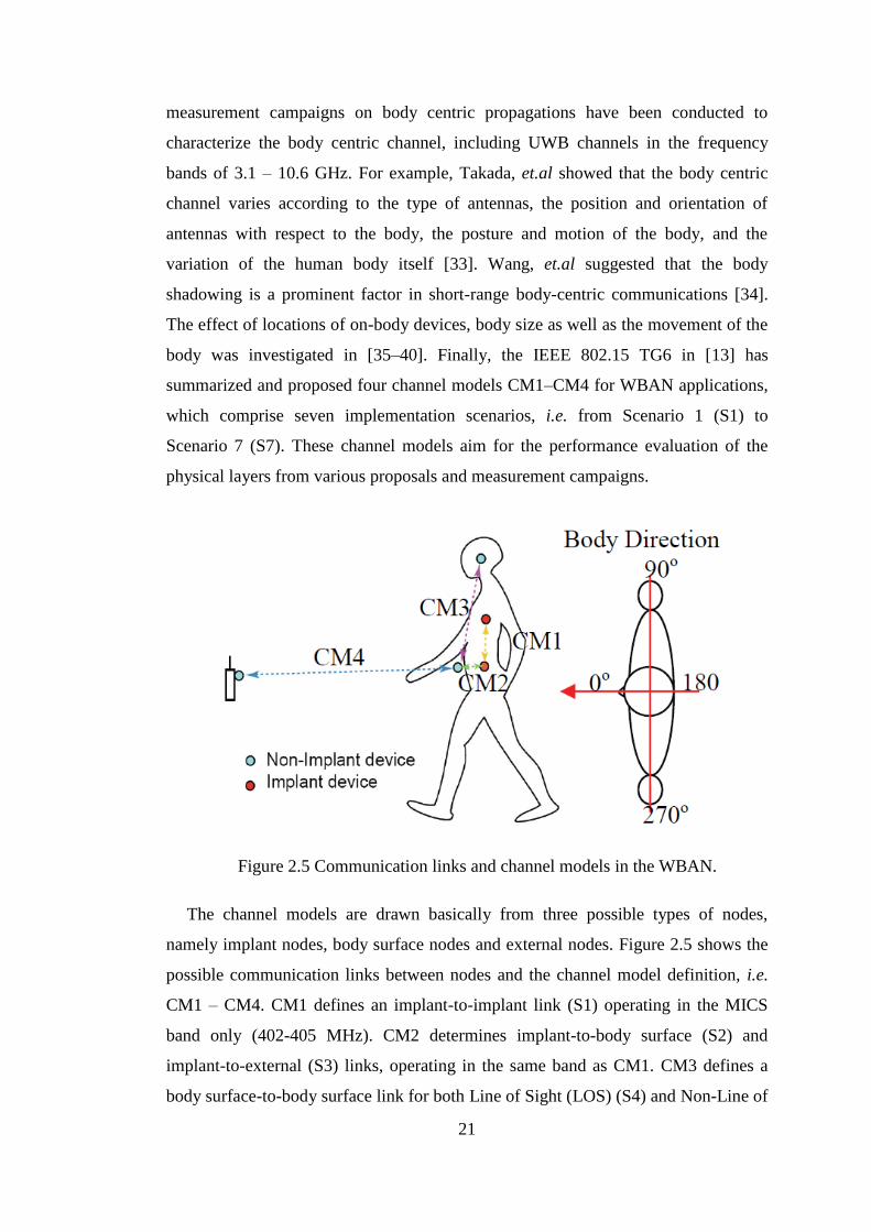
Figure 2.5 Communication links and channel models in the WBAN.
The channel models are drawn basically from three possible types of nodes,
namely implant nodes, body surface nodes and external nodes. Figure 2.5 shows the
possible communication links between nodes and the channel model definition, i.e.
CM1 – CM4. CM1 defines an implant-to-implant link (S1) operating in the MICS
band only (402-405 MHz). CM2 determines implant-to-body surface (S2) and
implant-to-external (S3) links, operating in the same band as CM1. CM3 defines a
body surface-to-body surface link for both Line of Sight (LOS) (S4) and Non-Line of
22
Sight (NLOS) (S5) scenarios. CM3 is intended to operate in seven different bands,
including the UWB band (3.1 – 10.6 GHz). CM4 determines a body surface-to-
external link for both LOS (S6) and NLOS (S7). It is applied to three different
frequency bands, including the UWB band. CM4 also takes into consideration the
body direction (or direction of the transceiver placed on the body) toward a fix
external access point as a result of the movement of the body. Due to our focus on
the UWB WBAN system, we will only consider CM3 and CM4 of the UWB band in
this thesis. Yet, to get a clearer view of the differences between those channel
models, a brief review of CM1 and CM2 characteristics is also included in this
literature review.
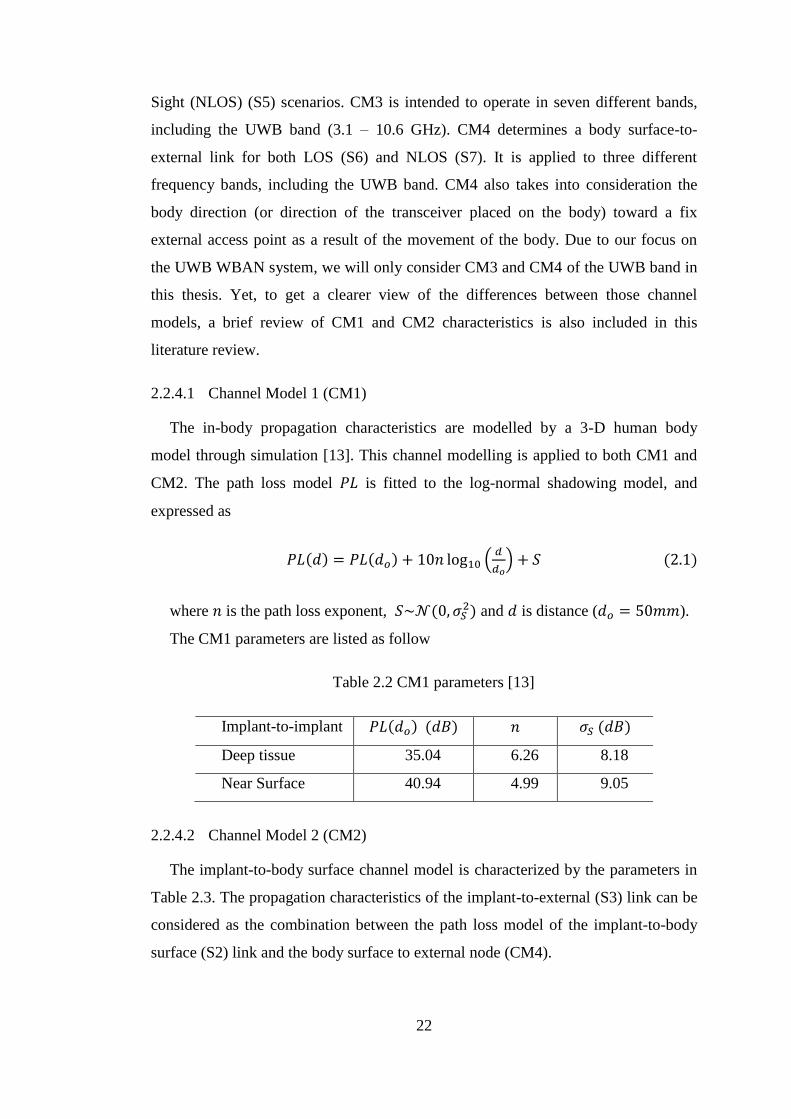
2.2.4.1 Channel Model 1 (CM1)
The in-body propagation characteristics are modelled by a 3-D human body
model through simulation [13]. This channel modelling is applied to both CM1 and
CM2. The path loss model 𝑃𝐿 is fitted to the log-normal shadowing model, and
expressed as
𝑃𝐿(𝑑) = 𝑃𝐿(𝑑𝑜) + 10𝑛 log10 (𝑑
𝑑𝑜) + 𝑆 (2.1)
where 𝑛 is the path loss exponent, 𝑆~𝒩(0, 𝜎𝑆2) and 𝑑 is distance (𝑑𝑜 = 50𝑚𝑚).
The CM1 parameters are listed as follow
Table 2.2 CM1 parameters [13]
Implant-to-implant 𝑃𝐿(𝑑𝑜) (𝑑𝐵) 𝑛 𝜎𝑆 (𝑑𝐵)
Deep tissue 35.04 6.26 8.18
Near Surface 40.94 4.99 9.05
2.2.4.2 Channel Model 2 (CM2)
The implant-to-body surface channel model is characterized by the parameters in
Table 2.3. The propagation characteristics of the implant-to-external (S3) link can be
considered as the combination between the path loss model of the implant-to-body
surface (S2) link and the body surface to external node (CM4).

23
Table 2.3 CM2 parameters [13]
implant-to-body surface 𝑃𝐿(𝑑𝑜) (𝑑𝐵) 𝑛 𝜎𝑆 (𝑑𝐵)
Deep tissue 47.14 4.26 7.85
Near Surface 49.81 4.22 6.81
2.2.4.3 Channel Model 3 (CM3)
The CM3 for the UWB band is derived from a measurement campaign in a
hospital room environment [13], [15-16]. The channel response is characterized by a
Power Delay Profile (PDP) as follow
ℎ(𝑡) = ∑𝑎𝑙 exp(𝑗ϕ𝑙) 𝛿(𝑡 − 𝑡𝑙) (2.2)
𝐿−1
𝑙=0
where
10𝑙𝑜𝑔10|𝑎𝑙|2 = {
0, 𝑙 = 0
𝛾0 + 10𝑙𝑜𝑔10 (exp (−𝑡𝑙Γ)) + 𝑆 𝑙 ≠ 0
and 𝑝(𝑡𝑙|𝑡𝑙−1) = 𝜆 exp (−𝜆(𝑡𝑙 − 𝑡𝑙−1)); 𝑝(𝐿) =�̅�Lexp (�̅�)
𝐿!. 𝑎𝑙 is the path amplitude,
𝑡𝑙 is the path arrival time, and 𝜙𝑙 is the phase for the 𝑙-th path, respectively. 𝜙𝑙 is
assumed to have an uniform distribution over [0, 2). 𝐿 is the number of the arrival
paths and �̅� is the average number of arrival paths. 𝛿(𝑡) is the Dirac function, Γ is an
exponential decay with a Rician factor 𝛾0 , 𝑆 is a normally distributed random
variable with zero-mean and standard deviation of 𝜎𝑆, and 𝜆 is the path arrival rate.
The parameters of CM3 are presented in Table 2.4.
Table 2.4 Parameters of CM3
𝑎𝑙
𝛾0 -4.60 dB
Γ 59.7
𝜎𝑆 5.02 dB
𝑡𝑙 1
𝜆⁄ 1.85 ns
𝐿 �̅� 38.1
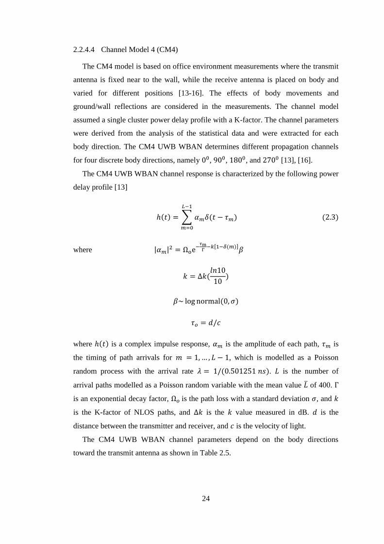
24
2.2.4.4 Channel Model 4 (CM4)
The CM4 model is based on office environment measurements where the transmit
antenna is fixed near to the wall, while the receive antenna is placed on body and
varied for different positions [13-16]. The effects of body movements and
ground/wall reflections are considered in the measurements. The channel model
assumed a single cluster power delay profile with a K-factor. The channel parameters
were derived from the analysis of the statistical data and were extracted for each
body direction. The CM4 UWB WBAN determines different propagation channels
for four discrete body directions, namely 00, 900, 1800, and 2700 [13], [16].
The CM4 UWB WBAN channel response is characterized by the following power
delay profile [13]
ℎ(𝑡) = ∑ 𝛼𝑚𝛿(𝑡 − 𝜏𝑚)
𝐿−1
𝑚=0
(2.3)
where |𝛼𝑚|2 = Ωoe−
𝜏mΓ
−𝑘[1−𝛿(𝑚)]𝛽
𝑘 = ∆𝑘(𝑙𝑛10
10)
𝛽~ log normal(0, 𝜎)
𝜏𝑜 = 𝑑/𝑐
where ℎ(𝑡) is a complex impulse response, 𝛼𝑚 is the amplitude of each path, 𝜏𝑚 is
the timing of path arrivals for 𝑚 = 1, … , 𝐿 − 1, which is modelled as a Poisson
random process with the arrival rate 𝜆 = 1/(0.501251 𝑛𝑠). 𝐿 is the number of
arrival paths modelled as a Poisson random variable with the mean value �̅� of 400. Γ
is an exponential decay factor, Ω𝑜 is the path loss with a standard deviation 𝜎, and 𝑘
is the K-factor of NLOS paths, and ∆𝑘 is the 𝑘 value measured in dB. 𝑑 is the
distance between the transmitter and receiver, and 𝑐 is the velocity of light.
The CM4 UWB WBAN channel parameters depend on the body directions
toward the transmit antenna as shown in Table 2.5.
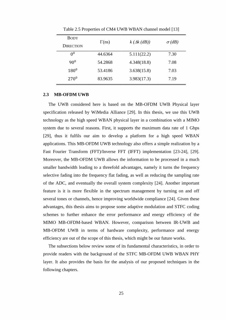
25
Table 2.5 Properties of CM4 UWB WBAN channel model [13]
BODY
DIRECTION (ns) k (k (dB)) (dB)
00 44.6364 5.111(22.2) 7.30
900 54.2868 4.348(18.8) 7.08
1800 53.4186 3.638(15.8) 7.03
2700 83.9635 3.983(17.3) 7.19
2.3 MB-OFDM UWB
The UWB considered here is based on the MB-OFDM UWB Physical layer
specification released by WiMedia Alliance [29]. In this thesis, we use this UWB
technology as the high speed WBAN physical layer in a combination with a MIMO
system due to several reasons. First, it supports the maximum data rate of 1 Gbps
[29], thus it fulfils our aim to develop a platform for a high speed WBAN
applications. This MB-OFDM UWB technology also offers a simple realization by a
Fast Fourier Transform (FFT)/Inverse FFT (IFFT) implementation [23-24], [29].
Moreover, the MB-OFDM UWB allows the information to be processed in a much
smaller bandwidth leading to a threefold advantages, namely it turns the frequency
selective fading into the frequency flat fading, as well as reducing the sampling rate
of the ADC, and eventually the overall system complexity [24]. Another important
feature is it is more flexible in the spectrum management by turning on and off
several tones or channels, hence improving worldwide compliance [24]. Given these
advantages, this thesis aims to propose some adaptive modulation and STFC coding
schemes to further enhance the error performance and energy efficiency of the
MIMO MB-OFDM-based WBAN. However, comparison between IR-UWB and
MB-OFDM UWB in terms of hardware complexity, performance and energy
efficiency are out of the scope of this thesis, which might be our future works.
The subsections below review some of its fundamental characteristics, in order to
provide readers with the background of the STFC MB-OFDM UWB WBAN PHY
layer. It also provides the basis for the analysis of our proposed techniques in the
following chapters.
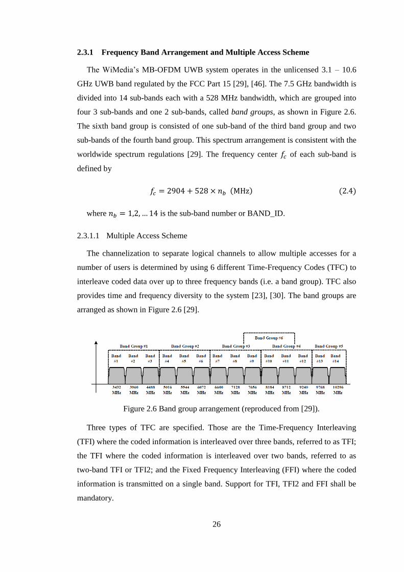
26
2.3.1 Frequency Band Arrangement and Multiple Access Scheme
The WiMedia’s MB-OFDM UWB system operates in the unlicensed 3.1 – 10.6
GHz UWB band regulated by the FCC Part 15 [29], [46]. The 7.5 GHz bandwidth is
divided into 14 sub-bands each with a 528 MHz bandwidth, which are grouped into
four 3 sub-bands and one 2 sub-bands, called band groups, as shown in Figure 2.6.
The sixth band group is consisted of one sub-band of the third band group and two
sub-bands of the fourth band group. This spectrum arrangement is consistent with the
worldwide spectrum regulations [29]. The frequency center 𝑓𝑐 of each sub-band is
defined by
𝑓𝑐 = 2904 + 528 × 𝑛𝑏 (MHz) (2.4)
where 𝑛𝑏 = 1,2, … 14 is the sub-band number or BAND_ID.
2.3.1.1 Multiple Access Scheme
The channelization to separate logical channels to allow multiple accesses for a
number of users is determined by using 6 different Time-Frequency Codes (TFC) to
interleave coded data over up to three frequency bands (i.e. a band group). TFC also
provides time and frequency diversity to the system [23], [30]. The band groups are
arranged as shown in Figure 2.6 [29].
Figure 2.6 Band group arrangement (reproduced from [29]).
Three types of TFC are specified. Those are the Time-Frequency Interleaving
(TFI) where the coded information is interleaved over three bands, referred to as TFI;
the TFI where the coded information is interleaved over two bands, referred to as
two-band TFI or TFI2; and the Fixed Frequency Interleaving (FFI) where the coded
information is transmitted on a single band. Support for TFI, TFI2 and FFI shall be
mandatory.

27
Within the first four and the sixth band groups, four TFCs using TFI and three
TFCs using each of TFI2 and FFI are defined, thereby, providing support for up to
ten channels in each band group. For the fifth band group, two TFCs using FFI and
one using TFI2 are defined. For the sixth band group, the FFI channels and one of
the TFI2 channels overlap fully with channels in the third and fourth band groups.
Not all channels are designed to be mutually orthogonal. Thus, total 53 channels are
specified in the standard [29].
2.3.1.2 Multi-Band Transmission
One example of the realization of multi-band transmission using band group #1 is
depicted in Figure 2.7. The first symbol is transmitted on Band#1 (𝑓𝑐 = 3432 MHz),
the second symbol is transmitted on Band #2, the third symbol on Band #3, resulting
in TFC {123123}. It can be seen that each symbol consists of an OFDM symbol (the
output of IFFT) appended by a Zero Padded Suffix (ZPS). The ZPS has two
functions, namely to mitigate the multipath effect, and to provide a time window to
allow the transceiver to switch between different center frequencies [23], [30].
OFDM symbol
ZPS
Symbol
Freq. (MHz)
Band no.1
Band no.2
Band no.3
Time
3168
3696
4224
4752
Figure 2.7 Example of multi-band transmission realization by using three bands.
2.3.2 MB-OFDM Signal Model
The structure of a MB-OFDM UWB transceiver is generally similar to the
conventional OFDM, except that it operates on multiband frequencies to interleave
the transmitted symbols. One of the examples of the MB-OFDM UWB transceiver
structure is depicted in Figure 2.8 [30].
At the transmitter, the data (bit stream) is convolutionally encoded and interleaved
before symbol mapping by a modulator, e.g. QPSK. The stream of modulated
symbols is divided by a serial-to-parallel converter into 𝑁𝐷 parallel series of data
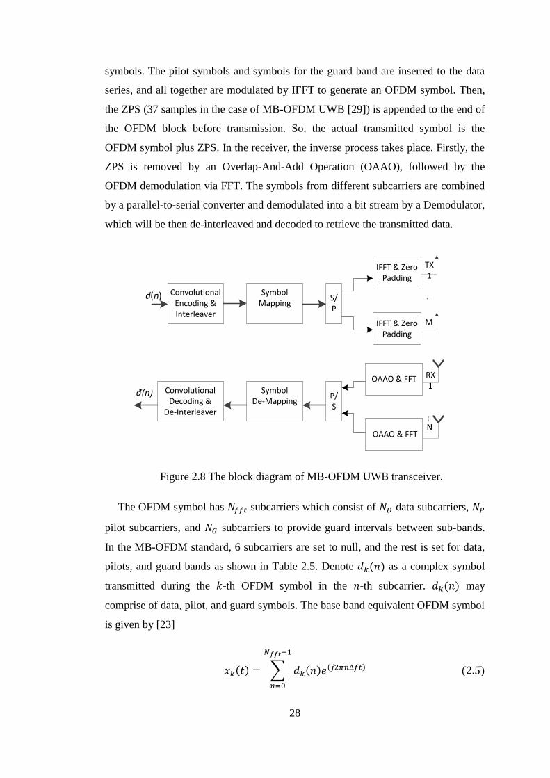
28
symbols. The pilot symbols and symbols for the guard band are inserted to the data
series, and all together are modulated by IFFT to generate an OFDM symbol. Then,
the ZPS (37 samples in the case of MB-OFDM UWB [29]) is appended to the end of
the OFDM block before transmission. So, the actual transmitted symbol is the
OFDM symbol plus ZPS. In the receiver, the inverse process takes place. Firstly, the
ZPS is removed by an Overlap-And-Add Operation (OAAO), followed by the
OFDM demodulation via FFT. The symbols from different subcarriers are combined
by a parallel-to-serial converter and demodulated into a bit stream by a Demodulator,
which will be then de-interleaved and decoded to retrieve the transmitted data.
TX 1
. .
M
RX 1
N
d(n) Convolutional Encoding & Interleaver
Symbol Mapping
S/P
IFFT & Zero Padding
IFFT & Zero Padding
OAAO & FFT
OAAO & FFT
P/S
Symbol De-Mapping
Convolutional Decoding &
De-Interleaver
đ(n)
Figure 2.8 The block diagram of MB-OFDM UWB transceiver.
The OFDM symbol has 𝑁𝑓𝑓𝑡 subcarriers which consist of 𝑁𝐷 data subcarriers, 𝑁𝑃
pilot subcarriers, and 𝑁𝐺 subcarriers to provide guard intervals between sub-bands.
In the MB-OFDM standard, 6 subcarriers are set to null, and the rest is set for data,
pilots, and guard bands as shown in Table 2.5. Denote 𝑑𝑘(𝑛) as a complex symbol
transmitted during the 𝑘-th OFDM symbol in the 𝑛-th subcarrier. 𝑑𝑘(𝑛) may
comprise of data, pilot, and guard symbols. The base band equivalent OFDM symbol
is given by [23]
𝑥𝑘(𝑡) = ∑ 𝑑𝑘(𝑛)𝑒(𝑗2𝜋𝑛∆𝑓𝑡) (2.5)
𝑁𝑓𝑓𝑡−1
𝑛=0
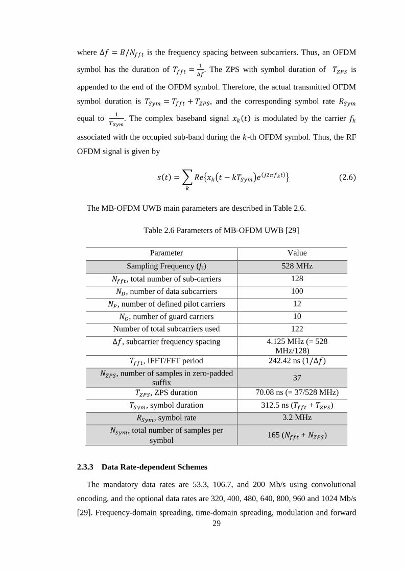
29
where ∆𝑓 = 𝐵/𝑁𝑓𝑓𝑡 is the frequency spacing between subcarriers. Thus, an OFDM
symbol has the duration of 𝑇𝑓𝑓𝑡 =1
∆𝑓. The ZPS with symbol duration of 𝑇𝑍𝑃𝑆 is
appended to the end of the OFDM symbol. Therefore, the actual transmitted OFDM
symbol duration is 𝑇𝑆𝑦𝑚 = 𝑇𝑓𝑓𝑡 + 𝑇𝑍𝑃𝑆, and the corresponding symbol rate 𝑅𝑆𝑦𝑚
equal to 1
𝑇𝑆𝑦𝑚. The complex baseband signal 𝑥𝑘(𝑡) is modulated by the carrier 𝑓𝑘
associated with the occupied sub-band during the 𝑘-th OFDM symbol. Thus, the RF
OFDM signal is given by
𝑠(𝑡) = ∑𝑅𝑒{𝑥𝑘(𝑡 − 𝑘𝑇𝑆𝑦𝑚)𝑒(𝑗2𝜋𝑓𝑘𝑡)}
𝑘
(2.6)
The MB-OFDM UWB main parameters are described in Table 2.6.
Table 2.6 Parameters of MB-OFDM UWB [29]
Parameter Value
Sampling Frequency (fs) 528 MHz
𝑁𝑓𝑓𝑡, total number of sub-carriers 128
𝑁𝐷, number of data subcarriers 100
𝑁𝑃, number of defined pilot carriers 12
𝑁𝐺 , number of guard carriers 10
Number of total subcarriers used 122
∆𝑓, subcarrier frequency spacing 4.125 MHz (= 528
MHz/128)
𝑇𝑓𝑓𝑡, IFFT/FFT period 242.42 ns (1/∆𝑓)
𝑁𝑍𝑃𝑆, number of samples in zero-padded
suffix 37
𝑇𝑍𝑃𝑆, ZPS duration 70.08 ns (= 37/528 MHz)
𝑇𝑆𝑦𝑚, symbol duration 312.5 ns (𝑇𝑓𝑓𝑡 + 𝑇𝑍𝑃𝑆)
𝑅𝑆𝑦𝑚, symbol rate 3.2 MHz
𝑁𝑆𝑦𝑚, total number of samples per
symbol 165 (𝑁𝑓𝑓𝑡 + 𝑁𝑍𝑃𝑆)
2.3.3 Data Rate-dependent Schemes
The mandatory data rates are 53.3, 106.7, and 200 Mb/s using convolutional
encoding, and the optional data rates are 320, 400, 480, 640, 800, 960 and 1024 Mb/s
[29]. Frequency-domain spreading, time-domain spreading, modulation and forward
30
error correction (FEC) coding are used to vary the data rates. The QPSK, Dual
Carrier Modulation (DCM), and Modified-DCM (MDCM) are used as modulation
techniques. QPSK modulation is used for the data rate 200 Mbps and lower, while
DCM is used for the data rate 320, 400, and 480 Mbps. For the data rates 640 Mb/s
and higher, the MDCM scheme is used. The FEC with rates of 1/3, 1/2, 5/8, 3/4, and
4/5 is used by employing convolutional encoding alone or combined with Low
Density Parity Check (LDPC) encoding. Both frequency and time spreading are used
for the data rates of 53.3, and 80, whereas the data rate of 106.7, 160 and 200 Mbps
only use time-domain spreading. No spreading is used for the data rate higher than
200 Mbps. For a full detail of these data rate-dependent schemes, reader may refer to
[29].
2.4 MIMO Technique
Current and foreseeable future wireless communication services show insatiable
demand for high data rates and high quality of services. Meanwhile, the bandwidth
and power as the fundamental backbone of any kind of communication systems are
both limited due to their scarce natural resource and strict regulations worldwide. In
addition, fierce competitions among telecommunication operators dictate an ever
increasing price of frequency spectrum. Bandwidth becomes very expensive and very
limited. On the other hand, strict regulations including health related issues, device
limitations, and interference and capacity issues limit stringently the transmit power.
The time and frequency diversity has long been exploited extensively in order to
achieve these goals, i.e. increasing the capacity and the reliability of the link.
However, these techniques are considered to be limited [51-55]. Thus, researchers
turn to the spatial domain processing to further improve the capacity and link quality
through MIMO techniques.
The MIMO techniques use multiple transmit and receive antennas to improve the
system performance, or to increase the capacity of a wireless system [51-52], [56-
57]. The core scheme in the MIMO techniques is the Space-Time Coding (STC). The
improvement in the system performance can be achieved through spatial diversity
[54], [55], [58] and the capacity enhancement can be obtained through spatial
multiplexing [51], [59], [60]. Several breakthroughs in the spatial diversity MIMO
research have been provided, e.g. by Wittneben who constructed the delay diversity
in 1991 [51], [57]. The first attempt in the development of STC was done by Winters
31
and Seshadri in 1994 [52], [57]. The key formulation of STC was provided by
Tarokh, et.al [54] in 1998 by proposing a space-time trellis coding (STTC), then
followed by the publication of the space-time block coding (STBC) or famously
called the Alamouti scheme by S. Alamouti [55] in 1998, which make the MIMO
techniques both practical and commercially viable. The invention of the Alamouti
scheme spurs the adoption of the MIMO technology by telecommunication industries
worldwide in the following years, e.g. CDMA2000 standard, 3GPP and WiMAX
[61-66].
The breakthrough in the spatial multiplexing MIMO research occurred a little bit
earlier. The first attempt to show the capacity gain of the MIMO was proposed by
Winters in 1987 [51], [52]. The groundbreaking results in spatial multiplexing
techniques were provided by Paulraj and Kailath in 1994 [51], [52].The fundamental
MIMO capacity analysis was provided by Telatar [51], [52] in 1995, and Foschini
[52] in 1995. The practical implementation of this spatial multiplexing was fostered
by the invention of Bell Lab Layered Space-Time (BLAST) transceiver architecture
by Foschini in 1996 [67].
The gradual development from a single-input single-output (SISO) technique to
the MIMO technology can be seen in the Figure 2.9. The SISO consists of only one
transmit antenna and one receive antenna, provide no spatial diversity. The single-
input multiple-output (SIMO) comprises of a transmit antenna and 𝑁-receive
antennas, providing a spatial diversity to the receiver. On the contrary, the multiple-
input single-output (MISO) consists of 𝑀-transmit antennas and a single receive
antenna, providing spatial diversity to the transmitter, but not to the receiver. The
MIMO with 𝑀-transmit antennas and 𝑁-receive antennas is actually an
amalgamation of SIMO and MISO, which is capable to provide the spatial diversity
in both transmitter and receiver. With this capability, great performance
improvement, particularly in the Signal to Noise Ratio (SNR) or bit error rate, can be
achieved. This improvement is called spatial diversity gain.
Spatial diversity gain allows the receiver to mitigate the channel fading, which is a
common impediment in wireless communication systems, without extra power,
bandwidth and time slot allocation. It is possible due to a multiple of (ideally
independent) copies of transmitted signals in time, frequency, and space can be
extracted by the receiver from different multipath channels. The number of
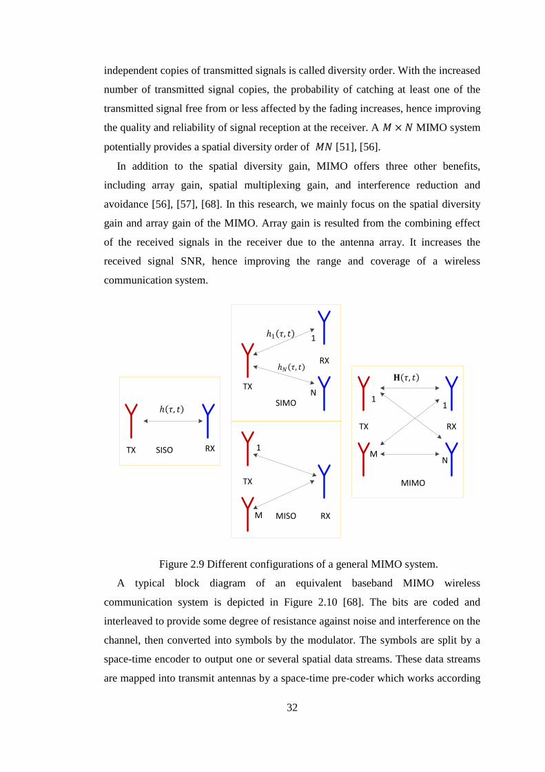
32
independent copies of transmitted signals is called diversity order. With the increased
number of transmitted signal copies, the probability of catching at least one of the
transmitted signal free from or less affected by the fading increases, hence improving
the quality and reliability of signal reception at the receiver. A 𝑀 × 𝑁 MIMO system
potentially provides a spatial diversity order of 𝑀𝑁 [51], [56].
In addition to the spatial diversity gain, MIMO offers three other benefits,
including array gain, spatial multiplexing gain, and interference reduction and
avoidance [56], [57], [68]. In this research, we mainly focus on the spatial diversity
gain and array gain of the MIMO. Array gain is resulted from the combining effect
of the received signals in the receiver due to the antenna array. It increases the
received signal SNR, hence improving the range and coverage of a wireless
communication system.
SISO
SIMO
MISO
MIMO
TX
TX
TX
TX
RX
RX
RX
RX
1
1
M
1
1
MN
N
ℎ(𝜏, 𝑡)
ℎ1(𝜏, 𝑡)
ℎ𝑁(𝜏, 𝑡)
𝐇(𝜏, 𝑡)
Figure 2.9 Different configurations of a general MIMO system.
A typical block diagram of an equivalent baseband MIMO wireless
communication system is depicted in Figure 2.10 [68]. The bits are coded and
interleaved to provide some degree of resistance against noise and interference on the
channel, then converted into symbols by the modulator. The symbols are split by a
space-time encoder to output one or several spatial data streams. These data streams
are mapped into transmit antennas by a space-time pre-coder which works according
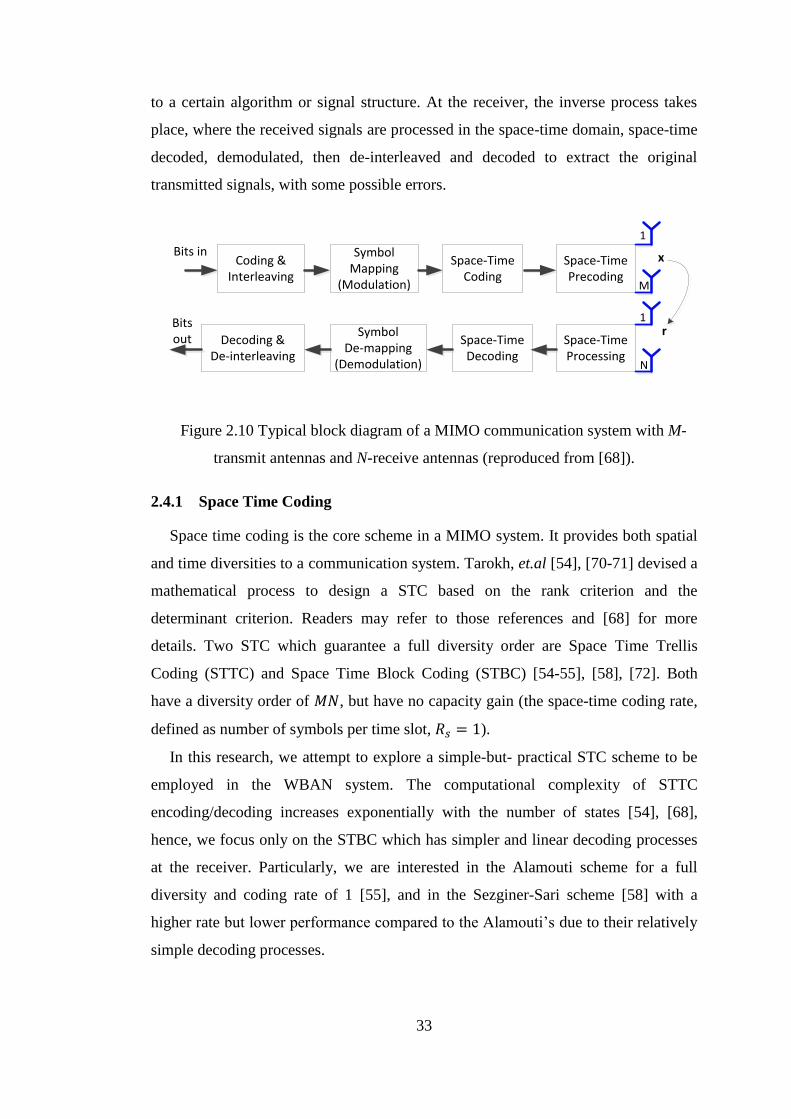
33
to a certain algorithm or signal structure. At the receiver, the inverse process takes
place, where the received signals are processed in the space-time domain, space-time
decoded, demodulated, then de-interleaved and decoded to extract the original
transmitted signals, with some possible errors.
Coding & Interleaving
Symbol Mapping
(Modulation)
Space-Time Coding
Space-Time Precoding
Space-Time Processing
Space-Time Decoding
Symbol De-mapping
(Demodulation)
Decoding & De-interleaving
x
r
Bits in
Bits out
1
1
M
N
Figure 2.10 Typical block diagram of a MIMO communication system with M-
transmit antennas and N-receive antennas (reproduced from [68]).
2.4.1 Space Time Coding
Space time coding is the core scheme in a MIMO system. It provides both spatial
and time diversities to a communication system. Tarokh, et.al [54], [70-71] devised a
mathematical process to design a STC based on the rank criterion and the
determinant criterion. Readers may refer to those references and [68] for more
details. Two STC which guarantee a full diversity order are Space Time Trellis
Coding (STTC) and Space Time Block Coding (STBC) [54-55], [58], [72]. Both
have a diversity order of 𝑀𝑁, but have no capacity gain (the space-time coding rate,
defined as number of symbols per time slot, 𝑅𝑠 = 1).
In this research, we attempt to explore a simple-but- practical STC scheme to be
employed in the WBAN system. The computational complexity of STTC
encoding/decoding increases exponentially with the number of states [54], [68],
hence, we focus only on the STBC which has simpler and linear decoding processes
at the receiver. Particularly, we are interested in the Alamouti scheme for a full
diversity and coding rate of 1 [55], and in the Sezginer-Sari scheme [58] with a
higher rate but lower performance compared to the Alamouti’s due to their relatively
simple decoding processes.
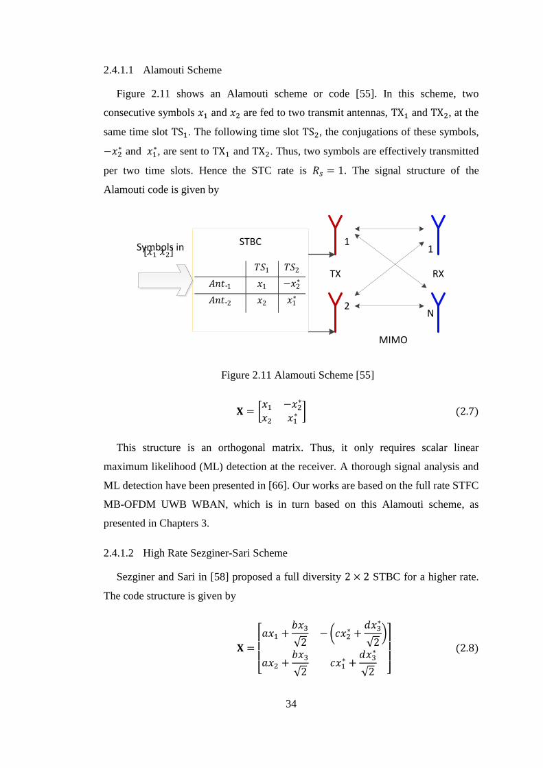
34
2.4.1.1 Alamouti Scheme
Figure 2.11 shows an Alamouti scheme or code [55]. In this scheme, two
consecutive symbols 𝑥1 and 𝑥2 are fed to two transmit antennas, TX1 and TX2, at the
same time slot TS1. The following time slot TS2, the conjugations of these symbols,
−𝑥2∗ and 𝑥1
∗, are sent to TX1 and TX2. Thus, two symbols are effectively transmitted
per two time slots. Hence the STC rate is 𝑅𝑠 = 1. The signal structure of the
Alamouti code is given by
MIMO
TX RX
11
2N
STBCSymbols in
𝑇𝑆1 𝑇𝑆2
𝐴𝑛𝑡.1 𝑥1 −𝑥2∗
𝐴𝑛𝑡.2 𝑥2 𝑥1∗
Figure 2.11 Alamouti Scheme [55]
𝐗 = [𝑥1 −𝑥2
∗
𝑥2 𝑥1∗ ] (2.7)
This structure is an orthogonal matrix. Thus, it only requires scalar linear
maximum likelihood (ML) detection at the receiver. A thorough signal analysis and
ML detection have been presented in [66]. Our works are based on the full rate STFC
MB-OFDM UWB WBAN, which is in turn based on this Alamouti scheme, as
presented in Chapters 3.
2.4.1.2 High Rate Sezginer-Sari Scheme
Sezginer and Sari in [58] proposed a full diversity 2 × 2 STBC for a higher rate.
The code structure is given by
𝐗 =
[ 𝑎𝑥1 +
𝑏𝑥3
√2−(𝑐𝑥2
∗ +𝑑𝑥3
∗
√2)
𝑎𝑥2 +𝑏𝑥3
√2𝑐𝑥1
∗ +𝑑𝑥3
∗
√2 ]
(2.8)
[𝑥1 𝑥2]
35
where a, b, c, and d are complex-valued design parameters. It creates a complex
combination of symbols from two out of three different symbols 𝑥1, 𝑥2 and 𝑥3 to be
fed to two transmit antennas in two consecutive time slots. Given the aforementioned
ST coding rate definition, this STBC effectively generates a coding rate of 3/2. The
signal analysis and detection mechanism have been presented in [58]. It was also
shown in [58] that this STBC only require a linear ML detection. However, the
penalty in terms of BER performance is 3.8 dB lower than the Alamouti scheme for
QPSK [58]. Due to its higher rate and relatively simple signal detection, this STBC
will be included in the design of our proposed adaptive STFC MB-OFDM UWB
WBAN as described in Chapters 4 and 5.
2.4.2 MIMO Channel Model
The MIMO channel model has been explained in numerous publications, e.g. [51-
52], [55-58] and [73]. For example, a concise review on the MIMO technology,
including the channel models, is provided in [51] and [52].
Our focus in this research is how to implement the MIMO technique in the
WBAN channels. Two issues arise from this purpose. First of all, naturally the
simple MIMO technique works well in narrowband channels, i.e. in the frequency
flat fading channels [55], [58], [72]. On the contrary, WBAN employ several
frequency bands, including Ultra-wideband (UWB) channel [21] which is of our
interest. Therefore, we will combine the MIMO scheme with the MB-OFDM UWB
technology in order to ensure that the OFDM symbol carried by each subcarrier will
experience frequency flat fading in the MIMO channels. Note that a subcarrier
bandwidth 𝐵 should not exceed the channel coherence bandwidth 𝐵𝑐, 𝐵 < 𝐵𝑐.
Therefore, our discussion will focus on the frequency flat fading MIMO channels.
The MIMO MB-OFDM UWB WBAN effectively provides a space-time-frequency
diversity, hence it is called STFC MB-OFDM UWB WBAN, and is explained in
detail in Chapter 3. Furthermore, a MIMO implementation in the WBAN system
requires as low complexity and power consumption as possible, as mentioned
previously. Thus, we focus on the open loop MIMO system, i.e. a MIMO system
without a feedback channel. This implies that the knowledge of channel state
information (CSI) is only required at the receiver. As a result, throughout this thesis,
the discussion on the MIMO channel implementation will be restricted to the
36
frequency flat fading channels, assuming the receiver has perfect knowledge of the
channels.
Refer to Figure 2.9, let ℎ(𝜏, 𝑡) be the time varying channel impulse response, and
𝑥(𝑡) be the transmitted signal. The received signal of the SISO 𝑟(𝑡) is given by
𝑟(𝑡) = ∫ ℎ(𝜏, 𝑡)𝜏𝑇𝑜𝑡
0
𝑥(𝑡 − 𝜏)𝑑𝜏 = ℎ(𝜏, 𝑡) ⋆ 𝑥(𝑡) (2.9)
where (⋆) denote a convolutional operation, and 𝜏𝑇𝑜𝑡 is the total delay. Both transmit
and receive signals are narrow band signals. The 1 × 𝑁 SIMO system can be
perceived consisting of 𝑁 SISO channels. The channel impulse responses between
the transmit and receive antennas may be characterized by a vector 𝒉(𝜏, 𝑡) with a
𝑁 × 1 dimension, where
𝒉(𝜏, 𝑡) = [ℎ1(𝜏, 𝑡) ℎ2(𝜏, 𝑡) …ℎ𝑁(𝜏, 𝑡)]𝑇 (2.10)
Thus, the received signal can be expressed as
𝒓(𝑡) = 𝒉(𝜏, 𝑡) ⋆ 𝑥(𝑡) (2.11)
Analogously to the SIMO channel, a 𝑀 × 1 MISO system comprises of 𝑀 SISO
links, with the transmit antennas emit 𝒙(𝑡) = [𝑥1(𝑡) 𝑥2(𝑡) … 𝑥𝑀(𝑡)]𝑇. Thus, the
channel impulse response of the MISO can be presented as a 1 × 𝑀 vector 𝒉(𝜏, 𝑡)
𝒉(𝜏, 𝑡) = [ℎ1(𝜏, 𝑡) ℎ2(𝜏, 𝑡) …ℎ𝑀(𝜏, 𝑡)] (2.12)
The received signal is given by
𝑟(𝑡) = 𝒉(𝜏, 𝑡) ⋆ 𝒙(𝑡) (2.13)
where 𝒙(𝑡) is a 𝑀 × 1 vector of the transmitted signals.
A 𝑀 × 𝑁 MIMO system can be considered as a combination of SIMO and MISO
as mentioned earlier. Thus, the channel impulse response between the 𝑗-th transmit
antenna (𝑗 = 1, 2, …𝑀), and the 𝑖-th receive antenna (𝑖 = 1, 2, …𝑁) is presented as a
𝑀 × 𝑁 matrix 𝐇(𝜏, 𝑡)
𝐇(𝜏, 𝑡) = [
ℎ1,1(𝜏, 𝑡) ℎ1,2(𝜏, 𝑡) ⋯ ℎ1,𝑀(𝜏, 𝑡)
⋮ ⋱ ⋮ℎ𝑁,1(𝜏, 𝑡) ℎ𝑁,2(𝜏, 𝑡) ⋯ ℎ𝑁,𝑀(𝜏, 𝑡)
] (2.14)

37
In the frequency flat fading, we assume that a channel coefficient between two
consecutive symbols is unchanged [51], [56], so we can drop the time index, and the
channel matrix becomes
𝐇 = [
ℎ1,1 ℎ1,2 ⋯ ℎ1,𝑀
⋮ ⋱ ⋮ℎ𝑁,1 ℎ𝑁,2 ⋯ ℎ𝑁,𝑀
] (2.15)
We can model 𝐇 as a zero mean circularly symmetric complex Gaussian (ZMCSCG)
channel, hence 𝐇 = 𝐇𝒘, the independent and identically distributed (i.i.d) or
spatially white channel [56], [68]. The main properties of 𝐇𝒘 are summarized as
follow [56]
𝐸{[𝐇𝒘]𝑖,𝑗} = 0, (2.16)
𝐸 {|[𝐇𝒘]𝑖,𝑗|2} = 1, (2.17)
𝐸{[𝐇𝒘]𝑖,𝑗[𝐇𝒘]𝑚,𝑛∗ } = 0, 𝑖𝑓 𝑖 ≠ 𝑚 𝑜𝑟 𝑗 ≠ 𝑛 (2.18)
Then, the received signal in the MIMO system may be expressed as
𝒓 = 𝐇 ⋆ 𝒙 + 𝒏 (2.19)
Let us represent the signal of Eq. (2.18) as a sampled signal, which is sampled at
the time instant 𝑡 = 𝑘𝑇𝑠 + Δ, where 𝑘 = (1,2, … ) and Δ is the sampling delay. The
frequency response of the flat fading channel is 𝐇(𝑘) = 0 for 𝑘 ≠ 0 [56], and
𝐇(0) = 𝐇. Since the output signal is independent of the input signal at any time
instant, we can drop the time index 𝑘. If the energy of the transmitted signal is 𝐸𝑠 and
equally distributed in 𝑀 transmit antennas, hence the input-output relation in Eq.
(2.18) is simplified to [56]
𝒓 = √𝐸𝑠
𝑀𝐇𝒙 + 𝒏 (2.20)
where the noise component 𝒏 of the 𝑀 × 𝑁 MIMO is a 𝑁 × 1 spatio-temporal white
ZMCSCG noise vector with variance 𝑁0 in each dimension, and 𝐸{𝒏𝑖𝑛𝑗∗} = 0, which
means the additive noise is uncorrelated across the diversity branches [56], [68].
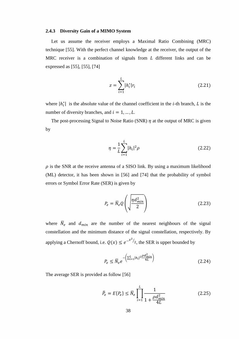
38
2.4.3 Diversity Gain of a MIMO System
Let us assume the receiver employs a Maximal Ratio Combining (MRC)
technique [55]. With the perfect channel knowledge at the receiver, the output of the
MRC receiver is a combination of signals from 𝐿 different links and can be
expressed as [55], [55], [74]
𝑧 = ∑|ℎ𝑖∗|𝑟𝑖
𝐿
𝑖=1
(2.21)
where |ℎ𝑖∗| is the absolute value of the channel coefficient in the 𝑖-th branch, 𝐿 is the
number of diversity branches, and 𝑖 = 1,… , 𝐿.
The post-processing Signal to Noise Ratio (SNR) 𝜂 at the output of MRC is given
by
𝜂 =1
𝐿∑|ℎ𝑖|
2𝜌
𝐿
𝑖=1
(2.22)
𝜌 is the SNR at the receive antenna of a SISO link. By using a maximum likelihood
(ML) detector, it has been shown in [56] and [74] that the probability of symbol
errors or Symbol Error Rate (SER) is given by
𝑃𝑒 = �̅�𝑒𝑄(√𝜂𝑑𝑚𝑖𝑛
2
2) (2.23)
where �̅�𝑒 and 𝑑𝑚𝑖𝑛 are the number of the nearest neighbours of the signal
constellation and the minimum distance of the signal constellation, respectively. By
applying a Chernoff bound, i.e. 𝑄(𝑥) ≤ 𝑒−𝑥2
2⁄ , the SER is upper bounded by
𝑃𝑒 ≤ �̅�𝑒𝑒−(∑ |ℎ𝑖|
2𝜌𝑑𝑚𝑖𝑛2
4𝐿𝐿𝑖=1 )
(2.24)
The average SER is provided as follow [56]
�̅�𝑒 = 𝐸{𝑃𝑒} ≤ �̅�𝑒 ∏1
1 +𝜌𝑑𝑚𝑖𝑛
2
4𝐿
𝐿
𝑖=1
(2.25)
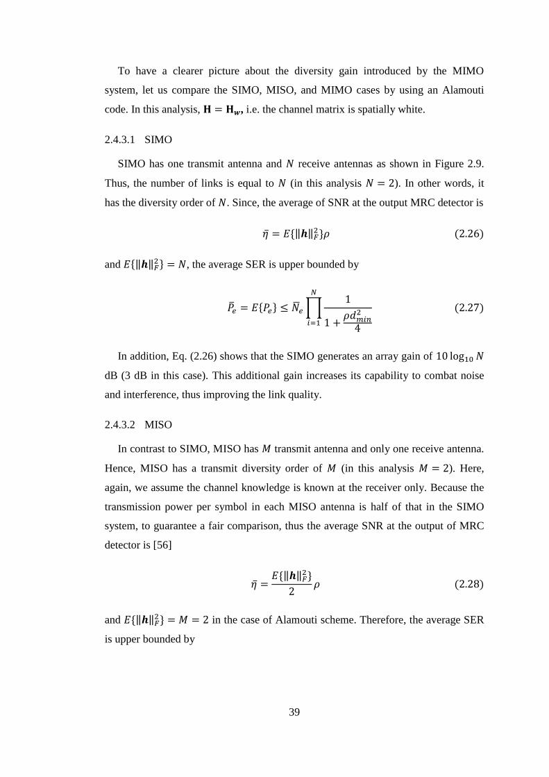
39
To have a clearer picture about the diversity gain introduced by the MIMO
system, let us compare the SIMO, MISO, and MIMO cases by using an Alamouti
code. In this analysis, 𝐇 = 𝐇𝒘, i.e. the channel matrix is spatially white.
2.4.3.1 SIMO
SIMO has one transmit antenna and 𝑁 receive antennas as shown in Figure 2.9.
Thus, the number of links is equal to 𝑁 (in this analysis 𝑁 = 2). In other words, it
has the diversity order of 𝑁. Since, the average of SNR at the output MRC detector is
�̅� = 𝐸{‖𝒉‖𝐹2}𝜌 (2.26)
and 𝐸{‖𝒉‖𝐹2} = 𝑁, the average SER is upper bounded by
�̅�𝑒 = 𝐸{𝑃𝑒} ≤ �̅�𝑒 ∏1
1 +𝜌𝑑𝑚𝑖𝑛
2
4
𝑁
𝑖=1
(2.27)
In addition, Eq. (2.26) shows that the SIMO generates an array gain of 10 log10 𝑁
dB (3 dB in this case). This additional gain increases its capability to combat noise
and interference, thus improving the link quality.
2.4.3.2 MISO
In contrast to SIMO, MISO has 𝑀 transmit antenna and only one receive antenna.
Hence, MISO has a transmit diversity order of 𝑀 (in this analysis 𝑀 = 2). Here,
again, we assume the channel knowledge is known at the receiver only. Because the
transmission power per symbol in each MISO antenna is half of that in the SIMO
system, to guarantee a fair comparison, thus the average SNR at the output of MRC
detector is [56]
�̅� =𝐸{‖𝒉‖𝐹
2}
2𝜌 (2.28)
and 𝐸{‖𝒉‖𝐹2} = 𝑀 = 2 in the case of Alamouti scheme. Therefore, the average SER
is upper bounded by

40
�̅�𝑒 = 𝐸{𝑃𝑒} ≤ �̅�𝑒 ∏1
1 +𝜌𝑑𝑚𝑖𝑛
2
4𝑀
𝑀
𝑖=1
(2.29)
The MISO has no array gain as shown in the Eq. (2.28), hence its SER
performance is inferior to the SIMO.
2.4.3.3 MIMO
As can be seen in Figure 2.9, a 𝑀 × 𝑁 MIMO system can be considered as a
combination of 𝑀 × 𝑁 SISO links. In the case of both 𝑀 and 𝑁 are equal to 2, the
𝐸{‖𝒉‖𝐹2} = 𝑀 × 𝑁 = 4 [56], thus the average SNR at the MRC detector output is
�̅� =𝐸{‖𝒉‖𝐹
2}
2𝜌 = 2𝜌 (2.30)
Figure 2.12 Performance of SIMO, MISO, and MIMO systems compared to the
SISO channel in spatially white channel (𝐇 = 𝐇𝒘) employing an Alamouti scheme,
and a rate of 2 bps/Hz.
Hence, the MIMO average SER is upper bounded by
Diversity gain
Array gain
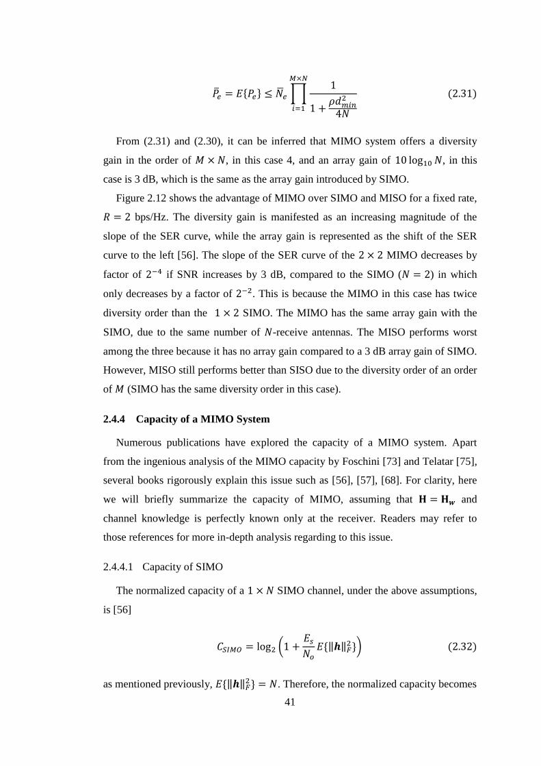
41
�̅�𝑒 = 𝐸{𝑃𝑒} ≤ �̅�𝑒 ∏1
1 +𝜌𝑑𝑚𝑖𝑛
2
4𝑁
𝑀×𝑁
𝑖=1
(2.31)
From (2.31) and (2.30), it can be inferred that MIMO system offers a diversity
gain in the order of 𝑀 × 𝑁, in this case 4, and an array gain of 10 log10 𝑁, in this
case is 3 dB, which is the same as the array gain introduced by SIMO.
Figure 2.12 shows the advantage of MIMO over SIMO and MISO for a fixed rate,
𝑅 = 2 bps/Hz. The diversity gain is manifested as an increasing magnitude of the
slope of the SER curve, while the array gain is represented as the shift of the SER
curve to the left [56]. The slope of the SER curve of the 2 × 2 MIMO decreases by
factor of 2−4 if SNR increases by 3 dB, compared to the SIMO (𝑁 = 2) in which
only decreases by a factor of 2−2. This is because the MIMO in this case has twice
diversity order than the 1 × 2 SIMO. The MIMO has the same array gain with the
SIMO, due to the same number of 𝑁-receive antennas. The MISO performs worst
among the three because it has no array gain compared to a 3 dB array gain of SIMO.
However, MISO still performs better than SISO due to the diversity order of an order
of 𝑀 (SIMO has the same diversity order in this case).
2.4.4 Capacity of a MIMO System
Numerous publications have explored the capacity of a MIMO system. Apart
from the ingenious analysis of the MIMO capacity by Foschini [73] and Telatar [75],
several books rigorously explain this issue such as [56], [57], [68]. For clarity, here
we will briefly summarize the capacity of MIMO, assuming that 𝐇 = 𝐇𝒘 and
channel knowledge is perfectly known only at the receiver. Readers may refer to
those references for more in-depth analysis regarding to this issue.
2.4.4.1 Capacity of SIMO
The normalized capacity of a 1 × 𝑁 SIMO channel, under the above assumptions,
is [56]
𝐶𝑆𝐼𝑀𝑂 = log2 (1 +𝐸𝑠
𝑁𝑜𝐸{‖𝒉‖𝐹
2}) (2.32)
as mentioned previously, 𝐸{‖𝒉‖𝐹2} = 𝑁. Therefore, the normalized capacity becomes
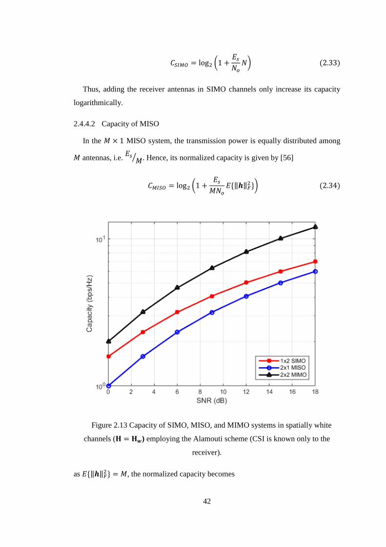
42
𝐶𝑆𝐼𝑀𝑂 = log2 (1 +𝐸𝑠
𝑁𝑜𝑁) (2.33)
Thus, adding the receiver antennas in SIMO channels only increase its capacity
logarithmically.
2.4.4.2 Capacity of MISO
In the 𝑀 × 1 MISO system, the transmission power is equally distributed among
𝑀 antennas, i.e. 𝐸𝑠
𝑀⁄ . Hence, its normalized capacity is given by [56]
𝐶𝑀𝐼𝑆𝑂 = log2 (1 +𝐸𝑠
𝑀𝑁𝑜𝐸{‖𝒉‖𝐹
2}) (2.34)
Figure 2.13 Capacity of SIMO, MISO, and MIMO systems in spatially white
channels (𝐇 = 𝐇𝒘) employing the Alamouti scheme (CSI is known only to the
receiver).
as 𝐸{‖𝒉‖𝐹2} = 𝑀, the normalized capacity becomes
43
𝐶𝑀𝐼𝑆𝑂 = log2 (1 +𝐸𝑠
𝑁𝑜) (2.35)
Note that 𝐶𝑀𝐼𝑆𝑂 is equal to the capacity of SISO link (Shannon’s capacity), and
𝐶𝑀𝐼𝑆𝑂 < 𝐶𝑆𝐼𝑀𝑂.
2.4.4.3 Capacity of MIMO
For an orthogonal MIMO channel, such as in the case of the Alamouti and
Sezginer-Sari schemes, the capacity of the MIMO system is min{M,N} multiplied by
the capacity of the SISO channel [56], namely
𝐶𝑀𝐼𝑀𝑂 = 𝑚𝑖𝑛{𝑀. 𝑁}log2 (1 +𝐸𝑠
𝑁𝑜) (2.36)
The capacity of a 2 × 1 MISO channel is fundamentally the same as the capacity
of SISO channel. From Figure 2.13 it can be seen that the 2 × 2 MIMO system offers
double capacity compared to the capacity of a SISO, while a 1 × 2 SIMO system has
diminishing capacity advantage over MISO when SNR gets higher.
2.4.5 Pros and Cons of MIMO Implementations in WBAN
The big issue in the WBAN design is how to provide highly reliable
communication links between WBAN sensors, the hub and Wireless Access Point
(WAP). The other important issue is how to support high data rate WBAN services
to anticipate the foreseeable bandwidth hungry WBAN applications in the future.
Current IEEE WBAN standard supports the maximum data rate of 15.6 Mbps [21].
With the advent of new health and other WBAN related services, such as
entertainment and military, the need to have a high speed WBAN system is
unavoidable [4], [7].
WBAN channels are rich in scattering which are ideal for MIMO
implementations. MIMO system requires sufficient spacing between antennas, i.e.
spacing between antennas should be equal or greater than the coherence distance.
The coherence distance ensures decorrelation between neighboring channels,
allowing the receiver to extract independent copies of transmitted signals, thus
improving of the system performance. In a rich scattering environment, the
coherence distance is equal to /2 [68]. Thus, in the frequency operation below 1
44
GHz, it is apparently impractical to implement the MIMO scheme in on-body sensors
and the hub. However, in the higher frequency operation, such as in the MB-OFDM
UWB system (center frequency of the sub-bands is between 3.4 GHz – 10.3 GHz, or
the corresponding wavelength is ≃ 3 cm – 9 cm) it is possible to implement the
MIMO scheme, especially for the external link between the hub and the WAP (or in
CM4). The above wavelength requires minimum antenna spacing of only 1.5 cm –
4.5 cm, which is feasible to deploy in the on-body devices, including in the hub.
With the advance of microstrip/patch antenna technologies, it is possible to
manufacture small size WBAN MIMO antennas. However, due to strict health
regulations, particularly in relation to the implant devices and human tissues [4],
[21], implementations of MIMO antennas in the implant WBAN devices seem
unlikely at the moment.
One of the earlier attempts to design and conduct measurements of a receive
diversity technique for UWB WBAN was carried out by Chen, et.al in 2009 [27].
They exploited the antennas of individual WBAN sensors to form a cooperative
communication system. The authors have shown promising results in terms of
diversity gain in the frequency of 5 GHz. Another measurement of a receive diversity
scheme, using two receive antennas in a narrowband WBAN system, was conducted
by Liu, et.al in 2011 at the frequency of 2.47 GHz [28]. This measurement showed a
significant performance improvement due to the diversity gain in the NLOS link, but
showed no effect in the LOS link. Similar measurements, but with a larger number of
receive antenna, and comparable performance results, were presented by Abbasi,
et.al in 2011 [26]. However, none of these measurement campaigns consider
employing a MIMO system. Thus, in this thesis, we investigate the use of MIMO
techniques in the WBAN system to improve the reliability of such systems.
Utilization of MIMO systems in WBAN somewhat increases the complexity in
both the computation and circuitry of the WBAN devices. Considering this fact, we
limit our research on the external link (or CM4) only, where the hub concentrates all
the traffic from WBAN sensors and conveys the traffic to the external WAP. In
addition, the hub is commonly powered by the batteries that require a non-invasive
replacement. Given these constraints, we not only address the reliability of the
WBAN system, but also the energy efficiency of the proposed WBAN system.
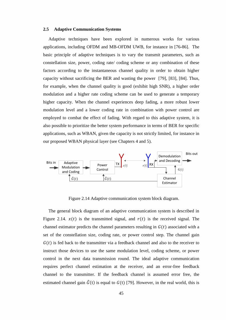
45
2.5 Adaptive Communication Systems
Adaptive techniques have been explored in numerous works for various
applications, including OFDM and MB-OFDM UWB, for instance in [76-86]. The
basic principle of adaptive techniques is to vary the transmit parameters, such as
constellation size, power, coding rate/ coding scheme or any combination of these
factors according to the instantaneous channel quality in order to obtain higher
capacity without sacrificing the BER and wasting the power [79], [83], [84]. Thus,
for example, when the channel quality is good (exhibit high SNR), a higher order
modulation and a higher rate coding scheme can be used to generate a temporary
higher capacity. When the channel experiences deep fading, a more robust lower
modulation level and a lower coding rate in combination with power control are
employed to combat the effect of fading. With regard to this adaptive system, it is
also possible to prioritize the better system performance in terms of BER for specific
applications, such as WBAN, given the capacity is not strictly limited, for instance in
our proposed WBAN physical layer (see Chapters 4 and 5).
Adaptive Modulation and Coding
Power Control
Bits inRXTX
Demodulation and Decoding
Channel Estimator
Bits out
x(t) r(t)
G(t)
𝐺 (𝑡) 𝐺 (𝑡)
Figure 2.14 Adaptive communication system block diagram.
The general block diagram of an adaptive communication system is described in
Figure 2.14. 𝑥(𝑡) is the transmitted signal, and 𝑟(𝑡) is the received signal. The
channel estimator predicts the channel parameters resulting in 𝐺(𝑡) associated with a
set of the constellation size, coding rate, or power control step. The channel gain
𝐺(𝑡) is fed back to the transmitter via a feedback channel and also to the receiver to
instruct those devices to use the same modulation level, coding scheme, or power
control in the next data transmission round. The ideal adaptive communication
requires perfect channel estimation at the receiver, and an error-free feedback
channel to the transmitter. If the feedback channel is assumed error free, the
estimated channel gain 𝐺 (t) is equal to 𝐺(t) [79]. However, in the real world, this is
46
difficult to achieve due to channel estimation errors and the delay in the feedback
channel [84].
One of the early works on adaptive modulation for individual subcarriers of an
OFDM system is [76]. It used a BER metric for controlling adaptive selection.
However, it only considered adaptive modulation without transmit power control and
it did not exploit the diversity of MIMO channels. Keller and Hanzo investigated
adaptive OFDM with the focus on the trade-off between performance and throughput
[77]. They also provided a number of adaptive OFDM techniques and their
performances [78]. Those works mainly focused on gaining a balance between
performance and throughput by employing a limited number of modulation schemes,
i.e. BPSK, QPSK, and 16-QAM, without taking advantage of channel diversity
through MIMO system. The authors in [79] examined a unified adaptive modulation
scheme for a general communication system where the data rate, transmitted power,
and instantaneous BER were varied to maximize spectral efficiency. A cross layer
adaptive modulation scheme to minimize the transmission energy in wireless sensor
networks was proposed in [86]. However, an adaptive modulation and coding
scheme for the MIMO WBAN physical layer has not been examined in the literature.
Therefore, in this thesis we focus on developing adaptive systems for the proposed
STFC MB-OFDM UWB WBAN system.
2.6 Energy Efficiency of a Communication Systems
Traditionally, energy efficiency of a wireless communication system considers
only the transmit power required to radiate the signals toward the receiver. It is due
to the long distance between the transmitter and the receiver resulting in a negligible
amount of power dissipated in the circuitry of both transmitter and receiver,
compared the transmit power level [86], [90]. The advent of short range
communication systems, such as Wireless Sensor Networks (WSN) and WBAN,
means that the traditional approach is no longer valid. The energy consumption of
the circuitry of such systems may be comparable to the transmission energy. In some
cases, particularly when the distance between the transmitter and the receiver is very
small, the energy consumed in the circuitry is more dominant than the energy
required to transmit the signals [87], [88].
Energy efficiency plays a pivotal role in the WBAN design considerations. The
WBAN devices are principally small and operated by batteries. Battery replacement,

47
while possible, is difficult and expensive particularly for the implant devices. As a
consequence, minimization of the energy consumption in the WBAN implementation
is imperative.
The energy efficiency may be measured by the total energy consumption to
transmit the message per bit (TEPB), or the number of bits transmitted per joule of
total energy consumed in the system (NBPE) [88]. The lower TEPB (or higher
NBPE) represents better energy efficiency of a communication system. In the case of
short range communication systems, the total energy consumption to transmit a data
rate 𝑅 consists of the energy consumed in the circuitry of both transmitter and
receiver 𝑃𝐶, and the total RF transmission power 𝑃𝑃𝐴. The circuitry power consists of
the rate-independent power consumption 𝑃, e.g. the power consumed in the
transceiver’s components such as mixer, filter, and ADC/DAC, and the rate-
dependent power consumption in encoders and decoders 𝑃(𝑅). Thus, the total power
consumption is given by
𝑃𝑇𝑜𝑡 = 𝑃𝐶 + 𝑃𝑃𝐴 (2.37)
where
𝑃𝐶 = 𝑃 + 𝑃(𝑅), and
𝑃𝑃𝐴 = (𝜉
𝜂⁄ ) × 𝑃𝑇
where 𝜉 is the peak-to-average power ratio (PAPR), 𝜂 is the drain efficiency of the
power amplifier, and 𝑃𝑇 is the average transmission power. If the maximum data rate
𝑅 is equal to the product of the spectral efficiency of the communication system Γ
and the system bandwidth 𝐵, the energy efficiency in terms of TEPB is then defined
as
𝐸𝐸 =𝑃𝑇𝑜𝑡
Γ𝐵 (
𝐽𝑜𝑢𝑙𝑒
𝑏𝑖𝑡) (2.38)
From Eq.(2.38), note that the energy efficiency is inversely proportional to the
spectral efficiency of a communication system. If 𝑃𝑇𝑜𝑡 is constant, improving one
metric will result in decreasing the other. Thus, the trade-off between these two
contrasting parameters is important in the design considerations, given which
priorities on the design parameters should be weighted. Readers interested in the
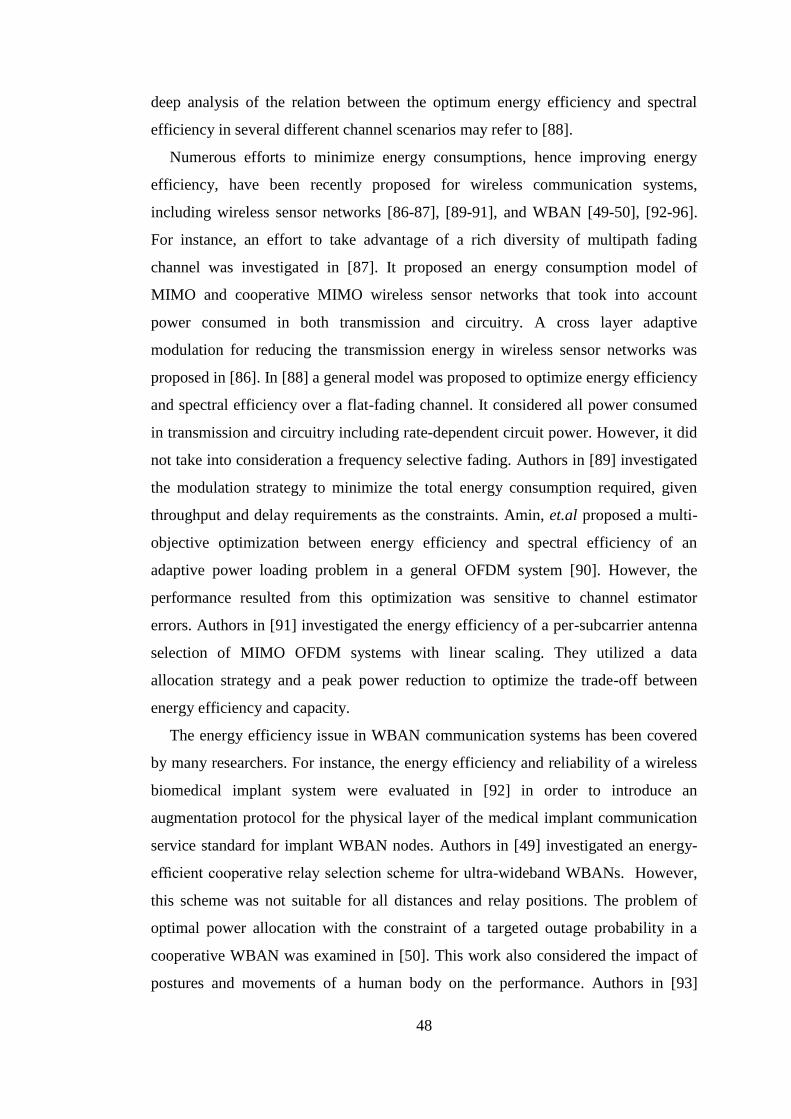
48
deep analysis of the relation between the optimum energy efficiency and spectral
efficiency in several different channel scenarios may refer to [88].
Numerous efforts to minimize energy consumptions, hence improving energy
efficiency, have been recently proposed for wireless communication systems,
including wireless sensor networks [86-87], [89-91], and WBAN [49-50], [92-96].
For instance, an effort to take advantage of a rich diversity of multipath fading
channel was investigated in [87]. It proposed an energy consumption model of
MIMO and cooperative MIMO wireless sensor networks that took into account
power consumed in both transmission and circuitry. A cross layer adaptive
modulation for reducing the transmission energy in wireless sensor networks was
proposed in [86]. In [88] a general model was proposed to optimize energy efficiency
and spectral efficiency over a flat-fading channel. It considered all power consumed
in transmission and circuitry including rate-dependent circuit power. However, it did
not take into consideration a frequency selective fading. Authors in [89] investigated
the modulation strategy to minimize the total energy consumption required, given
throughput and delay requirements as the constraints. Amin, et.al proposed a multi-
objective optimization between energy efficiency and spectral efficiency of an
adaptive power loading problem in a general OFDM system [90]. However, the
performance resulted from this optimization was sensitive to channel estimator
errors. Authors in [91] investigated the energy efficiency of a per-subcarrier antenna
selection of MIMO OFDM systems with linear scaling. They utilized a data
allocation strategy and a peak power reduction to optimize the trade-off between
energy efficiency and capacity.
The energy efficiency issue in WBAN communication systems has been covered
by many researchers. For instance, the energy efficiency and reliability of a wireless
biomedical implant system were evaluated in [92] in order to introduce an
augmentation protocol for the physical layer of the medical implant communication
service standard for implant WBAN nodes. Authors in [49] investigated an energy-
efficient cooperative relay selection scheme for ultra-wideband WBANs. However,
this scheme was not suitable for all distances and relay positions. The problem of
optimal power allocation with the constraint of a targeted outage probability in a
cooperative WBAN was examined in [50]. This work also considered the impact of
postures and movements of a human body on the performance. Authors in [93]
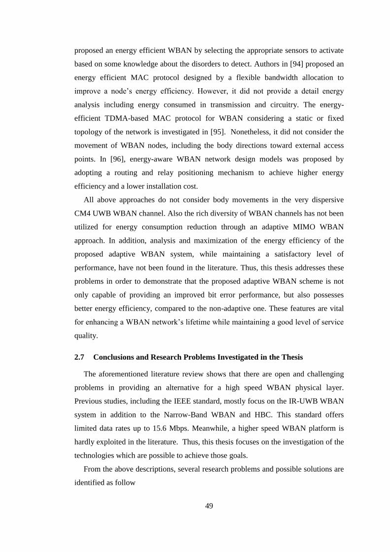
49
proposed an energy efficient WBAN by selecting the appropriate sensors to activate
based on some knowledge about the disorders to detect. Authors in [94] proposed an
energy efficient MAC protocol designed by a flexible bandwidth allocation to
improve a node’s energy efficiency. However, it did not provide a detail energy
analysis including energy consumed in transmission and circuitry. The energy-
efficient TDMA-based MAC protocol for WBAN considering a static or fixed
topology of the network is investigated in [95]. Nonetheless, it did not consider the
movement of WBAN nodes, including the body directions toward external access
points. In [96], energy-aware WBAN network design models was proposed by
adopting a routing and relay positioning mechanism to achieve higher energy
efficiency and a lower installation cost.
All above approaches do not consider body movements in the very dispersive
CM4 UWB WBAN channel. Also the rich diversity of WBAN channels has not been
utilized for energy consumption reduction through an adaptive MIMO WBAN
approach. In addition, analysis and maximization of the energy efficiency of the
proposed adaptive WBAN system, while maintaining a satisfactory level of
performance, have not been found in the literature. Thus, this thesis addresses these
problems in order to demonstrate that the proposed adaptive WBAN scheme is not
only capable of providing an improved bit error performance, but also possesses
better energy efficiency, compared to the non-adaptive one. These features are vital
for enhancing a WBAN network’s lifetime while maintaining a good level of service
quality.
2.7 Conclusions and Research Problems Investigated in the Thesis
The aforementioned literature review shows that there are open and challenging
problems in providing an alternative for a high speed WBAN physical layer.
Previous studies, including the IEEE standard, mostly focus on the IR-UWB WBAN
system in addition to the Narrow-Band WBAN and HBC. This standard offers
limited data rates up to 15.6 Mbps. Meanwhile, a higher speed WBAN platform is
hardly exploited in the literature. Thus, this thesis focuses on the investigation of the
technologies which are possible to achieve those goals.
From the above descriptions, several research problems and possible solutions are
identified as follow

50
The UWB WBAN physical layer requires a robust, power efficient, and
higher speed data rate than the current IR-UWB based standard to deliver an
effective WBAN services. The WBAN physical layer also should be flexible
to comply with different worldwide spectrum arrangements as mentioned
previously, and have low complexity in the realization. These capabilities can
hardly be supported by the existing IR-UWB based WBAN standard.
The MB-OFDM UWB technology is, in our opinion, the best candidate so far
to fulfil the aim in developing an alternative platform for high speed WBAN
applications. This technology offers several advantages. For instance, it offers
the maximum data rate up to 1 Gbps, and has a simple realization by
FFT/IFFT. Moreover, this technology allows the information to be processed
in a much smaller bandwidth, thus turning the frequency selective fading into
the frequency flat fading and reducing the sampling rate of the ADC, which
results in the reduced overall complexity. In addition, it is more flexible in the
spectrum management by turning on and off several tones or channels, hence
improving the worldwide compliance.
Robustness in delivering the WBAN services is a crucial requirement in the
WBAN design. Therefore, given the fact that the WBAN channel is severely
dispersive, this thesis places a great focus on how to improve the robustness
of the WBAN system against the worst channel conditions. In doing so, we
take two techniques into considerations, namely the MIMO and the adaptive
communication system.
MIMO is a powerful technique to improve the system performance, without
sacrificing the bandwidth and timeslot, and requires a relatively simple linear
detection, via MRC and ML decoding (particularly when we use orthogonal
STBC). However, MIMO incurs a moderate increase of complexity (increase
number of antennas). The core scheme in the MIMO is the Space-Time
Coding (STC), which provides the spatial and time diversities. Intuitively, by
employing the MIMO into the MB-OFDM UWB, we can further improve the
performance due to the additional frequency diversity introduced by MB-
OFDM UWB system. Thus, we may obtain spatial, time and frequency
diversities all together at once.
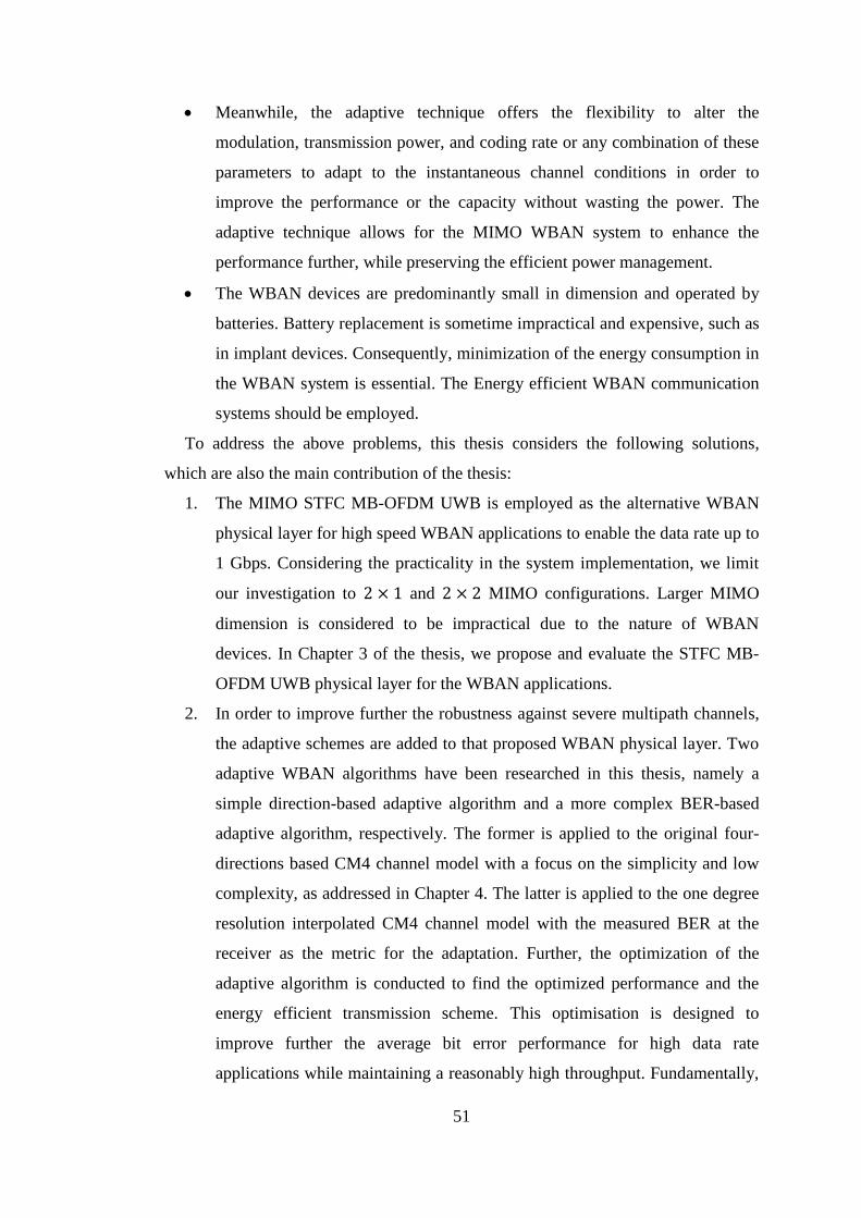
51
Meanwhile, the adaptive technique offers the flexibility to alter the
modulation, transmission power, and coding rate or any combination of these
parameters to adapt to the instantaneous channel conditions in order to
improve the performance or the capacity without wasting the power. The
adaptive technique allows for the MIMO WBAN system to enhance the
performance further, while preserving the efficient power management.
The WBAN devices are predominantly small in dimension and operated by
batteries. Battery replacement is sometime impractical and expensive, such as
in implant devices. Consequently, minimization of the energy consumption in
the WBAN system is essential. The Energy efficient WBAN communication
systems should be employed.
To address the above problems, this thesis considers the following solutions,
which are also the main contribution of the thesis:
1. The MIMO STFC MB-OFDM UWB is employed as the alternative WBAN
physical layer for high speed WBAN applications to enable the data rate up to
1 Gbps. Considering the practicality in the system implementation, we limit
our investigation to 2 × 1 and 2 × 2 MIMO configurations. Larger MIMO
dimension is considered to be impractical due to the nature of WBAN
devices. In Chapter 3 of the thesis, we propose and evaluate the STFC MB-
OFDM UWB physical layer for the WBAN applications.
2. In order to improve further the robustness against severe multipath channels,
the adaptive schemes are added to that proposed WBAN physical layer. Two
adaptive WBAN algorithms have been researched in this thesis, namely a
simple direction-based adaptive algorithm and a more complex BER-based
adaptive algorithm, respectively. The former is applied to the original four-
directions based CM4 channel model with a focus on the simplicity and low
complexity, as addressed in Chapter 4. The latter is applied to the one degree
resolution interpolated CM4 channel model with the measured BER at the
receiver as the metric for the adaptation. Further, the optimization of the
adaptive algorithm is conducted to find the optimized performance and the
energy efficient transmission scheme. This optimisation is designed to
improve further the average bit error performance for high data rate
applications while maintaining a reasonably high throughput. Fundamentally,
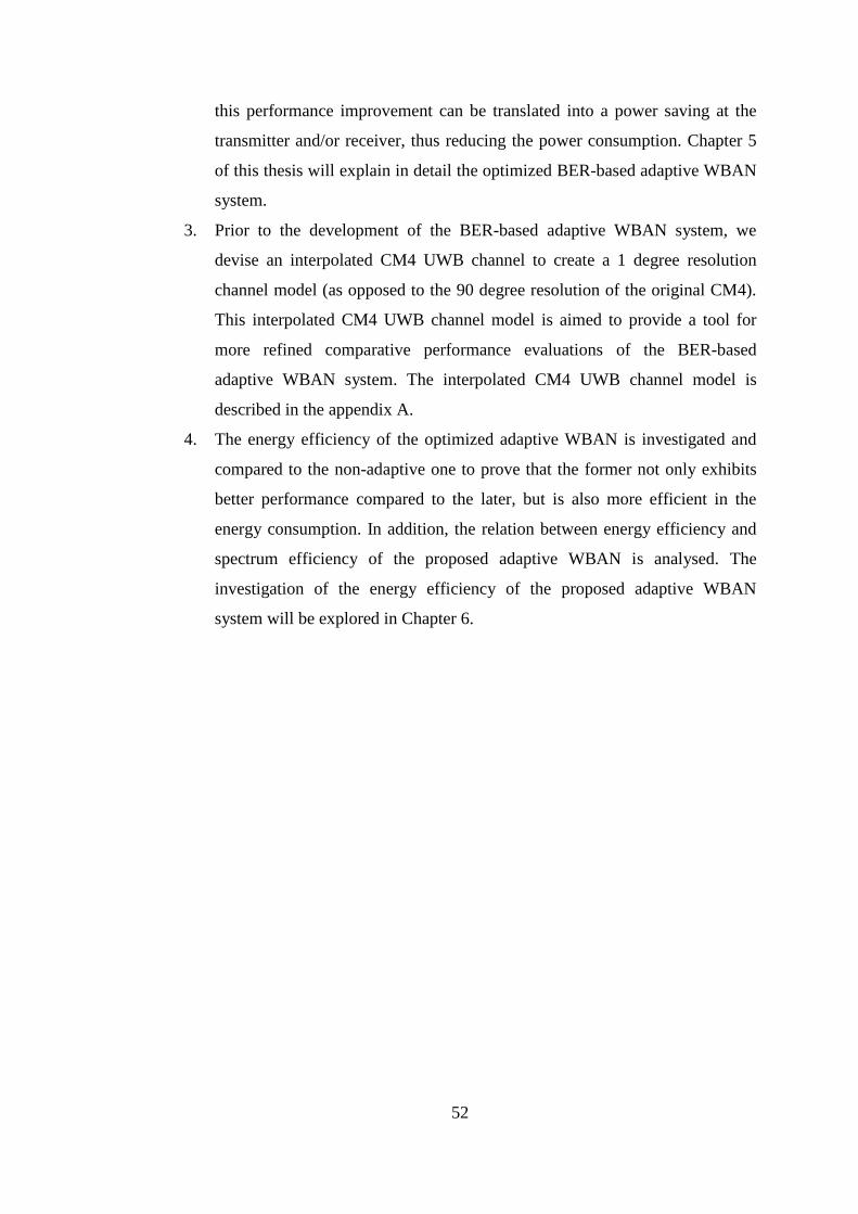
52
this performance improvement can be translated into a power saving at the
transmitter and/or receiver, thus reducing the power consumption. Chapter 5
of this thesis will explain in detail the optimized BER-based adaptive WBAN
system.
3. Prior to the development of the BER-based adaptive WBAN system, we
devise an interpolated CM4 UWB channel to create a 1 degree resolution
channel model (as opposed to the 90 degree resolution of the original CM4).
This interpolated CM4 UWB channel model is aimed to provide a tool for
more refined comparative performance evaluations of the BER-based
adaptive WBAN system. The interpolated CM4 UWB channel model is
described in the appendix A.
4. The energy efficiency of the optimized adaptive WBAN is investigated and
compared to the non-adaptive one to prove that the former not only exhibits
better performance compared to the later, but is also more efficient in the
energy consumption. In addition, the relation between energy efficiency and
spectrum efficiency of the proposed adaptive WBAN is analysed. The
investigation of the energy efficiency of the proposed adaptive WBAN
system will be explored in Chapter 6.
53
CHAPTER 3 PERFORMANCE ANALYSIS OF STFC
MB-OFDM UWB WBAN SYSTEMS FOR HIGH SPEED
WBAN SERVICES
3.1 Introduction
One of the emerging technologies for short range, very high data rate
communication is Multi Band Orthogonal Frequency Division Multiplexing (MB-
OFDM) Ultra-Wideband (UWB), endorsed by the WiMedia Alliance [29]. It
combines the capability of OFDM to flatten the response of the dispersive frequency
selective channel of UWB, while maintaining the benefit of high capacity of UWB. It
is designed to operate at up to 1 Gbps, at low cost and with low power consumption
[29], [46]. Although MB-OFDM UWB is originally designed for Wireless Personal
Area Network (WPAN) applications, but its low transmission power and other
advantages as summarized in Section 2.3, make this technology very attractive to be
a WBAN platform.
Meanwhile, Multiple-Input Multiple-Output (MIMO) technology is proven to be
able to significantly increase the wireless system performance or the capacity for the
same total transmission power and the same system bandwidth [51-58], [67], [70-
73]. Its fundamental mechanism lies on the use of Space-Time Coding (STC) [53-54]
which enables the data to be transmitted by multiple transmit (TX) antennas and
received by multiple receive (RX) antennas. In STCs, signals are coded both in
spatial and temporal domains, for example using the Alamouti scheme or code [55]
or other similar codes [58], [72], [97-100]. With regard to the STC, we use the word
code or scheme alternately in this Thesis. The Alamouti code is designed for
frequency flat fading, and is capable of providing full rate and full diversity for up to
two transmit and two receive antennas. As a result, it enhances the diversity order
and improves the link quality and capacity.
However, its direct application for a very dispersive UWB WBAN channel may
not be suitable. Therefore, in order to attain higher data rates and capitalize on the
rich dispersion of UWB WBAN channels, further addition of the frequency domain
processing in STC can be deployed. So, the process becomes Space-Time-Frequency
Coding (STFC). Readers may refer to [23], [30], and [101-102] for more details

54
about STFCs and its comparison with STC. It is intuitive that a STFC MB-OFDM
UWB system may provide better link performance, and higher data rate and system
capacity.
There has been relatively intensive research on MIMO OFDM systems in past
years such as in [101-102], and on MIMO MB-OFDM UWB systems [23], [30], [97-
99], [103-104]. These systems were only implemented in the frequency selective
channel [101], Rician or Rayleigh fading channel [102], Nakagami-m fading channel
[23], and UWB WPAN channel [30], [97-99], [103-104], rather than UWB WBAN
channel. Authors in [30] proposed the combination of MIMO, STFC, and MB-
OFDM UWB, referred to as the STFC MB-OFDM UWB system, for general WPAN
channels. However, to the best of our knowledge, the performance analysis of a
STFC MB-OFDM UWB system implemented in the proposed IEEE WBAN
channels [13] is still missing.
It is important to highlight the main differences between UWB channel models
for Wireless Personal Area Networks (WPANs) [13] with the aforementioned UWB
WBAN channel. The WPAN channel models are based on the Saleh-Valenzuela
model and do not consider the effect of the human body, while the UWB WBAN
channel models do. It is clearly shown in [13] that due to the shadowing effect of the
human body, the UWB WBAN channel produces a larger amplitude standard
deviation 𝜎 and a much greater exponential decay factor Γ compared to the UWB
WPAN channel. Moreover, Γ varies significantly for different body directions with
respect to the transmitter in the case of CM4 over the UWB WBAN channel.
Therefore, it is necessary to investigate the performance of the MIMO MB-OFDM
UWB system over these WBAN channels.
The WBAN designs primarily focus on critical issues such as capacity,
reliability, dimension, and energy efficiency to suit their practical implementations.
In order to address these challenges in WBAN implementations, this chapter
proposes for the first time the STFC MB-OFDM UWB as the physical layer for high
speed (up to 1 Gbps) WBAN in addition to the IEEE IR-UWB WBAN standard. This
proposal combines an MB-OFDM UWB based technology with Multiple Input
Multiple Output (MIMO) technique to capture and maximize the advantages of a rich
diversity environment of WBAN channels. The evaluation of this proposed physical
layer was done in CM3 and CM4 UWB WBAN channel. The results show that the
55
proposed STFC MB-OFDM UWB scheme substantially outperforms the
conventional MB-OFDM UWB system for WBAN physical layer, in the order of 4.9
dB and 10.2 dB for 2I1O and 2I2O configurations, respectively. This means that the
STFC MB-OFDM UWB is a strong candidate for a high speed WBAN system.
The contributions of this chapter are as follows
Analysis of the feasibility of STFC MB-OFDM UWB as a physical layer
for high speed WBAN,
Investigation and analysis of the STFC MB-OFDM UWB system model,
Evaluation of the performance of the proposed STFC MB-OFDM UWB
WBAN system in the CM3 and CM4 UWB WBAN channels via
simulations,
Investigation and analysis of the influence of body directions (due to
human body movements) on the system performances, and
The recognition of the dependence of the system performance to different
body directions (the direction of the receiver placed on the surface of the
body with respect to the fixed external transceiver) due to human body
movements.
The contents of this chapter were published in [105] and partly in [106].
This chapter is organized as follows. Section 3.2 highlights requirements of the
physical layer of high speed WBAN. Section 3.3 analyses the proposed system
model. The investigation of the performance of STFC MB-OFDM UWB WBAN
system with the M-PSK modulation scheme in the CM3 and CM4 UWB WBAN
channel models is presented in Section 3.4. Finally, Section 3.5 concludes this
chapter.
3.2 High Speed WBAN PHY Layer Requirements
UWB WBAN operates in a common band of 3.1 – 10.6 GHz. These bands are
shared with other applications such as satellite communications and other UWB
communications system [4]. Therefore UWB WBAN must be able to co-exist with
other wireless communication systems.
Human body movements such as walking, laying, kneeling down, moving arms
and legs, will randomly vary the channel conditions between nodes [13], [34-35],
[39]. These channel variations could lead to unpredictable changes of channel
behavior, which possibly result in the degradation of the quality of communications

56
between nodes. Furthermore, the interference from nearby UWB WBAN users may
arise when users move towards each other in a multi user environment. Therefore, a
WBAN physical layer should have a capability to mitigate the interference from
other users or in other words, it should have an inherent high interference-resistant
mechanism.
As such, we can summarize the minimum requirements of WBAN [4], [7] as
follows
1. Limited ranges from few centimetres – 5 metres,
2. Small size and lightweight devices,
3. Capable to co-exist with other wireless technologies,
4. Interference resistance from other wireless communication systems,
5. Robust and secure data transmission,
6. Support scalable data rates from few kbps to tens of Mbps,
7. High capacity in order to be able to support foreseeable future bandwidth-
hungry applications, and
8. Extremely low power consumption and high energy efficiency.
In order to fulfil the requirements of the WBAN physical layer as mentioned
above, we propose the combination of STFC and MB-OFDM UWB (referred to as
STFC MB-OFDM UWB WBAN), as a high speed physical layer for WBAN. The
requirements 1-8 can be addressed by the combination of the MB-OFDM UWB
technology and the STFC-MIMO technique [29], [30]. The following section
describes our proposed STFC MB-OFDM UWB WBAN platform in detail.
3.3 The Proposed STFC MB-OFDM UWB Platform
This Section proposes the implementation of STFC MB-OFDM UWB in the
WBAN channels using the Alamouti code.
3.3.1 The Channel Models
For the purpose of investigation, we only consider the body-to-body (CM3 UWB
WBAN) channel and body-to-external (CM4 UWB WBAN) channel. The
characteristics of CM3 UWB WBAN are described in Section 2.2.4.3, and
characteristics of CM4 UWB WBAN are explained in Section 2.2.4.4.
It is important to note the unique characteristic of the CM4 UWB WBAN
channel model as appeared in Table 2.5, that the worst link is corresponding to the
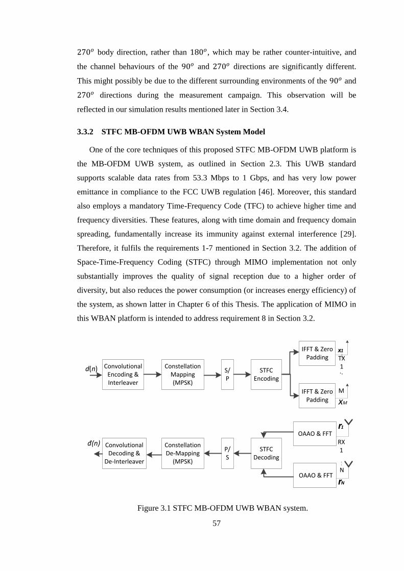
57
270𝑜 body direction, rather than 180𝑜, which may be rather counter-intuitive, and
the channel behaviours of the 90𝑜 and 270𝑜 directions are significantly different.
This might possibly be due to the different surrounding environments of the 90𝑜 and
270𝑜 directions during the measurement campaign. This observation will be
reflected in our simulation results mentioned later in Section 3.4.
3.3.2 STFC MB-OFDM UWB WBAN System Model
One of the core techniques of this proposed STFC MB-OFDM UWB platform is
the MB-OFDM UWB system, as outlined in Section 2.3. This UWB standard
supports scalable data rates from 53.3 Mbps to 1 Gbps, and has very low power
emittance in compliance to the FCC UWB regulation [46]. Moreover, this standard
also employs a mandatory Time-Frequency Code (TFC) to achieve higher time and
frequency diversities. These features, along with time domain and frequency domain
spreading, fundamentally increase its immunity against external interference [29].
Therefore, it fulfils the requirements 1-7 mentioned in Section 3.2. The addition of
Space-Time-Frequency Coding (STFC) through MIMO implementation not only
substantially improves the quality of signal reception due to a higher order of
diversity, but also reduces the power consumption (or increases energy efficiency) of
the system, as shown latter in Chapter 6 of this Thesis. The application of MIMO in
this WBAN platform is intended to address requirement 8 in Section 3.2.
TX 1 . .
M
RX 1
N
d(n)
x1
Convolutional Encoding & Interleaver
Constellation Mapping(MPSK)
S/P
STFC Encoding
IFFT & Zero Padding
IFFT & Zero Padding
OAAO & FFT
OAAO & FFTrN
r1
STFC Decoding
P/S
Constellation De-Mapping
(MPSK)
Convolutional Decoding &
De-Interleaver
đ(n)
xM
Figure 3.1 STFC MB-OFDM UWB WBAN system.
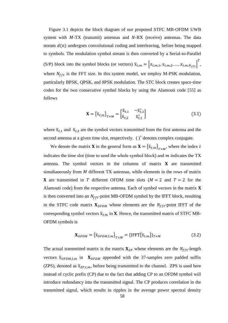
58
Figure 3.1 depicts the block diagram of our proposed STFC MB-OFDM UWB
system with 𝑀-TX (transmit) antennas and 𝑁-RX (receive) antennas. The data
stream 𝑑(𝑛) undergoes convolutional coding and interleaving, before being mapped
to symbols. The modulation symbol stream is then converted by a Serial-to-Parallel
(S/P) block into the symbol blocks (or vectors) x̅𝑡,𝑚 = [𝑥𝑡,𝑚,1, 𝑥𝑡,𝑚,2, … , 𝑥𝑡,𝑚,𝑁𝑓𝑓𝑡]𝑇
,
where 𝑁𝑓𝑓𝑡 is the FFT size. In this system model, we employ M-PSK modulation,
particularly BPSK, QPSK, and 8PSK modulation. The STC block creates space-time
codes for the two consecutive symbol blocks by using the Alamouti code [55] as
follows
𝐗 = {x̅𝑡,𝑚}𝑇×𝑀
= [x̅𝑡,1 −x̅𝑡,2
∗
x̅𝑡,2 x̅𝑡,1∗ ] (3.1)
where x̅𝑡,1 and x̅𝑡,2 are the symbol vectors transmitted from the first antenna and the
second antenna at a given time slot, respectively. ( )* denotes complex conjugate.
We denote the matrix 𝐗 in the general form as 𝐗 = {x̅𝑡,𝑚}𝑇×𝑀
, where the index 𝑡
indicates the time slot (time to send the whole symbol block) and 𝑚 indicates the TX
antenna. The symbol vectors in the columns of matrix 𝐗 are transmitted
simultaneously from 𝑀 different TX antennas, while elements in the rows of matrix
𝐗 are transmitted in 𝑇 different OFDM time slots (𝑀 = 2 and 𝑇 = 2 for the
Alamouti code) from the respective antenna. Each of symbol vectors in the matrix 𝐗
is then converted into an 𝑁𝑓𝑓𝑡-point MB-OFDM symbol by the IFFT block, resulting
in the STFC code matrix 𝐗𝑂𝐹𝐷𝑀 whose elements are the 𝑁𝑓𝑓𝑡-point IFFT of the
corresponding symbol vectors x̅𝑡,𝑚 in 𝐗. Hence, the transmitted matrix of STFC MB-
OFDM symbols is
𝐗𝑂𝐹𝐷𝑀 = {x̅𝑂𝐹𝐷𝑀,𝑡,𝑚}𝑇×𝑀
= {IFFT{x̅𝑡,𝑚}}𝑇×𝑀 (3.2)
The actual transmitted matrix is the matrix 𝐗𝑍𝑃 whose elements are the 𝑁𝑓𝑓𝑡-length
vectors x̅𝑂𝐹𝐷𝑀,𝑡,𝑚 in 𝐗𝑂𝐹𝐷𝑀 appended with the 37-samples zero padded suffix
(ZPS), denoted as x̅𝑍𝑃,𝑡,𝑚, before being transmitted to the channel. ZPS is used here
instead of cyclic prefix (CP) due to the fact that adding CP to an OFDM symbol will
introduce redundancy into the transmitted signal. The CP produces correlation in the
transmitted signal, which results in ripples in the average power spectral density
59
(PSD) of MB-OFDM UWB system that could be as high as 1.5 dB [30]. This
problem might force power back off at the MB-OFDM UWB transmitter, hence
reducing the transmission range. When a ZPS is used, ripples in the PSD can be
reduced significantly, thus the power back off problem at the transmitter can be
mitigated and the system can achieve the maximum possible range. This means
𝐗𝑍𝑃 = {x̅𝑍𝑃,𝑡,𝑚}𝑇×𝑀
(3.3)
The channels between M TX antennas and N RX antennas are defined as the
channel matrix 𝐇
𝐇 = [h̅1,1 ⋯ h̅𝑀,1
⋮ ⋱ ⋮h̅1,𝑁 ⋯ h̅𝑀,𝑁
] (3.4)
where h̅𝑚,𝑛 is the channel coefficient vector between the 𝑚-th TX antenna, for 𝑚 =
1,2, … ,𝑀, and the 𝑛-th RX antenna, 𝑛 = 1,2, … ,𝑁, containing 𝑙 multipaths. The
distribution and parameters of h̅𝑚,𝑛 are determined by Eq. (2.2) and Table 2.4 for
CM3 UWB WBAN channel and by Eq. (2.3) and Table 2.5 for CM4 UWB WBAN
channel.
In the receiver, the received signals at the 𝑛-th RX antenna during the 𝑡-th
transmitted OFDM symbol duration is computed as
r̅𝑡,𝑛 = ∑(x̅𝑍𝑃,𝑡,𝑚 ⋆ h̅𝑚,𝑛) + n̅𝑡,𝑛
𝑀
𝑚=1
(3.5)
where (⋆) denotes the linear convolution, x̅𝑍𝑃,𝑡,𝑚 is the 𝑡-th transmitted MB-OFDM
symbol including ZPS from the 𝑚-th TX antenna, and n̅𝑡,𝑛 is the zero mean Additive
White Gaussian Noise (AWGN) vector. The ZPS is removed by an Overlap-And-
Add-Operation (OAAO) prior to the FFT operation. The OAAO operates by taking
(𝑁𝑓𝑓𝑡 + 1) to (𝑁𝑓𝑓𝑡 + 𝑁𝑍𝑃𝑆) samples from the received symbols r̅𝑡,𝑛 , and adding
them to the first 𝑁𝑍𝑃𝑆 samples of the received symbols r̅𝑡,𝑛. Then, the first 𝑁𝑓𝑓𝑡
symbol will be used to decode the transmitted symbol, creating a circular
convolution between the transmitted OFDM symbols before ZPS addition and the
channel h̅𝑚𝑛. Hence, after performing OAAO, we have
60
r̅𝑂𝐹𝐷𝑀,𝑡,𝑛 = ∑ x̅𝑂𝐹𝐷𝑀,𝑡,𝑚
𝑀
𝑚=1
⊛ h̅𝑚,𝑛 + n̅𝑡,𝑛 (3.6)
where (⊛) denote circular convolution. Using the same approach as in [30], after the
FFT block, the input signals of the STFC decoder is calculated as follow
�̅�𝑡,𝑛 = ∑ x̅𝑡,𝑚 • �̅�𝑚,𝑛
𝑀
𝑚=1
+ �̅�𝑡,𝑛 (3.7)
where (•) denotes the dot (Hardamard) product between the two vectors, �̅�𝑡,𝑛 =
FFT(r̅𝑂𝐹𝐷𝑀,𝑡,𝑛 ) = [𝔯𝑚,𝑛,1 , … , 𝔯𝑚,𝑛,𝑁𝑓𝑓𝑡 ]
𝑇
, x̅𝑡,𝑚 is the original modulation symbols,
�̅�𝑚,𝑛 = FFT(h̅𝑚𝑛) = [ℏ𝑚,𝑛,1 , … , ℏ𝑚,𝑛,𝑁𝑓𝑓𝑡 ]𝑇
, and �̅�𝑡,𝑛 = FFT(n̅𝑡,𝑛). Denote ℛ =
{�̅�𝑡,𝑛}𝑇×𝑁 to be the received signals matrix after FFT, ℋ = {�̅�𝑚,𝑛}𝑀×𝑁
to be the
channel response matrix, and 𝒩 = {�̅�𝑡,𝑛}𝑇×𝑁 is the matrix of noise. Then we can re-
write Eq. (3.7) as
ℛ = 𝐗 ∘ ℋ + 𝒩 (3.8)
where (◦) denotes the multiplication operation between two matrices 𝐗 = {x̅𝑡,𝑚}𝑇×𝑀
and ℋ = {�̅�𝑚,𝑛}𝑀×𝑁 whose elements x̅𝑡,𝑚 and �̅�𝑚,𝑛 are a 𝑁𝑓𝑓𝑡-length vectors, such
that the (t, n)-th element of the resulting matrix ℛ is a 𝑁𝑓𝑓𝑡-length column vectors
∑ x̅𝑡,𝑚 • �̅�𝑚,𝑛𝑀𝑚=1 [30].
We use the same approach as [30] for decoding the signals and detecting the
transmitted data using Maximum Likelihood (ML) detection. The detected vectors
are decided by
{x̃̅𝑡,𝑚} = arg min{x̅𝑡,𝑚}
‖ℛ − 𝐗 ∘ ℋ‖𝐹2 (3.9)
Since the matrix 𝐗 preserves its orthogonality in the similar manner as in a
conventional STBC MIMO system, the STFC MB-OFDM UWB system can also
employ a simple linear decoding process. For simplicity, we can omit the time index
t. Hence in the 2I1O configuration with M-PSK modulation, we have the following
decoding metrics
61
x̃̅1 = arg minx̅∈𝒞𝑁𝐷
‖[|(�̅�1∗ • �̅�1 + �̅�2 • �̅�2
∗) − x̅|.∧ 2]‖𝐹2
x̃̅2 = arg minx̅∈𝒞𝑁𝐷
‖[|(�̅�2∗ • �̅�1 − �̅�1 • �̅�2
∗) − x̅|.∧ 2]‖𝐹2 (3.10)
where x̅.∧ 2 denotes the element-wise power-2 operation of a matrix or a vector x̅, 𝑁𝐷
is number of data subcarriers (𝑁𝐷 = 100, according to the WiMedia standard [29]),
and 𝒞𝑁𝐷denotes the ND-dimensional complex space of the transmitted vector x̅. For
the 2I2O, the decoding metrics are
x̃̅1 = arg minx̅∈𝒞𝑁𝐷
‖[|(�̅�11∗ • �̅�11 + �̅�21 • �̅�21
∗ + �̅�12∗ • �̅�12 + �̅�22 • �̅�22
∗ ) − x̅|.∧ 2]‖𝐹2
x̃̅2 = arg minx̅∈𝒞𝑁𝐷
‖[|(�̅�21∗ • �̅�11 − �̅�11 • �̅�21
∗ + �̅�22∗ • �̅�12 − �̅�12 • �̅�22
∗ ) − x̅|.∧ 2]‖𝐹2 (3.11)
More importantly, each data point in an MB-OFDM symbol can be decoded
separately rather than jointly [30], thus the decoding process is significantly
simplified. In particular, the decoding metric of each data symbol at the 𝑘-th
subcarrier, for 𝑘 = 1,… ,𝑁𝐷, in the MB-OFDM symbols are
�̃�1,𝑘 = arg min𝑥1,𝑘∈𝒞
[|(ℏ1,𝑘∗ 𝔯1,𝑘 + ℏ2,𝑘𝔯2,𝑘
∗ ) − 𝑥1,𝑘|2]
�̃�2,𝑘 = arg min𝑥2,𝑘∈𝒞
[|(ℏ2,𝑘∗ 𝔯1,𝑘 − ℏ1,𝑘𝔯2,𝑘
∗ ) − 𝑥1,𝑘|2] (3.12)
for the 2I1O configuration, and
�̃�1,𝑘 = arg min𝑥1,𝑘∈𝒞
[|∑(ℏ1,𝑛,𝑘∗ 𝔯1,𝑛,𝑘 + ℏ2,𝑛,𝑘𝔯2,𝑛,𝑘
∗ )
2
𝑛=1
− 𝑥1,𝑘|
2
]
�̃�2,𝑘 = arg min𝑥2,𝑘∈𝒞
[|∑(ℏ2,𝑛,𝑘∗ 𝔯1,𝑛,𝑘 − ℏ1,𝑛,𝑘𝔯2,𝑛,𝑘
∗ )
2
𝑛=1
− 𝑥2,𝑘|
2
] (3.13)
for the 2I2O configuration. Generalization for the case of 𝑀-TX and 𝑁-RX antennas
is straightforward. For the full account on the general STFC MB-OFDM UWB
system, the reader may refer to [30].
62
3.4 Simulation Results.
The performance in terms of BER of the proposed system is assessed by Monte-
Carlo simulations for three different configurations, those are Single-Input Single-
Output (SISO), 2I1O and 2I2O, assuming perfect channel state information be
available at the receiver. The total transmitted power from all TX antennas is kept
equal at all times in all configurations, in order to fairly compare their performances.
The channel conditions and their associated parameters are described in Chapter 2.
Moreover, in the MIMO MB-OFDM UWB channel, the frequency selective channel
is turned into frequency flat fading channel (c.f. Section 2.3). Therefore, channel
coefficients are assumed to be constant during two consecutive OFDM symbols, that
is during each Alamouti STFC block, but random between consecutive Alamouti
STFC blocks. The channel realizations are simulated by the MATLAB program
enclosed in the appendix of IEEE 802.15.6 channel modelling subcommittee final
document [13]. The other simulation parameters are listed in Table 3.1. The number
of the OFDM symbols sent in each run of simulation is 50,000 in order to get at least
100 bit errors in every 𝐸𝑏/𝑁𝑜 point.
We compare the system performance for MPSK modulations in the CM3 UWB
WBAN and CM4 UWB WBAN channel models. MPSK modulation is considered
here because it is generally one of the most efficient and most powerful modulation
schemes [74], and particularly the QPSK is one of the modulation schemes employed
in MB-OFDM UWB standard [29]. Due to the increased complexity and worsening
performance in the higher M-level PSK as manifest in this investigation, thus we
only compare three lower MPSK modulations, these are BPSK, QPSK, and 8-PSK.
With regard to the simulation of body-to-external link connecting the Hub and
the WAP (CM4 UWB WBAN channel), we use only QPSK modulation to simulate
the effect of body directions in both MIMO (2I1O and 2I2O) configurations. The
QPSK is used here because of its better performance compared to the higher level
MPSK, and QPSK has twice the spectral efficiency of BPSK [74]. In this simulation,
the transmitter is fixed near to the wall, while the receiver is placed on body and
varied for four different positions (c.f. Figure 2.5). These body directions are the
result of body movement, creating a possible LOS and NLOS links between
transmitter and receiver on body due to the effect of body shadowing. In this channel
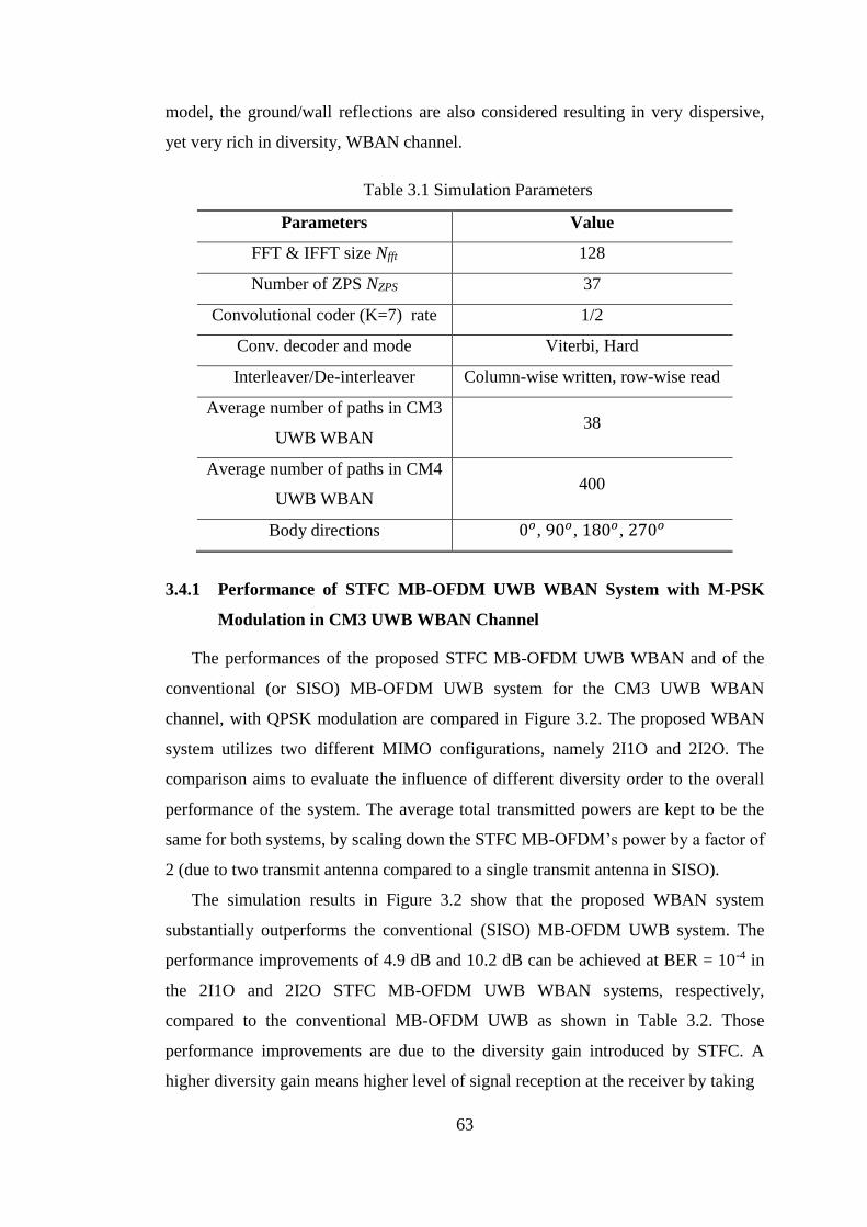
63
model, the ground/wall reflections are also considered resulting in very dispersive,
yet very rich in diversity, WBAN channel.
Table 3.1 Simulation Parameters
Parameters Value
FFT & IFFT size Nfft 128
Number of ZPS NZPS 37
Convolutional coder (K=7) rate 1/2
Conv. decoder and mode Viterbi, Hard
Interleaver/De-interleaver Column-wise written, row-wise read
Average number of paths in CM3
UWB WBAN 38
Average number of paths in CM4
UWB WBAN 400
Body directions 0𝑜, 90𝑜, 180𝑜, 270𝑜
3.4.1 Performance of STFC MB-OFDM UWB WBAN System with M-PSK
Modulation in CM3 UWB WBAN Channel
The performances of the proposed STFC MB-OFDM UWB WBAN and of the
conventional (or SISO) MB-OFDM UWB system for the CM3 UWB WBAN
channel, with QPSK modulation are compared in Figure 3.2. The proposed WBAN
system utilizes two different MIMO configurations, namely 2I1O and 2I2O. The
comparison aims to evaluate the influence of different diversity order to the overall
performance of the system. The average total transmitted powers are kept to be the
same for both systems, by scaling down the STFC MB-OFDM’s power by a factor of
2 (due to two transmit antenna compared to a single transmit antenna in SISO).
The simulation results in Figure 3.2 show that the proposed WBAN system
substantially outperforms the conventional (SISO) MB-OFDM UWB system. The
performance improvements of 4.9 dB and 10.2 dB can be achieved at BER = 10-4 in
the 2I1O and 2I2O STFC MB-OFDM UWB WBAN systems, respectively,
compared to the conventional MB-OFDM UWB as shown in Table 3.2. Those
performance improvements are due to the diversity gain introduced by STFC. A
higher diversity gain means higher level of signal reception at the receiver by taking

64
Figure 3.2 Performance comparison of the STFC MB-OFDM UWB and
conventional (SISO) MB-OFDM systems in CM3 UWB WBAN channel.
Table 3.2 𝐸𝑏/𝑁𝑜 required to achieve BER = 10-4 in STFC MB-OFDM UWB and
MB-OFDM UWB in CM3 UWB WBAN Channel
Scheme 𝐸𝑏/𝑁𝑜 (dB) Improvement (dB) compared to
MB-OFDM UWB
SISO MB-OFDM UWB 15.1 -
2I1O MB-OFDM UWB 10.2 4.9
2I2O MB-OFDM UWB 4.9 10.2
advantage of combining more multipath signals. Therefore, the 2I2O configuration
achieves a 5.3 dB better performance at BER= 10-4, compared to 211O configuration.
In addition to the diversity gain, the 2I2O also provides 3 dB array gain (c.f. Eq.
(2.30)), while the 2I1O offers no array gain (c.f. Eq. (2.28)). The combination of
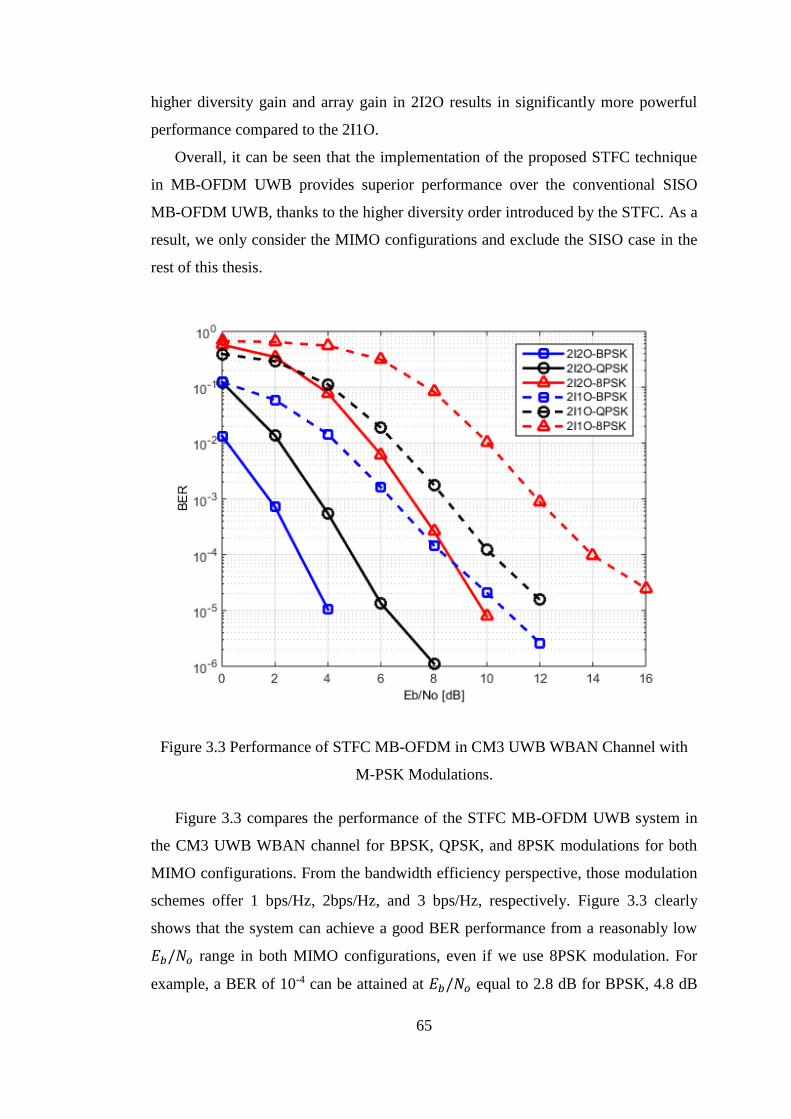
65
higher diversity gain and array gain in 2I2O results in significantly more powerful
performance compared to the 2I1O.
Overall, it can be seen that the implementation of the proposed STFC technique
in MB-OFDM UWB provides superior performance over the conventional SISO
MB-OFDM UWB, thanks to the higher diversity order introduced by the STFC. As a
result, we only consider the MIMO configurations and exclude the SISO case in the
rest of this thesis.
Figure 3.3 Performance of STFC MB-OFDM in CM3 UWB WBAN Channel with
M-PSK Modulations.
Figure 3.3 compares the performance of the STFC MB-OFDM UWB system in
the CM3 UWB WBAN channel for BPSK, QPSK, and 8PSK modulations for both
MIMO configurations. From the bandwidth efficiency perspective, those modulation
schemes offer 1 bps/Hz, 2bps/Hz, and 3 bps/Hz, respectively. Figure 3.3 clearly
shows that the system can achieve a good BER performance from a reasonably low
𝐸𝑏/𝑁𝑜 range in both MIMO configurations, even if we use 8PSK modulation. For
example, a BER of 10-4 can be attained at 𝐸𝑏/𝑁𝑜 equal to 2.8 dB for BPSK, 4.8 dB
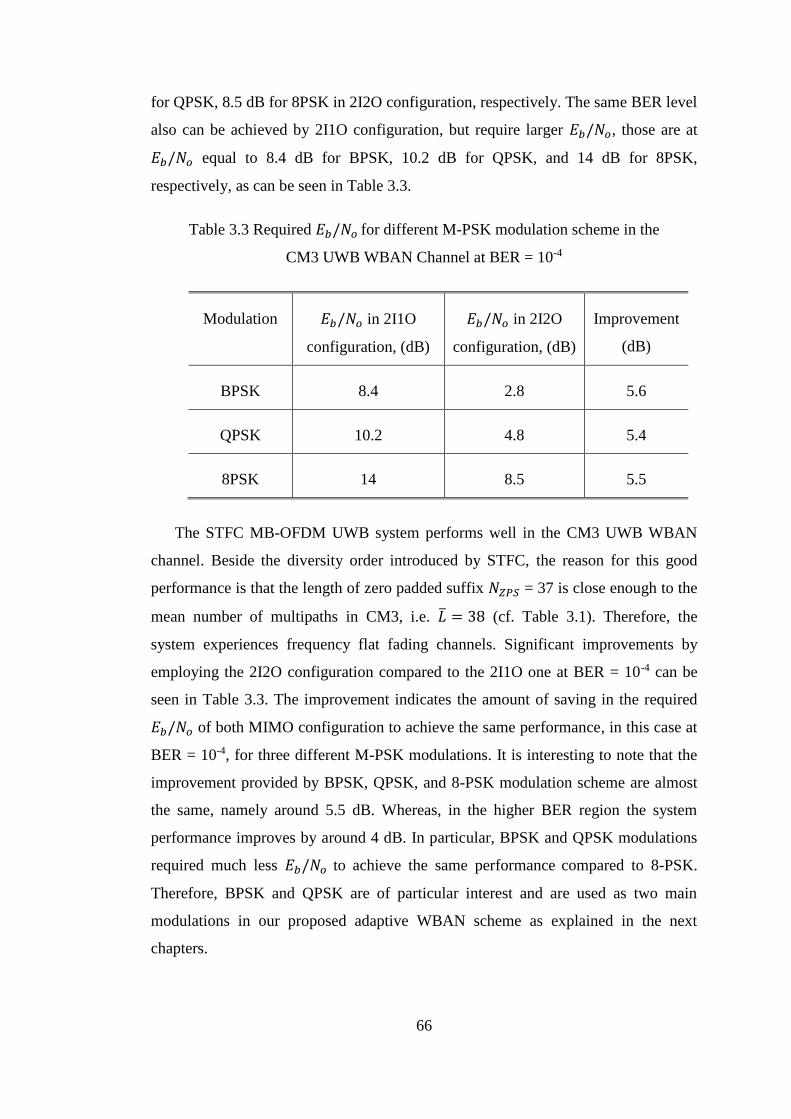
66
for QPSK, 8.5 dB for 8PSK in 2I2O configuration, respectively. The same BER level
also can be achieved by 2I1O configuration, but require larger 𝐸𝑏/𝑁𝑜, those are at
𝐸𝑏/𝑁𝑜 equal to 8.4 dB for BPSK, 10.2 dB for QPSK, and 14 dB for 8PSK,
respectively, as can be seen in Table 3.3.
Table 3.3 Required 𝐸𝑏/𝑁𝑜 for different M-PSK modulation scheme in the
CM3 UWB WBAN Channel at BER = 10-4
Modulation 𝐸𝑏/𝑁𝑜 in 2I1O
configuration, (dB)
𝐸𝑏/𝑁𝑜 in 2I2O
configuration, (dB)
Improvement
(dB)
BPSK 8.4 2.8 5.6
QPSK 10.2 4.8 5.4
8PSK 14 8.5 5.5
The STFC MB-OFDM UWB system performs well in the CM3 UWB WBAN
channel. Beside the diversity order introduced by STFC, the reason for this good
performance is that the length of zero padded suffix 𝑁𝑍𝑃𝑆 = 37 is close enough to the
mean number of multipaths in CM3, i.e. �̅� = 38 (cf. Table 3.1). Therefore, the
system experiences frequency flat fading channels. Significant improvements by
employing the 2I2O configuration compared to the 2I1O one at BER = 10-4 can be
seen in Table 3.3. The improvement indicates the amount of saving in the required
𝐸𝑏/𝑁𝑜 of both MIMO configuration to achieve the same performance, in this case at
BER = 10-4, for three different M-PSK modulations. It is interesting to note that the
improvement provided by BPSK, QPSK, and 8-PSK modulation scheme are almost
the same, namely around 5.5 dB. Whereas, in the higher BER region the system
performance improves by around 4 dB. In particular, BPSK and QPSK modulations
required much less 𝐸𝑏/𝑁𝑜 to achieve the same performance compared to 8-PSK.
Therefore, BPSK and QPSK are of particular interest and are used as two main
modulations in our proposed adaptive WBAN scheme as explained in the next
chapters.
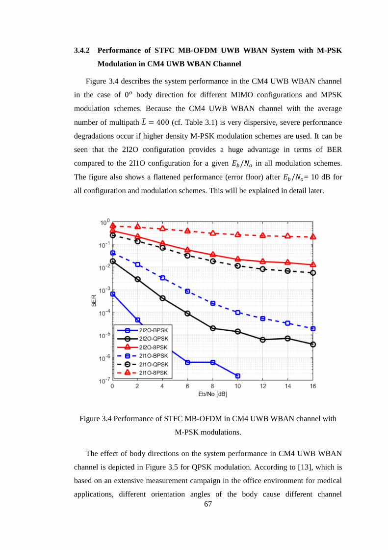
67
3.4.2 Performance of STFC MB-OFDM UWB WBAN System with M-PSK
Modulation in CM4 UWB WBAN Channel
Figure 3.4 describes the system performance in the CM4 UWB WBAN channel
in the case of 0𝑜 body direction for different MIMO configurations and MPSK
modulation schemes. Because the CM4 UWB WBAN channel with the average
number of multipath �̅� = 400 (cf. Table 3.1) is very dispersive, severe performance
degradations occur if higher density M-PSK modulation schemes are used. It can be
seen that the 2I2O configuration provides a huge advantage in terms of BER
compared to the 2I1O configuration for a given 𝐸𝑏/𝑁𝑜 in all modulation schemes.
The figure also shows a flattened performance (error floor) after 𝐸𝑏/𝑁𝑜= 10 dB for
all configuration and modulation schemes. This will be explained in detail later.
Figure 3.4 Performance of STFC MB-OFDM in CM4 UWB WBAN channel with
M-PSK modulations.
The effect of body directions on the system performance in CM4 UWB WBAN
channel is depicted in Figure 3.5 for QPSK modulation. According to [13], which is
based on an extensive measurement campaign in the office environment for medical
applications, different orientation angles of the body cause different channel
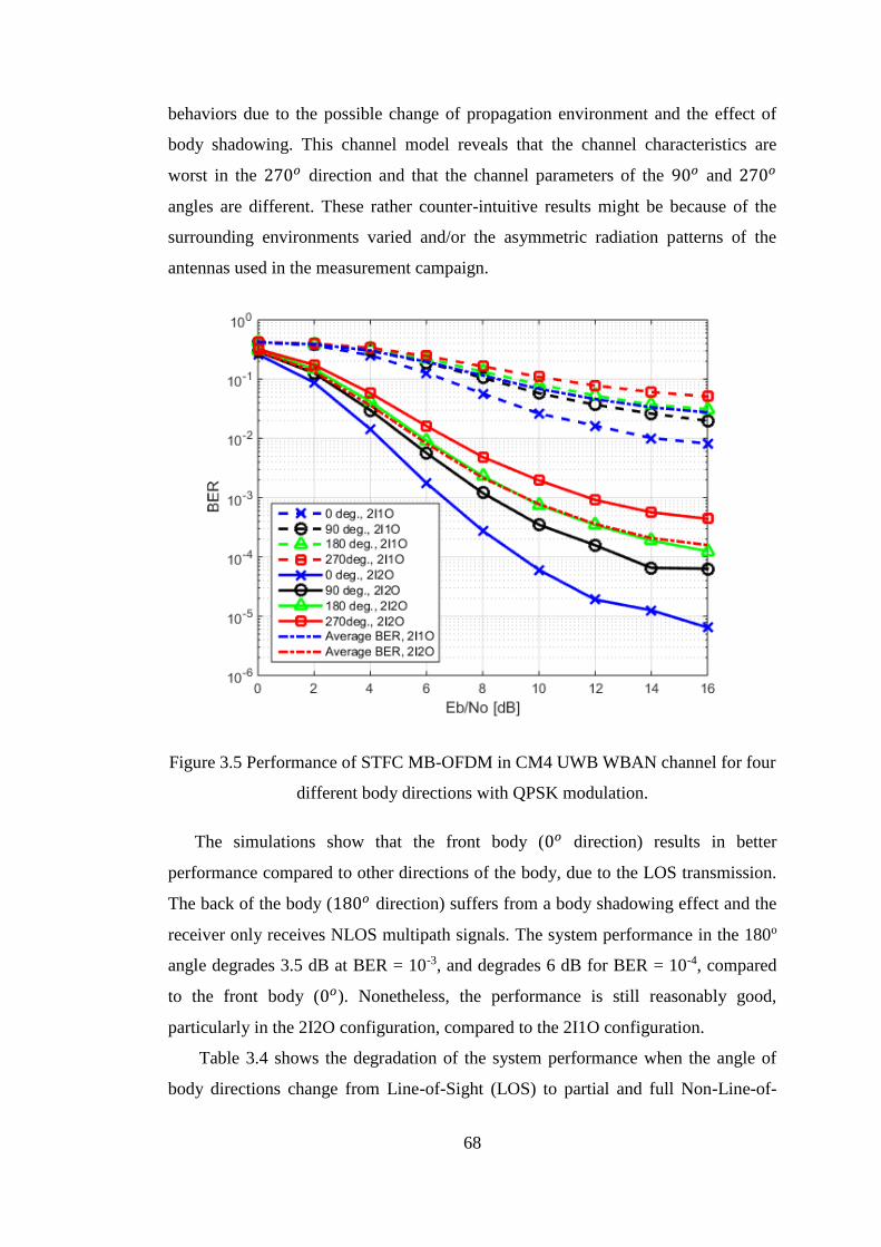
68
behaviors due to the possible change of propagation environment and the effect of
body shadowing. This channel model reveals that the channel characteristics are
worst in the 270𝑜 direction and that the channel parameters of the 90𝑜 and 270𝑜
angles are different. These rather counter-intuitive results might be because of the
surrounding environments varied and/or the asymmetric radiation patterns of the
antennas used in the measurement campaign.
Figure 3.5 Performance of STFC MB-OFDM in CM4 UWB WBAN channel for four
different body directions with QPSK modulation.
The simulations show that the front body (0𝑜 direction) results in better
performance compared to other directions of the body, due to the LOS transmission.
The back of the body (180𝑜 direction) suffers from a body shadowing effect and the
receiver only receives NLOS multipath signals. The system performance in the 180o
angle degrades 3.5 dB at BER = 10-3, and degrades 6 dB for BER = 10-4, compared
to the front body (0𝑜). Nonetheless, the performance is still reasonably good,
particularly in the 2I2O configuration, compared to the 2I1O configuration.
Table 3.4 shows the degradation of the system performance when the angle of
body directions change from Line-of-Sight (LOS) to partial and full Non-Line-of-
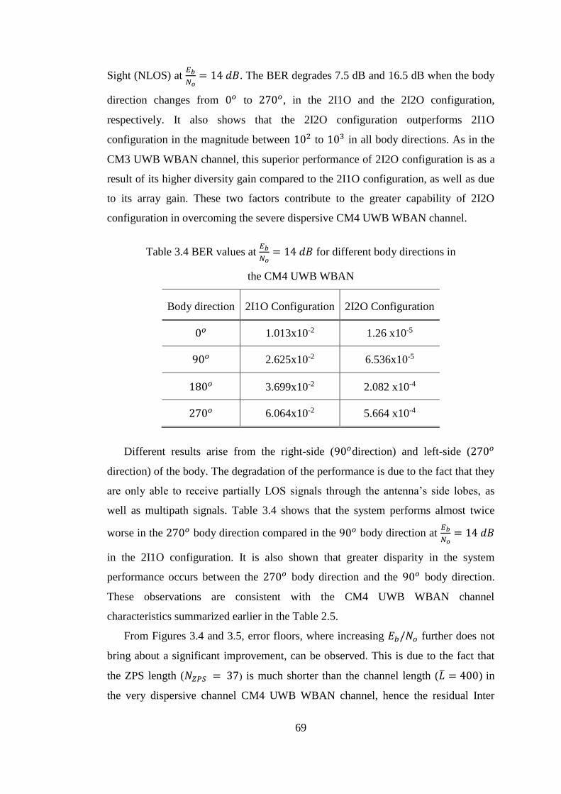
69
Sight (NLOS) at 𝐸𝑏
𝑁𝑜= 14 𝑑𝐵. The BER degrades 7.5 dB and 16.5 dB when the body
direction changes from 0𝑜 to 270𝑜, in the 2I1O and the 2I2O configuration,
respectively. It also shows that the 2I2O configuration outperforms 2I1O
configuration in the magnitude between 102 to 103 in all body directions. As in the
CM3 UWB WBAN channel, this superior performance of 2I2O configuration is as a
result of its higher diversity gain compared to the 2I1O configuration, as well as due
to its array gain. These two factors contribute to the greater capability of 2I2O
configuration in overcoming the severe dispersive CM4 UWB WBAN channel.
Table 3.4 BER values at 𝐸𝑏
𝑁𝑜= 14 𝑑𝐵 for different body directions in
the CM4 UWB WBAN
Body direction 2I1O Configuration 2I2O Configuration
0𝑜 1.013x10⁻² 1.26 x10⁻⁵
90𝑜 2.625x10⁻² 6.536x10⁻⁵
180𝑜 3.699x10⁻² 2.082 x10⁻⁴
270𝑜 6.064x10⁻² 5.664 x10⁻⁴
Different results arise from the right-side (90𝑜direction) and left-side (270𝑜
direction) of the body. The degradation of the performance is due to the fact that they
are only able to receive partially LOS signals through the antenna’s side lobes, as
well as multipath signals. Table 3.4 shows that the system performs almost twice
worse in the 270𝑜 body direction compared in the 90𝑜 body direction at 𝐸𝑏
𝑁𝑜= 14 𝑑𝐵
in the 2I1O configuration. It is also shown that greater disparity in the system
performance occurs between the 270𝑜 body direction and the 90𝑜 body direction.
These observations are consistent with the CM4 UWB WBAN channel
characteristics summarized earlier in the Table 2.5.
From Figures 3.4 and 3.5, error floors, where increasing 𝐸𝑏/𝑁𝑜 further does not
bring about a significant improvement, can be observed. This is due to the fact that
the ZPS length (𝑁𝑍𝑃𝑆 = 37) is much shorter than the channel length (�̅� = 400) in
the very dispersive channel CM4 UWB WBAN channel, hence the residual Inter

70
Symbol Interference (ISI) cannot be neutralized completely by the ZPS. This is the
reason why the MB-OFDM technique has been proposed where consecutive MB-
OFDM symbols are transmitted over different RF frequencies, thus avoiding the
residual ISI. For simplicity, simulations are run here in the baseband, rather than in
the RF band, thus the error floor can be observed. In other words, the performance
provided in this work serves as the lower bound of the improvement that could be
provided by the proposed system.
It is worth to note that although the level of performance improvement achieved
by the proposed STFC MB-OFDM UWB WBAN system compared to the
conventional MB-OFDM UWB WBAN system might be different should a different
channel model be used, the overall idea of the proposed scheme could still be valid
for other channel models.
3.5 Conclusion
In this chapter, we propose the use of MB-OFDM UWB as an alternative
physical layer for WBAN system, in combination with Space-Time-Frequency-Code
Multi-Input Multi-Output (STFC MIMO) techniques, referred to as STFC MB-
OFDM UWB. STFCs are the extended versions of the conventional Space-Time
Block Codes (STBCs) to a three-dimensional processing, namely space, time and
frequency domain processing, to increase further the system diversity. Intuitively,
this proposal may be able to provide better performance, higher data rate, and greater
range at the price of a modest increase in complexity.
In order to prove that the proposed scheme is worthy to be the high speed
WBAN physical layer, we investigate the performance of the STFC MB-OFDM
UWB system over the CM3 and CM4 UWB WBAN channels, by employing the
Alamouti code. 2I1O and 2I2O MIMO configurations and different M-PSK
modulations are used for comparison. The effect of body directions toward a fixed
external transceiver is also evaluated by simulations. Simulation results confirm that
the proposed system can achieve significantly better BER performances in the order
of 4.9 and 10.2 dB in the 2I1O and 2I2O configurations, respectively, compared to
the conventional MB-OFDM UWB system. Within the same MIMO configuration,
the system performance improves by 2 - 4 dB if lower density M-PSK modulations
are utilized. Moreover, though the body direction substantially affects the
performance due to the availability of LOS or partial LOS paths, the proposed
71
system is still more robust, compared to the conventional MB-OFDM one. We
conclude that the proposed system can provide a robust, high data rate transmission
for WBAN applications.
One important observation that can be drawn from the simulation result in Figure
3.5 is the system BER performance differs significantly in different body directions,
i.e. the direction of the receiver placed on the surface of the body with respect to
(w.r.t) the fixed external transceiver. This is due to the effects of LOS, partial LOS,
and body shadowing. This observation motivates us to develop the adaptive
modulation and STFC coding algorithms in order to further improve the system
performance, while maintaining its energy efficiency at an acceptable level. This
adaptive WBAN system will be described in details in the next three chapters of this
thesis.
72
CHAPTER 4 DIRECTION-BASED ADAPTIVE WBAN
SYSTEMS
4.1 Introduction
As demonstrated earlier in Chapter 3, the proposed STFC MB-OFDM UWB
WBAN system provide better performance compared to the conventional (SISO)
MB-OFDM UWB, at a price of modest increase in complexity due to higher number
of transmit antennas.
Further, we evaluate the performance of the proposed system in the CM4 UWB
WBAN channel that considers human body movement. One important observation
from the result in Figure 3.5 of Chapter 3 is that the system performance differs
significantly in different body directions. These disparities in the system performance
are because different body directions experience different channel fading levels due
to the combined effects of LOS, partial LOS, or/and body shadowing. In order to
further improve the system performance, while maintaining its energy efficiency at
an acceptable level, we develop the adaptive WBAN systems in which modulation,
power control, and STFC coding algorithms are adaptively adjusted to the
instantaneous channel condition. Two adaptive schemes are consecutively
considered. The first is a simple direction-based adaptive scheme and the second a
more complex BER-based adaptive scheme. The former adaptive scheme is
described in detail in this chapter, and the latter is discussed in Chapter 5.
As has been analyzed in Section 2.5 of the Literature review, adaptive techniques
are common tools for performance enhancement in many wireless communication
systems. However, an adaptive modulation and STFC coding scheme for the STFC
MB-OFDM UWB WBAN physical layer has not been examined in the literature.
Therefore, this chapter proposes a simple but effective adaptive WBAN system.
The proposed adaptive system is a body direction based adaptive algorithm
implemented in STFC MB-OFDM UWB WBAN, in order to improve the average
performance and/or reduce the power consumption of the body-to-external link for
WBAN applications. The core idea is that a combination of different digital
modulation schemes (BPSK, QPSK), powers of signal constellations, and STFC
coding rates is adaptively selected, depending on the body direction w.r.t. the
transmitter. The adaption is carried out by the measurement of angles of the body
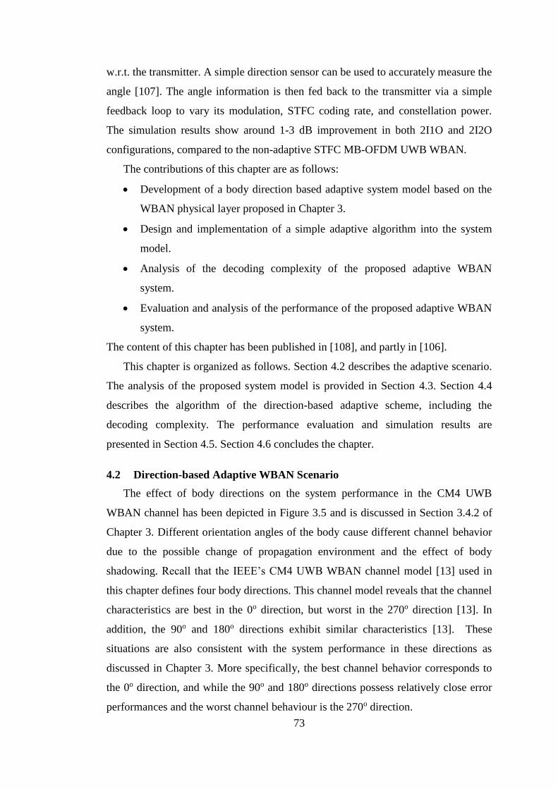
73
w.r.t. the transmitter. A simple direction sensor can be used to accurately measure the
angle [107]. The angle information is then fed back to the transmitter via a simple
feedback loop to vary its modulation, STFC coding rate, and constellation power.
The simulation results show around 1-3 dB improvement in both 2I1O and 2I2O
configurations, compared to the non-adaptive STFC MB-OFDM UWB WBAN.
The contributions of this chapter are as follows:
Development of a body direction based adaptive system model based on the
WBAN physical layer proposed in Chapter 3.
Design and implementation of a simple adaptive algorithm into the system
model.
Analysis of the decoding complexity of the proposed adaptive WBAN
system.
Evaluation and analysis of the performance of the proposed adaptive WBAN
system.
The content of this chapter has been published in [108], and partly in [106].
This chapter is organized as follows. Section 4.2 describes the adaptive scenario.
The analysis of the proposed system model is provided in Section 4.3. Section 4.4
describes the algorithm of the direction-based adaptive scheme, including the
decoding complexity. The performance evaluation and simulation results are
presented in Section 4.5. Section 4.6 concludes the chapter.
4.2 Direction-based Adaptive WBAN Scenario
The effect of body directions on the system performance in the CM4 UWB
WBAN channel has been depicted in Figure 3.5 and is discussed in Section 3.4.2 of
Chapter 3. Different orientation angles of the body cause different channel behavior
due to the possible change of propagation environment and the effect of body
shadowing. Recall that the IEEE’s CM4 UWB WBAN channel model [13] used in
this chapter defines four body directions. This channel model reveals that the channel
characteristics are best in the 0o direction, but worst in the 270o direction [13]. In
addition, the 90o and 180o directions exhibit similar characteristics [13]. These
situations are also consistent with the system performance in these directions as
discussed in Chapter 3. More specifically, the best channel behavior corresponds to
the 0o direction, and while the 90o and 180o directions possess relatively close error
performances and the worst channel behaviour is the 270o direction.
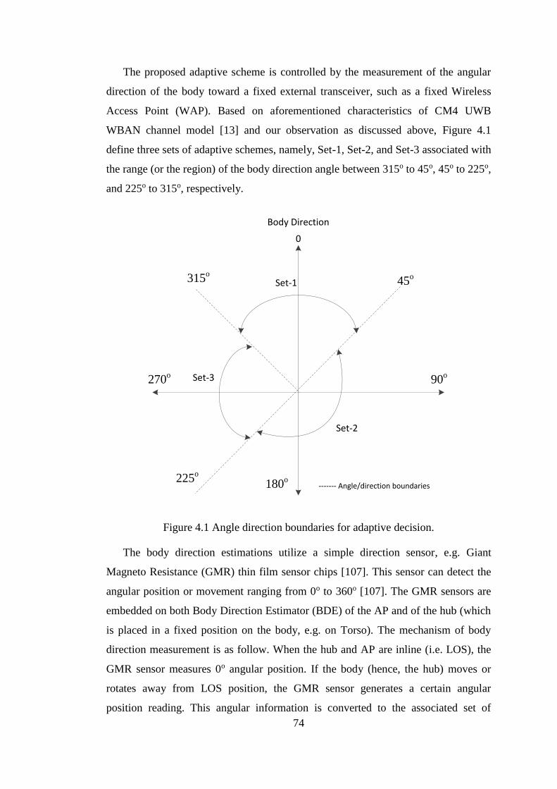
74
The proposed adaptive scheme is controlled by the measurement of the angular
direction of the body toward a fixed external transceiver, such as a fixed Wireless
Access Point (WAP). Based on aforementioned characteristics of CM4 UWB
WBAN channel model [13] and our observation as discussed above, Figure 4.1
define three sets of adaptive schemes, namely, Set-1, Set-2, and Set-3 associated with
the range (or the region) of the body direction angle between 315o to 45o, 45o to 225o,
and 225o to 315o, respectively.
Body Direction
0
45oSet-1
Set-2
Set-3
------- Angle/direction boundaries
90o
180o225o
270o
315o
Figure 4.1 Angle direction boundaries for adaptive decision.
The body direction estimations utilize a simple direction sensor, e.g. Giant
Magneto Resistance (GMR) thin film sensor chips [107]. This sensor can detect the
angular position or movement ranging from 0o to 360o [107]. The GMR sensors are
embedded on both Body Direction Estimator (BDE) of the AP and of the hub (which
is placed in a fixed position on the body, e.g. on Torso). The mechanism of body
direction measurement is as follow. When the hub and AP are inline (i.e. LOS), the
GMR sensor measures 0o angular position. If the body (hence, the hub) moves or
rotates away from LOS position, the GMR sensor generates a certain angular
position reading. This angular information is converted to the associated set of
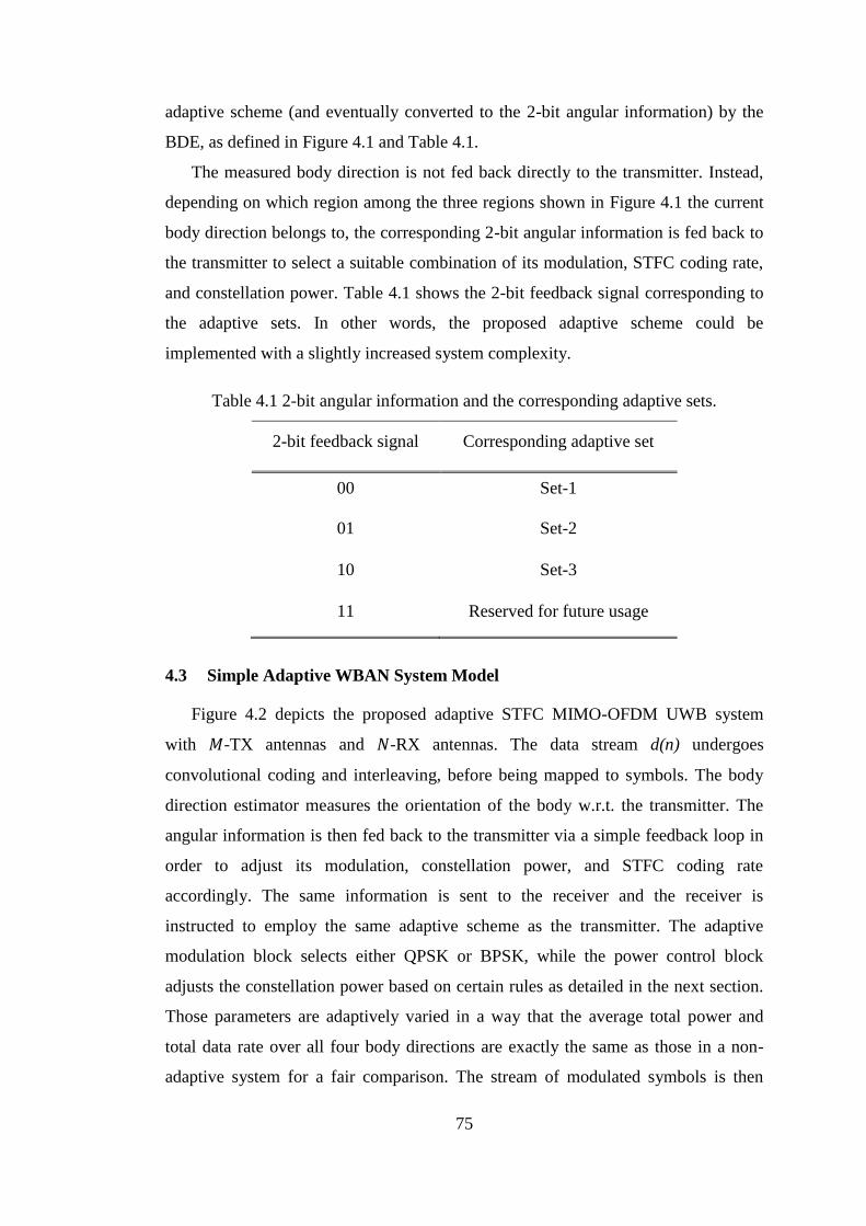
75
adaptive scheme (and eventually converted to the 2-bit angular information) by the
BDE, as defined in Figure 4.1 and Table 4.1.
The measured body direction is not fed back directly to the transmitter. Instead,
depending on which region among the three regions shown in Figure 4.1 the current
body direction belongs to, the corresponding 2-bit angular information is fed back to
the transmitter to select a suitable combination of its modulation, STFC coding rate,
and constellation power. Table 4.1 shows the 2-bit feedback signal corresponding to
the adaptive sets. In other words, the proposed adaptive scheme could be
implemented with a slightly increased system complexity.
Table 4.1 2-bit angular information and the corresponding adaptive sets.
2-bit feedback signal Corresponding adaptive set
00 Set-1
01 Set-2
10 Set-3
11 Reserved for future usage
4.3 Simple Adaptive WBAN System Model
Figure 4.2 depicts the proposed adaptive STFC MIMO-OFDM UWB system
with 𝑀-TX antennas and 𝑁-RX antennas. The data stream d(n) undergoes
convolutional coding and interleaving, before being mapped to symbols. The body
direction estimator measures the orientation of the body w.r.t. the transmitter. The
angular information is then fed back to the transmitter via a simple feedback loop in
order to adjust its modulation, constellation power, and STFC coding rate
accordingly. The same information is sent to the receiver and the receiver is
instructed to employ the same adaptive scheme as the transmitter. The adaptive
modulation block selects either QPSK or BPSK, while the power control block
adjusts the constellation power based on certain rules as detailed in the next section.
Those parameters are adaptively varied in a way that the average total power and
total data rate over all four body directions are exactly the same as those in a non-
adaptive system for a fair comparison. The stream of modulated symbols is then
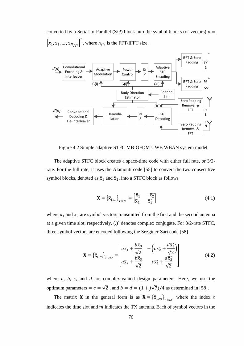
76
converted by a Serial-to-Parallel (S/P) block into the symbol blocks (or vectors) x̅ =
[𝑥1, 𝑥2, … , 𝑥𝑁𝑓𝑓𝑡]𝑇
, where 𝑁𝑓𝑓𝑡 is the FFT/IFFT size.
TX 1 . .
M
RX 1
N
d(n) Convolutional Encoding & Interleaver
Adaptive Modulation
S/P
AdaptiveSTC
Encoding
IFFT & Zero Padding
IFFT & Zero Padding
Zero Padding Removal &
FFT
Zero Padding Removal &
FFT
SM
STC Decoding
P/S
Demodu-lation
Convolutional Decoding &
De-Interleaver
đ(n)
Power Control
Body Direction Estimator
Channel h(i)
G(i) G(i) G(i)
Figure 4.2 Simple adaptive STFC MB-OFDM UWB WBAN system model.
The adaptive STFC block creates a space-time code with either full rate, or 3/2-
rate. For the full rate, it uses the Alamouti code [55] to convert the two consecutive
symbol blocks, denoted as x̅1 and x̅2, into a STFC block as follows
𝐗 = {x̅𝑡,𝑚}𝑇×𝑀
= [x̅1 −x̅2
∗
x̅2 x̅1∗ ] (4.1)
where x̅1 and x̅2 are symbol vectors transmitted from the first and the second antenna
at a given time slot, respectively. (.)* denotes complex conjugate. For 3/2-rate STFC,
three symbol vectors are encoded following the Sezginer-Sari code [58]
𝐗 = {x̅𝑡,𝑚}𝑇×𝑀
=
[ 𝑎x̅1 +
𝑏x̅3
√2−(𝑐x̅2
∗ +𝑑x̅3
∗
√2)
𝑎x̅2 +𝑏x̅3
√2𝑐x̅1
∗ +𝑑x̅3
∗
√2 ]
(4.2)
where a, b, c, and d are complex-valued design parameters. Here, we use the
optimum parameters = 𝑐 = √2 , and 𝑏 = 𝑑 = (1 + 𝑗√7)/4 as determined in [58].
The matrix 𝐗 in the general form is as 𝐗 = {x̅𝑡,𝑚}𝑇×𝑀
, where the index 𝑡
indicates the time slot and 𝑚 indicates the TX antenna. Each of symbol vectors in the
77
matrix 𝐗 is then converted into an 𝑁𝑓𝑓𝑡-point MB-OFDM symbol by the IFFT block,
resulting in the STFC code matrix 𝐗𝑂𝐹𝐷𝑀 whose elements are the 𝑁𝑓𝑓𝑡-point IFFT of
the corresponding symbol vectors x̅𝑡,𝑚 in 𝐗. Further, the input-output relation of the
transmitted and received MB-OFDM symbols for both STFC codes follows the
signal analysis in Eq. (3.2) to Eq. (3.8) of Chapter 3. Whereas the maximum
likelihood decoding of the received symbol in the system employing Alamouti code
follows the analysis in Eq. (3.9) to Eq. (3.13) of Chapter 3.
The ML detection of MB-OFDM symbols employing the Sezginer-Sari code is
slightly different, since this code consists of three symbols x̅1, x̅2 and x̅3. In order to
reduce the complexity of the receiver, the Sezginer-Sari code detection employs two
stage detectors [58]. The first stage computes the intermediate signals resulting in the
estimate of vector symbol x̅3, followed by the pre-detection of vector symbol x̅1 and
x̅2 given the estimated values of x̅3 are known, and in the second stage ML estimator
is used to finally decode x̅1, x̅2 and x̅3 [58]. Here, we briefly summarize the ML
detection procedures from [58] as adopted in our proposed system, except that
elements of both transmit and receive signal matrix is a vector of MB-OFDM
symbols. Let us consider 2I2O, in which ℛ is the received signal matrix from the
transmit signal matrix 𝐗. Denote 𝐙 as the matrix of the intermediate signal whose
elements are computed as follow
z̅1 = �̅�1 − 𝑏(�̅�11 + �̅�12) • x̅3
√2 (4.3)
z̅2 = �̅�2 − 𝑑(�̅�11 + �̅�12) • x̅3
∗
√2 (4.4)
z̅3 = �̅�3 − 𝑏(�̅�21 + �̅�22) • x̅3
√2 (4.5)
z̅4 = �̅�4 − 𝑑(�̅�21 + �̅�22) • x̅3
∗
√2 (4.6)
for a given value of x̅3. By mathematical manipulation as analyzed in Eq. (15.a) to
Eq. (16.d) of [58], we use this intermediate signal to calculate the estimate of x̃̅1 and
x̃̅2 conditional on x̃̅3 as follow
78
x̃̅1 =(�̅�11
∗ • z̅1 + �̅�21∗ • z̅3)
𝑎+
(�̅�12 • z̅2∗ + �̅�22 • z̅4
∗)
𝑐∗
= (|�̅�11|2 + |�̅�12|
2 + |�̅�21|2 + |�̅�22|
2) • x̅1 (4.7)
and
x̃̅2 =(�̅�12
∗ • z̅1 + �̅�22∗ • z̅3)
𝑎−
(�̅�11 • z̅2∗ + �̅�21 • z̅4
∗)
𝑐∗
= (|�̅�11|2 + |�̅�12|
2 + |�̅�21|2 + |�̅�22|
2) • x̅2 (4.8)
As has been explained previously in Section 3.3.2 of Chapter 3, each data point in an
MB-OFDM symbol can be decoded separately rather than jointly [30]. By applying
each element of vector x̃̅1 and x̃̅2 to a threshold detector [58], each data symbol at the
𝑘-th subcarrier, for 𝑘 = 1,… ,𝑁𝐷 can be decoded as follow
�̃�1,𝑘 = (|�̅�11|2 + |�̅�12|
2 + |�̅�21|2 + |�̅�22|
2)𝑥1,𝑘 (4.9)
and
�̃�2,𝑘 = (|�̅�11|2 + |�̅�12|
2 + |�̅�21|2 + |�̅�22|
2)𝑥2,𝑘 (4.10)
At this point, we have estimated �̃�1,𝑘 and �̃�2,𝑘, given symbol 𝑥3,𝑘 is known. Now, to
estimate symbol 𝑥3,𝑘 by the ML detector, we only need to compute the Euclidean
distance for (�̃�1,𝑘, �̃�2,𝑘, 𝑥3,𝑘) to get �̃�3,𝑘, instead of computing the ML metrics for all
(𝑥1,𝑘, 𝑥2,𝑘, 𝑥3,𝑘). In other words, the optimum receiver computes 𝒫 operations to
estimate 𝑥3,𝑘, where 𝒫 is the constellation size. Thus, it only requires a linear ML
detector [58]. Readers may refer to [58] for detailed analysis of the Sezginer-Sari
code detection.
4.4 Direction-based Adaptive WBAN Scheme
4.4.1 Adaptive Algorithm
Our proposed adaptive algorithm employs either QPSK or BPSK for modulation.
In order to be able to achieve higher capacity particularly when the channel exhibit
good SNR, we use two different STFC coding rates, namely coding rate-1 which
employs the Alamouti code, and coding rate-3/2 which utilizes the Sezginer-Sari 3/2
rate code to provide 1.5 higher capacity as compared to capacity supported by the

79
Alamouti code. The Sezginer-Sari code requires a linear ML detection and the
complexity is comparable to the Alamouti code [55], [58]. However, the penalty in
term of BER performance with QPSK modulation is 3.8 dB lower than Alamouti
scheme [58]. Therefore, we use this code only in the front body where the signal
reception is expected to be good. The normalized transmitted constellation power
may take one of the three values 0.5, 1, and 1.5. The selection of the adaptive scheme
is carried out in a way that the average data rate and total transmitted power over all
main four directions of the body are maintained exactly equal to those in the non-
adaptive system for a fair comparison. It is noted that the non-adaptive STFC
MIMO-OFDM UWB WBAN system employs the Alamouti full rate code, unit
power constellation, and a QPSK modulation. In other words, the following
constraints need to be maintained.
1. Data rate constraint: the lowest density signal constellation (BPSK) is used
for the worst link (270o) in order to improve the system error performance
over this direction. A higher density constellation (QPSK) is used for all other
three directions. The highest rate STFC (rate-3/2) is selected for the best link
(0o) while the rate-1 STFC is selected for all three remaining directions. Thus
the average spectrum efficiency over four main directions is maintained at 2
bits/s/Hz which is exactly the same as that in the non-adaptive system.
2. Power constraint: the unit normalized power is selected for the signal
constellations (QPSK) for the 90o and 180o directions, similarly to that in the
non-adaptive system, while the highest power level (1.5) is selected for the
best link (0o) to compensate for the possible performance degradation caused
by the highest STFC coding rate (3/2) chosen for this direction. The above
power allocation leaves the power of 0.5 for the BPSK signal constellation in
the 270o direction. Thus the total transmitted power over all four main
directions is four which is exactly the same as that in the non-adaptive
system. Equivalently, the unit average transmission power per direction is
maintained in both systems.
The core idea behind the proposed algorithm is that the best channel conveys the
most information with the most power allocated while the worse link carries the least
information. Hence, we define three sets of modulation, transmission power and
STFC coding (see Figure 4.1). Set-1 aims to take advantage of the best channel link
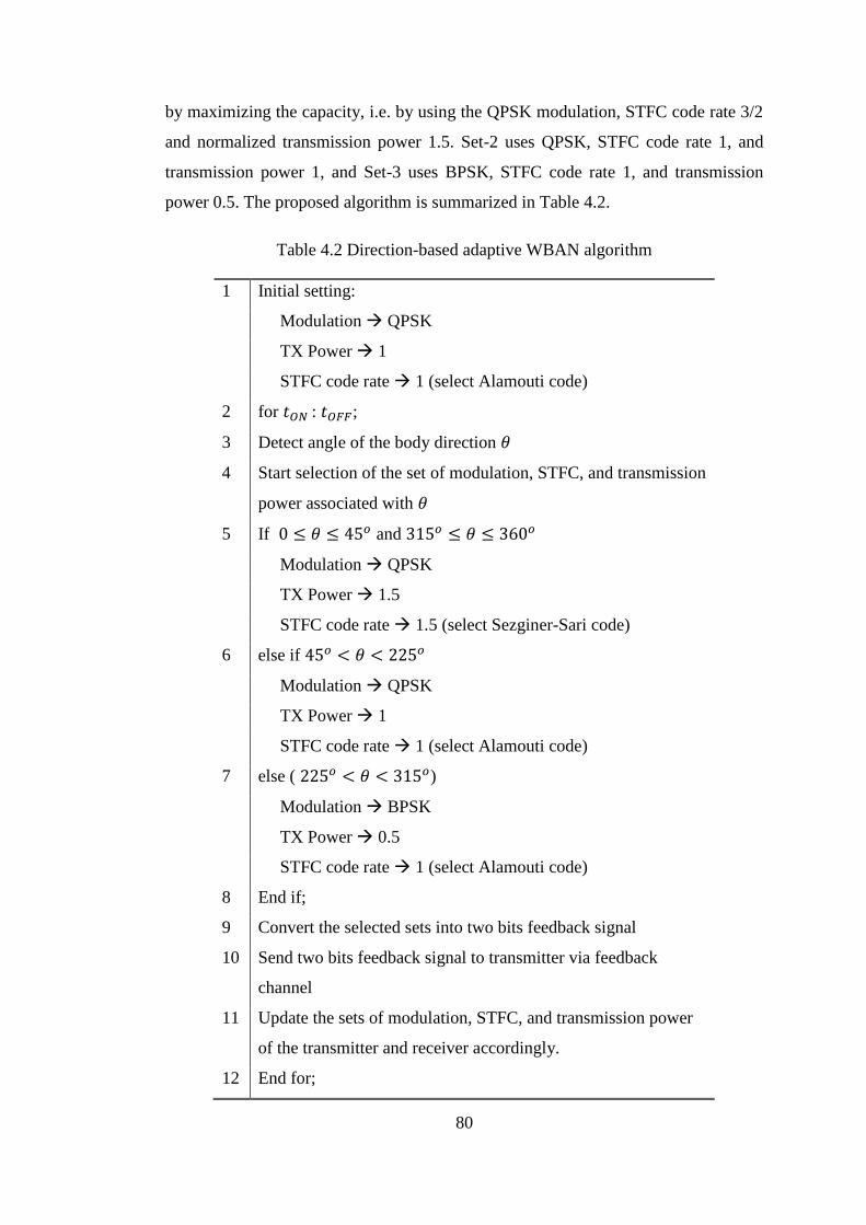
80
by maximizing the capacity, i.e. by using the QPSK modulation, STFC code rate 3/2
and normalized transmission power 1.5. Set-2 uses QPSK, STFC code rate 1, and
transmission power 1, and Set-3 uses BPSK, STFC code rate 1, and transmission
power 0.5. The proposed algorithm is summarized in Table 4.2.
Table 4.2 Direction-based adaptive WBAN algorithm
1 Initial setting:
Modulation QPSK
TX Power 1
STFC code rate 1 (select Alamouti code)
2 for 𝑡𝑂𝑁 : 𝑡𝑂𝐹𝐹;
3 Detect angle of the body direction 𝜃
4 Start selection of the set of modulation, STFC, and transmission
power associated with 𝜃
5 If 0 ≤ 𝜃 ≤ 45𝑜 and 315𝑜 ≤ 𝜃 ≤ 360𝑜
Modulation QPSK
TX Power 1.5
STFC code rate 1.5 (select Sezginer-Sari code)
6 else if 45𝑜 < 𝜃 < 225𝑜
Modulation QPSK
TX Power 1
STFC code rate 1 (select Alamouti code)
7 else ( 225𝑜 < 𝜃 < 315𝑜)
Modulation BPSK
TX Power 0.5
STFC code rate 1 (select Alamouti code)
8 End if;
9 Convert the selected sets into two bits feedback signal
10 Send two bits feedback signal to transmitter via feedback
channel
11 Update the sets of modulation, STFC, and transmission power
of the transmitter and receiver accordingly.
12 End for;
81
4.4.2 Decoding Complexity
Let 𝒫 be the constellation size of the MPSK modulator used in Sets 1 and 2 (here
we use QPSK, so 𝒫 is equal to 4). As a result, the constellation size of the BPSK
modulator used in Set-3 is 𝒫/2.
The decoding process of Set-1with QPSK and 3/2 rate STFC is as follows: first
the decoder has to determine x̃3 from four possible symbols in QPSK, prior to
decoding x̃1and x̃2 symbols. Then, x̃1and x̃2 are decoded independently, given that
x̃3 is known, for every QPSK constellation. Hence, the ML decoding complexity is
the decoding complexity of x̃3, which is in the order of 𝒫, added with the complexity
of two independent decoding processes of x̃1and x̃2 given that x̃3 is known, which is
equal to 2𝒫. Thus the overall decoding complexity of Set-1 is in the order of 3𝒫,
which is consistent with the analysis in [58].
Set-2 uses a QPSK modulator with the full rate Alamouti code as the STFC. The
symbols x̃1 and x̃2 are decoded independently for every constellation, leading to a
2𝒫-decoding complexity.
Set-3 uses the full rate Alamouti code in which x̃1 and x̃2 symbols are decoded
independently for every BPSK constellation point. Therefore the ML decoding
complexity in Set-3 is 2 ×𝒫
2= 𝒫.
There are four possible body directions with three possible adaptive modulation
and coding. If the four body directions are assumed to be equi-probable, i.e., the
probability of each possible direction is 0.25, with the note that Set-2 is used for two
body directions (90o and 180o), the overall complexity of the ML decoding process in
the proposed adaptive scheme is (0.25(3𝒫) + 0.5(2𝒫) + 0.25(𝒫) or 2𝒫, beside
the body direction estimation. It can be inferred that the ML decoding complexity in
our adaptive approach is in the order of 𝒫 or 𝑂(𝒫). It is obvious that the complexity
of this adaptive system only linearly increases with respect to the number of signal
constellations, thanks to relatively simple decoding processes.
4.5 Performance of Direction-Based Adaptive WBAN Systems
In this section, Monte-Carlo simulations, which run on 50,000 OFDM symbols,
are carried out to compare the average BER performance of the adaptive system with
that of the non-adaptive one, assuming perfect channel state estimations are available
at the receiver. The non-adaptive system, as the benchmark, uses QPSK modulation,
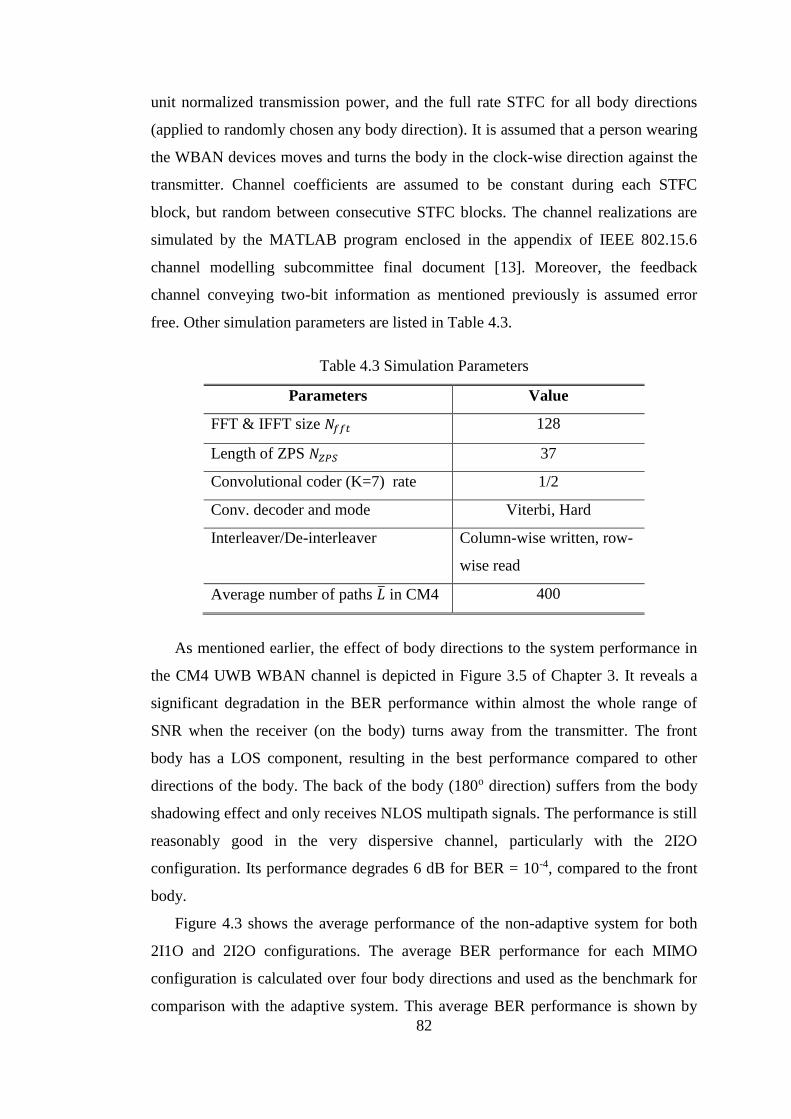
82
unit normalized transmission power, and the full rate STFC for all body directions
(applied to randomly chosen any body direction). It is assumed that a person wearing
the WBAN devices moves and turns the body in the clock-wise direction against the
transmitter. Channel coefficients are assumed to be constant during each STFC
block, but random between consecutive STFC blocks. The channel realizations are
simulated by the MATLAB program enclosed in the appendix of IEEE 802.15.6
channel modelling subcommittee final document [13]. Moreover, the feedback
channel conveying two-bit information as mentioned previously is assumed error
free. Other simulation parameters are listed in Table 4.3.
Table 4.3 Simulation Parameters
Parameters Value
FFT & IFFT size 𝑁𝑓𝑓𝑡 128
Length of ZPS 𝑁𝑍𝑃𝑆 37
Convolutional coder (K=7) rate 1/2
Conv. decoder and mode Viterbi, Hard
Interleaver/De-interleaver Column-wise written, row-
wise read
Average number of paths �̅� in CM4 400
As mentioned earlier, the effect of body directions to the system performance in
the CM4 UWB WBAN channel is depicted in Figure 3.5 of Chapter 3. It reveals a
significant degradation in the BER performance within almost the whole range of
SNR when the receiver (on the body) turns away from the transmitter. The front
body has a LOS component, resulting in the best performance compared to other
directions of the body. The back of the body (180o direction) suffers from the body
shadowing effect and only receives NLOS multipath signals. The performance is still
reasonably good in the very dispersive channel, particularly with the 2I2O
configuration. Its performance degrades 6 dB for BER = 10-4, compared to the front
body.
Figure 4.3 shows the average performance of the non-adaptive system for both
2I1O and 2I2O configurations. The average BER performance for each MIMO
configuration is calculated over four body directions and used as the benchmark for
comparison with the adaptive system. This average BER performance is shown by
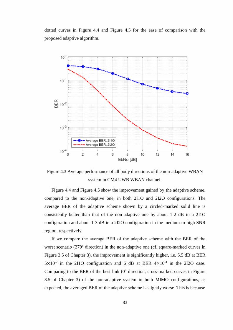
83
dotted curves in Figure 4.4 and Figure 4.5 for the ease of comparison with the
proposed adaptive algorithm.
Figure 4.3 Average performance of all body directions of the non-adaptive WBAN
system in CM4 UWB WBAN channel.
Figure 4.4 and Figure 4.5 show the improvement gained by the adaptive scheme,
compared to the non-adaptive one, in both 2I1O and 2I2O configurations. The
average BER of the adaptive scheme shown by a circled-marked solid line is
consistently better than that of the non-adaptive one by about 1-2 dB in a 2I1O
configuration and about 1-3 dB in a 2I2O configuration in the medium-to-high SNR
region, respectively.
If we compare the average BER of the adaptive scheme with the BER of the
worst scenario (270o direction) in the non-adaptive one (cf. square-marked curves in
Figure 3.5 of Chapter 3), the improvement is significantly higher, i.e. 5.5 dB at BER
5×10⁻² in the 2I1O configuration and 6 dB at BER 4×10⁻⁴ in the 2I2O case.
Comparing to the BER of the best link (0o direction, cross-marked curves in Figure
3.5 of Chapter 3) of the non-adaptive system in both MIMO configurations, as
expected, the averaged BER of the adaptive scheme is slightly worse. This is because
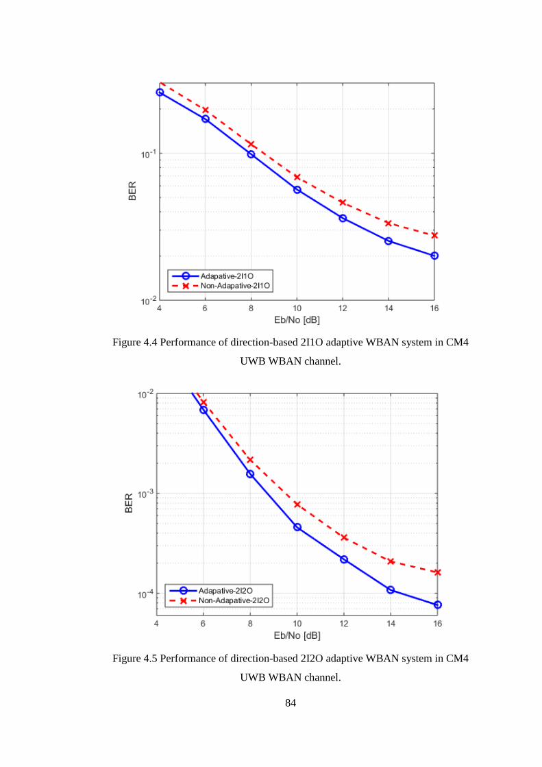
84
Figure 4.4 Performance of direction-based 2I1O adaptive WBAN system in CM4
UWB WBAN channel.
Figure 4.5 Performance of direction-based 2I2O adaptive WBAN system in CM4
UWB WBAN channel.
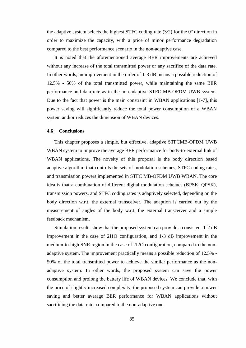
85
the adaptive system selects the highest STFC coding rate (3/2) for the 0o direction in
order to maximize the capacity, with a price of minor performance degradation
compared to the best performance scenario in the non-adaptive case.
It is noted that the aforementioned average BER improvements are achieved
without any increase of the total transmitted power or any sacrifice of the data rate.
In other words, an improvement in the order of 1-3 dB means a possible reduction of
12.5% - 50% of the total transmitted power, while maintaining the same BER
performance and data rate as in the non-adaptive STFC MB-OFDM UWB system.
Due to the fact that power is the main constraint in WBAN applications [1-7], this
power saving will significantly reduce the total power consumption of a WBAN
system and/or reduces the dimension of WBAN devices.
4.6 Conclusions
This chapter proposes a simple, but effective, adaptive STFCMB-OFDM UWB
WBAN system to improve the average BER performance for body-to-external link of
WBAN applications. The novelty of this proposal is the body direction based
adaptive algorithm that controls the sets of modulation schemes, STFC coding rates,
and transmission powers implemented in STFC MB-OFDM UWB WBAN. The core
idea is that a combination of different digital modulation schemes (BPSK, QPSK),
transmission powers, and STFC coding rates is adaptively selected, depending on the
body direction w.r.t. the external transceiver. The adaption is carried out by the
measurement of angles of the body w.r.t. the external transceiver and a simple
feedback mechanism.
Simulation results show that the proposed system can provide a consistent 1-2 dB
improvement in the case of 2I1O configuration, and 1-3 dB improvement in the
medium-to-high SNR region in the case of 2I2O configuration, compared to the non-
adaptive system. The improvement practically means a possible reduction of 12.5% -
50% of the total transmitted power to achieve the similar performance as the non-
adaptive system. In other words, the proposed system can save the power
consumption and prolong the battery life of WBAN devices. We conclude that, with
the price of slightly increased complexity, the proposed system can provide a power
saving and better average BER performance for WBAN applications without
sacrificing the data rate, compared to the non-adaptive one.

86
The simple adaptive WBAN mentioned above exhibits a modest performance
improvement compared to the non-adaptive one. In addition, from the user’s
perspective, this adaptive system offers limited adaptation to only three body
directions. Due to the stringent requirements of a WBAN implementation,
particularly in the robustness and energy efficiency issues as outlined in Section 3.2
of Chapter 3, and also in order to provide full adaptation for any angle of body
direction, it is necessary to refine the adaptive schemes in order to further improve
the system performance. Therefore, our consecutive works propose a new
transmission model and an adaptive algorithm based on the measured BER as metric
for adaptation. These works will be elaborated further in the following chapter.
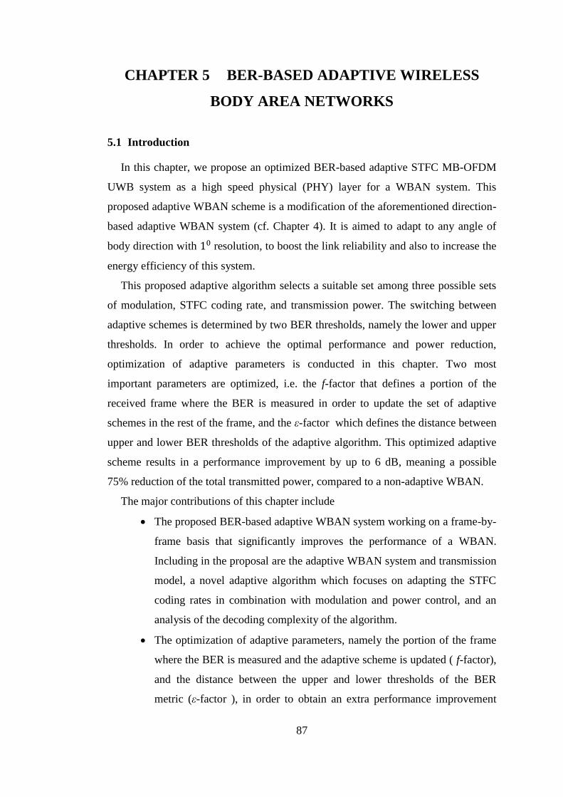
87
CHAPTER 5 BER-BASED ADAPTIVE WIRELESS
BODY AREA NETWORKS
5.1 Introduction
In this chapter, we propose an optimized BER-based adaptive STFC MB-OFDM
UWB system as a high speed physical (PHY) layer for a WBAN system. This
proposed adaptive WBAN scheme is a modification of the aforementioned direction-
based adaptive WBAN system (cf. Chapter 4). It is aimed to adapt to any angle of
body direction with 10 resolution, to boost the link reliability and also to increase the
energy efficiency of this system.
This proposed adaptive algorithm selects a suitable set among three possible sets
of modulation, STFC coding rate, and transmission power. The switching between
adaptive schemes is determined by two BER thresholds, namely the lower and upper
thresholds. In order to achieve the optimal performance and power reduction,
optimization of adaptive parameters is conducted in this chapter. Two most
important parameters are optimized, i.e. the f-factor that defines a portion of the
received frame where the BER is measured in order to update the set of adaptive
schemes in the rest of the frame, and the ε-factor which defines the distance between
upper and lower BER thresholds of the adaptive algorithm. This optimized adaptive
scheme results in a performance improvement by up to 6 dB, meaning a possible
75% reduction of the total transmitted power, compared to a non-adaptive WBAN.
The major contributions of this chapter include
The proposed BER-based adaptive WBAN system working on a frame-by-
frame basis that significantly improves the performance of a WBAN.
Including in the proposal are the adaptive WBAN system and transmission
model, a novel adaptive algorithm which focuses on adapting the STFC
coding rates in combination with modulation and power control, and an
analysis of the decoding complexity of the algorithm.
The optimization of adaptive parameters, namely the portion of the frame
where the BER is measured and the adaptive scheme is updated ( f-factor),
and the distance between the upper and lower thresholds of the BER
metric (ε-factor ), in order to obtain an extra performance improvement
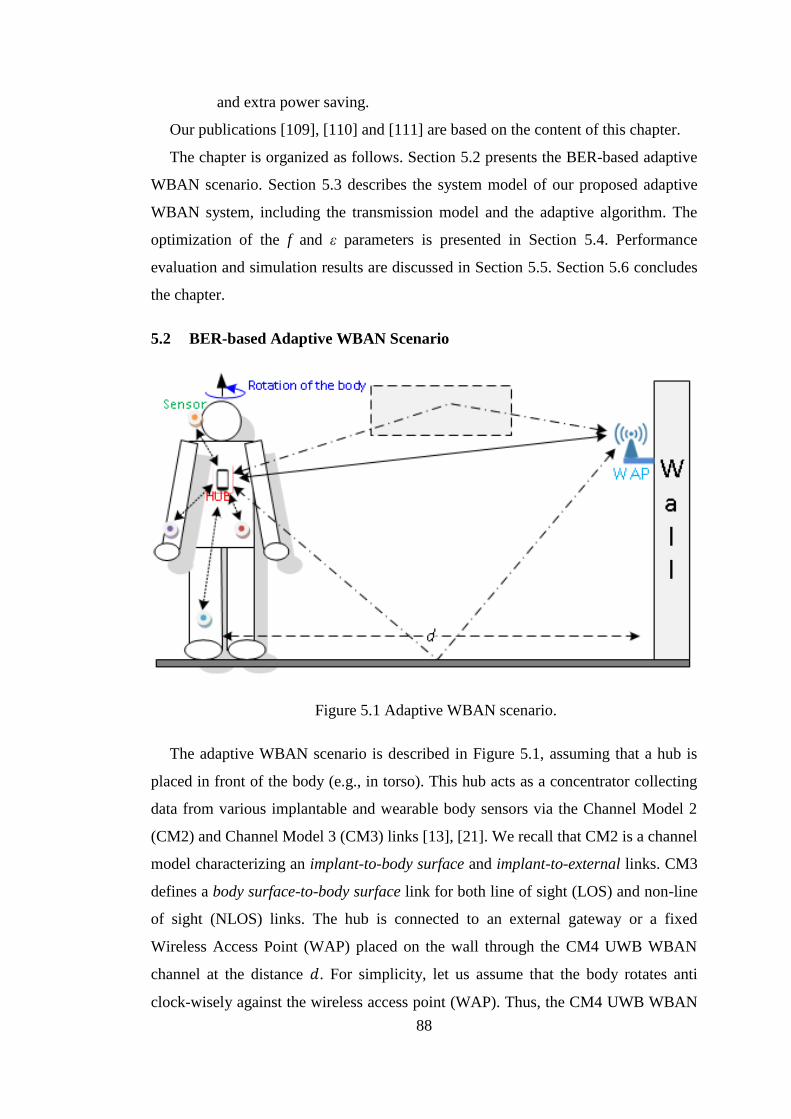
88
and extra power saving.
Our publications [109], [110] and [111] are based on the content of this chapter.
The chapter is organized as follows. Section 5.2 presents the BER-based adaptive
WBAN scenario. Section 5.3 describes the system model of our proposed adaptive
WBAN system, including the transmission model and the adaptive algorithm. The
optimization of the f and ε parameters is presented in Section 5.4. Performance
evaluation and simulation results are discussed in Section 5.5. Section 5.6 concludes
the chapter.
5.2 BER-based Adaptive WBAN Scenario
Figure 5.1 Adaptive WBAN scenario.
The adaptive WBAN scenario is described in Figure 5.1, assuming that a hub is
placed in front of the body (e.g., in torso). This hub acts as a concentrator collecting
data from various implantable and wearable body sensors via the Channel Model 2
(CM2) and Channel Model 3 (CM3) links [13], [21]. We recall that CM2 is a channel
model characterizing an implant-to-body surface and implant-to-external links. CM3
defines a body surface-to-body surface link for both line of sight (LOS) and non-line
of sight (NLOS) links. The hub is connected to an external gateway or a fixed
Wireless Access Point (WAP) placed on the wall through the CM4 UWB WBAN
channel at the distance 𝑑. For simplicity, let us assume that the body rotates anti
clock-wisely against the wireless access point (WAP). Thus, the CM4 UWB WBAN
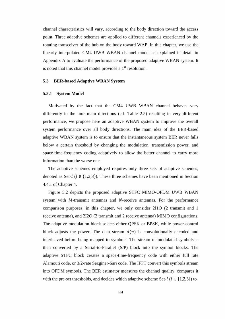
89
channel characteristics will vary, according to the body direction toward the access
point. Three adaptive schemes are applied to different channels experienced by the
rotating transceiver of the hub on the body toward WAP. In this chapter, we use the
linearly interpolated CM4 UWB WBAN channel model as explained in detail in
Appendix A to evaluate the performance of the proposed adaptive WBAN system. It
is noted that this channel model provides a 10 resolution.
5.3 BER-based Adaptive WBAN System
5.3.1 System Model
Motivated by the fact that the CM4 UWB WBAN channel behaves very
differently in the four main directions (c.f. Table 2.5) resulting in very different
performance, we propose here an adaptive WBAN system to improve the overall
system performance over all body directions. The main idea of the BER-based
adaptive WBAN system is to ensure that the instantaneous system BER never falls
below a certain threshold by changing the modulation, transmission power, and
space-time-frequency coding adaptively to allow the better channel to carry more
information than the worse one.
The adaptive schemes employed requires only three sets of adaptive schemes,
denoted as Set-𝑙 (𝑙 ∈ {1,2,3}). These three schemes have been mentioned in Section
4.4.1 of Chapter 4.
Figure 5.2 depicts the proposed adaptive STFC MIMO-OFDM UWB WBAN
system with 𝑀-transmit antennas and 𝑁-receive antennas. For the performance
comparison purposes, in this chapter, we only consider 2I1O (2 transmit and 1
receive antenna), and 2I2O (2 transmit and 2 receive antenna) MIMO configurations.
The adaptive modulation block selects either QPSK or BPSK, while power control
block adjusts the power. The data stream 𝑑(𝑛) is convolutionally encoded and
interleaved before being mapped to symbols. The stream of modulated symbols is
then converted by a Serial-to-Parallel (S/P) block into the symbol blocks. The
adaptive STFC block creates a space-time-frequency code with either full rate
Alamouti code, or 3/2-rate Sezginer-Sari code. The IFFT convert this symbols stream
into OFDM symbols. The BER estimator measures the channel quality, compares it
with the pre-set thresholds, and decides which adaptive scheme Set-𝑙 (𝑙 ∈ {1,2,3}) to

90
TX 1 . .
M
RX 1
N
d(n)
S1
Convolutional Encoding & Interleaver
Adaptive Modulation
S/P
AdaptiveSTFC
Encoding
IFFT & Zero Padding
IFFT & Zero Padding
Zero Padding Removal &
FFT
Zero Padding Removal &
FFT rN
r1
SM
AdaptiveSTFC
Decoding
P/S
Adaptive Demodulation
Convolutional Decoding & De-Interlver
đ(n)
Power Control
BER EstimatorChannel
h(i)
G(i) G(i) G(i)
Figure 5.2 BER–based adaptive STFC MB-OFDM UWB WBAN system.
be employed. The decided adaptive scheme Set-𝑙 is then converted to 2-bit
information as expressed in Table 4.1 of Chapter 4, and feeds this information back
to the transmitter via a feedback channel, in order to adjust its modulation,
constellation power, and STFC coding rate for the remaining portion of frame
transmission. As assumed earlier, the feedback channel in this case is error free. It is
worth to note that the WBAN systems require minimum transceiver complexity to
conserve the energy, as mentioned in Chapter 2. Therefore, we searched for the least
complex approach to be employed in our adaptive system. Here, we did not consider
a channel estimator because it requires a complex receiver, leading to the increase of
the energy consumption and the implementation cost.
Selection of the adaptive scheme Set-𝑙 is done in a way that the average
throughput and total transmitted power, assuming an equal occurrence probability of
each Set-𝑙, are maintained exactly equal to those in a non-adaptive system for a fair
comparison. Here, the non-adaptive system employs the QPSK, rate-1 STFC, and a
unit normalized power, providing a spectral efficiency of 2 bps/Hz. The reverse
processes takes place in the receiver. Note that the full description of this signal
processing has been provided in Chapters 3 and 4. The signal analysis of this system
follows Eqs. (3.2 - 3.13) of Chapter 3 and Eqs. (4.2 - 4.10) of Chapter 4.
We recall the three adaptive schemes which have been defined in Section 4.4.1 of
Chapter 4, except that the switching between the adaptive schemes in this scenario is
triggered by the measured BER on the corresponding link. These three adaptive
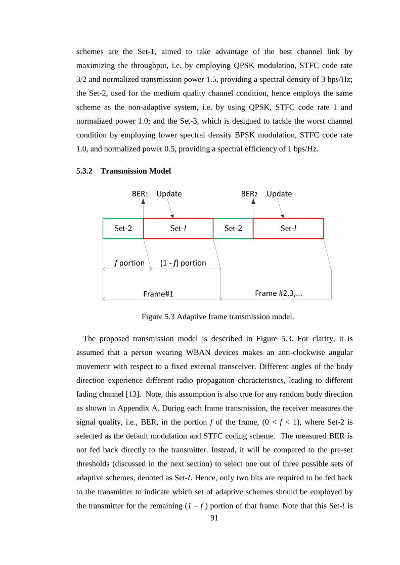
91
schemes are the Set-1, aimed to take advantage of the best channel link by
maximizing the throughput, i.e. by employing QPSK modulation, STFC code rate
3/2 and normalized transmission power 1.5, providing a spectral density of 3 bps/Hz;
the Set-2, used for the medium quality channel condition, hence employs the same
scheme as the non-adaptive system, i.e. by using QPSK, STFC code rate 1 and
normalized power 1.0; and the Set-3, which is designed to tackle the worst channel
condition by employing lower spectral density BPSK modulation, STFC code rate
1.0, and normalized power 0.5, providing a spectral efficiency of 1 bps/Hz.
5.3.2 Transmission Model
Set-2 Set-l Set-2 Set-l
BER1 Update BER2 Update
f portion (1 - f) portion
Frame#1 Frame #2,3,...
Figure 5.3 Adaptive frame transmission model.
The proposed transmission model is described in Figure 5.3. For clarity, it is
assumed that a person wearing WBAN devices makes an anti-clockwise angular
movement with respect to a fixed external transceiver. Different angles of the body
direction experience different radio propagation characteristics, leading to different
fading channel [13]. Note, this assumption is also true for any random body direction
as shown in Appendix A. During each frame transmission, the receiver measures the
signal quality, i.e., BER, in the portion f of the frame, (0 < f < 1), where Set-2 is
selected as the default modulation and STFC coding scheme. The measured BER is
not fed back directly to the transmitter. Instead, it will be compared to the pre-set
thresholds (discussed in the next section) to select one out of three possible sets of
adaptive schemes, denoted as Set-𝑙. Hence, only two bits are required to be fed back
to the transmitter to indicate which set of adaptive schemes should be employed by
the transmitter for the remaining (1 – f ) portion of that frame. Note that this Set-𝑙 is

92
known to the receiver. After completion of a frame transmission, the first portion f of
the next frame will utilize Set-2 again, followed by the same procedure as above.
Measuring and updating the adaptive set at the first f % of the frame does not
imply that the first f % of the frame must be the overhead, hence sacrificing f % of
the frame load. Instead, we can put pilot bits in a short time slot at 𝑓 % ×
𝑓𝑟𝑎𝑚𝑒_𝑙𝑒𝑛𝑔𝑡ℎ position, leaving the big part of the first f % portion of the frame to
carry the data. In addition, the feedback link is very simple, i.e., using only a two-
bits feedback channel to notify the transmitter the pre-set adaptive scheme to be used
for the remaining portion of the frame. As a result, this scheme requires only
minimum overhead of the frame, thus saves the large part of the frame to carry the
useful data.
5.3.3 Adaptive Algorithm
The adaptive scheme is controlled by the measurement of the signal quality, i.e.
BER, at the receiver. In the simulation, the BER is measured by Monte Carlo
approach, i.e. by comparing the output bits of the receiver and the sent bits to find the
error bits. The confidence level of this method depends on the number of bits being
counted. The higher the number of bits involved, the higher the confidence level.
However, in real life this method is impracticable. One of the common method to
quantify the BER in wireless communication is by measuring the Received Signal
Strength Level (RSSL) [112]. The measured BER will then be compared to the BER
thresholds. Two BER thresholds are defined in this chapter, namely upper and lower
thresholds, which determine the selection of one of three possible schemes denoted as
Set-𝑙. The proposed upper and lower thresholds are functions of the non-adaptive
average BER performance used as the benchmark, following the principles mentioned
below.
Two methods are proposed to define the pre-set thresholds that trigger the change
of the adaptive schemes, namely linear and non-linear BER thresholds. The linear
approach defines the lower and upper thresholds, which are below and above the non-
adaptive average BER performance respectively and always have a constant distance
from this non-adaptive BER curve within the whole range of the considered Signal-
to-Noise Ratio (SNR), based on Eqs. (5.1) and (5.2) as follow
𝐵𝐸𝑅𝐿(𝑔)
= 𝐵𝐸𝑅𝑁𝐴(𝑔)
− 휀 × 𝐵𝐸𝑅𝑁𝐴(𝑔)
(5.1)
93
𝐵𝐸𝑅𝑈(𝑔)
= 𝐵𝐸𝑅𝑁𝐴(𝑔)
+ 휀 × 𝐵𝐸𝑅𝑁𝐴(𝑔)
(5.2)
where 𝐵𝐸𝑅𝐿(𝑔)
is the lower threshold, 𝐵𝐸𝑅𝑈(𝑔)
is the upper threshold, and 𝐵𝐸𝑅𝑁𝐴(𝑔)
is
the non-adaptive average BER performance for the g-th SNR value; 휀 is a constant,
whose value will be optimized later in this chapter.
The non-linear BER thresholds define a smaller deviation w.r.t. to the non-adaptive
average BER performance at low SNRs, and the deviation is non-linearly increased
when the SNR increases. This approach aims to allow a higher occurrence probability
of Set-1, resulting in a higher throughput, when the channel condition is better (higher
SNR). The lower and upper non-linear thresholds are defined as follows
𝐵𝐸𝑅𝐿,𝑛𝑙(𝑔)
= 𝐵𝐸𝑅𝑁𝐴(𝑔)
− 휀 × 𝐵𝐸𝑅𝑁𝐴(𝑔)
× (1 + 𝑝)𝑔 (5.3)
𝐵𝐸𝑅𝑈,𝑛𝑙(𝑔)
= 𝐵𝐸𝑅𝑁𝐴(𝑔)
+ 휀 × 𝐵𝐸𝑅𝑁𝐴(𝑔)
× (1 + 𝑝)𝑔 (5.4)
where 𝑝 is a constant. The subscript 𝑛𝑙 denotes the non-linear threshold approach.
The proposed BER-based algorithm for each frame transmission is summarized in
Table 5.1.
Since the decoding process of this BER-based adaptive algorithm is similar to that
direction-based adaptive algorithm (cf. Section 4.4.2 of Chapter 4), except for the
BER channel estimator, thus the decoding complexity in this case is the same with
the decoding complexity mentioned in that Section. Thus, its ML decoding
complexity is in the order of 𝒫 or O(𝒫), 𝒫 is the signal constellation size, that is the
complexity of this adaptive system only linearly increases with respect to the number
of signal constellations.
5.4 Optimization of f and 𝜺 Parameters
The performance of the adaptive system depends on the selected Set-𝑙 on a frame-
to-frame basis. During the 𝑞𝑡ℎ frame transmission, where 𝑞 = 0, 1, 2, … , 𝑄 − 1, and
𝑄 is the number of frames, the measurement of BER and adaptation occur during the
𝑓 portion of the frame as described above. Hence, the overall BER of the system is
affected by the selected value of the 𝑓-factor. At the same time, BER is also affected
by the selection of Set-l, which is done by comparing the measured BER of the

94
Table 5.1 BER-based adaptive WBAN algorithm
1 Initial setting:
Modulation QPSK
TX Power 1
STFC code rate 1 (select Alamouti code)
2 Identify 𝑡0, (𝑡0 is the start of the received frame)
3 for 𝑡0 to 𝑇𝑓𝑟𝑎𝑚𝑒; (𝑇𝑓𝑟𝑎𝑚𝑒 is the length of the received frame)
4 while 𝑡 < (𝑡0 + 𝑓𝑇𝑓𝑟𝑎𝑚𝑒)
5 Set:
Modulation QPSK
TX Power 1
STFC code rate 1 (select Alamouti code)
6 Measure average BER for duration 𝑡0 to 𝑓𝑇𝑓𝑟𝑎𝑚𝑒
7 Compared the average BER with the BER thresholds
8 otherwise, for (t0 + fTframe) to Tframe
9 if 𝐵𝐸𝑅 < 𝐵𝐸𝑅𝐿
Modulation QPSK
TX Power 1.5
STFC code rate 1.5 (select Sezginer-Sari code)
10 else if 𝐵𝐸𝑅 ≥ 𝐵𝐸𝑅𝐿 and 𝐵𝐸𝑅 ≤ 𝐵𝐸𝑅𝑈
Modulation QPSK
TX Power 1
STFC code rate 1 (select Alamouti code)
11 else
Modulation BPSK
TX Power 0.5
STFC code rate 1 (select Alamouti code)
12 end if;
13 Convert the selected sets into two bits feedback signal
14 Send two bits feedback signal to transmitter via feedback channel
15 Update the set of adaptive schemes for the remaining (1 − 𝑓)𝑇𝑓𝑟𝑎𝑚𝑒
of the corresponding frame transmission.
16 end for;
95
current received frame portion with the thresholds, which are, in turn, defined by the
휀-factor. Hence the system performance depends on both 𝑓 and 휀.
In this section, 𝑓 and 휀 will be optimized. However, it should be noted that
optimization of the 𝑓-factor is done in the initial stage to find the optimal 𝑓 value
through an exhaustive search. That value is then used as a fixed value to design the
frame structure. We only consider the linear threshold approach because it is simpler
for optimization and, more importantly, it produces a better BER performance
compared to the non-linear threshold approach, as explained in the next section.
Referring to Figure 5.3, it is clear that 0 < 𝑓 < 1. The 휀-factor must also be a
fraction (0 < 휀 < 1) and the following conditions apply
휀 ≠ 0. If 휀 = 0, the upper threshold will be equal to the lower threshold
resulting in no threshold (c.f. Eqs. (5.1) and (5.2)).
휀 ≠ 1. If 휀 = 1, the upper threshold will be equal to twice the benchmark
value, while the lower threshold is equal to 0. This means only two Sets of
adaptive schemes can be accommodated, hence, 휀 ≠ 1.
For simplicity, but without loss of generality, we consider a set of limited discrete
values of 𝑓 and 휀 as detailed in Eqs. (5.5) and (5.6). Note that 𝑓 and 휀 are
independent from each other.
𝑓𝑖 = 0.1𝑖, 𝑖 = 1,2, … ,9 (5.5)
휀𝑗 = 0.1j, 𝑗 = 1,2, … ,9 (5.6)
We denote a binary variable 𝑢𝑖𝑞 where 𝑢𝑖
𝑞 = 1 if a certain portion of the frame 𝑓𝑖 is
selected to measure the BER, and 𝑢𝑖𝑞 = 0 otherwise. We define a binary variable 𝑣𝑗
𝑞
where 𝑣𝑗𝑞 = 1 if a certain value of 휀𝑗 is selected to determine the upper and lower
BER thresholds as mentioned in Eqs. (5.1) and (5.2), and 𝑣𝑗𝑞 = 0 otherwise.
We also denote 𝑧𝑖𝑞 and 𝑤𝑗
𝑞 as the costs associated with the selected 𝑓𝑖 and
휀𝑗 respectively. The costs here mean the BER performance. Since the maximum
likelihood decoding is used, the cost could be expressed as arg min{x̅𝑡,𝑚}
‖ℛ − 𝐗 ∘ ℋ‖𝐹2
(cf. Eq. (3.9) of Chapter 3).
96
Our objective is to optimize the overall average BER performance of all 𝑄 frames
by finding an optimal 𝑓 and 휀 factors, assuming that frame transmission in every
direction of the body is equally probable. Hence, the total cost function is defined as
𝑐𝑜𝑠𝑡 = ∑ ∑∑(𝑧𝑖𝑞 ∙ 𝑢𝑖
𝑞 + 𝑤𝑗𝑞 ∙ 𝑣𝑗
𝑞)
9
𝑗=1
9
𝑖=1
𝑄−1
𝑞=0
(5.7)
The first term of Eq. (5.7) represents the average BER performance associated with a
given value of 𝑓, provided that 휀 is randomly chosen. The second term of Eq. (5.7) is
likewise for a given value 휀, provided 𝑓 is randomly selected.
Note that only a single pair of 𝑓 and 휀 values is chosen during each frame
transmission. This is equivalent to selecting a single optimized pair of 𝑢𝑖𝑞 and 𝑣𝑗
𝑞
from their possible values. Thus, the constraints are determined by
∑𝑢𝑖𝑞 = 1, ∀𝑖 = 1,2, … ,9 (5.8)
9
𝑖=1
∑𝑣𝑗𝑞 = 1, ∀𝑗 = 1,2, … ,9 (5.9)
9
𝑗=1
𝑢𝑖𝑞 ≥ 0, 𝑣𝑗
𝑞 ≥ 0 (5.10)
It is clear that the above optimization problem is equivalent to minimization of the
total cost function (5.7) subject to the constraints (5.8) - (5.10).
Let we denote vectors
𝐮 = (𝑢10, . , 𝑢9
0, 𝑢11, . , 𝑢9
1, . , 𝑢1𝑄−1, . , 𝑢9
𝑄−1)𝑇 ∈ {0,1}9𝑄×1 (5.11)
𝐯 = (𝑣10, . . , 𝑣9
0, 𝑣11, . . , 𝑣9
1, . . , 𝑣1𝑄−1, . . , 𝑣9
𝑄−1)𝑇 ∈ {0,1}9𝑄×1 (5.12)
𝐳 = (𝑧10, . . , 𝑧9
0, 𝑧11, . . , 𝑧9
1, . . , 𝑧1𝑄−1, . . , 𝑧9
𝑄−1)𝑇 ∈ ℝ9𝑄×1 (5.13)
𝐰 = (𝑤10, . . , 𝑤9
0, 𝑤11, . . , 𝑤9
1, . . , 𝑤1𝑄−1, . . , 𝑤9
𝑄−1)𝑇 ∈ ℝ9𝑄×1 (5.14)
where ℝ denotes a field of non-negative real numbers. Then, the cost function (5.7)
can be expressed mathematically as
97
𝒄𝒐𝒔𝒕 = 𝐳𝑇𝐮 + 𝐰𝑇𝐯 (5.15)
The first constraint (5.8) can be written as
𝐀𝐮 = 𝟏𝑄 (5.16)
where 𝐀 = 𝐈𝑄⨂𝟏9𝑇 ∈ {0,1}𝑄×9𝑄, 𝐈𝑄 is a 𝑄 × 𝑄 identity matrix , ⨂ denotes the
Kronecker product, and 𝟏9 is an all one 9 × 1 vector. Similarly, (5.9) becomes
𝐀𝐯 = 𝟏𝑄 (5.17)
Thus the optimization problem can be formulated as
min𝑢,𝑣 ∈ {1,0}9𝑄×1
𝐳𝑇𝐮 + 𝐰𝑇𝐯 (5.18)
s.t.
𝐀𝐮 = 𝟏𝑄 , 𝐀𝐯 = 𝟏𝑄
Clearly, (5.18) is a standard linear optimization problem with binary elements
since the vectors 𝐮 and 𝐯 only consist of 0 and 1 entries [113], [114]. To solve the
optimization problem, we exploit the unique characteristic of the matrix 𝐀 by using
the total unimodularity concept. 𝐀 is totally unimodular (TUM) if the determinant of
every square submatrix of 𝐀 has value −1, 0, or 1 [114], [115]. It can be shown that
the constraint matrix 𝐀 is indeed TUM (the proof and the properties of TUM are
given in Appendix C.
From the integer optimization theory, if 𝐀 is TUM and both 𝐮 and 𝐯 are integer
vectors, the extreme points of possible solutions (polyhedron) are integral. Hence,
the optimization problem can be solved using linear programming, for instance,
using a well-known Simplex or Interior point method [113], [114]. Here, we used an
exhaustive search for all possible combinations of discrete values of 𝑓 and 휀-factor as
mentioned in Equations (5.5) & (5.6). By using this procedure we get the optimal 𝑓-
factor of 0.3. This means that the measurement of instantaneous BER should take
place at the first 30% of the frame length and the adaptive scheme will be updated
for the rest of the frame transmission thereon. An optimal 휀-factor is also obtained
and equal to 0.6, which means that the distance between lower and upper thresholds
is 3 dB.
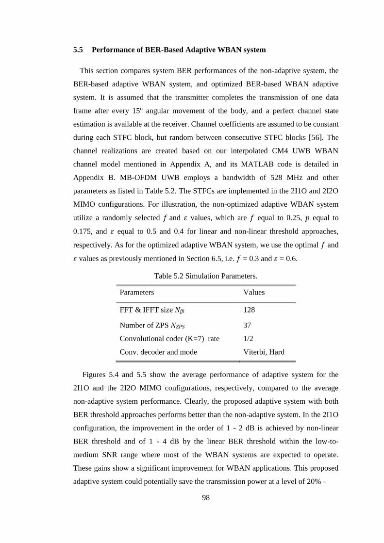
98
5.5 Performance of BER-Based Adaptive WBAN system
This section compares system BER performances of the non-adaptive system, the
BER-based adaptive WBAN system, and optimized BER-based WBAN adaptive
system. It is assumed that the transmitter completes the transmission of one data
frame after every 15o angular movement of the body, and a perfect channel state
estimation is available at the receiver. Channel coefficients are assumed to be constant
during each STFC block, but random between consecutive STFC blocks [56]. The
channel realizations are created based on our interpolated CM4 UWB WBAN
channel model mentioned in Appendix A, and its MATLAB code is detailed in
Appendix B. MB-OFDM UWB employs a bandwidth of 528 MHz and other
parameters as listed in Table 5.2. The STFCs are implemented in the 2I1O and 2I2O
MIMO configurations. For illustration, the non-optimized adaptive WBAN system
utilize a randomly selected 𝑓 and 휀 values, which are 𝑓 equal to 0.25, 𝑝 equal to
0.175, and 휀 equal to 0.5 and 0.4 for linear and non-linear threshold approaches,
respectively. As for the optimized adaptive WBAN system, we use the optimal 𝑓 and
휀 values as previously mentioned in Section 6.5, i.e. 𝑓 = 0.3 and 휀 = 0.6.
Table 5.2 Simulation Parameters.
Parameters Values
FFT & IFFT size Nfft 128
Number of ZPS NZPS 37
Convolutional coder (K=7) rate 1/2
Conv. decoder and mode Viterbi, Hard
Figures 5.4 and 5.5 show the average performance of adaptive system for the
2I1O and the 2I2O MIMO configurations, respectively, compared to the average
non-adaptive system performance. Clearly, the proposed adaptive system with both
BER threshold approaches performs better than the non-adaptive system. In the 2I1O
configuration, the improvement in the order of 1 - 2 dB is achieved by non-linear
BER threshold and of 1 - 4 dB by the linear BER threshold within the low-to-
medium SNR range where most of the WBAN systems are expected to operate.
These gains show a significant improvement for WBAN applications. This proposed
adaptive system could potentially save the transmission power at a level of 20% -
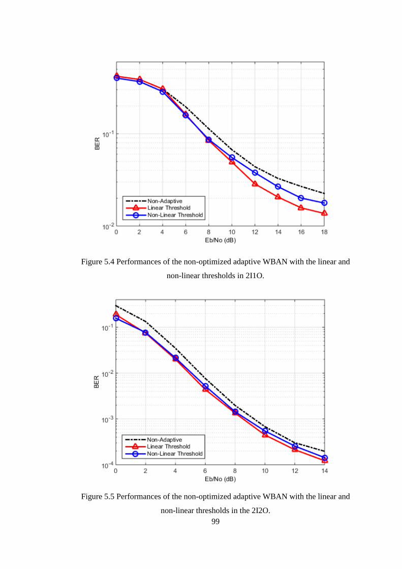
99
Figure 5.4 Performances of the non-optimized adaptive WBAN with the linear and
non-linear thresholds in 2I1O.
Figure 5.5 Performances of the non-optimized adaptive WBAN with the linear and
non-linear thresholds in the 2I2O.
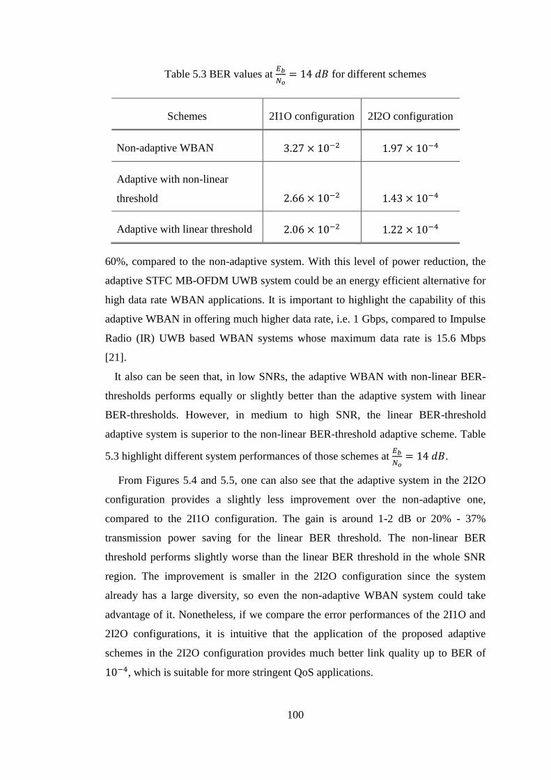
100
Table 5.3 BER values at 𝐸𝑏
𝑁𝑜= 14 𝑑𝐵 for different schemes
Schemes 2I1O configuration 2I2O configuration
Non-adaptive WBAN 3.27 × 10⁻² 1.97 × 10⁻⁴
Adaptive with non-linear
threshold 2.66 × 10⁻² 1.43 × 10⁻⁴
Adaptive with linear threshold 2.06 × 10⁻² 1.22 × 10⁻⁴
60%, compared to the non-adaptive system. With this level of power reduction, the
adaptive STFC MB-OFDM UWB system could be an energy efficient alternative for
high data rate WBAN applications. It is important to highlight the capability of this
adaptive WBAN in offering much higher data rate, i.e. 1 Gbps, compared to Impulse
Radio (IR) UWB based WBAN systems whose maximum data rate is 15.6 Mbps
[21].
It also can be seen that, in low SNRs, the adaptive WBAN with non-linear BER-
thresholds performs equally or slightly better than the adaptive system with linear
BER-thresholds. However, in medium to high SNR, the linear BER-threshold
adaptive system is superior to the non-linear BER-threshold adaptive scheme. Table
5.3 highlight different system performances of those schemes at 𝐸𝑏
𝑁𝑜= 14 𝑑𝐵.
From Figures 5.4 and 5.5, one can also see that the adaptive system in the 2I2O
configuration provides a slightly less improvement over the non-adaptive one,
compared to the 2I1O configuration. The gain is around 1-2 dB or 20% - 37%
transmission power saving for the linear BER threshold. The non-linear BER
threshold performs slightly worse than the linear BER threshold in the whole SNR
region. The improvement is smaller in the 2I2O configuration since the system
already has a large diversity, so even the non-adaptive WBAN system could take
advantage of it. Nonetheless, if we compare the error performances of the 2I1O and
2I2O configurations, it is intuitive that the application of the proposed adaptive
schemes in the 2I2O configuration provides much better link quality up to BER of
10−4, which is suitable for more stringent QoS applications.
101
Figure 5.6 Throughput of the non-optimized adaptive WBAN with the linear and
non-linear thresholds in the 2I1O and 2I2O configurations.
To compare the effects of the linear and non-linear BER thresholds used in the
adaptive algorithm, the average normalized throughput are taken from 24 different
body directions ranging from 0o to 360o as shown in Figure 5.6. Delays of the
channel quality measurement, feedback, and frame transmission are considered
negligible since the distance between the transmitter and the receiver is around 2 - 5
m in a body-to-external WBAN link. Hence, the throughput is not affected by those
delays. At low SNRs, Set-3 with a lower spectral efficiency is most likely employed,
resulting in a lower throughput for both linear and non-linear BER threshold
scenarios. At high SNR values, higher spectral efficiency adaptive schemes, i.e., Set-
1 and Set-2, are employed more frequently, leading to a higher throughput
approaching the non-adaptive throughput of 2 bps/Hz. However, the gap between the
non-adaptive and adaptive throughputs is still significant, even at the high SNR.
From Figure 5.6, one can realize that, within the 𝐸𝑏 𝑁𝑜⁄ range of 0 - 6 dB for
2I1O and 0 - 1 dB for 2I2O, the linear BER threshold approach tends to have a
higher throughput than the non-linear BER threshold. Thus, its BER performance
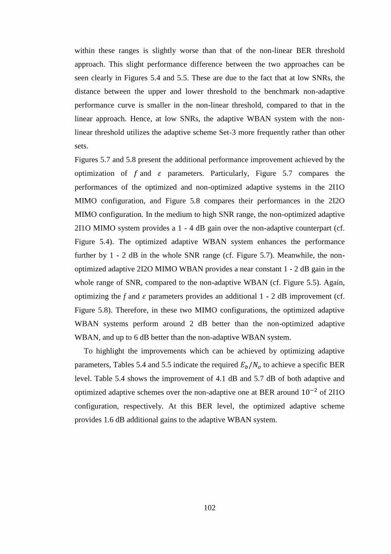
102
within these ranges is slightly worse than that of the non-linear BER threshold
approach. This slight performance difference between the two approaches can be
seen clearly in Figures 5.4 and 5.5. These are due to the fact that at low SNRs, the
distance between the upper and lower threshold to the benchmark non-adaptive
performance curve is smaller in the non-linear threshold, compared to that in the
linear approach. Hence, at low SNRs, the adaptive WBAN system with the non-
linear threshold utilizes the adaptive scheme Set-3 more frequently rather than other
sets.
Figures 5.7 and 5.8 present the additional performance improvement achieved by the
optimization of 𝑓 and 휀 parameters. Particularly, Figure 5.7 compares the
performances of the optimized and non-optimized adaptive systems in the 2I1O
MIMO configuration, and Figure 5.8 compares their performances in the 2I2O
MIMO configuration. In the medium to high SNR range, the non-optimized adaptive
2I1O MIMO system provides a 1 - 4 dB gain over the non-adaptive counterpart (cf.
Figure 5.4). The optimized adaptive WBAN system enhances the performance
further by 1 - 2 dB in the whole SNR range (cf. Figure 5.7). Meanwhile, the non-
optimized adaptive 2I2O MIMO WBAN provides a near constant 1 - 2 dB gain in the
whole range of SNR, compared to the non-adaptive WBAN (cf. Figure 5.5). Again,
optimizing the f and 휀 parameters provides an additional 1 - 2 dB improvement (cf.
Figure 5.8). Therefore, in these two MIMO configurations, the optimized adaptive
WBAN systems perform around 2 dB better than the non-optimized adaptive
WBAN, and up to 6 dB better than the non-adaptive WBAN system.
To highlight the improvements which can be achieved by optimizing adaptive
parameters, Tables 5.4 and 5.5 indicate the required 𝐸𝑏/𝑁𝑜 to achieve a specific BER
level. Table 5.4 shows the improvement of 4.1 dB and 5.7 dB of both adaptive and
optimized adaptive schemes over the non-adaptive one at BER around 10−2 of 2I1O
configuration, respectively. At this BER level, the optimized adaptive scheme
provides 1.6 dB additional gains to the adaptive WBAN system.
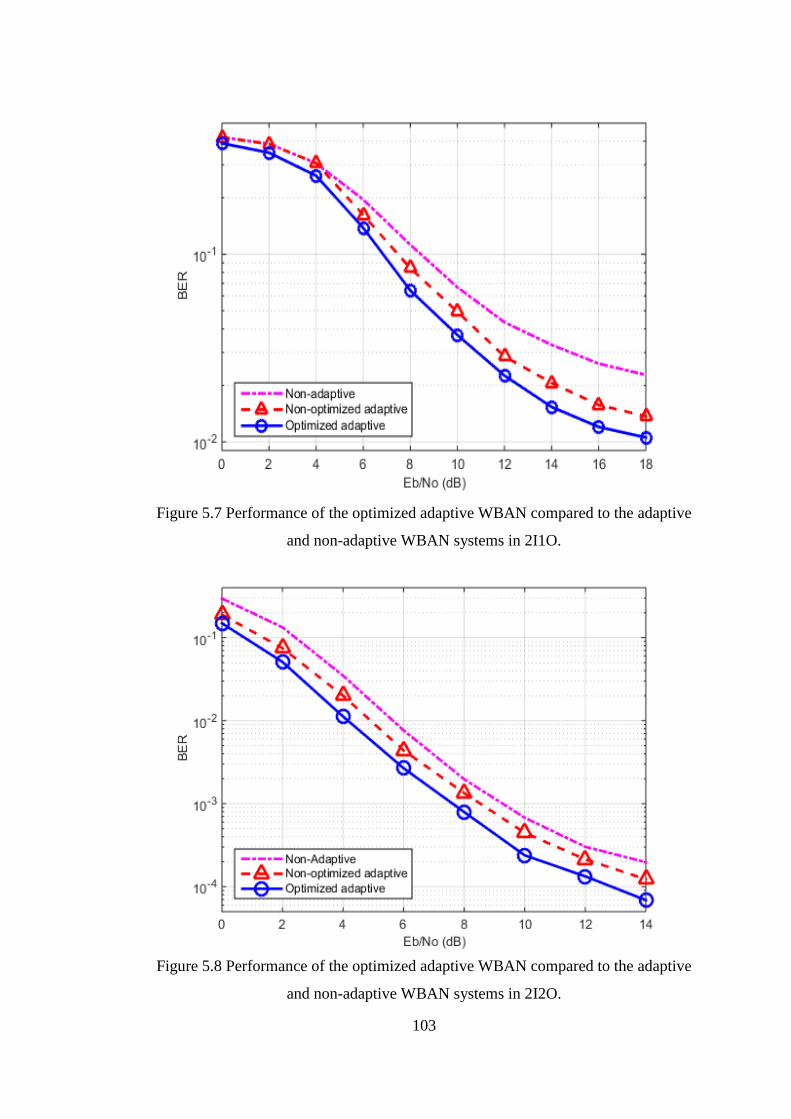
103
Figure 5.7 Performance of the optimized adaptive WBAN compared to the adaptive
and non-adaptive WBAN systems in 2I1O.
Figure 5.8 Performance of the optimized adaptive WBAN compared to the adaptive
and non-adaptive WBAN systems in 2I2O.
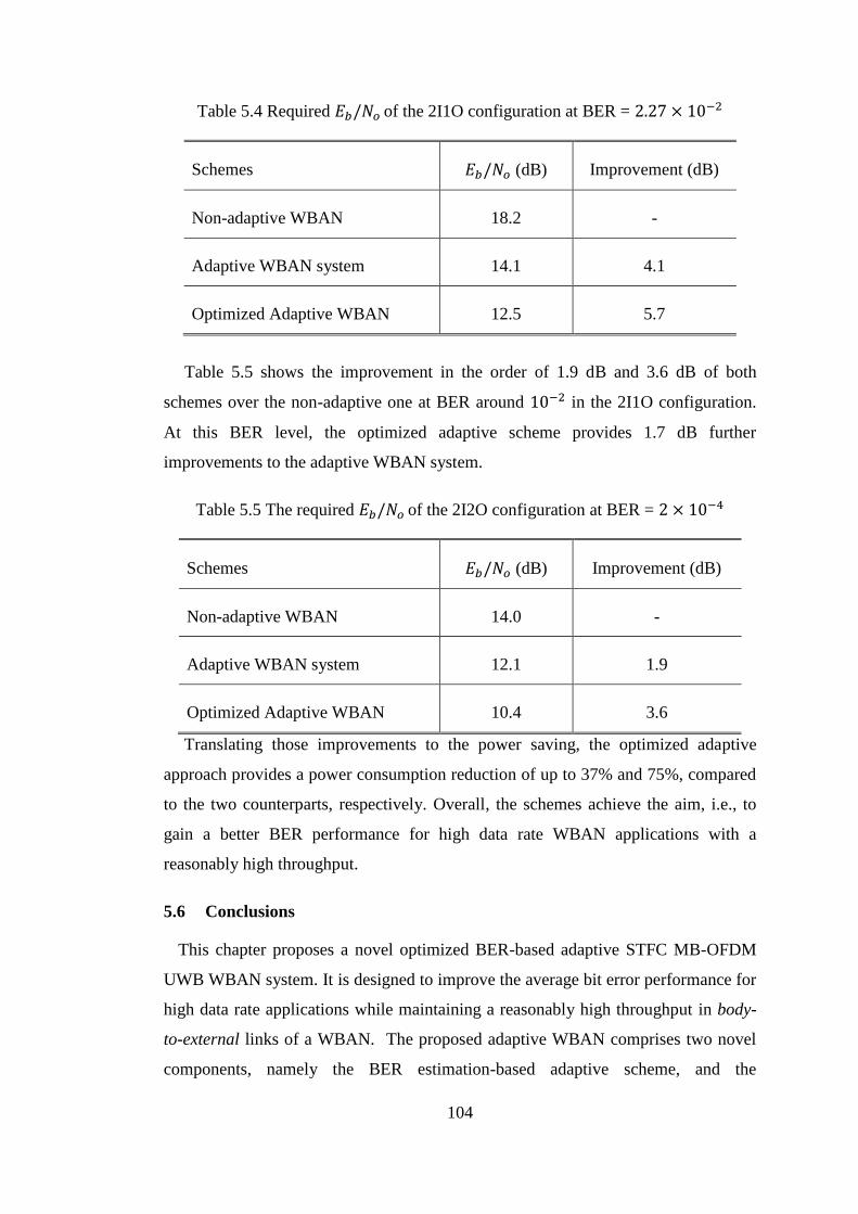
104
Table 5.4 Required 𝐸𝑏/𝑁𝑜 of the 2I1O configuration at BER = 2.27 × 10⁻²
Schemes 𝐸𝑏/𝑁𝑜 (dB) Improvement (dB)
Non-adaptive WBAN 18.2 -
Adaptive WBAN system 14.1 4.1
Optimized Adaptive WBAN 12.5 5.7
Table 5.5 shows the improvement in the order of 1.9 dB and 3.6 dB of both
schemes over the non-adaptive one at BER around 10−2 in the 2I1O configuration.
At this BER level, the optimized adaptive scheme provides 1.7 dB further
improvements to the adaptive WBAN system.
Table 5.5 The required 𝐸𝑏/𝑁𝑜 of the 2I2O configuration at BER = 2 × 10⁻⁴
Schemes 𝐸𝑏/𝑁𝑜 (dB) Improvement (dB)
Non-adaptive WBAN 14.0 -
Adaptive WBAN system 12.1 1.9
Optimized Adaptive WBAN 10.4 3.6
Translating those improvements to the power saving, the optimized adaptive
approach provides a power consumption reduction of up to 37% and 75%, compared
to the two counterparts, respectively. Overall, the schemes achieve the aim, i.e., to
gain a better BER performance for high data rate WBAN applications with a
reasonably high throughput.
5.6 Conclusions
This chapter proposes a novel optimized BER-based adaptive STFC MB-OFDM
UWB WBAN system. It is designed to improve the average bit error performance for
high data rate applications while maintaining a reasonably high throughput in body-
to-external links of a WBAN. The proposed adaptive WBAN comprises two novel
components, namely the BER estimation-based adaptive scheme, and the
105
optimization of its adaptive parameters, i.e., f and 휀 factors, in order to obtain an
extra improvement, hence enhancing the performance further. The adaptive system is
evaluated over the linearly interpolated CM4 UWB WBAN channel with a 10
resolution.
The proposed adaptive WBAN system provides a significant gain of up to 4 dB,
compared to the non-adaptive one. By the optimization of its adaptive parameters (f
and 휀 factors), the system performance could be improved further. Simulation results
show that the proposed optimized adaptive WBAN system can achieve up to 2 dB
gain over the adaptive WBAN, thus providing up to 6 dB gain over the non-adaptive
one. This improvement is equivalent to a reduction of the transmission power by up
to 37% compared to the non-optimized adaptive WBAN, and up to 75% compared to
the non-adaptive WBAN system. The improvements provide critical power reduction
to WBAN devices, thus significantly extending the battery life and enhancing the
reliability of WBAN services. Consequently, the proposed adaptive WBAN system
could be one of feasible effective high speed WBAN platform.
One of important observations from the aforementioned results is the performance
gain which can be used to conserve the transmission power. It is well known, that
due to the limited power sources of WBAN systems, energy efficiency in such a
short range wireless communication plays a pivotal role in the network design
considerations. Thus, it is imperative to investigate the total energy consumption,
including energy consumption in the circuitry, of this proposed adaptive WBAN
system in order to analyze and to maximize its energy efficiency, while maintaining
a satisfactory level of performance. Therefore, the next chapter addresses these issues
with the purpose of demonstrating that the proposed adaptive WBAN scheme is not
only capable of providing an improved bit error performance, but also possesses
better energy efficiency, compared to the non-adaptive one. These features are vital
for enhancing a WBAN network’s lifetime while maintaining a good level of service
quality.
106
CHAPTER 6 ENERGY EFFICIENCY OF ADAPTIVE
WBAN SYSTEMS
6.1 Introduction
This chapter investigates the energy efficiency of the adaptive WBAN system in
both 2I1O and 2I2O MIMO configurations. The chapter considers not only the
transmission power, but also the power consumed in the circuitry. The circuitry
power consists of the rate-independent power consumptions, e.g., power consumed
in the transceiver’s components, such as mixer, filter, Low Noise Amplifier (LNA),
Analog-to-Digital Converter (ADC) and Digital-to-Analog (DAC), and the rate-
dependent power consumption in channel encoders and decoders, including STFC
encoders and decoders [87], [88]. In this thesis, the energy efficiency is measured by
the total energy consumption to transmit the message per bit (TEPB) in (J/b) [88].
The lower TEPB represents better energy efficiency of a communication system. The
energy efficiency of the adaptive WBAN system is evaluated as a function of
distance between a hub and a Wireless Access Point (WAP) in comparison with the
non-adaptive one in the same environment. It is found that the optimized adaptive
WBAN system substantially outperforms the non-adaptive one in terms of energy
efficiency. Furthermore, the relation between energy efficiency and spectral
efficiency of the adaptive WBAN system is also investigated in this chapter. It is
shown that the 2I2O configuration provides a superior performance in terms of
energy efficiency, compared to the 2I1O configuration, at any distance due to its
higher diversity order and its array gain.
The contributions of this chapter are as follows
Investigation and analysis of the energy efficiency model of the proposed
adaptive WBAN system. This includes analysis of the energy efficiency
of every set of adaptive schemes, and analysis and maximization of the
overall energy efficiency of the optimized adaptive WBAN system,
Investigation and analysis of the relation between spectral efficiency and
energy efficiency of the proposed optimized adaptive WBAN system, and
Performance evaluation via simulations of the proposed optimized
adaptive WBAN system in terms of energy efficiency, and in terms of
relation between spectral efficiency and energy efficiency.

107
The content of this chapter has been published in [116].
The structure of this chapter is organized as follows. The analysis of the energy
efficiency of this adaptive system is presented in Section 6.2. Section 6.3 describes
the relation between energy efficiency and spectral efficiency of the adaptive WBAN
system. Numerical evaluations are given in Section 6.4 to illustrate the improvement,
in term of energy efficiency, provided by the proposed adaptive system. Finally,
Section 6.5 concludes the chapter.
6.2 Energy Efficiency Analysis of Adaptive WBAN System
The energy efficiency 𝐸𝑖 associated with the employed adaptive scheme Set-𝑖, 𝑖 ∈
{1,2,3}, is considered as the ratio between the total power consumption and total
transmitted data rate in that scheme [87], [88] as follows
𝐸𝑖 =𝑃𝑇𝑜𝑡,𝑖
𝑅𝑖 (
𝐽𝑜𝑢𝑙𝑒
𝑏𝑖𝑡) (6.1)
where 𝑃𝑇𝑜𝑡,𝑖 and 𝑅𝑖 are the total power consumption and transmitted data rate in the
scheme Set-𝑖, respectively. Note that 𝑅𝑖 is equal to 𝐵Γ𝑖, where Γ𝑖 is the spectral
efficiency (or normalized capacity) in bps/Hz of the scheme Set-𝑖 and 𝐵 is the system
bandwidth. The total power consumed during transmission of the data rate 𝑅𝑖
consists of the power dissipated in the circuitry 𝑃𝐶,𝑖 and power consumed in the
power amplifier (PA) 𝑃𝑃𝐴,𝑖. Let us assume that 𝑃𝐶 comprises a rate-independent
power 𝑃, which is consumed in the parts of the transceiver, including adaptive
modulation and power control, and a rate-dependent power 𝑃(𝑅𝑖) that is dissipated,
for instance, in the channel encoder/decoder and STFC encoder/decoder. 𝑃(𝑅𝑖) is
assumed to increase linearly with 𝑅𝑖, i.e. 𝑃(𝑅𝑖)~𝜗𝑅𝑖, where 𝜗 is a constant [88].
Then, the circuitry’s power is
𝑃𝐶,𝑖 = 𝑃 + 𝜗𝑅𝑖 (6.2)
The power dissipated in the amplifier in order to transmit the data rate 𝑅𝑖 is
𝑃𝑃𝐴,𝑖 = (𝜉
𝜂⁄ ) × 𝑃𝑇,𝑖 (6.3)
108
where 𝜉 is the peak-to-average power ratio (PAPR), 𝜂 is the drain efficiency of the
power amplifier, and 𝑃𝑇,𝑖 is the average transmission power. Then the total power
consumption is
𝑃𝑇𝑜𝑡,𝑖 = 𝑃𝐶,𝑖 + 𝑃𝑃𝐴,𝑖 = 𝑃 + 𝜗𝑅𝑖 + (𝜉
𝜂⁄ ) × 𝑃𝑇,𝑖 (6.4)
For simplicity, it is assumed that the path loss 𝑃𝐿𝑖 between transmitter and receiver
associated with the scheme Set-𝑖 follows a log normal distribution [112]
𝑃𝐿𝑖 (𝑑𝐵) = 𝑃𝐿𝑜 + 10𝑛𝑖 log10
𝑑
𝑑𝑜+ 𝑆𝑖 (6.5)
where 𝑃𝐿𝑜 is the path loss at the reference point 𝑑𝑜, 𝑛𝑖 is the path loss exponent of
the link, and 𝑆𝑖 (dB) is the shadowing component of the link, which is a zero mean
Gaussian random variable with a standard deviation 𝜎𝑖. The instantaneous Signal to
Noise Ratio (SNR) at the receive antenna is 𝛽𝑖 =𝑃𝑅,𝑖
𝑃𝑁,𝑖, where 𝑃𝑅,𝑖 is the received
signal power, and 𝑃𝑁,𝑖 = 𝑁𝑜𝐵𝑁𝑓 is the total noise power at the receiver in this link
[112]. 𝑁𝑜 = 174 𝑑𝐵𝑚/𝐻𝑧 is the two sided noise spectral density [74], [112], and 𝑁𝑓
is the noise figure. If �̅�𝑖 is the average SNR at the receive antenna to achieve a
targeted symbol error rate (SER) in the link-𝑖, then the average transmit power �̅�𝑇,𝑖 to
satisfy this requirement is depended on the average received power �̅�𝑅,𝑖 and the path
loss experienced by the link as defined by
�̅�𝑇,𝑖 = �̅�𝑅,𝑖 (10(
𝑃𝐿𝑜10
)
𝑑𝑜𝑛𝑖
)𝑑𝑛𝑖10(𝑆𝑖10
) (6.6)
From equations (6.1), (6.4), and (6.6), the energy efficiency of the link-𝑖 𝐸𝑖 is defined
as follow
𝐸𝑖 =𝑃 + 𝜗𝑅𝑖
𝑅𝑖+ (
𝜉𝜂⁄ )
�̅�𝑅,𝑖
𝑅𝑖(10(
𝑃𝐿𝑜10
)
𝑑𝑜𝑛𝑖
)𝑑𝑛𝑖10(𝑆𝑖10
) (6.7)
109
The first part of 𝐸𝑖 is the circuitry energy consumption per bit, and the second part is
the transmission energy per bit. With little manipulation, (6.7) can be rewritten as a
function of �̅�𝑖 as below
𝐸𝑖 =𝑃 + 𝜗𝑅𝑖
𝑅𝑖+ (
𝜉𝜂⁄ )
�̅�𝑖𝑁𝑜𝐵𝑁𝑓
𝑅𝑖(10(
𝑃𝐿𝑜10
)
𝑑𝑜𝑛𝑖
)𝑑𝑛𝑖10(𝑆𝑖10
) (6.8)
As aforementioned, the adaptive WBAN system employs three sets of adaptive
schemes, Set-𝑖, 𝑖 ∈ {1,2, 3}. Those adaptive schemes will be evaluated in the 2I1O
and 2I2O MIMO configurations. Let us assume that perfect channel knowledge is
known at the receiver, but unknown to the transmitter. A maximum likelihood
detector is employed at the receiver. The SNR 𝛾𝑖 at the input of the detector is [56],
[57]
𝛾𝑖 =1
𝐷∑|ℎ𝑚|2𝛽𝑖
ℳ
𝑚=1
(6.9)
where ℳ is the maximum number of channels between the transmitter and the
receiver, and ℎ𝑚 is the channel gain. The symbol error probability 𝑃𝑒,𝑖 at the detector
is [56], [74]
𝑃𝑒,𝑖 = �̅�𝑒,𝑖𝑄(√𝛾𝑖𝑑𝑚𝑖𝑛,𝑖
2
2) (6.10)
where �̅�𝑒,𝑖 is the number of neighbourhoods in the modulation constellation, and
𝑑𝑚𝑖𝑛,𝑖 is the minimum Euclidean distance of the signal constellation, respectively.
By applying a Chernoff bound, i.e. 𝑄(𝑥) ≤ 𝑒−𝑥2
2⁄ , the upper bound of (6.10) is
obtained as follows [56]
𝑃𝑒,𝑖 ≤ �̅�𝑒,𝑖𝑒−(∑ |ℎ𝑚|2ℳ
𝑚=1 )𝛽𝑖𝑑𝑚𝑖𝑛,𝑖2
4ℳ (6.11)
Assuming ℎ𝑚 is an independent zero-mean circulant symmetric complex Gaussian
(ZMCSCG), then the average symbol error probability �̅�𝑒,𝑖 is the expected values of
𝑃𝑒,𝑖, i.e., �̅�𝑒,𝑖 = 𝐸{𝑃𝑒,𝑖} which is upper bounded by [56]

110
�̅�𝑒,𝑖 ≤ �̅�𝑒,𝑖 ∏1
1 +𝛽𝑖𝑑𝑚𝑖𝑛,𝑖
2
4ℳ
ℳ
𝑖=1
(6.12)
6.2.1 Energy Efficiency of the 2I1O Configuration
In this configuration, the numbers of transmit antennas 𝑀 and receive antennas 𝑁
are equal to 2 and 1, respectively. Thus, the maximum number of channels between
the transmitter and receiver is ℳ = 𝑀 = 2. In a high SNR region (𝛽𝑖 ≫ 1), the
average symbol error probability of this MIMO configuration in (6.12) becomes
�̅�𝑒,𝑖 ≤ �̅�𝑒,𝑖 (𝛽𝑖𝑑𝑚𝑖𝑛,𝑖
2
8)
−2
(6.13)
Set-1 and Set-2:
Set-1 utilizes the QPSK modulation and the Sezginer-Sari code, and Set-2
employs the QPSK modulation and the Alamouti code. In both sets, �̅�𝑒,𝑖 = 2, and
𝑑𝑚𝑖𝑛,𝑖 = √2. Therefore, from (6.13), the upper bound of symbol error probability is
�̅�𝑒,𝑖 ≤ 2
(
(�̅�𝑅,𝑖
𝑅𝑖)
4𝑁𝑜
)
−2
(6.14)
where 𝑖 ∈ {1,2}. Therefore, the average power at the receive antenna required to
achieve a target SER �̅�𝑒,𝑖 is
�̅�𝑅,𝑖 =4𝑅𝑖𝑁𝑜
√0.5�̅�𝑒,𝑖
(6.15)
By substituting (6.15) into (6.7), the energy efficiency for Set-1 and Set-2 in this
2I1O configuration for the target SER �̅�𝑒,𝑖 is
𝐸𝑖=1,2 =𝑃 + 𝜗𝑅𝑖
𝑅𝑖+ (
𝜉𝜂⁄ )
4𝑁𝑜
√0.5�̅�𝑒,𝑖
(10(
𝑃𝐿𝑜10
)
𝑑𝑜𝑛𝑖
)𝑑𝑛𝑖10(𝑆𝑖10
) (6.16)
111
Set-3:
Set-3 employs the BPSK modulation and the Alamouti code. It is assumed that an
antipodal signal is used for the BPSK modulation. This means �̅�𝑒,𝑖 = 1 and 𝑑𝑚𝑖𝑛,𝑖 =
2. In a high SNR region (𝛽𝑖 ≫ 1), the upper bound of the average probability of
symbol errors in (6.12) becomes
�̅�𝑒,𝑖 ≤ ((�̅�𝑅,𝑖𝑅𝑖
)
2𝑁𝑜)
−2
(6.17)
Here, 𝑖 ∈ {3}. The average received power required for the target SER �̅�𝑒,𝑖 is
�̅�𝑅,𝑖 =2𝑅𝑖𝑁𝑜
√�̅�𝑒,𝑖
(6.18)
Energy efficiency of Set-3 in this MIMO configuration can be found by applying
(6.18) to (6.7) and equivalent to
𝐸𝑖=3 =𝑃 + 𝜗𝑅𝑖
𝑅𝑖+ (
𝜉𝜂⁄ )
2𝑁𝑜
√�̅�𝑒,𝑖
(10(
𝑃𝐿𝑜10
)
𝑑𝑜𝑛𝑖
)𝑑𝑛𝑖10(𝑆𝑖10
) (6.19)
6.2.2 Energy Efficiency of the 2I2O Configuration
In this configuration, the maximum number of links between the transmitter and
receiver ℳ = 𝑀 = 𝑁 = 2. In a high SNR region (𝛽𝑖 ≫ 1), the average symbol error
probability becomes [56]
�̅�𝑒,𝑖 ≤ �̅�𝑒,𝑖 (𝛽𝑖𝑑𝑚𝑖𝑛,𝑖
2
4𝑀)
−𝑀𝑁
≤ �̅�𝑒,𝑖 (𝛽𝑖𝑑𝑚𝑖𝑛,𝑖
2
8)
−4
(6.20)
Set-1 and Set-2:
Using the same method mentioned in Sub-section 6.2.1, the upper bound of the
average symbol error rate is given by

112
�̅�𝑒,𝑖 ≤ 2
(
(�̅�𝑅,𝑖
𝑅𝑖)
4𝑁𝑜
)
−4
(6.21)
where 𝑖 ∈ {1,2}. Thus, the average power at the receive antenna required to achieve
the target SER �̅�𝑒,𝑖 in these schemes is provided as
�̅�𝑅,𝑖 =4𝑅𝑖𝑁𝑜
√0.5�̅�𝑒,𝑖4
(6.22)
By replacing (6.22) in (6.7), the energy efficiency for Set-1 and Set-2 in this 2I2O
configuration is
𝐸𝑖=1,2 =𝑃+𝜗𝑅𝑖
𝑅𝑖+ (
𝜉𝜂⁄ )
4𝑁𝑜
√0.5�̅�𝑒,𝑖4
(10
(𝑃𝐿𝑜10
)
𝑑𝑜𝑛𝑖
)𝑑𝑛𝑖10(𝑆𝑖10
) (6.23)
Set-3:
Using the same methods mentioned in Sub-section 6.2.1, the upper bound of the
average symbol error rate is
�̅�𝑒,𝑖 ≤
(
(�̅�𝑅,𝑖
𝑅𝑖)
2𝑁𝑜
)
−4
(6.24)
where 𝑖 ∈ {3}. The average power at the receive antenna required for the target SER
�̅�𝑒,𝑖 is
�̅�𝑅,𝑖 =2𝑅𝑖𝑁𝑜
√�̅�𝑒,𝑖4
(6.25)
The energy efficiency of Set-3 is found by applying (6.25) to (6.7)
𝐸𝑖=3 =𝑃+𝜗𝑅𝑖
𝑅𝑖+ (
𝜉𝜂⁄ )
2𝑁𝑜
√�̅�𝑒,𝑖4
(10
(𝑃𝐿𝑜10
)
𝑑𝑜𝑛𝑖
)𝑑𝑛𝑖10(𝑆𝑖10
) (6.26)
113
6.2.3 Energy Efficiency of the Adaptive WBAN System
As mentioned in detail in Chapter 5 (and [110-111]), in the optimized adaptive
system, one set of adaptive schemes is employed over a portion of a frame, which
could possibly change to a different scheme for the transmission of the remaining
part of that frame. During transmission of the 𝑞𝑡ℎ frame, where 𝑞 = 0, 1, 2, … , 𝑄 − 1,
and 𝑄 is the number of frames, a full body rotation, i.e., 360𝑜, may generate several
frame transmissions, depending on the rotation speed. Performance of the adaptive
system in terms of energy efficiency depends on the selected adaptive scheme Set-𝑖
on a frame-to-frame basis. Denote the connectivity between a body worn transceiver
(or hub) and the external access point at a certain body direction (or in the associated
link 𝑖) and the 𝑞𝑡ℎ frame as 𝐶𝑖𝑞, we have
𝐶𝑖𝑞 = {
1, if Set 𝑖 is selected on the 𝑞𝑡ℎ frame 0, otherwise
(6.27)
The transmitted data rate 𝑅𝑖𝑞 in the associated link 𝑖 and the 𝑞𝑡ℎ frame is determined
by
𝑅𝑖𝑞 ≤ 𝐵Γ𝑖
𝑞 (6.28)
where Γ𝑖𝑞 is the spectral efficiency of Set-𝑖 of the 𝑞𝑡ℎ frame, and 𝐵 is the system
bandwidth. Thus, the average energy efficiency per frame, �̅�𝑇, of the adaptive
WBAN system is calculated as
�̅�𝑇 =1
𝑄∑ ∑𝐶𝑖
𝑞𝐸𝑖𝑞
3
𝑖
𝑄−1
𝑞=0
= 1
𝑄∑ ∑𝐶𝑖
𝑞 𝑃𝑇𝑜𝑡(Γ𝑖𝑞)
𝐵Γ𝑖𝑞
3
𝑖
𝑄−1
𝑞=0
(6.29)
where 𝐸𝑖𝑞 is the energy efficiency of Set-𝑖 of the 𝑞𝑡ℎ frame.
In order to maximize the energy efficiency of the system, given the symbol error
rate (SER) not exceeding the target SER, the adaptive WBAN scheme is to be
selected appropriately. It is worth to mention the difference between optimization of
adaptive WBAN system in Section 5.4, and the optimization in term of energy
efficiency here. The former was done based on the BER performance to find the
optimum f and 휀 factors. Whereas, the latter is carried out on the already optimized
adaptive WBAN system (c.f. Section 5.4) in order to maximize the energy efficiency

114
of an adaptive WBAN implementation. The optimization is conducted by selecting
an adaptive scheme from three possible schemes which generates the minimum
energy consumption to be employed in the current frame and each subsequent frame,
given the target SER is met. Thus, this optimization process is equivalent to
minimizing the average energy consumption per frame �̅�𝑇 as follow
min𝑖∈{1,2,3}
�̅�𝑇 = min𝑖∈{1,2,3}
1
𝑄∑ ∑𝐶𝑖
𝑞 𝑃𝑇𝑜𝑡(Γ𝑖𝑞)
𝐵Γ𝑖𝑞
3
𝑖
𝑄−1
𝑞=0
(6.30)
s.t.
∑𝐶𝑖𝑞
𝑖
= 1, ∀ 𝑖 ∈ {1,2,3}, 𝐶𝑖𝑞 ∈ [0,1] (6.31)
Γ𝑖𝑞 ∈ Γ,where Γ = {1,2,3} (6.32)
∑ ∑�̅�𝑇𝑅𝑖𝑞
3
𝑖=1
𝑄−1
𝑞=0
≤ available energy (6.33)
From (6.30) it can be seen that min𝑖∈{1,2,3}
�̅�𝑇 can be found by selecting the minimum
value of ∑ 𝐶𝑖𝑞 𝑃𝑇𝑜𝑡(Γ𝑖
𝑞)
𝐵Γ𝑖𝑞
3𝑖=1 in each frame transmission. In other words, maximizing the
average energy efficiency of the adaptive WBAN system is equivalent to selecting an
adaptive scheme with the minimum energy consumption to be employed in the
current frame and each subsequent frame, given the target SER is met. Because there
are only three possible adaptive schemes to choose from in every frame transmission
as given by the constraint in (6.32), thus the exhaustive search can be utilized
without implying a hefty computational load [114]. For instance, when channel
exhibits a specific SNR or BER, the adaptive algorithm select the most energy-
efficient adaptive scheme by comparing the least total energy consumed by each of
the three possible Set-𝑖, given its spectral efficiency (hence, the capacity) is known.
It is important to note that the total energy consumed for transmission of all frames
must not exceed the available energy provided by the energy resource (e.g. battery),
as given by Eq. (6.33).
115
6.3 Relation between Energy Efficiency and Spectral Efficiency in Adaptive
WBAN System
Energy efficiency is a critical issue in WBAN design due to limited power
resources of WBAN devices or nodes and impracticality to replace batteries
frequently, particularly the implant nodes. As a matter of fact, increasing energy
efficiency always conflicts with improving spectral efficiency [56], [74]. Therefore,
energy efficiency and spectral efficiency cannot be optimized simultaneously [74].
Luckily the proposed adaptive WBAN system has high capacity, compared to the
capacity requirement of the current and foreseeable future WBAN applications [109-
111]. Therefore, in Chapter 6 (see also [109-111]), we have optimized the BER
performance of the proposed adaptive WBAN system, given the capacity as
constraint, without taking the energy consumption issue into consideration. This
optimization gave us a favorable BER performance compared to the performance of
the non-adaptive WBAN system.
The following sections provide further performance analysis of the proposed
adaptive WBAN system from the energy efficiency perspective in relation to its
spectral efficiency, which has not been considered so far in this thesis.
6.3.1 Energy Efficiency vs Spectral Efficiency in 2I1O Configuration
The spectral efficiency of the 2I1O configuration in bps/Hz when the channel
coefficients are unknown to the transmitter [56 Eq. (4.30)] is
Γ2I1O = log2 (1 +𝐸𝑠
𝑀𝑁𝑜
‖𝒉‖𝐹2) (6.34)
where 𝒉 is the channel vector, and ‖∙‖𝐹 is the Frobenius operation. ‖𝒉‖𝐹2 is assumed
to be equal 1 [56]. From the link budget G = 1/PL (i.e. 𝐺 (𝑑𝐵) = −𝑃𝐿 (𝑑𝐵)),
following Eq. (6.5) and using the relation in (6.3) and (6.6), (6.34) can be rewritten
as
Γ2I1O = log2 (1 +𝐺 (
𝜂𝜉⁄ ) 𝑃𝑃𝐴
𝑀𝐵𝑁𝑜) (6.35)

116
Denote Γ2I1O = Γ𝑖, then from (6.35), we have 𝑃𝑃𝐴 =𝑀𝐵𝑁𝑜
𝐺(𝜉
𝜂⁄ ) (2Γ𝑖 − 1). Thus,
the energy efficiency as a function of the spectral efficiency of the adaptive WBAN
system in the 2I1O configuration can be found by applying (6.35) to (6.1) and (6.5)
𝐸𝑖,2I1O(Γ𝑖) = 𝑃 + 𝜗𝐵Γ𝑖
𝐵Γ𝑖+
𝑀𝑁𝑜
𝐺(𝜉
𝜂⁄ )(2Γ𝑖 − 1)
Γ𝑖 (6.36)
6.3.2 Energy Efficiency vs Spectral Efficiency in 2I2O configuration
The maximum spectral efficiency of orthogonal 2I2O channels in bps/Hz when
the channel coefficients are unknown to the transmitter [56, Eq. (4.33)] is
Γ2I2O = ℳlog2 (1 +𝐸𝑠
𝑁𝑜) (6.37)
where ℳ = 𝑀 = 𝑁. From the link budget, the spectral efficiency of 2I2O is
Γ2I2O = 𝑀log2 (1 +𝐺 (
𝜂𝜉⁄ ) 𝑃𝑃𝐴
𝐵𝑁𝑜) (6.38)
Denote Γ2I2O = Γ𝑖, from (6.38), we have 𝑃𝑃𝐴 =𝐵𝑁𝑜
𝐺(𝜉
𝜂⁄ ) (2Γ𝑖
𝑀⁄ − 1). As a result,
the energy efficiency as a function of spectral efficiency of the adaptive WBAN
system in the 2I2O configuration can be found by applying (6.38) to (6.1) and (6.5)
𝐸𝑖,2I2O(Γ𝑖) = 𝑃 + 𝜗𝐵Γ𝑖
𝐵Γ𝑖+
𝑁𝑜
𝐺(𝜉
𝜂⁄ )(2
Γ𝑖𝑀 − 1)
Γ𝑖 (6.39)
6.4 Numerical Results
In this section, a numerical evaluation is provided to assess how well the proposed
adaptive WBAN system performs in terms of energy efficiency. As stated before, the
energy efficiency is measured by the energy consumption per bit, in (J/bit), on a
frame-to-frame basis, either for transmission energy only or the total energy
consumption of the system. This energy consumption per bit is frame independent,
i.e. not depending on the frame size (c.f. Section 6.2.3). Accordingly, higher energy
consumption per bit means a less energy-efficient system.
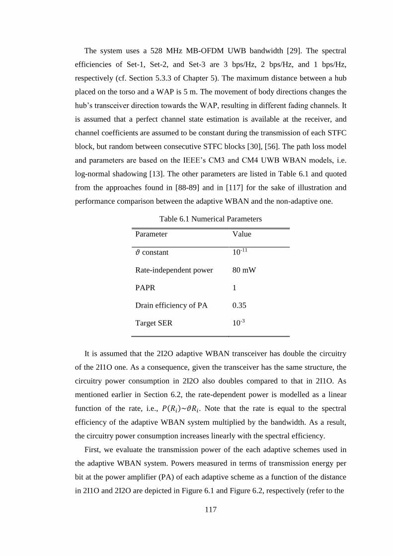
117
The system uses a 528 MHz MB-OFDM UWB bandwidth [29]. The spectral
efficiencies of Set-1, Set-2, and Set-3 are 3 bps/Hz, 2 bps/Hz, and 1 bps/Hz,
respectively (cf. Section 5.3.3 of Chapter 5). The maximum distance between a hub
placed on the torso and a WAP is 5 m. The movement of body directions changes the
hub’s transceiver direction towards the WAP, resulting in different fading channels. It
is assumed that a perfect channel state estimation is available at the receiver, and
channel coefficients are assumed to be constant during the transmission of each STFC
block, but random between consecutive STFC blocks [30], [56]. The path loss model
and parameters are based on the IEEE’s CM3 and CM4 UWB WBAN models, i.e.
log-normal shadowing [13]. The other parameters are listed in Table 6.1 and quoted
from the approaches found in [88-89] and in [117] for the sake of illustration and
performance comparison between the adaptive WBAN and the non-adaptive one.
Table 6.1 Numerical Parameters
Parameter Value
𝜗 constant 10-11
Rate-independent power 80 mW
PAPR 1
Drain efficiency of PA 0.35
Target SER 10-3
It is assumed that the 2I2O adaptive WBAN transceiver has double the circuitry
of the 2I1O one. As a consequence, given the transceiver has the same structure, the
circuitry power consumption in 2I2O also doubles compared to that in 2I1O. As
mentioned earlier in Section 6.2, the rate-dependent power is modelled as a linear
function of the rate, i.e., 𝑃(𝑅𝑖)~𝜗𝑅𝑖. Note that the rate is equal to the spectral
efficiency of the adaptive WBAN system multiplied by the bandwidth. As a result,
the circuitry power consumption increases linearly with the spectral efficiency.
First, we evaluate the transmission power of the each adaptive schemes used in
the adaptive WBAN system. Powers measured in terms of transmission energy per
bit at the power amplifier (PA) of each adaptive scheme as a function of the distance
in 2I1O and 2I2O are depicted in Figure 6.1 and Figure 6.2, respectively (refer to the

118
Figure 6.1 Transmission energy per bit of each adaptive scheme as a function of
distance between the hub and the WAP in the 2I1O configuration.
Figure 6.2 Transmission energy per bit of each adaptive schemes as a function of
distance between the hub and the WAP in the 2I2O configuration.
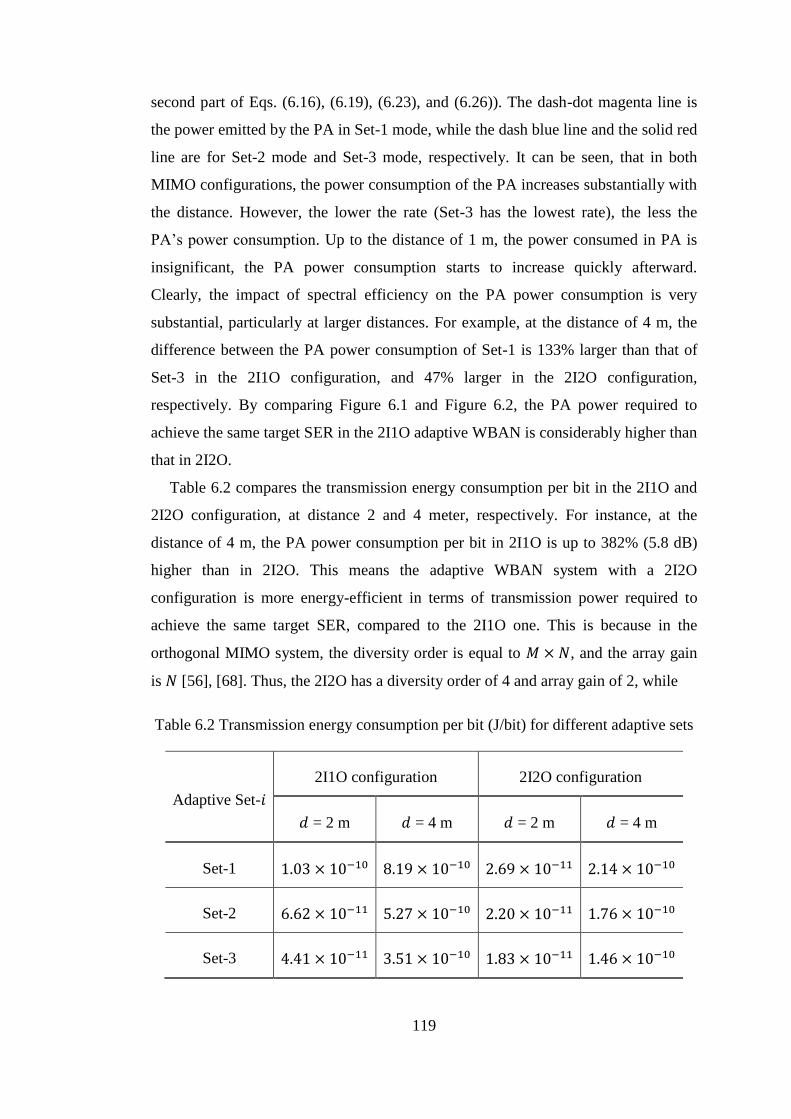
119
second part of Eqs. (6.16), (6.19), (6.23), and (6.26)). The dash-dot magenta line is
the power emitted by the PA in Set-1 mode, while the dash blue line and the solid red
line are for Set-2 mode and Set-3 mode, respectively. It can be seen, that in both
MIMO configurations, the power consumption of the PA increases substantially with
the distance. However, the lower the rate (Set-3 has the lowest rate), the less the
PA’s power consumption. Up to the distance of 1 m, the power consumed in PA is
insignificant, the PA power consumption starts to increase quickly afterward.
Clearly, the impact of spectral efficiency on the PA power consumption is very
substantial, particularly at larger distances. For example, at the distance of 4 m, the
difference between the PA power consumption of Set-1 is 133% larger than that of
Set-3 in the 2I1O configuration, and 47% larger in the 2I2O configuration,
respectively. By comparing Figure 6.1 and Figure 6.2, the PA power required to
achieve the same target SER in the 2I1O adaptive WBAN is considerably higher than
that in 2I2O.
Table 6.2 compares the transmission energy consumption per bit in the 2I1O and
2I2O configuration, at distance 2 and 4 meter, respectively. For instance, at the
distance of 4 m, the PA power consumption per bit in 2I1O is up to 382% (5.8 dB)
higher than in 2I2O. This means the adaptive WBAN system with a 2I2O
configuration is more energy-efficient in terms of transmission power required to
achieve the same target SER, compared to the 2I1O one. This is because in the
orthogonal MIMO system, the diversity order is equal to 𝑀 × 𝑁, and the array gain
is 𝑁 [56], [68]. Thus, the 2I2O has a diversity order of 4 and array gain of 2, while
Table 6.2 Transmission energy consumption per bit (J/bit) for different adaptive sets
Adaptive Set-𝑖
2I1O configuration 2I2O configuration
𝑑 = 2 m 𝑑 = 4 m 𝑑 = 2 m 𝑑 = 4 m
Set-1 1.03 × 10⁻¹⁰ 8.19 × 10⁻¹⁰ 2.69 × 10⁻¹¹ 2.14 × 10⁻¹⁰
Set-2 6.62 × 10⁻¹¹ 5.27 × 10⁻¹⁰ 2.20 × 10⁻¹¹ 1.76 × 10⁻¹⁰
Set-3 4.41 × 10⁻¹¹ 3.51 × 10⁻¹⁰ 1.83 × 10⁻¹¹ 1.46 × 10⁻¹⁰
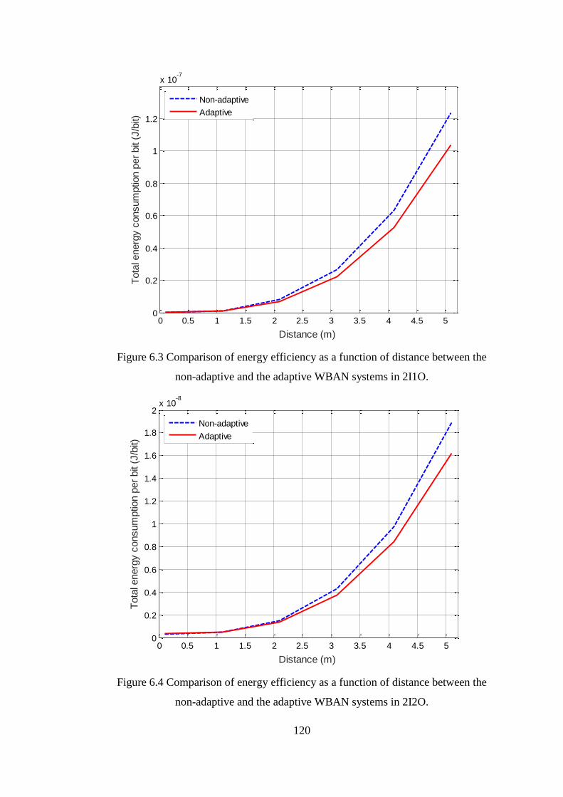
120
Figure 6.3 Comparison of energy efficiency as a function of distance between the
non-adaptive and the adaptive WBAN systems in 2I1O.
Figure 6.4 Comparison of energy efficiency as a function of distance between the
non-adaptive and the adaptive WBAN systems in 2I2O.
0 0.5 1 1.5 2 2.5 3 3.5 4 4.5 50
0.2
0.4
0.6
0.8
1
1.2
x 10-7
Distance (m)
Tota
l energ
y c
onsum
ptio
n p
er
bit
(J/b
it)
Non-adaptive
Adaptive
0 0.5 1 1.5 2 2.5 3 3.5 4 4.5 50
0.2
0.4
0.6
0.8
1
1.2
1.4
1.6
1.8
2x 10
-8
Distance (m)
Tota
l energ
y c
onsum
ptio
n p
er
bit
(J/b
it)
Non-adaptive
Adaptive
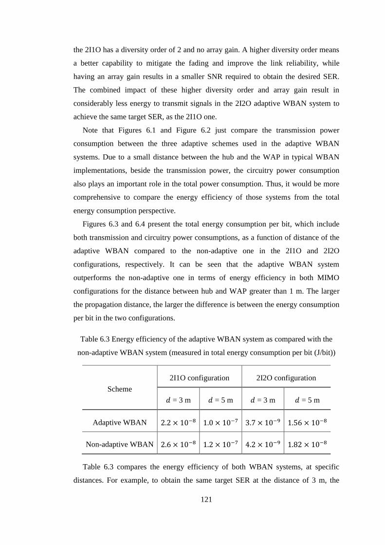
121
the 2I1O has a diversity order of 2 and no array gain. A higher diversity order means
a better capability to mitigate the fading and improve the link reliability, while
having an array gain results in a smaller SNR required to obtain the desired SER.
The combined impact of these higher diversity order and array gain result in
considerably less energy to transmit signals in the 2I2O adaptive WBAN system to
achieve the same target SER, as the 2I1O one.
Note that Figures 6.1 and Figure 6.2 just compare the transmission power
consumption between the three adaptive schemes used in the adaptive WBAN
systems. Due to a small distance between the hub and the WAP in typical WBAN
implementations, beside the transmission power, the circuitry power consumption
also plays an important role in the total power consumption. Thus, it would be more
comprehensive to compare the energy efficiency of those systems from the total
energy consumption perspective.
Figures 6.3 and 6.4 present the total energy consumption per bit, which include
both transmission and circuitry power consumptions, as a function of distance of the
adaptive WBAN compared to the non-adaptive one in the 2I1O and 2I2O
configurations, respectively. It can be seen that the adaptive WBAN system
outperforms the non-adaptive one in terms of energy efficiency in both MIMO
configurations for the distance between hub and WAP greater than 1 m. The larger
the propagation distance, the larger the difference is between the energy consumption
per bit in the two configurations.
Table 6.3 Energy efficiency of the adaptive WBAN system as compared with the
non-adaptive WBAN system (measured in total energy consumption per bit (J/bit))
Scheme
2I1O configuration 2I2O configuration
𝑑 = 3 m 𝑑 = 5 m 𝑑 = 3 m 𝑑 = 5 m
Adaptive WBAN 2.2 × 10⁻⁸ 1.0 × 10⁻⁷ 3.7 × 10⁻⁹ 1.56 × 10⁻⁸
Non-adaptive WBAN 2.6 × 10⁻⁸ 1.2 × 10⁻⁷ 4.2 × 10⁻⁹ 1.82 × 10⁻⁸
Table 6.3 compares the energy efficiency of both WBAN systems, at specific
distances. For example, to obtain the same target SER at the distance of 3 m, the
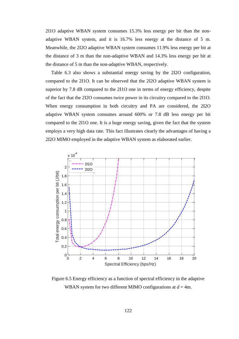
122
2I1O adaptive WBAN system consumes 15.3% less energy per bit than the non-
adaptive WBAN system, and it is 16.7% less energy at the distance of 5 m.
Meanwhile, the 2I2O adaptive WBAN system consumes 11.9% less energy per bit at
the distance of 3 m than the non-adaptive WBAN and 14.3% less energy per bit at
the distance of 5 m than the non-adaptive WBAN, respectively.
Table 6.3 also shows a substantial energy saving by the 2I2O configuration,
compared to the 2I1O. It can be observed that the 2I2O adaptive WBAN system is
superior by 7.8 dB compared to the 2I1O one in terms of energy efficiency, despite
of the fact that the 2I2O consumes twice power in its circuitry compared to the 2I1O.
When energy consumption in both circuitry and PA are considered, the 2I2O
adaptive WBAN system consumes around 600% or 7.8 dB less energy per bit
compared to the 2I1O one. It is a huge energy saving, given the fact that the system
employs a very high data rate. This fact illustrates clearly the advantages of having a
2I2O MIMO employed in the adaptive WBAN system as elaborated earlier.
Figure 6.5 Energy efficiency as a function of spectral efficiency in the adaptive
WBAN system for two different MIMO configurations at d = 4m.
0 2 4 6 8 10 12 14 16 18 200
0.2
0.4
0.6
0.8
1
1.2
1.4
1.6
1.8
2
x 10-8
Spectral Efficiency (bps/Hz)
Tota
l energ
y c
onsum
ptio
n p
er
bit
(J/b
it)
2I1O
2I2O

123
Figure 6.5 shows the relation between energy consumption per bit and spectral
efficiency of the adaptive WBAN system with 2I1O and 2I2O configurations at the
fixed distance d = 4m. It is important to note that the spectral efficiency range, for
both MIMO configurations shown in this figure, are within Shannon’s capacity limit,
as calculated by Eq. (6.34) and Eq. (6.31). At very low spectral efficiency (i.e., close
to zero), the energy consumption is roughly equal to the total energy dissipated in the
circuitry, because the transmission power is very low at a very low bit rate. At this
point, the energy consumption per bit is initially high (since the bit rate is very low
(close to zero), refer to Eq. (6.1)). As the spectral efficiency increases up to 2 bps/Hz,
the energy consumption per bit of both MIMO configurations decreases substantially
as the bit rate goes up. In fact, the transmission energy starts to pick up at this
spectral efficiency range. But, the energy consumed in the circuitry still dominates
the transmission energy due to the small distance between the hub and the external
WAP. As a result of the double circuitry of the 2I2O configuration compared to the
2I1O one, it is obvious that the 2I2O configuration consumes more energy per bit in
this low spectral efficiency region, hence possessing a lower energy efficiency
compared to the 2I1O one.
From the spectral efficiency of 2 bps/Hz onward, the energy consumption per bit in
the 2I1O configuration increases much more rapidly than 2I2O. In other words, the
energy efficiency of the former decreases faster than that in the latter. At least three
factors contribute to this phenomenon, namely the increase of the transmission
energy consumption, the diversity order, and the array gain. First, the dominance of
energy consumption in circuitry diminishes and the transmission energy consumption
rises. Increasing spectral efficiency means more transmission power is required. The
higher the spectral efficiency is, the higher the energy consumption per bit is
(therefore lower energy efficiency). Further, the diversity order and array gain have
significant impacts on the system. As mentioned previously, the 2I2O configuration
possesses a higher diversity order than the 2I1O configuration, which means it has a
better capability to mitigate the fading and improve the link reliability. In addition,
the array gain of the 2I2O configuration results in a smaller SNR required to obtain a
desired SER. The combined impact of these two factors results in a considerably less
energy needed to transmit the signals. This phenomenon can be seen in Figure 6.5,
where the energy consumption per bit in the 2I1O configuration increases in much

124
faster pace compared to that in the 2I2O configuration when the spectral efficiency
increases. Meanwhile, spectral efficiency only slowly increases the energy
consumption per bit in 2I2O. In fact, the energy consumption per bit in this case is
relatively flat from the spectral efficiency of 2 bps/Hz to 12 bps/Hz. Thus, the 2I2O
adaptive WBAN system delivers a much better energy efficiency compared to the
2I1O one. These facts also suggest that employing higher rate STFC code (to obtain
a higher spectral efficiency or capacity) in the 2I2O adaptive WBAN system is
possible without suffering from very high energy consumption.
6.5 Conclusions
The proposed adaptive WBAN system as described fully in the Chapter 5 shows a
better bit error performance compared to the non-adaptive one. However, analysis
and maximization of the energy efficiency as one of the key design considerations of
the WBAN remain an open problem. Therefore, this chapter investigates the energy
efficiency of the proposed adaptive WBAN system by considering both the
transmission power and the power consumed in the circuitry. The energy efficiency
of the proposed adaptive WBAN system is compared to the non-adaptive one
working in the same WBAN environment and scenario. The circuitry power consists
of rate-independent and rate-dependent components. Since the distance between the
hub and the wireless access point in WBAN is relatively short, beside the
transmission power, the circuitry power also plays an important role.
The adaptive WBAN is evaluated in two different MIMO configurations, namely
2I1O and 2I2O. It is found that the adaptive WBAN system substantially
outperforms the non-adaptive one in terms of energy efficiency in both 2I1O and
2I2O configurations. Furthermore, the 2I2O adaptive WBAN system is 7.8 dB
superior to the 2I1O in terms of energy efficiency. This is because the 2I2O
configuration has a higher diversity order and a better array gain compared to the
2I1O configuration, thus the former has better capability to mitigate fading and
improve the link reliability. Furthermore, as investigated in [109-111] and Chapter 5,
the adaptive WBAN system is also superior to the non-adaptive one in terms of bit
error rate performance. This better energy efficiency coupled with the improved BER
performance indicates that the proposed adaptive WBAN scheme is an attractive
physical layer of WBAN applications.
125
CHAPTER 7 CONCLUSIONS
This thesis investigates a high speed WBAN physical layer as one of platforms for
the future WBAN applications. Due to the shortcomings of the current IR-UWB
based WBAN standard, as has been outlined in Chapter 2, we proposed a WBAN
physical layer based on MB-OFDM UWB technology in combination with MIMO
techniques, referred as STFC MB-OFDM UWB WBAN. Several aspects of WBAN
design parameters has been taken into considerations, i.e. high speed/capacity, link
reliability or robustness, energy efficiency of the system, and simplicity in the system
realization. The proposed high speed WBAN system has been developed gradually
and has been modified consecutively in order to improve the system performance in
terms of bit error rate and energy efficiency. These gradual system developments are
presented consecutively from Chapter 3 to Chapter 6.
This chapter summarizes the main system characteristics and highlights the
important results from the system evaluations, by bringing together the conclusions
of each chapter as mentioned previously.
7.1 Conclusions
Literature reviews in Chapter 2 provided us with in-depth insight about WBAN
systems and research activities in this area, resulting in the identification of the open
research problems and its possible solutions. There were hardly research activities
available on the literature to address the need of a higher speed WBAN system than
the existing IR-UWB WBAN standard, as it is necessary to support the deployment
of a larger number of WBAN sensors and to cope with the foreseeable future
bandwidth-hungry applications. As a result, the STFC MB-OFDM UWB with 2 × 1
(2I1O) and 2 × 2 (2I2O) MIMO configurations has been chosen and proposed as
WBAN physical layer. Henceforth, we developed the system further into the
adaptive WBAN system.
The system performance of the proposed STFC MB-OFDM UWB system over
the IEEE’s CM3 and CM4 UWB WBAN channels has been studied in Chapter 3.
The system employed the Alamouti scheme as the STFC code. The 2I1O and 2I2O
MIMO configurations and different M-PSK modulations were used for comparative
evaluations, in order to assess which MIMO configuration and modulation order

126
performed better. The effect of body directions toward a fixed external transceiver
was also evaluated by simulations. The system performance evaluations confirmed,
that the proposed WBAN system achieved significantly better BER performances in
both 2I1O and 2I2O configurations, than the conventional (SISO) MB-OFDM UWB
system. It was due to the spatial diversity introduced by MIMO into the MB-OFDM
UWB system. It was also shown that lower density M-PSK modulations achieve
better performance within the same MIMO configuration. Moreover, although the
body directions substantially influenced the performance due to the effects of body
shadowing, the proposed system was still more robust, compared to the conventional
MB-OFDM one.
One important observation from these results was the system BER performance
differs significantly in different body directions, i.e. the direction of the receiver
placed on the surface of the body with respect to (w.r.t) the fixed external
transceiver. This observation inspired us to develop the adaptive modulation and
STFC coding schemes in order to improve the system performance, and/or
improving its energy efficiency.
Chapter 4 has proposed and examined a simple adaptive STFCMB-OFDM UWB
WBAN system. The novelty of this proposal was the body direction based adaptive
algorithm. This algorithm worked on the selection of the combination of digital
modulation schemes (BPSK, QPSK), transmission powers, and STFC coding rates
associated with the body direction with respect to (w.r.t.) the external transceiver.
The adaption is based on the measured angles of the body w.r.t. the external
transceiver and a simple feedback mechanism. It has been confirmed through
simulation, that the simple adaptive WBAN system achieve modest improvements (1
- 3 dB) in both 2I1O and 2I2O configurations, compared to the non-adaptive system.
The improvement practically means a possible reduction of the energy consumption
in the system, to achieve the similar performance as the non-adaptive system.
However, due to the stricter link reliability and energy efficiency requirements of a
WBAN implementation, it was necessary to improve the adaptive schemes in order
to enhance the system performance further. This fact leaded us to the development of
the BER-based adaptive WBAN scheme in our consecutive works.
Chapter 5 has investigated a novel optimized BER-based adaptive WBAN
system. The proposed adaptive WBAN included frame transmission model, BER -
127
based adaptive algorithm, and the optimization of its adaptive parameters, i.e., 𝑓 and
휀 factors. 𝑓-factor represented the portion or position at the frame where the BER is
measured and the adaptive scheme is updated. 휀-factor represents the distance
between the upper and lower thresholds of the BER metric (as the benchmark for the
measured BER to trigger the adaptation). The performances evaluations of adaptive
system was comparatively evaluated over the interpolated CM4 UWB WBAN
channel, which was developed as an extension of the existing IEEE’s CM4 UWB
WBAN channel model through mathematical interpolation (c.f. Appendix A), due to
unavailability of the realistic CM4 UWB WBAN with finer resolution. This
interpolated channel model is necessary, because it is able to characterize better
channel fading behaviors in any possible direction with 10 resolution, than the
original 900 resolution the IEEE’s CM4 UWB channel model. It is worth to note,
that while the particular outcome of this comparative performance investigation
achieved by this proposed channel model might vary, should a more realistic CM4
UWB WBAN channel model becomes available, the overall idea of the proposed
adaptive WBAN system in Chapter 5 could be still valid.
This investigation confirmed that the proposed BER-based adaptive WBAN
system significantly improves the system performance by up to 4 dB, compared to
the non-adaptive one. By optimizing its adaptive parameters (𝑓 and 휀 factors), a 2 dB
further gain could be achieved, resulting in an overall improvement of up to 6 dB
over the non-adaptive one. This improvement is equivalent to a substantial reduction
of the energy consumption in that system by up to 75% compared to the non-
adaptive WBAN system. The improvements provide critical power reduction to
WBAN devices, thus is potential to significantly extending the battery life and at the
same time enhancing the reliability of WBAN services.
The energy efficiency issue in a WBAN plays a pivotal role in the network design
considerations. Thus, Chapter 6 has dedicated to investigate the energy efficiency of
the proposed optimized adaptive BER-based WBAN system. In this energy
efficiency investigation, the total energy consumption, including energy consumption
in the circuitry and the transmission power of the RF part (power amplifier),was
analyzed, given a satisfactory level of performance is maintained. Since the distance
between the hub and the wireless access point in WBAN is short, the circuitry energy
consumption is comparable to the transmission power. Therefore, the circuitry power
128
plays an important role in this energy efficiency analysis. The energy efficiency of
the proposed adaptive WBAN system was compared to the non-adaptive one
working in the same WBAN environment and scenario. It was found that the
optimized adaptive WBAN system substantially outperformed the non-adaptive one
in terms of energy efficiency in both 2I1O and 2I2O configurations. Furthermore, the
2I2O adaptive WBAN system was 7.8 dB superior to the 2I1O in terms of energy
efficiency. This was because the 2I2O configuration has a higher diversity order and
an array gain compared to the 2I1O configuration, thus the former has better
capability to mitigate fading and improve the link reliability. This better energy
efficiency coupled with the improved BER performance, as mentioned previously,
demonstrated that the proposed adaptive WBAN scheme is an attractive physical
layer for WBAN applications. These features are vital for enhancing a WBAN
network’s lifetime while maintaining a good level of service quality.
7.2 Recommendations for Future Works
This thesis has been investigated an adaptive WBAN system based on the STFC
MB-OFDM UWB technology, as a platform for the future high speed WBAN
applications. While the outcomes of this investigation were substantially attractive,
given the specific approaches used in this study, several issues remain open for
possible future research. Those include the following suggestions.
With the advent of advance MIMO techniques such as massive MIMO, there
exist possibilities to apply larger size of MIMO for WBAN applications,
instead of 2 × 2 MIMO, particularly in the CM4 UWB WBAN channel
(body-to-external links). Applying larger MIMO size open up the utilization
of higher order STFC code, leads to possibly achieving higher capacity,
compared to the provision by the Alamouti code, while preserving the full
diversity order as the Alamouti code. However, the complexity may increase
considerably and may become a major impediment in the systems.
The measurement campaigns to cross check and validate the interpolated CM4
UWB WBAN channel model could be conducted to provide a more solid basis
for WBAN implementation purpose.
In this thesis, we only consider QPSK and BPSK as the modulation schemes
for the STFC MB-OFDM UWB WBAN system. The Dual Carrier Modulation
129
(DCM) and Modified DCM (MDCM) as two of the standard modulations
specified by WiMedia may be employed to exploit higher data rate of the
proposed system. Nevertheless, the higher complexity of DCM and MDCM
may become a crucial limitation with regard to WBAN system
implementation.
In the adaptive algorithm, we only use three possible power levels for power
control. These power levels were pre-determined specifically. Although this
approaches were proved resulting in the significant improvements, the soft
power control approaches which control the gradual increase or decrease the
power level, may be utilized in the adaptive scheme. Furthermore, to broader
the adaptive system and to possibly achieve more comprehensive results,
channel coding rate variation can be incorporated into the adaptive scheme.
With the modulation order and STFC code rate, it can be used to adjust the
spectral efficiency.
The optimization of the adaptive system only considered two adaptive
parameters, i.e. 𝑓 and 휀 factors. Other entities such as delay parameter and
effective SNIR approach (commonly used in the cellular system) could be
included as dependent factors for optimization in order to obtain broader
results, at the price of possible increase in the system complexity. Due to the
nature of WBAN requiring as low complexity as possible, this consequence
needs to be taken into consideration carefully.
The comparison between IR-UWB and MB-OFDM UWB approaches for the
WBAN physical layer in terms of data rate, spectrum flexibility, hardware
complexity, performance and energy efficiency may be conducted to obtain
which UWB technology offers better option, particularly for a specific WBAN
application.
130
APPENDIX A
INTERPOLATED CM4 UWB WBAN CHANNEL
MODEL
A.1 Introduction
As mentioned in Section 2.2.4.4, the CM4 UWB WBAN channel model only
applies to four different body directions with a 900 resolution. Thus, it provides a
coarse characterization of channel fading behaviors in any body direction. Up to the
time of this writing, the CM4 UWB WBAN channel with finer grained resolution
(e.g. with 10 resolution) to evaluate the BER-based adaptive WBAN system is not
available in the literature. In order to obtain a refined, more comprehensive and
flexible channel model, in this appendix, we modify the CM4 UWB WBAN channel
model by means of mathematical interpolation. This mathematically interpolated
CM4 UWB WBAN channel model results in a 10 resolution, compared to the
original 900 resolution. This 10 resolution CM4 channel model is needed to
characterize a fine grained CM4 fading channel with respect to the body movement
in WBAN scenarios. The characteristics of the interpolated CM4 channel model has
been analyzed by their Power Delay Profile (PDP) and through comparative
performance evaluations via simulations. This extended CM4 channel model is used
to evaluate the performance of the proposed BER-based adaptive WBAN systems. It
was also implemented as the channel model in our publications [109], [110] and
[111]. A MATLAB code for the interpolated CM4 UWB WBAN channel model
realization is included in Appendix B of this thesis.
A.2 The PDP Characteristics of the IEEE CM4 UWB WBAN Channel Model
Realizations of the CM4 UWB WBAN model were provided by the MATLAB
code of the appendix of the IEEE P802.15-08-0780-12-0006 document [13]. Their
PDP characteristics are depicted in Figures A.1, A.2, A.3 and A.4 for the body
directions 00, 900, 1800 and 2700, respectively. These PDP were examined as the
relative power of the multipath signals arriving at different time delays. These
relative powers were calculated from the square absolute of the amplitude of the
channel responses of each body direction. In each figure, the number of multipath
signals
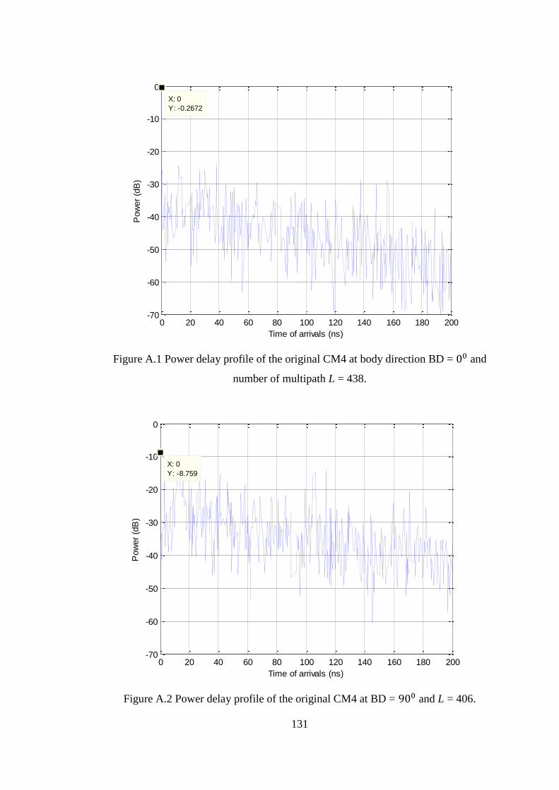
131
Figure A.1 Power delay profile of the original CM4 at body direction BD = 00 and
number of multipath L = 438.
Figure A.2 Power delay profile of the original CM4 at BD = 900 and L = 406.
0 20 40 60 80 100 120 140 160 180 200-70
-60
-50
-40
-30
-20
-10
0
X: 0
Y: -0.2672
Time of arrivals (ns)
Pow
er
(dB
)
0 20 40 60 80 100 120 140 160 180 200-70
-60
-50
-40
-30
-20
-10
0
X: 0
Y: -8.759
Time of arrivals (ns)
Pow
er
(dB
)
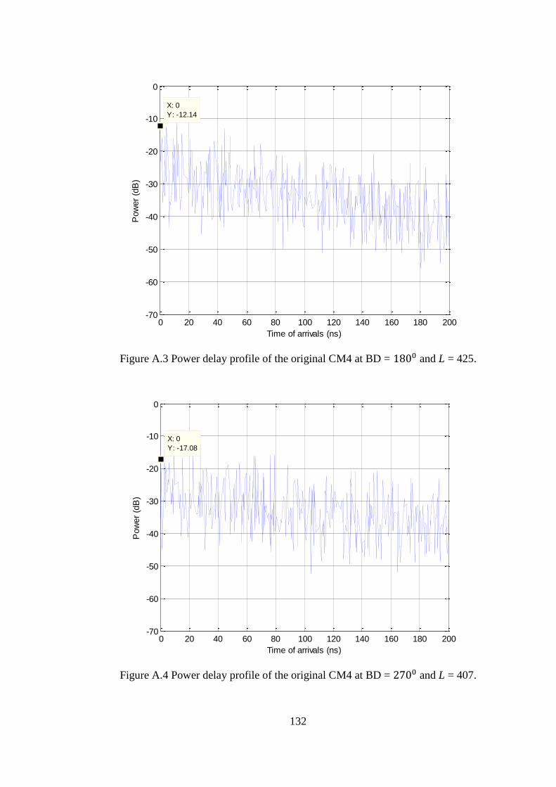
132
Figure A.3 Power delay profile of the original CM4 at BD = 1800 and L = 425.
Figure A.4 Power delay profile of the original CM4 at BD = 2700 and L = 407.
0 20 40 60 80 100 120 140 160 180 200-70
-60
-50
-40
-30
-20
-10
0
Time of arrivals (ns)
Pow
er
(dB
)
X: 0
Y: -12.14
0 20 40 60 80 100 120 140 160 180 200-70
-60
-50
-40
-30
-20
-10
0
X: 0
Y: -17.08
Time of arrivals (ns)
Pow
er
(dB
)
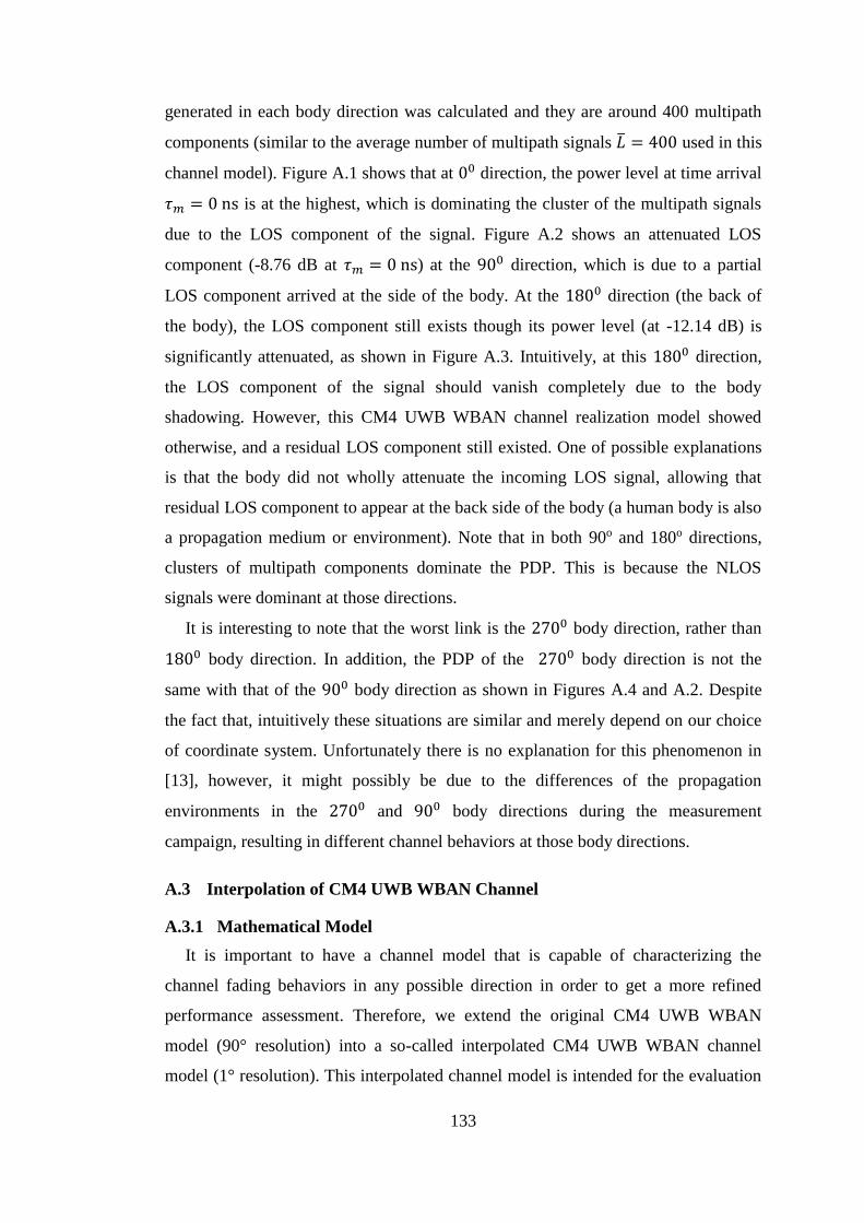
133
generated in each body direction was calculated and they are around 400 multipath
components (similar to the average number of multipath signals �̅� = 400 used in this
channel model). Figure A.1 shows that at 00 direction, the power level at time arrival
𝜏𝑚 = 0 ns is at the highest, which is dominating the cluster of the multipath signals
due to the LOS component of the signal. Figure A.2 shows an attenuated LOS
component (-8.76 dB at 𝜏𝑚 = 0 ns) at the 900 direction, which is due to a partial
LOS component arrived at the side of the body. At the 1800 direction (the back of
the body), the LOS component still exists though its power level (at -12.14 dB) is
significantly attenuated, as shown in Figure A.3. Intuitively, at this 1800 direction,
the LOS component of the signal should vanish completely due to the body
shadowing. However, this CM4 UWB WBAN channel realization model showed
otherwise, and a residual LOS component still existed. One of possible explanations
is that the body did not wholly attenuate the incoming LOS signal, allowing that
residual LOS component to appear at the back side of the body (a human body is also
a propagation medium or environment). Note that in both 90o and 180o directions,
clusters of multipath components dominate the PDP. This is because the NLOS
signals were dominant at those directions.
It is interesting to note that the worst link is the 2700 body direction, rather than
1800 body direction. In addition, the PDP of the 2700 body direction is not the
same with that of the 900 body direction as shown in Figures A.4 and A.2. Despite
the fact that, intuitively these situations are similar and merely depend on our choice
of coordinate system. Unfortunately there is no explanation for this phenomenon in
[13], however, it might possibly be due to the differences of the propagation
environments in the 2700 and 900 body directions during the measurement
campaign, resulting in different channel behaviors at those body directions.
A.3 Interpolation of CM4 UWB WBAN Channel
A.3.1 Mathematical Model
It is important to have a channel model that is capable of characterizing the
channel fading behaviors in any possible direction in order to get a more refined
performance assessment. Therefore, we extend the original CM4 UWB WBAN
model (90° resolution) into a so-called interpolated CM4 UWB WBAN channel
model (1° resolution). This interpolated channel model is intended for the evaluation
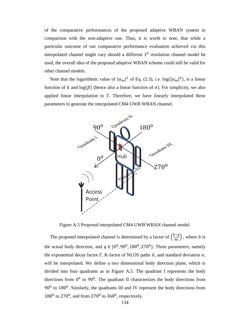
134
of the comparative performances of the proposed adaptive WBAN system in
comparison with the non-adaptive one. Thus, it is worth to note, that while a
particular outcome of our comparative performance evaluation achieved via this
interpolated channel might vary should a different 10 resolution channel model be
used, the overall idea of the proposed adaptive WBAN scheme could still be valid for
other channel models.
Note that the logarithmic value of |𝛼𝑚|2 of Eq. (2.3), i.e. log(|𝛼𝑚|2), is a linear
function of 𝑘 and log(𝛽) (hence also a linear function of 𝜎). For simplicity, we also
applied linear interpolation to Γ. Therefore, we have linearly interpolated these
parameters to generate the interpolated CM4 UWB WBAN channel.
Figure A.5 Proposed interpolated CM4 UWB WBAN channel model.
The proposed interpolated channel is determined by a factor of (𝑏−𝑞
90) , where 𝑏 is
the actual body direction, and 𝑞 ∈ {00, 900, 1800, 2700}. Three parameters, namely
the exponential decay factor Γ, K-factor of NLOS paths 𝑘, and standard deviation 𝜎,
will be interpolated. We define a two dimensional body direction plane, which is
divided into four quadrants as in Figure A.5. The quadrant I represents the body
directions from 00 to 900. The quadrant II characterizes the body directions from
900 to 1800. Similarly, the quadrants III and IV represent the body directions from
1800 to 2700, and from 2700 to 3600, respectively.
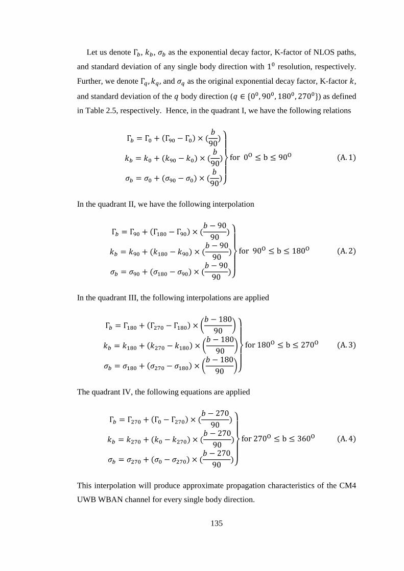
135
Let us denote Γ𝑏, 𝑘𝑏, 𝜎𝑏 as the exponential decay factor, K-factor of NLOS paths,
and standard deviation of any single body direction with 10 resolution, respectively.
Further, we denote Γ𝑞 , 𝑘𝑞 , and 𝜎𝑞 as the original exponential decay factor, K-factor 𝑘,
and standard deviation of the 𝑞 body direction (𝑞 ∈ {00, 900, 1800, 2700}) as defined
in Table 2.5, respectively. Hence, in the quadrant I, we have the following relations
Γ𝑏 = Γ0 + (Γ90 − Γ0) × (𝑏
90)
𝑘𝑏 = 𝑘0 + (𝑘90 − 𝑘0) × (𝑏
90)
𝜎𝑏 = 𝜎0 + (𝜎90 − 𝜎0) × (𝑏
90)}
for 0O ≤ b ≤ 90O (A. 1)
In the quadrant II, we have the following interpolation
Γ𝑏 = Γ90 + (Γ180 − Γ90) × (𝑏 − 90
90)
𝑘𝑏 = 𝑘90 + (𝑘180 − 𝑘90) × (𝑏 − 90
90)
𝜎𝑏 = 𝜎90 + (𝜎180 − 𝜎90) × (𝑏 − 90
90)}
for 90O ≤ b ≤ 180O (A. 2)
In the quadrant III, the following interpolations are applied
Γ𝑏 = Γ180 + (Γ270 − Γ180) × (𝑏 − 180
90)
𝑘𝑏 = 𝑘180 + (𝑘270 − 𝑘180) × (𝑏 − 180
90)
𝜎𝑏 = 𝜎180 + (𝜎270 − 𝜎180) × (𝑏 − 180
90)}
for 180O ≤ b ≤ 270O (A. 3)
The quadrant IV, the following equations are applied
Γ𝑏 = Γ270 + (Γ0 − Γ270) × (𝑏 − 270
90)
𝑘𝑏 = 𝑘270 + (𝑘0 − 𝑘270) × (𝑏 − 270
90)
𝜎𝑏 = 𝜎270 + (𝜎0 − 𝜎270) × (𝑏 − 270
90)}
for 270O ≤ b ≤ 360O (A. 4)
This interpolation will produce approximate propagation characteristics of the CM4
UWB WBAN channel for every single body direction.
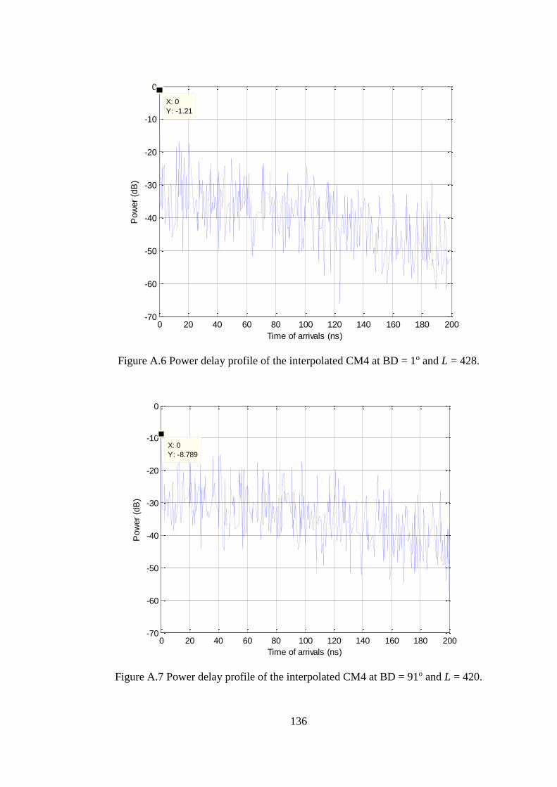
136
Figure A.6 Power delay profile of the interpolated CM4 at BD = 1o and L = 428.
Figure A.7 Power delay profile of the interpolated CM4 at BD = 91o and L = 420.
0 20 40 60 80 100 120 140 160 180 200-70
-60
-50
-40
-30
-20
-10
0
X: 0
Y: -1.21
Time of arrivals (ns)
Pow
er
(dB
)
0 20 40 60 80 100 120 140 160 180 200-70
-60
-50
-40
-30
-20
-10
0
X: 0
Y: -8.789
Time of arrivals (ns)
Pow
er
(dB
)
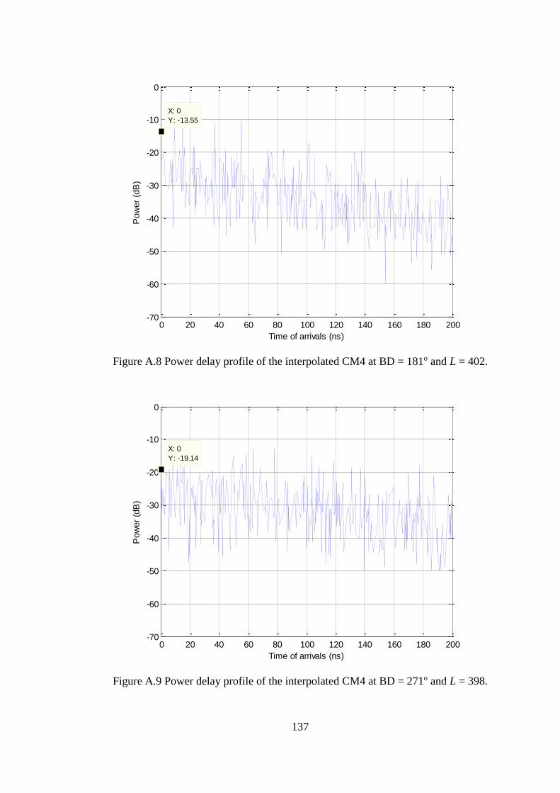
137
Figure A.8 Power delay profile of the interpolated CM4 at BD = 181o and L = 402.
Figure A.9 Power delay profile of the interpolated CM4 at BD = 271o and L = 398.
0 20 40 60 80 100 120 140 160 180 200-70
-60
-50
-40
-30
-20
-10
0
X: 0
Y: -13.55
Time of arrivals (ns)
Pow
er
(dB
)
0 20 40 60 80 100 120 140 160 180 200-70
-60
-50
-40
-30
-20
-10
0
X: 0
Y: -19.14
Time of arrivals (ns)
Pow
er
(dB
)

138
The PDP characteristics of this interpolated CM4 UWB WBAN channel were
generated by a MATLAB programming code (cf. Appendix A) and are described in
Figures A.6 to A.9. We intentionally show the PDP of the corresponding body
directions of the original CM4 UWB WBAN channel as presented in Figures A.1 to
A.4, plus 10 (Figures A.6 to A.9). This was done so, to show that the interpolated
CM4 UWB WBAN channel was able to produce 10 resolution channel, in addition to
the assumption that shifting 10 angle of direction would not change the channel
characteristic significantly. The Figures A.6 to A.9 resemble the PDP characteristics
of the original CM4 UWB WBAN channel (cf. Figures A.1 to A.4) mentioned above,
with minor variations. These facts gave us a basis to infer that the interpolated CM4
UWB WBAN channel model is a good extension of the original CM4 UWB WBAN
channel model. In addition, to give examples that this interpolated CM4 UWB
WBAN channel model work for any random body directions, Figures A.10 to A.13
show PDP characteristics for 450, 1350, 2250 and 3150 body directions,
respectively.
Figure A.10 Power delay profile of the interpolated CM4 at BD = 45o.
0 20 40 60 80 100 120 140 160 180 200-70
-60
-50
-40
-30
-20
-10
0
Time of arrivals (ns)
Pow
er
(dB
)
X: 0
Y: -5.555
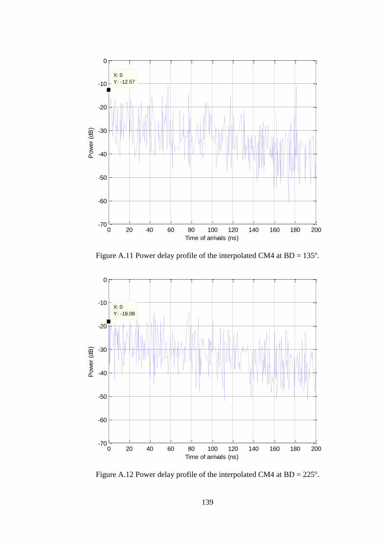
139
Figure A.11 Power delay profile of the interpolated CM4 at BD = 135o.
Figure A.12 Power delay profile of the interpolated CM4 at BD = 225o.
0 20 40 60 80 100 120 140 160 180 200-70
-60
-50
-40
-30
-20
-10
0
Time of arrivals (ns)
Pow
er
(dB
)
X: 0
Y: -12.57
0 20 40 60 80 100 120 140 160 180 200-70
-60
-50
-40
-30
-20
-10
0
X: 0
Y: -18.08
Time of arrivals (ns)
Pow
er
(dB
)
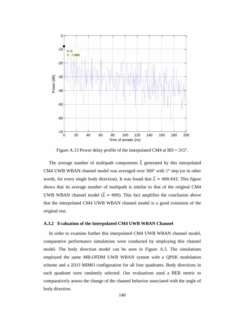
140
Figure A.13 Power delay profile of the interpolated CM4 at BD = 315o.
The average number of multipath components �̅� generated by this interpolated
CM4 UWB WBAN channel model was averaged over 360° with 1° step (or in other
words, for every single body direction). It was found that �̅� = 400.443. This figure
shows that its average number of multipath is similar to that of the original CM4
UWB WBAN channel model (�̅� = 400). This fact amplifies the conclusion above
that the interpolated CM4 UWB WBAN channel model is a good extension of the
original one.
A.3.2 Evaluation of the Interpolated CM4 UWB WBAN Channel
In order to examine further this interpolated CM4 UWB WBAN channel model,
comparative performance simulations were conducted by employing this channel
model. The body direction model can be seen in Figure A.5. The simulations
employed the same MB-OFDM UWB WBAN system with a QPSK modulation
scheme and a 2I1O MIMO configuration for all four quadrants. Body directions in
each quadrant were randomly selected. Our evaluations used a BER metric to
comparatively assess the change of the channel behavior associated with the angle of
body direction.
0 20 40 60 80 100 120 140 160 180 200-70
-60
-50
-40
-30
-20
-10
0
X: 0
Y: -7.899
Time of arrivals (ns)
Pow
er
(dB
)
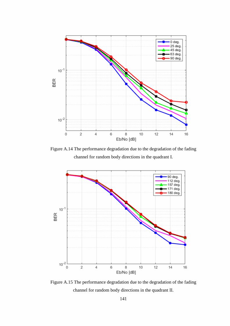
141
Figure A.14 The performance degradation due to the degradation of the fading
channel for random body directions in the quadrant I.
Figure A.15 The performance degradation due to the degradation of the fading
channel for random body directions in the quadrant II.
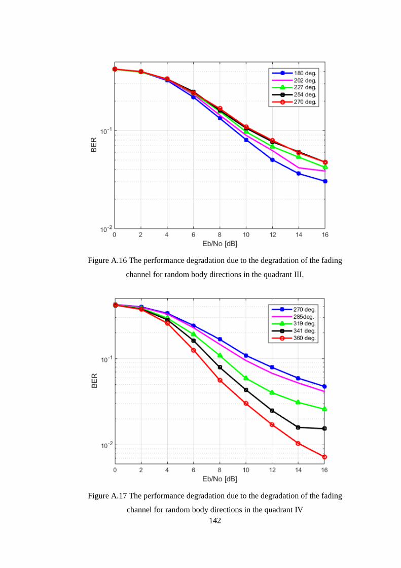
142
Figure A.16 The performance degradation due to the degradation of the fading
channel for random body directions in the quadrant III.
Figure A.17 The performance degradation due to the degradation of the fading
channel for random body directions in the quadrant IV
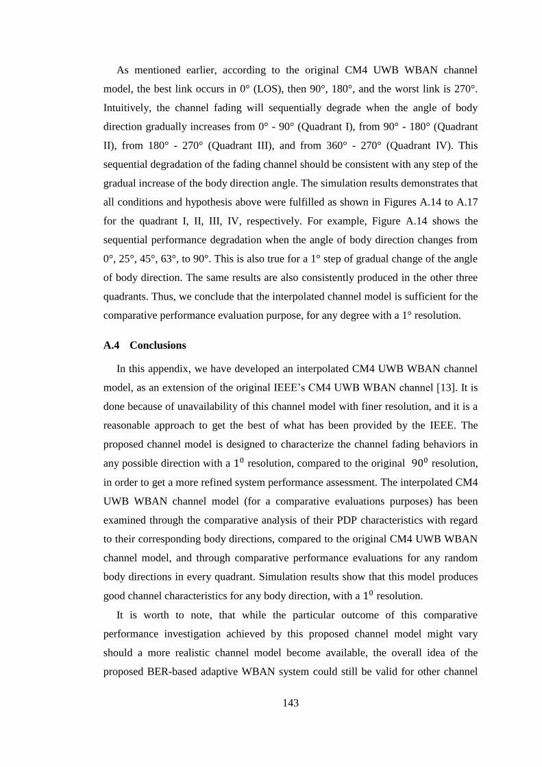
143
As mentioned earlier, according to the original CM4 UWB WBAN channel
model, the best link occurs in 0° (LOS), then 90°, 180°, and the worst link is 270°.
Intuitively, the channel fading will sequentially degrade when the angle of body
direction gradually increases from 0° - 90° (Quadrant I), from 90° - 180° (Quadrant
II), from 180° - 270° (Quadrant III), and from 360° - 270° (Quadrant IV). This
sequential degradation of the fading channel should be consistent with any step of the
gradual increase of the body direction angle. The simulation results demonstrates that
all conditions and hypothesis above were fulfilled as shown in Figures A.14 to A.17
for the quadrant I, II, III, IV, respectively. For example, Figure A.14 shows the
sequential performance degradation when the angle of body direction changes from
0°, 25°, 45°, 63°, to 90°. This is also true for a 1° step of gradual change of the angle
of body direction. The same results are also consistently produced in the other three
quadrants. Thus, we conclude that the interpolated channel model is sufficient for the
comparative performance evaluation purpose, for any degree with a 1° resolution.
A.4 Conclusions
In this appendix, we have developed an interpolated CM4 UWB WBAN channel
model, as an extension of the original IEEE’s CM4 UWB WBAN channel [13]. It is
done because of unavailability of this channel model with finer resolution, and it is a
reasonable approach to get the best of what has been provided by the IEEE. The
proposed channel model is designed to characterize the channel fading behaviors in
any possible direction with a 10 resolution, compared to the original 900 resolution,
in order to get a more refined system performance assessment. The interpolated CM4
UWB WBAN channel model (for a comparative evaluations purposes) has been
examined through the comparative analysis of their PDP characteristics with regard
to their corresponding body directions, compared to the original CM4 UWB WBAN
channel model, and through comparative performance evaluations for any random
body directions in every quadrant. Simulation results show that this model produces
good channel characteristics for any body direction, with a 10 resolution.
It is worth to note, that while the particular outcome of this comparative
performance investigation achieved by this proposed channel model might vary
should a more realistic channel model become available, the overall idea of the
proposed BER-based adaptive WBAN system could still be valid for other channel

144
models. In addition, we can tune the adaptive schemes using a more realistic channel
model when it becomes available.

145
APPENDIX B
MATLAB Code for Interpolated CM4 UWB WBAN Channel Realization
function [h, t, n_p] = uwb_hospban_chan_CM4_interp_1(num_channels,
bd) % Function for getting channel realizations for UWB Hospital BAN
channelCM4, By Igor Dotlic ([email protected]) March 2009. %MODIFIED BY MIFTADI SUDJAI, DEC 2012, for LINEAR INTERPOLATION %of ANY BODY DIRECTION % Input variables: % num_channels - number of channel realizations % bd - body_direction in degree, rounded up to the nearest
integer. % Output variables: % h - comlex multipath amplitude responses % t - times of multipath arrivals (ns) % n_p - number of paths for each channel realization % Fixed model parameters L_mean = 400; % mean number of arrival paths lambda_inv= 0.50125; % mean time between arrivals (ns) % Model parameters that depend on body direction %bd1 Gamma_0 = 44.6346;% (ns) Gamma_360=Gamma_0; k_abs_0 = 5.111739; k_abs_360=k_abs_0; sigma_0 = 7.30; sigma_360 =sigma_0 ; %bd2 Gamma_90 = 54.2868; % (ns) k_abs_90 = 4.348859975; sigma_90 = 7.08; %bd3 Gamma_180 = 53.4186; % (ns) k_abs_180 = 3.638084447; sigma_180 = 7.03; %bd4 Gamma_270 = 83.9635; % (ns) k_abs_270 = 3.983472211; sigma_270 = 7.19;
%% LINEAR INTERPOLATION for ANY BODY DIRECTION %Interpolation is done to obtain 1 deg. resolution. %The input of body direction should be rounded up to the nearest
integer!
if bd>=0 && bd<=90 Gamma = Gamma_0 + (Gamma_90 - Gamma_0)*(bd/90); % (ns) k_abs = k_abs_0 + (k_abs_90 - k_abs_0)*(bd/90); sigma = sigma_0 + (sigma_90 - sigma_0)*(bd/90); elseif bd>=91 && bd<=180 Gamma = Gamma_90 + (Gamma_180 - Gamma_90)*((bd-90)/90); % (ns) k_abs = k_abs_90 + (k_abs_180 - k_abs_90)*((bd-90)/90); sigma = sigma_90 + (sigma_180 - sigma_90)*((bd-90)/90); elseif bd>=181 && bd<=270 Gamma = Gamma_180 + (Gamma_270 - Gamma_180)*((bd-180)/90); % (ns)

146
k_abs = k_abs_180 + (k_abs_270 - k_abs_180)*((bd-180)/90); sigma = sigma_180 + (sigma_270 - sigma_180)*((bd-180)/90); elseif bd>=271 && bd<=360 Gamma = Gamma_270 + (Gamma_0 - Gamma_270)*((bd-270)/90); % (ns) k_abs = k_abs_270 + (k_abs_0 - k_abs_270)*((bd-270)/90); sigma = sigma_270 + (sigma_0 - sigma_270)*((bd-270)/90); end %% % Calculating number of paths n_p = poissrnd(L_mean, 1, num_channels); for k_chan = 1:num_channels n_p(k_chan) = max(n_p(k_chan), 1); end % Maximum number of paths n_p_max = max(n_p); % Allocating memory for channel realizations h = zeros(n_p_max, num_channels); t = zeros(n_p_max, num_channels); % Calculating path arrival times t_dif = exprnd(lambda_inv, num_channels, n_p_max-1); for k_chan = 1:num_channels t(2:n_p(k_chan),k_chan) = cumsum(t_dif(k_chan, 1:n_p(k_chan)-1)); end % Calculating path levels for k_chan = 1:num_channels h(1,k_chan) = exp(i*rand*2*pi)*sqrt(10^(sigma*randn/10)); % Paths 2 onwards for k_p = 2:n_p(k_chan) h(k_p, k_chan) = exp(i*rand*2*pi)*... sqrt(exp(-t(k_p,k_chan)/Gamma-k_abs)*10^(sigma*randn/10)); end % Normalizing current PDP realization (may be commented out) h(:,k_chan) = h(:,k_chan)/norm(h(:,k_chan)); end

147
APPENDIX C
Proof that A is a Totally Unimodullar Matrix and its ease of
use in Linear Programming
Let we start by briefly summarizing the definition and some important properties
of the Totally Unimodular (TUM) matrix used in Section 5.4 of Chapter 5.
Definition:
A matrix G is totally unimodular if the determinant of every square of submatrix
G has value -1, 0, or 1 [114], [115]. Thus,
𝐆 is TUM ⟺ ∀ square submatrix 𝐆, det(𝐆) ∈ {−1,0,1} (C. 1)
Proposition 1 [114], [115]: Some properties of the TUM are outline below.
If matrix G is TUM, then
1. Components of G are either: -1, 0, or 1.
Proof: 𝑔𝑖,𝑗 is a component of G and also a submatrix of G, so det(𝑔𝑖,𝑗) =
𝑔𝑖,𝑗 ∈ {−1,0,1}.
2. 𝐆𝑇 is also a TUM
Proof: The determinant of a transpose matrix G is not changed, compared to
the determinant of G. Thus, If matrix G is TUM, so do the transpose matrix
𝐆𝑇.
3. If 𝐆′ is a submatrix of G, then 𝐆′ is also a TUM
Proof: all submatrix of G has determinant of -1, 0, or 1 as defined above, so
𝐆′ is also TUM.
Recall from Eqs. (5.16) and (5.17) that matrix 𝐀 = 𝐈𝑄⨂𝟏9𝑇 ∈ {0,1}𝑄×9𝑄, where 𝐈𝑄
is a 𝑄 × 𝑄 identity matrix , ⨂ denotes the Kronecker product and 𝟏9 is an all one
9 × 1 vector. It is obvious that every element of A has value 0 or 1. It also can be
seen that every determinant of square submatrix of A, det(𝐀′) ∈ {−1,0,1}. Thus,
matrix A is a Totally unimodular matrix.
Totally unimodular matrix is popular in the Linear Programming (LP) applica-
tions for the following property [113], [114], [115].

148
Proposition 2: If max 𝒄𝑇𝒙:𝐆𝒙 ≤ 𝐛 is a linear program, where 𝐆 is TUM, and 𝒃 is
integer, then all vertex solutions of the LP is integer. Proof is given as follow [114],
[115].
Denote 𝐯 to be a vertex solution of the LP. The submatrix 𝐆′ is a full rank square
matrix, and 𝐛′ is a submatrix of 𝐛, in which 𝐆′𝐯 = 𝐛′. Thus, 𝐯 = (𝐆′)−𝟏𝐛′. By
Cramer’s rule, 𝑣𝑖 = det (𝐆′𝑖) det (𝐆′)⁄ . 𝐆′
𝑖 is matrix 𝐆′ where the 𝑖-th column is
replaced by 𝐛′. Given the properties of matrix 𝐆 and 𝐆′as mentioned above, the 𝑖-
th component of 𝐯 is provided by
𝑣𝑖 = det(𝐆′
𝑖)
det(𝐆′)=
(𝑏1 det(𝐆′1) − 𝑏2 det(𝐆′
2) + ⋯ )
det(𝐆′) (C. 2)
Since 𝒃 is integer and 𝐆′ is a full rank TUM, thus 𝑣𝑖 is integer.
149
BIBLIOGRAPHY
[1] M. Chen, et.al, “Body area networks: A survey”, Springer J. Mob. Netw. App.,
vol. 16, no. 2, pp.171–193, Aug. 2010.
[2] S. Ullah, et.al, “A comprehensive survey of wireless body area networks on
PHY, MAC, and Network Layers solutions”, Springer J. Med. Sys., vol. 36, no.
3, pp. 1065-1094, Aug. 2010.
[3] B. Latre´, et.al, “A survey on wireless body area networks”, Springer J.
Wireless Netw., vol. 17, no. 1, pp. 1–18, Nov. 2010.
[4] R. Cavallari, et.al, “A survey on wireless body area networks: Technologies
and design challenges”, IEEE Commun. Surv. Tutor., vol. 99, no. 3, pp. 1635-
1657, Feb. 2014.
[5] H. Cao, et.al, “Enabling technologies for Wireless Body Area Networks: A
survey and outlook”, IEEE Commun. Mag., vol. 47, no.12, pp. 84-93, Dec.
2009.
[6] R. Marin-Perianu, et.al, “A performance analysis of a wireless body area
network monitoring system for professional cycling”, Springer J. Personal
Ubiquit. Comput., vol. 17, no.1, pp. 197-209, Nov. 2011.
[7] K. M. Thotahewa, J. Redoute´ and M. R. Yuce, Ultra-Wideband Wireless Body
Area Networks, Springer, Switzerland, 2014.
[8] “Federal communications commission (FCC), code of federal regulations
(CFR), title 47 part 95, MCIS band plan”, Available Online: www.fcc.gov,
Nov. 2015.
[9] “Federal communications commission (FCC), code of federal regulations
(CFR), title 47 part 95, WMTS band plan”, Available Online: www.fcc.gov,
Nov. 2015.
[10] M. Hämäläinen, et.al, “Performance comparison of the different IR-UWB
receivers in wireless body area networks”, Proc. IEEE Int. Conf. Ultra-
Wideband, pp. 230-234, Sep. 2011.
[11] R. C. Santiago, I. Balasingham and J. Bergsland, “Ultra-wideband technology
in medicine: A survey”, J. Elec. and Com. Eng., vol. 2012, pp. 1-9, Jan. 2012.
[12] M. Hernandez and R. Kohno, “UWB systems for body area networks in IEEE
802.15.6”, Proc. IEEE Int. Conf. Ultra-Wideband, pp. 235-239, Sep. 2011.
150
[13] K. Y. Yazdandoost and K. Sayrafian-Pour, “Channel model for Body Area
Network (BAN) “, IEEE P802.15-08-0780-12-0006, Nov. 2010.
[14] D. Miniutti, et.al, “Narrowband on body to off body channel characterization
for BAN,” IEEE 802.15-08-0559-00-0006, Aug. 2008.
[15] N. G. Kang, et.al, “Channel model for WBANs,” IEEE 802.15-08-0781-00-
0006, Nov. 2008.
[16] H. Sawada, et.al, “Channel model between body surface and wireless access
point for UWB band,” IEEE 802.15-08-0576-00-0006, Aug. 2008.
[17] R. Kohno, et.al, “R&D and standardization of Body Area Network (BAN) for
medical healthcare”, Proc. IEEE Int. Conf. Ultra-Wideband, vol. 3, pp. 5-8,
Sep. 2008.
[18] A. Astrin, H. B. Li and R. Kohno, “Standardization for body area networks”,
IEICE Trans. Commun., vol. E.92-B, no.2, p. 366-372, Feb. 2009.
[19] K. Kwak, S. Ullah, and N. Ullah, “An overview of IEEE 802.15.6 standard”,
Proc. Int. Symp. Applied Sciences Biomed. Commun. Tech., pp. 1-6, Nov. 2010.
[20] IEEE 802.15Task Group 6 (TG6) Body Area Networks, Available Online:
http://www.ieee802.org/15/pub/TG6.html, Nov. 2015.
[21] IEEE Computer Society, “IEEE standard for local and metropolitan area
networks-Part 15.6: Wireless Body Area Networks”, Feb. 2012.
[22] R. Aiello and A. Batra, Ultra-Wideband Systems: Technologies and
Applications, Newness, Burlington, 2006.
[23] W. P. Siriwongpairat, et.al, “Multiband-OFDM MIMO coding framework for
UWB communication systems”, IEEE Trans. Signal Processing, vol. 54, no. 1,
pp. 214-224, Jan. 2006.
[24] W. P. Siriwongpairat and K. J. R. Liu, Ultra-Wideband Communication
Systems: Multi Band OFDM Approach, John Wiley and Sons, New Jersey,
2008.
[25] Q. H. Abbasi, et.al, “Radio channel characterization and OFDM-based ultra-
wideband system modelling for body-centric wireless networks”, Proc. Int.
Conf. Body Sensor Netw., pp. 89-94, Jul. 2011.
[26] Q. H. Abbasi, et.al, “Diversity antenna techniques for enhanced ultra-
wideband body-centric communications”, Proc. IEEE Int. Symp. Anten.
Propag., pp. 1323-1326, Jul. 2011.
151
[27] Y. Chen, et.al, “Cooperative communications in ultra-wideband wireless body
area networks: Channel modelling and system diversity analysis”, IEEE J.
Selec. Areas Commun., vol. 27, no. 1, pp. 5-16 , Jan. 2009.
[28] L. Liu, et.al, “Investigation of channel spatial diversity for dual-link
cooperative communications in WBAN”, Proc. European Conf. Antenn.
Propag., pp. 2972-2976, Apr. 2011.
[29] A. Batra, et.al, “Multiband OFDM physical layer specification,” WiMedia
Alliance, Final Deliverable 1.5, Aug. 2009.
[30] L. C. Tran and A. Mertins, “Space-time-frequency code implementation in
MB-OFDM UWB communications: Design criteria and performance”, IEEE
Trans. Wireless Commun., vol. 8, no. 2, pp. 701-713, Feb. 2009.
[31] P. S. Hall, Y. Hao and K. Ito, “Guest editorial for the special issue on antennas
and propagation on body-centric wireless communications,” IEEE Trans.
Anten. Propag., vol. 57, no. 4, pp. 834–836, Apr. 2009.
[32] A. Taparugssanagorn, et.al, “A review of channel modelling for wireless body
area network in wireless medical communications”, Proc. Int. Symp. Wireless
Personal Multimedia Commun., pp. 1-5, Sep. 2008.
[33] J. Takada, et.al, “Static propagation and channel models in body area”, COST
2100 TD(08)639, Oct. 2008.
[34] Y. Wang, et.al, “Characterization of the indoor multi-antenna body-to-body
radio channel”, IEEE Trans. Anten. Propag., vol. 57, no. 4, pp. 972-979, Apr.
2009.
[35] Q. H. Abbasi, et.al, “Characterization and modelling of ultra-wideband radio
links for optimum performance of body area network in health care
applications” Proc. IEEE Int. Workshop Anten. Tech., pp. 206-209, Mar. 2011.
[36] Q. H. Abbasi, et.al, “Experimental characterization and statistical analysis of
the pseudo-dynamic ultra-wideband on-body radio channel”, IEEE Anten.
Wireless Propag. Letters, pp. 748-751, vol. 10, Jul. 2011.
[37] M. M. Khan, et.al, “Investigation of body shape variations effect on the ultra-
wideband on-body radio propagation channel”, Proc. Int. Conf. Electromagnet.
Advance App., pp. 1128-113, Sep. 2011.
152
[38] H. Viittala, et.al, “Different experimental WBAN channel models and
IEEE802.15.6 models: comparison and effects”, Proc. Int. Symp. App. Science
Biomed. Commun. Tech., pp. 1-5, Nov. 2009.
[39] Q. Wang, et.al, “An on-body channel model for UWB body area
communications for various postures”, IEEE Trans. Anten. propag., vol. 57, no.
4, pp. 991-998, Apr. 2009.
[40] K. Takizawa, T. Aoyagi and R. Kohno, “Channel modelling and performance
evaluation of UWB-based wireless body area networks”, Int. J. Wideband
Commun. System, vol.2, no. 3, pp. 125-133, Dec. 2012.
[41] T. Aoyagi, et.al, “Development of a WBAN channel model for capsule
endoscopy”, Proc. IEEE Anten. Propag. Society Int. Symp., pp. 1-4, Jun. 2009.
[42] X. D. Yang, et.al, ”Spatial correlation analysis of on-body radio channels
considering statistical significance”, IEEE Anten. Wireless Propag. Letters, vol.
10, pp. 780-783, Aug. 2011.
[43] L. Theogarajan, et.al, “Minimally invasive retinal prosthesis”, Proc. IEEE Int.
Conf. Solid State Circuits, pp. 99–108, Feb. 2006.
[44] S. Arnon, et.al, “A comparative study of wireless communication network
configurations for medical applications”, IEEE J. Wireless Commun., vol. 10,
no. 1, pp. 56–61, Feb. 2003.
[45] C. A. Chin, et.al, “Advanced challenges of wireless body area networks for
healthcare applications”, IEEE Workshop Comp. Netw. Commun., pp. 99-103,
Aug. 2012.
[46] FCC, Revision of part 15 of the commission’s rules regarding ultra-wideband
transmission systems, FCC docket 02-48, Apr. 22, 2002.
[47] M. G. Di Benedetto and G. Giancola, Understanding Ultra-Wideband Radio
Fundamentals, Prentice Hall PTR, New Jersey, 2004.
[48] Y. F. Chen, et.al, “A current-mode RF transmitter for 6–9 GHz MB-OFDM
UWB application”, Science China Inf. Science, vol. 54, no.2, pp. 419–428, Feb.
2011.
[49] J. Ding, et.al, “Energy-efficient cooperative relay selection for UWB based
body area networks”, Proc. IEEE Int. Conf. UWB, pp. 97-102, Sep. 2013.
153
[50] X. Huang, H. Shan and X. Shen, “On energy efficiency of cooperative
communications in wireless body area networks”, Proc. IEEE Wireless
Commun. Netw. Conf., pp. 1097-1101, Mar. 2011.
[51] A. J. Paulraj, et.al, “An overview of MIMO communications- A key to gigabit
wireless”, Proc. IEEE, vol.92, no. 2, pp. 198-218, Feb. 2004
[52] D. Gesbert, et.al, “From theory to practice: An overview of MIMO space-time
coded wireless systems,” IEEE J. Select. Areas Commun., vol. 21, no. 3, pp.
281-302, Apr. 2003.
[53] A. F. Naguib and A. R. Calderbank, “Space-time coding and signal processing
for high data rate wireless communications,” Wireless Commun. Mob. Comput.,
vol. 1, pp. 13-43, Jan. 2001.
[54] V. Tarokh, N. Seshadri and A. R. Calderbank, “Space-time codes for high data
rate wireless communication: Performance analysis and code construction,”
IEEE Trans. Inf. Theory, vol. 44, no. 2, pp. 744-765, Mar. 1998.
[55] S. M. Alamouti, “A simple transmit diversity technique for wireless
communications,” IEEE J. Selec. Areas Commun., vol. 16, no. 8, pp. 1451-
1458, Oct. 1998.
[56] A. J. Paulraj, R. Nabar and D. Gore, Introduction to Space-Time Wireless
Communications, Cambridge, Cambridge University Press, 2003.
[57] H. Bocskei and A.J. Paulraj, Multiple-input multiple-output (MIMO) Wireless
Systems, Cambridge, Cambridge University Press, 2003.
[58] S. Sezginer and H. Sari, “A high-rate full-diversity 2x2 space-time code with
simple maximum likelihood decoding”, Proc. IEEE Int. Symp. Sign. Process.
Inf. Tech., pp. 1132-1136, Dec. 2007.
[59] P. W. Wolniansky, et.al, “V-BLAST: An architecture for realizing very high
data rates over the rich scattering wireless channel,” Proc. Int. Symp. Sign. Syst.
Electronics, pp. 259-300, Apr. 1998.
[60] H. Huang, H. Viswanathan and G .J. Foschini, “Achieve high data rates in
CDMA systems using BLAST techniques,” Proc. Global Telecommun. Conf.,
vol. 5, pp. 2316-2320, Dec. 1999.
[61] TIA/EIA IS-2000 Physical layer specification of CDMA spread spectrum
communication system, Jun. 2000.
154
[62] IST METRA, “The IST METRA Project”, Available Online:
http://www.researchgate.net/publication/3196747_The_IST_METRA_project,
Nov. 2015.
[63] High speed downlink packet access (HSDPA), 3GPP TR 25.855, V5.0.0
(Release 5), Sep. 2001.
[64] Airgo Networks, et.al, “WWiSE IEEE 802.11n proposal technical summary”,
WWiSE group, Aug. 2004.
[65] F. Petré, et.al, “MIMO-OFDM for high-speed WLANs,” IMEC, Jan. 2004.
[66] Intel Corp., “WiMAX,” Intel Tech. Journ., vol. 8, no. 3, pp. 173-258, Aug.
2004.
[67] G. J. Foschini, “Layered space-time architecture for wireless communication in
a fading environment when using multiple antennas,” Bell Labs Syst. Tech. J.,
vol. 1, pp. 41-59, autumn 1996.
[68] E. Biglieri, et.al, MIMO wireless communications, Cambridge University Press,
Cambridge, 2007.
[69] N. Costa and S. Haykin, Multiple input multiple output channel model: theory
and practice, John Wiley & Son, New Jersey, 2010.
[70] V. Tarokh, H. Jafarkhani and A. R. Calderbank, “Spacetime block coding for
wireless communications: Performance results”, IEEE J. Selec. Areas
Commun., vol. 17, no. 3, pp.451-460, Mar. 1999.
[71] V. Tarokh, et.al, “Combined array processing and space time coding”, IEEE
Trans. Inf. Theory, vol. 45, no.4, pp.1121-1128, May 1999.
[72] V. Tarokh, H. Jafarkhani and A. R. Calderband, “Space-time block codes from
orthogonal designs,” IEEE Trans. Info. Theory, vol. 45, no. 5, pp. 1456-1467,
Jul. 1999.
[73] G. J. Foschini and M. J. Gans, “On limits of wireless communications in a
fading environment using multiple antennas,” Wireless Personal Commun., vol.
6, no. 3, pp. 311-355, Mar. 1998.
[74] J. Proakis, Digital Communications, 4th Edition, McGraw Hill, New York,
2000.
[75] I. E. Telatar, “Capacity of multi-antenna Gaussian channel”, European Trans.
Telecommun., vol. 10, no.6, pp. 585-595, Nov. 1999.
155
[76] A. Czylwik, “Adaptive OFDM for wideband radio channel”, Proc. Global
Telecommun. Conf., vol. 1, pp. 713-718, Nov. 1996.
[77] T. Keller and L. Hanzo, “Adaptive modulation techniques for duplex OFDM
transmission”, IEEE Trans. Vehic. Tech., vol. 49, no. 5, Sep. 2000.
[78] T. Keller and L. Hanzo, “Adaptive multicarrier modulation: a convenient
framework for Time-Frequency processing in wireless communication”, Proc.
IEEE, vol. 88, no.5, May 2000.
[79] S. T. Chung and A. J. Goldsmith, “Degrees of freedom in adaptive modulation:
a unified view”, IEEE Trans. Commun., vol. 49, no. 9, pp. 1561- 1571, Sep.
2001.
[80] S. Fu, et.al, “An enhanced link adaptation for the MB-OFDM UWB system”,
Proc. IEEE Wireless Commun. Netw. Conf., pp. 2070-2075, Apr. 2012.
[81] W. B. Yang and K. Sayrafian-Pour, “Interference mitigation using adaptive
scheme in body area networks”, Int J. Wireless Inf. Netw., vol. 19, pp. 193-200,
Aug. 2012.
[82] J. M. Torrance and L. Hanzo, “Optimization of switching levels for adaptive
modulation in slow rayleigh fading”, IEE Electronics Letters, vol. 32, no.13,
pp. 1167-1169, Jun. 1996.
[83] M. Shafi, S. Ogose and T. Hattori, Wireless Communication in the 21st
Century, IEEE Press, New Jersey, 2002.
[84] L. Hanzo, C. H. Wong and M. S. Yee, Adaptive Wireless Transceivers: Turbo-
Coded, Turbo-Equalised and Space-Time Coded TDMA, CDMA and OFDM
Systems, Wiley-IEEE Press, Chichester, 2002
[85] A. J. Goldsmith and S. Chua, “Variable-rate variable-power MQAM for fading
channels,” IEEE Trans. Commun., vol. 45, pp. 1218–1230, Oct.1997.
[86] J. Garzas, C. B. Calzon and A. G. Armada, “An energy-efficient adaptive
modulation suitable for wireless sensor networks with SER and throughput
constraints”, EURASIP J. Wireless Commun. Netw., vol. 2007, pp. 1-7, Apr.
2007.
[87] S. Cui, A.J. Goldsmith and A. Bahai, “Energy-efficiency of MIMO and
cooperative MIMO techniques in sensor networks”, IEEE J. Selec. Areas
Commun., vol. 22, no. 6, pp. 1089-1098, Aug. 2004.
156
[88] T. Wang and L. Vandendorpe, “On the optimum energy efficiency for flat-
fading channels with rate-dependent circuit power”, IEEE Trans. Commun.,
vol. 61, no.12, pp. 4910-4921, Nov. 2013.
[89] S. Cui, A. J. Goldsmith and A. Bahai, “Energy-constrained modulation
optimization”, IEEE Trans. Wireless Commun., vol.4, no.5, pp. 2349-2360,
Sep. 2005.
[90] O. Amin, et.al, “Energy efficiency and spectral efficiency trade-off for OFDM
systems with imperfect channel estimation”, Proc. IEEE Int. Conf. Commun.,
pp. 3559-3564, Jun. 2014.
[91] N. P. Le, L. C. Tran and F. Safaei, “Energy-efficiency analysis of per-
subcarrier antenna selection with peak-power reduction in MIMO-OFDM
wireless systems”, Int. J. Anten. Propag., vol. 2014, pp. 1-13, Jun. 2014.
[92] J. Abouei, et.al,, “Energy efficiency and reliability in wireless biomedical
implant systems”, IEEE Trans. Inf. Tech. Biomedicine, vol. 15, no.3, pp. 456-
466, May 2011.
[93] H. Wang, et.al, “Information-based energy efficient sensor selection in wireless
body area networks”, Proc. IEEE Int. Conf. Commun., pp. 1-6, Jun. 2011.
[94] G. Fang and E. Dutkiewicz, “BodyMAC: energy efficient TDMA-based MAC
protocol for wireless body area networks”, Proc. IEEE Int. Symp. Commun. Inf.
Tech., pp. 1455-1459, Sep. 2009.
[95] S. J. Marinkovic, et.al, “Energy-efficiency low duty cycle MAC protocol for
wireless body area networks”, IEEE Trans. Inf. Tech. Biomedicine, vol. 13,
no.6, pp. 915-925, Nov. 2009.
[96] J. Elias, “Optimal design of energy-efficient and cost-effective wireless body
area networks”, Elsevier J. Ad Hoc Netw., vol. 13, part B, pp. 560-574, Feb.
2014.
[97] L. C. Tran, et.al, “Space time frequency code in MB-OFDM UWB
communica-tions: Advanced order-8 STFC and its performance”, Proc. Int.
Symp. Commun. Inf. Tech., pp. 380-385, Oct. 2007.
[98] L. C. Tran, et.al, “Unitary differential space-time-frequency codes for MB-
OFDM UWB,” Proc. Of IEEE Int. Symp. Commun. Inf. Tech., pp. 1161-1166,
Sep. 2009.
157
[99] L. C. Tran, A. Mertins and T. A. Wysocki, “Quasi-orthogonal space-time-
frequency codes in MB-OFDM UWB”, J. Comp. Elect. Eng., vol. 36, no. 4, pp.
766–774, Jul. 2010.
[100] L. C. Tran, et.al, “Novel constructions of improved square complex orthogonal
designs for eight transmit antennas,” IEEE Trans. Inf. Theory, vol. 55, no. 10,
pp. 4439-4448, Oct. 2009.
[101] A. F. Molisch, M. Z. Win and J. H. Winters, “Space-time-frequency (STF)
coding for MIMO-OFDM systems,” IEEE Commun. Letter, vol. 6, no. 9, pp.
370–372, Sep. 2002.
[102] M. Fozunbal, S.W. McLaughlin and R.W. Schafer, “On space-time frequency
coding over MIMO-OFDM systems,” IEEE Trans. Wireless Commun., vol. 4,
no. 1, pp. 320–331, Jan. 2005.
[103] T. H. Tan and K. C. Lin,” Performance of space-time block coded MB-OFDM
UWB systems”, Proc. IEEE Annual Commun. Netw. Serv. Research Conf., pp.
323-327, May 2006.
[104] Q. Yang, and K. S. Kwak, “Outage performance of STBC MB-OFDM UWB”,
Int. J. Electronic Commun., vol.63, issue 8, pp: 685–688, Aug. 2008.
[105] M. Sudjai, L. C. Tran and F. Safaei, “Performance analysis of STFC MB-
OFDM UWB in WBAN channels”, Proc. IEEE Symp. Personal, Indoor,
Mobile Radio Commun., pp. 1704-1709, Sep. 2012.
[106] M. Sudjai, L. C. Tran and F. Safaei, “Adaptive space time frequency coded
ultra-wideband system for wireless body area network”, EURASIP J. Wireless
Commun. Netw., vol. 2015:36, pp. 1-11, Feb. 2015.
[107] C. P. O. Treutler, “Magnetic sensors for automotive applications”, Elsevier J.
on Sensors and Actuator, vol. A91 , pp. 2-6, 2001.
[108] M. Sudjai, L. C. Tran and F. Safaei, “A simple adaptive STFC MB-OFDM
UWB system for WBAN applications”, Proc. IEEE Int. Symp. Commun. Inf.
Tech., pp.60-65, Sep. 2013.
[109] M. Sudjai and L. C. Tran, “A BER based adaptive STFC MB-OFDM UWB
system for WBAN applications”, Proc. IEEE Int. Conf. Commun., pp. 5681-
5686, Jun. 2014.
158
[110] M. Sudjai, L. C. Tran, F. Safaei and S. L. Phung, “Optimal adaptive wireless
body area networks for high speed mHealth services”, W. de Gruyter Journal
on Biomedizinische Technik, vol. 59, No.s1, pp. 750-753, Oct. 2014.
[111] M. Sudjai, et. al, “High speed adaptive wireless body area networks”, Accepted
for publication in EURASIP J. Wireless Commun. Netw., Mar. 2016.
[112] T. S. Rappaport, Wireless Communication: Principles and Practice, IEEE
Press, New Jersey, 1996.
[113] D. Bertsimas and R. Weismantel, Optimization Over Integers, Dynamic Ideas,
Belmont, May 2005.
[114] R. Butt, Applied Linear Algebra and Optimization Using MATLAB, Mercury
Learning and Information, Dulles Virginia, 2011.
[115] N. Bansal, Lecture Notes on Graphs and Algorithms, Available Online:
http://www.win.tue.nl/~nikhil/courses/2012/2WO08/lecture16.pdf, May 2014.
[116] M. Sudjai, L. C. Tran and F. Safaei, “On the energy efficiency of adaptive
WBAN system for mHealth Services”, under review in EAI-Endorsed
Transaction on Pervasive Health and Technology, Jul. 2016.
[117] W. B. Yang and K. Sayrafian-Pour, “Interference mitigation using adaptive
scheme in body area networks”, Int J. Wireless Inf. Netw., vol. 19, pp. 193-200,
Aug. 2012.
[118] M. Sandell and J. P. Coon, “Per-Subcarrier antenna selection with power
constraints in OFDM system”, IEEE Trans. Wireless Commun. vol. 8, no. 2,
Feb. 2009.
[119] B. Zhen, et.al, “TG6 technical requirements document (TRD) IEEE P802.15-
08-0644-09-0006”, Available Online: https://mentor.ieee.org/802.15, Nov.
2015.
[120] J. Foerster, et.al, “Channel modelling sub-committee report final,” IEEE
P802.15-02/490r1-SG3a, Oct. 2005.
[121] J. N. Bae, et.al, “Efficient interference cancellation scheme for wireless body
area network “, J. Commun. Netw., vol. 13, no. 2, pp. 167-174, Apr. 2011.
[122] IEEE 802.15.6 Tutorial, IEEE 802.15-11-0826-00-0006, Nov. 2011.
[123] Y. Hamada, K. Takizawa and T. Ikegami, “Highly reliable wireless body area
network using error correcting codes”, IEEE Radio Wireless Symp., pp. 231-
234, Jan. 2012.

159
[124] S. M. R. Islam & K. S. Kwak, “A comprehensive study of channel estimation
for WBAN-based healthcare systems: Feasibility of using multiband UWB”,
Springer J. Med. System, vol. 36, no.3, pp. 1553-1567, Jun. 2010.
[125] X. Shen, et.al, “Medium access control in ultra-wideband wireless networks,”
IEEE Trans. Vehic. Tech., vol. 54, no. 5, pp. 1663–1677, Sep. 2005.
[126] T. Kaiser and F. Zheng, Ultra-Wideband Systems with MIMO, John Wiley &
Sons Ltd, Chichester, 2010.
[127] C. Stallo, et.al, “UWB for multi-gigabit/s communications beyond 60 ghz”,
Springer J. Telecommun. Syst., vol. 52, no. 1, pp. 161-181, Jan. 2013.
[128] M. Chae, et.al, “A 128 –channel 6 mW wireless neural recording IC with spike
feature extraction and UWB transmitter”, IEEE Trans. Neural Syst. Rehabil.
Eng., vol. 17, no. 4, pp. 312-321, May 2009.
[129] T. Kaiser, F. Zheng and E. Dimitrov, “An overview of ultra-wideband band
systems with MIMO”, Proc. IEEE, vol. 97, no.2, pp. 285-312, Feb. 2009.
[130] H. Schulze and C. Luders, Theory and Application of OFDM and CDMA, John
Wiley & Son, Chichester, 2005.
[131] B. Vucetic and J. Yuan, Space Time Coding, John Wiley & Sons, W. Sussex,
2003.
[132] A. Hiroike, F. Adachi and N. Nakajima, “Combined effects of phase sweeping
transmitter diversity and channel coding,” IEEE Trans. Veh. Tech., vol. 41, no.
2, pp. 170-176, May 1992.
[133] B. Hochwald, T.L. Marzetta and C.B. Papadias, “A transmitter diversity
scheme for wideband CDMA systems based on space-time spreading,” IEEE J.
Selec. Areas Commun., vol. 19, no. 1, pp. 48-60, Jun. 2001.
[134] A. Nosratinia, T. E. Hunter and A. Hedayat, “Cooperative communication in
wireless networks”, IEEE Commun. Magazine, pp. 74-78, Oct. 2004.
[135] S. K. Jayaweera,” Virtual MIMO-based cooperative communication for
energy-constrained wireless sensor networks”, IEEE Trans. Wireless Commun.,
vol. 5, no. 5, pp. 984-989, May 2006.
[136] A. Argyriou, A. C. Breva and M. Aoun, “Optimizing data forwarding from
body area networks in the presence of body shadowing with dual wireless
technology nodes”, IEEE Trans. Mobile Computing, vol.14, no.3, pp. 632-645,
May 2014.

160
[137] Y. Shimizu, et.al, “Performance comparison between UWB-IR and MB-OFDM
with transmit diversity in implant communications”, Proc. IEEE Int. Conf. on
Eng. in Med. and Biology Society, pp. 5467-5472, Aug. 2015.
Top Related