


Languages
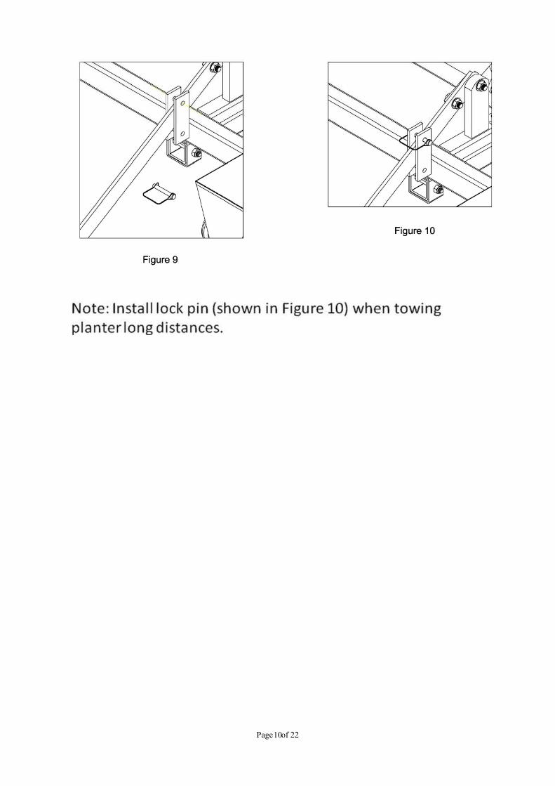
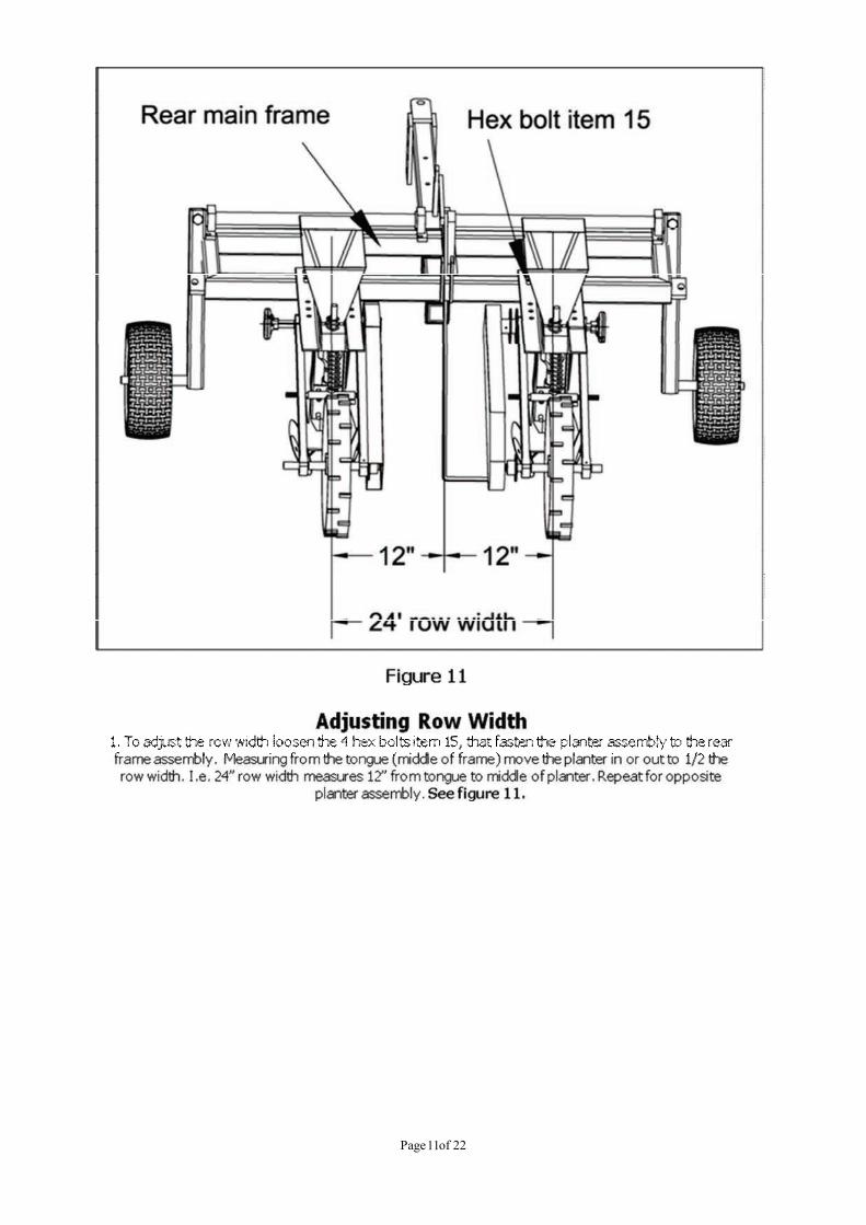
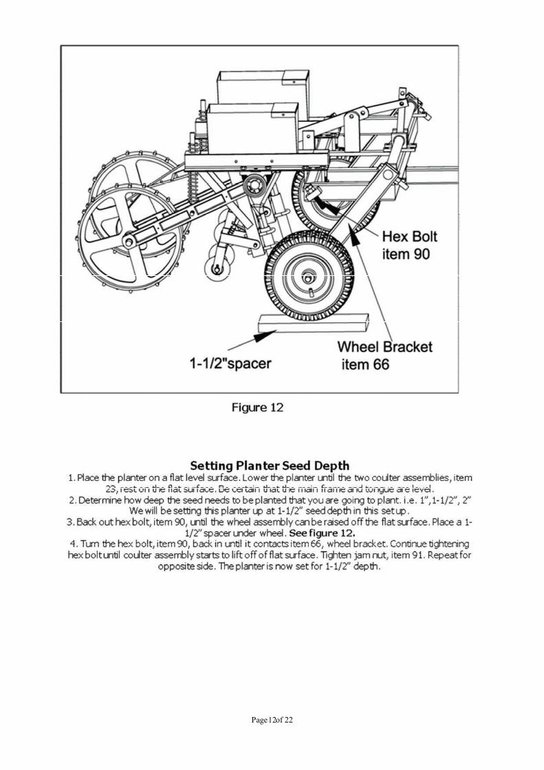
Pages
Legal

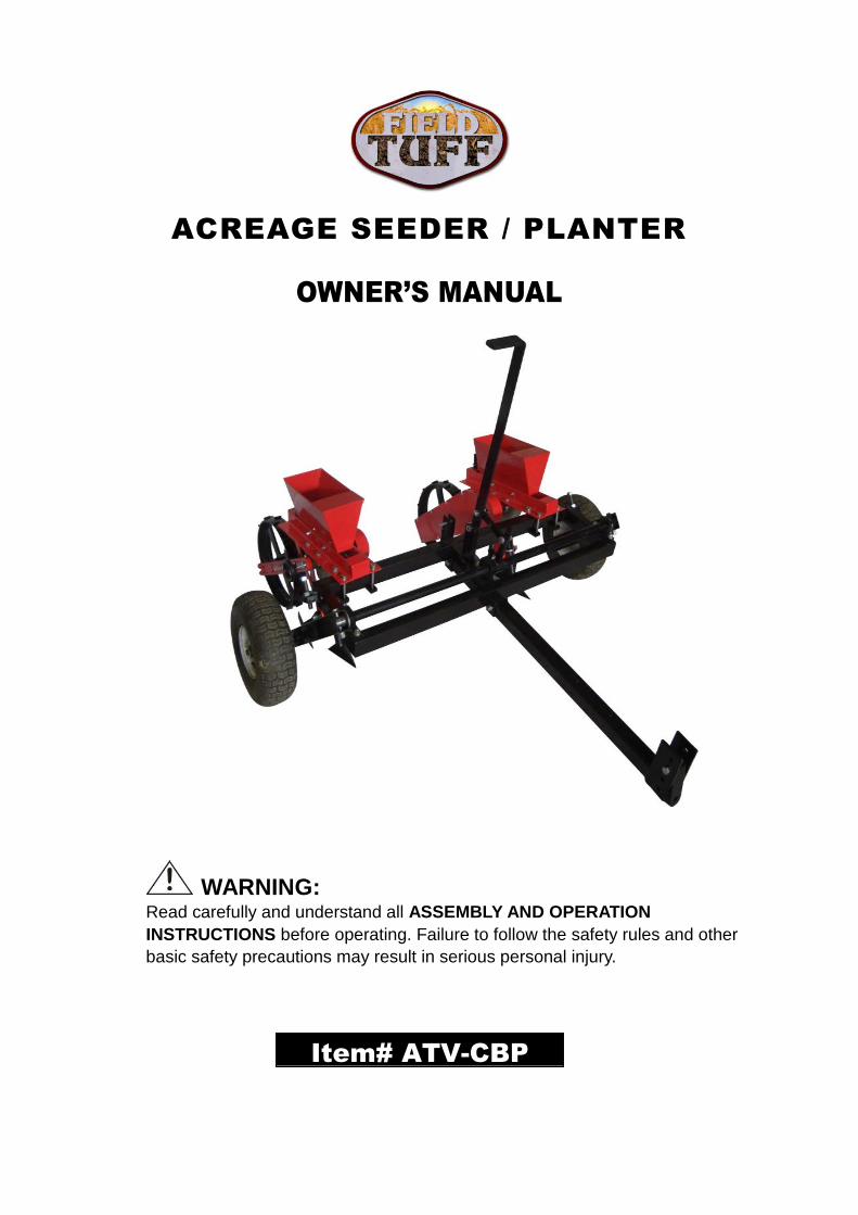
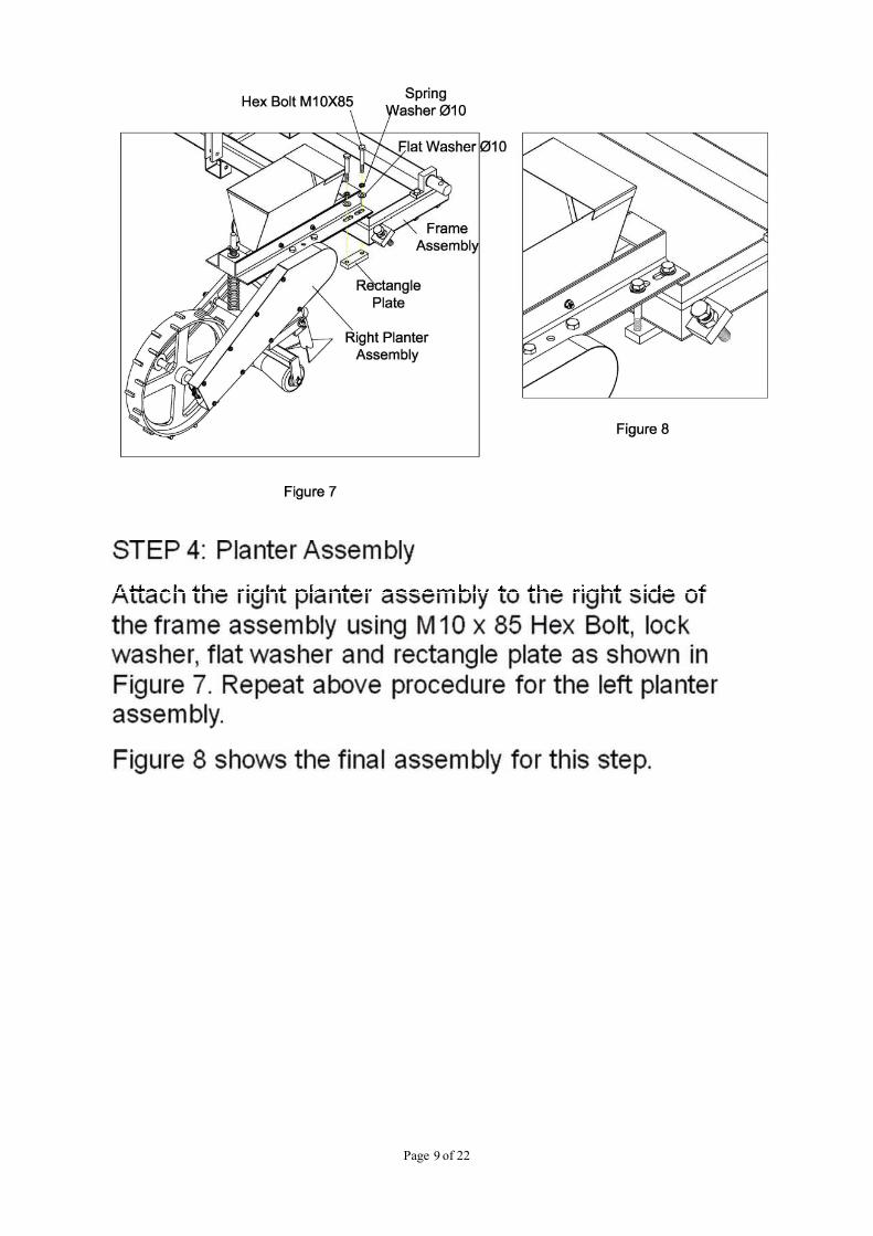
ACREAGE SEEDER / PLANTER
OWNER’S MANUAL
WARNING:Read carefully and understand all ASSEMBLY AND OPERATION
INSTRUCTIONS before operating. Failure to follow the safety rules and other
basic safety precautions may result in serious personal injury.
Item# ATV-CBP
Page of 222
Thank you very much for choosing this product! For future reference, please complete the
owner’s record below:
Model: ___ATV-CBP__ Purchase Date: _______________
Save the receipt, warranty and these instructions. It is important that you read the entire manual
to become familiar with this product before you begin using it.
This product is designed for certain applications only. The manufacturer cannot be responsiblefor issues arising from modification. We strongly recommend this product not be modified and/orused for any application other than that for which it was designed. If you have any questionsrelative to a particular application, DO NOT use the product until you have first contacted us todetermine if it can or should be performed on the product.
For technical questions please call 1-218-943-6296.
INTENDED USE
Planter is designed for planting small feed plots or hobby farm.
TECHNICAL SPECIFICATIONS
Manual lift for raising and lowering13" Pneumatic tiresAdjustable row width from 8"-36.6"Ground DrivenMeasurements of hopper: 12"x6" at top, 10"x2" at bottom, 8" deep.22 bushels/hopper, 32 cups/hopper, 1.75 gallons
GENERAL SAFETY RULES
WARNING: Read and understand all instructions. Failure to follow all instructions listed
below may result in serious injury.
CAUTION: Do not allow persons to operate or assemble this planter until they have
read this manual and have developed a thorough understanding of how the planter works.
WARNING: The warnings, cautions, and instructions discussed in this instruction
manual cannot cover all possible conditions or situations that could occur. It must be
understood by the operator that common sense and caution are factors which cannot be built into
this product, but must be supplied by the operator.
SAVE THESE INSTRUCTIONS
Page of 223
WORK AREA
• Keep work area clean, free of clutter and well lit. Cluttered and dark work areas can cause
accidents.
• Keep children and bystanders away while operating the planter. Distractions can cause you to
lose control, so visitors should remain at a safe distance from the work area.
• Be aware of all power lines, electrical circuits, water pipes and other mechanical hazards in
your work area, particularly those hazards below the work surface hidden from the operator’s
view that may be unintentionally contacted and may cause personal harm or property damage.
• Be alert of your surroundings. Using the planter in confined work areas may put you in
danger.
PERSONAL SAFETY
• Stay alert, watch what you are doing and use common sense when using the planter. Do not
use the planter while you are tired or under the influence of drugs, alcohol or medication. A
moment of inattention while operating the planter may result in serious personal injury.
• Dress properly. Do not wear loose clothing, dangling objects, or jewelry. Keep your hair,
clothing and gloves away from moving parts. Loose clothes, jewelry or long hair can be caught
in moving parts.
• Use safety apparel and equipment. Use safety goggles or safety glasses with side shields
which comply with current national standards, or when needed, a face shield. Use a dust mask
in dusty work conditions. This applies to all persons in the work area. Also use non-skid safety
shoes, hardhat, gloves, dust collection systems, and hearing protection when appropriate.
PLANTER USE AND CARE
• Do not modify the planter in any way. Unauthorized modification may impair the function
and/or safety and could affect the life of the equipment. There are specific applications for which
the planter was designed.
• Always check of damaged or worn out parts before using the planter. Broken parts will
affect the planter operation. Replace or repair damaged or worn parts immediately.
• Do not exceed the planter load capacity.
• Distribute the load evenly. Uneven loads may cause the planter to tip, resulting in personal
injury to the operator or others.
• Use the planter on flat and level surfaces capable of supporting the planter and its maximum
load. Pulling or pushing a load on a slanted or uneven surface can result in loss of control.
• Store idle planter. When planter is not in use, store it in a secure place out of the reach of
children. Inspect it for good working condition prior to storage and before re-use.
Page of 224
HOBBY SEED PLANTER
(Patent Pending)
ASSEMBLY AND OPERATING MANUAL
PRE-ASSEMBLY:
Approximate assembly time of this product is 1 hour.
Helpful Tip: Read all instructions before starting to assemble.
TOOLS REQUIRED FOR ASSEMBLY
(2) 14mm Wrenches
(1) 24mm Wrench
(2) 19mm Wrenches
REMOVE ALL PARTS FROM CARTONS
Remove the hardware packs and all parts from the cartons.
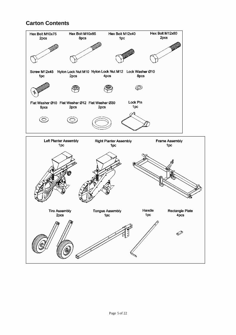
Layout and identify parts included in carton contents. (See parts
listing below)
Layout and identify parts included in the hardware pack. (See
parts listing below)
IF ANY PARTS ARE MISSING FROM PACKAGING
Contact TG at 218-943-6296 for missing hardware or
instructions.
Page of 225
Carton Contents
Page of 226
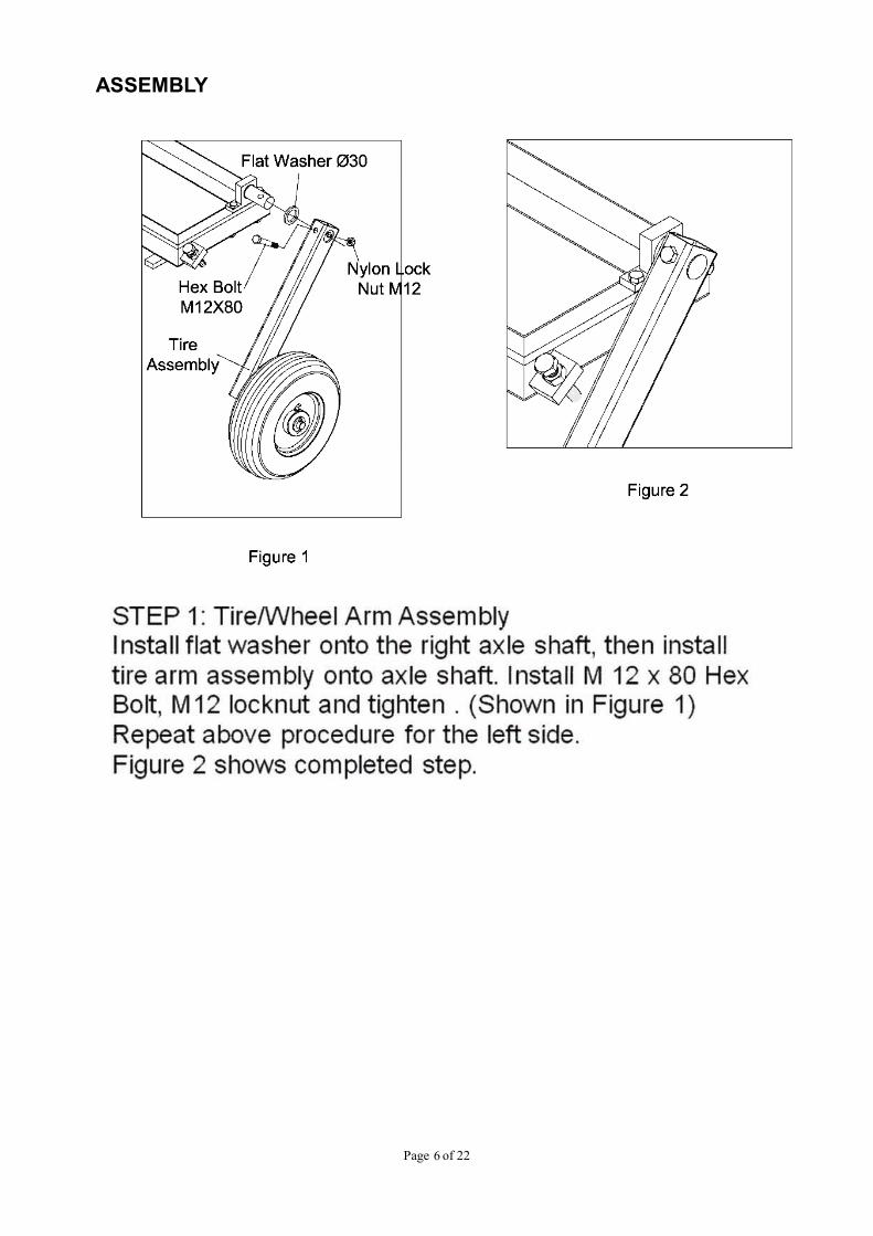
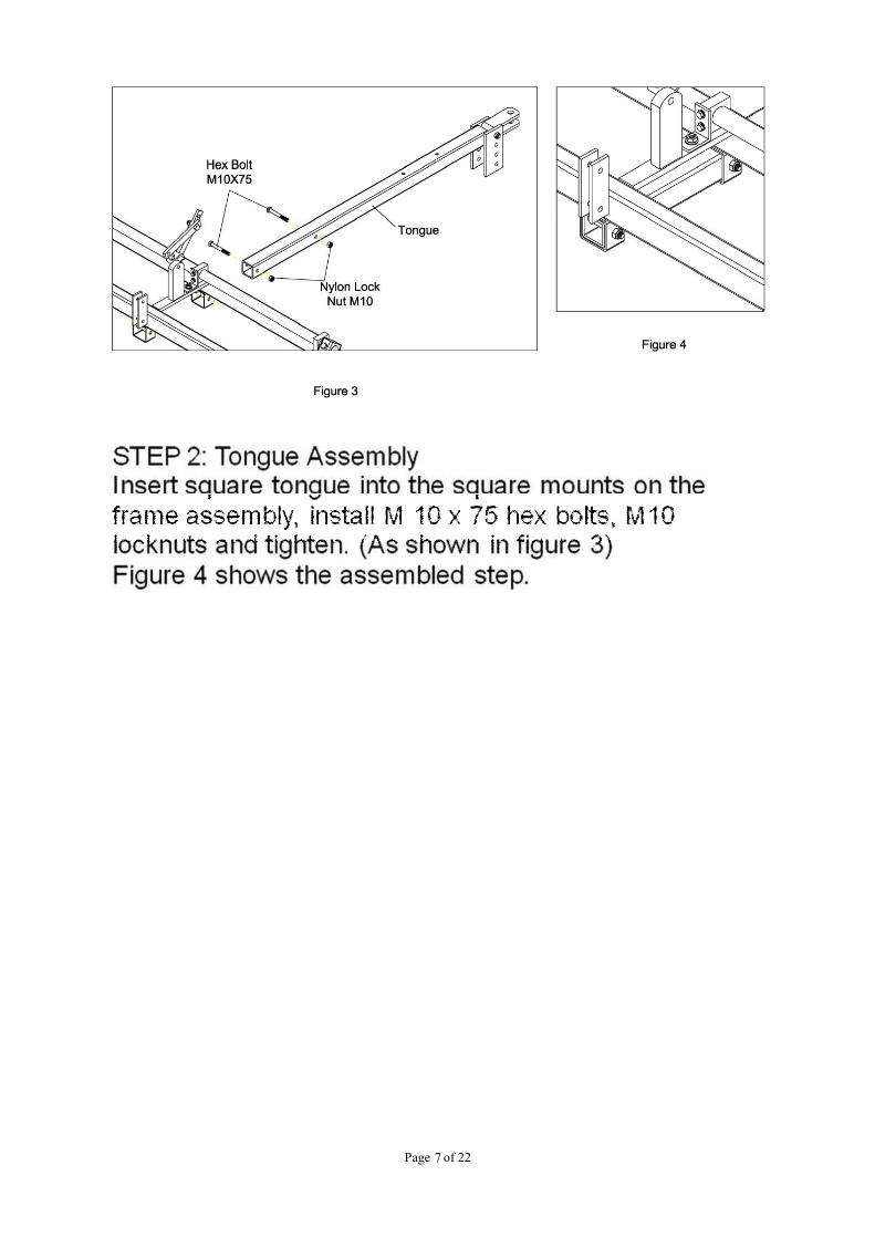
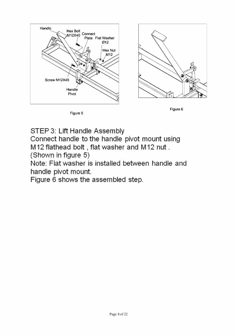
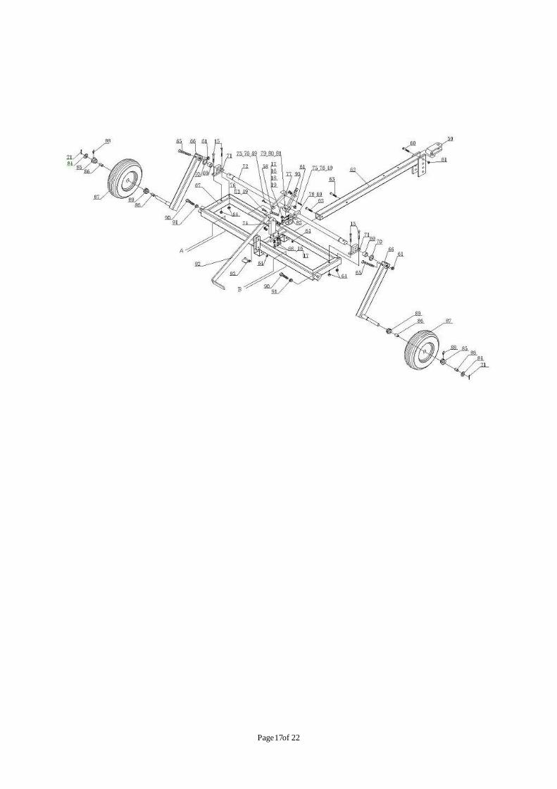
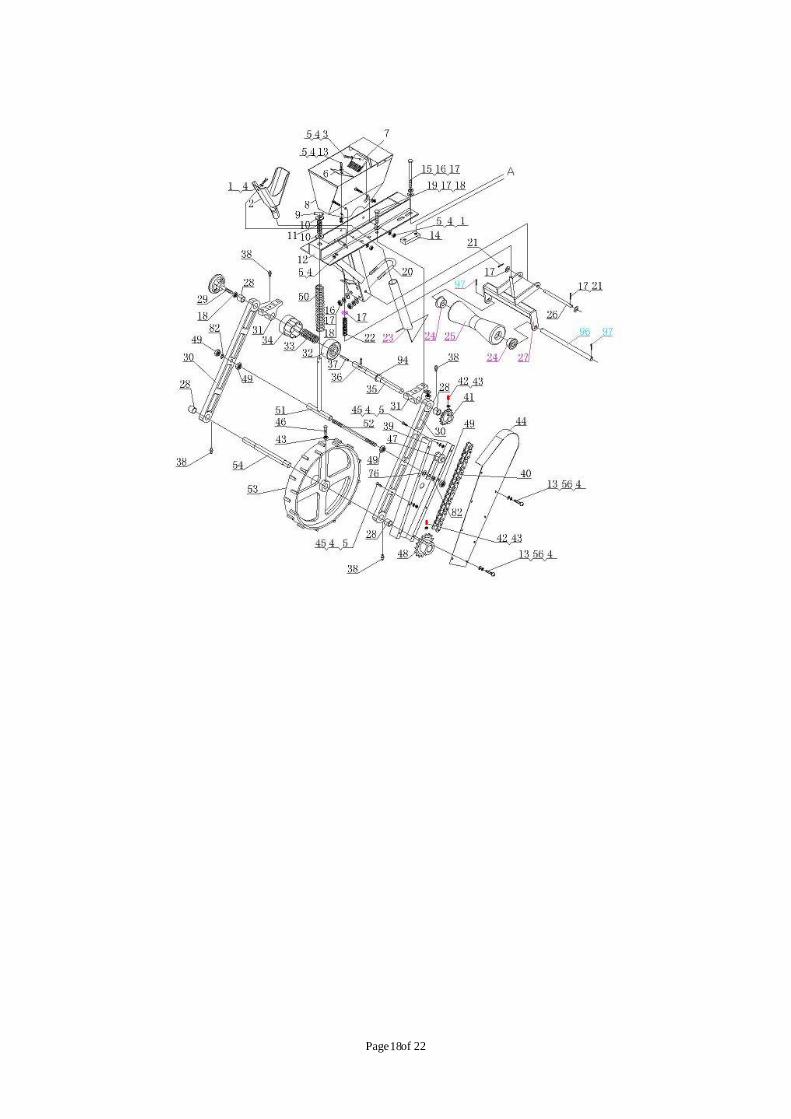
ASSEMBLY
Page of 227
Page of 228
Page of 229
Page of 2210
Page of 2211
Page of 2212
Page of 2213
Page of 2214
Page of 2215
Page of 2216
Problem Solution
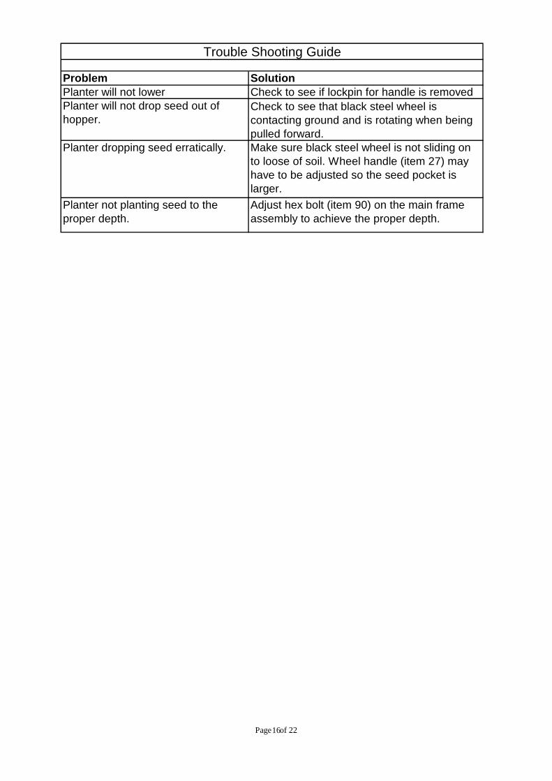
Trouble Shooting Guide
Planter will not lower Check to see if lockpin for handle is removed
Planter not planting seed to theproper depth.
Adjust hex bolt (item 90) on the main frameassembly to achieve the proper depth.
Check to see that black steel wheel iscontacting ground and is rotating when beingpulled forward.
Planter will not drop seed out ofhopper.
Make sure black steel wheel is not sliding onto loose of soil. Wheel handle (item 27) mayhave to be adjusted so the seed pocket islarger.
Planter dropping seed erratically.
Page of 2217
Page of 2218

Page of 2219
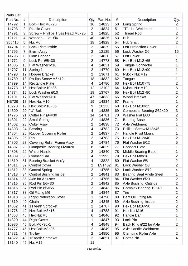
DIAGRAM AND PARTS LIST
Page of 2220
Parts List
Part No. # Description Qty. Part No. # Description Qty.
14792 1 Bolt - Hex M6×20 10 14823 50 Long Spring 2
14793 2 Plastic Cover 2 14824 51 "T" tube Weldment 1
14791 3 Screw – Phillips Truss Head M6×25 2 14825 52 Thread Rod 2
12121 4 Washer – Flat Ø6 40 14826 53 Hub 2955416 5 Nut M6 18 14828 54 Hub Shaft 2
14794 6 Back Plate inside 2 14829 55 Left Protection Cover 1
14795 7 Brush Assy 2 12125 56 Lock Washer Ø6 16
14796 8 Corn Hopper 2 14830 57 Left Cover 1
14772 9 Lock Pin Ø5×30 2 14778 58 Hex Bolt M12×65 1
14305 10 Flat Washer M16 4 14831 59 Tongue Connector 1
14797 11 Spring 1 2 14779 60 Hex Bolt M12×90 1
14798 12 Hopper Bracket 2 13671 61 Nylock Nut M12 4
14789 13 Phillips Screw M6×12 18 14832 62 Tongue 1
14799 14 Rectangle Plate 4 14780 63 Hex Bolt M10×75 214773 15 Hex Bolt M10×85 12 12102 64 Nylock Nut M10 6
14774 15 Lock Washer Ø10 19 13767 65 Hex Bolt M12×80 2
12101 17 Flat Washer Ø10 47 14833 66 Wheel Bracket 2
NB729 18 Hex Nut M10 19 14834 67 Frame 1
13273 19 Hex Bolt M10×35 9 10233 68 Hex Bolt M10×25 2
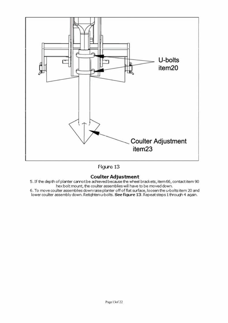
14800 20 "U" Bolt 4 14835 69 Composite Bearing Ø32×20 3
14775 21 Cotter Pin Ø4×30 14 14781 70 Washer Flat Ø30 2
14801 22 Small Spring 2 14836 71 Bearing Base 2
14802 23 Colter Assy 2 14838 72 Axle Weldment 1
14803 24 Bearing 4 14782 73 Phillips Screw M12×45 114804 25 Rubber Covering Roller 2 14837 74 Handle Pivot Mount 1
14805 26 Pin 2 14783 75 Hex Bolt M12×40 2
14806 27 Covering Roller Frame Assy 2 14784 76 Flat Washer Ø12 5
14807 28 Composite Bearing Ø20×20 8 14839 77 Connect Plate 1
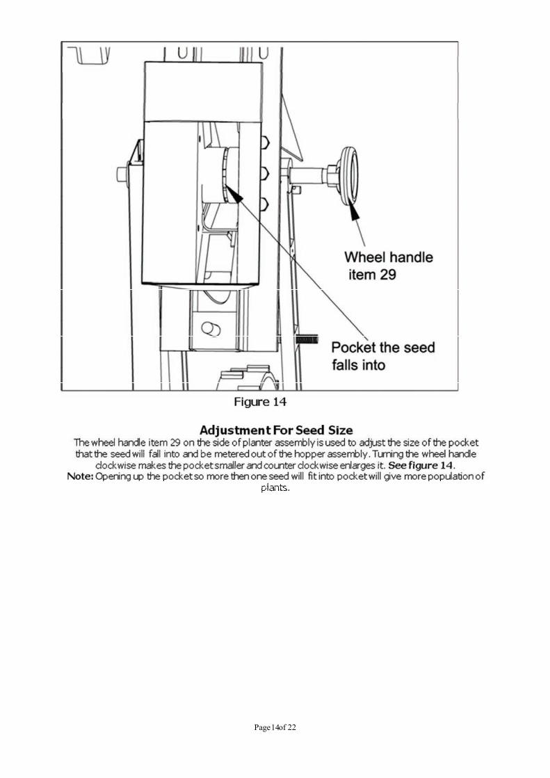
14808 29 Wheel Handle 2 14840 78 Middle Bearing Base 1
14809 30 Connect Bar 4 11993 79 Hex Bolt M8×16 2
14810 31 Bearing Bracket Ass'y 4 13822 80 Flat Washer Ø8 2
14811 32 Control Cover 2 LS1402 81 Lock Washer Ø8 2
14812 33 Control Spring 2 14785 82 Lock Washer Ø12 4
14813 34 Control Bushing Inside 2 14841 83 Bearing Seat Angle Steel 1
14814 35 Axle for Adjuster 2 14786 84 Flat Washer Ø20 214815 36 Rod Pin Ø5×30 2 14842 85 Axle Bushing, Outside 2
14816 37 Rod Pin Ø6×55 2 14843 86 Complex Bearing 19×40 4
14817 38 Oil Fitting M6 8 14844 87 Tire 2
14818 39 Right Protection Cover 1 14790 88 Bent Oil Fitting M6 2
14819 40 Chain 2 14845 89 Axle Bushing, Inside 2
14852 41 11 teeth Sprocket 2 14787 90 Hex Bolt M16×90 2
14776 42 Hex Bolt M8×16 4 14788 91 Hex Nut M16 2
14853 43 Hex Nut M8 6 14846 92 Handle Bar 1
14820 44 Right Cover 1 14847 93 Lock Pin 1
10936 45 Bolt M6×30x1 4 14848 94 Back Ring Ø22 for Axle 214777 46 Hex Bolt M8×35 2 14849 95 Axle Handle Weldment 1
14821 47 Trolley 2 14850 96 Clamping Roller Axle 2
14822 48 16 teeth Sprocket 2 14851 97 Cotter Pin 4
13140 49 Nut M12 11
Page of 2221
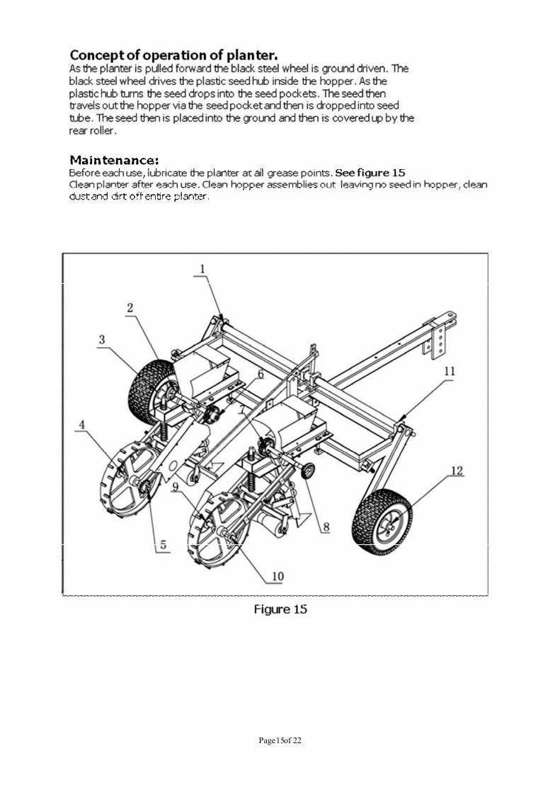
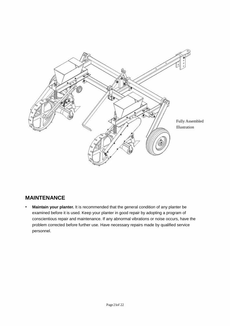
MAINTENANCE
• Maintain your planter. It is recommended that the general condition of any planter be
examined before it is used. Keep your planter in good repair by adopting a program of
conscientious repair and maintenance. If any abnormal vibrations or noise occurs, have the
problem corrected before further use. Have necessary repairs made by qualified service
personnel.
Fully Assembled
Illustration

Page of 2222
For replacement parts and technical questions, please call 1-218-943-6296.
WARRANTY
One-year limited warranty
TG
PO BOX 203
Miltona, MN 56354
Made in CHINA
Top Related