


Languages
Pages
Legal


Greater Strength & Reduced Sag
Increased Spans on Fewer / Shorter Structures
Twice the Capacity of AAC, ACSR & others
Reduced Line Losses by 25 to 40%
Decreased Fuel Consumption & Emissions
Improved Longevity
The High-Capacity, Low-Sag ACCC® Conductor Offers:
& Reduced Life Cycle Costs
…And, its been installed by over 100 utilities at more than 260 project sites. This is not a novelty. This is proven and appropriate technology for our modern grid

The ACCC® Conductor
Its hybrid carbon fiber core is 70% lighter and 50% stronger than steel. Its has a coefficient-of-thermal-expansion about 10 times less than steel. This allows the use of 28% more aluminum which helps increase capacity, improve efficiency & mitigate thermal sag.
Modern Technology for a Modern Grid

Proven Carbon Fiber Technology
… As so many other industries have, especially in highly demanding applications

0
10
20
30
40
50
60
70
80
0 20 40 60 80 100 120 140 160 180 200 220 240 260
Cab
le S
ag
(In
ch
es)
Temperature (C)
ACCC
GAP
Invar
ACCR
ACSS
ACSR
A Conductor Comparison
Comparison testing performed by Hydro One on a 65 meter span, 1600 amps, Drake size
Cooler operating temperatures underscore improved efficiency and reduced losses

1. Developed & Tested the Composite Core
2. Tested Electrical Properties of the Conductor
3. Developed & Tested Ancillary Hardware
4. Assessed Environmental Exposure and Longevity
5. Evaluated Conventional Installation Procedures
7. Commercially Deployed in 2005
8. ISO Certified in 2006
The Substantial Path to ACCC® Deployment
The ACCC® conductor is produced in association with ten licensed stranding partners
In consultation with several International Utilities and laboratories, CTC Global:

Core Testing: 2.1.1 Tensile Testing 2.1.2 Flexural, Bending & Shear Tests 2.1.3 Sustained Load Tests 2.1.4 Tg Tests 2.1.5 CTE Measurements 2.1.6 Shear Testing 2.1.7 Impact and Crush Testing 2.1.8 Torsion Testing 2.1.9 Notched Degradation Testing 2.1.10 Moisture Resistance Testing 2.1.11 Long Term Thermal Testing 2.1.12 Sustained Load Thermal Testing 2.1.13 Cyclic Thermal Testing 2.1.14 Specific Heat Capacity Testing 2.1.15 High Temperature Short Duration 2.1.16 High Temperature Core Testing 2.1.17 Thermal Oxidation Testing 2.1.18 Brittle Fracture Testing 2.1.19 UV Testing 2.1.20 Salt Fog Exposure Tests 2.1.21 Creep Tests 2.1.22 Stress Strain Testing 2.1.24 Micrographic Analysis 2.1.25 Dye Penetrant Testing 2.1.26 High Temperature Shear Testing 2.1.27 Low Temperature Shear Testing
Mechanical Conductor Testing: 2.2.28 Stress Strain Testing 2.2.29 Creep Testing 2.2.30 Aeolian Vibration Testing 2.2.31 Galloping Tests 2.2.32 Self Damping Tests 2.2.33 Radial Impact and Crush Tests 2.2.34 Turning Angle Tests 2.2.35 Torsion Tests 2.2.36 High Temperature Sag Tests 2.2.37 High Temperature Sustained Load 2.2.38 High Temperature Cyclic Load Tests 2.2.39 Cyclic Ice Load Tests 2.2.40 Sheave Wheel Tests 2.2.41 Ultimate Strength Tests 2.2.42 Cyclic Thermo-Mechanical Testing 2.2.43 Combined Cyclic Load Testing 2.2.44 Conductor Comparison Testing
Electrical Conductor Testing: 2.3.45 Resistivity Testing 2.3.46 Power Loss Comparison Testing 2.3.47 Ampacity 2.3.48 EMF Measurements 2.3.49 Impedance Comparison Testing 2.3.50 Corona Testing 2.3.51 Radio Noise Testing 2.3.52 Short Circuit Testing 2.3.53 Lightning Strike Testing 2.3.54 Ultra High Voltage AC & DC Testing
Systems & Hardware Testing: 2.4.55 Current Cycle Testing 2.4.56 Sustained Load Testing 2.4.57 Ultimate Assembly Strength Testing 2.4.58 Salt Fog Emersion Testing 2.4.60 Static Heat Tests 2.4.61 Suspension Clamp Testing 2.4.62 Thermo-Mechanical Testing 2.4.63 Cyclic Load Testing
Field Testing: 2.5.64 Ambient Temperature 2.5.65 Tension, Sag, and Clearance 2.5.66 Conductor Temperature 2.5.67 Electric Current 2.5.68 Wind Speed and Direction 2.5.69 Solar Radiation 2.5.70 Rainfall 2.5.71 Ice Buildup 2.5.72 Splice Resistance 2.5.73 Infrared Measurements 2.5.74 Corona Observations 2.5.75 Electric and Magnetic Fields 2.5.76 Wind and Ice Load Measurements 2.5.77 Vibration Monitoring 2.5.78 Typhoon Test
US / UK / France / Canada / Mexico / China / Brazil / Chile / Belgium / Indonesia / Germany
ACCC® is the Most Tested & Validated Conductor

ACSS ACCC
After Sheave Test, 100 Million Cycles of Vibration, 100 Thousand Cycles of Galloping, and Tensile Test
Testing performed by American Electric Power (AEP) proved the ACCC conductor’s superior resistance to vibration and cyclic load fatigue.
Superior Fatigue Resistance
Torsion Testing
“After completing nearly one and a half
revolutions per foot, my lab guys got
tired of trying to break it so they gave
up.” Craig Pon, Kinectrics
4 Revolutions
54 Revolutions
Note: A core sample intentionally split in half will support 90% of its rated strength

Bending Tests
Conductor bent 90 degrees
10 times around a 6 inch
radius. No visual damage to
core was noted.
Dye penetrant did appear
after 2 minutes in the outer
glass strands showing some
degradation.

Thermal Oxidation Tests
Core sample cooked at 220OC for one year
Oxidation limited to ~60 microns in depth

ACCC® (non destructive testing)

Longevity Assessment by Alpha Star Primary Contractor to Boeing, Airbus and NASA
Substantial Empirical Test Data provided the basis for high-level & very accurate computer modeling
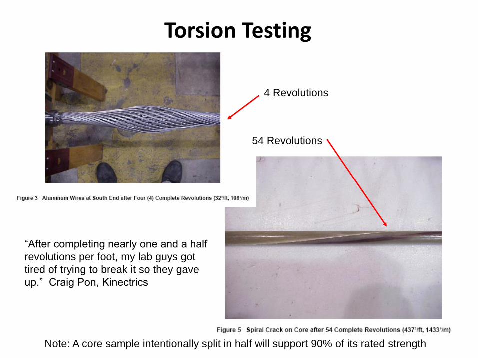
Substantial Experience 22,000 km at 260 project sites
Over 35,000 Dead-Ends & Splices in Service at over 260 Project Sites
Countries:
• USA • China • France • UK • Poland • Spain • Portugal • Mexico • Chile • Qatar • Indonesia • Belgium • Brazil • Germany • South Africa • South Korea • Russia • India • Costa Rica* • Columbia • Congo • Mozambique • Netherlands* • Nigeria* • Vietnam
US Utilities:
• AEP • APS • PacifiCorp • NV Energy • Austin Energy • Xcel Energy • MI PUD • KS PUD • KAMO • OG&E • Ozark Electric • WAPA • STEC • Entergy • Riverside PUD • Florida Power & Light • Keys Energy • Progress Energy • Mohave Electric • SCANA • National Grid • Alexandria (LA) PUD

Utah, USA
Reconductor Project Project Name: PacifiCorp 90 South to Oquirrh, Utah Project Goal: Increase Ampacity (use existing structures) Conductor Size: Drake Conductor Length: 30 km Voltage: 138 kV Energized: 2005 Over 100 existing structures saved

Kansas, USA
New Line Project Name: Kingman to Cunningham, Kansas Project Goal: Install New Line Conductor Size: Hawk Conductor Length: 108 km Voltage: 34.5 kV Energized: 2006
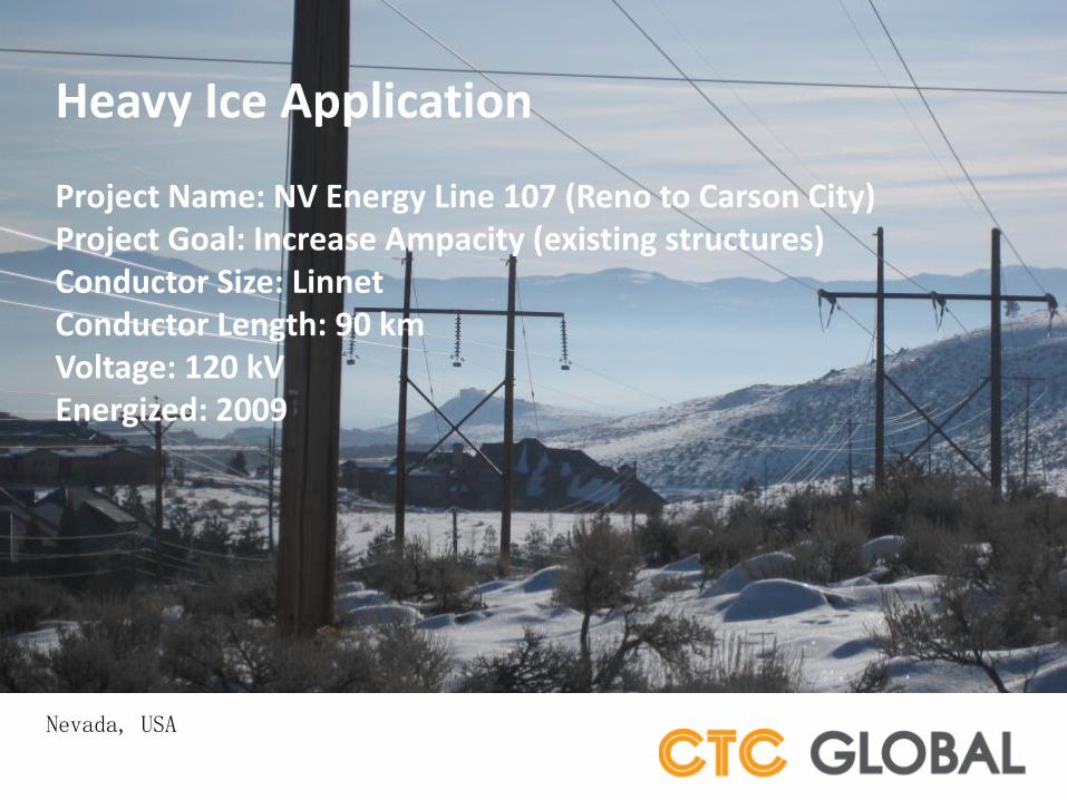
Nevada, USA
Heavy Ice Application Project Name: NV Energy Line 107 (Reno to Carson City) Project Goal: Increase Ampacity (existing structures) Conductor Size: Linnet Conductor Length: 90 km Voltage: 120 kV Energized: 2009
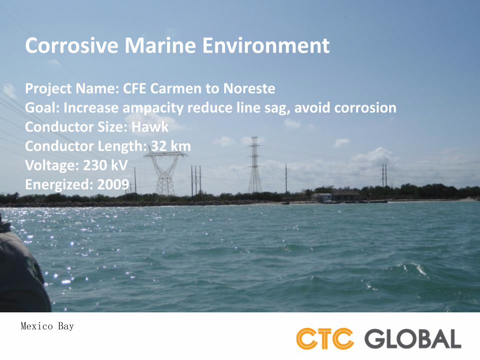
Mexico Bay
Corrosive Marine Environment Project Name: CFE Carmen to Noreste Goal: Increase ampacity reduce line sag, avoid corrosion Conductor Size: Hawk Conductor Length: 32 km Voltage: 230 kV Energized: 2009

Chile
Long Span Application Project Name: Chilectra El Salto to Torre 8 Line Project Goal: Increase Ampacity – (existing structures) Conductor Size: Linnet Conductor Length: 28 km Voltage: 110 kV Energized: 2009

Spain
Wind Farm Link Project Name: NEO Energia 80 turbine upgrade Project Goal / Type: Increase Ampacity (existing structures) Conductor Size: Amsterdam Conductor Length: 57 km Voltage: 66 kV Energized: 2008
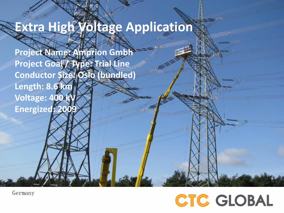
Germany
Extra High Voltage Application Project Name: Amprion Gmbh Project Goal / Type: Trial Line Conductor Size: Oslo (bundled) Length: 8.6 km Voltage: 400 kV Energized: 2009
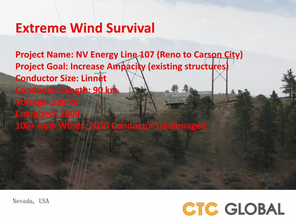
Nevada, USA
Extreme Wind Survival Project Name: NV Energy Line 107 (Reno to Carson City) Project Goal: Increase Ampacity (existing structures) Conductor Size: Linnet Conductor Length: 90 km Voltage: 120 kV Energized: 2009 100+ mph Winds: 2010 Conductor Undamaged

Nevada, USA
Fire Storm Survival Project Name: NV Energy Line 107 (Reno to Carson City) Project Goal: Increase Ampacity (existing structures) Conductor Size: Linnet Conductor Length: 90 km Voltage: 120 kV Energized: 2009 Firestorm: 2012 – ACCC CONDUCTOR UNDAMAGED
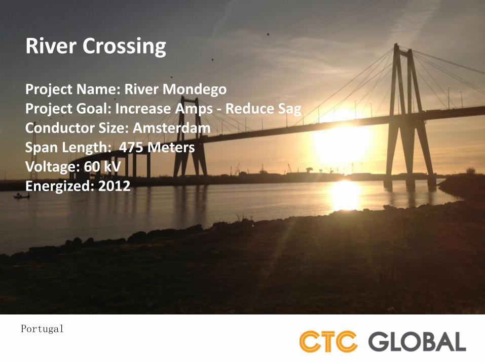
Portugal
River Crossing Project Name: River Mondego Project Goal: Increase Amps - Reduce Sag Conductor Size: Amsterdam Span Length: 475 Meters Voltage: 60 kV Energized: 2012

Fujian Provence, China
Typhoon Survival (2,600’ spans)ED

Tornado Toughness

UK France
California
Kansas
Ice & Wind Load Testing
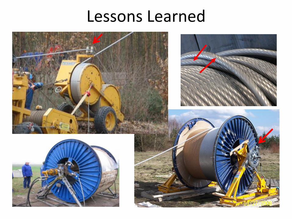
Lessons Learned

Installation Methods

Installation Equipment

Hardware Components

Installation Training and Support
Check out our installation Training Videos on YouTube

A few of CTC’s International Customers:
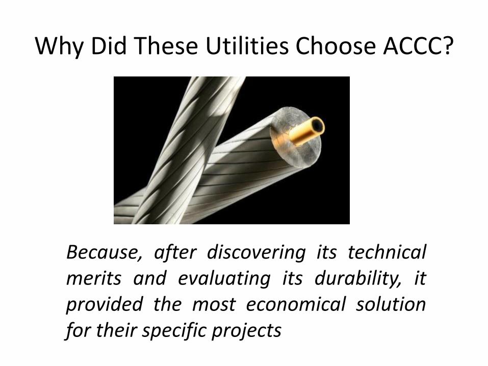
Why Did These Utilities Choose ACCC?
Because, after discovering its technical merits and evaluating its durability, it provided the most economical solution for their specific projects
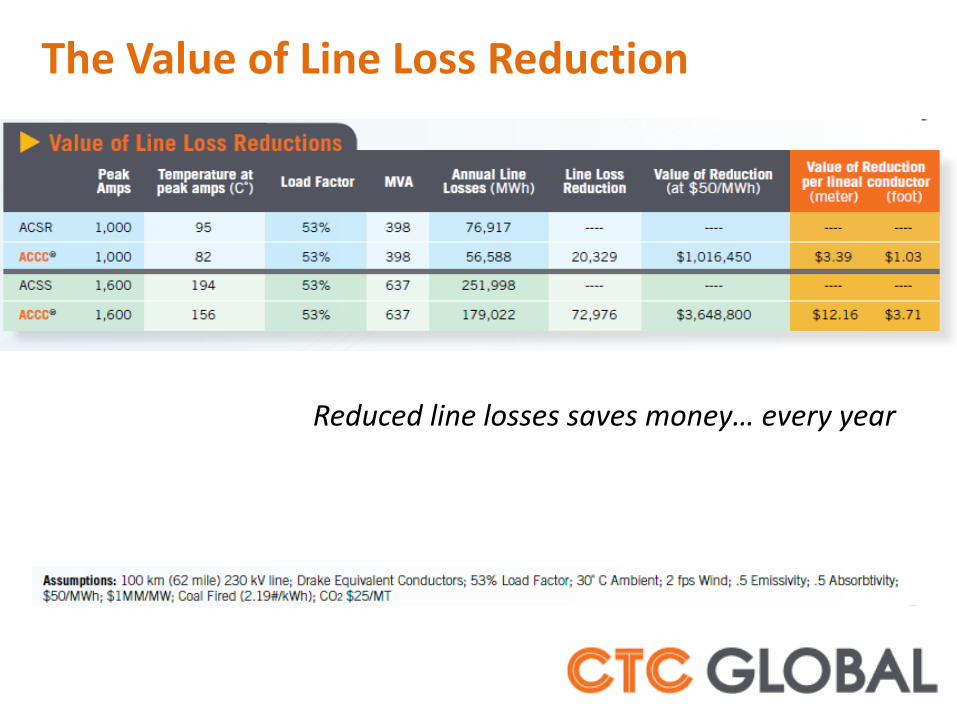
The Value of Line Loss Reduction
Reduced line losses saves money… every year
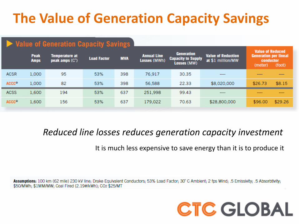
The Value of Generation Capacity Savings
Reduced line losses reduces generation capacity investment
It is much less expensive to save energy than it is to produce it

The Value of Emission Reduction
Reduced line losses reduces fuel consumption …and associated emissions

ISO Certified Production

• Over 40 standard conductor sizes • New ULS conductors being introduced • Design & Engineering Support • 24/7 Customer Service • Installation Training & Support • Extensive Engineering Database
GLOBAL Support
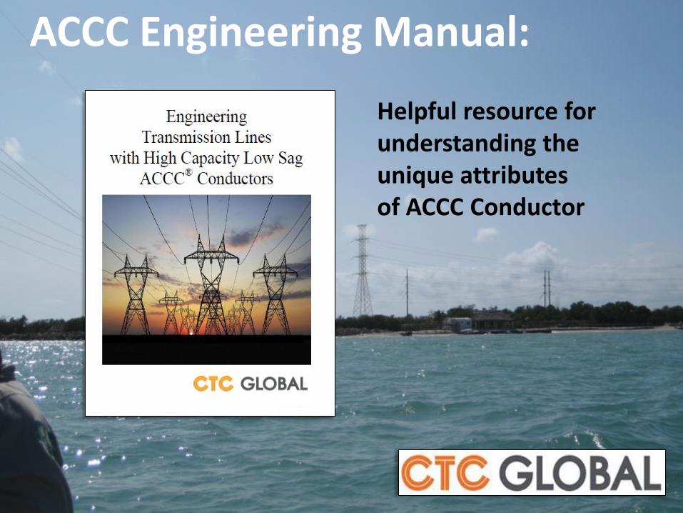
ACCC Engineering Manual:
Helpful resource for understanding the unique attributes of ACCC Conductor
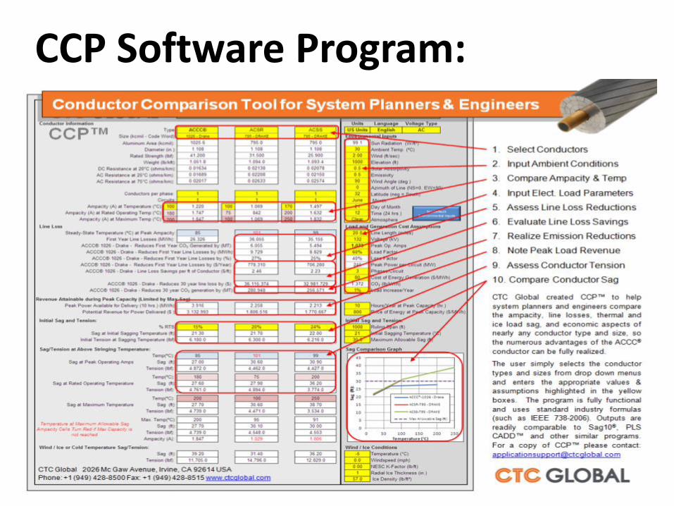
CCP Software Program:

Stay Informed with our Monthly Newsletters:

• Headquartered in Irvine, California
• R&D began in 2002
• Privately held Delaware Corporation
• ACCC® Commercially Deployed in 2005
• ISO Certified Production in 2006
• 18 Global Stranding Partners
• Over 22,000 km at 260 project sites
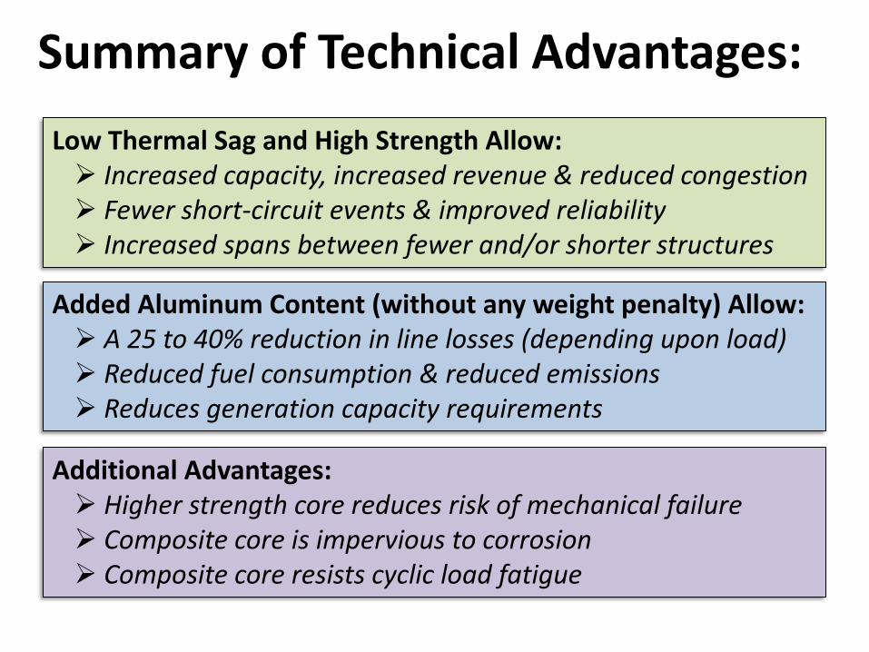
Low Thermal Sag and High Strength Allow: Increased capacity, increased revenue & reduced congestion Fewer short-circuit events & improved reliability Increased spans between fewer and/or shorter structures
Added Aluminum Content (without any weight penalty) Allow: A 25 to 40% reduction in line losses (depending upon load) Reduced fuel consumption & reduced emissions Reduces generation capacity requirements
Additional Advantages: Higher strength core reduces risk of mechanical failure Composite core is impervious to corrosion Composite core resists cyclic load fatigue
Summary of Technical Advantages:

ACCC® Conductor
Improving the Efficiency, Reliability and Capacity of the Grid
CTC Global 2026 McGaw Avenue Irvine, California 92614 USA +1 (949) 428-8500 www.ctcglobal.com
Top Related