


Languages
Pages
Legal

Power and productivity
for a better world™
AC 800MPROFIBUS DPConfiguration
System Version 6.0


AC 800M PROFIBUS DPConfiguration
System Version 6.0
NOTICEThis document contains information about one or more ABB products and may include a description of or a reference to one or more standards that may be generally relevant to the ABB products. The presence of any such description of a standard or reference to a standard is not a representation that all of the ABB products referenced in this document support all of the features of the described or ref-erenced standard. In order to determine the specific features supported by a particular ABB product, the reader should consult the product specifications for the particular ABB product.
ABB may have one or more patents or pending patent applications protecting the intellectual property in the ABB products described in this document.
The information in this document is subject to change without notice and should not be construed as a commitment by ABB. ABB assumes no responsibility for any errors that may appear in this document.
Products described or referenced in this document are designed to be connected, and to communicate information and data via a secure network. It is the sole responsibility of the system/product owner to provide and continuously ensure a secure connection between the product and the system network and/or any other networks that may be connected.
The system/product owners must establish and maintain appropriate measures, including, but not lim-ited to, the installation of firewalls, application of authentication measures, encryption of data, installa-tion of antivirus programs, and so on, to protect the system, its products and networks, against security breaches, unauthorized access, interference, intrusion, leakage, and/or theft of data or information.
ABB verifies the function of released products and updates. However system/product owners are ulti-mately responsible to ensure that any system update (including but not limited to code changes, con-figuration file changes, third-party software updates or patches, hardware change out, and so on) is compatible with the security measures implemented. The system/product owners must verify that the system and associated products function as expected in the environment they are deployed.
In no event shall ABB be liable for direct, indirect, special, incidental or consequential damages of any nature or kind arising from the use of this document, nor shall ABB be liable for incidental or conse-quential damages arising from use of any software or hardware described in this document.
This document and parts thereof must not be reproduced or copied without written permission from ABB, and the contents thereof must not be imparted to a third party nor used for any unauthorized pur-pose.
The software or hardware described in this document is furnished under a license and may be used, copied, or disclosed only in accordance with the terms of such license. This product meets the require-ments specified in EMC Directive 2004/108/EC and in Low Voltage Directive 2006/95/EC.
TRADEMARKSAll rights to copyrights, registered trademarks, and trademarks reside with their respective owners.
Copyright © 2003-2016 by ABB.All rights reserved.
Release: April 2016Document number: 3BDS009030-600 A
3BDS009030-600 A 5
Table of Contents
About This User ManualIntended User...................................................................................................................10
How to Use this User Manual..........................................................................................10
User Manual Conventions ...............................................................................................10
Feature Pack .........................................................................................................11
Warning, Caution, Information, and Tip Icons ....................................................11
Terminology.....................................................................................................................12
Released User Manuals and Release Notes.....................................................................17
Section 1 - Introduction
Section 2 - Functional DescriptionPROFIBUS Basics...........................................................................................................21
Basic Functions DP-V0........................................................................................21
Cyclic Data Communication ...............................................................21
Diagnostics ......................................................................................22
DP Master Class 1 (DPM1) and Class 2 (DPM2)...............................23
System Behavior .................................................................................24
Sync and Freeze Mode ........................................................................24
Monitoring the DP-V0 Communication..............................................25
Multi Master Systems .........................................................................25
Version DP-V1 .....................................................................................................26
Acyclic Data Communication .............................................................26
Alarms and Status Messages ...............................................................27
Redundancy .....................................................................................................................27
Master Redundancy..............................................................................................28
Table of Contents
6 3BDS009030-600 A
Slave Redundancy................................................................................................ 29
Line Redundancy ................................................................................................. 30
Status Handling ............................................................................................................... 31
Status Handling for DP-V1 Master Unit.............................................................. 31
Status Handling for Slave Units........................................................................... 37
Alarms and Events ............................................................................................... 38
Hot Swap ......................................................................................................................... 38
Replacement of CI854/CI854A/CI854B in Non Redundant Configuration........ 39
Replacement of CI854/CI854A/CI854B in Redundant Configuration................ 39
Replacing CI854A with Same Module Type ...................................... 39
Replacing CI854B with Same Module Type ...................................... 39
Replacing CI854A with CI854B......................................................... 39
Replacing CI854B with CI854A......................................................... 40
Hot Configuration in Run (HCIR) .................................................................................. 40
Section 3 - ConfigurationHardware Library ............................................................................................................ 43
Insert PROFIBUS Master Unit........................................................................................ 43
Add Redundancy for Master Unit ................................................................................... 46
Delete Redundancy for Master Unit................................................................................ 47
Firmware Upgrade........................................................................................................... 47
Configure the PROFIBUS Master Unit........................................................................... 49
Hardware Editor................................................................................................... 49
Settings Tab ...................................................................................... 50
Connection Tab ................................................................................... 55
Unit Status Tab.................................................................................... 55
Automatic Calculation of PROFIBUS Master Parameter.................................... 55
Default Values...................................................................................................... 57
Special Settings.................................................................................................... 58
Insert a Slave Unit ........................................................................................................... 59
Add Redundancy for Slave Unit ..................................................................................... 62
Delete Redundancy for Slave Unit .................................................................................. 63
Insert a new Slave Type................................................................................................... 63
Table of Contents
3BDS009030-600 A 7
3BDS009030-600 A 7
Configuration of PA-Devices...........................................................................................65
Connecting PA-Devices via Linking Device LD 800P and SK3 .........................65
PROFIBUS Power Hub SK3................................................................................66
Configuration of PROFIBUS Slave Address .......................................................67
Configuration via DP-V1 .....................................................................................67
Device Management PROFIBUS & HART .........................................................69
Section 4 - Download and Online ModePreconditions ...................................................................................................................71
Download.........................................................................................................................72
Online Changes ....................................................................................................72
Automatic Calculation of PROFIBUS Master Parameters ..................................74
Logfile .............................................................................................................76
Online Data......................................................................................................................76
Behavior of I/O and Communication ..............................................................................77
Insertion and deletion of I/O units .......................................................................77
Connection Error ..................................................................................................77
System Error.........................................................................................................78
Section 5 - CI854 Web serverCI854 Web Server Login Prerequisite .............................................................................79
Web Server Login ................................................................................................80
Enable Javascript for Web Server ........................................................................81
Reset Web Browser Security settings for Web Server .........................................82
CI854 Web Server Security .............................................................................................83
CI854 Web Server Interface ............................................................................................86
CI854 web server Interface Menu Items .........................................................................88
SetAddress............................................................................................................89
LiveList .............................................................................................................91
CycleTime ............................................................................................................92
GeneralStatus .......................................................................................................93
MasterSettings......................................................................................................95
SlaveDiagnosis .....................................................................................................96

Table of Contents
8 3BDS009030-600 A
SlaveConfig.......................................................................................................... 98
Slave-I/O .......................................................................................................... 100
FirmwareInfo ..................................................................................................... 101
HardwareInfo ..................................................................................................... 102
Redundancy Switchover .................................................................................... 103
Errormemory...................................................................................................... 104
Debug, DMJ Buffer ........................................................................................... 105
Debug - Set Log Filter ...................................................................................... 107
Service File ........................................................................................................ 108
Change Password ............................................................................................... 110
Reset Default Password ..................................................................................... 110
Revision HistoryUpdates in Revision Index A......................................................................................... 115
Index

3BDS009030-600 A 9
About This User Manual
This user manual describes the configuration of the PROFIBUS DP-V1 in the 800xA control system using CI854/CI854A/CI854B communication interface.
The main areas covered in this user manual are:
• PROFIBUS functionalities available with CI854/CI854A/CI854B
– Functionality and Feature of CI854 and CI854A firmware are same. However, CI854 does not support Module Redundancy.
– Functionality and Feature of CI854A and CI854B are same. However, the Firmware for CI854 and CI854A is different from CI854B.
• Hardware configuration with the Control Builder M
• Supervision and status visualization of the PROFIBUS
The reader of this manual is expected to have good knowledge of the 800xA control system and the PROFIBUS in general
Any security measures described in this User Manual, for example, for user access, password security, network security, firewalls, virus protection, etc., represent possible steps that a user of an 800xA System may want to consider based on a risk assessment for a particular application and installation. This risk assessment, as well as the proper implementation, configuration, installation, operation, administration, and maintenance of all relevant security related equipment, software, and procedures, are the responsibility of the user of the 800xA System.
This manual does not provide any information about installing the PROFIBUS network. This information is provided in the AC 800M PROFIBUS DP Installation (3BDS009029*) Manual for PROFIBUS DP-V1.

Intended User About This User Manual
10 3BDS009030-600 A
This user manual is not the only source of instruction for PROFIBUS. ABB offers training courses for those who use ABB control systems
Intended UserThis manual is intended for application engineers and for engineers who are planning the design of a PROFIBUS system. The reader should be familiar with Control IT for AC 800M products and the programming tool, Control Builder M. Also the reader should be familiar with the hardware and software functionality of the 800xA system products. Apart from this, the user should have a good PROFIBUS knowledge.
How to Use this User ManualSection 1, Introduction gives a brief overview of PROFIBUS and how it is integrated in the controllers.
Section 2, Functional Description provides detailed information on the PROFIBUS implementation.
Section 3, Configuration describes the configuration of PROFIBUS with the Control Builder M.
Section 4, Download and Online Mode describes the download procedure and the system behavior in case of an error.
Section 5, CI854 Web server describes how to get detailed diagnostic information from the system in case of a serious PROFIBUS error and how to set the slave address for PA devices.
For a list of documentation related to the products described in this user manual, see Released User Manuals and Release Notes on page 17.
User Manual ConventionsMicrosoft Windows conventions are normally used for the standard presentation of material when entering text, key sequences, prompts, messages, menu items, screen elements, etc.
About This User Manual Feature Pack
3BDS009030-600 A 11
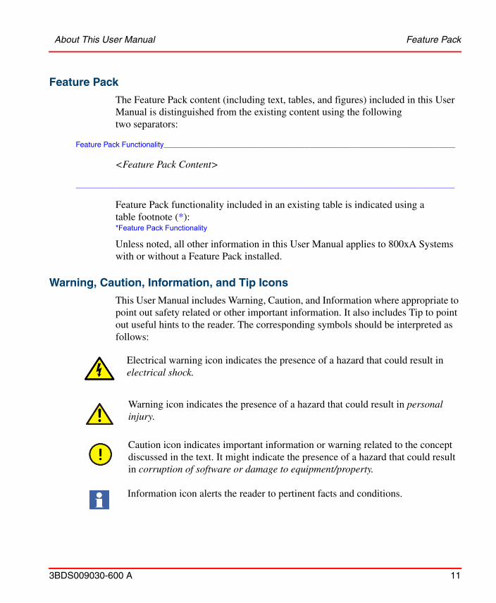
Feature Pack
The Feature Pack content (including text, tables, and figures) included in this User Manual is distinguished from the existing content using the following two separators:
Feature Pack Functionality______________________________________________________________________
<Feature Pack Content>
___________________________________________________________________________________________
Feature Pack functionality included in an existing table is indicated using a table footnote (*):*Feature Pack Functionality
Unless noted, all other information in this User Manual applies to 800xA Systems with or without a Feature Pack installed.
Warning, Caution, Information, and Tip Icons
Electrical warning icon indicates the presence of a hazard that could result in electrical shock.
Warning icon indicates the presence of a hazard that could result in personal injury.
Caution icon indicates important information or warning related to the concept discussed in the text. It might indicate the presence of a hazard that could result in corruption of software or damage to equipment/property.
Information icon alerts the reader to pertinent facts and conditions.
This User Manual includes Warning, Caution, and Information where appropriate to point out safety related or other important information. It also includes Tip to point out useful hints to the reader. The corresponding symbols should be interpreted as follows:
Tip icon indicates advice on, for example, how to design your project or how to use a certain function
Terminology About This User Manual
12 3BDS009030-600 A
Although Warning hazards are related to personal injury, and Caution hazards are associated with equipment or property damage, it should be understood that operation of damaged equipment could, under certain operational conditions, result in degraded process performance leading to personal injury or death. Therefore, fully comply with all Warning and Caution notices.
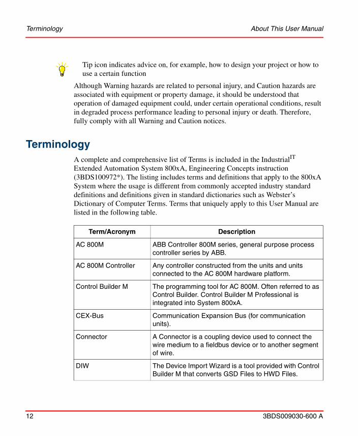
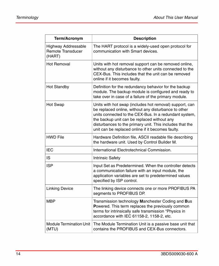
TerminologyA complete and comprehensive list of Terms is included in the IndustrialIT Extended Automation System 800xA, Engineering Concepts instruction (3BDS100972*). The listing includes terms and definitions that apply to the 800xA System where the usage is different from commonly accepted industry standard definitions and definitions given in standard dictionaries such as Webster’s Dictionary of Computer Terms. Terms that uniquely apply to this User Manual are listed in the following table.
Term/Acronym Description
AC 800M ABB Controller 800M series, general purpose process controller series by ABB.
AC 800M Controller Any controller constructed from the units and units connected to the AC 800M hardware platform.
Control Builder M The programming tool for AC 800M. Often referred to as Control Builder. Control Builder M Professional is integrated into System 800xA.
CEX-Bus Communication Expansion Bus (for communication units).
Connector A Connector is a coupling device used to connect the wire medium to a fieldbus device or to another segment of wire.
DIW The Device Import Wizard is a tool provided with Control Builder M that converts GSD Files to HWD Files.
About This User Manual Terminology
3BDS009030-600 A 13
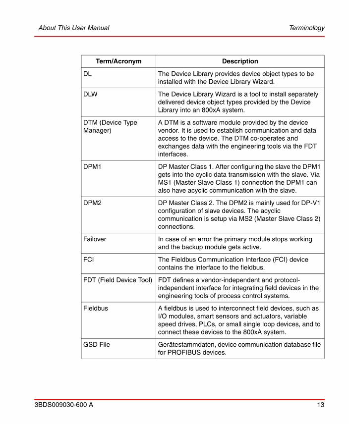
DL The Device Library provides device object types to be installed with the Device Library Wizard.
DLW The Device Library Wizard is a tool to install separately delivered device object types provided by the Device Library into an 800xA system.
DTM (Device Type Manager)
A DTM is a software module provided by the device vendor. It is used to establish communication and data access to the device. The DTM co-operates and exchanges data with the engineering tools via the FDT interfaces.
DPM1 DP Master Class 1. After configuring the slave the DPM1 gets into the cyclic data transmission with the slave. Via MS1 (Master Slave Class 1) connection the DPM1 can also have acyclic communication with the slave.
DPM2 DP Master Class 2. The DPM2 is mainly used for DP-V1 configuration of slave devices. The acyclic communication is setup via MS2 (Master Slave Class 2) connections.
Failover In case of an error the primary module stops working and the backup module gets active.
FCI The Fieldbus Communication Interface (FCI) device contains the interface to the fieldbus.
FDT (Field Device Tool) FDT defines a vendor-independent and protocol-independent interface for integrating field devices in the engineering tools of process control systems.
Fieldbus A fieldbus is used to interconnect field devices, such as I/O modules, smart sensors and actuators, variable speed drives, PLCs, or small single loop devices, and to connect these devices to the 800xA system.
GSD File Gerätestammdaten, device communication database file for PROFIBUS devices.
Term/Acronym Description
Terminology About This User Manual
14 3BDS009030-600 A
Highway Addressable Remote Transducer (HART)
The HART protocol is a widely-used open protocol for communication with Smart devices.
Hot Removal Units with hot removal support can be removed online, without any disturbance to other units connected to the CEX-Bus. This includes that the unit can be removed online if it becomes faulty.
Hot Standby Definition for the redundancy behavior for the backup module. The backup module is configured and ready to take over in case of a failure of the primary module.
Hot Swap Units with hot swap (includes hot removal) support, can be replaced online, without any disturbance to other units connected to the CEX-Bus. In a redundant system, the backup unit can be replaced without any disturbances to the primary unit. This includes that the unit can be replaced online if it becomes faulty.
HWD File Hardware Definition file, ASCII readable file describing the hardware unit. Used by Control Builder M.
IEC International Electrotechnical Commission.
IS Intrinsic Safety
ISP Input Set as Predetermined. When the controller detects a communication failure with an input module, the application variables are set to predetermined values specified by ISP control.
Linking Device The linking device connects one or more PROFIBUS PA segments to PROFIBUS DP.
MBP Transmission technology Manchester Coding and Bus Powered. This term replaces the previously common terms for intrinsically safe transmission “Physics in accordance with IEC 61158-2, 1158-2, etc.
Module Termination Unit (MTU)
The Module Termination Unit is a passive base unit that contains the PROFIBUS and CEX-Bus connectors.
Term/Acronym Description
About This User Manual Terminology
3BDS009030-600 A 15
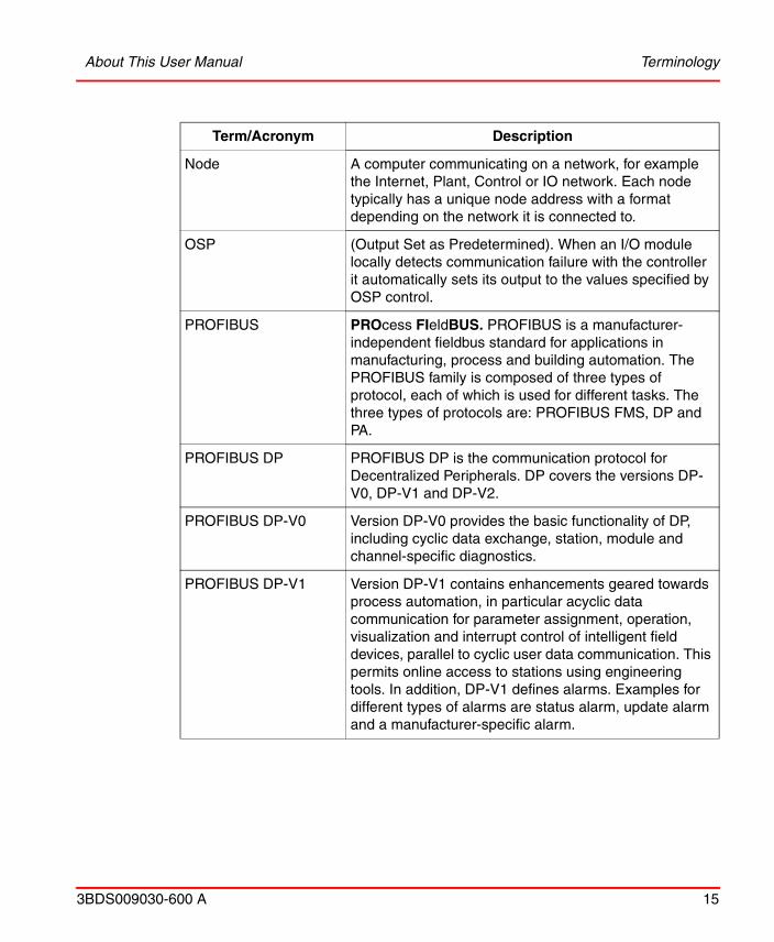
Node A computer communicating on a network, for example the Internet, Plant, Control or IO network. Each node typically has a unique node address with a format depending on the network it is connected to.
OSP (Output Set as Predetermined). When an I/O module locally detects communication failure with the controller it automatically sets its output to the values specified by OSP control.
PROFIBUS PROcess FIeldBUS. PROFIBUS is a manufacturer-independent fieldbus standard for applications in manufacturing, process and building automation. The PROFIBUS family is composed of three types of protocol, each of which is used for different tasks. The three types of protocols are: PROFIBUS FMS, DP and PA.
PROFIBUS DP PROFIBUS DP is the communication protocol for Decentralized Peripherals. DP covers the versions DP-V0, DP-V1 and DP-V2.
PROFIBUS DP-V0 Version DP-V0 provides the basic functionality of DP, including cyclic data exchange, station, module and channel-specific diagnostics.
PROFIBUS DP-V1 Version DP-V1 contains enhancements geared towards process automation, in particular acyclic data communication for parameter assignment, operation, visualization and interrupt control of intelligent field devices, parallel to cyclic user data communication. This permits online access to stations using engineering tools. In addition, DP-V1 defines alarms. Examples for different types of alarms are status alarm, update alarm and a manufacturer-specific alarm.
Term/Acronym Description
Terminology About This User Manual
16 3BDS009030-600 A
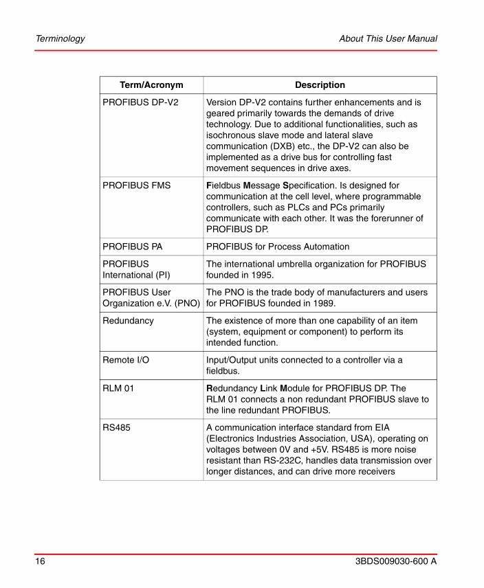
PROFIBUS DP-V2 Version DP-V2 contains further enhancements and is geared primarily towards the demands of drive technology. Due to additional functionalities, such as isochronous slave mode and lateral slave communication (DXB) etc., the DP-V2 can also be implemented as a drive bus for controlling fast movement sequences in drive axes.
PROFIBUS FMS Fieldbus Message Specification. Is designed for communication at the cell level, where programmable controllers, such as PLCs and PCs primarily communicate with each other. It was the forerunner of PROFIBUS DP.
PROFIBUS PA PROFIBUS for Process Automation
PROFIBUS International (PI)
The international umbrella organization for PROFIBUS founded in 1995.
PROFIBUS User Organization e.V. (PNO)
The PNO is the trade body of manufacturers and users for PROFIBUS founded in 1989.
Redundancy The existence of more than one capability of an item (system, equipment or component) to perform its intended function.
Remote I/O Input/Output units connected to a controller via a fieldbus.
RLM 01 Redundancy Link Module for PROFIBUS DP. The RLM 01 connects a non redundant PROFIBUS slave to the line redundant PROFIBUS.
RS485 A communication interface standard from EIA (Electronics Industries Association, USA), operating on voltages between 0V and +5V. RS485 is more noise resistant than RS-232C, handles data transmission over longer distances, and can drive more receivers
Term/Acronym Description

About This User Manual Released User Manuals and Release Notes
3BDS009030-600 A 17
Released User Manuals and Release NotesA complete list of all User Manuals and Release Notes applicable to System 800xA is provided in System 800xA Released User Manuals and Release Notes (3BUA000263*).
System 800xA Released User Manuals and Release Notes (3BUA000263*) is updated each time a document is updated or a new document is released. It is in pdf format and is provided in the following ways:
• Included on the documentation media provided with the system and published to ABB SolutionsBank when released as part of a major or minor release, Service Pack, Feature Pack, or System Revision.
• Published to ABB SolutionsBank when a User Manual or Release Note is updated in between any of the release cycles listed in the first bullet.
A product bulletin is published each time System 800xA Released User Manuals and Release Notes (3BUA000263*) is updated and published to ABB SolutionsBank.
For standards and commercially available PROFIBUS documentation please visit the PROFIBUS Web Site (http://www.profibus.com).
Segment A Segment is a section of a PROFIBUS DP fieldbus that is terminated in its characteristic impedance. Segments can be linked by Repeaters to form a longer PROFIBUS DP fieldbus. Each Segment can include up to 32 devices.
tbit Time a bit needs to be transferred on PROFIBUS. This time depends on the baudrate. tbit = 1/baudrate.
TRS Tool Routing Service, a service that allows the user to use Fieldbus Builder PROFIBUS/HART to configure HART devices, via AC 800M.
Unit A hardware unit, with or without accommodated software.
Term/Acronym Description

Released User Manuals and Release Notes About This User Manual
18 3BDS009030-600 A
3BDS009030-600 A 19
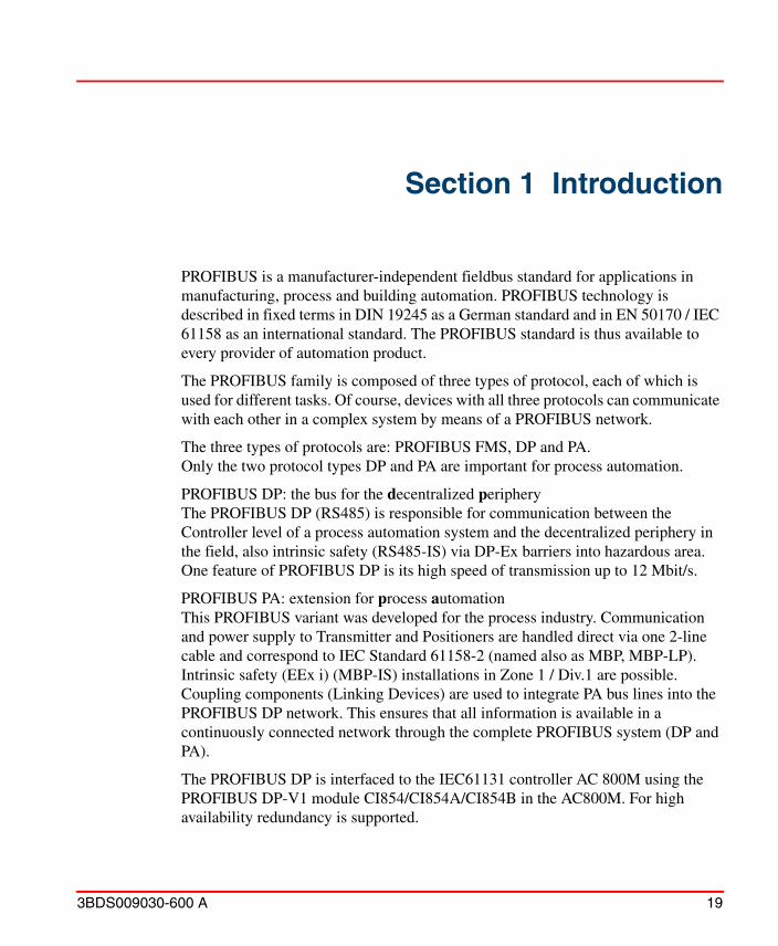
Section 1 Introduction
PROFIBUS is a manufacturer-independent fieldbus standard for applications in manufacturing, process and building automation. PROFIBUS technology is described in fixed terms in DIN 19245 as a German standard and in EN 50170 / IEC 61158 as an international standard. The PROFIBUS standard is thus available to every provider of automation product.
The PROFIBUS family is composed of three types of protocol, each of which is used for different tasks. Of course, devices with all three protocols can communicate with each other in a complex system by means of a PROFIBUS network.
The three types of protocols are: PROFIBUS FMS, DP and PA. Only the two protocol types DP and PA are important for process automation.
PROFIBUS DP: the bus for the decentralized peripheryThe PROFIBUS DP (RS485) is responsible for communication between the Controller level of a process automation system and the decentralized periphery in the field, also intrinsic safety (RS485-IS) via DP-Ex barriers into hazardous area. One feature of PROFIBUS DP is its high speed of transmission up to 12 Mbit/s.
PROFIBUS PA: extension for process automationThis PROFIBUS variant was developed for the process industry. Communication and power supply to Transmitter and Positioners are handled direct via one 2-line cable and correspond to IEC Standard 61158-2 (named also as MBP, MBP-LP). Intrinsic safety (EEx i) (MBP-IS) installations in Zone 1 / Div.1 are possible.Coupling components (Linking Devices) are used to integrate PA bus lines into the PROFIBUS DP network. This ensures that all information is available in a continuously connected network through the complete PROFIBUS system (DP and PA).
The PROFIBUS DP is interfaced to the IEC61131 controller AC 800M using the PROFIBUS DP-V1 module CI854/CI854A/CI854B in the AC800M. For high availability redundancy is supported.
Section 1 Introduction
20 3BDS009030-600 A
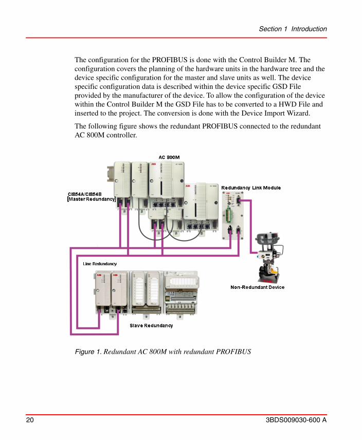
The configuration for the PROFIBUS is done with the Control Builder M. The configuration covers the planning of the hardware units in the hardware tree and the device specific configuration for the master and slave units as well. The device specific configuration data is described within the device specific GSD File provided by the manufacturer of the device. To allow the configuration of the device within the Control Builder M the GSD File has to be converted to a HWD File and inserted to the project. The conversion is done with the Device Import Wizard.
The following figure shows the redundant PROFIBUS connected to the redundant AC 800M controller.
Figure 1. Redundant AC 800M with redundant PROFIBUS
3BDS009030-600 A 21
Section 2 Functional Description
PROFIBUS Basics
Basic Functions DP-V0
Cyclic Data Communication
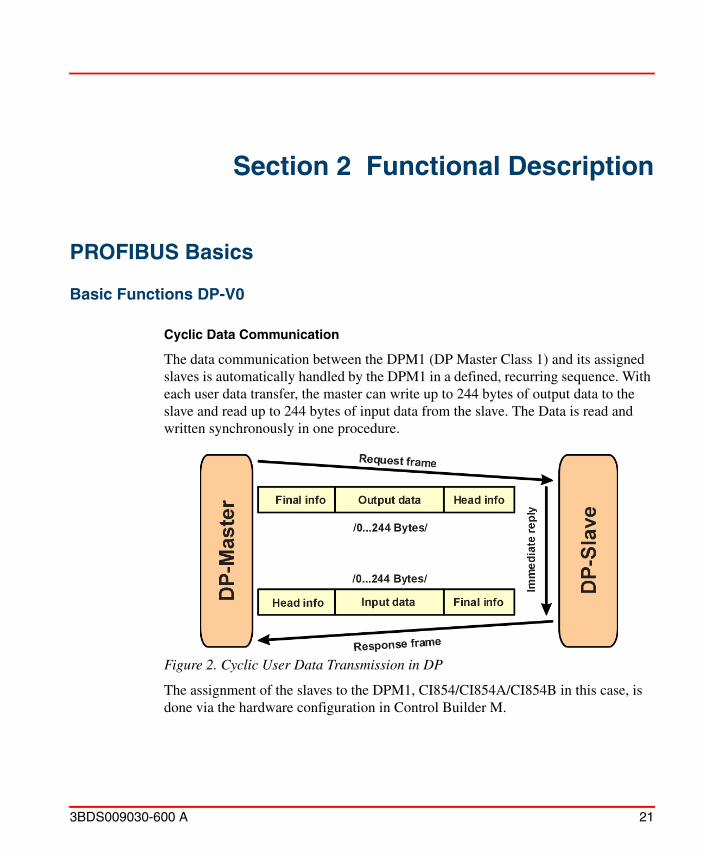
The data communication between the DPM1 (DP Master Class 1) and its assigned slaves is automatically handled by the DPM1 in a defined, recurring sequence. With each user data transfer, the master can write up to 244 bytes of output data to the slave and read up to 244 bytes of input data from the slave. The Data is read and written synchronously in one procedure.
Figure 2. Cyclic User Data Transmission in DP
The assignment of the slaves to the DPM1, CI854/CI854A/CI854B in this case, is done via the hardware configuration in Control Builder M.
Basic Functions DP-V0 Section 2 Functional Description
22 3BDS009030-600 A
The data communication between the DPM1 and the slaves is divided into three phases: parameterization, configuration and data transfer. Before the master includes a DP slave in the data transfer phase, a check is run during the parameterization and configuration phase to ensure that the configured setpoint configuration matches the actual device configuration. During this check, the device type, format and length information and the number of inputs and outputs must also correspond. This provides you with reliable protection against parameterization errors.
Diagnostics
In addition to the cyclic data the PROFIBUS slave unit provides diagnostic data. With this diagnostic data the slave can indicate errors or warnings on the slave unit, the I/O-units or the I/O-channels. Some diagnostic data is generic and defined by the PNO. But most of the diagnostic data is manufacturer specific.
The following errors/warnings are examples for PROFIBUS diagnostics:
Channel related:– Wire break– Short circuit
Module related:– Wrong module type– Module missing
Slave related:– Power supply 2 error– Internal bus error
The CI854/CI854A/CI854B supports the operation of PROFIBUS DP-V0 diagnostics. The diagnostic data transferred from the slave to the master is mapped by the CI854/CI854A/CI854B to the unit status of the PROFIBUS slave unit or the related I/O-unit and is indicated as error or warning in the UnitStatus in Control Builder M for the specific unit.
Only that diagnostic data configured within the hardware definition file is operated by the system. The configuration includes
– Selection of diagnostic to be operated by the system.– Mapping of the diagnostic information within the diagnostic frame on
PROFIBUS to the specific hardware unit (slave or I/O unit).
Section 2 Functional Description Basic Functions DP-V0
3BDS009030-600 A 23
– Definition of the corresponding bit in the unit status for the specific diagnostic information. Use of device specific codes in ErrorsAndWarnings and ExtendedStatus.
– Definition if the diagnostic information shall be indicated as error or warning.
– Definition of the presented text within unit status and alarm/event for the specific diagnostic information.
– Definition if in addition an alarm or event shall be generated for the specific diagnostic information. If yes also the severity has to be defined.
For S800 I/O and S900 I/O the configuration for the diagnostics is already specified in the hardware definition files that are provided with the system. For other slaves the configuration for PROFIBUS diagnostics can be done via the DeviceImport Wizard. The Device Import Wizard provides a dialog to pick up the diagnostic data from the GSD-file and map it to the DeviceSpecific and ExtendedStatus bits of the HwStatus for the related slave unit or I/O-unit. The dialog also supports the configuration of alarms/events based on the diagnostic data. For more information please refer to the online help for the Device Import Wizard.
DP Master Class 1 (DPM1) and Class 2 (DPM2)
TheDP master class 1 is the master that is in cyclic data transmission with the assigned slaves. To get into the cyclic communication the DPM1 has to configure the slave before.
The DP master class 2 is used for engineering and configuration. It does not have cyclic data transmission with the slave devices. Normally a DPM2 is only connected temporarily to the bus. A DPM2 can have class 2 communication to the slave devices before the slaves are configured via DPM1 and cyclic communication is active.
The CI854/CI854A/CI854B is of type DP master class 1 (DPM1) and class 2 (DPM2).
Basic Functions DP-V0 Section 2 Functional Description
24 3BDS009030-600 A
System Behavior
For a DPM1 master the following operating states are defined:
Stop
No data communication between the DPM1 and the slaves.
Clear
The DPM1 reads the input information of the slaves and keeps the outputs of the slavs in a fail-safe state (“0” output).
Operate
The DPM1 is in the data transfer phase. In cyclic data communication, inputs are red from the slaves and output information written to the slaves.
The reaction of the system to a fault during the data transfer phase of the DPM1, for example a failure of a slave, is determined by the “Auto Clear Modus” defined via the BP flag configuration in the settings tab for CI854/CI854A/CI854B. If this parameter is enabled, the DPM1 switches the outputs of all assigned slaves to a fail-safe state the moment a slave is no longer ready for user data transmission. The DPM1 subsequently switches to the clear state. If this parameter is disabled, the DPM1 retains in the operate state even in the event of a fault and the user can control the reaction of the system. Please refer also to Table on page 54.
Sync and Freeze Mode
In addition to the normal cyclic communication between the DPM1 (DP Master Class 1) and the assigned slaves, a master can send the control commands sync and freeze via multicast to a group of slaves.
With the sync-command the addressed slaves will freeze the outputs in their current state. New output values received by the master will be stored while the output states remain unchanged. The stored output data are not sent to the outputs until the next sync command is received. The Sync mode is terminated with the “unsync” command.
In the same way, a freeze command causes the addressed slaves to enter freeze mode. In this mode, the states of the inputs are frozen at their current value. The

Section 2 Functional Description Basic Functions DP-V0
3BDS009030-600 A 25
input data are not updated again until the master sends the next freeze command. Freeze mode is terminated with the “unfreeze” command.
Monitoring the DP-V0 Communication
The cyclic communication between the DPM1 and the slaves is monitored by the master and the slaves itself.
If the CI854/CI854A/CI854B master unit detects a failure in the communication with a slave, it will indicate the corresponding slave as disturbed. If enabled, Auto Clear Modus will be activated. On CI854A/CI854B a special handling is implemented to support also redundancy for master and slave. In both cases the monitoring timings consider the failovers of master and slave.
On slave side the communication with the master is controlled via the watchdog. If no data communication with the master occurs within the watchdog control interval, the slave automatically switches its outputs to the fail-safe state.
Please refer also to Connection Error on page 77
Multi Master Systems
In a multi master system several masters are connected to one bus. They represent either independent subsystems, comprising one DPM1 (DP Master Class 1) and its assigned slaves, or additional configuration and diagnosis devices. The CI854/CI854A/CI854B master unit supports multi master systems.
The Control Builder M with the integrated PROFIBUS master calculation does not support multi master configurations. The calculation only covers one CI854/CI854A/CI854B with its assigned slaves. If you connect several CI854/CI854A/CI854B or additional configuration devices to the same bus you have to adapt the bus settings manually. But only the TTR has to be adapted. An overall TTR has to be calculated as the sum of all individual TTR for the CI854/CI854A/CI854B master units connected to the same PROFIBUS. The resulting TTR has to be manually configured for all connected CI854/CI854A/CI854B master units.
The CI854/CI854A/CI854B does not support sync and freeze mode.
Version DP-V1 Section 2 Functional Description
26 3BDS009030-600 A
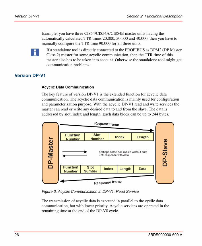
Example: you have three CI854/CI854A/CI854B master units having the automatically calculated TTR times 20.000, 30.000 and 40.000, then you have to manually configure the TTR time 90.000 for all three units.
Version DP-V1
Acyclic Data Communication
The key feature of version DP-V1 is the extended function for acyclic data communication. The acyclic data communication is mainly used for configuration and parameterization purpose. With the acyclic DP-V1 read and write services the master can read or write any desired data to and from the slave. The data is addressed by slot, index and length. Each data block can be up to 244 bytes.
The transmission of acyclic data is executed in parallel to the cyclic data communication, but with lower priority. Acyclic services are operated in the remaining time at the end of the DP-V0 cycle.
If a standalone tool is directly connected to the PROFIBUS as DPM2 (DP Master Class 2) master for some acyclic communication, then the TTR time of this master also has to be taken into account. Otherwise the standalone tool might get communication problems.
Figure 3. Acyclic Communication in DP-V1: Read Service
Section 2 Functional Description Redundancy
3BDS009030-600 A 27
The automatic master calculation for CI854/CI854A/CI854B ensures that the gap on PROFIBUS is big enough for some acyclic communication. If there is a need to increase the gap for some additional acyclic communication this can be done via the TTR time. Please refer also to Settings Tab on page 53.
Alarms and Status Messages
As a further function in DP-V1, the device specific diagnosis of the DP-V0 have been enhanced and divided into the categories alarms and status messages. As the major difference to the DP-V0 diagnosis, the alarms from the slave to the master are transferred via confirmed services.
RedundancyPROFIBUS and CI854A/CI854B have a high scalability for redundancy. Following options can be configured for redundancy:• PROFIBUS master unit CI854A/CI854B• PROFIBUS slave unit• PROFIBUS line.
Depending on your needs each type of redundancy can be configured independent of each other. Also mixed configurations are supported. You can configure for example a redundant PROFIBUS installation consisting of a redundant CI854A/CI854B master unit and redundant PROFIBUS lines and have connected redundant and non-redundant slave units in parallel.
A special mixture of redundancy is the so called combined slave and line redundancy. A slave provides two slave units supporting the PNO slave redundancy and each slave unit only provides one PROFIBUS interface. This is a one error tolerant solution. The slave unit will only have communication on one PROFIBUS line at a time and a single error on the PROFIBUS line will lead to a switchover of the slave units. But the big advantage of this solution are the reduced cost. Therefore it is a very popular solution. It is used for example for S800 I/O with CI840 and S900 I/O with CI920.
The CI854/CI854A/CI854B does not support the alarm and status message handling of DP-V1. Only DP-V0 diagnosis is supported.
Master Redundancy Section 2 Functional Description
28 3BDS009030-600 A
Master Redundancy
The CI854A/CI854B supports PROFIBUS master redundancy. Two CI854A/CI854B connected to one controller can be configured to work in a redundant configuration. The configuration for redundancy is done via configuring the CI854A/CI854B in the hardware tree of the Project Explorer. For configuration of redundancy please refer to Add Redundancy for Master Unit on page 46.
Primary and backup CI854A/CI854B need different node addresses on PROFIBUS. While the primary node address is configured via the settings in the hardware Configuration Editor the node address for the backup module is defined by the fixed offset -1 to the node address of the primary module. Therefore you cannot configure the node address 0 on PROFIBUS with CI854A/CI854B. This is reserved for redundancy.
During normal operation only the primary CI854A/CI854B has communication with the slave units. The backup unit is in hotstandby mode. It is configured by the controller and synchronized by the primary unit. If there is a failover because of for example a disturbed PROFIBUS communication, primary and backup module change the node addresses. During failover the former primary module will get reset.
After download and successful configuration the availability of the backup unit is monitored. This includes the balancing of current data and the communication links via PROFIBUS and CEX-Bus as well. In case of no error the DUAL LEDs on primary and backup unit will be lit. If the backup unit is not ready to takeover the DUAL LEDs will get off on both units. The error will be indicated in the unit status and a potential redundancy switchover will be inhibited in this case.
Reasons to perform a switchover are for example that the primary unit has lost the communication to all connected slaves “All slaves failed” because of for example a cabling problems or a “Fatal error” on the primary CI854A/CI854B itself was detected.
The PROFIBUS master redundancy is only supported by CI854A/CI854B and not CI854 and also the AC 800M controller type used must support redundancy.
If the CI854A/CI854B is configured for redundancy, the watchdog time will be increased automatically by 1000 ms. This allows CI854A/CI854B a switchover before the slaves will activate OSP (Output Set as Predetermined) control.
Section 2 Functional Description Slave Redundancy
3BDS009030-600 A 29
Slave Redundancy
CI854/CI854A/CI854B supports the PROFIBUS slave redundancy specified by the PROFIBUS User Organization (PNO). The specification can be found at http://www.profibus.com.
A redundant slave has two PROFIBUS interfaces, one for the primary and one for the backup slave. If line redundancy is used, one of the interfaces is connected to line A and the other to line B. If not, both interfaces are connected to the same PROFIBUS cable. The PROFIBUS address of the backup slave is always the address of the primary slave plus 64. The configuration in the Control Builder M ensures, that both addresses are available when the slave is set redundant. If a redundancy switchover of a slave occurs, also the PROFIBUS addresses are switched. That means, the primary slave always has the assigned address and the backup slave always has the address + 64 regardless of who is the primary and who is the backup. This kind of redundancy is called “flying redundancy”.
Only the primary slave can transfer process data and diagnostic information on the PROFIBUS. Therefore the status of the primary slave also contains the information of the backup slave. Please refer to the slave documentation for the details.
Although the backup slave has no active data transmission with the master the CI854/CI854A/CI854B is able to monitor the backup slave. The backup slave is available in the Livelist and if redundancy is configured the monitoring will be activated. If the backup slave fails, the information “Redundant slave does not exist” will be set in the ExtendedStatus of the primary slave.
To allow the slave a failover in case of an error the CI854/CI854A/CI854B has a special monitoring function. If the redundant slave gets disturbed the CI854/CI854A/CI854B waits for (2* watchdog time + 1) before connection down will be indicated for the slave. During this time the slave can perform a switchover and proceed with the normal data exchange without interrupting the communication.
CI854 module redundancy is supported for modules with the same module type. That is, if both the modules in the pair are CI854A or both are CI854B.
CI854 module redundancy is not supported, if one module is CI854A and the other is CI854B.
If the non-redundant slave is interrupted, the CI854/CI854A/CI854B waits for the watchdog time before the connection is down as indicated for the slave.
Line Redundancy Section 2 Functional Description
30 3BDS009030-600 A
Line Redundancy
CI854/CI854A/CI854B supports line redundancy for PROFIBUS DP. Therefore the two interfaces “PROFIBUS A” and “PROFIBUS B” are available on the baseplates TP854 of the modules. There is a Redundancy Link Module functionality implemented on the CI854/CI854A/CI854B that handles the sending and receiving of data on the PROFIBUS. Independent of any configuration the RLM sends data on both lines and receives data only via one line. Regarding the receiving of data the RLM checks if the slave sent data on both lines and if the data is valid. The first received valid data on line A or B will be picked up and operated. It is possible that the slave sends data on both lines in parallel or only on one line.
The monitoring of the line redundancy can be enabled or disabled. The default is disabled. The enabling is done via the parameter “Line redundancy” in the settings for CI854/CI854A/CI854B. If the line redundancy is enabled, a warning “No activity on PROFIBUS” will be indicated for the specific line in case of a failure, for example if there is a fault on the PROFIBUS cable.
Enable the monitoring of line redundancy, if– redundant slaves according to the PNO redundancy specification are used
and/or – non-redundant slaves provide a line redundant interface and/or – non-redundant slaves with only one PROFIBUS interface are connected to
the CI854/CI854A/CI854B with a RLM01.
The enabling of line redundancy does not affect the indication of the LEDs RxA and RxB on CI854/CI854A/CI854B.
In case of CI854A, the RxA/RxB LED is always ON as long as it is able to communicate on PROFIBUS network even with one of the configured slaves in Control Builder.
In case of CI854B, the status of the RxA/RxB LED depends on the number of slaves physically connected (not the configured slaves) on the PROFIBUS network.
RxA/RxB LEDs flickers for less number of physically connected slaves.
RxA/RxB LEDs is always ON for more number of physically connected slaves.
Section 2 Functional Description Status Handling
3BDS009030-600 A 31
Status Handling
Status Handling for DP-V1 Master Unit
Every status information for CI854/CI854A/CI854B in terms of hardware and software errors is indicated via the unit status. The unit status is used to present the status of the hardware unit in Control Builder M while it is in online mode. In addition alarms/events are generated based on the unit status (refer also to Alarms and Events on page 38). For special reasons also the access to the unit status via the controller application is supported.
Table 1 represent all device specific ErrorsAndWarnings and Table 2 represent ExtendedStatus defined for CI854/CI854A/CI854B.

Status Handling for DP-V1 Master Unit Section 2 Functional Description
32 3BDS009030-600 A
Table 1. Device Specific ErrorsAndWarnings for CI854/CI854A/CI854B
Bit Code Status TextStatus Type
Alarm/
EventSeverity Description
22 16#00400000 Wrong pair of CIs used for Redundancy
Warning Alarm Medium In CI854B Redundant configuration, if one
of the CI854B module is hot swapped with CI854A, Device Specific Error 10 ('Wrong pairs of CIs used for redundancy') message in unit status appears and remains until it is replaced back with CI854B module.
23 16#00800000 Hardware watchdog on CI854/CI854A/CI854B expired
Error Alarm Medium The hardware watchdog on the primary CI854/CI854A/CI854B was not triggered by the CI854/CI854A/CI854B firmware within the timeout.
24 16#01000000 Error in PROFIBUS master configuration
Error Alarm Medium A configuration error has been detected on the primary unit.
25 16#02000000 PROFIBUS com. failure between Primary and Backup
Warning Alarm Medium The PROFIBUS connection between primary and backup unit failed.

Section 2 Functional Description Status Handling for DP-V1 Master Unit
3BDS009030-600 A 33
26 16#04000000 Communication memory obtained too long
Warning Event High Overload of the communication memory access. There is too much access from the application tasks to the PROFIBUS I/O-data in the shared memory on the CI854/CI854A/CI854B so that the CI854/CI854A/CI854B cannot update the memory in time.
27 16#08000000 Duplicate address Warning Alarm Medium Two or more PROFIBUS nodes have the same address.
28 16#10000000 No activity on PROFIBUS line A
Warning Alarm Medium If line redundancy is enabled, this warning reflects the state of the RxA LED of the primary unit.
29 16#20000000 No activity on PROFIBUS line B
Warning Alarm Medium If line redundancy is enabled, this warning reflects the state of the RxB LED of the primary unit.
30 16#40000000 Hardware fail of CI854 (A)
Error Alarm High A hardware failure has been detected on the primary unit, for example RAM failure.
31 16#80000000 Firmware needs to be reloaded
Error Alarm Medium The primary unit does not contain a valid firmware.
Table 1. Device Specific ErrorsAndWarnings for CI854/CI854A/CI854B (Continued)
Bit Code Status TextStatus Type
Alarm/
EventSeverity Description
Status Handling for DP-V1 Master Unit Section 2 Functional Description
34 3BDS009030-600 A
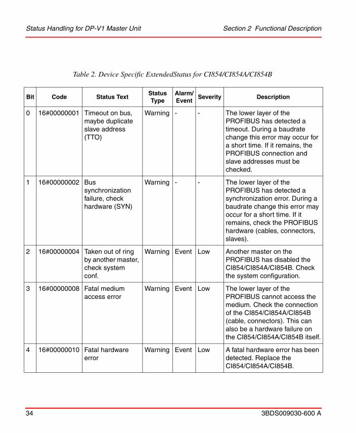
Table 2. Device Specific ExtendedStatus for CI854/CI854A/CI854B
Bit Code Status TextStatus Type
Alarm/ Event
Severity Description
0 16#00000001 Timeout on bus, maybe duplicate slave address (TTO)
Warning - - The lower layer of the PROFIBUS has detected a timeout. During a baudrate change this error may occur for a short time. If it remains, the PROFIBUS connection and slave addresses must be checked.
1 16#00000002 Bus synchronization failure, check hardware (SYN)
Warning - - The lower layer of the PROFIBUS has detected a synchronization error. During a baudrate change this error may occur for a short time. If it remains, check the PROFIBUS hardware (cables, connectors, slaves).
2 16#00000004 Taken out of ring by another master, check system conf.
Warning Event Low Another master on the PROFIBUS has disabled the CI854/CI854A/CI854B. Check the system configuration.
3 16#00000008 Fatal medium access error
Warning Event Low The lower layer of the PROFIBUS cannot access the medium. Check the connection of the CI854/CI854A/CI854B (cable, connectors). This can also be a hardware failure on the CI854/CI854A/CI854B itself.
4 16#00000010 Fatal hardware error
Warning Event Low A fatal hardware error has been detected. Replace the CI854/CI854A/CI854B.

Section 2 Functional Description Status Handling for DP-V1 Master Unit
3BDS009030-600 A 35
5 16#00000020 All slaves failed Warning Alarm Medium Check the PROFIBUS connections (cable, connector at the CI854/CI854A/CI854B). The reason can also be a hardware error of the CI854/CI854A/CI854B. If the CI854A/CI854B is used redundant, this error leads to a redundancy switchover.
In case of CI854A, All slaves failed is displayed if the master
CI854 is not able to reach any of the slaves configured.
In case of CI854B, All slaves failed will be displayed if the
PROFIBUS connector is disconnected from the master CI548 end. In case the connector is not disconnected, but the master is not able to reach to the slaves the slaves will be displayed with connection down status.
6 16#00000040 Hardware configuration error on backup
Warning Event Low A configuration error has been detected for the backup unit.
7 16#00000080 Backup device not found
Warning Event Low The backup unit was not found on the CEX-Bus.
8 16#00000100 I/O configuration error on backup
Warning Alarm Medium The backup CI854A/CI854B has detected a configuration error for a slave unit.
Table 2. Device Specific ExtendedStatus for CI854/CI854A/CI854B (Continued)
Bit Code Status TextStatus Type
Alarm/ Event
Severity Description

Status Handling for DP-V1 Master Unit Section 2 Functional Description
36 3BDS009030-600 A
9 16#00000200 I/O connection error on backup
Warning Alarm Medium The backup CI854A/CI854B has detected a configuration error for a slave unit.
10 16#00000400 Hardware watchdog on Backup CI854(A) expired
Warning Event Low The hardware watchdog on the backup CI854/CI854A/CI854B was not triggered by the CI854/CI854A/CI854B firmware within the timeout.
11 16#00000800 Error in PROFIBUS master configuration of Backup
Warning Event Low A configuration error has been detected on the backup unit.
12 16#00001000 No activity on PROFIBUS line A of Backup
Warning Alarm Medium If line redundancy is enabled, this warning reflects the state of the RxA LED of the backup unit.
13 16#00002000 No activity on PROFIBUS line B of Backup
Warning Alarm Medium If line redundancy is enabled, this warning reflects the state of the RxB LED of the backup unit.
14 16#00004000 Hardware fail of CI854A Backup
Warning Alarm Medium A hardware failure has been detected on the backup unit, for example RAM failure.
15 16#00008000 Firmware needs to be reloaded on Backup
Warning Alarm Medium The backup unit does not contain a valid firmware.
16 16#00010000 CEX-Bus com. failure between Primary and Backup
Warning Alarm Medium The CEX-Bus connection between primary and backup unit failed.
Table 2. Device Specific ExtendedStatus for CI854/CI854A/CI854B (Continued)
Bit Code Status TextStatus Type
Alarm/ Event
Severity Description

Section 2 Functional Description Status Handling for Slave Units
3BDS009030-600 A 37
Status Handling for Slave Units
CI854/CI854A/CI854B also handles status information for the connected slave units. If there is a failure on the PROFIBUS slave, an indication for the FCI or the specific I/O-unit will appear.
There are several reasons to let the CI854/CI854A/CI854B indicate some status information for the slave unit:
• No cyclic communication to the slave:Connection down will be indicated for the disturbed slave unit.
17 16#00020000 Fatal error on Primary detected
Error Alarm High A general error has been detected on the primary unit and the CI854/CI854A/CI854B stops the normal operation. If the CI854A is used redundant, this error leads to a redundancy switchover.
18 16#00040000 Fatal error on Backup detected
Warning Alarm Medium A general error has been detected on the backup unit and the CI854/CI854A/CI854B stops the normal operation. This error prohibits a redundancy switchover.
19 16#00080000 Master state has changed to CLEAR due to disturbed slave
Warning Alarm Medium
20 16#00100000 Master state disturbed bus error
Warning Alarm Medium
21 16#00200000 Master state protocol error
Warning Alarm Medium
Table 2. Device Specific ExtendedStatus for CI854/CI854A/CI854B (Continued)
Bit Code Status TextStatus Type
Alarm/ Event
Severity Description

Alarms and Events Section 2 Functional Description
38 3BDS009030-600 A
• Slave has active standard diagnosis: The slave indicates for example “Parameter data fault” or “Configuration data fault”. This errors will be indicated without any special configuration.
• Slave has active extended diagnosis: This is also called PROFIBUS Diagnostics. Depending on the configuration the diagnostic information is indicated for the FCI (Fieldbus Communication Interface) or the related I/O-unit. Please refer also to Diagnostics on page 22.
• A monitoring function has detected a failure:The CI854/CI854A/CI854B for example has detected a configuration error during download or the backup slave is not present on the PROFIBUS.
Alarms and Events
PROFIBUS DP-V1 uses the general alarm and event handling provided with the system. Alarms and events are generated only via the status interface. The CI854/CI854A/CI854B influences the generation of alarms/events by setting/resetting the individual status bits. For every status bit in ErrorsAndWarnings and ExtendedStatus a fixed configuration information is available that defines if a change of a status bit shall generate an alarm or event. The generated alarms/events are of the type system alarm or system event. With the generation of the alarm/event the status interface also adds the severity and the time stamp.
Hot SwapCI854/CI854A/CI854B supports hot swap. It can be replaced without any disturbance to other units connected to the CEX-Bus. After hot removal and subsequent insertion, the unit is configured automatically.
After hot insert, the boot up time of CI854B is more compared to the boot up time of CI854/CI854A. It takes about 25 seconds for the CI854B to boot whereas CI854/CI854A boots within 5-6 seconds.
Controller versions 6.0 and above supports CI854B module.
CI854/CI854A module can be replaced with CI854B only in system versions 6.0 and above.

Section 2 Functional Description Replacement of CI854/CI854A/CI854B in Non Redundant
3BDS009030-600 A 39
Replacement of CI modules in Redundant and Non-redundant configuration is explained in the following topics:
Replacement of CI854/CI854A/CI854B in Non Redundant Configuration
A non redundant CI854/CI854A/CI854B can be replaced with another CI854/ CI854A/CI854B module by hot removing the existing module and hot inserting the new module in its position.
Replacement of CI854/CI854A/CI854B in Redundant Configuration
Replacing CI854A with Same Module Type
For a redundant CI854A configuration,
– first hot remove the primary CI854A. This initiates a module switch-over.
– then, hot insert a new CI854A in its place.
– continue replacing the other CI854A with a new CI854A.
Replacing CI854B with Same Module Type
For a redundant CI854B configuration,
– first hot remove the primary CI854B. This initiates a module switch-over.
– then, hot insert a new CI854B in its place.
– continue replacing the other CI854B with a new CI854B.
Replacing CI854A with CI854B
For a redundant CI854A configuration,
– first hot remove the primary CI854A. This initiates a module switch-over.
– then, hot insert the CI854B.
Both the above replacements can be done online as the replacements are with the same module type.

Hot Configuration in Run (HCIR) Section 2 Functional Description
40 3BDS009030-600 A
– at this stage module redundancy does not work, as one of the module is CI854A and the other CI854B.
– continue replacing the other CI854A with CI854B.
Replacing CI854B with CI854A
For a redundant CI854B configuration,
– first hot remove the primary CI854B. This initiates a module switch-over.
– then, hot insert the CI854A.
– at this stage module redundancy does not work, as one of the module is CI854B and the other CI854A.
– continue replacing the other CI854B with CI854A.
Hot Configuration in Run (HCIR)Hot configuration in run a slave can be configured online without initializing the PROFIBUS communication. The new or changed configuration is downloaded to the slave while the cyclic communication keeps active.
If a slave supports HCIR, then I/O-units can be added or deleted online. During reconfiguration the cyclic data transmission between CI854/CI854A/CI854B and the slave is stopped. The CI854/CI854A/CI854B keeps the input values and the slave the output values. After completing the reconfiguration, the cyclic data transmission will proceed based on the new configuration data.
The reconfiguration is monitored by the CI854/CI854A/CI854B with the HCIR timeout. By starting the reconfiguration the HCIR timeout is sent via a SetPrm telegram to the slave. This indicates the slave to increase the watchdog timeout to the value defined by the HCIR timeout until the reconfiguration is finished. The timeout for HCIR is defined on CI854/CI854A/CI854B by:
HCIRtimeout = 10 x TTR / (bit/sec) + 300 ms.
Both the above replacements cannot be done online without affecting the process, as the replacements are with different module type.

Section 2 Functional Description Hot Configuration in Run (HCIR)
3BDS009030-600 A 41
Configuration through HCIR is only possible for slaves that have implemented this feature such as S800 I/O and S900 I/O. To activate the HCIR sequence, a special entry in the hardware definition file is necessary. For slaves imported through the Device Import Wizard, this parameter is automatically set if the setting is available in the GSD file.

Hot Configuration in Run (HCIR) Section 2 Functional Description
42 3BDS009030-600 A
3BDS009030-600 A 43
Section 3 Configuration
Hardware LibraryTo configure hardware types for PROFIBUS master and slave units hardware libraries are used. How to handle hardware libraries, refer System 800xA Control AC 800M Configuration (3BSE035980*) and Compact Control Builder AC 800M Configuration (3BSE040935*) Manual.
Insert PROFIBUS Master UnitTo insert a new CI854/CI854A/CI854B PROFIBUS DP-V1 master unit proceed as described.
1. Right-click on the controller you want to insert the CI854/CI854A/CI854B and select Insert Unit. The Insert Unit dialog pops up.
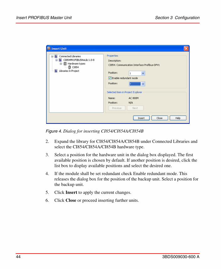
Figure 4. Dialog for inserting CI854/CI854A/CI854B
Insert PROFIBUS Master Unit Section 3 Configuration
44 3BDS009030-600 A
2. Expand the library for CI854/CI854A/CI854B under Connected Libraries and select the CI854/CI854A/CI854B hardware type.
3. Select a position for the hardware unit in the dialog box displayed. The first available position is chosen by default. If another position is desired, click the list box to display available positions and select the desired one.
4. If the module shall be set redundant check Enable redundant mode. This releases the dialog box for the position of the backup unit. Select a position for the backup unit.
5. Click Insert to apply the current changes.
6. Click Close or proceed inserting further units.
Section 3 Configuration Insert PROFIBUS Master Unit
3BDS009030-600 A 45
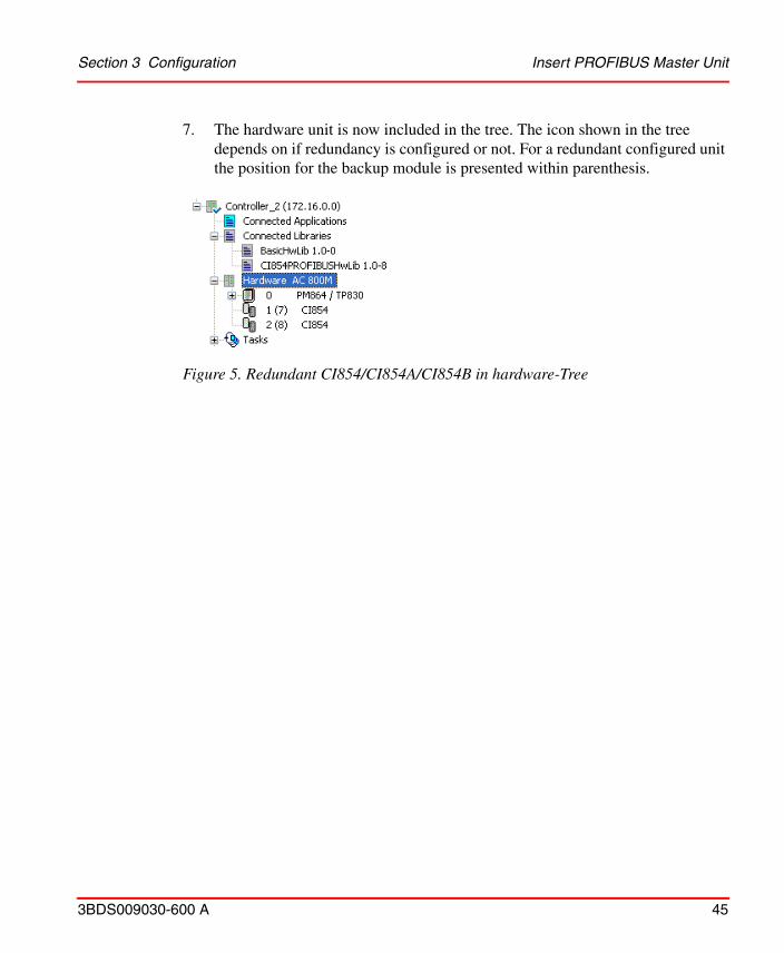
7. The hardware unit is now included in the tree. The icon shown in the tree depends on if redundancy is configured or not. For a redundant configured unit the position for the backup module is presented within parenthesis.
Figure 5. Redundant CI854/CI854A/CI854B in hardware-Tree

Add Redundancy for Master Unit Section 3 Configuration
46 3BDS009030-600 A
Add Redundancy for Master UnitIf the CI854A/CI854B is already configured and running in single mode you can add redundancy.
1. Right-click on the unit you want to add the redundancy and select Redundancy > Add Redundant Unit.
2. Select a position for the backup unit in the dialog box displayed. The first available position is chosen by default. If another position is desired, click the list box to display available positions and select the desired one.
Figure 6. CEX-Bus Position for backup CI854A/CI854B
3. The icon changes to the redundancy icon and the text is updated with backup position within parenthesis (see Figure 5: Redundant CI854/CI854A/CI854B in hardware-Tree).
The inserted backup unit is called unit B. Unit B is fixed related to the configured position. Unit B starts as backup but acts as primary after failover.
Section 3 Configuration Delete Redundancy for Master Unit
3BDS009030-600 A 47
Delete Redundancy for Master UnitIf the CI854A/CI854B is already configured and running in redundant mode you can delete redundancy.
1. Right-click on the CI854A/CI854B you want to delete redundancy for and select Redundancy > Delete Backup.
2. The icon changes to the single icon and the position for the backup is deleted in the text.
In the offline mode of Control Builder M unit B is always presented as the backup unit independent of the current state. Therefore always unit B will be deleted as backup. If you download and go online a failover may be performed by CI854A/CI854B if unit B acts as primary. Unit A gets primary and afterwards unit B will get deleted.
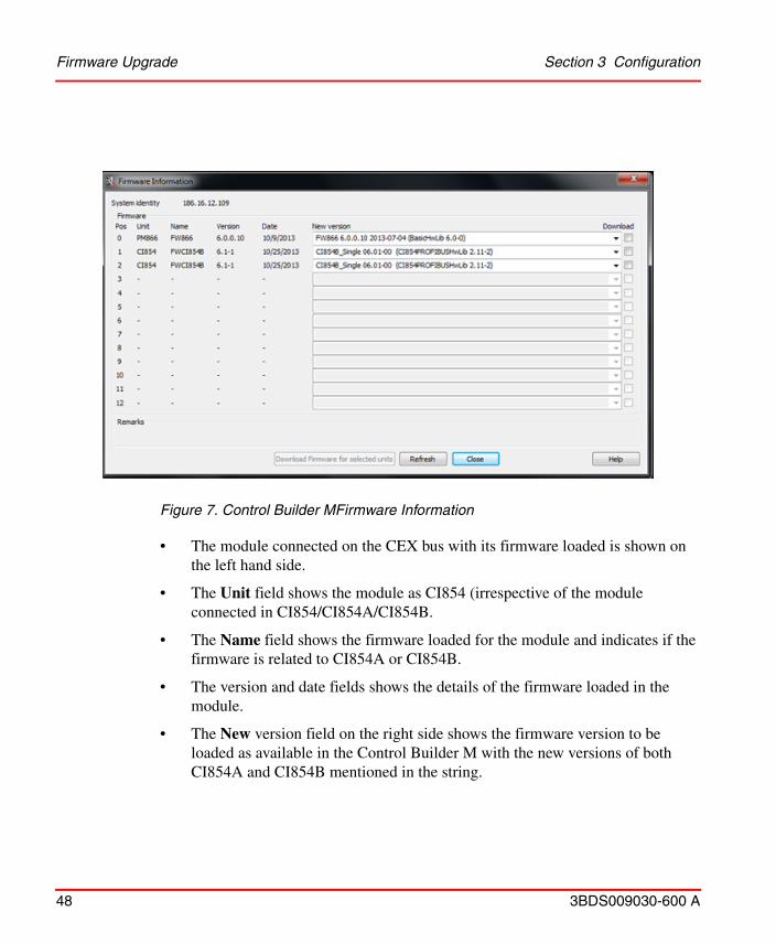
Firmware UpgradeFirmware upgrade for the CI854/CI854A/CI854B modules is performed by right clicking the controller in Controller Builder > Remote System > Show Firmware Information (see Figure 7).
CI854B hardware is not supported in versions prior to System Version 6.0. For versions prior to SV 6.0, CI854B module will be displayed in the firmware window, however, you cannot perform firmware upgrade as it is not supported.
Firmware Upgrade Section 3 Configuration
48 3BDS009030-600 A
• The module connected on the CEX bus with its firmware loaded is shown on
the left hand side.
• The Unit field shows the module as CI854 (irrespective of the module connected in CI854/CI854A/CI854B.
• The Name field shows the firmware loaded for the module and indicates if the firmware is related to CI854A or CI854B.
• The version and date fields shows the details of the firmware loaded in the module.
• The New version field on the right side shows the firmware version to be loaded as available in the Control Builder M with the new versions of both CI854A and CI854B mentioned in the string.
Figure 7. Control Builder MFirmware Information
Section 3 Configuration Configure the PROFIBUS Master Unit
3BDS009030-600 A 49
• When the user selects this module for firmware upgrade, based on the module connected, the corresponding firmware is loaded.
The CI854B is restarted twice during the firmware upgrade. The first reset is after the CI854B firmware is loaded and the second reset is after the new stack is loaded. CI85B is reset only once, if the stack does not require an upgrade.
The CI854 PROFIBUS Hardware Library consists of single CI854 Hardware module type and this module type is same for both CI854A and CI854Bfirmware.
Configure the PROFIBUS Master Unit
Hardware Editor
Open the hardware editor via double-click on the hardware unit or choose Editor from the CI854 context menu. The hardware editor contains the following tabs: Settings, Connections and Unit Status.

Hardware Editor Section 3 Configuration
50 3BDS009030-600 A
Settings Tab
Figure 8 shows the list of default parameter values defined for CI854/CI854A/CI854B.
These parameters are used to set up CI854/CI854A/CI854B. Normally, most of the parameters need not be changed. Parameters marked with a * will be calculated
Figure 8. Settings for CI854/CI854A/CI854B

Section 3 Configuration Hardware Editor
3BDS009030-600 A 51
(during download) by the Control Builder, but may need to be adjusted due to special slaves, repeaters, or segment couplers used.
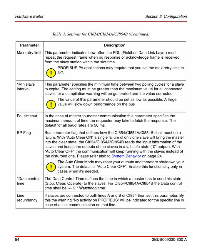
Table 3. Settings for CI854/CI854A/CI854B
Parameter Description
Node address This is the PROFIBUS address of the master which can be in the range 1-125. This address must differ from all other slave addresses, otherwise a compilation error is generated. Slaves are assigned their addresses according to the device numbering in the configuration. With multi-master systems ensure that there is no addressing conflict with the other masters and their slaves.
Baudrate Supported baudrates are 9.6; 19.2; 93.75; 187.5; 500; 1500; 3000; 6000 and 12000 kbit/s. Not support are the baud rates 31.25 and 45.45 kbit/s. The default value is 1.5 Mbit/s. Higher values require careful consideration of correct cable installation. All slave devices must support baud rate setting. Some slaves require a manual reset after change of the baud rate. A compilation warning occurs if a slave does not support the selected baud rate. In this case the next lower supported baud rate will be selected automatically. If no one can be found, a compilation error will be generated. Changing the baud rate may also require changing of other bus parameters to ensure successful communication. The automatic calculation will determine the right settings. Default values of parameters at different baud rates can be found in Table 4.
*Watchdog time (TWD)
Each slave has a watchdog timer that is retriggered by requests from the master. If the watchdog time expires the slave outputs are set to the predetermined value. This control ensures a controlled predetermined value if there is a break in the master or the communication system. Set the watchdog time at least as long as the theoretical system reaction time (see Target Rotation Time, TTR, below). Watchdog time should be greater or equal than TTR * tbit * 10, where tbit = (1/baud rate[kbits/s]). For example, with TTR = 20000 tbit and baud rate = 9.6 kbit/s, the watchdog parameter should be greater than: 20000 * (1/9.6) * 10 = 2084 ms. For example, witch TTR = 20000 tbit and baud rate = 1.5 Mbit/s, the watchdog parameter should be greater than: 20000 * (1/1500) * 10 = 133 ms. The automatic calculation during the download prohibits a too short watchdog time and issues an appropriate warning or error message.

Hardware Editor Section 3 Configuration
52 3BDS009030-600 A
*Slot time The slot time is the maximum time a master must wait for a transaction response. It must always be greater than (>)MaxTsdr + TQUI + 11 + 2 + SafetyMargin (see below for MaxTsdr and TQUI) or a compilation warning will be generated and the value will be set to the smallest one allowed. Setting it too high may slow down the performance.
PROFIBUS PA may require long settings for the slot time.
*Min station delay (MinTsdr)
The period of time which elapses before the responder can send the response frame expressed in tbits. Slave implementation determines, however, the minimum response time. The default value is 11 tbits. Setting MinTsdr too high may slow down the performance. Settings below 11 will be overwritten with the defined minimum value 11 when closing the editor window.
*Max station delay (MaxTsdr)
The maximum time the slave is given to respond to a request message, expressed in tbits. At different baud rates it may have different values. The automatic calculation ensures that the value set in the master is higher or equal than the highest value for the connected slaves. If not, a warning or error message will be shown.
*Quiet time (TQUI)
The period of time a transmitting station must wait after the end of a frame before enabling its receiver. Its purpose is to take care of transmitter fall time after switching off the transmitter. It is significant when using self-controlled repeaters. The automatic calculation ensures that TQUI is less than MinTsdr or a compilation warning will be generated and the value will be set to the highest allowed value.
*Setup time The time between the occurrence of an interrupt request (for example, SYN timer expired) and the necessary reaction (for example, enabling the receiver). The value depends on the baud rate.
PROFIBUS PA applications may require longer times than the default values at the different baud rates.
Table 3. Settings for CI854/CI854A/CI854B (Continued)
Parameter Description

Section 3 Configuration Hardware Editor
3BDS009030-600 A 53
*Target rotation time (TTR)
The target rotation time is the anticipated time for one token rotation on the PROFIBUS network, including allowances for high- and low-priority transactions and GAP maintenance. For networks with one master it must be greater than the system reaction time.
The automatic calculation for the CI854/CI854A/CI854B ensures, that TTR is high enough for a single CI854 or a redundant CI854A/CI854B PROFIBUS master and all its slaves plus two acyclic communications used for toolrouting plus a safety margin according to the defined max retry limit.
The calculated value may be increased to allow more acyclic traffic, if necessary.If there are other masters on the bus, the calculated value has to be increased for the time these other masters need for their cyclic and acyclic communication. Refer to the configuration of these masters.
In a multi-master system all masters must use the same value for TTR.
GAP factor (GAP)
This parameter defines the number of token rotations between GAP maintenance cycles.
The current version of the CI854/CI854A/CI854B always uses a value of 1 independent of the value entered here.
Highest station address (HSA)
This parameter defines the highest station address on the PROFIBUS. Set the parameter to at least the highest number of node addresses configured for all masters and slaves present on the bus.
Redundant slaves may use it for checks of the backup slave. Do not set it below the highest used (redundant) slave address.
Optical link modules uses this parameter to manage the redundancy functionality. The HSA has to be at least one greater than the highest number of node addresses for masters and slaves present on the bus.
It is highly recommended not to change the default of 126.
Table 3. Settings for CI854/CI854A/CI854B (Continued)
Parameter Description
Hardware Editor Section 3 Configuration
54 3BDS009030-600 A
Max retry limit This parameter indicates how often the FDL (Fieldbus Data Link Layer) must repeat the request frame when no response or acknowledge frame is received from the slave station within the slot time.
PROFIBUS PA applications may require that you set the max retry limit to 3-7.
*Min slave interval
This parameter specifies the minimum time between two polling cycles for a slave to expire. The setting must be greater than the maximum value for all connected slaves, or a compilation warning will be generated and the value corrected.
The value of this parameter should be set as low as possible. A large value will slow down performance on the bus
Poll timeout In the case of master-to-master communication this parameter specifies the maximum amount of time the requester may take to fetch the response. The default for all baud rates are 50 ms.
BP Flag Bus parameter flag that defines how the CI854/CI854A/CI854B shall react on a failure. With “Auto Clear ON” a single failure of only one slave will bring the master into the clear state: the CI854/CI854A/CI854B reads the input information of the slaves and keeps the outputs of the slaves in a fail-safe state (“0” output). With “Auto Clear OFF” the communication will keep running with the slaves instead of the disturbed one. Please refer also to System Behavior on page 24.
The Auto Clear Mode may reset your outputs and therefore shutdown your system. The default is “Auto Clear OFF”. Enable this functionality only in cases when it’s needed.
*Data control time
The Data Control Time defines the time in which a master has to send his state (Stop, Clear, Operate) to the slaves. For CI854/CI854A/CI854B the Data control time shall be >= 2 * Watchdog time.
Line redundancy
If slaves are connected to both lines A and B of CI854 then set this parameter. By this the warning “No activity on PROFIBUS” will be indicated for the specific line in case of a lost communication on that line.
Table 3. Settings for CI854/CI854A/CI854B (Continued)
Parameter Description

Section 3 Configuration Automatic Calculation of PROFIBUS Master Parameter
3BDS009030-600 A 55
Connection Tab
For CI854/CI854A/CI854B a connection to the UnitStatus can be configured. For more information refer to Control Builder M online help.
Unit Status Tab
For information on the Unit Status tab, refer to Control Builder M online help.
Automatic Calculation of PROFIBUS Master Parameter
The easiest way to define the bus parameters is to let the system calculate them. You only have to set:
– the node address, – the baudrate and – the line redundancy mode
to the required values. All other parameters don’t need to be changed. The Parameters marked with a * in Table 3 are calculated automatically during download depending on the actual configuration for the slave units.
Delta TTR Increases automatically the calculated TTR time (see Target Rotation Time (TTR), above).
A change for Delta TTR is only needed if there is a high load of acyclic DP-V1 communication on the PROFIBUS used for toolrouting.
Calculation Method
With this parameter you can define if you want to make a calculation based on the actual entered values (Actual value based) or if the calculation shall determine the minimal possible values to achieve the fastest cycle time on PROFIBUS (Minimum value based).
Table 3. Settings for CI854/CI854A/CI854B (Continued)
Parameter Description
Automatic Calculation of PROFIBUS Master Parameter Section 3 Configuration
56 3BDS009030-600 A
The automatic calculation ensures that all calculated parameters will be on the safe side. This means also manual changes have to be considered. Therefore no changes of the actual settings in direction to faster but insecure values takes place.
To get the optimized values for the PROFIBUS master parameters set the parameter Calculation method to Minimum value based. The automatic calculation will now recalculate all parameters. The result is the fastest possible cycle time you can reach for the configured slaves.
If you have devices that need special settings then first proceed as described above. In a second run do the manual adjustments to the specific parameters, switch the parameter Calculation method to Actual value based and repeat automatic calculation.
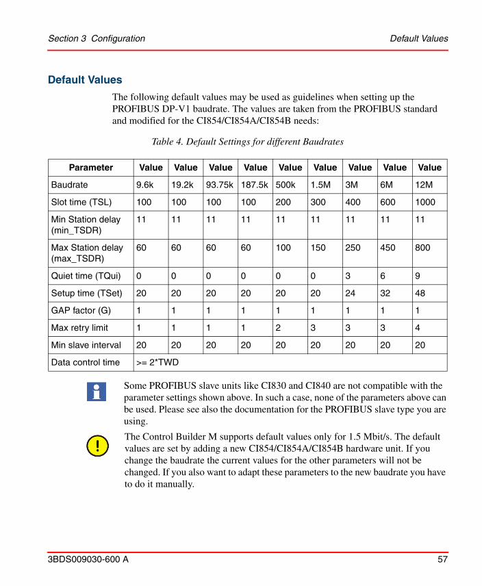
Section 3 Configuration Default Values
3BDS009030-600 A 57
Default Values
The following default values may be used as guidelines when setting up the PROFIBUS DP-V1 baudrate. The values are taken from the PROFIBUS standard and modified for the CI854/CI854A/CI854B needs:
Table 4. Default Settings for different Baudrates
Parameter Value Value Value Value Value Value Value Value Value
Baudrate 9.6k 19.2k 93.75k 187.5k 500k 1.5M 3M 6M 12M
Slot time (TSL) 100 100 100 100 200 300 400 600 1000
Min Station delay (min_TSDR)
11 11 11 11 11 11 11 11 11
Max Station delay (max_TSDR)
60 60 60 60 100 150 250 450 800
Quiet time (TQui) 0 0 0 0 0 0 3 6 9
Setup time (TSet) 20 20 20 20 20 20 24 32 48
GAP factor (G) 1 1 1 1 1 1 1 1 1
Max retry limit 1 1 1 1 2 3 3 3 4
Min slave interval 20 20 20 20 20 20 20 20 20
Data control time >= 2*TWD
Some PROFIBUS slave units like CI830 and CI840 are not compatible with the parameter settings shown above. In such a case, none of the parameters above can be used. Please see also the documentation for the PROFIBUS slave type you are using.
The Control Builder M supports default values only for 1.5 Mbit/s. The default values are set by adding a new CI854/CI854A/CI854B hardware unit. If you change the baudrate the current values for the other parameters will not be changed. If you also want to adapt these parameters to the new baudrate you have to do it manually.
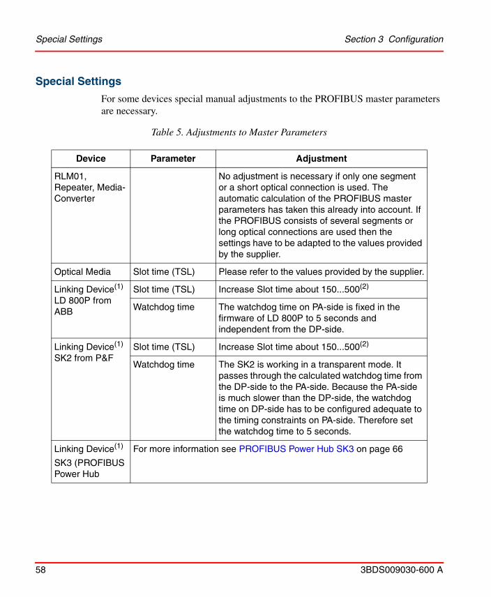
Special Settings Section 3 Configuration
58 3BDS009030-600 A
Special Settings
For some devices special manual adjustments to the PROFIBUS master parameters are necessary.
Table 5. Adjustments to Master Parameters
Device Parameter Adjustment
RLM01, Repeater, Media-Converter
No adjustment is necessary if only one segment or a short optical connection is used. The automatic calculation of the PROFIBUS master parameters has taken this already into account. If the PROFIBUS consists of several segments or long optical connections are used then the settings have to be adapted to the values provided by the supplier.
Optical Media Slot time (TSL) Please refer to the values provided by the supplier.
Linking Device(1) LD 800P from ABB
Slot time (TSL) Increase Slot time about 150...500(2)
Watchdog time The watchdog time on PA-side is fixed in the firmware of LD 800P to 5 seconds and independent from the DP-side.
Linking Device(1)SK2 from P&F
Slot time (TSL) Increase Slot time about 150...500(2)
Watchdog time The SK2 is working in a transparent mode. It passes through the calculated watchdog time from the DP-side to the PA-side. Because the PA-side is much slower than the DP-side, the watchdog time on DP-side has to be configured adequate to the timing constraints on PA-side. Therefore set the watchdog time to 5 seconds.
Linking Device(1)
SK3 (PROFIBUS Power Hub
For more information see PROFIBUS Power Hub SK3 on page 66

Section 3 Configuration Insert a Slave Unit
3BDS009030-600 A 59
Insert a Slave UnitTo add a new PROFIBUS DP slave unit proceed as described.
Linking Device SK1 from P&F
Baudrate 93.75k
Slot time (TSL) 4095 / 7192(3)
Min Station delay (min_TSDR)
22
Max Station delay (max_TSDR)
1000
Quiet time (TQui) 0
Setup time (TSet) 150
GAP factor 10
(1) To get the 12 Mbit/s supported by the LD 800P, SK2 or SK3 enabled, an adaptation of the timing parameters for the slave device is necessary. This is automatically done by the Device Import Wizard during conversion of the GSD file to HWD file. If object types of the Device Library are used, they already have the timing parameters adapted for LD 800P, SK2 and SK3.
(2) Increase the slot time if there is high traffic for acyclic DP-V1 communication.(3) Use this value if the total of input and output data for one PA device exceeds 253 bytes.
Table 6.
If necessary the watchdog time for LD 800P, SK2, and SK3 can be decreased. The exact value can be calculated based on the I/O data length, the number of PA-devices, length of PA-segments etc. For more information refer to the User Instructions for LD 800P, SK2, and SK3.
Table 5. Adjustments to Master Parameters
Device Parameter Adjustment
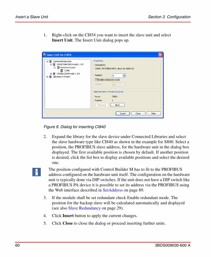
Insert a Slave Unit Section 3 Configuration
60 3BDS009030-600 A
1. Right-click on the CI854 you want to insert the slave unit and select Insert Unit. The Insert Unit dialog pops up.
Figure 9. Dialog for inserting CI840
2. Expand the library for the slave device under Connected Libraries and select the slave hardware type like CI840 as shown in the example for S800. Select a position, the PROFIBUS slave address, for the hardware unit in the dialog box displayed. The first available position is chosen by default. If another position is desired, click the list box to display available positions and select the desired one.
The position configured with Control Builder M has to fit to the PROFIBUS address configured on the hardware unit itself. The configuration on the hardware unit is typically done via DIP switches. If the unit does not have a DIP switch like a PROFIBUS PA device it is possible to set its address via the PROFIBUS using the Web interface described in SetAddress on page 89.
3. If the module shall be set redundant check Enable redundant mode. The position for the backup slave will be calculated automatically and displayed (see also Slave Redundancy on page 29).
4. Click Insert button to apply the current changes.
5. Click Close to close the dialog or proceed inserting further units.
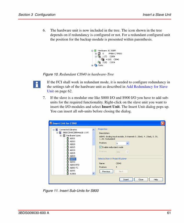
Section 3 Configuration Insert a Slave Unit
3BDS009030-600 A 61
6. The hardware unit is now included in the tree. The icon shown in the tree depends on if redundancy is configured or not. For a redundant configured unit the position for the backup module is presented within parenthesis.
Figure 10. Redundant CI840 in hardware-Tree
If the FCI shall work in redundant mode, it is needed to configure redundancy in the settings tab of the hardware unit as described in Add Redundancy for Slave Unit on page 62.
7. If the slave is a modular one like S800 I/O and S900 I/O you have to add sub-units for the required functionality. Right-click on the slave unit you want to insert the I/O-modules and select Insert Unit. The Insert Unit dialog pops up. You can insert all sub-units before closing the dialog.
Figure 11. Insert Sub-Units for S800

Figure 12. Redundant PROFIBUS with S800 I/O and S900 I/O in hardware Tree
Add Redundancy for Slave Unit Section 3 Configuration
62 3BDS009030-600 A
Add Redundancy for Slave Unit
If the slave is already configured and running in single mode you can add redundancy.
1. Right-click on the unit you want to add the redundancy and select Redundancy > Add Redundant Unit.
2. The icon changes to the redundancy icon and the text is updated with backup position within parenthesis (see Figure 10: Redundant CI840 in hardware-Tree). The position for the backup unit will be calculated automatically (see also Slave Redundancy on page 29). The position of the backup module is given by the fixed offset of +64 to the position of the primary module.
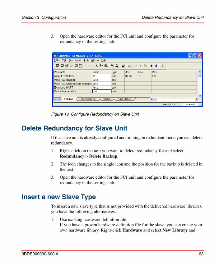
Section 3 Configuration Delete Redundancy for Slave Unit
3BDS009030-600 A 63
3. Open the hardware editor for the FCI unit and configure the parameter for redundancy in the settings tab.
Figure 13. Configure Redundancy on Slave Unit
Delete Redundancy for Slave UnitIf the slave unit is already configured and running in redundant mode you can delete redundancy.
1. Right-click on the unit you want to delete redundancy for and select Redundancy > Delete Backup.
2. The icon changes to the single icon and the position for the backup is deleted in the text.
3. Open the hardware editor for the FCI unit and configure the parameter for redundancy in the settings tab.
Insert a new Slave TypeTo insert a new slave type that is not provided with the delivered hardware libraries, you have the following alternatives:
1. Use existing hardware definition fileIf you have a proven hardware definition file for the slave, you can create your own hardware library. Right-click Hardware and select New Library and
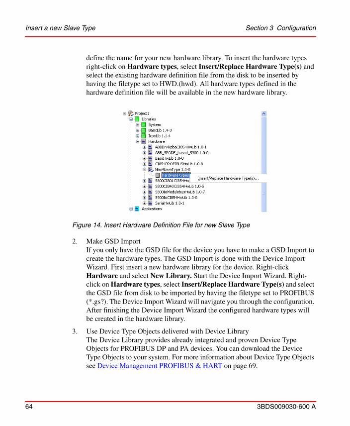
Insert a new Slave Type Section 3 Configuration
64 3BDS009030-600 A
define the name for your new hardware library. To insert the hardware types right-click on Hardware types, select Insert/Replace Hardware Type(s) and select the existing hardware definition file from the disk to be inserted by having the filetype set to HWD.(hwd). All hardware types defined in the hardware definition file will be available in the new hardware library.
Figure 14. Insert Hardware Definition File for new Slave Type
2. Make GSD ImportIf you only have the GSD file for the device you have to make a GSD Import to create the hardware types. The GSD Import is done with the Device Import Wizard. First insert a new hardware library for the device. Right-click Hardware and select New Library. Start the Device Import Wizard. Right-click on Hardware types, select Insert/Replace Hardware Type(s) and select the GSD file from disk to be imported by having the filetype set to PROFIBUS (*.gs?). The Device Import Wizard will navigate you through the configuration. After finishing the Device Import Wizard the configured hardware types will be created in the hardware library.
3. Use Device Type Objects delivered with Device LibraryThe Device Library provides already integrated and proven Device Type Objects for PROFIBUS DP and PA devices. You can download the Device Type Objects to your system. For more information about Device Type Objects see Device Management PROFIBUS & HART on page 69.
Section 3 Configuration Configuration of PA-Devices
3BDS009030-600 A 65
Configuration of PA-DevicesFrom Control Builder M point of view PROFIBUS PA-devices are seen like PROFIBUS DP-devices. Every PA-device needs to have a hardware definition file to get it configured on PROFIBUS. But additional configuration aspects have to be taken into account to get a proper engineering.
Connecting PA-Devices via Linking Device LD 800P and SK3
Due to the fact that PA is using a different transmission technology than DP, PA-devices cannot be connected directly to PROFIBUS DP. A linking device has to be used.
The Linking Device LD 800P and SK3 is the interface between PROFIBUS DP and PROFIBUS PA. The LD 800P and SK3 is a transparent gateway. PA devices are seen as DP devices on the PROFIBUS DP. The LD 800P and SK3 supports all defined baudrates for PROFIBUS DP from 9.6 kbit/s up to 12 Mbit/s.
The GSD file for PA devices normally do not support higher baudrates. At a maximum 93.75 kbit/s are entered that is used by SK1. To get the PA devices running in AC 800M also with higher baudrates, you have two alternatives:
1. Make GSD import with Device Import WizardIf the parameter Slave_Family is set to 12 in the GSD file, a PA device is defined. The Device Import Wizard checks this parameter and enters automatically the settings for the higher baudrates in the HWD files for these devices. For more information about Device Import Wizard see Insert a new Slave Type on page 63.
2. Use Device Type Object delivered with Device LibraryDevice Type Objects delivered with the Device Library always have the higher baudrates enabled to be used with LD 800P and SK3. For more information about Device Type Objects see Device Management PROFIBUS & HART on page 69.

PROFIBUS Power Hub SK3 Section 3 Configuration
66 3BDS009030-600 A
PROFIBUS Power Hub SK3
The PROFIBUS Power Hub is a Pepperl + Fuchs’s new PROFIBUS DP/PA linking device, successor of the SK2 resp. The PROFIBUS Power Hub SK3, compared to SK2 and LD 800P, provides enhanced PROFIBUS functionalities. This can be configured as a DP-slave and it supports slave redundancy.
To use the PROFIBUS Power Hub as a slave device, an existing object type provided by Device Management is used. For more information about Device Type Objects see Device Management PROFIBUS & HART on page 69.
When configuring the PROFIBUS Power Hub as a slave device, the following settings for PA_Bus_Cfg_Diag module should be configured:
For more details about PROFIBUS Power Hub, refer Device Management, Field IT - Linking Device Integration Pepperl+Fuchs Power Hub, 2PAA102122* manual.
When configuring with AC 800M and CI854, only the PROFIBUS Power Hub is used with active slave functionality as non-redundant or redundant. In a full transparent mode (slave address on DIP-switch of PROFIBUS Power Hub configured > 126), the communication of CI854 with the connected PA-slaves might sporadically become faulty or it may not work. This is because in a full transparent mode, the SK3 behaves similar to the SK2, which has a transparent watchdog and a retry limit equal to 1 as a default setting. For more information see “Linking Device SK2 from P&F” in Table 5.
Table 7. PA_Bus_Cfg_Diag Module Settings
Watchdog ModeWatchdog Time
[100ms]Retry Limit
Fixed 50 3 Retries
If the PROFIBUS Power Hub is configured as redundant on PROFIBUS DP, then the PROFIBUS Power Hub has to establish communication with the CI854, before communicating with the connected devices on PROFIBUS PA.
Section 3 Configuration Configuration of PROFIBUS Slave Address
3BDS009030-600 A 67
Configuration of PROFIBUS Slave Address
PA devices have as default the position 126 configured. The position 126 can’t be used for the normal cyclic communication. The position 126 is only used to identify new slaves on the PROFIBUS. You have to change the position to the correct value that is planned in the hardware tree in the Control Builder M. The configuration on the hardware unit is typically done via DIP switches. But PA devices typically do not have a DIP switch. In this case you can set the address via the PROFIBUS using the Web interface as described in SetAddress on page 89.
Configuration via DP-V1
The configuration for PA-devices within the Control Builder M is only to get the device running on PROFIBUS with the cyclic DP-V0 communication. Only the I/O-communication can be configured. The internal behavior of the PA-device can only be configured acyclic via DP-V1 communication.
With the DP-V1 configuration you can change the operating mode of the device, define the fail-safe behavior, configure limit values, define filters and linearizations and adjust the calibration parameters. All this configurations may also affect the cyclic communication. If for example the operating mode is changed additional variables may be put on the PROFIBUS. As an example the temperature transmitter TF12 can be configured to provide only one temperature value, or two temperature values or also 3 temperature values. For the different operating modes specific sub-units are provided for TF12 within Control Builder M.
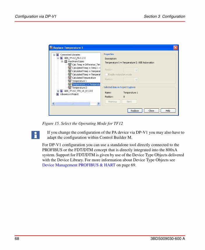
Configuration via DP-V1 Section 3 Configuration
68 3BDS009030-600 A
For DP-V1 configuration you can use a standalone tool directly connected to the PROFIBUS or the FDT/DTM concept that is directly integrated into the 800xA system. Support for FDT/DTM is given by use of the Device Type Objects delivered with the Device Library. For more information about Device Type Objects see Device Management PROFIBUS & HART on page 69.
Figure 15. Select the Operating Mode for TF12
If you change the configuration of the PA device via DP-V1 you may also have to adapt the configuration within Control Builder M.

Section 3 Configuration Device Management PROFIBUS & HART
3BDS009030-600 A 69
Device Management PROFIBUS & HART
Device Management PROFIBUS & HART offers a large portfolio of engineering tools and Device Type Objects to be used in the 800xA system. While Control Builder Mis used for the DP-V0 configuration of the devices, Device Management is mainly used for the DP-V1 configuration.
The Device Type Objects are delivered with the Device Library. To get a new device integrated into your system just drag a device from the library, drop into the relevant structure, and use it in all its aspects. Device Libraries contain ABB and third party device types enhanced with the essential Aspects for
• Configuration• Parameterization• Commissioning/diagnosis• Device documentation• Asset monitoring• Maintenance management (CMMS connectivity)
Figure 16. Components of the Device Management PROFIBUS & HART
Device Management PROFIBUS & HART Section 3 Configuration
70 3BDS009030-600 A
• DMS Calibration Integration.
The Device Type Object also includes a standardized and proven Hardware Definition file for the device packed in a hardware library. By use of the Device Type Object no individual import of the device with the Device Import Wizard is necessary. Furthermore you will benefit by generic solutions based on the standard Device Type Objects.
For more information, refer to System_800xA Device Management PROFIBUS & HART, Configuration (3BDD011934*).
3BDS009030-600 A 71
Section 4 Download and Online Mode
This section describes how to download and go online with a project accessing PROFIBUS DP data.
PreconditionsCheck the hardware configuration of the slave units and the PROFIBUS cabling especially the termination. Verify the DIP switches for setting the slave addresses. Verify that no duplicate addresses are configured.
Before you can download the AC 800M controller ensure that the processor module as well as the CI854/CI854A/CI854B contain the correct firmware. Refer to Control Builder M documentation and online help for further information.
Duplicate address of a slave station cannot be detected by a PROFIBUS master CI854A/CI854B.
Hence the effect of duplicate slave address on the PROFIBUS communication cannot be predicted. User should make sure to set unique PROFIBUS addresses for all slaves connected.
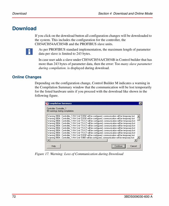
Download Section 4 Download and Online Mode
72 3BDS009030-600 A
DownloadIf you click on the download button all configuration changes will be downloaded to the system. This includes the configuration for the controller, the CI854/CI854A/CI854B and the PROFIBUS slave units.
Online Changes
Depending on the configuration change, Control Builder M indicates a warning in the Compilation Summary window that the communication will be lost temporarily for the listed hardware units if you proceed with the download like shown in the following figure.
Figure 17. Warning: Loss of Communication during Download
‘
As per PROFIBUS standard implementation, the maximum length of parameter data per slave is limited to 243 bytes.
In case user adds a slave under CI854/CI854A/CI854B in Control builder that has more than 243 bytes of parameter data, then the error: Too many slave parameter during compilation. is displayed during download.

Section 4 Download and Online Mode Online Changes
3BDS009030-600 A 73
With CI854/CI854A/CI854B most changes can be downloaded without stopping the PROFIBUS communication. Slaves can be added, deleted or changed online.
For CI854/CI854A, the complete PROFIBUS communication will be stopped only if one of the following bus parameters are changed: • Baudrate
• Node Address for CI854/CI854A/CI854B
• HSA (Highest Station Address)
• Min Slave Interval.
For CI854B, the complete PROFIBUS communication will be stopped if one of the following bus parameters are changed:
• Baudrate
• Node Address for CI854/CI854A
• Min Station delay
• Quiet time
• Gap factor
• BPFlag
• Poll timeout
• Data Control time
In addition a warning will be indicated if the Watchdog Time is changed. This is done because some slaves do not support the online change for the watchdog time although they should.
PROFIBUS slave unit also must support the online change of bus parameters. Otherwise the connection for the specific slave unit is disconnected for a short time. The communication to a specific PROFIBUS slave unit is stopped if the slave configuration is changed and the slave doesn’t support HCIR (Hot Configuration in Run).
For baud rate reconfiguration to low baud rates (9.6 kB and 93.75 kB) on large PROFIBUS configuration (more no. of slaves and large IO bytes per slaves), the response time received by CI854/CI854/CI854B modules from the slave is slow during download. In such reconfiguration scenarios there could be an impact of the slow response on the PROFIBUS communication and also status of the CI854/CI854/CI854B modules in general

Automatic Calculation of PROFIBUS Master Parameters Section 4 Download and Online Mode
74 3BDS009030-600 A
Automatic Calculation of PROFIBUS Master Parameters
During download a calculation of the PROFIBUS master parameters takes place. Depending on the selected baudrate the settings will be recalculated. The calculation uses the actual values as an input. Based on the configured slaves with their input and output data it calculates the new values.
If the value of a parameter is changed it will be indicated in the message pane and the compilation summary window. The new calculated values are written back into the settings tab for CI854/CI854A/CI854B and stored in the project as shown in Figure 18.
Figure 18 shows the different steps for the automatic PROFIBUS master parameter calculation.
If a slave does not support the selected baudrate, the system automatically selects the next lower baudrate supported by all slaves and downloads this baudrate into the controller.
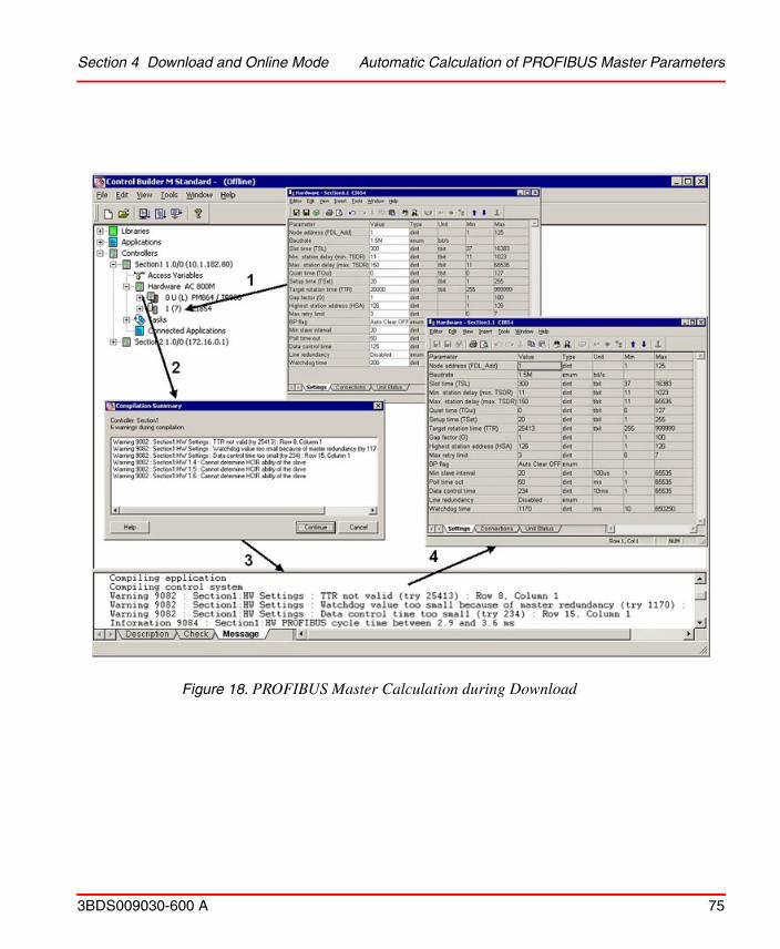
Section 4 Download and Online Mode Automatic Calculation of PROFIBUS Master Parameters
3BDS009030-600 A 75
Figure 18. PROFIBUS Master Calculation during Download
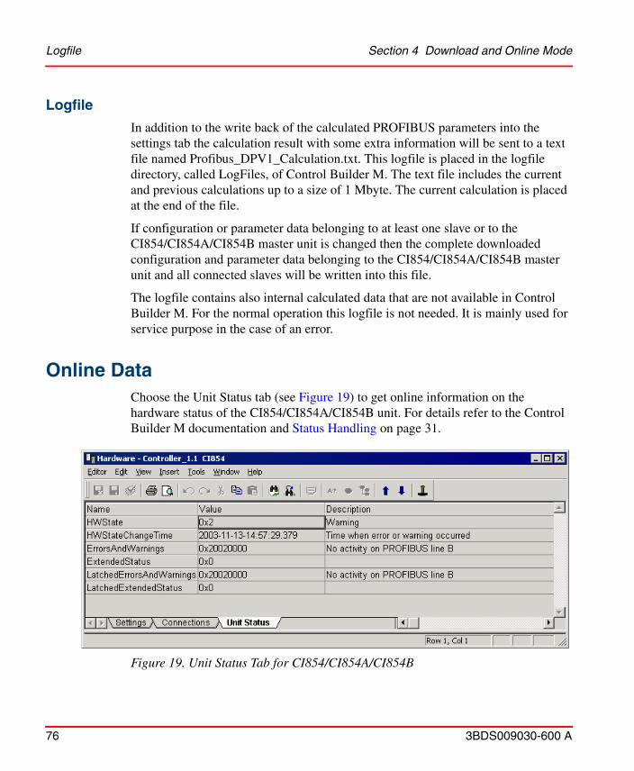
Logfile Section 4 Download and Online Mode
76 3BDS009030-600 A
Logfile
In addition to the write back of the calculated PROFIBUS parameters into the settings tab the calculation result with some extra information will be sent to a text file named Profibus_DPV1_Calculation.txt. This logfile is placed in the logfile directory, called LogFiles, of Control Builder M. The text file includes the current and previous calculations up to a size of 1 Mbyte. The current calculation is placed at the end of the file.
If configuration or parameter data belonging to at least one slave or to the CI854/CI854A/CI854B master unit is changed then the complete downloaded configuration and parameter data belonging to the CI854/CI854A/CI854B master unit and all connected slaves will be written into this file.
The logfile contains also internal calculated data that are not available in Control Builder M. For the normal operation this logfile is not needed. It is mainly used for service purpose in the case of an error.
Online DataChoose the Unit Status tab (see Figure 19) to get online information on the hardware status of the CI854/CI854A/CI854B unit. For details refer to the Control Builder M documentation and Status Handling on page 31.
Figure 19. Unit Status Tab for CI854/CI854A/CI854B
Section 4 Download and Online Mode Behavior of I/O and Communication
3BDS009030-600 A 77
Behavior of I/O and Communication
Insertion and deletion of I/O units
In case of insertion and deletion of I/O units the corresponding outputs are set to zero.
Connection Error
The communication between the CI854/CI854A/CI854B master and the slave is monitored by both units, the master and the slave. In case of an error, specific reactions on the master and the slave side will take place. Please refer also to Monitoring the DP-V0 Communication on page 25.
If the CI854/CI854A/CI854B master unit detects the loss of communication with the slave unit the error “Connection down” will be indicated for the specific slave. The AC 800M controller stops the copying of input data and activates ISP (Input Set as Predetermined) control for the related variables. During “Connection down” the status for Error/Warning and Alarm/Event will not change. If the connection gets re-established the status will be updated.
If the slave unit detects the loss of communication with the master unit it activates the OSP (Output Set as Predetermined) control for the related output channels.
A connection error can be caused by reconfiguration or a temporary error such as cable error. If a temporary error is corrected, the connection will be reestablished automatically.
In case of a connection error, for example due to a disconnected cable, the CI854/CI854A/CI854B will keep the current values for all inputs belonging to the disturbed slave unit.
System Error Section 4 Download and Online Mode
78 3BDS009030-600 A
System Error
On CI854/CI854A/CI854B two watchdogs are implemented that have to be triggered otherwise the module switches into a safe state mode and stops the communication on the PROFIBUS. The connections to all connected slave units get interrupted. ISP control on the AC 800M controller and OSP control on the slave units will get active. To get the CI854/CI854A/CI854B back into the normal operating mode you have to reset the controller, in case of CI854A you also can perform a hot swap of the module instead.
One of these watchdogs is implemented in the hardware of CI854/CI854A/CI854B. It has to be triggered by the firmware every 50 ms. The other watchdog is implemented in the firmware of CI854/CI854A/CI854B and monitors the communication between the controller and the CI854/CI854A/CI854B via the CEX-bus. This watchdog has to be triggered by the controller every second.
3BDS009030-600 A 79
Section 5 CI854 Web server
The PROFIBUS web server interface provides additional feature through a web browser interface. These features are used during commissioning, maintenance or for service purpose in the case of an error.
CI854 Web Server Login PrerequisiteThe web server interface can be accessed through web browsers such as Microsoft Internet Explorer or Mozilla Firefox. Before logging into web server, ensure that the following web browser settings are done in Internet Options > Security tab.
It is recommended to connect to web server from Windows 8 client machine. The browser setting changes in Internet Options > Security tab is only done to connect from a Windows 2012 R2 server.
Ensure that correct browser settings for the connection (for example, no proxy server for the controller address) are set, and the controller must be accessible from the system.
Ensure that TCP/IP forwarding is enabled on Connectivity Servers. For more information, refer to System 800xA Network Configuration (3BSE034463*).

Web Server Login Section 5 CI854 Web server
80 3BDS009030-600 A
Web Server Login It is recommended to connect to web server from Windows 8 client machine. The browser setting changes in Internet Options > Security tab is only done to connect from a Windows 2012 R2 server.
To overcome unsuccessful login attempt into web server, open Internet Options and in the Security tab, ensure that for all the three zones (Internet, Local Intranet, and Trusted Sites), Enable Protected Mode (requires restarting Internet Explorer) check box is cleared as shown in Figure 20.
Figure 20. Internet Options - Security Tab, Zone Settings
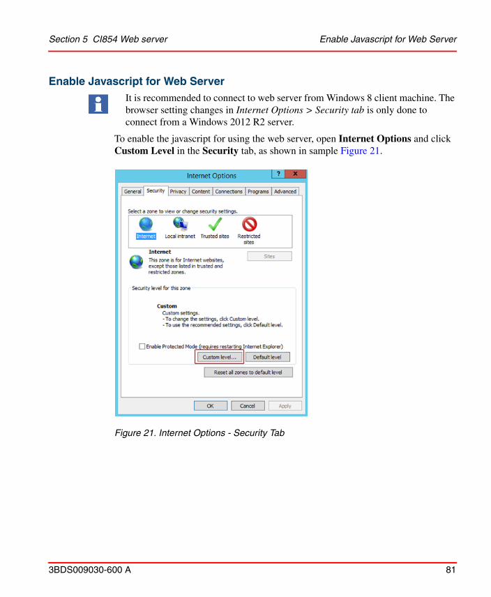
Section 5 CI854 Web server Enable Javascript for Web Server
3BDS009030-600 A 81
Enable Javascript for Web Server It is recommended to connect to web server from Windows 8 client machine. The browser setting changes in Internet Options > Security tab is only done to connect from a Windows 2012 R2 server.
To enable the javascript for using the web server, open Internet Options and click Custom Level in the Security tab, as shown in sample Figure 21.
Figure 21. Internet Options - Security Tab
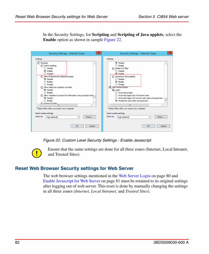
Reset Web Browser Security settings for Web Server Section 5 CI854 Web server
82 3BDS009030-600 A
In the Security Settings, for Scripting and Scripting of Java applets, select the Enable option as shown in sample Figure 22.
Reset Web Browser Security settings for Web Server
The web browser settings mentioned in the Web Server Login on page 80 and Enable Javascript for Web Server on page 81 must be retained to its original settings after logging out of web server. This reset is done by manually changing the settings in all three zones (Internet, Local Intranet, and Trusted Sites).
Figure 22. Custom Level Security Settings - Enable Javascript
Ensure that the same settings are done for all three zones (Internet, Local Intranet, and Trusted Sites).

Section 5 CI854 Web server CI854 Web Server Security
3BDS009030-600 A 83
CI854 Web Server SecurityThe web server is disabled by default. It can be enabled on request using the Enable Web Server option available in Control Builder. This option is visible only when the Control Builder is online and at least one of the modules CI854, CI860 and CI871 is configured
For more information on accessing the enable web server option in Control Builder and general handling of web server in controller, refer to the System 800xA Control AC 800M Configuration (3BSE035980*) and Compact Control Builder AC 800M Configuration (3BSE040935*) Manual.
The login screen for authentication is displayed as shown in Figure 23. Enter the user name and password to login and access the homepage of the web server. The default user name is service and the default password is ABB800xA. To change the password please refer to Change Password on page 110.
Figure 23. Login
The default password is ABB800xA. Replace this with a password that conforms with your organization's security policy at the first possible opportunity. Failure to replace the default password makes the system susceptible to unauthorized access.
Refer to the Password Security topic in System 800xA Administration and Security (3BSE037410*) for recommendations on establishing a password security scheme.
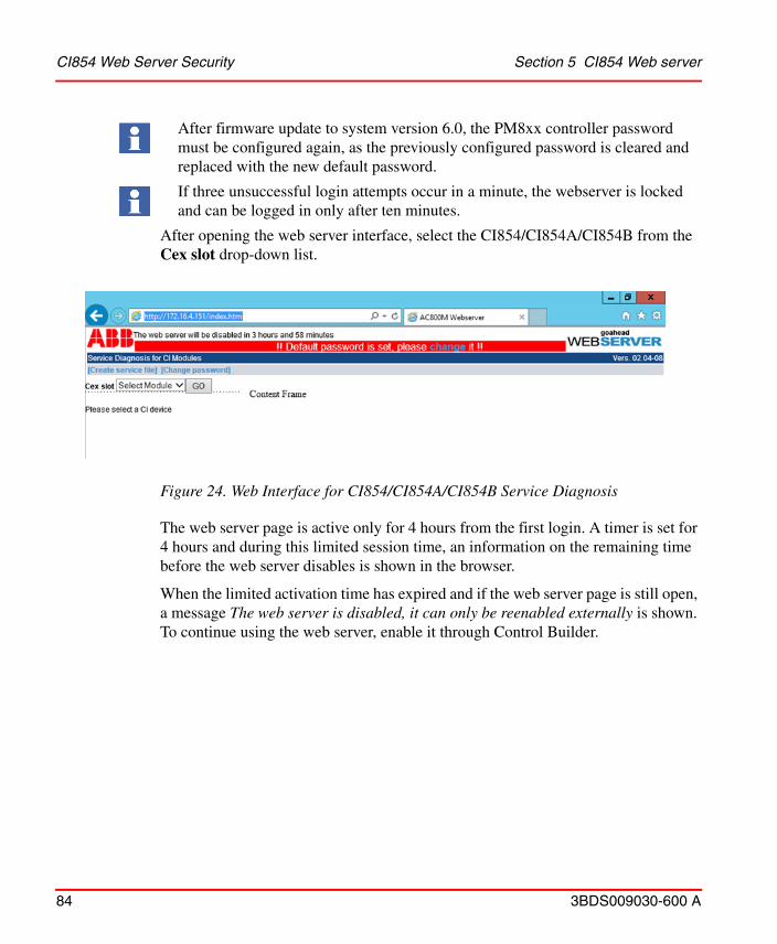
CI854 Web Server Security Section 5 CI854 Web server
84 3BDS009030-600 A
After opening the web server interface, select the CI854/CI854A/CI854B from the Cex slot drop-down list.
The web server page is active only for 4 hours from the first login. A timer is set for 4 hours and during this limited session time, an information on the remaining time before the web server disables is shown in the browser.
When the limited activation time has expired and if the web server page is still open, a message The web server is disabled, it can only be reenabled externally is shown. To continue using the web server, enable it through Control Builder.
After firmware update to system version 6.0, the PM8xx controller password must be configured again, as the previously configured password is cleared and replaced with the new default password.
If three unsuccessful login attempts occur in a minute, the webserver is locked and can be logged in only after ten minutes.
Figure 24. Web Interface for CI854/CI854A/CI854B Service Diagnosis

Section 5 CI854 Web server CI854 Web Server Security
3BDS009030-600 A 85
Table 8 lists the Alarms, Events and Warnings recorded in web server. These are displayed in Plant Explorer and Hardware Status of Control Builder.
Figure 25. Web server Disable
Table 8. Web server Alarms and Events
Message Type Severity
The web server is enabled, but the password has not been changed from default.
Alarm Medium
The web server has been enabled. Event Low
The web server has been disabled. Event Low
The web server timer has been reset. Event Low
The controller password has been changed from. Event Low
Successful login to the controller from <IP>. Event Low
Unsuccessful login attempt to the controller from <IP>. Event Medium
Unsuccessful attempt for controller password change from <IP>. Event Medium
The web server has been enabled. Audit Trail N/A
CI854 Web Server Interface Section 5 CI854 Web server
86 3BDS009030-600 A
CI854 Web Server InterfaceThe web server interface can be accessed through a web browser. To open the web server interface, enter the IP address of the controller in the address bar of the browser and press <Enter>.
The web server window has two frames. The left frame displays the menu items (Function List). Select the menu item on the left to display the respective contents in the content frame on the right.
The view of the content is function specific. For some functions only a simple printout of the available data is done. Some other functions need an additional input before the function can be operated. For those a specific input dialog opens at the upper area of the content frame.
For some specific functions that only read data an automatic refresh to update the data is supported. For those a timer can be activated. The timer is shown at the lower area of the content frame. The timer offers the possibility to change the update cycle time.
The specific functions of the Web Interface are described in the following chapters.

Section 5 CI854 Web server CI854 Web Server Interface
3BDS009030-600 A 87
Figure 26. Functional overview of the Service Diagnosis
Legend Description
1 Service File
2 Change Password
3 Function List
4 Input Dialog
5 Content Frame

CI854 web server Interface Menu Items Section 5 CI854 Web server
88 3BDS009030-600 A
CI854 web server Interface Menu ItemsCI854 web server Interface displays the following menu items:
• SetAddress• LiveList• CycleTime• GeneralStatus• MasterSettings• SlaveDiagnosis• SlaveConfig• Slave-I/O• FirmwareInfo• HardwareInfo• Redundancy Switchover• Errormemory• Debug, DMJ Buffer• Service File• Change Password• Debug - SetCILogFilter
SetCILogFilter option is available only for CI854B Firmware.
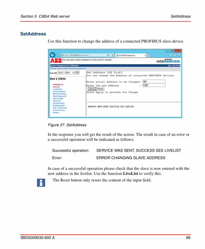
Section 5 CI854 Web server SetAddress
3BDS009030-600 A 89
SetAddress
Use this function to change the address of a connected PROFIBUS slave device.
In the response you will get the result of the action. The result in case of an error or a successful operation will be indicated as follows:
In case of a successful operation please check that the slave is now entered with the new address in the livelist. Use the function LiveList to verify this.
Figure 27. SetAddress
Successful operation: SERVICE WAS SENT, SUCCESS SEE LIVELIST
Error: ERROR CHANGING SLAVE ADDRESS
The Reset button only resets the content of the input field.
SetAddress Section 5 CI854 Web server
90 3BDS009030-600 A
In the case of an error please check that the slave is connected to the PROFIBUS and that it supports this service.
Check that only one slave with address 126 is connected at a time. If you have several new PA devices from the shelf all with the default address 126, then connect them one after the other to the PROFIBUS and change the address before connecting the next device.

Section 5 CI854 Web server LiveList
3BDS009030-600 A 91
LiveList
Use this function to see which devices are connected to the PROFIBUS.
The devices are listed together with the type information telling if it is a master or slave device sorted by the current node address found on the PROFIBUS. By activating the Refresh Timer the Live List can be updated automatically.
Figure 28. LiveList
All devices, masters and slaves, connected to the PROFIBUS are shown, independently of it whether they are configured and in data exchange or not.
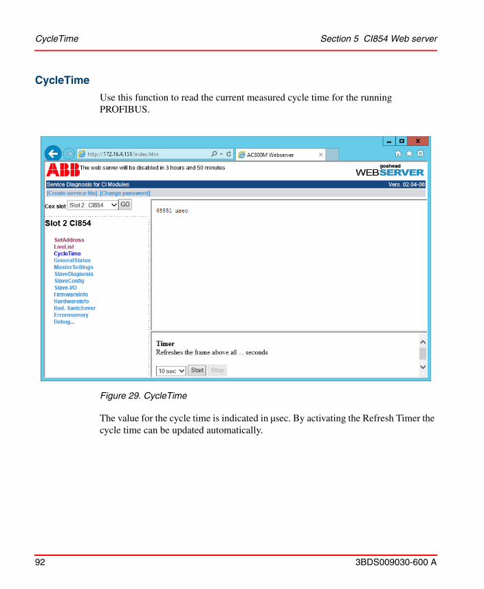
CycleTime Section 5 CI854 Web server
92 3BDS009030-600 A
CycleTime
Use this function to read the current measured cycle time for the running PROFIBUS.
The value for the cycle time is indicated in µsec. By activating the Refresh Timer the cycle time can be updated automatically.
Figure 29. CycleTime
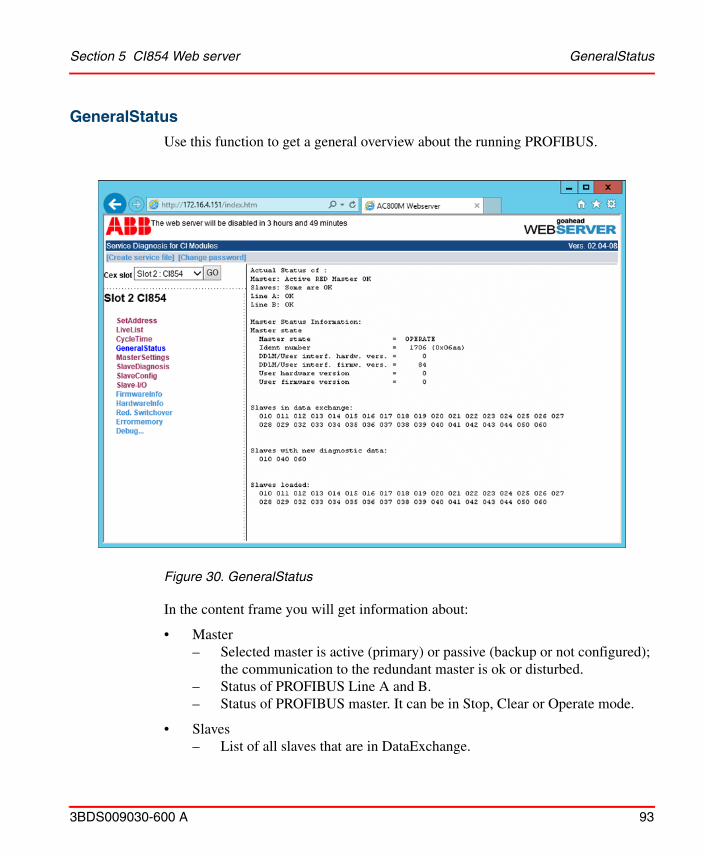
Section 5 CI854 Web server GeneralStatus
3BDS009030-600 A 93
GeneralStatus
Use this function to get a general overview about the running PROFIBUS.
In the content frame you will get information about:
• Master– Selected master is active (primary) or passive (backup or not configured);
the communication to the redundant master is ok or disturbed.– Status of PROFIBUS Line A and B.– Status of PROFIBUS master. It can be in Stop, Clear or Operate mode.
• Slaves– List of all slaves that are in DataExchange.
Figure 30. GeneralStatus

GeneralStatus Section 5 CI854 Web server
94 3BDS009030-600 A
– List of all slaves that have diagnostic data.– List of all slaves that are configured on CI854/CI854A/CI854B.
Only for CI854/CI854A:
In some scenarios where an actual slave with address 125 is not available on the PROFIBUS network or is not configured and there is an All Slaves failed condition, a dummy slave with address 125 is observed in the Slaves Loaded field when there is no other configured slave that has diagnostics data.
This dummy slave is introduced as a part of the internal handling and should not be misinterpreted with an actual slave.

Section 5 CI854 Web server MasterSettings
3BDS009030-600 A 95
MasterSettings
Use this function to see which settings are currently loaded in the CI854/CI854A/CI854B PROFIBUS master unit. In the content frame you will get the following information:
To get the current watchdog time please select SlaveConfig.
Figure 31. MasterSettings

SlaveDiagnosis Section 5 CI854 Web server
96 3BDS009030-600 A
SlaveDiagnosis
Use this function to see which diagnostics are currently present in the slave unit. In the input dialog enter the node address for the slave device you would like to read the diagnostic data for. In the content frame you will get the following information:
If Ext_Diag_Overflow is set (shown in the stations state when active) then the slave unit has currently more diagnostics than it can indicate via the PROFIBUS diagnosis. In this case the number of active diagnosis bytes exceeds Max_Diag_Data_Len that is defined in the GSD file of the slave.
For the interpretation of “Device diagnostic” you have to compare the definitions for UnitDiagBit and UnitDiagArea in the slave GSD-file.
Figure 32. SlaveDiagnosis
Section 5 CI854 Web server SlaveDiagnosis
3BDS009030-600 A 97
With the “Ident diagnostic” each module is indicated with its slot number if the module has currently diagnostic data. In the example above diagnostics are indicated for the modules with the numbers 1 and 9.
With “Channel diagnostic” the active channel errors are listed. Each error is indicated with two lines of information. The first line shows some general information. These are the slot number of the module, the direction if the channel is an input or output, the channel number on the module and the type of the channel. The channel type can be for example word (analog I/O) or bit (binary I/O). The second line specifies the type of the channel error. If the current active error is defined by the PROFIBUS standard then the error will be indicated with the correct message like “Wire failure” as shown in the example. Otherwise only the error-code will be presented. In this case you have to check the definitions for Channel_Diag in the slave GSD-file. The example shows the current error code 31 “HART comm. error” for the analog input module of S900 that is defined by the entry Channel_Diag(31) = “HART comm. error” in the S900 GSD file.

SlaveConfig Section 5 CI854 Web server
98 3BDS009030-600 A
SlaveConfig
Use this function to get the current loaded configuration and parameter data for the slave device. In the input dialog enter the node address for the slave device you would like to read the data for. Press the Read button to update the information.
Figure 33. SlaveConfig
Section 5 CI854 Web server SlaveConfig
3BDS009030-600 A 99
In the content frame the parameter and configuration data downloaded to CI854/CI854A/CI854B are presented for the selected slave. Also the configuration data actual present in the slave unit are shown.
If you have problems to get the slave into DataExchange, please verify that the configuration data on CI854/CI854A/CI854B and on the slave unit itself are identical. In this case verify the hardware configuration on the slave itself with the hardware configuration in Control Builder M.
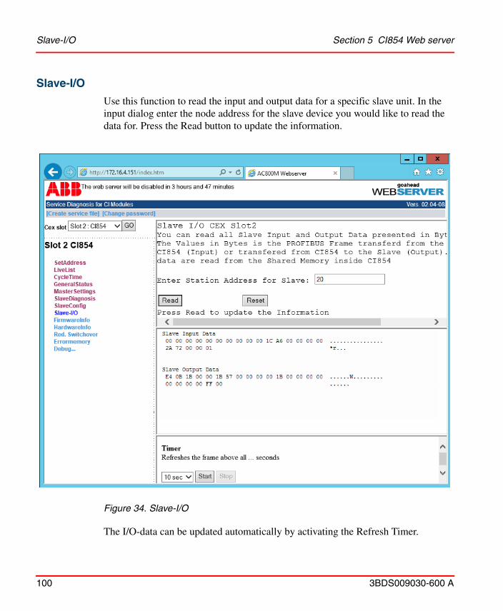
Slave-I/O Section 5 CI854 Web server
100 3BDS009030-600 A
Slave-I/O
Use this function to read the input and output data for a specific slave unit. In the input dialog enter the node address for the slave device you would like to read the data for. Press the Read button to update the information.
The I/O-data can be updated automatically by activating the Refresh Timer.
Figure 34. Slave-I/O
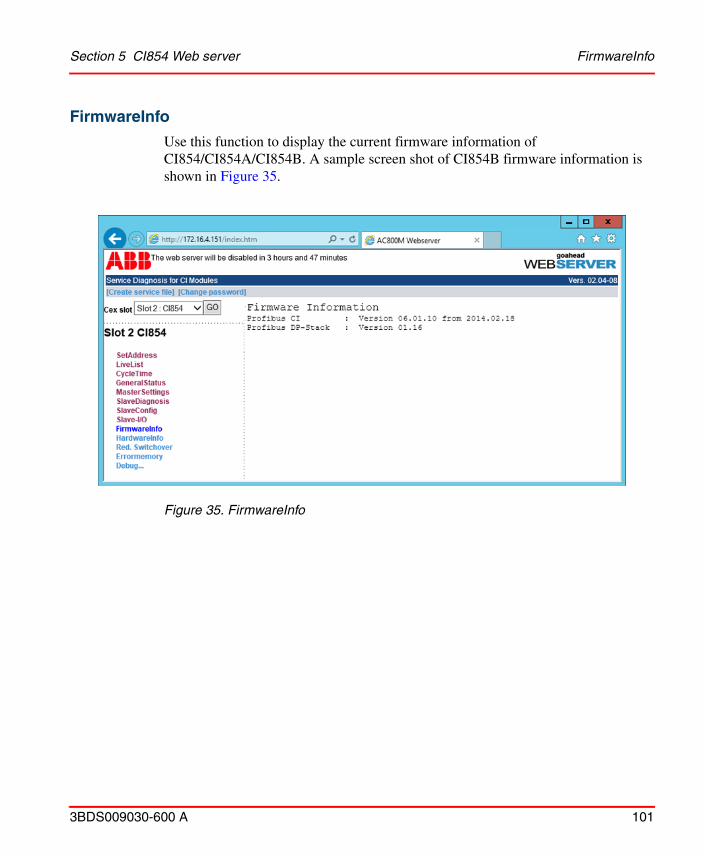
Section 5 CI854 Web server FirmwareInfo
3BDS009030-600 A 101
FirmwareInfo
Use this function to display the current firmware information of CI854/CI854A/CI854B. A sample screen shot of CI854B firmware information is shown in Figure 35.
Figure 35. FirmwareInfo
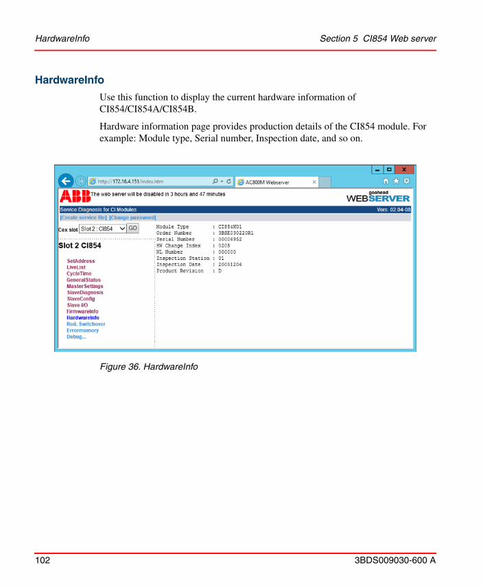
HardwareInfo Section 5 CI854 Web server
102 3BDS009030-600 A
HardwareInfo
Use this function to display the current hardware information of CI854/CI854A/CI854B.
Hardware information page provides production details of the CI854 module. For example: Module type, Serial number, Inspection date, and so on.
Figure 36. HardwareInfo

Section 5 CI854 Web server Redundancy Switchover
3BDS009030-600 A 103
Redundancy Switchover
Use this function to perform a redundancy switchover of a connected PROFIBUS slave device. In the input dialog enter the node addresses for primary and backup slave you would like to perform the switchover for. Press the Apply button to perform the switchover.
In the response you will get the result of the action. The result in case of an error or a successful operation will be indicated as follows:
In case of a successful operation it has to be checked on the slave itself that the switchover took place.
Figure 37. Redundancy Switchover
Successful operation: SERVICE WAS SENT
Error: Error performing function
The function Redundancy Switchover only works with slaves that support the PNO slave redundancy.

Errormemory Section 5 CI854 Web server
104 3BDS009030-600 A
Errormemory
This information is of relevance only for the ABB service engineer in case of an error.
ErrorMemory is supported only for CI854/CI854A.
Figure 38. Errormemory
If you are supposed to provide the Errormemory then please provide it always as a textfile and not as a screen dump. Preferable use the Create service file functionality for that.
Section 5 CI854 Web server Debug, DMJ Buffer
3BDS009030-600 A 105
Debug, DMJ Buffer
Debug is supported only for CI854/CI854A.
With Debug<< a submenu can be started. This information is of relevance only for the ABB service engineer in case of an error. As the most useful information the DMJ Buffer is mentioned here. The DMJ Buffer is a journal memory and very helpful in addition to the Errormemory. To get access to the DMJ Buffer select Debug <<, DMJ and then BUFFER. In the Input Dialog you do not have to enter anything, click the Read button.

Debug, DMJ Buffer Section 5 CI854 Web server
106 3BDS009030-600 A
Figure 39. DMJ Buffer
If you are supposed to provide the DMJ Buffer, then always provide it as a textfile and not as a screen dump. Preferably use the “Create CI854 service file” functionality for that.
Section 5 CI854 Web server Debug - Set Log Filter
3BDS009030-600 A 107
Debug - Set Log Filter Debug > Logs > Set Log Filter option is available only for CI854B Firmware.
Select Debug > Logs > Set Log Filter to see and print the logs for all the modules of CI854B into the CI854B log file or filter the logs and see only the specific module logs.
For Example: To see the logs pertaining to ToolRouting module functionality, user has to provide the trace variable defined for ToolRouting to suppress the logs of the rest of the modules.
Additional information on CI module getting into the fault mode can be viewed from:
– For CI854A - Webserver > Debug > DMJ Buffer.
– For CI854B - Right-click Controller > Remote System > click Show Controller Log.
One of the reasons for this failure could be stopping of stack. In such cases, CI module must be hot swapped to get into operating mode.
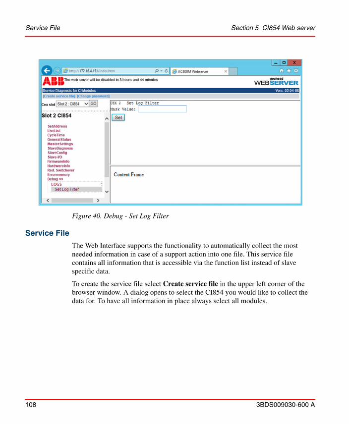
Service File Section 5 CI854 Web server
108 3BDS009030-600 A
Service File
The Web Interface supports the functionality to automatically collect the most needed information in case of a support action into one file. This service file contains all information that is accessible via the function list instead of slave specific data.
To create the service file select Create service file in the upper left corner of the browser window. A dialog opens to select the CI854 you would like to collect the data for. To have all information in place always select all modules.
Figure 40. Debug - Set Log Filter
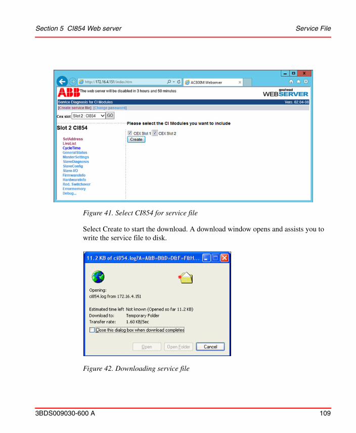
Figure 41. Select CI854 for service file
Section 5 CI854 Web server Service File
3BDS009030-600 A 109
Select Create to start the download. A download window opens and assists you to write the service file to disk.
Figure 42. Downloading service file
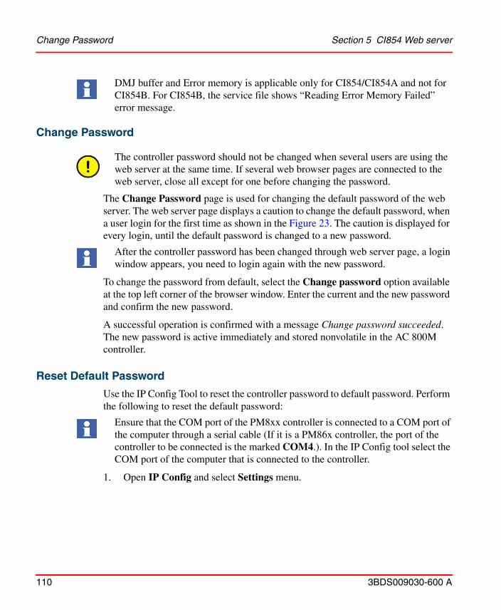
Change Password Section 5 CI854 Web server
110 3BDS009030-600 A
Change Password
The controller password should not be changed when several users are using the web server at the same time. If several web browser pages are connected to the web server, close all except for one before changing the password.
The Change Password page is used for changing the default password of the web server. The web server page displays a caution to change the default password, when a user login for the first time as shown in the Figure 23. The caution is displayed for every login, until the default password is changed to a new password.
To change the password from default, select the Change password option available at the top left corner of the browser window. Enter the current and the new password and confirm the new password.
A successful operation is confirmed with a message Change password succeeded. The new password is active immediately and stored nonvolatile in the AC 800M controller.
Reset Default Password
Use the IP Config Tool to reset the controller password to default password. Perform the following to reset the default password:
1. Open IP Config and select Settings menu.
DMJ buffer and Error memory is applicable only for CI854/CI854A and not for CI854B. For CI854B, the service file shows “Reading Error Memory Failed” error message.
After the controller password has been changed through web server page, a login window appears, you need to login again with the new password.
Ensure that the COM port of the PM8xx controller is connected to a COM port of the computer through a serial cable (If it is a PM86x controller, the port of the controller to be connected is the marked COM4.). In the IP Config tool select the COM port of the computer that is connected to the controller.
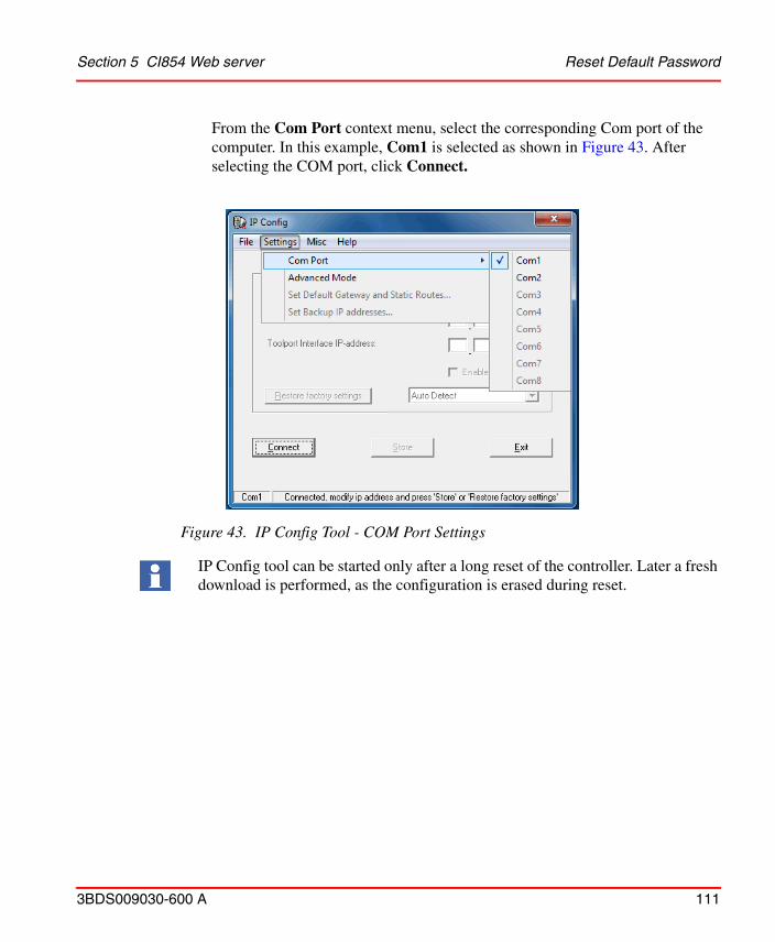
Section 5 CI854 Web server Reset Default Password
3BDS009030-600 A 111
From the Com Port context menu, select the corresponding Com port of the computer. In this example, Com1 is selected as shown in Figure 43. After selecting the COM port, click Connect.
Figure 43. IP Config Tool - COM Port Settings
IP Config tool can be started only after a long reset of the controller. Later a fresh download is performed, as the configuration is erased during reset.
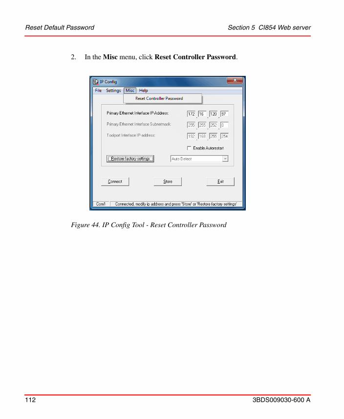
Reset Default Password Section 5 CI854 Web server
112 3BDS009030-600 A
2. In the Misc menu, click Reset Controller Password.
Figure 44. IP Config Tool - Reset Controller Password
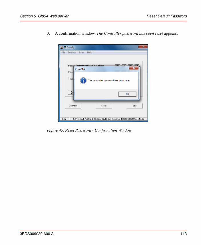
Section 5 CI854 Web server Reset Default Password
3BDS009030-600 A 113
3. A confirmation window, The Controller password has been reset appears.
Figure 45. Reset Password - Confirmation Window

Reset Default Password Section 5 CI854 Web server
114 3BDS009030-600 A
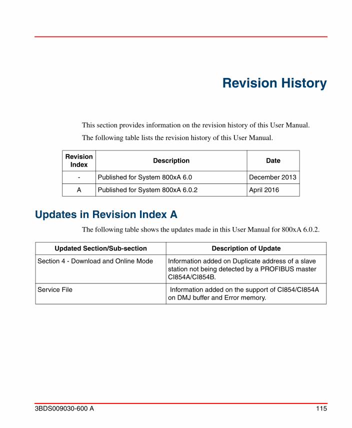
3BDS009030-600 A 115
Revision History
This section provides information on the revision history of this User Manual.
The following table lists the revision history of this User Manual.
Updates in Revision Index AThe following table shows the updates made in this User Manual for 800xA 6.0.2.
Revision Index
Description Date
- Published for System 800xA 6.0 December 2013
A Published for System 800xA 6.0.2 April 2016
Updated Section/Sub-section Description of Update
Section 4 - Download and Online Mode Information added on Duplicate address of a slave station not being detected by a PROFIBUS master CI854A/CI854B.
Service File Information added on the support of CI854/CI854A on DMJ buffer and Error memory.

Updates in Revision Index A
116 3BDS009030-600 A
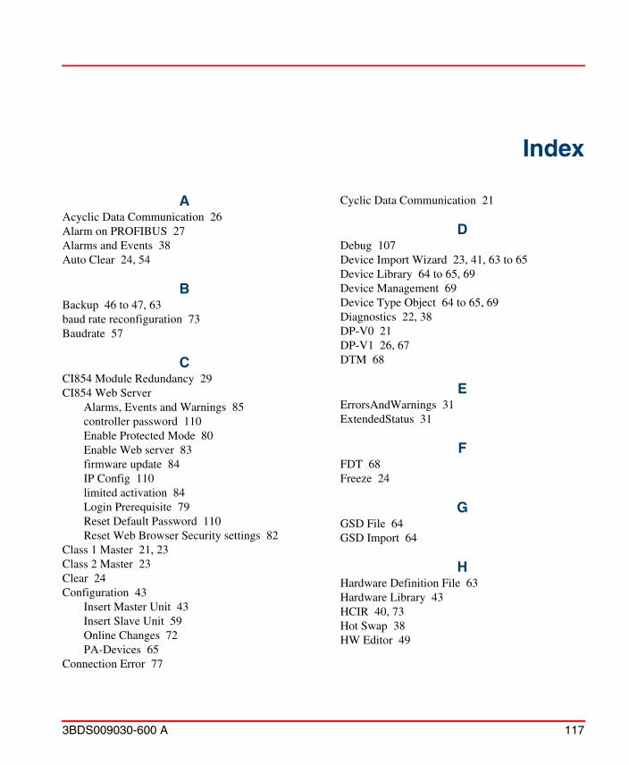
3BDS009030-600 A 117
AAcyclic Data Communication 26Alarm on PROFIBUS 27Alarms and Events 38Auto Clear 24, 54
BBackup 46 to 47, 63baud rate reconfiguration 73Baudrate 57
CCI854 Module Redundancy 29CI854 Web Server
Alarms, Events and Warnings 85controller password 110Enable Protected Mode 80Enable Web server 83firmware update 84IP Config 110limited activation 84Login Prerequisite 79Reset Default Password 110Reset Web Browser Security settings 82
Class 1 Master 21, 23Class 2 Master 23Clear 24Configuration 43
Insert Master Unit 43Insert Slave Unit 59Online Changes 72PA-Devices 65
Connection Error 77
Cyclic Data Communication 21
DDebug 107Device Import Wizard 23, 41, 63 to 65Device Library 64 to 65, 69Device Management 69Device Type Object 64 to 65, 69Diagnostics 22, 38DP-V0 21DP-V1 26, 67DTM 68
EErrorsAndWarnings 31ExtendedStatus 31
FFDT 68Freeze 24
GGSD File 64GSD Import 64
HHardware Definition File 63Hardware Library 43HCIR 40, 73Hot Swap 38HW Editor 49
Index
Index
118 3BDS009030-600 A
IISP Control 77 to 78
LLD 800P 58, 65Linking Device 14, 58 to 59, 65 to 66Logfile 76
MMaster Parameters
Automatic Calculation 55, 74Default Values 57Optimized Settings 55, 74Special Settings 58
Multi Master Systems 25
OOnline Data 76Operate 24OSP Control 77
PPA-Devices 65PROFIBUS Address
Master Unit 51Slave Unit 67, 89
RRedundancy 27
Backup Position 44, 60Line 30Master Unit 28, 46 to 47Slave Unit 29, 62 to 63
RLM 30, 58
SSetCILogFilter 107Settings Tab 50SK2 58 to 59, 66
SK2 and SK3 59SK3 58 to 59, 65 to 66Status Handling
Master Unit 31Slave Unit 37
Stop 24Sync 24
TTTR 27
WWatchdog Time 28 to 29, 51Web Interface 79


Power and productivity for a better worldTM
Contact us
Copyright © 2016 ABB.All rights reserved.
3BD
S00
9030
-600
Awww.abb.com/800xAwww.abb.com/controlsystems
Top Related