


Languages
Pages
Legal

Disclaimer: The ARCADIA project is co-funded by the European Commission under the Horizon 2020 Programme. This document reflects
only authors’ views. EC is not liable for any use that may be done of the information contained therein.
HORIZON H2020-ICT-2014-1
Objective ICT-09-2014: Topics and Methods for Software Development
A novel reconfigurable by design highly distributed applications
development paradigm over programmable infrastructure
D2.3 - Description of the ARCADIA Framework
Editors: P. Gouvas (UBITECH), C. Vassilakis (UBITECH)
Contributors:
E. Fotopoulou, A. Zafeiropoulos (UBITECH), M. Repetto
(CNIT), K. Tsagkaris, N. Koutsouris, N. Havaranis, E. Tzifa, A.
Sarli (WINGS), S. Kovaci, T. Quang (TUB), A. Rossini
(SINTEF), J. Sterle (UL), S. Siravo (MAGGIOLI), G.
Kioumourtzis, E. Charalampous (ADITESS), L. Porwol (NUIG)
Date: 16/11/2015
Version: 1.00
Status: Final
Workpackage: WP2 – ARCADIA Framework Specifications
Classification: Public
D2.3 - Description of the ARCADIA Framework
2 / 47
ARCADIA Profile
Partners
Insight Centre for Data Analytics, National
University of Ireland, Galway Ireland
Stiftelsen SINTEF Norway
Technische Universität Berlin Germany
Consorzio Nazionale Interuniversitario per le Telecomunicazioni
Italy
Univerza v Ljubljani Slovenia
UBITECH Greece
WINGS ICT Solutions Information & Communication Technologies EPE
Greece
MAGGIOLI SPA Italy
ADITESS Advanced Integrated Technology Solutions and Services Ltd
Cyprus
Grant Agreement No.: 645372
Acronym: ARCADIA
Title:
A NOVEL RECONFIGURABLE BY DESIGN HIGHLY DISTRIBUTED
APPLICATIONS DEVELOPMENT PARADIGM OVER PROGRAMMABLE
INFRASTRUCTURE
URL: http://www.arcadia-framework.eu/
Start Date: 01/01/2015
Duration: 36 months
D2.3 - Description of the ARCADIA Framework
3 / 47
Document History
Version Date Author (Partner) Remarks
0.10 15/07/2015 P. Gouvas, C. Vassilakis (UBITECH) Preparation of Table of Contents (ToC)
0.20 27/07/2015 P. Gouvas, E. Fotopoulou, (UBITECH), M.
Repetto (CNIT), N. Koutsouris, N. Xaravanis (WINGS), S. Kovaci (TUB)
Definition of ARCADIA Operational Environment – Section 2
0.30 28/08/2015
M. Repetto (CNIT), C. Vassilakis, A. Zafeiropoulos (UBITECH), N. Koutsouris (WINGS), T. Quang (TUB), J. Sterle (UL), S. Siravo (MAGGIOLI), G. Kioumourtzis, E. Charalampous (ADITESS), L. Porwol
(NUIG)
Definition of the holistic view of the ARCADIA framework and primary
description of individual components – Section 3
0.40 25/09/2015
C. Vassilakis, P. Gouvas (UBITECH), M. Repetto (CNIT), N. Koutsouris, K.
Tsagkaris (WINGS), T. Quang (TUB), J. Sterle (UL), S. Siravo (MAGGIOLI), G.
Kioumourtzis (ADITESS)
Elaborated description of the components of the ARCADIA
Framework – Section 3
0.50 15/10/2015
C. Vassilakis, P. Gouvas, E. Fotopoulou (UBITECH), M. Repetto (CNIT), N.
Koutsouris (WINGS), S. Kovaci (TUB), A. Rossini (SINTEF), J. Sterle (UL), S.
Siravo (MAGGIOLI), G. Kioumourtzis (ADITESS)
Final description of the components of the ARCADIA Framework and
description of the implementation guidelines – Sections 3 & 4
0.50 20/10/2015
M. Repetto (CNIT), C. Vassilakis, P. Gouvas, E. Fotopoulou (UBITECH), E.
Tzifa, A. Sarli (WINGS), S. Kovaci (TUB), A. Rossini (SINTEF), J. Sterle (UL), S. Siravo (MAGGIOLI), G. Kioumourtzis
(ADITESS)
Final version of the deliverable –Editing of Sections 1 and 5, Version for Internal
review
1.00 16/11/2015
P. Gouvas, E. Fotopoulou, A. Zafeiropoulos (UBITECH), M. Repetto
(CNIT), K. Tsagkaris, (WINGS), S. Kovaci, T. Quang (TUB), A. Rossini (SINTEF), J. Sterle (UL), S. Siravo
(MAGGIOLI)
Update based on comments from internal review - Final version

D2.3 - Description of the ARCADIA Framework
4 / 47
Executive Summary
This deliverable poses the foundation for the ARCADIA Framework, actually the conceptual
architecture of the ARCADIA project. The proposed framework is going to lead all the technical
developments within the project, including the implementation of the architectural components as
well as the implementation of the use cases. The ARCADIA Framework is tackling a set of challenges,
mainly targeting at proposing a software development paradigm along with a deployment framework
that enables the interconnection of the software developers’ world and the DevOps’ world.
Such challenges include (i) the design of a novel software development paradigm that is going to
facilitate software developers to develop applications that can be represented in the form of a service
graph –consisted by a set of software components along with the dependencies and interconnections
among them- that can be deployable and orchestratable over programmable infrastructure, (ii) the
design and implementation of an orchestrator (called Smart Controller in ARCADIA) able to undertake
the developed service graph and proceed to optimal deployment and orchestration of the
corresponding service/application and (iii) the design and implementation of a policy management
framework that supports the definition of high and low level policies on behalf of a Services Provider
that can be associated with a service graph or a set of service graphs along with the definition of a set
of metrics for policies management purposes.
It should be noted that in ARCADIA we consider that a Smart Controller is deployed per Service
Provider. Such a Smart Controller is able to operate over a multi-IaaS infrastructure and orchestrate
the deployment and operation of numerous services. Given the development of the envisaged software
development paradigm along with its mapping with the ARCADIA Smart Controller, a distinguishing
characteristic of the proposed approach in comparison with existing or ongoing developments on the
era –up to our knowledge- is that it supports the deployment of service graphs that include the entire
functionality of an application and not only the set of network oriented functionalities, as proposed in
a set of approaches that are tackling the deployment of graphs consisted of Virtual Network Functions
(VNFs) based on the evolving specifications in the Network Function Virtualization (NFV) era.
D2.3 - Description of the ARCADIA Framework
5 / 47
Table of Contents
1 Introduction ............................................................................................................................. 8
1.1 Purpose and Scope ................................................................................................................................. 8
1.2 Methodology ............................................................................................................................................ 8
1.3 Relation with other WPs ...................................................................................................................... 8
2 ARCADIA Operational Environment ................................................................................ 9
2.1 ARCADIA Environment, Roles and Interactions .......................................................................... 9
2.2 Highly Distributed Application (HDA) ......................................................................................... 10
2.2.1 Highly Distributed Application Types ......................................................................................... 12
2.2.2 Highly Distributed Application Lifecycle .................................................................................... 14
2.3 Programmable infrastructure ........................................................................................................ 14
3 ARCADIA Framework ......................................................................................................... 15
3.1 Holistic view of the ARCADIA Framework ................................................................................. 15
3.2 Software Development Paradigm and Annotation Framework ......................................... 18
3.2.1 ARCADIA Component Meta-Model................................................................................................ 18
3.2.2 Annotation Framework ..................................................................................................................... 21
3.2.3 Components’ Lifecycle........................................................................................................................ 24
3.2.4 Programming Interface binding ..................................................................................................... 25
3.3 Components and Graphs Repository............................................................................................ 26
3.4 Development and Deployment Toolkit ....................................................................................... 27
3.4.1 Component Development Environment ..................................................................................... 27
3.4.2 Service Graph Development Environment ................................................................................ 28
3.5 Smart Controller .................................................................................................................................. 32
3.5.1 Resources Manager ............................................................................................................................. 32
3.5.2 Deployment Manager ......................................................................................................................... 34
3.5.2.1 Policy Management ......................................................................................... 35
3.5.2.2 Optimization Framework ............................................................................. 37
3.5.3 Monitoring and Analysis Engine .................................................................................................... 39
3.5.4 Execution Manager .............................................................................................................................. 40
3.6 Multi-tenant Active Components Directory ............................................................................... 41
4 Implementation Aspects of Reference Architecture ............................................... 42
4.1 Version Control System ..................................................................................................................... 43
4.2 Project organization & Built Automation ................................................................................... 43
4.3 Continuous Integration ..................................................................................................................... 43
4.4 Quality Assurance ............................................................................................................................... 44
4.5 Release Planning ................................................................................................................................. 45
4.6 Issue tracking ....................................................................................................................................... 45
5 Conclusions ............................................................................................................................ 46
Annex I: References ................................................................................................................... 47

D2.3 - Description of the ARCADIA Framework
6 / 47
List of Figures
Figure 1-1: Relationship of D2.3 with other Tasks and WPs in ARCADIA .............................................................. 9
Figure 2-1: Highly Distributed Application Indicative Breakdown. ....................................................................... 11
Figure 2-2: Highly Distributed Application Indicative Breakdown – Horizontal scaling. ............................. 12
Figure 2-3: Highly Distributed Application Indicative Breakdown – An HDA formed as a chain of an
ARCADIA Application Tier using an already developed Service chain in the category of Hybrid
applications.................................................................................................................................................................................... 13
Figure 3-1: ARCADIA Framework High Level View ...................................................................................................... 15
Figure 3-2: ARCADIA Architectural Components Vision ............................................................................................ 18
Figure 3-3: Component Facets and their usage .............................................................................................................. 20
Figure 3-4: Normative metamodel of ARCADIA Component .................................................................................... 21
Figure 3-5: Abstract view of an ARCADIA Component’s lifecycle ........................................................................... 25
Figure 3-6: Main roles of the service locator pattern implementation ................................................................. 26
Figure 3-7: Component Model ............................................................................................................................................... 29
Figure 3-8: Graph Model .......................................................................................................................................................... 30
Figure 3-9: Deployable Model ................................................................................................................................................ 31
Figure 3-10: Context Model Facets and their Usage (Deliverable 2.2 [3]) .......................................................... 31
Figure 3-11: Policies Management Component .............................................................................................................. 37
Figure 4-1: Development Lifecycle ...................................................................................................................................... 42
Figure 4-2: Bug Reporting Mechanism ............................................................................................................................... 46
List of Tables
Table 3-1: Indicative declaration of an annotation type ............................................................................................. 22
Table 3-2: Indicative usage of the annotation declared in Table 3-1 .................................................................... 22
Table 3-3: Indicative handling of the annotation ........................................................................................................... 23

D2.3 - Description of the ARCADIA Framework
7 / 47
Acronyms
API Application Programming Interface
CAE Cloud Applications Embedding
DoW Description of Work
HDA Highly Distributed Application
IaaS Infrastructure as a Service
JVM Java Virtual Machine
LXC Linux Container
NFV Network Function Virtualization
NFVI Network Functions Virtualization Infrastructure
NV Network Virtualization
OS Operating System
PM Physical Machine
PoP Point of Presence
QoS Quality of Service
SDN Software Defined Networking
VDCE Virtual Data Centre Embedding
VLAN Virtual Local Area Network
VNE Virtual Network Embedding
VNF Virtual Network Function
VPN Virtual Private Network
WP Work Package

D2.3 - Description of the ARCADIA Framework
8 / 47
1 Introduction
1.1 Purpose and Scope
This document provides detailed description of the ARCADIA Framework, as it is designed within the
WP2 activities of the project. Focus is given on the specification of the ARCADIA applications
development, deployment and management lifecycle in a way that is going to enable application
developers to develop infrastructural agnostic applications in an effective and flexible manner.
Towards the design of the ARCADIA Framework, a set of challenging requirements had to be fulfilled.
Such requirements stem from the need to merge the eras of novel software engineering, the adoption
of DevOps approaches towards the automated (or semi-automated) production of deployment scripts
as well as the design of advanced orchestration mechanisms that support the optimized deployment of
distributed applications over programmable infrastructure. Thus, the definition of the ARCADIA
Framework is based on the design of a set of interoperable components and interfaces able to handle
the aforementioned challenges.
The technological solutions adopted are in line with the current technological trends and especially
the evolvement of technologies such as Network Function Virtualization (NFV) and Software Defined
Networking (SDN) and their interconnection with cloud application deployment models (e.g. following
the TOSCA NFV specifications).
The provided specifications in this document are going to guide the technological developments
within the project. Furthermore, based on the developments realized within the project, any problems
faced with regards to interoperability and efficiency aspects are going to be reported and potentially
lead to minor adaptations in the overall framework. Such adaptations are going to be documented –if
needed- in a revised version of this deliverable.
1.2 Methodology
The specification of the ARCADIA Framework mainly stems from the requirements specified in the
Deliverable 2.1 [2] as well as the conformance with the Context Model defined in Deliverable 2.2 [3].
Based on the identified requirements and the conceptualized applications development, deployment
and operation lifecycle process, the ARCADIA Framework is designed. The Framework is broken down
into a set of components, each one of which provides specific functionalities targeted to specific
ARCADIA users. In more detail, part of the components regards the requirements imposed by software
developers while another part regards requirements imposed by Service and Infrastructure providers.
The design of the ARCADIA Framework is realized following an iterative approach. Upon the
specification of the main components that had to be supported, examination of the potential for
appropriate interconnection of components through the specification of interfaces and the avoidance
of incompatibility issues or bottlenecks has been done. Taking into account the extracted results and
insights, the most prominent architectural choices in terms of the support of the required
functionalities are documented.
1.3 Relation with other WPs
This deliverable is the outcome of the tasks “Task 2.3: Smart Controller Requirements and
Functionalities” and “Task 2.4: Design of ARCADIA Framework” of WP2. It actually regards one of the
most important deliverables of the project since it is the foundation of the technical specifications and
developments that is going to be realized within “WP3: Smart Controller Reference Implementation”,
“WP4: ARCADIA Development Toolkit” and “WP5: Use Cases Implementation and Evaluation”. In more

D2.3 - Description of the ARCADIA Framework
9 / 47
detail, the definition of the Smart Controller’s internal architecture as well as the interfaces for
interaction with the rest ARCADIA components are going to be used within the developments in WP3.
Similarly, the definition of the Development/Editing/Deployment toolkit along with the Annotation
framework are going to lead the development that is going to be realized in WP4. Within WP2, the
information presented in this deliverable is being used towards the work realized in parallel in “Task
2.5: Use Cases Requirements Analysis and Definition of Evaluation Metrics” for the definition of the
use cases that are going to be implemented in the project and their mapping with the ARCADIA
Framework in WP5.
The relation of D2.3 with the various tasks and WPs of the project is depicted in Figure 1-1.
Figure 1-1: Relationship of D2.3 with other Tasks and WPs in ARCADIA
2 ARCADIA Operational Environment
2.1 ARCADIA Environment, Roles and Interactions
The ARCADIA framework as a service is adopted by Service Providers and provided to Software
Developers while a Service Provider handles the Programmable Infrastructure leased by the
Infrastructure provider. The Infrastructure Provider provides computing, storage and network
resources while it supports a minimum set of requirements imposed by the ARCADIA framework. A
developer adopts a user side ARCADIA toolset along with the ARCADIA Repository where developed
components are available. A Service Provider uses also the same toolset and repository for preparing
his services as well as specifying the policies that have to be applied. Required manual operations that
may be a bottleneck or impose administrative cost are minimized.
Within ARCADIA, the following three core roles are identified (Error! Reference source not
ound.):
- Software Developer: he develops applications based on the ARCADIA software development paradigm. He adopts and incorporates into his application service chain already developed
applications either natively - developed from scratch according to the ARCADIA framework- or
existing legacy applications adapted/enhanced according to ARCADIA.
- Services Provider: he adopts the ARCADIA Framework and incorporates the Smart Controller
towards the deployment/management of applications. He designs advanced service graphs

D2.3 - Description of the ARCADIA Framework
10 / 47
based on the available components and service graphs in existing repositories and associates
policies with specific metrics and actions upon the designed service graph. He also prepares
the generic deployment scripts of existing applications that are not developed based on the
ARCADIA software development paradigm but include set of monitoring hooks as well as the
notion of service chaining. For applications developed based on the ARCADIA software
development paradigm, seamless integration of different kinds of DevOps artifacts is
supported, thus the role of the Services Provider operations design and management
personnel is limited (in cases where customizations are required).
- IaaS Provider: he provides interfaces to the Service Provider’s Smart Controller for management and monitoring of large pools of physical and virtual compute, storage, and
networking resources. Registration of resources can be realized through a multi-IaaS
environment. Infrastructure Provider policies and objectives are passed/negotiated to/with
the Service Provider.
2.2 Highly Distributed Application (HDA)
A Highly Distributed Application (HDA) is defined as a distributed scalable structured system of
software entities constructed to illustrate a network service when implemented to run over a cloud
infrastructure. An HDA is a multi-tier cloud application, consisting of application’s tiers chained
with other software entities, illustrating virtual functions (e.g. virtual network functions applied to
the network traffic towards/from and between application’s tiers). Each software entity provides the
ability to horizontally scale (in and out) during runtime in order to handle the workload using the
required resources.
Each Application tier is a distinct application-specific logical operation layer. Each Application tier
is an executable. Each other software entity involved in the Application’s chain is a Virtual Function
(VF) specific logical operation layer. Each software entity as part of a VF is an executable.
Each Application tier and other involved software entity provide/expose to each other a Binding
Interface (BI) letting each other have access to provided functionalities and supporting
communication.
An Application tier using/communicating with a VF not necessarily needs to be able to communicate
with every software entity of the VF but it is required to have access to the BI provided by the VF.
This also stands for the case that an Application Tier communicates with another Application tier that
comprises to a nested chain illustrating and exposing functionalities. The VF as well may be thought
as a nested chain.
While developing an Application Tier, it is necessary to have knowledge of the BI of every other
software component (standalone or as a chain) who’s functionalities are required to be utilized within
this Application Tier. However when especially in the case of a VF required in order to give qualitative
characteristics to the communication between two Applications layers, complexity could be relaxed by
giving the ability and letting the developer describe the type of communication in the form of an
annotation e.g. “secure” while at a next step before building the executable this could be translated to
the proper calls to the BI of the required VF.
The developer of an application tier annotates its code with required qualitative and quantitative
characteristics according to the context model. Annotations can be included within the source code
and be properly translated before building the executable, as well as accompany the executable and
be properly translated by other components of the architecture during executable’s placement and
runtime.

D2.3 - Description of the ARCADIA Framework
11 / 47
It is a core desirable requirement each Application tier or involved software entity to be able to scale
horizontally. Development process will be assisted and supported so that each software component
will be able to replicate itself and run in a different execution environment in order to support
excess load. Further requirements regarding the outcome of the development process which will
facilitate efficient execution of an application over a programmable infrastructure will be analysed
later on in this text.
An indicative HDA is depicted in Figure 2-1 that corresponds to a graph that contains a set of tiers
along with a set of functions implemented in the form of Virtual Functions (VFs). It should be noted
that in ARCADIA we are adopting the term Virtual Functions (VFs) instead of the term VNF that is
denoted in ETSI Network Function Virtualization (NFV) since we do not only refer to networking
functions but to generic functions. Each element in the graph is accompanied with a set of quantitative
characteristics (e.g. set of metrics that can be monitored) and constraints (e.g. resource capacity
constraints, dependencies).
Figure 2-1: Highly Distributed Application Indicative Breakdown.
In Figure 2-2 an application tier (T4) of Figure 2-1 example is shown to horizontally scale.

D2.3 - Description of the ARCADIA Framework
12 / 47
Figure 2-2: Highly Distributed Application Indicative Breakdown – Horizontal scaling.
2.2.1 Highly Distributed Application Types
In ARCADIA, we support the deployment and operation of:
- ARCADIA applications; applications that are going to be developed following the proposed
software development paradigm,
- Legacy applications; existing applications already available in an executable form, and
- Hybrid applications; applications consisting of application tiers from both the afore-
mentioned cases.
Native ARCADIA applications will benefit from the full set of capabilities of the Framework. Regarding
Legacy applications, a subset of offered capabilities would be possible to be available. In order a
chain of a legacy application tiers to be deployable and benefit from the ARCADIA framework, proper
interfacing should be built between application tiers while proper annotations could accompany
the executables. In fact, each legacy executable should be interfaced by developing an ARCADIA
BI which will expose its functionalities and enable communication with other properly enhanced
legacy executables in a common ARCADIA framework style/way. The same stands for hybrid
applications as it concerns the legacy application tiers; an ARCADIA BI exposes its functionalities
and enables communication with legacy or native application tiers while proper annotations
accompany the executable. In order a legacy application tier or legacy application as a chain to be
usable by an ARCADIA application tier at the time of development, it should be properly enhanced
with an ARCADIA BI.
Summarizing and specifying in more detail;
- Each application tier or other software entity involved in the formation of the application
chain, should expose its functionalities and enable communication with other entities
through a Binding Interface (BI).
- This BI should follow a common ARCADIA style which must be designed in detail.
- In order a legacy executable to be able to be incorporated into an application chain including
other legacy application tiers or ARCADIA application tiers, it should have prior be enhanced
by an ARCADIA BI which will make possible exposing its functionalities in a common way and
permit communication with other entities.
- In order a developer of an ARCADIA application to be able to use the functionalities of an
already developed software entity (legacy or not), he should be aware of this entity’s BI.
- A developer may use a single software entity illustrating a set of functionalities or already
developed application chain (ARCADIA, legacy or hybrid) illustrating complex service
functionalities. In this case each already developed chain should make available to the
developer a single service BI (SBI) as a BI of the bundle of tiers illustrating the service
(Figure 2-3).
- An ARCADIA application during development embeds annotations which some of them will
be properly translated while building the executable while others will come with the
executable as accompanying annotations (external file).
- The software developer is responsible for enhancing a legacy application and making
available a BI for it. An enhanced legacy application comes with accompanying
annotations reflecting requirements of the application as well as other specifications. It is as
well the software developer’s responsibility of setting these accompanying annotations.
- A software developer should have access to already developed - available software entities and
their BIs through one or more repositories.

D2.3 - Description of the ARCADIA Framework
13 / 47
- The developer himself will have the right to share his application (as the outcome of the
development process) and make it available to other developers or if he doesn’t wish so, to him
only for future use through a repository. Thus, access to repositories’ components will
support permissions.
- The developer of an application should be agnostic to the infrastructure that will host its
application. However, although through annotations and according to the context model, a
developer provides information regarding the desired characteristics in terms of quantitative
and qualitative constraints, it is not always possible to meet requirements since this is
dependent to the offered capabilities by the infrastructure as well as dynamicity of the
environment. An approach is to let the developer specify its requirements as Strict or Best
Effort. However, strict requirements may lead to be impossible to achieve execution of an
application or even be quite difficult to predict that these will for sure be satisfied all the times.
On the other side best effort is what most (if not all) providers support without giving in any
case the ability of imposing any specific requirement apart from virtual hardware loose
demands from the virtual execution environment. To this end, ARCADIA will set as a target to
honor strict requirements with the flexibility of best effort in cases of a possible error in
predictions while attempting to minimize that possibility of error. However supported
capabilities by an infrastructure is as well something that requires a policy; either run only an
application in infrastructure that supports the required capabilities or treat them loosely.
Figure 2-3: Highly Distributed Application Indicative Breakdown – An HDA formed as a chain of an
ARCADIA Application Tier using an already developed Service chain in the category of Hybrid applications.

D2.3 - Description of the ARCADIA Framework
14 / 47
2.2.2 Highly Distributed Application Lifecycle
From an upper view, the lifetime of an HDA starts from the development phase, followed by the
deployment phase and operation phase and ends with its termination. Each phase incorporates flows
between several components working together to provide for and build an HDA, deploy it assigning
resources from an infrastructure, run it while meeting objectives -developer wise and/or service
provider wise- at all times and assure proper release of resources when terminates its operation.
An agnostic to the infrastructure developer should be led / assisted in a simplified development of a
reusable scalable application which will execute while taking advantage of programmable
infrastructure capabilities and meet its objectives in a way that supersedes the dominant best
effort service during its lifetime while service provider’s policies and objectives regarding the usage
of the infrastructure are met.
Deployment, Operation and Termination are supported by the Smart Controller as the
intermediate between the applications and the infrastructure, while development is supported by
several repositories providing easy access to reusable components and the defined context model
providing access to the set of annotations and descriptions.
2.3 Programmable infrastructure
A Service provider leases resources from the Infrastructure provider. These resources can be virtual
or physical and include computing, storage and networking resources. Programmable network
resources are illustrated as virtual ones as well by the Service Provider and not by the Infrastructure
Provider. In order to facilitate the easy exploitation of programmable resources by developers, not
bind to specific equipment and infrastructure and ease the exposure of attractive capabilities, in most
of the cases that are going to be handled by the ARCADIA Framework, we do not consider direct access
to specific physical resources, although our approach will be able to extend towards this direction as
well. Ideally the Infrastructure Provider should be able to provide virtual resources with a guaranteed
reservation over the physical ones. However since this is not most commonly the case, ARCADIA
algorithms will provide for at least a perceptual quality of service even in the case where guaranteed
quality of service with regards to reserved resources is not available. Applications will be able to
benefit from capabilities illustrated by the Service provider over the leased by the Infrastructure
provider resources by exploiting the synergy of NFV and SDN. The way followed facilitates flexibility
and permits illustrating new capabilities and achieving objectives without binding to specific
infrastructure, equipment and equipment locations. The required routing elements, switching elements,
middleboxes and execution environments will be instantiated and migrate if needed anywhere in the
leased virtual network of resources without restrictions on the physical equipment location.
With regards to the deployment/execution environment of the considered applications, we are
going to refer to the following cases:
- applications running on native Operating System (OS) in case of applications running on an OS
of a Physical Machine (PM);
- applications running on a Container in case of applications running on a hosted Container in an
OS of a PM;
- applications running on a Virtual Machine (VM) in case of applications running on the OS of the
VM that is hosted by a hypervisor, and
- applications running in further nested environments (mostly for testing purposes, e.g. applications running in a Container in an OS of a VM hosted by a hypervisor of a PM).
In the following the ARCADIA architecture to support an application’s lifetime will roll out.

D2.3 - Description of the ARCADIA Framework
15 / 47
3 ARCADIA Framework
The vision of ARCADIA is to provide a novel reconfigurable-by-design Highly Distributed Applications
(HDAs) development paradigm over programmable infrastructure. In this section, the specification of
the ARCADIA framework is provided including the breakdown of the overall framework into a set of
components. Upon the provision of a holistic view of the ARCADIA framework, each component is
described in more detail.
3.1 Holistic view of the ARCADIA Framework
The ARCADIA framework consists of a set of components covering in a holistic way the development,
deployment and management of applications in runtime over the available programmable
infrastructure. A high level overview of the ARCADIA framework is provided in Figure 3-2.
In the upper level of the framework, a set of components are made available for designing, developing
and deploying HDAs. The set of components are used by software developers towards the
development of applications following the ARCADIA software development paradigm, as well as
service providers towards the design of services graphs along with their mapping with policies.
In the middle level of the framework, the ARCADIA Smart Controller deploys the applications over the
available programmable infrastructure and manages the application during the execution time
triggering re-configurations where required based on the defined optimization objectives on behalf of
the application developer and the services provider.
In the lower level of the framework, management of the available compute, storage and network
resources is realized along with establishment of the required monitoring and signaling probes for the
real-time management of the instantiated components and links.
Figure 3-1: ARCADIA Framework High Level View
Given the high level view of the ARCADIA Framework, a more detailed view is provided in Figure 3-2,
along with the specification of the individual components, as follows.

D2.3 - Description of the ARCADIA Framework
16 / 47
A basic component used towards this direction is the Component/Service Graph
Development/Editing/Deployment Toolkit. The toolkit supports a set of views targeted at the various
phases of the application development process (application development, deployment script
preparation, policies specification). The toolkit is also interconnected with the ARCADIA Annotation
framework, the ARCADIA service meta-model (part of the ARCADIA context model, as it is described in
D2.2 [3]) the Component/Graphs repository and the Policies Repository.
As already mentioned, each ARCADIA application is represented in the form of a service graph that is
based on a set of components along with their interconnection. For providing access to the existing set
of components and service graphs, a Components/Graphs Repository is made available to software
developers and service providers. The development philosophy within ARCADIA supports the re-use
of existing components and graphs for the design of applications and services. Furthermore, upon the
validation of the appropriate development of an ARCADIA component/graph, this component/graph is
made available for further use through the Components/Graphs Repository.
The Annotation framework is used during applications development for the inclusion of a set of
annotations at software level on behalf of the software developer. Such annotations are based on
concepts represented in the ARCADIA Context Model and can be interpreted during deployment
targeting at providing hints towards the optimal deployment of the application. The ARCADIA service
meta-model is followed during the design of ARCADIA applications targeting at adopting standardized
ways of service graphs design and specification, including the implementation of common interfaces
and the interconnection among the various components.
The Policies Repository is used for the collection of set of policies on behalf of the services provider.
Such policies can be high level policies or policies directly associated with the potential usage of an
ARCADIA Service Graph. A Policies Editor is used to this end for facilitating service provider (actually
their operations design and management personnel) to define set of rules and actions taking into
account the monitoring hooks/metrics available per Service Graph.
Within the Component/Service Graph Development/Editing/Deployment Toolkit, the software
developer is able to develop native ARCADIA components and make them available –upon validation-
to the Components/Graphs Repository, as well as make deployable service graphs based on native
and/or reusable components or service graphs. The software developer is also able to use the
Annotation framework for specifying annotations, while the implementation of component/service
graph interfaces has to be based on the existing context model. The software developer is also able to
adapt legacy applications transforming them to ARCADIA components, while the software developer
and the services provider are able to make deployable service graphs out of reusable components or
graphs as well as make multi-tenant deployable service graphs. The services provider is also able to
specify the set of policies to be applied as they are made available in the Policies Repository.
Following the creation of a deployment model, a deployment model instance is provided to the Smart
Controller that undertakes the deployment and orchestration of the overall operation of the ARCADIA
application. The Smart Controller is the application’s on-boarding utility which undertakes the tasks of
i) translating deployment instances and annotations to optimal infrastructural configuration, ii)
initializing the optimal configuration to the registered programmable resources, iii) supporting
monitoring and analysis processes and iv) reacting pro-actively and re-actively to the configuration
plan based on the infrastructural state, the application’s state and the applied policies.
The application’s software components –as denoted in the corresponding service graph- are
instantiated on demand by the Smart Controller. The defined monitoring hooks initiate a set of
monitoring functionalities for specific performance metrics. The status of these metrics trigger re-
configurations in the deployed application based on optimisation objectives (as denoted in the
selected policies) along with a set of constraints that are considered during the application

D2.3 - Description of the ARCADIA Framework
17 / 47
deployment and runtime. Resources reservation and release is realized on demand over the
programmable infrastructure. In more detail, the Smart Controller includes the following components:
- the Deployment Manager that undertakes the complex task of undertaking the deployment
model instance and “translating” it into optimal deployment configuration taking under
consideration the registered programmable resources, the current situation in the deployment
ecosystem and the applied policies. The Deployment Manager includes an Optimisation
Framework and the Policy Management component. The Optimisation Framework is
responsible for pro-active adjustment of the running configuration as well as re-active
triggering of re-configurations in the deployment plan, based on measurements that derive
from the monitoring components of the Smart Controller (Monitoring and Analysis Engine)
and the existing policies as provided by the Policy Manager. The ultimate goals of the
Optimisation Framework are two: i) zero-service disruption and ii) re-assurance of optimal
configuration across time. The Policy Management component is responsible for assuring that
the imposed policies on behalf of the Services Provider are adhered across the applications
operational lifecycle.
- the Execution Manager that is responsible for the execution of the deployment plan based on
the instantiation of the required components and the links among them, according to the
denoted service graph in the deployment script. The Execution Manager is also responsible for
implementing the monitoring mechanisms required per component and service graph for the
collection of the information required by the denoted monitoring hooks. Such information is
then provided to the Monitoring and Analysis Engine for further processing. The Execution
Manager provides information for the active components to a Multi-tenant Active Components
Directory. Such information is used by the Deployment Manager for optimally planning the
service graph placement process.
- the Resource-Manager that exposes a specific interface where programmable resources are
registered and managed (reserved/released). Programmable resources can span from
configured IaaS frameworks, programmable physical switching/routing equipment,
programmable firewalls, application servers, modularized software entities (databases, HTTP
proxies etc.). Allocation/Release of resources is realised upon requests provided by the
Deployment Manager.
- the Monitoring and Analysis Engine that is responsible for collecting the required
information –as defined by the monitoring hooks per component and service graph- and
supporting the extraction of insights and predictions upon analysis. Monitoring actually relies
on proper probes that are configured during the deployment phase. Probing is related to active
monitoring techniques. Such techniques can be used to monitor in a near-real-time fashion
metrics in multiple levels e.g. OS-level (memory, cores etc.), application-server-level
(connection pools, queues, etc.) or application-level (heap, stack etc.). However, the Monitoring
and Analysis Engine also supports passive techniques in order to aggregate measurements
from resources that cannot be probed; yet they can be interfaced through their custom API.
Indicative examples are switching and routing devices, firewalls etc. Metrics that are measured
using both techniques are aggregated and used for analysis purposes targeted at the
identification of violations, anomaly detection, epidemiological characteristics in case of faults
as well as the production of a set of predictive and prescriptive analytics.
It should be also noted that the considered components per service graph are deployed in a multi-IaaS
environment along with the associated mechanisms for supporting signalling and measurement feeds.
Monitoring feeds to these mechanisms are provided based on information collected by the ARCADIA
Agent that is included within each ARCADIA component.

D2.3 - Description of the ARCADIA Framework
18 / 47
Figure 3-2: ARCADIA Architectural Components Vision
3.2 Software Development Paradigm and Annotation Framework
3.2.1 ARCADIA Component Meta-Model
As already mentioned, several types of HDA applications exist. These include applications that are
going to be developed following the ARCADIA-proposed software development paradigm (also
addressed as ARCADIA native applications), existing applications that are already available in an
executable form and will be ‘wrapped’ in order to be aligned with the same paradigm and hybrid
applications that combine both models. The common denominator between the aforementioned cases
are:
a. the component meta-model that should be respected by all ARCADIA apps;
D2.3 - Description of the ARCADIA Framework
19 / 47
b. the component’s lifecycle that defines the public distinct states of the component and the
respective signalling protocols that are executed by the ARCADIA architectural components
that affect the state (e.g. Deployment Manager) and
c. the exposed Binding Interface (BI) which allows other HDA apps to interact along with the
types of interaction which can be supported (also referred as types of binding).
We will examine all of these factors one by one, starting from the component-metamodel that
represents the upper model of the most granular executable unit. First of all, an ARCADIA
component should be uniquely identified in the frame of a software ecosystem. In order for a
component to be distinguished, it should be accompanied by specific metadata. The reason why a
component should be distinguishable is that every component should be searchable and able to be
binded. We will refer to component-binding later on, in the current section.
Furthermore, each component should expose a configuration layer in order to allow its
parameterization during instantiation. ‘Expose’ implies that an ARCADIA component provides the
ability (i) to initialize the configuration, (ii) to validate the configuration based on structural (e.g.
data type) and business constraints (e.g. a binding port cannot belong to the range 0 to 1024), (iii)
report the active configuration and (iv) handle gracefully any change to the configuration profile.
Since potential changes may affect the operational status of the component per se or one of its first-
order dependencies, the configuration management should be in line with the ARCADIA component’s
lifecycle. This lifecycle tries to conceptualize the distinct public states of an ARCADIA component
which is extremely valuable from the perspective of the Smart Controller. We will elaborate on the
ARCADIA component lifecycle in the following sections.
Additionally, each component should express each operational requirements. Requirements
represent the parameters that should be interpreted as constraints when the “ARCADIA Smart
Controller” selects the proper IaaS resources that should be used per Component in the frame of one
Service Graph deployment. These requirements are distinguished to resource-related requirements
(e.g. CPU speed, number of Cores) and hosting-related requirements (e.g. Operating system of the VM).
Furthermore, as already mentioned each component should expose a set of BIs. These interfaces will
be used by developers in order to bind them during execution. Beyond the exposed interfaces each
component may have several dependencies from other components. The realization of one
dependency is addressed as a link. Each exposed BI or a required BI may be accompanied by specific
performance metrics. Performance metrics are metrics that are quantified through proper probes
that accompany a component in order to expose measurement streams that are forwarded to a
monitoring server.
In general, performance metrics may characterize at the component level one of the following:
a. the performance of an entire component;
b. the performance of one BI;
c. the performance of a link between two components (i.e. the quality of the dependency).
There is a fourth type of performance metric; yet this is not at the component level but at the service
graph level. These types of performance metrics provide indications of the performance or the quality
of the entire service graph.
Moreover, a component may expose some methods that affect its exposed performance metrics.
These methods cannot be used by other components (i.e. they cannot be binded), yet they can be
invoked by the “ARCADIA Smart Controller” in order to affect the internal state of the component
instance. Indicatively, the ability of a component to scale horizontally or vertically may affect the
response time for a specific request that is handled. This ability has to be also exposed so the ARCADIA
Smart Controller to be able to infer the type of corrective action that has to be performed in case a
D2.3 - Description of the ARCADIA Framework
20 / 47
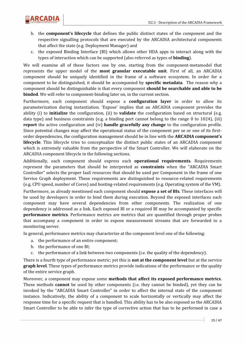
specific misperformance is identified. Finally, each component has to expose some basic governance
methods. These methods (e.g. initiate, update, stop) will be inline with the component’s lifecycle
model. A high level view of the component’s meta-model facets is presented in Figure 3-3.
Figure 3-3: Component Facets and their usage
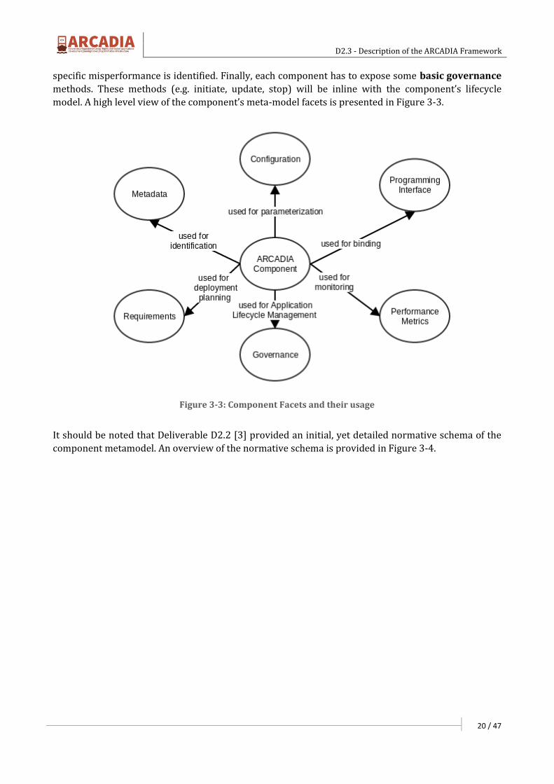
It should be noted that Deliverable D2.2 [3] provided an initial, yet detailed normative schema of the
component metamodel. An overview of the normative schema is provided in Figure 3-4.
D2.3 - Description of the ARCADIA Framework
21 / 47
Figure 3-4: Normative metamodel of ARCADIA Component
The normative component metamodel that is presented above will be used for serialization purposes
when a model is compiled. In other words, a specific repository will host the normative schema
instance which will be auto-generated through the usage of source code annotations’
interpretation. We will elaborate on that in Section 3.2.4.
3.2.2 Annotation Framework
During the elaboration of the ARCADIA Component Metamodel, a normative schema was presented
which is furtherly analyzed in D2.2 [3]. A reasonable question is which is the process that generates
these schemas? According to the ARCADIA conceptual framework, these normative schemas can be
auto-generated by a specific component based on a specific ‘guidance’. This ‘guidance’ can be provided
by formal code-level metadata.

D2.3 - Description of the ARCADIA Framework
22 / 47
Towards this direction, an extremely useful feature named ‘annotations’ is going to be exploited that is
in incorporated in modern high level programming languages such as Java and C#. Annotations are a
form of metadata that provide data about a program that is not part of the program itself. In
other words, a specific set of design-time metadata can be used at the source-code level which will
drive the normative schema creation.
From the software engineering perspective, annotations are practically a special interface. Such an
interface may be accompanied by several constraints such as the parts of the code that can be
annotated (it is called @Target in Java), the parts of the code that will process the annotation etc. An
indicative annotations declaration using Java is presented in Table 3-1.
Table 3-1: Indicative declaration of an annotation type
@Target({ElementType.METHOD })
@Retention(RetentionPolicy.RUNTIME)
@Inherited
@Documented
public @interface ArcadiaService{
String controllerURI() default "htttp://controller.arcadia.eu";
}
According to this declaration, only Java methods can be annotated with the @ArcadiaService
annotation (@Target({ElementType.METHOD })). Furthermore, the compilation procedure will
ignore the annotation; yet the compiler will keep the annotation at the binary level since the it will
be processed during runtime (@Retention(RetentionPolicy.RUNTIME)). Furthermore, if the
annotation method is overridden, the annotation will be automatically propagated to the overridden
method. In addition, annotation may be accompanied by properties that can be set during
declaration. In the aforementioned case, the property ‘controllerURI’ is used to denote the URI of the
hypothetical ARCADIA Smart Controller.
For the sake of comprehension, we will assume that we will build a runtime handler which provides
the following capability to any method that is annotated with our annotation: “the execution time of
the method is communicated to the smart controller”. This is a very dummy feature, yet it is indicative
as far as the annotation usage is concerned. To this end, Table 3-2 provides an indicative usage of the
afore-defined annotation.
As it is depicted, a specific rest interface of a load balancing component is annotated using the
@ArcadiaService annotation. If the same annotation was used at the class level, the compiler would
have generated a compilation exception. Therefore, specific guarantees can be provided regarding the
correct usage of an annotation.
Table 3-2: Indicative usage of the annotation declared in Table 3-1
@ArcadiaService
@RequestMapping(value="/balancer/status/get",method = RequestMethod.GET)
public Status getStatusOfBalancer(){
logger.info("loadbalance.get invoked");
D2.3 - Description of the ARCADIA Framework
23 / 47
…..
}//EoM
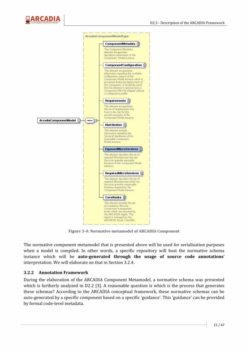
After using the annotation, there should be an “Annotation” handler that performs specific business in
parallel with the normal execution. In our example, the business logic is the measurement of a
method’s execution time. Such business logic can be easily implemented using many techniques. An
indicative one is depicted on Table 3-3. In this example, the technique of Aspect Oriented
Programming (a.k.a. AOP) has been used in order to count the execution time.
Table 3-3: Indicative handling of the annotation
@Around("execution(@eu.arcadia.annotations.ArcadiaService * *(..))")
public Object executionTime(ProceedingJoinPoint pjp) throws Throwable {
long start = System.nanoTime();
Object result = pjp.proceed();
long end = System.nanoTime();
long duration = end - start;
//… do something (e.g. report it to SmartController)
return result;
}
The handling technique above is rather indicative. Each framework selects one handling technique in
order to process annotations. The recent versions of several popular frameworks like EJB31, Spring2,
Hibernate3 make heavy use of annotations. However, as mentioned above, annotations per se are only
definitions that do not encapsulate any business logic. The business logic encapsulation constitutes a
strategic decision of the annotations creator. In general, there are three strategies for annotations’
handling. More specifically these strategies include:
a. Source Generation Strategy: This annotation processing option works by reading the source
code and generating new source code or modifying existing source code, and non-source code
(XML, documentation, etc.). The generators typically rely on container or other programming
convention and they work with any retention policy. Indicative frameworks that belong to this
category are the Annotation Processing Tool4 (APT), XDoclet5 etc.
b. Bytecode Transformation Strategy: These annotation handlers parse the class files with
Annotations and emit modified classes and newly generated classes. They can also generate
non-class artifacts (like XML configuration files). Bytecode transformers can be run offline
1 http://www.oracle.com/technetwork/java/javaee/ejb/index.html 2 https://spring.io 3 http://hibernate.org 4 http://docs.oracle.com/javase/7/docs/technotes/guides/apt 5 http://xdoclet.sourceforge.net/xdoclet/index.html

D2.3 - Description of the ARCADIA Framework
24 / 47
(compile time), at load-time, or dynamically at run-time (using JVMTI6 API). They work
with class or runtime retention policy. Indicative bytecode transformer examples include
AspectJ7, Spring, Hibernate, CGLib8, etc.
c. Runtime Reflection Strategy: This option uses Reflection API to programmatically inspect
the objects at runtime. It typically relies on the container or other programming convention
and requires runtime retention policy. The most prominent testing frameworks like JUnit9
and TestNG10 use runtime reflection for processing the annotations.
From the three strategies that are presented above, the first one will not be utilized at all. However the
second and the third will be used. More specifically, the ‘byte code transformation strategy’ will be
used in order to automate the procedure of normative schema generation regarding the facets of
metadata, requirements and configuration. To this end, specific type of annotations that will be
processed during compilation will generate representative schema instances which are inline with the
ARCADIA Context Model (see Deliverable D2.2 [3]). Finally, the ‘runtime reflection strategy’ will be
utilized in order to dynamically implement specific behaviors that relate to programming
interface binding, measurement of performance metrics and governance. The formal annotations
(e.g. @ArcadiaConfiguration, @ArcadiaMetadata) will be delivered in the frame of WP4.
Finally, it should be noted that during the reference implementation, ARCADIA will make use of JAVA’s
extensibility mechanisms namely; “JSR-175: A Metadata Facility for the JavaTM Programming
Language”11 and “JSR-269: Pluggable Annotation Processing API”12.
3.2.3 Components’ Lifecycle
Up to now, we examined the basic facets of an ARCADIA component. Beyond these facets, a crucial
aspect of all ARCADIA components is their lifecycle. Components that are developed entail some
inherent characteristics such as:
a. They must be able to be orchestrated;
b. They must be able to participate in complex service graphs;
c. They must be able to be governed and
d. They must be monitorable.
A reasonable question is what type of guarantees will be provided by ARCADIA regarding the
aforementioned characteristics? The answer to this question is twofold. The design-time guarantees
will be provided by compile-time business logic which will make use of binary inspection strategies
(see ‘Bytecode Transformation Strategy’ above) that is provided by the annotation framework.
However, the run-time guarantees will be provided by the ‘ARCADIA Smart Controller’ which will
assure (formally assert) that a component or a service graph -which is composed by many
components- is inline with a standardized lifecycle. Although the formal state machine will be
developed in the frame of WP3, an informal abstract view of the lifecycle is presented in Figure 3-5.
6 http://docs.oracle.com/javase/7/docs/platform/jvmti/jvmti.html 7 https://eclipse.org/aspectj 8 https://github.com/cglib/cglib 9 http://junit.org 10 http://testng.org/doc/index.html 11 https://jcp.org/en/jsr/detail?id=175 12 https://jcp.org/en/jsr/detail?id=269

D2.3 - Description of the ARCADIA Framework
25 / 47
Figure 3-5: Abstract view of an ARCADIA Component’s lifecycle
According to the lifecycle, each component is published in a repository (Components & Graph
Repository). When the component has to be instantiated (this can happen for many reasons e.g. it
takes part in a complex graph instantiation) the component applies the configuration that has been
enforced. Before the component passes to the operational state, the dependency management
actions have to be performed. Dependency management implies both the identification of candidate
components and their binding. Binding may refer to an existing running component or may trigger a
new component instantiation (in a recursive manner).
After the successful dependency management, the component announces its operational state to the
‘Smart Controller’. From this moment on, the component can be governed. However, each component
should undertake the responsibility of handling gracefully the update and the deprovision
functionalities. The lifecycle presented above is indicative. The format state transition diagrams that
will be generated will be accompanied by the formal signaling protocol that is required in order to
support all cases of the lifecycle.
3.2.4 Programming Interface binding
Up to now we examined the ARCADIA component metamodel and the component lifecycle which
should be common between all components. According to the component metamodel there is a
specific facet of the component which is used in order for other components to interact with it. In a
distributed environment, ‘interaction’ implies the usage of a remoting technology such as RPC, Web
Services, EJB (for Java), RealProxy(for .NET) etc.
Its remoting technology has each advantages and disadvantages. However, most of them share a
common feature; i.e. they rely on similar design patterns for service exposure and service
consumption. In ARCADIA the service design pattern which is in our interest is the “service locator
pattern”.
The service locator pattern is a design pattern used in software development to encapsulate the
processes involved in obtaining a service with a strong abstraction layer13. This pattern uses a central
registry known as the "service locator", which on request returns the information necessary to invoke
a remote service (Figure 3-6).
13 https://en.wikipedia.org/wiki/Service_locator_pattern
D2.3 - Description of the ARCADIA Framework
26 / 47
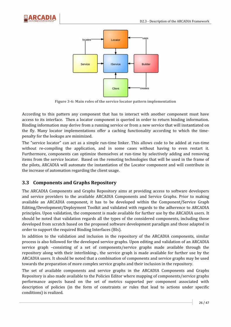
Figure 3-6: Main roles of the service locator pattern implementation
According to this pattern any component that has to interact with another component must have
access to its interface. Then a locator component is queried in order to return binding information.
Binding information may derive from a running service or from a new service that will instantiated on
the fly. Many locator implementations offer a caching functionality according to which the time-
penalty for the lookups are minimized.
The "service locator" can act as a simple run-time linker. This allows code to be added at run-time
without re-compiling the application, and in some cases without having to even restart it.
Furthermore, components can optimize themselves at run-time by selectively adding and removing
items from the service locator. Based on the remoting technologies that will be used in the frame of
the pilots, ARCADIA will automate the instantiation of the Locator component and will contribute in
the increase of automation regarding the client usage.
3.3 Components and Graphs Repository
The ARCADIA Components and Graphs Repository aims at providing access to software developers
and service providers to the available ARCADIA Components and Service Graphs. Prior to making
available an ARCADIA component, it has to be developed within the Component/Service Graph
Editing/Development/Deployment Toolkit and validated with regards to the adherence to ARCADIA
principles. Upon validation, the component is made available for further use by the ARCADIA users. It
should be noted that validation regards all the types of the considered components, including those
developed from scratch based on the proposed software development paradigm and those adapted in
order to support the required Binding Interfaces (BIs).
In addition to the validation and inclusion in the repository of the ARCADIA components, similar
process is also followed for the developed service graphs. Upon editing and validation of an ARCADIA
service graph –consisting of a set of components/service graphs made available through the
repository along with their interlinking-, the service graph is made available for further use by the
ARCADIA users. It should be noted that a combination of components and service graphs may be used
towards the preparation of more complex service graphs and their inclusion in the repository.
The set of available components and service graphs in the ARCADIA Components and Graphs
Repository is also made available to the Policies Editor where mapping of components/service graphs
performance aspects based on the set of metrics supported per component associated with
description of policies (in the form of constraints or rules that lead to actions under specific
conditions) is realized.
D2.3 - Description of the ARCADIA Framework
27 / 47
3.4 Development and Deployment Toolkit
The ARCADIA development toolkit consists practically of two discrete environments; a) one for
Component Development and b) one for Service Graph Development. Each environment offers
different functionalities which will be analyzed. These two environments are complemented by a third
environment which is addressed as Deployment Toolkit which undertakes pre-deployment
configuration aspects.
3.4.1 Component Development Environment
The aim of the component development environment is to help the software developer create valid
components that can be published in the Component Repository. As already thoroughly analyzed,
every ARCADIA component has to comply with a specific metamodel. Compliance is partially achieved
using the annotation libraries that reflect the ARCADIA context model. However, the proper use of
annotations are not guaranteed during design time in the sense that every component that is
developed should contain the proper set of annotations that will make it ‘orchestratable’ during its
deployment. Although there are no design time guarantees the component development environment
will offer the following four functionalities:
1. Component Browsing and Binding: One of the most crucial functionalities of the
environment is the ability to browse the component repository and bind an interface
during the development of a component. The interface binding has to follow a specific
development pattern (e.g. service provider pattern) that allows the consumption of the binding
interface according to the remoting framework that is selected.
2. Annotation Introspection: During the development of a component the developer should
have the ability to generate a normative component model that represents the component
(see Deliverable 2.2 [3]). This normative model will be used in order to publish the component
in the component repository. The normative model generation will be fully automated by
making use of the ability of programming languages to perform annotation introspection i.e. to
process the code-level annotations during compilation.
3. Assertion framework: Another crucial aspect of the development environment is the ability
to certify the correctness of the component as far as its communication with the Smart
Controller is concerned. More specifically, each component is assumed to expose and consume
specific messages from and to the Smart Controller. These messages are in line with a set of
some strict asynchronous messaging protocols that will be defined in order to facilitate aspects
of deployment (i.e. conflict resolution, dependency management) and operation (i.e. migration
actions, scalability actions). Each component should have the ability to be tested against its
compliancy with the signalling protocols prior its publication to the component repository.
This assertion layer will be provided by the component development environment.
4. Registration to the Component Repository: After the finalization of the development of a
component and its certification through the usage of the assertion framework, the component
should be published in the repository in order to be usable for instantiation (in a standalone
manner) and chaining (in a collaborative manner). Registration should also be automated
since each developer upon registration to the ARCADIA component repository will have the
ability to submit several versions of his/her component.
Figure 3-7 illustrates the usage of specific annotations that will be used during the annotation
introspection in order to export a serialized model that will be stored in the Component Registry for a
component that wraps a MySQL database. More specifically, specific annotations will be used for the
declaration of metadata, configuration, component-metrics, link-metrics, binding etc.
D2.3 - Description of the ARCADIA Framework
28 / 47
The validity of the exported model will be checked by the assertion mechanism. After the export of the
component model, the component can participate in chaining scenarios.
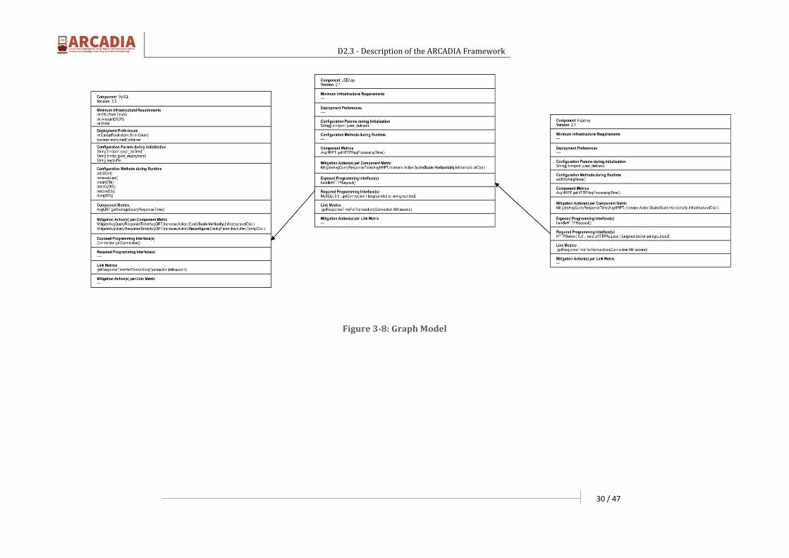
3.4.2 Service Graph Development Environment
The component development environment is a pure developer-centric environment. However, the aim
of the graph development environment is to help the service provider create service graphs that
combine the chainable components that are developed by the component development environment.
The functionalities that are offered by the service graph development environment are the following:
1. Graph Creation and Validation: When a service graph is formulated the most critical issue
that has to be tackled is the complementarity of the components that have to be chained. The
complementarity is achieved by selecting proper ‘binding’ interfaces between requestors and
publishers. Furthermore, a crucial aspect of the graph formulation is the definition of graph
metrics. As already discussed, the components are accompanied by a specific set of metrics
that will be measured during runtime. However, each service graph may be characterized by
additional metrics that are not exposed by the components (e.g. end-to-end delay). The role of
the service graph editor is to define these additional metrics along with the proper probes that
will quantify these metrics.
2. Graph Serialization: Every service graph that is created should be serialized according to the
service graph metamodel (see Deliverable 2.2 [3]). The serialized model is saved to the Service
Graph repository so as to be either edited or instantiated by a service provider.
In an analogous way to Figure 3-7, Figure 3-8 illustrates the design of a service graph that includes a
database (MySQL), a JEE application and a HAProxy for load balancing. The complementarity of the
interconnected components is guaranteed by the graph editor.

D2.3 - Description of the ARCADIA Framework
29 / 47
Figure 3-7: Component Model
D2.3 - Description of the ARCADIA Framework
30 / 47
Figure 3-8: Graph Model

D2.3 - Description of the ARCADIA Framework
31 / 47
3.4.3 Deployment Toolkit
The deployment toolkit builds on top of a service graph and its goal is to generate the deployment
descriptor. The deployment descriptor contains a service graph along with a set of constraints that
have been declared during the policy definition. Figure 3-9 represents the runtime view of the graph
that is presented on Figure 3-8.
Figure 3-9: Deployable Model
Figure 3-10: Context Model Facets and their Usage (Deliverable 2.2 [3])

D2.3 - Description of the ARCADIA Framework
32 / 47
As it is depicted on Figure 3-9, the three components namely C1 (represents the MySQL Database), C2
(represents the JEE App) and C3 (represents the HAProxy) are deployed in three execution containers
namely EC1, EC2 and EC3. The placement of the components to the execution containers took place
based on the optimization algorithm of the execution container (this will be analyzed later on). The
optimization algorithm will take under consideration the enforced policies of the service provider that
have to be satisfied.
The policies refer to the various metrics that can be constrained. In the specific example, these
metrics include a) MC1, MC2 and MC3 which are the Component-Metrics, b) MEC1, MEC2 and MEC3
which are the Execution Container Metrics c) ML21 and ML32 which are the link metrics between C1,
C2 and C3 and finally d) GM which are the metrics that are defined during the graph creation. These
four categories of metrics can be potentially constrained in any service graph.
As a result, the deployment toolkit is responsible to generate the deployment model based on a
selected policy. The deployment toolkit generates a serialized model in analogous way to the
component development environment and the service graph environment. Figure 3-10 illustrates the
various facets of the ARCADIA Context Model as presented on Deliverable 2.2 [3].
The correlation between the various modeling artefacts and the architectural components that
generate them is obvious. The Component Model is generated by the development environment by an
automated way using the Annotation Model. The Graph Model is generated by the Service Graph
Editor while the Policy Model is applied on top of a Service Graph using a respective editor.
Finally, the Deployment Service Plan Model is generated by the Deployment Toolkit based on the input
of the optimization framework. The actual placement of the components (performed by the execution
manager) generates the Service Runtime Model.
3.5 Smart Controller
In the following we provide a detailed description of each component of a Smart Controller while
the synergy among the various components becomes clear. The primitive functions supported by
each component are provided while pending decisions regarding implementation specifics which
are under ongoing research and feasibility testing are revealed.
3.5.1 Resources Manager
The Resources Manager exposes a specific interface where programmable resources are
registered and managed. It communicates with the IaaS Provider through the exposed IaaS API in
order on one hand to request/have a synchronized view of the programmable resources offered
and their availability, which will feed to the deployment manager to decide the deployment
plan, and on the other hand to reserve according to the plan, the required for an application
resources or release them when no more needed.
The IaaS provider exposes a view of the resources available for the Service provider. This does not
mean that the IaaS provider exposes to a Service Provider its physical network structure but a set of
interconnected virtual or physical resources available for reservation; in other words it exposes
a virtual network of virtual or physical nodes and associated capacity constrained resources. The
available resources description received from the IaaS Provider has to permit the Resource
Manager to be able to visualize as a graph a virtual network of virtual nodes of several types and
associate with each virtual node and each virtual link a set of capacity constrained resources along
with other associated QoS metrics.
The description of offered resources and their availability, provided by the IaaS Provider which
permits the Service Provider to have a view over the offered infrastructure, should be updated on
D2.3 - Description of the ARCADIA Framework
33 / 47
the event of a change. On a demand for application deployment over the infrastructure, the
deployment manager is called, through its optimization engine, to solve an allocation problem
having as input the graph of the offered capacity constrained resources (along with their
availability) and produce as output a reservation plan. Considering that requests for application
deployment may be more than one at a time, a synchronization/prioritization scheme has to be
deployed in order to avoid resource reservation conflicts. Furthermore, special care should be taken
when more than one Service Providers have access to the same available resources in order to deal
with resource reservation conflicts.
Resources manager is responsible as well for the instantiation of an executing environment,
through its communication with the IaaS API, which will follow the reservation of resources action at a
later time when the Execution Manager will initiate the process of transferring HDA components to its
execution environment and setting them into operation mode while as well will set and operate
ARCADIA agents for monitoring and interaction purposes at each “execution container” of the
execution environment.
Each infrastructure makes available several Programmable Resources which span from configured
IaaS frameworks to programmable physical switching/routing equipment.
An infrastructure maybe thought as a network of geographically dispersed Resources Repositories
where one or more Resources Pools of a node type exist. Recursion may stand either for resources
repositories or pools; e.g. a resource pool within a resource pool. For example a repository maybe a
data center where exist several hypervisors as resource pools for Virtual machines (VMs), several VMs
as resource pools for containers (e.g. LinuX Containers), physical machines, physical or virtual
switching/routing equipment.
An HDAs application network maybe illustrated as an overlay either within a repository or a
resource pool or across various repositories of a domain (where a domain is an IaaS) or across various
repositories of several domains. Being able illustrating every possible node type or link as a virtual
one, upon request and on the fly while not depending on specialized hardware existing in specific
locations is considered to provide the most flexible environment for allocating resources for the execution
of HDAs. However there are cases where a Service Provider leases and makes available physical resources
for special purposes; such a case is supported as well by the ARCADIA framework.
The primitive actions need to be supported by the Resources Manager are:
1. Get offered resources view: A request through the IaaS API for a description of currently
offered resources and their availability.
2. Reserve Resources: A description of resources to be reserved passed to the IaaS Provider
after the appropriate call through the IaaS API.
3. Release Resources: A description of resources to be released passed to the IaaS Provider
after the appropriate call through the IaaS API.
4. Instantiate execution environment: A request through the IaaS API to instantiate an
execution environment according to a prior reservation plan. This instantiation is triggered by
the Execution Manager through its communication with the Deployment Manager which in
turn passes it to the Resources Manager.
At all times the Deployment Manager may Request the offered resources view and Push a
reservation plan to be realized by the Resources Manager while the IaaS provider may Push a
change of the offered resources view most commonly regarding a change in the availability of
offered resources.
D2.3 - Description of the ARCADIA Framework
34 / 47
In the next short period, detailed modelling of the resources and specification of the description
format will be provided. Furthermore, algorithms for avoiding resources reservation conflicts
will be devised and provided as well.
3.5.2 Deployment Manager
The Deployment Manager is responsible for the complex task of “translating” a produced
deployment model instance into optimal deployment configuration taking under consideration
the registered/offered programmable resources, the current situation in the deployment ecosystem
and the applied policies.
A deployment model instance in fact is a description of a service graph associated with annotations
regarding resource capacity demands and other requirements. The needed components/deployment
model executables that compose this service graph are retrieved from the Component/Graph
Repository. In certain cases where a component in the graph, providing certain functionality, is not
required to be a private-isolated one, this component may illustrate its functionality as a tenant to a
multi-tenant active component. For example, such a component may be a Web server or a Firewall
already running and offering its functionality to multiple-tenants. Such an approach may provide for a
more efficient resource usage through sharing whenever this is convenient and does not contradict
with the notion of flexibility in deployments by creating location specific hot spots. This may be though
as an add-on facility to resource usage efficiency, and not as a restriction that contradicts to the
flexibility promoted by our approach.
A set of requirements accompanying a service graph to be deployed either initiated by the developer
or adopted as an offered (mandatory) to the developer policy or imposed as a strict Service Provider’s
policy with the contribution of the Policy Management component are translated by the
Optimization Framework engine into an optimization – placement/deployment problem
reflecting its objectives and constraints. Input to this problem is the offered infrastructure
resources view along with resources availability, pulled from the Resources Manager while output is
a resources reservation plan to be illustrated by the Resources Manager. Actual instantiation of all
the needed components and execution is in turn handled by the Execution Manager. Instantiation
of an execution environment is triggered by the Execution Manager but illustrated as a response to
Execution Manager’s request by the Deployment Manager which passes the request to the Resources
Manager which in turn realizes the instantiation through its interfacing with the IaaS API.
During an application’s lifetime, in order to meet the objectives and requirements, several
reconfigurations may be triggered as a decision of the Monitoring and Analysis Engine initiated
by the Execution Manager as a request to the Deployment Manager for re-solving the
aforementioned placement/deployment problem.
The Optimization Framework Engine is responsible for providing fast solutions to the problem.
Since these types of resource allocation/placement problems are time consuming to produce an
optimal solution and proven to be NP-hard, efficient heuristics to produce near optimal solutions
in short times are required to be devised.
The primitive actions need to be supported by the Deployment Manager are:
1. Request the offered resources view from Resources Manager: Request a view of the offered
resources along with their availability in the infrastructure provided.
2. Push a reservation plan to Resources Manager: Push a list of resources reservation to be
realized.
3. Push an instantiation of an execution environment to Resources Manager: Pass a request
for instantiation of an execution environment to Resources Manager which is triggered by the
Execution Manager.
D2.3 - Description of the ARCADIA Framework
35 / 47
4. Pull multi-tenant active components view from Multi-tenant Active Components Directory:
Request a view of the multi-tenant components running including their placement in the
virtual infrastructure provided as well as their availability.
5. Pull deployment model executables from Component/Graphs Repository: Get the required
executables described in the deployment model instance to illustrate an actual service chain
for deployment.
6. Push a deployment model execution plan to Execution Manager: Feed the Execution
Manager with the reservation plan, deployment plan and actual service chain for deployment.
The core components of Deployment Manager; Policies Management and Optimization
Framework, are described in the following.
3.5.2.1 Policy Management
The ARCADIA Policy Management component is targeting at managing the policies definition,
enforcement and conflict resolution on behalf of the Services Provider. The internal architecture of
the Policy Management component is depicted in Figure 3-11. It regards the application of policies
taking into account the overall orchestration requirements for services provision involving multiple
subsystems, and can be applied to the general case of any cloud-based service, following parallel
activities realised within the IETF NFV research group [1].
In ARCADIA, policies are applied on behalf of the Services Provider. The Services Provider is able to
define high level and lower level policies that can be applied in a holistic way taking into account all
the provided services, as well as the peculiarities of each involved service graph. Furthermore,
policies definition and description is also taking into account preferences and constraints denoted –
in the form of annotations- by software developers with regards to optimal execution of the
considered software (e.g. indications with regards to intensive computational part of a software).
Policies are going to be used for enforcing business rules as well as specifying resource constraints
over the programmable infrastructure. It should be noted that in ARCADIA, policy making is applied
over multi-IaaS infrastructure.
The main functionalities supported by the policy management framework include:
- Description of set of policies based on the development of a Policies Editor: Policies are
going to be discriminated into high level policies that regard generic objectives that have to
be achieved in a global level (e.g. energy efficient operation of the programmable
infrastructure) and lower level policies that regard focused objectives that have to be
achieved within the deployment and operational lifecycle of a service graph. Each lower level
policy is going to be based into a definition of a set of constraints (hard constraints that
cannot be violated and soft constraints that can be relaxed and partially violated in case of
conflicts) along with the definition of a set of rules that are going to trigger specific actions
under given conditions. Such constraints, rules, conditions and actions are going to be
associated with a set of metrics/concepts denoted within the ARCADIA context model (based
on its current version in D2.2 [3] and upcoming extensions). Indicative metrics that can be
used for rules description include the following: availability (or failure) of a component
instance and a link instance, a topological location of a component instance, CPU and memory
utilization rate of a component instance, a throughput of a component instance, energy
consumption of a component instance, bandwidth of a link instance, packet loss of a link
instance, latency of a link instance, delay variation of a link instance. The denoted policies are
stored in the Policies Repository and are made available for usage from the
Component/Service Graph deployment toolkit.
- High level policies affect all the supported service graphs and are mostly associated with the way that the infrastructure is managed. Thus, the objectives along with potential constraints
D2.3 - Description of the ARCADIA Framework
36 / 47
are provided in this case to the Optimisation Framework and take high priority. The
mapping of high level policies to lower level policies is a challenge on its own and necessitates
the intervention of the Services Provider.
- Lower level policies association with an under deployment service graph is realised within
the Component/Service Graph deployment toolkit. Then, the request for deployment based
on the selected policy is provided to the ARCADIA Smart Controller, and specifically the Policy
Management component within the ARCADIA Deployment Manager. Upon the receipt of a
request, a new deployment that has to be realised has to be examined for potential conflict
detection. In case of a detected conflict, conflict resolution mechanisms are applied and in
case that such a resolution can be achieved, the policy is enforced for this deployment instance.
The optimal deployment plan taking into account the policy’s definition is prepared by the
Optimisation Framework of the ARCADIA Deployment Manager. In case that the conflict
cannot be resolved, then, based on the prioritization of the provided services the new request
has to be rejected or an existing service has to be modified/stopped along with the release of
the reserved resources. Policies conflicts detection and resolution is going to take into account
soft and hard policy constraints, local and global policies enforcement aspects, static versus
dynamic versus autonomic policies.
- Given the acceptance for enforcement of a policy, the request for a new deployment or an adaptation of an existing deployment is handled by the Optimisation Framework. Policies
translation mechanism to configuration aspects in multi-IaaS environments are going to
be supported. Actually, based on the defined service chaining scheme and the denoted rules,
actions and constraints, mapping of policies in diverse deployment environments is going to be
supported during the determination of the optimal placement and scheduling configuration
per service graph.
With regards to the information model that is going to be used for policies description, we are
going to be based on the extension of the current version of the ARCADIA context model. The
extension is going to be based on the description of similar concepts in existing information
models such as the DMTF’s Common Information Model (CIM14). Another alternative is to be based
on Congress15 that aims to provide an extensible open-source framework for governance and
regulatory compliance across any cloud services (e.g. application, network, compute and storage)
within a dynamic infrastructure.
14 http://www.dmtf.org/standards/cim
15 https://wiki.openstack.org/wiki/Congress
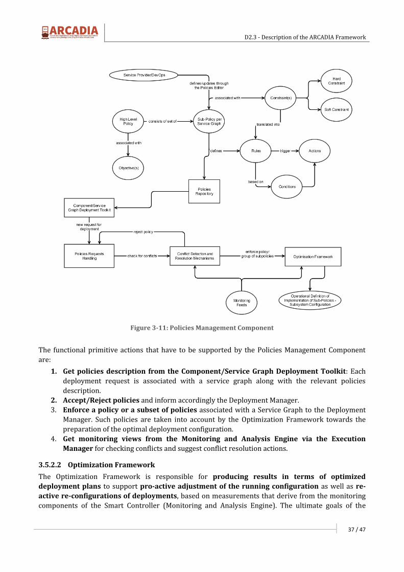
D2.3 - Description of the ARCADIA Framework
37 / 47
Figure 3-11: Policies Management Component
The functional primitive actions that have to be supported by the Policies Management Component
are:
1. Get policies description from the Component/Service Graph Deployment Toolkit: Each
deployment request is associated with a service graph along with the relevant policies
description.
2. Accept/Reject policies and inform accordingly the Deployment Manager.
3. Enforce a policy or a subset of policies associated with a Service Graph to the Deployment
Manager. Such policies are taken into account by the Optimization Framework towards the
preparation of the optimal deployment configuration.
4. Get monitoring views from the Monitoring and Analysis Engine via the Execution
Manager for checking conflicts and suggest conflict resolution actions.
3.5.2.2 Optimization Framework
The Optimization Framework is responsible for producing results in terms of optimized
deployment plans to support pro-active adjustment of the running configuration as well as re-
active re-configurations of deployments, based on measurements that derive from the monitoring
components of the Smart Controller (Monitoring and Analysis Engine). The ultimate goals of the
D2.3 - Description of the ARCADIA Framework
38 / 47
Optimisation Framework are to produce deployment plans to satisfy: i) zero-service disruption and
ii) optimal configuration across time.
Several factors should be avoided and expressed as constraints when placing and assigning resources
to HDAs in an optimal way. Such indicative factors to be avoided are Resource contention; a single
resource or utility is being accessed by two different applications at the same time, Scarcity of
resources; there are not enough resources to deal with the workload, Resource fragmentation;
valuable resources lie around in a highly disorganized manner, Over-provisioning; more resources
are being assigned than required, and Under-provisioning; not adequate resources assigned.
Furthermore, objectives and constraints to be satisfied should express developer’s requirements
regarding the deployment and execution of an HDA as well as Service Provider’s policies and
objectives. A methodology need to be devised to filter all requirements and map them to
objectives and constraints according to priorities set or drive the procedure till a deployment model
instance is created, in a sense that the constrained programming problem to be solved and produce a
deployment plan will be feasible and not fed with conflicting requirements to be satisfied.
The optimization framework component in fact is the “engine” to solve constrained programming
problems. The problems it is called to solve have to do with: i) Producing a deployment plan for the
initial deployment of an HDA and ii) Producing a new deployment plan, incremental, partially or
completely different, for an already running HDA. The latter maybe triggered either a) to satisfy the
needs of an HDA while running in terms of scalability to cope with demand or to sustain quality
requirements, b) to prevent/deal with a Service provider’s policy violation or sustain meeting Service
provider’s objectives, iii) to satisfy the requirements of a newly deployed HDA which couldn’t be
satisfied otherwise.
The Optimization Framework component is responsible for providing fast solutions to the problem of
producing deployment plans. A deployment plan indicates which of the available resources are to be
reserved and utilized for the execution of an HDA. Such an “embedding” of an HDA to an
infrastructure may be considered as an extension of already studied in the literature problems such as
the Virtual Network Embedding (VNE) problem, the Virtual Data Center Embedding (VDCE)
problem and the Cloud Application Embedding (CAE) problem. All these problems -along with the
considered one as an extension of them- fall into the category of NP-hard problems. Thus, obtaining a
solution to the problem may be quite computational intensive and time consuming, especially as the
input to the problem gets large. This is not desired in our case where decisions should be taken on the
fly especially when an HDA is in operation mode and continuous operation with quality characteristics
should be maintained. This strict restriction relaxes somehow when the initial deployment of an HDA
(HDA is not yet in operation phase) is considered since an initial startup latency maybe tolerant.
Efficient heuristics have to be devised to produce near optimal solutions within acceptable times.
For an initial deployment plan of an HDA, input to the considered problem is the offered
infrastructure resources view along with resources availability, pulled from the Resources
Manager while output is resources reservation plan to be illustrated by the Resources Manager.
Actual instantiation of all the needed components and execution is handled by the Execution
Manager. In some cases an initial deployment may trigger the need for producing several other
deployment plans of already running HDAs. A new deployment plan may be needed as well during an
application’s lifetime in order to meet the objectives and requirements as a decision of the Monitoring
and Analysis Engine initiated by the Execution Manager as a request to the Deployment Manager. In
this case as well other reconfigurations for already deployed HDAs may be triggered. Furthermore, it
is under examination along with the development of heuristics, proactive reconfigurations to
happen which are not triggered by monitoring processes but are meant to improve placements to
reflect more efficient solutions. The idea behind this holds on the fact that better solutions require

D2.3 - Description of the ARCADIA Framework
39 / 47
more computational time and once acceptable near optimal solutions are produced fast and HDAs are
deployed there is time to seek for better solutions that eventually will drive reconfigurations and
improve efficiency in capturing the objectives. When initially producing a deployment plan for an HDA
the problem considered is an online problem; subsequent deployments are not a priori known. When
considering running HDAs and seek for a better placement solution, the problem may be considered as
static; all the required deployments are already known and their placement needs to be produced.
The primitive actions need to be supported by the Optimization Framework component within the
Deployments Manager are:
1. Produce initial deployment plan: Optimization Framework component as part of the
Deployment Manager will be fed with offered resources view along with their availabilities,
acquired through the communication of Deployment manager with the Resources
Manager, an HDAs deployment model instance, policies through the Policies management
component as part of the Deployment manager as well, a multi-tenant active components
view acquired through the communication of Deployment manager with the Multi-tenant
Active Components Directory to initially produce a mapping of the requirements to a
constrained programming problem to be solved and produce a deployment plan for an
HDA.
2. Produce new deployment plan of an already running HDA: Optimization Framework
component will be fed with the offered resources view to produce, considering the already
available mapping of the requirements to a constrained programming problem, a new
deployment plan for an already running HDA.
3. Produce improved reconfiguration: Optimization Framework component will be fed
with offered resources view and considering all the running HDAs will solve a static
problem to provide several reconfiguration plans.
3.5.3 Monitoring and Analysis Engine
The Monitoring and Analysis Engine is responsible for collecting information that is required for the
real time management of the deployed applications/services and the realization of analysis over
the available information targeted at the provision of advanced insights to the Execution Manager for
decision making purposes. It should be noted that, depending on the provided service, part of the
collected information can be consumed directly by the Execution Manager for
orchestration/management purposes, while another part can be processed by the Monitoring and
Analysis Engine, mostly for advanced processing and data fusion purposes.
The supported monitoring mechanisms concern the collection of information with regards to the
current status of the active instances of the deployed service graphs, the status of the execution
environment and information collected via network performance monitoring mechanisms.
Monitoring is going to be based on active and passive mechanisms. Active monitoring techniques
are going to be applied to monitor in a near-real-time fashion metrics in multiple levels, while passive
monitoring techniques are going to be applied to aggregate measurements from resources that
cannot be probed but can be interfaced through their API.
For the primer case (collection of information with regards to the current status of the active instances
of the deployed service graphs), monitoring is realized based on the defined monitoring hooks on
behalf of the software developer in component and service graph level and based on the metrics
denoted during the policies definition prior to the deployment of a service graph. Such information is
collected via exchange of information among the ARCADIA agents (an Agent is available within each
execution container of each ARCADIA component), provided to the Monitoring and Analysis Engine for
further processing.
D2.3 - Description of the ARCADIA Framework
40 / 47
For the second case (collection of information with regards to the status of the execution
environment), monitoring is realized based on measurements regarding resources associated with
each “execution container” of the execution environment. Such information is collected via exchange of
information among the ARCADIA agents as in the primer case.
For the latter case (information collected via network performance monitoring mechanisms), where
required, network monitoring mechanisms based on Software Defined Networking (SDN) principles
are going to be deployed. The functionalities that have to be provided on behalf of an SDN controller
will be undertaken by the Execution Manager with the support of the Monitoring and Analysis Engine
with what concerns the collection of the required network-oriented operational information. It should
be noted that such functionality is envisaged to be included in the form of software components within
the deployed service graph.
Furthermore, the Monitoring and Analysis Engine is going to support a set of data mining and
analysis functionalities. Based on the information collected via the Agents in the deployed
components as well as the supported monitoring mechanisms (e.g. through a SDN controller), analysis
is going to be realized targeted at the identification of violations, anomaly detection, detection of
epidemiological characteristics in case of faults as well as the production of a set of predictive and
prescriptive analytics. Components or service graphs deployment and operational profiling in terms of
resources usage is envisaged to be realized and used as extra information by the Deployment Manager
towards the optimal deployment of new instances of existing service graphs. Similarly, information
collected and processed in real time is going to lead to indications for potential policies violations in
the upcoming period, provision of alarms for existing violations as well as support projections for the
resources usage.
The functional primitive actions that have to be supported by the Monitoring and Analysis Engine are:
1. Request the active services graph view from the Execution Manager: request a view with all
the deployed components and graphs in order to initiate/maintain the required monitoring
processes.
2. Request views based on set of metrics per deployed Service Graph: define the metrics, the
sampling frequency, and the type for data collection (active/passive monitoring) per service
graph.
3. Provide information regarding policies violation to the Execution Manager: such
information can trigger actions for overcoming the violations or/and re-deployment plans on
behalf of the Deployment Manager.
4. Provide projection and analysis views to the Execution Manager for triggering actions for
ensuring the appropriate operation of the supported applications. Such information can be
also used by the Deployment Manager towards the preparation or update of deployment
instances.
5. Provide components/service graphs profiling views to the Deployment Manager in order
to be used for optimal deployment of future instances of the same components/service graphs.
3.5.4 Execution Manager
The Execution Manager is responsible for the instantiation of the execution environment and the
execution of an HDA according to the deployment plan. When a deployment plan is pushed to the
Execution Manager, the reservation of resources has already occurred through the communication of
the Optimization Framework component of the Deployment manager and the Resources manager. The
execution manager triggers the instantiation of the needed execution environment (e.g. Virtual
machines, containers) and applies according to the deployment plan the executables of an HDA while
then executes them putting an HDA into operation mode.

D2.3 - Description of the ARCADIA Framework
41 / 47
When instantiating the execution environment by requesting the action from the Resources Manager
through the Deployment Manager, the Execution manager applies to each “execution container” and
sets into operation, an ARCADIA software agent. The latter component is responsible for the
interaction with the Execution manager which provides a view of the operation in terms of
monitoring the executable and the execution container while illustrates actions initiated by the
Execution Manager as a result of processing and analysis occurring in the Monitoring and Analysis
engine.
The Execution manager provides to the Monitoring and Analysis engine monitoring streams
regarding the operation of each HDA and its associated execution environment while the latter returns
the results of processing and analysis that trigger actions. These actions maybe require adjustments
to the execution environment or to executables’ operation or trigger a request to the
Deployment manager for an incremental or new deployment plan.
Furthermore, the Execution Manager provides information for the active components to a Multi-
tenant Active Components Directory. Such information is used by the Deployment Manager for
optimally planning the service graph placement process as well as by the Monitoring and Analysis
Engine for monitoring purposes.
The primitive actions need to be supported by the Execution Manager are:
1. Instantiate execution environment and Execute HDA: According to the deployment plan
provided by the Deployment manager requests instantiation of execution containers from the
Deployment manager which passes the request to the Resources Manager. For each execution
container applies an ARCADIA agent and associated HDA’s executable. Then sets the HDA to
operation mode.
2. Direct monitoring stream to Monitoring and Analysis engine: For each HDA a monitoring
stream regarding execution environment as well executables is directed to Monitoring and
Analysis engine for processing and analysis. Furthermore, network performance monitoring
streams are passed through the Execution Manager to the Monitoring and Analysis Engine.
3. Request new deployment plan from the Deployment manager: This action is triggered as a
result of a generated event by the Monitoring and Analysis engine in order either to satisfy
HDA’s scalability requirements or in cases satisfaction of policies, objectives and requirements
need to be sustained.
4. Push actions to ARCADIA agent: Actions refer to adjustments of the execution environment
or executables’ operation triggered by events generated by the Monitoring and Analysis
engine.
3.6 Multi-tenant Active Components Directory
The Multi-tenant Active Components Directory is responsible for storing and providing information
regarding the running instances of those ARCADIA components and service graphs that
illustrate common services and support multiple tenants. An HDA requiring the functionality of
such a service while having no strict requirements regarding its exclusive and private illustration may
benefit as a tenant to an already deployed and offered one. Such a shared use of common services may
provide for resource usage efficiency and in most times provide performance benefits.
Information for the multi-tenant running instances of the ARCADIA components and service graphs is
provided to the Directory by the Execution Manager. Such information is used by the Deployment
Manager and specifically the Optimization Framework towards the preparation of the deployment
script for a new deployment or the re-configured deployment script in case of an update in an already
deployed service graph.
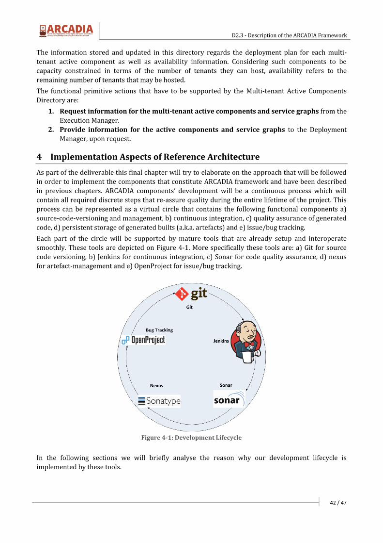
D2.3 - Description of the ARCADIA Framework
42 / 47
The information stored and updated in this directory regards the deployment plan for each multi-
tenant active component as well as availability information. Considering such components to be
capacity constrained in terms of the number of tenants they can host, availability refers to the
remaining number of tenants that may be hosted.
The functional primitive actions that have to be supported by the Multi-tenant Active Components
Directory are:
1. Request information for the multi-tenant active components and service graphs from the
Execution Manager.
2. Provide information for the active components and service graphs to the Deployment
Manager, upon request.
4 Implementation Aspects of Reference Architecture
As part of the deliverable this final chapter will try to elaborate on the approach that will be followed
in order to implement the components that constitute ARCADIA framework and have been described
in previous chapters. ARCADIA components’ development will be a continuous process which will
contain all required discrete steps that re-assure quality during the entire lifetime of the project. This
process can be represented as a virtual circle that contains the following functional components a)
source-code-versioning and management, b) continuous integration, c) quality assurance of generated
code, d) persistent storage of generated builts (a.k.a. artefacts) and e) issue/bug tracking.
Each part of the circle will be supported by mature tools that are already setup and interoperate
smoothly. These tools are depicted on Figure 4-1. More specifically these tools are: a) Git for source
code versioning, b) Jenkins for continuous integration, c) Sonar for code quality assurance, d) nexus
for artefact-management and e) OpenProject for issue/bug tracking.
Figure 4-1: Development Lifecycle
In the following sections we will briefly analyse the reason why our development lifecycle is
implemented by these tools.

D2.3 - Description of the ARCADIA Framework
43 / 47
4.1 Version Control System
A Version Control System (also known as a Revision Control System) is a repository of files, often the
files for the source code of computer programs, with monitored access. Every change made to the
source is tracked, along with who made the change, why they made it, and references to problems
fixed, or enhancements introduced, by the change. Version control systems are essential for any form
of distributed, collaborative development. Whether it is the history of a wiki page or large software
development project, the ability to track each change as it was made, and to reverse changes when
necessary can make all the difference between a well-managed and controlled process and an
uncontrolled 'first come, first served' system. In ARCADIA, the consortium has selected Git as the
primary VCS system. The Git repository is located at https://github.com/UBITECH/ARCADIA and
is access is limited to the consortium developers for the time being. After the finalization of the
project the consortium will open the Git repository which will contain all modules.
4.2 Project organization & Built Automation
The version control system is a crucial part of the ARCADIA development lifecycle. However, one of the
most crucial development aspects that contributes significantly in the quality of the development is
the project organization which relates to the built automation. Build automation is the act of scripting
or automating a wide variety of tasks that software developers do in their day-to-day activities
including:
compiling computer source code into binary code;
packaging binary code;
running tests;
deployment to production systems;
creating documentation and/or release notes.
The term "build automation" now includes managing the pre and post compile and link activities. In
recent years, build management solutions have provided even more relief when it comes to
automating the build process. Both commercial and open source solutions are available to perform
more automated build and workflow processing. Indicative tools include Make16, Ant17, Gradle18 and
Maven19.
Since ARCADIA will rely on Java, Make and Ant are not considered as best-fit candidates. Between
Gradle and Maven, Maven has been selected mainly because of its maturity.
4.3 Continuous Integration
After the formulation of a project which is organized in Maven and managed through Git, the next
challenge of the development lifecycle is Continuous Integration. Continuous Integration is a software
development practice where the members of a team frequently integrate their work – usually each
contributor integrates his software code at least daily, leading to multiple integrations per day. Each
integration cycle is verified by an automated build (including test) to detect integration errors as
quickly as possible. Many teams find that this approach leads to significantly reduced integration
problems and allows a team to develop cohesive software more rapidly. Continuous integration is
16 https://www.gnu.org/software/make
17 https://ant.apache.org
18 http://gradle.org/
19 https://maven.apache.org/
D2.3 - Description of the ARCADIA Framework
44 / 47
achieved through the configuration and usage of a Continuous Integration server (a.k.a. CI server). A CI
server exposes the following set of abilities:
Interoperates with the version control management system (GIT in our case) in order to
trigger a built based on a developer’s commit.
Compiles and launches one or more pre-configured projects based on a triggered event.
Interoperates with code auditing and testing plugins.
Identifies and handles inter-project dependencies.
Perform tasks of publications such as sending mail notification about the progress of the build
process, the result of the builds and test results.
Sends email notification to people who have broken the code.
Prepares summaries and metrics on the build process.
Regarding the CI systems that could be potentially used, the most notable ones are Jenkins20, Hudson21,
TeamCity22 and CruiseControl23. For a project like ARCADIA, the choice of an open source continuous
integration solution is a one-way path, therefore Team City is excluded from the candidate solutions.
Hudson and Jenkins are considered better solutions in comparison with CruiseControl, mainly due to
their flexibility and ease-of-use, with strong and expressive UI enabling all types of operations without
performing any manual XML configuration. Moreover there is a vast community support for both of
these projects. Between these two, Jenkins is the final choice for the reasons presented above
mainly because of its most active community.
4.4 Quality Assurance
Moving clockwise to the development lifecycle, the next step is the quality assurance of the developed
code. As in any technological project in scale, there is a need for a way to measure the quality and how
the work progresses, when different people have different access to pieces of code. Even though
quality is a perceptual, conditional and somewhat subjective attribute and may be understood
differently by different people, software structural quality characteristics have been clearly defined by
the Consortium for IT Software Quality (CISQ), an independent organization founded by the Software
Engineering Institute at Carnegie Mellon University. CISQ has defined 5 major desirable characteristics
of a piece of software needed to provide business. In the “House of Quality” model, these are "What’s"
that need to be achieved:
Reliability: An attribute of resiliency and structural solidity. Reliability measures the level of
risk and the likelihood of potential application failures. It also measures the defects injected
due to modifications made to the software (its “stability” as termed by ISO).
Efficiency: The source code and software architecture attributes are the elements that ensure
high performance once the application is in run-time mode. Efficiency is especially important
for applications in high execution speed environments such as algorithmic or transactional
processing where performance and scalability are paramount.
Security: A measure of the likelihood of potential security breaches due to poor coding
practices and architecture. This quantifies the risk of encountering critical vulnerabilities that
damage the business.
20 http://jenkins-ci.org
21 http://hudson-ci.org
22 https://www.jetbrains.com/teamcity
23 http://cruisecontrol.sourceforge.net/
D2.3 - Description of the ARCADIA Framework
45 / 47
Maintainability: Maintainability includes the notion of adaptability, portability and
transferability (from one development team to another). Measuring and monitoring
maintainability is a must for mission-critical applications where change is driven by tight time-
to-market schedules and where it is important for IT to remain responsive to business-driven
changes. It is also essential to keep maintenance costs under control.
Size: While not a quality attribute per se, the sizing of source code is a software characteristic
that obviously impacts maintainability.
ARCADIA will rely on Sonar in order to perform analysis of code quality. Sonar is an open source
software quality platform. Sonar uses various static code analysis tools such as CheckStyle24, to extract
software metrics, which then can be used to improve software quality. Sonar offers reports on
duplicated code, coding standards, unit tests, code coverage, complex code, potential bugs, comments,
design and architecture. The primary supported language is Java - other languages are supported with
extensions. Today, several open source and commercial extensions can cover the following languages:
C, C#, PHP, Flex, Groovy, JavaScript, Python, PL/SQL, COBOL and Visual Basic 6. It integrates with
Maven, Ant and continuous integration tools and is expandable with the use of plugins.
4.5 Release Planning
The next step in the development lifecycle is the release planning. Release planning includes also
repository management. The release management in the ARCADIA project will be accomplished
with the help of Nexus Release Management. The release management is tightly connected with the
selected branching model. In the frame of ARCADIA the Git branching model will be followed. The aim
of the introduction of different branches is to ensure the quality of the resulting source code and to
decrease the number of failures. Starting with a master branch this is parted into a developing branch,
a release branch and a possibly existing Hotfix-branch. Furthermore, separate branches are created
per implemented feature. Upon the completion of each feature the feature branch is merged in the
development branch. The development branch is used as a basis for the official release management.
Each commit that is performed in the development branch reflects to one binary that is hosted in the
Nexus. Official releases will be also hosted in Nexus with a descriptive tag.
4.6 Issue tracking
The last step of the development lifecycle is the issue/bug tracking. Independent on how carefully and
detailed the software is tested before the productive release; during the usage by the end-users, bugs
and problems will occur. Therefore, it is necessary to operate an issue/bug tracking system. An issue
tracker that is reachable for every developing partner needs to be included to collect development
time issues like problem reports, feature requests, and work assignments. In the frame of ARCADIA,
for issues concerning coding, features and distribution, the GitHub issue tracker is chosen while
OpenProject is applied to provide support for external users.
Both the internal and external issue reporting processes is implemented in way that is depicted on
Figure 4-2. When an end-user or an ARCADIA developer recognizes a problem or a missing feature
she/he reports the bug or issue. The reporting is typically done by creating a new issue via the front
end of the issue/bug tracker. The newly created issue is picked by the responsible ARCADIA
developer. A notification mechanism, usually implemented using email, notifies the assignee about
created issues and updates. The developer starts working on the ticket and documents the progress.
24 http://checkstyle.sourceforge.net
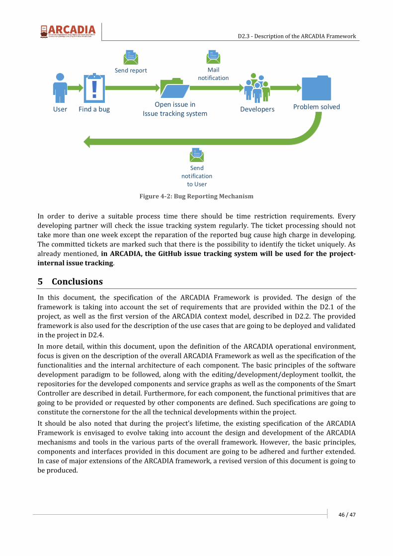
D2.3 - Description of the ARCADIA Framework
46 / 47
User Find a bug DevelopersOpen issue in
Issue tracking systemProblem solved
Mail notification
Send notification
to User
Send report
Figure 4-2: Bug Reporting Mechanism
In order to derive a suitable process time there should be time restriction requirements. Every
developing partner will check the issue tracking system regularly. The ticket processing should not
take more than one week except the reparation of the reported bug cause high charge in developing.
The committed tickets are marked such that there is the possibility to identify the ticket uniquely. As
already mentioned, in ARCADIA, the GitHub issue tracking system will be used for the project-
internal issue tracking.
5 Conclusions
In this document, the specification of the ARCADIA Framework is provided. The design of the
framework is taking into account the set of requirements that are provided within the D2.1 of the
project, as well as the first version of the ARCADIA context model, described in D2.2. The provided
framework is also used for the description of the use cases that are going to be deployed and validated
in the project in D2.4.
In more detail, within this document, upon the definition of the ARCADIA operational environment,
focus is given on the description of the overall ARCADIA Framework as well as the specification of the
functionalities and the internal architecture of each component. The basic principles of the software
development paradigm to be followed, along with the editing/development/deployment toolkit, the
repositories for the developed components and service graphs as well as the components of the Smart
Controller are described in detail. Furthermore, for each component, the functional primitives that are
going to be provided or requested by other components are defined. Such specifications are going to
constitute the cornerstone for the all the technical developments within the project.
It should be also noted that during the project’s lifetime, the existing specification of the ARCADIA
Framework is envisaged to evolve taking into account the design and development of the ARCADIA
mechanisms and tools in the various parts of the overall framework. However, the basic principles,
components and interfaces provided in this document are going to be adhered and further extended.
In case of major extensions of the ARCADIA framework, a revised version of this document is going to
be produced.

D2.3 - Description of the ARCADIA Framework
47 / 47
Annex I: References
[1] Internet Draft: Policy Architecture and Framework for NFV Infrastructures, NFV Research Group
[2] ARCADIA Project – Deliverable 2.1: Description of Highly Distributed Applications and Programmable Infrastructure Requirements
[3] ARCADIA Project – Deliverable 2.2: Definition of the ARCADIA context model
Top Related