


![Code No: PRESTRESSED CONCRETE BITSVIZAG/BITS/EXAM CELL/q...PART±A (22 Marks) 1. a) What is pretensioning and post-tensioning? [4] b) What is pressure line? Explain its significance.](https://static.fdocuments.in/doc/165x107/5ab28ad07f8b9ac3348d67c0/code-no-prestressed-concrete-bitsvizagbitsexam-cellqparta-22-marks-1-a.jpg)

Languages
Pages
Legal


A Novel Concept of Pretensioning
Prestressed Concrete Pavements
by Lev Zetlin
Reprinted from the copyrighted Journal of the Prestressed Concrete Institute Vol. 6, No.1 March, 1961

PROCEEDINGS PAPER
A Novel Concept of Pretensioning
Prestressed Concrete Pavements
Presented at the Prestressed Concrete Institute Convention New York City, September 28, 1960
by Lev Zetlin*
Prestressing concrete in buildings and bridges is an estabushed and continuously expanding practice. It is only natural to extend prestressing to runways and highways to overcome the ever present problem of the cracking of conventional concrete pavement.
The superiority of a prestressed over a conventional reinforced concrete pavement is obvious: savings in quantity of concrete (the thickness of a prestressed pavement is but a fraction of that of a conventional concrete pavement), resilience of a prestressed pavement and, hence, less stringent requirements for the preparation of subgrade; and, finally, the most important characteristic of prestressed pavement is the absence of shrinkage and thermal cracks and, therefore, negligible maintenance during the service life of the pavement. As prestressed concrete bridges became a nationwide practice within the span of a few years from scattered pioneering attempts, so it would not be surprising to witness a nationwide network of prestressed highways within the foreseeable future.
In prestressed concrete, as commonly employed in buildings and bridges, we usually regard the structural behavior under service loads
"Ph.D. P.E. Consulting Engineer New York City
March, 1961
of post-tensioned concrete on a par with that of pretensioned concrete. The choice between pretensioning and post-tensioning is essentially based upon the economy of imparting the prestress. \Ve are soon to see that this concept does not exactly hold for prestressed pavement.
A pavement differs from an edge supported slab (such as a floor slab) in that the pavement is supported on a subgrade over its entire area, while an edge supported slab is supported only along its edges. This continuous subgrade support, in addition to developing vertical reactions when vertical loads are appued to the pavement, also develops horizontal frictional forces at the bottom surface of the pavement, when the latter is subjected to horizontal strains in its plane due to volumetric changes which might be thermal, shrinkage or creep. Because of these vertical and horizontal subgrade reactions, the structural behavior of the pavement and its resistance to applied loads and volumetric changes is greatly influenced by whether the pavement is pretensioned or post-tensioned; because in pretensioning the strand has a potential continuous bond with concrete.
In an edge supported slab, the prestressing stress may be assumed as constant throughout the slab, as shown in Fig. 1 ( a ). On the other hand, in a pavement, because of the
93

I
I
p
':;L __ <': .,- ~.~ ·I'; ~; .r :~~·.. r;~ : !l..~: ;\" I;
( f· friction forcQ
t.y;
PCl Journal 94

friction developed by the subgrade on the bottom surface of the pavement, the magnitude of prestressing stress at every point throughout the pavement can not be predictedaccurately. All we actually know is the magnitude of the force which is applied at the anchorage at the edge of the pavement. Since there is always some amount of friction between the pavement and subgrade, the residual prestress in the pavement can be approximated by a curve as shown in Fig. 1 (b ) . This diagram would be the same for either post-tensioned or pretensioned pavements.
To illustrate the eHect of pretensioning on a pavement, let us consider the two cases in Fig. 2. Fig. 2( a) shows a prestressed slab supported along its edges; Fig. 2( b) shows a pretensioned pavement. Let's suppose that each of these two cases represents a prestressed slab after the elastic strains due to prestressing have taken place and the slabs have been put into service. Let us look into deformations when each of the slabs is subjected to concentrated load at some point in its interior portion.
The suspended floor slab in Fig. 2( a) under the action of the concentrated load has a continuous curvature. The prestressing forces are acting at the edges of the slab whether the prestressing has been applied by post-tensioning or by pretensioning.
However, because of subgrade reaction and friction, the concentrated load, Fig. 2(b), would cause local distortions of the pavement in the immediate vicinity of the concentrated load. This is obvious if we consider a pavement as a plate on a continuous elastic support. Due to the frictional forces there will be a still greater tendency for the localization of distortions.
March, 1961 .
Under the concentrated load in the interior portion of a pretensioned pavement, localized bond stresses would be set up in the pretensioned strands, as is shown in Fig. 2 (b). These bond stresses create, in eHect, an independently prestressed element inside the pretensioned pavement. This is an important contribution of pretensioning-namely, the potentiality of developing reliable bond resistence at any point in the pavement. There is also an advantage in pretensioning pavement with respect to its resistence to volumetric changes.
Additional advantages of pretensioning in pavements are:
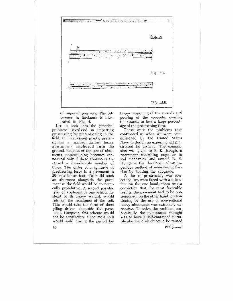
1. Invulnerability to damage. If a portion of the pavement-including the edge of the slab where bond stresses are initially concentrated-is for some reason destroyed, the pretensioning strands would develop reliable bond stresses in the remaining portions of the pavement, as is shown in Fig. 3.
2. Thickness of pavement may be reduced when pretensioning is employed. In post-tensioned pavement, the tendons should be spread as far apart as possible to strike a balance between structural behavior and economy and, hence, are usually over 1 in. in diameter. Since most pavements require criss-crossing of tendons, the thickness of the pavement is usually dictated by the depth of the two layers of tendons, although from a purely structural consideration, a thinner pavement would be feasible. With pretensioning it is possible to use more closely spaced, thinner strands, say 5/16 in. in diameter. This, in turn, results in a thinner pavement as well as in a more favorable distribution
95
i . , ;,' ,::tIl
, . '. 3 .. .... ,', '. "
@'.' . ", ' , ' '.', ,(i) ' . . , \ . . , '. .
fig. 4a.
, ' . , :: ' ' ~.:: " . :. Ir'J : "" :
..
of imposed prestress. The difference in thickness is illustrated in Fig. 4.
Let us look into the practical problems involved in imparting prestr essing by pretensioning in the field. In 11 restressing plants, pretensionmg II applied against heavy abu t m en t 5 a n chored in to the ground. Because of the cost of abutments, pl'~tensioning becomes economical only if these abutments are reused a considerable number of times. The order of magnitude of prestressing force in a pavement is 20 kips linear foot. To build such an abutment alongside the pavement in the field would be economically prohibitive. A second possible type of abutment is one which, instead of its heavy weight, would rely on the resistance of the soil. This would take the form of sheet piling driven alongside the pavement. However, this scheme would not , be satisfactory since most soils would yield during the period be
96
tween tensioning of the strands and pouring of the concrete, causing the strands to lose a large percentage of the prestressing force.
These were the problems that confronted us when we were commissioned by the United States Navy to design an experimental prestressed jet taxiway. The commission was given to B. K. Hough, a prominent consulting engineer in soil mechanics, and myself. B. K. Hough is the developer of an ingenious method of overcoming friction by Boating the subgrade.
As far as prestressing was concerned, we were faced with a dilemrna: on the one hand, there was a conviction that, for most favorable results, the pavement had to be pretensioned; on the other hand, pretensioning by the use of conventional heavy abutrrwpts was extremely expensive. To solve the problem economically, the spontaneous thought was , to have a self-contained portable abutment which could be reused
pel Journal
f 18 5 <1
tenslona:d ~trand
March, 1961 97

Portable abutments form closed ring which is dimensionally stabilized by auxiliary tension cables.
Fig. 6a
an unlimited number of times. Because of the large forces involved, this seemed like wishful thinking at the time. However, further insight into the problem revealed to the surprise of everybody associated with the study that such an abutment was within the realm of possibility. As a matter of fact, the portable abutment to be described next, emerged as an economical means for prestressing not only airfields, but also highway pavements. Furthermore, conventional pavement equipment could be used in conjunction with the portable abutment.
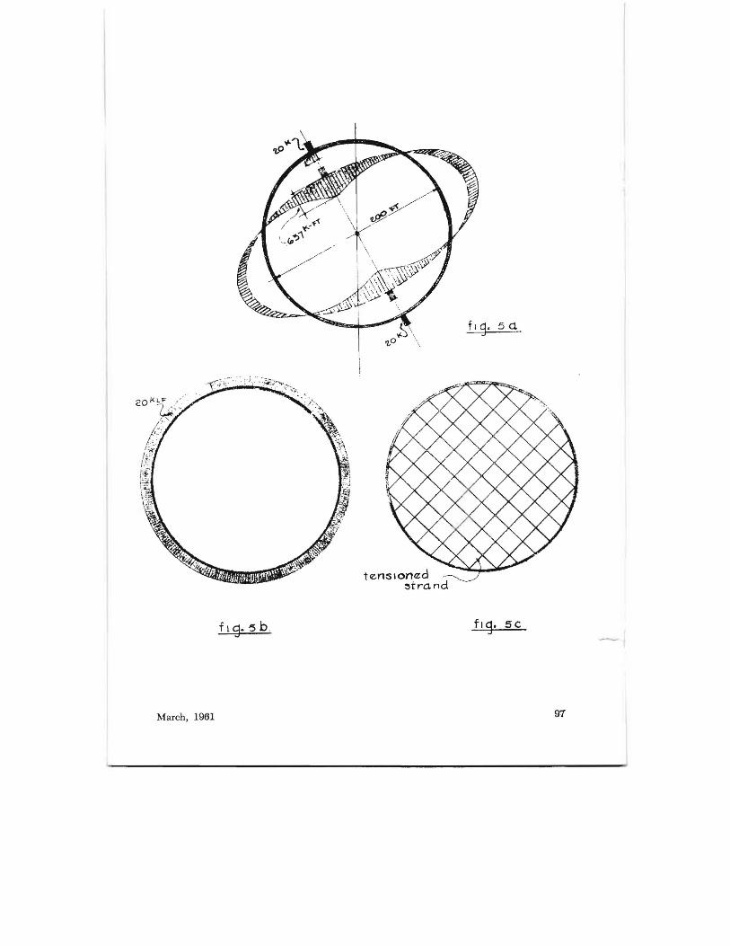
The interesting feature of the abutment is that it 0 d erives its strength from the very strands used for prestressing the pavement .
The abutment is based on the simple principle of a closed curve, such as a ring, as shown in Fig. 5 ( a ). The ring, if subjected to a pair of forces acting across its diagonal, would be extremely flexible, and large bending moments would be set up in it . For example, a 200 ft. dia. ring, subjected to two diametrically opposed forces of 20 kips each distributed over one foot of periphery, would have a maximum
98
bending moment of 637 kips X ft ., requiring 70 sq. inches in cross-sectional area of structural steel. On the other hand, if this ring were subjected to hydrostatic pressure of 20 kips per foot over the entire perimeter, as in Fig. 5( b), no bending moments would be set up, but the entire ring would be in compression, with a compressive force of 2000 kips, requiring 100 sq. inches in a cross-sectional area of structural steel for a total force of 12,560 kips as compared with 70 sq. inches in Fig. 5 ( a ), for a total force of 40 kips.
A state equivalent to hydrostatic compression could be achieved if the ring is criss-crossed by strands in tension, as in Fig. 5( c). Crisscrossing of strands has an additional important advantage in that a ring tied by strands does not buckle in its plane.
The portable abutment that we have developed and shown in Fig. 6 is essentially a closed curve, but instead of being a circular ring it has an oval shape. This shape has been adopted since it is more efficient for pavements. In pavements, the required longitudinal prestress
!
$UTIl1TITI", 't. of Groups of Strands (b)
I:::' o -
F!,
~. 1L.!i:L..c
p-
Groups of pretensioned prestressin1:rands are held in take-up assemblies attached to a tment.
Fig.6b
PCl Journal

is usually higher than the required transverse prestress. Hence, the oval shape.
Figure 6 shows half of the assembled abutment in place. The 'abutment shown meaS.UTes 200 ft. x 70 ft., and is composed of assembled elements 10 ft. long each. Fig. 6(b) shows the main prestressing strands. This configuration may be adjusted so that the entire abutment is only in compression. To make sure that the abutment is entirely in compression, as well as to eliminate buckling of the abutment out of its plane, a grid of auxiliary cables, as shown in Fig. 6( a), is attached to the underside of the abutment.
The abutment itself is built of short portable elements, as shown in Fig. 7. This figure shows, also, some cross-sections. In this case the abutments consist of high strength steel channels separated by timber blocking. The separate elements are placed on the ground to form a closed curve as required.
The pretensioning strands in this scheme are in clusters. Each cluster is anchored to a movable anchorage
block. Each block has studs passing through the abutment. Jacks grab the studs and pull the blocks with the strands by pushing against the abutment.
When the strands are tensionedat which point the whole assembly looks like a snow shoe or a tennis racket-the pavement is poured with conventional paving equipment. The poured pavement is shown in Fig. 8.
When the pavement has hardened sufficiently, the prestressing
, strands are burned ofF and the abutment is ready to be taken apart and. moved to another section. The auxiliary strands, which are insignificant relative to the prestressing strands, are left in piace, unstressed, under the pavement.
With the portable abutmenl , the pavement is cast in sections. For example, the sections into whicL J e jet taxiway for thE; Navy has 'Jtf!ll
subdivided is shown in Fig. R 1 his particular pavement was about 2..t;"0 ft. long, one portion of which \ .1S
50 ft. wide and the other, 150 (t.
wide. Each section is apprOXimately 150 ft. by 50 ft. In a long paveme t,
Section d-d Showino Anchorooe
1 If - - --1 :~ .~ ~ ~~§f'H : H~ij; ____! ~~~
I I Seclion c-c For Longiludinal Strands Strand'S Section bob ShowlnQ Curb Splice
Details 0/ portable abutment designed faT lise on preterlSioned, prestressed pavement projects.
Seclion c - c For Transverse
Fig. 7
March, 1961 99
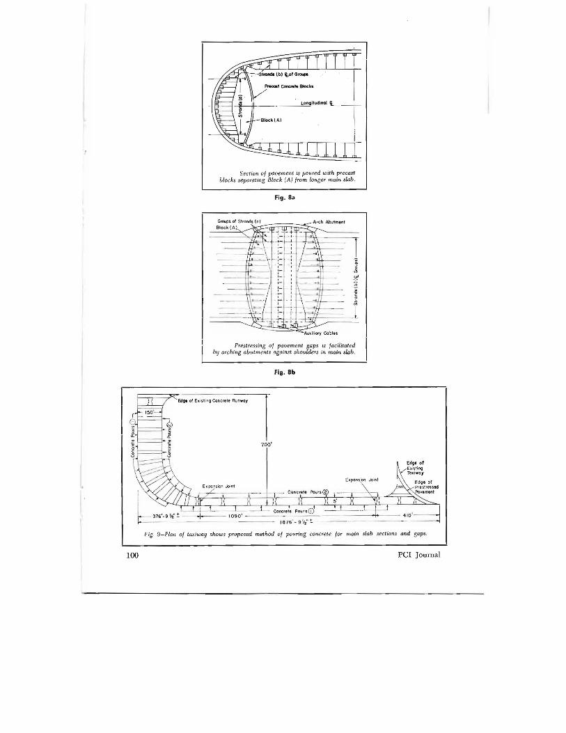
Sect ion of pavem ent is poured with precast blocks separating Block (AJ from longer main slab .
Fig.8a
Prestressing of pavement gaps is facilitated by arching abutments against shoulders in main slab .
Fig.8b
1876' - 91/z"!:' - ---
Fig . 9-Plan of taxiway shows proposed method of pouring concrete for main slab sections and gaps.
100 pcr Journal

a practical method would be to have available four abutments to be placed consecutively along the pavement to be poured. Paving would then become a continuous operation: as the paver reaches, let's say, the fourth section, the first abutment has been released from the first section and erected in front of the fourth section which is being paved. When the paver is through paving the fourth section, it is ready to move ahead to the fifth section where the first abutment had been placed and where the strands have. already been prestressed.-And so on in a caterpillar pattern.
The next major step is to create a continuous prestressed pavement through the gaps so as to end up with a continuous pavement of the desired length. In the jet taxiway shown previously, for example, the length of pavement between expansion joints was about 1100 ft. To bring about continuous prestress requires prestressing of the gaps but, at the same time, this must be done without disturbing the previously imposed prestress in each individual main section.
The continuous prestressing through the gaps is accomplished as follows: (Fig. 8b ) After the main strands have been tensioned, but before the main section has been poured, precast concrete blocks which are lined with paper so that they can be removed easily later on, are inserted at each end of the pavement. The end portion of the pavement between the gap and the precast blocks-which we shall call Block "A"-has embedded in it, in addition to the main prestressing strands crossing through it to the abutment, another set of prestressing strands called Strands "a", except that these additional strands are left loose when the main concrete section is poured. After the concrete
March, 1961
in the main sections has hardened, there is left a gap between consecutive main sections. Each side of the gap is bordered by Blocks "A" with loose longitudinal strands "a" anchored in each one of them and extending into the gap. By taking a few elements of the standard abutment and placing them against the previously poured hardened main sections of the pavement, transverse strands are strung through the gap and attached to the abutment. Longitudinal strands "a", in turn, are connected t9gether by a standard unit. By stretching the transverse strands against the abutment, and by laterally stretching apart the longitudinal strands "a" (as in "harping" strands in precasting plants) , the entire grid of strands in the gap is thereby prestressed. As transverse and longitudinal strands in the gap are stretched, abutments exert pressure against the main sectic.c;s of the pavement. Blocks "A"-in which strands "a" are embedded-tend to move towards the gap, relieving pressure from the precast blocks. The abutments, together with the ends of the main sections, form actually a structural ring reinforced by transverse strands and longitudinal strands "a". The abutments are in compression. The reaction in the longitudinal direction of the abutments on the main sections is equal to the sum of all tensions of the longitudinal strands of the main section. Thus, the previous state of prestress in the main section has not been disturbed.
At this stage, the precast blocks are removed and both the gap and the grooves left by the precast blocks are concreted. When this concrete hardens, the strands are burned off the abutment and the abutments removed, creating a continuous prestressed pavement.
There are also other important ap
101

plications of the portable abutment. It does not require too much imag
ination to see the many potential uses of this portable abutment in precasting plants, particularly, for two-way prestressing of either rectangular or irregularly shaped slabs.
One example is shown in Fig. 10 which represents a two-way prestressing of a precast 80' high fin for a stadium. It is interesting to note that more than one slab could be prefabricated at the same time
within the same abutment if the abutment is made big enough to contain them all.
The method described previously lends itself to plant precasting of long girders of, say, over 100' in Jength. These girders are too long to be transported conveniently. However, following the same procedure as was illustrated for pavements, they may be prefabricated in shorter pieces, transported to the construction site, and connected together.
,~~~ r Tr T ,
b-l.--L..--In'~.
- f-===
~ --......:::::: Q....., "-ItwJ.. ~I
Fig. 10-Within closed ring of portable abutments alnwst any shape desired could be poured. System can be utilized in precast operations or on job site.
102 PCl Journal
Top Related