


Languages
Pages
Legal


A low cost sEMG controlled robotic hand for
amputees Student name: Ilan Eskinazi
Robot’s name: Marey’s hand Intelligent machine design lab
(EEL5666C)
Instructors: Dr. A. Antonio Arroyo
Dr. Eric M. Schwartz
TAs : Tim Martin and Josh Weaver

2
Table of Contents Abstract ............................................................................................................................... 3
Executive Summary ............................................................................................................ 3
Introduction ......................................................................................................................... 3
Integrated system ................................................................................................................ 3
CAD model overview ..................................................................................................... 3
Mobile Platform .................................................................................................................. 5
Hand mechanics .............................................................................................................. 5
Attachments to arm ......................................................................................................... 5
Materials used ................................................................................................................. 5
Actuation ............................................................................................................................. 6
Sensors ................................................................................................................................ 6
Surface EMG sensors ...................................................................................................... 6
Principles of operation ................................................................................................ 6
Rationale behind EMG sensor use .............................................................................. 6
EMG sensor design ..................................................................................................... 7
Instrumentation necessary ........................................................................................... 8
EMG signal processing ................................................................................................... 8
Force sensors ................................................................................................................... 8
Behaviors ............................................................................................................................ 8
How to control the robot ................................................................................................. 9
Cost ................................................................................................................................... 10
Code structure ................................................................................................................... 10
Conclusion ........................................................................................................................ 12
Documentation .................................................................................................................. 12
References ......................................................................................................................... 24

3
Abstract Amputees who have undergone a wrist disarticulation often use an artificial hand or hook
prosthesis to regain part of the lost function. However, advanced robotic prostheses
remain economically out of reach of many patients. This project proves that a low cost
surface EMG controlled prosthetic hand can be built and be fully operational. A special
EMG sensor with dry electrodes was developed, together with a hand mechanism
actuated by servo-motors. Force sensitive resistors were placed on the palm of the
artificial hand to provide some level of feedback and allow for soft gripping. The whole
machine is controlled with an Arduino Mega 2560 board clone. The cost of materials is
less than $200.
Executive Summary A robotic prosthetic hand was constructed. It utilizes surface EMG from the user’s
forearm as its control signals. Each finger can be extended and flexed independently. A
force feedback mode allows the hand to operate in a “soft-grip” mode.
Introduction This project explores the possibility of constructing a low-cost prosthetic hand for
amputees that can be controlled with surface electromyography. Surface
electromyography (sEMG) is a sensing technique that allows the capture of action
potentials of muscles during activation. Most advanced prosthetic hands found in the
market provide great capabilities but come at a steep cost (reaching up to $35,000 for the
bebionic hand [1]) making it virtually inaccessible to a large number of people who could
benefit from it, especially in underdeveloped countries.
The robotic hand was constructed using servo-motors for actuation, and custom-made
EMG sensors. Additional components include an LCD screen, two buttons, and two
force-sensitive resistors (FSRs). After three months of development, the machine
operates properly.
Integrated system
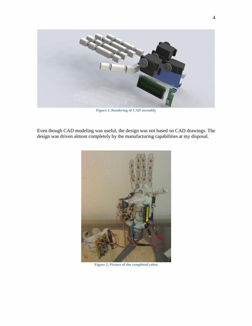
CAD model overview The use of Solidworks to model and display several components of the prosthetic
assembly facilitated some design choices, e.g. placement of the servomotors in their final
configurations. This saved time and money since it became possible to verify if there was
interference between the different components.
4
Figure 1. Rendering of CAD assembly
Even though CAD modeling was useful, the design was not based on CAD drawings. The
design was driven almost completely by the manufacturing capabilities at my disposal.
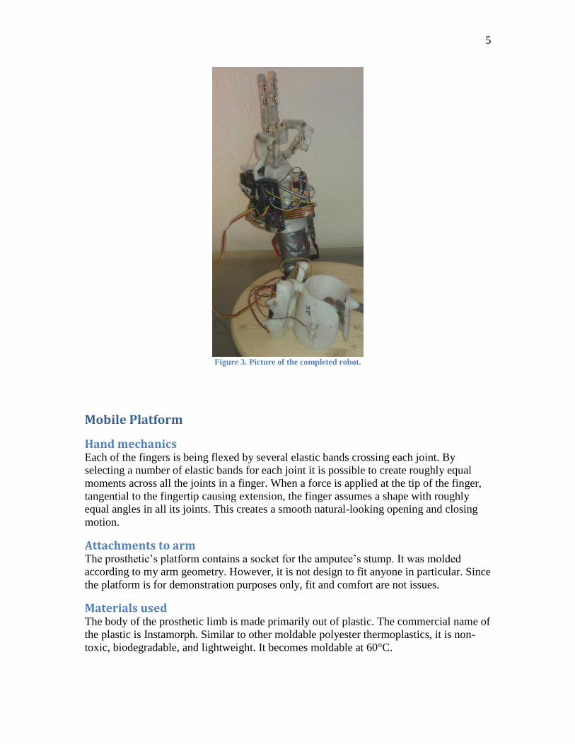
Figure 2. Picture of the completed robot
5
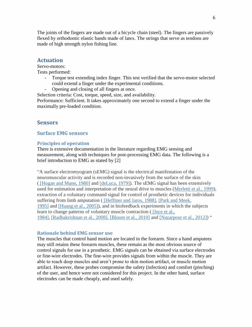
Figure 3. Picture of the completed robot.
Mobile Platform
Hand mechanics Each of the fingers is being flexed by several elastic bands crossing each joint. By
selecting a number of elastic bands for each joint it is possible to create roughly equal
moments across all the joints in a finger. When a force is applied at the tip of the finger,
tangential to the fingertip causing extension, the finger assumes a shape with roughly
equal angles in all its joints. This creates a smooth natural-looking opening and closing
motion.
Attachments to arm The prosthetic’s platform contains a socket for the amputee’s stump. It was molded
according to my arm geometry. However, it is not design to fit anyone in particular. Since
the platform is for demonstration purposes only, fit and comfort are not issues.
Materials used The body of the prosthetic limb is made primarily out of plastic. The commercial name of
the plastic is Instamorph. Similar to other moldable polyester thermoplastics, it is non-
toxic, biodegradable, and lightweight. It becomes moldable at 60°C.
6
The joints of the fingers are made out of a bicycle chain (steel). The fingers are passively
flexed by orthodontic elastic bands made of latex. The strings that serve as tendons are
made of high strength nylon fishing line.
Actuation Servo-motors:
Tests performed:
- Torque test extending index finger. This test verified that the servo-motor selected
could extend a finger under the experimental conditions.
- Opening and closing of all fingers at once.
Selection criteria: Cost, torque, speed, size, and availability.
Performance: Sufficient. It takes approximately one second to extend a finger under the
maximally pre-loaded condition.
Sensors
Surface EMG sensors
Principles of operation There is extensive documentation in the literature regarding EMG sensing and
measurement, along with techniques for post-processing EMG data. The following is a
brief introduction to EMG as stated by [2]
“A surface electromyogram (sEMG) signal is the electrical manifestation of the
neuromuscular activity and is recorded non-invasively from the surface of the skin
( [Hogan and Mann, 1980] and [deLuca, 1979]). The sEMG signal has been extensively
used for estimation and interpretation of the neural drive to muscles (Merletti et al., 1999),
extraction of a voluntary command signal for control of prosthetic devices for individuals
suffering from limb amputation ( [Hefftner and Jaros, 1988], [Park and Meek,
1995] and [Huang et al., 2005]), and in biofeedback experiments in which the subjects
learn to change patterns of voluntary muscle contraction ( [Ince et al.,
1984], [Radhakrishnan et al., 2008], [Bloom et al., 2010] and [Nazarpour et al., 2012]) “
Rationale behind EMG sensor use The muscles that control hand motion are located in the forearm. Since a hand amputees
may still retains these forearm muscles, these remain as the most obvious source of
control signals for use in a prosthetic. EMG signals can be obtained via surface electrodes
or fine-wire electrodes. The fine-wire provides signals from within the muscle. They are
able to reach deep muscles and aren’t prone to skin motion artifact, or muscle motion
artifact. However, these probes compromise the safety (infection) and comfort (pinching)
of the user, and hence were not considered for this project. In the other hand, surface
electrodes can be made cheaply, and used safely.
7
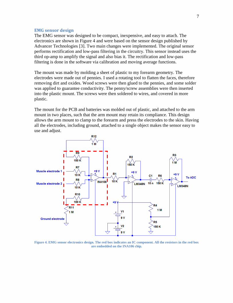
EMG sensor design The EMG sensor was designed to be compact, inexpensive, and easy to attach. The
electronics are shown in Figure 4 and were based on the sensor design published by
Advancer Technologies [3]. Two main changes were implemented. The original sensor
performs rectification and low-pass filtering in the circuitry. This sensor instead uses the
third op-amp to amplify the signal and also bias it. The rectification and low-pass
filtering is done in the software via calibration and moving average functions.
The mount was made by molding a sheet of plastic to my forearm geometry. The
electrodes were made out of pennies. I used a rotating tool to flatten the faces, therefore
removing dirt and oxides. Wood screws were then glued to the pennies, and some solder
was applied to guarantee conductivity. The penny/screw assemblies were then inserted
into the plastic mount. The screws were then soldered to wires, and covered in more
plastic.
The mount for the PCB and batteries was molded out of plastic, and attached to the arm
mount in two places, such that the arm mount may retain its compliance. This design
allows the arm mount to clamp to the forearm and press the electrodes to the skin. Having
all the electrodes, including ground, attached to a single object makes the sensor easy to
use and adjust.
Figure 4. EMG sensor electronics design. The red box indicates an IC component. All the resistors in the red box
are embedded on the INA106 chip.
8
Instrumentation necessary In order to verify the behavior of the sensor, I used a program that turns a laptop’s sound
card into an oscilloscope. This proved crucial since it allowed me to observe and capture
sEGM signals at home. I later used the Arduino board itself and 3rd
party software
(Processing, Parallax DAQ, and Excel) to plot the analog signal.
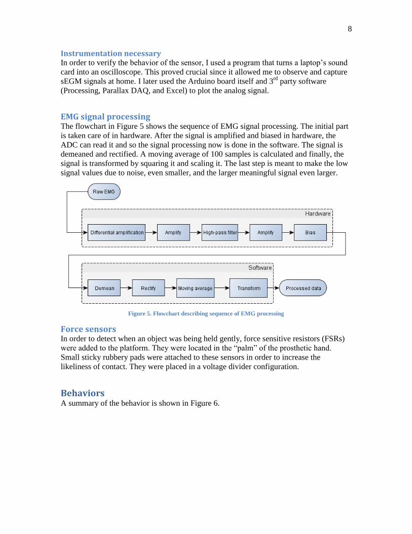
EMG signal processing The flowchart in Figure 5 shows the sequence of EMG signal processing. The initial part
is taken care of in hardware. After the signal is amplified and biased in hardware, the
ADC can read it and so the signal processing now is done in the software. The signal is
demeaned and rectified. A moving average of 100 samples is calculated and finally, the
signal is transformed by squaring it and scaling it. The last step is meant to make the low
signal values due to noise, even smaller, and the larger meaningful signal even larger.
Figure 5. Flowchart describing sequence of EMG processing
Force sensors In order to detect when an object was being held gently, force sensitive resistors (FSRs)
were added to the platform. They were located in the “palm” of the prosthetic hand.
Small sticky rubbery pads were attached to these sensors in order to increase the
likeliness of contact. They were placed in a voltage divider configuration.
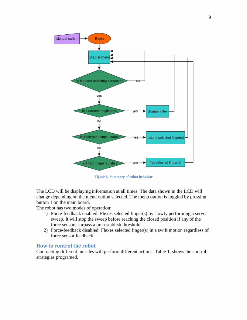
Behaviors A summary of the behavior is shown in Figure 6.
9
Figure 6. Summary of robot behavior
The LCD will be displaying information at all times. The data shown in the LCD will
change depending on the menu option selected. The menu option is toggled by pressing
button 1 on the main board.
The robot has two modes of operation:
1) Force-feedback enabled: Flexes selected finger(s) by slowly performing a servo
sweep. It will stop the sweep before reaching the closed position if any of the
force sensors surpass a pre-establish threshold.
2) Force-feedback disabled: Flexes selected finger(s) in a swift motion regardless of
force sensor feedback.
How to control the robot Contracting different muscles will perform different actions. Table 1, shows the control
strategies programed.
10
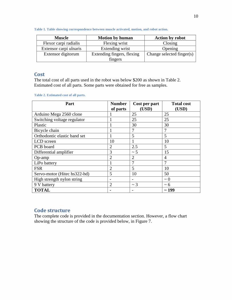
Table 1. Table showing correspondence between muscle activated, motion, and robot action.
Muscle Motion by human Action by robot
Flexor carpi radialis Flexing wrist Closing
Extensor carpi ulnaris Extending wrist Opening
Extensor digitorum Extending fingers, flexing
fingers
Change selected finger(s)
Cost The total cost of all parts used in the robot was below $200 as shown in Table 2.
Estimated cost of all parts. Some parts were obtained for free as samples.
Table 2. Estimated cost of all parts.
Part Number
of parts
Cost per part
(USD)
Total cost
(USD)
Arduino Mega 2560 clone 1 25 25
Switching voltage regulator 1 25 25
Plastic 1 30 30
Bicycle chain 1 7 7
Orthodontic elastic band set 1 5 5
LCD screen 10 1 10
PCB board 2 2.5 5
Differential amplifier 3 ~ 5 15
Op-amp 2 2 4
LiPo battery 1 7 7
FSR 2 5 10
Servo-motor (Hitec hs322-hd) 5 10 50
High strength nylon string - - ~ 0
9 V battery 2 ~ 3 ~ 6
TOTAL - - ~ 199
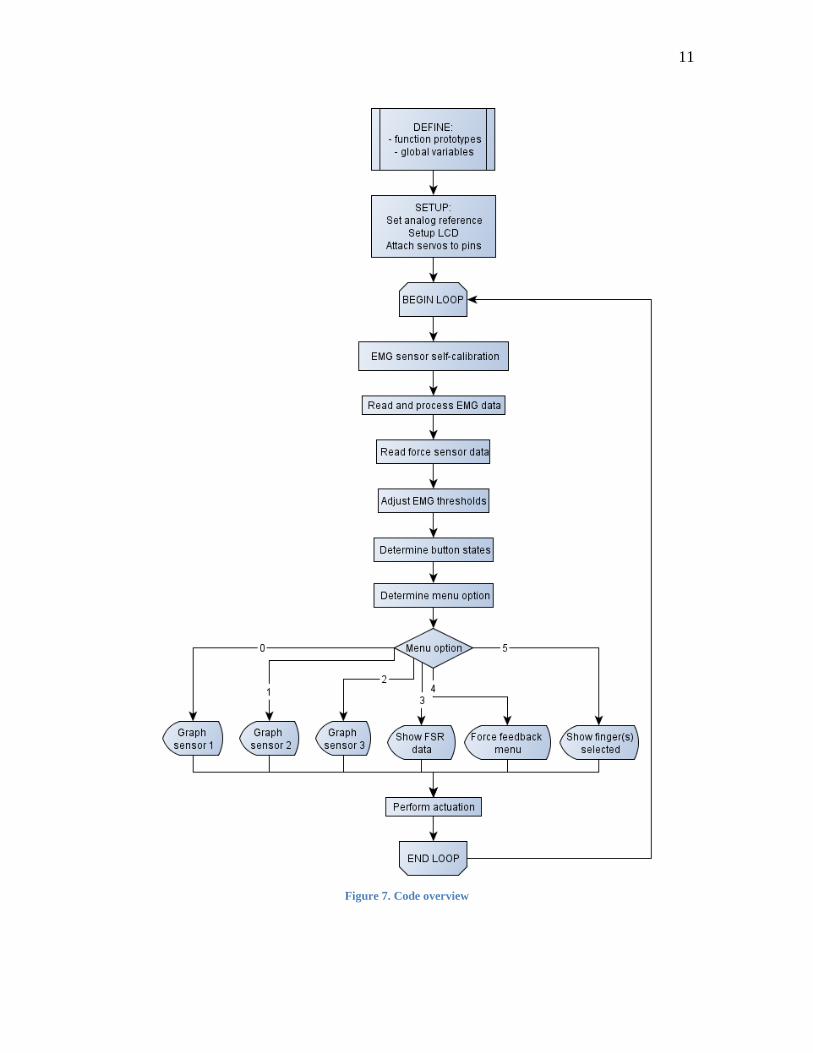
Code structure The complete code is provided in the documentation section. However, a flow chart
showing the structure of the code is provided below, in Figure 7.
11
Figure 7. Code overview

12
Conclusion A working prototype was obtained. It is responsive to muscle activations and allows for
grasping of different objects. Thus, it has been shown that the technology to create a low-
cost sEMG-controlled robotic hand prosthesis is readily available.
Documentation
The following is the final version of the code:
#include <LiquidCrystal.h>
#include <LcdBarGraph.h>
#include <Servo.h>
// function prototypes
int process_EMG(int rawEMG, int signal[], int &smin);
void calibrate();
void setButton1State();
void setButton2State();
void graphSensor(int sensorNumber);
void hand_open();
void hand_close();
void set_threshold(int smin, int &st);
void set_threshold_index(int smin, int &st);
void reg_open();
void reg_close();
void forceFB_close();
void sweep_servo(Servo &myServo, int flex_angle, int ext_angle);
void sweep_ALL_servos();
// Servos
Servo finger1; // thumb, PWM 10
Servo finger2; // index, PWM 12
Servo finger3; // middle, PWM 13
Servo finger4; // ring, PWM 9
Servo finger5; // pinky, PWM 11
int flex_a1 = 10;
int flex_a2 = 0;
int flex_a3 = 180;
int flex_a4 = 0;
int flex_a5 = 180;
int ext_a1 = 180;
int ext_a2 = 130;
int ext_a3 = 25;
int ext_a4 = 115;
int ext_a5 = 70;

13
int PosSweepDelay = 15; // 15ms to delay each position for sweeping a servo
long timeOfLastSweep = 0;
int timeBetweenSweeps = 1000; // 1 second "delay" between sweeps
// LCD setup
byte lcdNumCols = 16; // -- number of columns in the LCD
LiquidCrystal lcd(7, 6, 5, 4, 3, 2); // -- creating LCD instance
LcdBarGraph lbg(&lcd, lcdNumCols); // -- creating
const int graphMax = 100; // maximum value to graph
// calibration
int calibSignal = 0; // signal to gather sensor 1 data and calibrate
int calibSize = 300; // how many data points are used to obtain average
float calibSum = 0; // sum of all measurements
int calibCount = 0; // how many times you have added measurements
int cal = 428; // calibration value
// EMG sensors
const int filterSize = 100;
int signal_1[filterSize] = {
0};
int signal_2[filterSize] = {
0};
int signal_3[filterSize] = {
0};
int sensorVal_1 = 0;
int sensorVal_2 = 0;
int sensorVal_3 = 0;
long start = 0;
int previous_index = 0;
int index = 0; // 0: whole hand, 1: thumb,..., 5: pinky
long timeOfLastToggle = 0;
long indexToggleWait = 1000; // wait 200ms before each toggle
boolean lock_index = 0; // 0 is unlocked
long timeOfLock = 0; // time when finger motion was blocked
int lockDuration = 500; // delay required going from one configuration to another
// FSR sensors
int FSR1=0;
int FSR2= 0;
boolean FFB_state = 0; // start force feedback in the OFF state
const int FSR_val = 350; // FSR threshold for stopping gesture
long FSR_timeOfLock = 0;
const int FSR_printDelay = 100;
// threshold setting
14
int s1t = 80; //sensor 1 threshold
int s2t = 80; //sensor 2 threshold
int s3t = 80; //sensor 3 threshold
int s1min; // moving minimum for sensor 1
int s2min; // moving minimum for sensor 2
int s3min; // moving minimum for sensor 3
// buttons
const int button1Pin = 52; // the number of the pushbutton 1 pin
const int button2Pin = 53; // the number of the pushbutton 2 pin
int button1State; // the current reading from the input pin
int button2State; // the current reading from the input pin
int lastButton1State = LOW; // the previous reading from the input pin
int lastButton2State = LOW; // the previous reading from the input pin
long lastDebounceTime1 = 0; // the last time the output pin was toggled
long lastDebounceTime2 = 0; // the last time the output pin was toggled
long debounceDelay = 50; // the debounce time; increase if the output flickers
long timeDelay = 400;
long lastTimeOn1= 0;
long lastTimeOn2= 0;
// LCD menu
int option = 0;
void setup() {
analogReference(INTERNAL2V56);
// -- initializing the LCD
lcd.begin(2, lcdNumCols);
lcd.clear();
delay(100);
pinMode(8, OUTPUT);
analogWrite(8, 80); // pin for contrast control
//Serial.begin(9600); // initialize the serial communication:
finger1.attach(10); // attaches pins to servos
finger2.attach(12);
finger3.attach(13);
finger4.attach(9);
finger5.attach(11);
}
void loop() {
//Serial.println(millis()-start);
if (millis()-start > 1)
{
start = millis();
calibrate(); // self calibration
15
sensorVal_1 = process_EMG(analogRead(A0),signal_1, s1min); // process sensor 1
sensorVal_2 = process_EMG(analogRead(A1),signal_2, s2min); // process sensor 2
sensorVal_3 = process_EMG(analogRead(A2),signal_3, s3min); // process sensor 3
FSR1 = analogRead(A8);
FSR2 = analogRead(A9);
set_threshold(s1min, s1t);
set_threshold_index(s2min, s2t);
set_threshold(s3min, s3t);
setButton1State(); // checks the state of button 1. Pressing returns a 1 for one cycle
setButton2State(); // checks the state of button 2
if (option < 6)
{
if (button1State)
{
option++;
lcd.clear();
}
}
else {
option = 0;
}
// display menu options
switch(option)
{
case 0:
graphSensor(1);
break;
case 1:
graphSensor(2);
break;
case 2:
graphSensor(3);
break;
case 3:
if (millis()-FSR_timeOfLock > FSR_printDelay)
{
lcd.clear();
lcd.setCursor(0, 0);
lcd.print("FSR 1: ");
lcd.print(FSR1);
lcd.setCursor(0,1);
lcd.print("FSR 2: ");
lcd.print(FSR2);
FSR_timeOfLock = millis();
16
}
break;
case 4:
lcd.setCursor(0,0);
lcd.print("Force feedback");
lcd.setCursor(0,1);
lcd.print("mode: ");
if (FFB_state == 1)
{
lcd.print("ON");
}
else
{
lcd.print("OFF");
}
break;
case 5:
if (previous_index != index){
lcd.clear();
previous_index = index;
}
lcd.setCursor(0,0);
lcd.print("Index: ");
lcd.print(index);
lcd.setCursor(0,1);
switch(index)
{
case 0:
lcd.print("All fingers");
break;
case 1:
lcd.print("Thumb finger");
break;
case 2:
lcd.print("Index finger");
break;
case 3:
lcd.print("Middle finger");
break;
case 4:
lcd.print("Ring finger");
break;
case 5:
lcd.print("Pinky finger");
break;
}
17
break;
}
if (option == 4) // force feedback screen
{
if (button2State)
{
lcd.clear();
if (FFB_state) // toggle between on and off state
{
FFB_state = 0;
}
else
{
FFB_state = 1;
}
}
}
//after menu options are displayed. Timing of menu option change
if (sensorVal_2 > s2t && (millis()-timeOfLastToggle) > indexToggleWait) // finger
extensor
{
previous_index = index;
if (index < 5) {
index++;
}
else
{
index = 0;
}
timeOfLastToggle = millis();
}
//
if (sensorVal_1 > s1t && (millis()-timeOfLock) > lockDuration) // wrist extensor
{
lock_index = 1;
timeOfLock = millis();
reg_open(); // opening
}
if (sensorVal_3 > s3t && (millis()-timeOfLock) > lockDuration) // wrist flexor
{
lock_index = 1;
timeOfLock = millis();
if (FFB_state == 0)
{
18
reg_close(); // closing blind
}
else
{
if (millis()-timeOfLastSweep > timeBetweenSweeps)
forceFB_close(); // sweep servos to close while sensing for force
}
}
}
}
int process_EMG(int rawEMG, int signal[], int &smin) // returns sensorVal but changes
smin
{
smin = 10000; // initialize smin
int rectEMG = abs(rawEMG-cal); // demean and rectify
for (int i = 0;i<filterSize-1;i++) {
signal[i] = signal[i+1];
} // shift signal array by one
signal[filterSize-1] = rectEMG; // add last entry to signal array
int total = 0;
for(int i = 0; i < filterSize; i++) {
total += signal[i];
if (signal[i] < smin)
{
smin = signal[i];
}
}
int sensorVal = (total / filterSize)^2/10; // get average and transform
return sensorVal; // return transformed moving average
}
void calibrate()
{
calibSignal = analogRead(A0);
calibSum += calibSignal;
calibCount++;
if (calibCount == calibSize-1)
{
cal = calibSum/calibSize;
calibSum = 0;
calibCount = 0;
}
}
19
void setButton1State()
{
if ((millis() - lastTimeOn1) < timeDelay && lastButton1State == 1)
{
button1State = 0;
}
else
{
int reading = digitalRead(button1Pin);
// If the switch changed, due to noise or pressing:
if (reading != lastButton1State)
{
// reset the debouncing timer
lastDebounceTime1 = millis();
}
if ((millis() - lastDebounceTime1) > debounceDelay) {
// whatever the reading is at, it's been there for longer
// than the debounce delay, so take it as the actual current state:
button1State = reading;
}
// save the reading. Next time through the loop,
// it'll be the lastButtonState:
lastButton1State = reading;
if (button1State == 1)
{
lastTimeOn1 = millis();
}
}
}
void setButton2State()
{
if ((millis() - lastTimeOn2) < timeDelay && lastButton2State == 1)
{
button2State = 0;
}
else
{
int reading = digitalRead(button2Pin);
// If the switch changed, due to noise or pressing:
if (reading != lastButton2State)
{
// reset the debouncing timer
lastDebounceTime2 = millis();
20
}
if ((millis() - lastDebounceTime2) > debounceDelay) {
// whatever the reading is at, it's been there for longer
// than the debounce delay, so take it as the actual current state:
button2State = reading;
}
// save the reading. Next time through the loop,
// it'll be the lastButtonState:
lastButton2State = reading;
if (button2State == 1)
{
lastTimeOn2 = millis();
}
}
}
void graphSensor(int sensorNumber)
{
switch(sensorNumber){
case 1:
{
lbg.drawValue(sensorVal_1, graphMax);
lcd.setCursor(0, 1);
lcd.print("Sensor 1");
break;
}
case 2:
{
lbg.drawValue(sensorVal_2, graphMax);
lcd.setCursor(0, 1);
lcd.print("Sensor 2");
break;
}
case 3:
{
lbg.drawValue(sensorVal_3, graphMax);
lcd.setCursor(0, 1);
lcd.print("Sensor 3");
break;
}
}
}
void hand_open()
21
{
finger1.write(ext_a1);
finger2.write(ext_a2);
finger3.write(ext_a3);
finger4.write(ext_a4);
finger5.write(ext_a5);
}
void hand_close()
{
finger1.write(flex_a1);
finger2.write(flex_a2);
finger3.write(flex_a3);
finger4.write(flex_a4);
finger5.write(flex_a5);
}
void set_threshold(int smin, int &st)
{
st = smin+(graphMax-smin)/3;
}
void set_threshold_index(int smin, int &st)
{
st = smin+(graphMax-smin)/2;
}
void reg_open()
{
switch(index)
{
case 0:
hand_open();
break;
case 1:
finger1.write(ext_a1);
break;
case 2:
finger2.write(ext_a2);
break;
case 3:
finger3.write(ext_a3);
break;
case 4:
finger4.write(ext_a4);
22
break;
case 5:
finger5.write(ext_a5);
break;
}
}
void reg_close()
{
switch(index)
{
case 0:
hand_close();
break;
case 1:
finger1.write(flex_a1);
break;
case 2:
finger2.write(flex_a2);
break;
case 3:
finger3.write(flex_a3);
break;
case 4:
finger4.write(flex_a4);
break;
case 5:
finger5.write(flex_a5);
break;
}
}
void forceFB_close()
{
switch(index)
{
case 0:
sweep_ALL_servos();
break;
case 1:
sweep_servo(finger1, flex_a1, ext_a1);
break;
case 2:
sweep_servo(finger2, flex_a2, ext_a2);
break;
23
case 3:
sweep_servo(finger3, flex_a3, ext_a3);
break;
case 4:
sweep_servo(finger4, flex_a4, ext_a4);
break;
case 5:
sweep_servo(finger5, flex_a5, ext_a5);
break;
}
}
void sweep_servo(Servo &myServo, int flex_angle, int ext_angle)
{
int increment;
long timeOfLastPos = 0;
if (flex_angle > ext_angle) {
increment = 1;
}
else {
increment = -1;
}
int pos = ext_angle;
while(pos != flex_angle)
{
if (millis()-timeOfLastPos > PosSweepDelay)
{
myServo.write(pos); // goes from ext_angle to flex_angle in steps of size "increment"
timeOfLastPos = millis();
pos += increment;
timeOfLastSweep = millis();
FSR1 = analogRead(A8); // read sensor data within sweep loop
FSR2 = analogRead(A9);
if (FSR1 > FSR_val || FSR2 > FSR_val)
{
break;
}
}
}
}
void sweep_ALL_servos()
{
long timeOfLastPos = 0;
int pos1 = ext_a1;
int pos2 = ext_a2;
24
int pos3 = ext_a3;
int pos4 = ext_a4;
int pos5 = ext_a5;
while(pos1 > flex_a1 || pos2 > flex_a2 || pos3 < flex_a3 || pos4 > flex_a4 || pos5 <
flex_a5)
{
if (millis()-timeOfLastPos > PosSweepDelay)
{
finger1.write(pos1);
finger2.write(pos2);
finger3.write(pos3);
finger4.write(pos4);
finger5.write(pos5);
timeOfLastPos = millis();
pos1 -= 1;
pos2 -= 1;
pos3 += 1;
pos4 -= 1;
pos5 += 1;
timeOfLastSweep = millis();
FSR1 = analogRead(A8); // read sensor data within sweep loop
FSR2 = analogRead(A9);
if (FSR1 > FSR_val || FSR2 > FSR_val)
{
break;
}
}
}
}
References
[1] “New beBionic hand almost doubles its grip-strength, steered by user’s electrical
‘skin signals’.”[Online]. Available: http://www.engadget.com/2012/09/07/bebionic-
3-bionic-hand/. [Accessed: 04-Dec-2012].
[2] K. Nazarpour, A. H. Al-Timemy, G. Bugmann, and A. Jackson, “A note on the
probability distribution function of the surface electromyogram signal.,” Brain
research bulletin, pp. 10–13, Oct. 2012.
[3] “Advancer Technologies.” [Online]. Available:
http://www.advancertechnologies.com/. [Accessed: 29-Nov-2012].
Top Related