


Languages
Pages
Legal


A conservative scheme for electromagnetic simulation of magnetizedplasmas with kinetic electrons
J. Bao,1,2 Z. Lin,1,a) and Z. X. Lu2,3
1Department of Physics and Astronomy, University of California, Irvine, California 92697, USA2Fusion Simulation Center, Peking University, Beijing 100871, People’s Republic of China3Max Planck Institut f€ur Plasmaphysik, 85748 Garching, Germany
(Received 19 November 2017; accepted 5 February 2018; published online 23 February 2018)
A conservative scheme has been formulated and verified for gyrokinetic particle simulations of
electromagnetic waves and instabilities in magnetized plasmas. An electron continuity equation
derived from the drift kinetic equation is used to time advance the electron density perturbation by
using the perturbed mechanical flow calculated from the parallel vector potential, and the parallel
vector potential is solved by using the perturbed canonical flow from the perturbed distribution
function. In gyrokinetic particle simulations using this new scheme, the shear Alfv�en wave
dispersion relation in the shearless slab and continuum damping in the sheared cylinder have been
recovered. The new scheme overcomes the stringent requirement in the conventional perturbative
simulation method that perpendicular grid size needs to be as small as electron collisionless skin
depth even for the long wavelength Alfv�en waves. The new scheme also avoids the problem in the
conventional method that an unphysically large parallel electric field arises due to the
inconsistency between electrostatic potential calculated from the perturbed density and vector
potential calculated from the perturbed canonical flow. Finally, the gyrokinetic particle simulations
of the Alfv�en waves in sheared cylinder have superior numerical properties compared with the
fluid simulations, which suffer from numerical difficulties associated with singular mode
structures. Published by AIP Publishing. https://doi.org/10.1063/1.5016432
I. INTRODUCTION
The kinetic effects of electrons are important to long
wavelength magnetohydrodynamic (MHD) instabilities and
short wavelength drift-Alfv�enic instabilities responsible for
turbulence transport in magnetized plasmas, since the non-
adiabatic electron can interact with, modify, and drive the
low frequency instabilities.1,2 Electromagnetic simulation
with kinetic electrons encounters great computational chal-
lenges, especially for the long wavelength modes in high bplasmas (b is the ratio between kinetic and magnetic pres-
sures),3,4 which have been widely studied during the past
two decades. In particular, the electromagnetic gyrokinetic
particle simulation directly solving the electron drift kinetic
equation cannot address efficiently the long wavelength
modes, and the numerical performance becomes worse in
high b plasmas. Early studies suggest that the perpendicular
grid size should resolve electron skin depth for conventional
perturbative (df ) simulations of shear Alfv�en waves,4 which
represents a huge computational cost for the global simula-
tion. The origin of this problem is that the large two adia-
batic terms on both sides of the parallel Ampere’s law using
the canonical momentum pjj formulation cannot cancel with
each other exactly when the grid size is larger than the elec-
tron skin depth in the conventional df simulation,5,6 which is
sometimes referred to as the “cancellation problem” that
affects the accuracy of the small non-adiabatic part.7,8
Although many methods have been developed to overcome
or avoid the “cancellation problem,”5–15 electromagnetic
gyrokinetic particle simulation with kinetic electrons is still
computationally challenging.
In this work, we have formulated and verified a new
conservative scheme using both the electron continuity equa-
tion and drift kinetic equation for gyrokinetic simulation of
electromagnetic modes including long wavelength shear
Alfv�en waves. To demonstrate the successful application of
the conservative scheme, we focus on the pjj formulation
which suffers a severe numerical problem in early numerical
studies.3,4 In the conventional df algorithm, it is found that
the electron perturbed density and canonical flow measured
from kinetic markers do not satisfy the electron continuity
equation. Consequently, the electrostatic potential calculated
from the density and the parallel vector potential calculated
from the canonical flow are not consistent with each other,
which results in an unphysically large parallel electric field.
In the new conservative scheme, we use the electron continu-
ity equation to time advance the electron density perturbation
using the perturbed mechanical flow calculated from the par-
allel vector potential, and the parallel vector potential is
solved by using the perturbed canonical flow from the kinetic
markers. Using this new scheme in gyrokinetic particle simu-
lation, we have verified the dispersion relation of the shear
Alfv�en wave in the shearless magnetic field, and Alfv�en con-
tinuum damping and kinetic Alfv�en wave propagation in the
sheared magnetic field. This new conservative scheme has
no restriction of the perpendicular grid size to resolve the
electron skin depth for the long wavelength MHD wave sim-
ulation, and only requires a very small number of kinetica)Author to whom correspondence should be addressed: [email protected]
1070-664X/2018/25(2)/022515/10/$30.00 Published by AIP Publishing.25, 022515-1
PHYSICS OF PLASMAS 25, 022515 (2018)

markers (20 markers per cell) to achieve sufficient accuracy
in linear simulation. In addition to the simulations of the low
frequency drift-Alfv�enic modes described in the paper, the
new conservative scheme has also been successfully applied
to the simulations of radio frequency (RF) waves such as
lower hybrid wave in tokamak plasmas.16,17 Both simulation
and theory have shown that an unphysically large dEjj is pro-
duced due to the inconsistency of the perturbed density and
canonical flow in the simulation of the long wavelength
shear Alfv�en wave in the conventional df scheme, which
leads to the well-known numerical difficulties. In contrast,
the conservative scheme guarantees the correctness of dEjjby enforcing the consistency between the perturbed density
and canonical flow, and thus enforcing the consistency
between the electrostatic potential and the parallel vector
potential. Finally, by comparing the gyrokinetic particle sim-
ulation and fluid simulation of the kinetic Alfv�en wave prop-
agation in the sheared plasmas, we found that the fluid
simulation suffers the artificial singular mode structure prob-
lem due to the model limitation, while gyrokinetic particle
simulation physically avoids the artificial singularity by
inducing the kinetic effects, i.e., electron Landau damping,
which shows the superiority of our gyrokinetic particle simu-
lation model.
The paper is organized as follows: the physics model of
the conservative scheme for electromagnetic simulations
with drift kinetic electrons is introduced in Sec. II. The simu-
lation results of shear Alfv�en waves in both the uniform and
sheared magnetic field are shown in Sec. III. In Sec. IV, the
effects of particle noise in the PIC simulations of long wave-
length shear Alfv�en waves are studied theoretically for the
conventional perturbative scheme and conservative scheme.
Section V is the conclusion.
II. CONSERVATIVE SCHEME
Electromagnetic simulation with kinetic electrons suf-
fers severely numerical instabilities when be � me=mi and
k2?d2
e � 1(k? is the perpendicular wave vector and de is the
electron skin depth) in earlier gyrokinetic particle simula-
tions.3,4 In this work, we are able to avoid these numerical
instabilities by using an electron continuity equation to
ensure the density conservation in the simulation, which is
referred to as the conservative scheme. The ordering adopted
in the paper is
xXi� df
f� e/
T� dB
B0
�kjjk?� 1
k?L� O eð Þ � 1;
where x and Xi ¼ eB0=cmi are the physical mode frequency
and ion cyclotron frequency, df and f are the perturbed and
total particle distributions, / and dB are the perturbed elec-
trostatic potential and perturbed magnetic field, and k? and
kjj are the perpendicular and parallel wave vectors. L is
plasma equilibrium scale length L�1 � ðL�1n ¼ rlnn; L�1
T
¼ rlnT; L�1B ¼ rlnB0Þ (T is plasma temperature, n is
plasma density, and B0 is equilibrium magnetic field).
The electron drift kinetic equation uses guiding center
position R, parallel canonical momentum pjj ¼ mevjj
þqedAjj=c(me and qe denote electron mass and charge,
respectively), and magnetic momentum l as independent
variables in five dimensional phase space18,19
@
@tfeB�jj� �þr � _RfeB�jj
� �þ @
@pjj_pjjfeB�jj� � ¼ 0; (1)
_R ¼ 1
mepjj �
qe
cdAjj
� �B�0B�jjþ cb0
qeB�jj
� lrB0 þ qerWl þ qerWnlð Þ; (2)
_pjj ¼ �B�0B�jj� lrB0 þ qerWl þ qerWnlð Þ; (3)
where fe ¼ feðR; pjj; l; tÞ is the electron guiding center distri-
bution, B0 ¼ B0b0 is the equilibrium magnetic field,
B�0 ¼ B0 þ cqe
pjjr � b0, B�jj ¼ b0 � B�0, / is the electrostatic
potential, dAjj is the vector potential, and Wl ¼ /� pjjdAjjmec and
Wnl ¼qedA2
jj2mec2 are the linear and nonlinear parts of the general-
ized potential, respectively. Equations (1)–(3) are also
referred to as pjj formulation in a conservative form and sat-
isfy the Liouville’s theorem.19
In order to minimize the particle noise, the perturbative
(df ) method20,21 is widely used in particle-in-cell simula-
tions. In the perturbative (df ) method, the distribution func-
tion fe is decomposed into equilibrium and perturbed parts as
fe ¼ fe0 þ dfe. In the lowest order equilibrium part, Eq. (1)
reduces to
L0fe0 ¼ 0; (4)
where L0 ¼ @@tþ
pjjmeB�jj
B�0 þcl
qeB�jjb0 �rB0
� �� r � l
B�jjB�0
� rB0@@pjj
is the equilibrium propagator. The equilibrium
solution fe0 can be approximated as a Maxwellian: fe0
¼ ne0ð me
2pTe0Þ3=2
exp � p2jj=meþ2lB
2Te0
� �when the neoclassical
effects are not important.
Subtracting Eq. (1) by Eq. (4), the equation for the per-
turbed distribution dfe is
Ldfe ¼ � dL1 þ dL2ð Þfe0; (5)
where L ¼ @@tþ _R � r þ _pjj
@@pjj
is the total propagator, and
the perturbed propagator dL ¼ dLL þ dLNL consists of linear
and nonlinear parts
dLL ¼ �qedAjjcme
B�0B�jjþ cb0 �rWl
B�jj
!� r � qe
B�0B�jj� rWl
@
@pjj
dLNL ¼ cb0
qeB�jj� qerWnl � r � qe
B�0B�jj� rWnl
@
@pjj:
Defining the particle weight as we ¼ dfe=fe, the weight equa-
tion can be derived by using Eq. (5)
dwe
dt¼ Lwe ¼ � 1� weð Þ 1
fe0
dL1 þ dL2ð Þfe0: (6)
The parallel scalar potential dAjj is solved from
Ampere’s law
022515-2 Bao, Lin, and Lu Phys. Plasmas 25, 022515 (2018)
r2? �
x2pe
c2�
x2pi
c2
� �dAjj ¼
4pc
ene0Ujjec � Zini0Ujjic� �
; (7)
where Ujjec and Ujjic are the parallel canonical flow calcu-
lated from the kinetic markers
Ujjac ¼1
na0ma
ðdvpjjdfa; (8)
where a ¼ i; e andÐ
dv ¼ ð2pB0=m2aÞÐ
dpjjdl. The appear-
ances of the second and third terms on the LHS of Eq. (7)
are due to the adiabatic parts associated with dAjj from parti-
cle canonical momentum pjj. The last terms on both sides of
Eq. (7) associated with ions are dropped in this paper for
simplicity.
Integrating Eq. (5) in velocity space and keeping terms
up to the Oðe2Þ order, we can derive the electron continuity
equation in a conservative form
@dne
@tþr � ne0 dujjeb0 þ VE þ ujje0
dB
B0
� ��
þ 1
Te0
dP?eVg þ dPjjeVc
� �þ
ne0dujjeB0
dBþ dneVE
¼ 0;
(9)
where VE ¼ cb0 �r/=B0, Vc ¼ cT0
qeB0b0 � ðb0 � rb0Þ, and
Vg ¼ cT0
qeB20
b0 �rB0. ujje0 ¼ � c4pene0
b0 � r � B0 is approxi-
mated as the equilibrium current, dPjje ¼ 1me
Ðdvp2
jjdfe,
dP?e ¼Ð
dvlB0dfe, and dB ¼ r� ðdAjjb0Þ is the magnetic
perturbation. dujje ¼ Ujjec �qedAjjcme
represents the mechanical
flow in Eq. (9). However, due to the fact that jUjjecj j qedAjj
cmej � jdujjej in be � me=mi and k2
?d2e � 1 regimes, it
will bring severe “cancellation problem” when we calculate
dujje by using dujje ¼ Ujjec �qedAjjcme
with particle noise. In
order to overcome this problem, we calculate dujje by invert-
ing the original Ampere’s law as
ne0edujje ¼c
4pr2?dAjj; (10)
where dAjj is solved from Eq. (7), and the ion current is
dropped for simplicity. To the leading order terms up to
Oðe2Þ, Eq. (9) integrated from the drift kinetic equation in
the pjj formulation is the same with the vjj formulation ones:
Eq. (28) in Deng et al.22 and Eq. (21) in Bao et al.33
The Poisson’s equation is23
4pZ2i ni0
Ti0/� ~/� �
¼ 4p Zidni � edneð Þ; (11)
where ni0 and Ti0 are the ion equilibrium density and temper-
ature, respectively. Zi represents ion charge, and dni
¼Ð
dvdfi is ion perturbed density. The terms on the left hand
side of Eq. (11) represent ion polarization density.
Equations (1)–(3) and (6)–(11) form a closed system
together with the ion gyrokinetic equation and represent the
new conservative scheme, which can be applied to the non-
linear toroidal electromagnetic simulations with kinetic elec-
trons. Note that by using the canonical momentum as an
independence phase space coordinate, we avoid the well-
known numerical issues of explicit time derivative of the
vector potential to calculate the inductive parallel electric
field. In this paper, we focus on verifying this new model for
the linear shear Alfv�en wave simulation in both the shearless
and sheared magnetic field. The application to the nonlinear
and toroidal simulations will be reported in the future.
If we neglect ion finite Larmor radius (FLR) effects and
parallel motion, then ion E� B drift cancels out with elec-
tron E� B drift, and ion only contributes to the polarization
density [appears on the left hand side of Eq. (11)]. The linear
dispersion relation in the uniform plasmas can be derived as
x2
k2jjV
2A
� 1
!1þ neZ neð Þ½ ¼ k2
?q2s ; (12)
where ne ¼ x=ffiffiffi2p
kjjvthe, qs ¼ Cs=Xci, vthe ¼ffiffiffiffiffiffiffiffiffiffiffiffiffiffiTe0=me
p,
Cs ¼ffiffiffiffiffiffiffiffiffiffiffiffiffiffiTe0=mi
p, VA ¼ B0=
ffiffiffiffiffiffiffiffiffiffiffiffiffiffiffi4pni0mi
pand ZðneÞ is the plasma
dispersion function
Z neð Þ ¼1ffiffiffippðþ1�1
e�t2
t� ne
dt:
Thus, compared to the dispersion relation derived from the
Lin-Chen fluid-kinetic hybrid electron model,6 the ion acous-
tic wave is artificially removed in this paper for simplicity,
but can easily be incorporated by retaining the kinetic ion
contribution.
III. SIMULATION RESULTS
A. Shear-less magnetic field
To verify the new conservative scheme, we implement it
in a 2D slab code to simulation the kinetic shear Alfv�en
wave (KAW) in a uniform magnetic field pointing in the pos-
itive z-direction. The KAW wave vector is in the x-z plane.
The electrons are treated using the drift kinetic equation and
the ions as the fixed background with only contribution to
the polarization density. We first carry out simulations with
Te0 ¼ 5:0 keV, B ¼ 1:5 T, ne0 ¼ 1� 1013 cm�3, be ¼ 0:9%,
and kjj=k? ¼ 0:01, and verify the wavelength kqs depen-
dence of frequency as well as Dx=de (Dx is the perpendicular
grid size and de is the electron skin depth) dependence. We
change the wavelength in the range of 0:01 < kqs < 0:48.
The grid numbers per wavelength in the parallel and perpen-
dicular directions are fixed as Nz ¼ 64 and Nx ¼ 60, thus the
grid size also changes with the wavelength. We use 20
markers per cell in all simulations of this paper. We give an
initial density perturbation, and then let the perturbation
evolve self-consistently. The KAW frequencies measured
from simulations using the electron continuity equation
agree with the theory well for both short and long wave-
lengths regimes. Most importantly, the perpendicular grid
size can be much larger than the electron skin depth in the
long wavelength regime as shown in Fig. 1. This shows that
the perpendicular grid size is not restricted by the electron
skin depth when we calculate the density perturbation from
the electron continuity equation. For comparison, the simula-
tion results deviate from the theoretical predication in the
regime kqs � 1 or Dx=de � 1 when we calculate the density
022515-3 Bao, Lin, and Lu Phys. Plasmas 25, 022515 (2018)

perturbation from kinetic markers directly, which are shown
by the black circles in Fig. 1. In these cases, without apply-
ing the electron continuity equation, the high frequency
noise level greatly increases for the longer wavelength
regime, which makes it difficult to measure the frequency
when kqs < 0:05. The numerical convergence tests with
respect to particle number per cell NP, time step kjjvtheDt,perpendicular grid number per wavelength Nx, and parallel
grid number per wavelength Nz are shown in Fig. 2 for the
k?qs ¼ 0:048 case.
Next, we apply an antenna with the theoretical frequency
to excite the Alfv�en waves in different wavelength regimes:
1=kqs ¼ 4:2(Dx=de ¼ 1:2), 1=kqs ¼ 20:8(Dx=de ¼ 6:2), and
1=kqs ¼ 41:5(Dx=de ¼ 12:5), respectively. The upper panels
of Figs. 3(a)–3(c) give the time histories of the electrostatic
potential / at the position with the maximal value from the
conventional scheme and conservative scheme. As the wave-
length or perpendicular grid size increases, our simulation
model does not suffer numerical noise or instability as shown
by the blue lines. However, the noise level of the conventional
df scheme increases with the perpendicular grid size as shown
by the red lines, even though the time step of the red lines is 10
times shorter than the blue lines in Fig. 3(c) for numerical stabi-
lization. In the conservative scheme, simulations using the con-
tinuity equation, we plot in the lower panels of Figs. 3(a)–3(c),
the perturbed densities calculated from the kinetic markers in
order to compare with the results from the continuity equation.
The discrepancy of the perturbed densities calculated from the
kinetic markers and the continuity equation becomes larger as
the wavelength or perpendicular grid size increases.
The reason for the inconsistency between the perturbed
density and canonical flow calculated from the kinetic
markers in the df method can be interpreted as follows. The
assumption of the equilibrium distribution function fe0 as the
analytical Maxwellian fMaxwellian is not identical to the marker
distribution fMarker in the simulations due to particle noise,
and the error between these two distributions Df¼ fMarker � fMaxwellian accumulates in the simulation through
Eq. (6) for the particle weight. Thus, after integrating the
perturbed density and canonical flow from the kinetic
markers using the particle weight, the electron continuity
equation is not satisfied due to this error.
For shear Alfv�en waves in the long wavelength limit, the
parallel electric field dEjj is nearly 0, which requires that the
electrostatic electric field dEejj ¼ �b0 � r/ and the inductive
electric field dEijj ¼ �ð1=cÞ@dAjj=@t evolve consistently and
cancel with each other. Since we apply pjj formulation and
dEijj does not appear explicitly in the simulation, here we cal-
culated dEijj numerically from the output information of dAjj
for diagnosis. In the conservative scheme, the consistency of
dEejj and dEi
jj is enforced by using the continuity equation, and
the total dEjj is much smaller than its electrostatic or inductive
components as shown in Fig. 4(a). When we calculated the
perturbed density from the kinetic markers, the inconsistency
of dEejj and dEi
jj gives rise to an unphysically large dEjj as
shown in Fig. 4(b). These observations prove our conclusion
that the perturbed density and canonical flow calculated from
the kinetic markers do not satisfy the continuity equation, and
the corresponding electrostatic potential and vector potential
do not evolve consistently in the conventional df method,
which causes the numerical instabilities in the electromagnetic
simulation of the long wavelength modes in high be plasmas.
Furthermore, the theoretical study of the error effects on the
dispersion relation and the parallel electric field are given in
Sec. IV, which confirms that the inconsistency of the per-
turbed density and canonical flow in the conventional dfscheme can cause significant deviations of the parallel electric
field from the exact solution.
Second, we carry out simulations of shear Alfv�en waves
in different be regimes. In the simulations, kqs ¼ 0:10 and
kqs ¼ 0:48 are chosen as long and short wavelengths cases,
respectively. We increase the plasma density ne0 from 1�1013 cm�3 to 20:0� 1013 cm�3 for different be values. Other
parameters are the same with Fig. 1. The grid number per
FIG. 2. Numerical convergences with respect to (a) particle number per cell
NP, (b) time step kjjvtheDt, (c) perpendicular grid number per wavelength Nx,
and (d) parallel grid number per wavelength Nz. Simulations were performed
with k?qs ¼ 0:048 and be ¼ 0:9%. Frequency x is normalized by
xA ¼ kjjVA
ffiffiffiffiffiffiffiffiffiffiffiffiffiffiffiffiffiffi1þ k2
?q2s
p.
FIG. 1. Dependence of KAW frequency on wavelength (bottom) and perpen-
dicular grid size (top). The red crosses represent results from the new conser-
vative scheme with the continuity equation, and the black circles represent
results from the conventional df scheme without the continuity equation.
022515-4 Bao, Lin, and Lu Phys. Plasmas 25, 022515 (2018)

parallel wavelength Nz increases with be for numerical con-
vergence, e.g., Nz ¼ 128 is used for be ¼ 18% simulation,
while the grid number per perpendicular wavelength Nx ¼60 is enough for the convergence of all the cases in Fig. 5.
Using the conservative scheme, the frequencies and damping
rates measured from the simulations agree well with the the-
ory for be � me=mi, and the corresponding perpendicular
grid size does not need to resolve the electron skin depth in
the very high be cases. For the kqs ¼ 0:10 case, the damping
rates of the shear Alfv�en wave are too small to measure,
which are absent in Fig. 5. Therefore, the accuracy of the dis-
persion relation of the shear Alfv�en wave can be achieved by
using the electron continuity equation in the high be
(be � me=mi) and long wavelength regimes without resolv-
ing the electron skin depth.
B. Sheared magnetic field
We now implement our model into the gyrokinetic toroi-
dal code (GTC)24 and carry out simulations of Alfv�en wave
in a cylinder plasma with magnetic shear. For comparisons
with the kinetic simulations, we also suppress the kinetic
effects in GTC to carry out fluid simulations of the Alfv�en
wave with the same parameters. In the fluid simulation, we
apply the momentum equation by taking the first moment of
the drift kinetic equation
@Ujjec
@tþ qe
meb0 � r/þ B0
mene0
b0 � rdPjjB0
� �¼ 0; (13)
where the pressure dPjj ¼ dneTe0 using isothermal assump-
tion. Equations (7), (9)–(11) and (13) form a closed system
for fluid simulation with finite electron mass and tempera-
ture, which is equivalent to the fluid model with electron
inertia proposed by Liu and Chen.25,26
In inhomogeneous plasmas, both kjj ¼ ½nqðrÞ � m=qðrÞRand Alfv�en speed VA vary spatially with the equilibrium mag-
netic field and density, which gives rise to the continuum
FIG. 3. Time histories of electrostatic potential (upper panels) and density perturbation (lower panels) for various wavelengths. In the upper panels, the red
lines are from the conventional df scheme and the blue lines are from the conservative scheme using the continuity equation. In the lower panels, both the red
lines and blue lines represent density perturbation calculated from kinetic markers and from the continuity equation in the same simulation using the conserva-
tive scheme.
FIG. 4. The time histories of the parallel electric field dEjj for 1=kqs ¼ 41:5,
(a) is from the conservative scheme and (b) is from the conventional dfscheme.
022515-5 Bao, Lin, and Lu Phys. Plasmas 25, 022515 (2018)
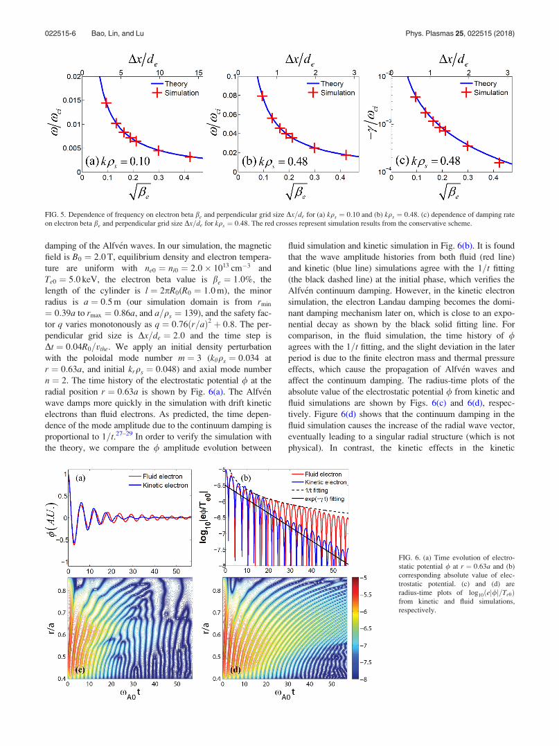
damping of the Alfv�en waves. In our simulation, the magnetic
field is B0 ¼ 2:0 T, equilibrium density and electron tempera-
ture are uniform with ne0 ¼ ni0 ¼ 2:0� 1013 cm�3 and
Te0 ¼ 5:0 keV, the electron beta value is be ¼ 1:0%, the
length of the cylinder is l ¼ 2pR0(R0 ¼ 1:0 m), the minor
radius is a ¼ 0:5 m (our simulation domain is from rmin
¼ 0:39a to rmax ¼ 0:86a, and a=qs ¼ 139), and the safety fac-
tor q varies monotonously as q ¼ 0:76ðr=aÞ2 þ 0:8. The per-
pendicular grid size is Dx=de ¼ 2:0 and the time step is
Dt ¼ 0:04R0=vthe. We apply an initial density perturbation
with the poloidal mode number m ¼ 3 (khqs ¼ 0:034 at
r ¼ 0:63a, and initial krqs ¼ 0:048) and axial mode number
n ¼ 2. The time history of the electrostatic potential / at the
radial position r ¼ 0:63a is shown by Fig. 6(a). The Alfv�en
wave damps more quickly in the simulation with drift kinetic
electrons than fluid electrons. As predicted, the time depen-
dence of the mode amplitude due to the continuum damping is
proportional to 1=t.27–29 In order to verify the simulation with
the theory, we compare the / amplitude evolution between
fluid simulation and kinetic simulation in Fig. 6(b). It is found
that the wave amplitude histories from both fluid (red line)
and kinetic (blue line) simulations agree with the 1=t fitting
(the black dashed line) at the initial phase, which verifies the
Alfv�en continuum damping. However, in the kinetic electron
simulation, the electron Landau damping becomes the domi-
nant damping mechanism later on, which is close to an expo-
nential decay as shown by the black solid fitting line. For
comparison, in the fluid simulation, the time history of /agrees with the 1=t fitting, and the slight deviation in the later
period is due to the finite electron mass and thermal pressure
effects, which cause the propagation of Alfv�en waves and
affect the continuum damping. The radius-time plots of the
absolute value of the electrostatic potential / from kinetic and
fluid simulations are shown by Figs. 6(c) and 6(d), respec-
tively. Figure 6(d) shows that the continuum damping in the
fluid simulation causes the increase of the radial wave vector,
eventually leading to a singular radial structure (which is not
physical). In contrast, the kinetic effects in the kinetic
FIG. 5. Dependence of frequency on electron beta be and perpendicular grid size Dx=de for (a) kqs ¼ 0:10 and (b) kqs ¼ 0:48. (c) dependence of damping rate
on electron beta be and perpendicular grid size Dx=de for kqs ¼ 0:48. The red crosses represent simulation results from the conservative scheme.
FIG. 6. (a) Time evolution of electro-
static potential / at r ¼ 0:63a and (b)
corresponding absolute value of elec-
trostatic potential. (c) and (d) are
radius-time plots of log10ðej/j=Te0Þfrom kinetic and fluid simulations,
respectively.
022515-6 Bao, Lin, and Lu Phys. Plasmas 25, 022515 (2018)
simulation result in the Landau damping and the formation of
normal modes with discrete frequencies (which are more phys-
ical Landau eigen states) as shown in Fig. 6(c). This indicates
that the kinetic approach for the simulations of Alfv�en waves
is not just more physical, but also numerically superior than
the fluid approach.
Furthermore, we carry out simulations of KAW using
antenna excitation to verify the propagation in cylinder plas-
mas. The radial simulation domain is from rmin ¼ 0:39a to
rmax ¼ a. The other parameters are the same as the contin-
uum damping simulation earlier in this subsection. We excite
the KAW with the poloidal mode number m ¼ 3
(khqs ¼ 0:022 at r ¼ a) and the axial mode number n ¼ 3 at
the edge by using an external antenna with local shear
Alfv�en frequency xA0 ¼ kjj0VA, where kjj0 is the parallel
wave vector at r ¼ a. The excited shear Alfv�en wave can
convert to the kinetic Alfv�en wave at the launching position
since it is also the resonant layer where the relation xA0
¼ kjjðaÞVA is satisfied; then, the KAW can propagate across
the magnetic field lines.30,31
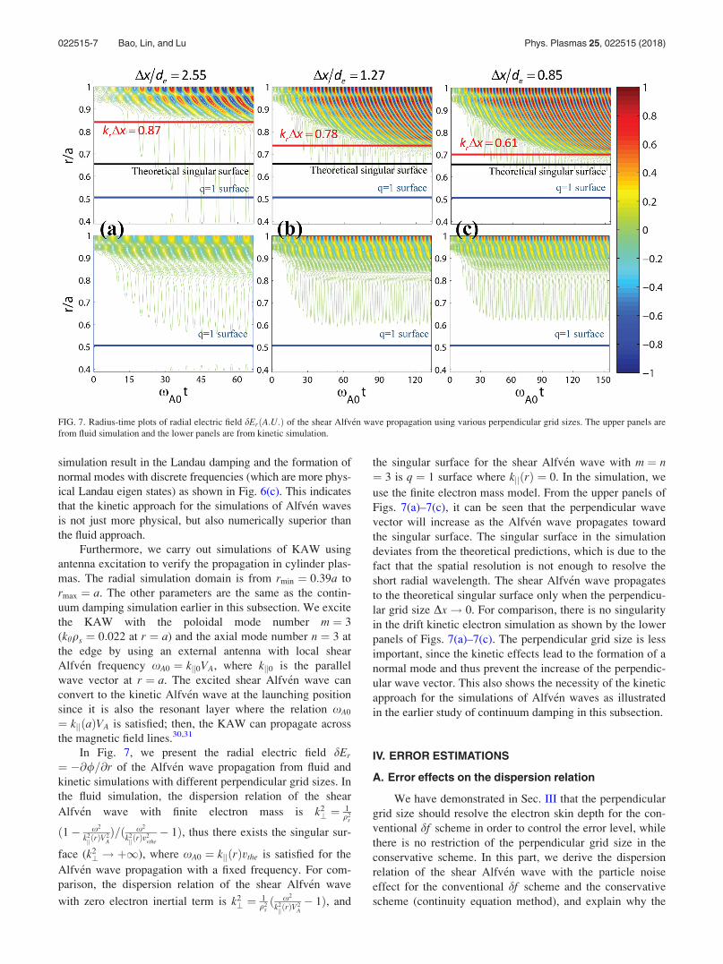
In Fig. 7, we present the radial electric field dEr
¼ �@/=@r of the Alfv�en wave propagation from fluid and
kinetic simulations with different perpendicular grid sizes. In
the fluid simulation, the dispersion relation of the shear
Alfv�en wave with finite electron mass is k2? ¼ 1
q2s
ð1� x2
k2jjðrÞV
2A
Þ=ð x2
k2jjðrÞv
2vthe
� 1Þ, thus there exists the singular sur-
face (k2? ! þ1), where xA0 ¼ kjjðrÞvthe is satisfied for the
Alfv�en wave propagation with a fixed frequency. For com-
parison, the dispersion relation of the shear Alfv�en wave
with zero electron inertial term is k2? ¼ 1
q2sð x2
k2jjðrÞV
2A
� 1Þ, and
the singular surface for the shear Alfv�en wave with m ¼ n¼ 3 is q ¼ 1 surface where kjjðrÞ ¼ 0. In the simulation, we
use the finite electron mass model. From the upper panels of
Figs. 7(a)–7(c), it can be seen that the perpendicular wave
vector will increase as the Alfv�en wave propagates toward
the singular surface. The singular surface in the simulation
deviates from the theoretical predictions, which is due to the
fact that the spatial resolution is not enough to resolve the
short radial wavelength. The shear Alfv�en wave propagates
to the theoretical singular surface only when the perpendicu-
lar grid size Dx! 0. For comparison, there is no singularity
in the drift kinetic electron simulation as shown by the lower
panels of Figs. 7(a)–7(c). The perpendicular grid size is less
important, since the kinetic effects lead to the formation of a
normal mode and thus prevent the increase of the perpendic-
ular wave vector. This also shows the necessity of the kinetic
approach for the simulations of Alfv�en waves as illustrated
in the earlier study of continuum damping in this subsection.
IV. ERROR ESTIMATIONS
A. Error effects on the dispersion relation
We have demonstrated in Sec. III that the perpendicular
grid size should resolve the electron skin depth for the con-
ventional df scheme in order to control the error level, while
there is no restriction of the perpendicular grid size in the
conservative scheme. In this part, we derive the dispersion
relation of the shear Alfv�en wave with the particle noise
effect for the conventional df scheme and the conservative
scheme (continuity equation method), and explain why the
FIG. 7. Radius-time plots of radial electric field dErðA:U:Þ of the shear Alfv�en wave propagation using various perpendicular grid sizes. The upper panels are
from fluid simulation and the lower panels are from kinetic simulation.
022515-7 Bao, Lin, and Lu Phys. Plasmas 25, 022515 (2018)
conservative scheme is superior to the conventional dfscheme theoretically.
Applying the Fourier transform: @=@t ¼ �ixt, b0 � r¼ ikjj to the linear version of Eq. (5), we can derive the per-
turbed electron distribution in the uniform plasmas
df ¼kjjvjj
x� kjjvjj/�
vjjc
dAjj
� �qe
Te0
f0; (14)
where vjj ¼ pjj=me. Electron E� B drift cancels with ion
species and does not appear.
The perturbed density and canonical flow can be derived
by integrating Eq. (14) as
dn ¼ ene0
Te0
/� 1
c
xkjj
dAjj
� �1þ neZ neð Þ½ (15)
and
Ujjc ¼ � e
cmedAjj þ
e
Te0
xkjj
/� 1
c
xkjj
dAjj
� �1þ neZ neð Þ½
� �:
(16)
In the conventional df scheme, both electron density
and canonical flow perturbations are calculated from the
kinetic markers, thus we multiply the exact solutions Eqs.
(15) and (16) by error coefficients to represent the values
measured from the simulation with particle noise. The
perturbed density and canonical flow calculated from
kinetic markers with the particle noise effect can be
expressed as32
d~n ¼ ene0
Te0
/� 1
c
xkjj
dAjj
� �1þ neZ neð Þ½ 1þ enð Þ (17)
and
~U jjc ¼ � e
cmedAjj þ
e
Te0
xkjj
/� 1
c
xkjj
dAjj
� �1þ neZ neð Þ½
� �� 1þ euð Þ; ð18Þ
where en and eu represent the particle noise errors induced
from the kinetic markers to the perturbed density and the
perturbed canonical flow, respectively, Eqs. (17) and (18)
become the exact solutions when en ¼ eu ¼ 0.
Applying the Fourier transform r ¼ ik? to Eqs. (7) and
(11) and considering Eqs. (17) and (18), we can derive the
dispersion relation of the shear Alfv�en wave with particle
noise error
x2
k2jjV
2A
� 1
!1þ neZ neð Þ½
¼ k2?q2
s
1
1þ eu� be
2
mi
me
eu
1þ eu� 1
k2?d2
e
1þ neZ neð Þ½
� eu 1þ enð Þ1þ eu
þ 1þ neZ neð Þ½ en � eu
1þ eu: (19)
Then, we can expand Eq. (19) using jenj � 1 and jeuj � 1
and only keep the first order error terms
x2
k2jjV
2A
� 1
!1þ neZ neð Þ½
¼ k2?q
2s 1� euð Þ � be
2
mi
meeu �
1
k2?d2
e
1þ neZ neð Þ½ eu
þ 1þ neZ neð Þ½ en � euð Þ: (20)
From Eq. (20), it is seen that the particle noise error is ampli-
fied with increasing be and the perpendicular wavelength
through the second and third terms on the RHS, respectively,
which explains the numerical difficulty of the electromag-
netic simulation of the long wavelength modes with k2?d2
e
� 1 in high be plasmas. For example, the numerically high
frequency modes dominate in the simulation of long wave-
length (k2?d2
e � 1) shear Alfv�en waves by using the conven-
tional df scheme as shown by Fig. 3, which are caused by
the third error term on the RHS of Eq. (20).
In the conservative scheme, we use the kinetic markers
to calculate the perturbed canonical flow as Eq. (18). The
parallel vector potential with the error effect can be calcu-
lated by using Eqs. (7) and (18)
dAjj ¼cxkjj
1þ neZ neð Þ½ 1þ euð Þ
�c2k2?k2
Dþ v2theeuþ
x2
k2jj
1þ neZ neð Þ½ 1þ euð Þ/: (21)
From Eqs. (9), (10), and (21), the perturbed density with par-
ticle noise error in the linear and uniform plasmas is
dn ¼� c2k2
?4pe
1þ neZ neð Þ½ 1þ euð Þ
�c2k2?k
2D þ v2
theeu þx2
k2jj
1þ neZ neð Þ½ 1þ euð Þ/: (22)
From Eqs. (11) and (22), the dispersion relation of the shear
Alfv�en wave with particle noise error in the conservative
scheme is
x2
k2jjV
2A
� 1
!1þ neZ neð Þ½ ¼ k2
?q2s
1
1þ eu� be
2
mi
me
eu
1þ eu:
(23)
Keeping the first order terms with respect to particle noise
error, Eq. (23) can be written as
x2
k2jjV
2A
� 1
!1þ neZ neð Þ½ ¼ k2
?q2s 1� euð Þ � be
2
mi
meeu: (24)
Compared to Eq. (20), there is no particle noise error term
related to the perpendicular wavelength in Eq. (24). It is
because that the continuity equation guarantees the consis-
tency between en and eu in the conservative scheme, and the
last two terms on the RHS of Eq. (19) cancel with each other.
Thus, the conservative scheme is more robust than the con-
ventional df scheme for the simulations of long wavelength
electromagnetic modes. For example, the conservative
scheme can simulate shear Alfv�en waves in the long
022515-8 Bao, Lin, and Lu Phys. Plasmas 25, 022515 (2018)

wavelength regimes accurately, while the conventional dfscheme fails as shown by Fig. 3. From Eqs. (20) and (24), it
is also noticed that finite be can amplify error terms for both
schemes. However, we can simulate the shear Alfv�en waves
with sufficient accuracy in the very high be regime by using
the conservative scheme as shown by Fig. 5, which indicates
that finite be effects are not as severe as long wavelength
(k2?d2
e 0) effects on the numerical properties of electro-
magnetic simulations.
B. Error effects on the parallel electric field dEjj
As we have illustrated before, the perturbed density and
canonical flow calculated from the kinetic markers do not sat-
isfy the electron continuity equation, which leads to the incon-
sistency of the corresponding electrostatic potential and vector
potential in the conventional perturbative (df ) simulation.
However, the parallel electric field dEjj 0 in the long wave-
length (ideal MHD) limit, which requires that the electrostatic
electric field dEejj ¼ �b0 � r/ and the inductive electric field
dEijj ¼ ð1=cÞ@dAjj=@t evolve consistently and their major
parts can cancel with each other in the simulation. Thus, any
inconsistency of dEejj and dEi
jj can lead to the unphysically
large dEjj, and cause the numerical instability in the conven-
tional perturbative (df ) scheme. In this part, the error effects
on the parallel electric field dEjj are discussed for both the
conventional df scheme and conservative scheme.
In the conventional df scheme, applying the Fourier
transform r ¼ ik? to Eqs. (7) and (11), and considering
Eqs. (17) and (18), the electrostatic potential and vector
potential can be represented as
/ ¼ � 4pene0V2A
c2k2?
kjjx
1þ en
1þ eu� 1þ en
1þ k2?d2
e
� �~U jjc; (25)
dAjj ¼ �d2
e
1þ k2?d2
e
4pene0
c~U jjc: (26)
Thus, the parallel electric field dEjj in the conventional dfscheme is
dEjj ¼ ime
ex
k2jjV
2A
1þ k2?d2
e
x2
k2jjV
2A
� 1
!~U jjc
þ ime
ex
k2jjV
2A
k2?d2
e
1þ en þ k2?d2
e
1þ k2?d2
e
� 1þ en
1þ eu
!~U jjc: (27)
By keeping the first order error terms based on jenj � 1 and
jeuj � 1, Eq. (27) can be simplified as
dEjj ¼ ime
ex
k2jjV
2A
1þ k2?d2
e
x2
k2jjV
2A
� 1
!~U jjc
þ ime
ex
k2jjV
2A
k2?d2
e
eu � enk2?d2
e
1þ k2?d2
e
!~U jjc: (28)
The last term on the RHS of Eq. (28) is due to inconsistency
between en and eu, which will be amplified when k2?d2
e is
small.
In the conservative scheme, the perturbed density is cal-
culated from Eq. (9) instead of Eq. (17). The electrostatic
potential can be derived by using Eqs. (9)–(11) and (26) as
/ ¼ � 4pene0V2A
c2k2?
kjjx
k2?d2
e
1þ k2?d2
e
!~U jjc: (29)
By using Eqs. (26) and (29), the parallel electric field dEjj in
the conservative scheme is
dEjj ¼ ime
ex
k2jjV
2A
1þ k2?d2
e
x2
k2jjV
2A
� 1
!~U jjc: (30)
Comparing Eqs. (28) and (30) in the long wavelength limit
with k2?d2
e � 1, it is seen that dEjj 0 with x2 k2jjV
2A for
the conservative scheme, while dEjj / 1=k2?d2
e with x2
k2jjV
2A for the conventional df scheme due to the inconsis-
tency between the perturbed density and canonical flow.
Thus, the conservative scheme can guarantee dEjj 0 in the
simulation as shown by Fig. 4(a), while the conventional dfscheme causes the unphysically large amplitude of dEjj in
the simulation as shown by Fig. 4(b), which is due to the last
error term on the RHS of Eq. (28).
V. CONCLUSIONS
In this work, we present an innovative conservative
scheme to solve the numerical difficulty of the electromag-
netic gyrokinetic particle simulation with kinetic electrons.
In the conventionally electromagnetic perturbative ðdf Þ sim-
ulation with drift kinetic electrons of pjj formulation, we
found that perturbed density and perturbed canonical flow,
calculated from the kinetic markers, do not satisfy the conti-
nuity equation due to the particle noise, which causes the
inconsistency between the electrostatic potential and parallel
vector potential and leads to an unphysically large parallel
electric field in the long wavelength MHD regime. In the
conservative scheme, we use the electron continuity equation
to time advance the electron density perturbation using the
perturbed mechanical flow calculated from the parallel vec-
tor potential, and the parallel vector potential is solved by
using the canonical flow from the kinetic markers, which
guarantees the consistency between electrostatic and parallel
vector potentials. Furthermore, the conservative scheme
helps to relax the perpendicular grid size without resolving
the electron skin depth when the wavelength is longer than
the electron skin depth. However, in the conventional elec-
tromagnetic df scheme, the perpendicular grid size needs to
resolve the electron skin depth even for the long wavelength
MHD wave simulation. The simulations of the shear Alfv�en
wave dispersion relation and continuum damping are well
benchmarked with the theory by using the conservative
scheme. In the conservative scheme, simulation of the long
wavelength shear Alfv�en wave, the electrostatic component,
and the inductive component of the electric field cancel with
each other as expected. Finally, comparison of Alfv�en wave
propagation results between gyrokinetic particle simulation
and fluid simulation shows that gyrokinetic particle simula-
tion is superior to the fluid simulation by physically avoiding
022515-9 Bao, Lin, and Lu Phys. Plasmas 25, 022515 (2018)
the singular mode structures through electron Landau damp-
ing. Building on the linear application of the conservative
scheme to shear Alfv�en wave simulation, the nonlinear simu-
lation results will be reported in the future work. Meanwhile,
the application of the conservative scheme on the drift
kinetic electron model with vjj formulation combining with
the split weight scheme has been reported in another work.33
ACKNOWLEDGMENTS
We would like to thank W. W. Lee, L. Chen, W. M.
Tang, Y. Chen, D. Liu, I. Holod, L. Shi, C. Lau, Y. Xiao,
and W. L. Zhang for the useful discussions. This work was
supported by the China National Magnetic Confinement
Fusion Science Program (Grant No. 2013GB111000), the
U.S. Department of Energy (DOE) SciDAC GSEP Program,
and the China Scholarship Council (Grant No.
201306010032). This work used resources of the Oak Ridge
Leadership Computing Facility at the Oak Ridge National
Laboratory (DOE Contract No. DE-AC05-00OR22725) and
the National Energy Research Scientific Computing Center
(DOE Contract No. DE-AC02-05CH11231).
1J. F. Drake, N. T. Gladd, C. S. Liu, and C. L. Chang, Phys. Rev. Lett. 44,
994 (1980).2Z. Wang, Z. Lin, I. Holod, W. W. Heidbrink, B. Tobias, M. V. Zeeland,
and M. E. Austin, Phys. Rev. Lett. 111, 145003 (2013).3J. V. W. Reynders, Ph.D thesis, Princeton University, 1992.4J. C. Cummings, Ph.D. thesis, Princeton University, 1995.5I. Holod and Z. Lin, Phys. Plasmas 20, 032309 (2013).6Z. Lin, paper presented at SciDAC Microturbulence Project Meeting,
General Atomics (2001).
7J. Candy and R. E. Waltz, J. Comput. Phys. 186, 545–581 (2003).8Y. Chen and S. E. Parker, J. Comput. Phys. 189, 463–475 (2003).9W. W. Lee, J. L. V. Lewandowski, T. S. Hahm, and Z. Lin, Phys. Plasmas
8, 4435 (2001).10Z. Lin and L. Chen, Phys. Plasmas 8, 1447 (2001).11R. Hatzky, A. Konies, and A. Mishchenko, J. Comput. Phys. 225, 568–590
(2007).12I. Holod, W. L. Zhang, Y. Xiao, and Z. Lin, Phys. Plasmas 16, 122307
(2009).13Y. Chen and S. E. Parker, Phys. Plasmas 18, 055703 (2011).14E. A. Startsev and W. W. Lee, Phys. Plasmas 21, 022505 (2014).15A. Mishchenko, M. Cole, R. Kleiber, and A. K€onies, Phys. Plasmas 21,
052113 (2014).16J. Bao, Z. Lin, A. Kuley, and Z. X. Wang, Phys. Plasmas 23, 062501
(2016).17J. Bao, Z. Lin, A. Kuley, and Z. X. Wang, Nucl. Fusion 56, 066007 (2016).18T. S. Hahm, W. W. Lee, and A. Brizard, Phys. Fluids 31, 1940 (1988).19A. J. Brizard and T. S. Hahm, Rev. Mod. Phys. 79(2), 421 (2007).20A. M. Dimits and W. W. Lee, J. Comput. Phys. 107, 309 (1993).21S. E. Parker and W. W. Lee, Phys. Fluids B 5, 77 (1993).22W. Deng, Z. Lin, and I. Holod, Nucl. Fusion 52, 023005 (2012).23W. W. Lee, J. Comput. Phys. 72, 243 (1987).24Z. Lin, T. S. Hahm, W. W. Lee, W. M. Tang, and R. B. White, Science
281, 1835 (1998).25D. Liu and L. Chen, Phys. Scr. 84, 025506 (2011).26D. Liu, J. Bao, T. Han, J. Wang, and Z. Lin, Phys. Plasmas 23, 022502
(2016).27H. Grad, Phys. Today 22(12), 34 (1969).28J. Tataronis and W. Grossmann, Z. Phys. 261, 203 (1973).29W. Grossmann and J. Tataronis, Z. Phys. 261, 217 (1973).30A. Hasegawa and C. Uberoi, The Alfv�en Wave (U.S. Department of
Energy Technical Information Center, Oak Ridge, DOE/TIC-11191,
1982), Vol. 46, p. 54.31A. Hasegawa and L. Chen, Phys. Fluids 19, 1924 (1976).32E. Startsev, W. W. Lee, and W. Wang, Bull. Am. Phys. Soc. 60, JP12.129
(2015).33J. Bao, Z. Lin, and Z. X. Lu, Phys. Plasmas 24, 102516 (2017).
022515-10 Bao, Lin, and Lu Phys. Plasmas 25, 022515 (2018)
Top Related