


Languages
Pages
Legal

Journal of Civil Engineering and Architecture 9 (2015) 780-790 doi: 10.17265/1934-7359/2015.07.004
A Comparative Study on Linear Effective Properties
Predictions of an Argillite Rock Using XFEM
Senjun Wu, Naima Belayachi, Dashnor Hoxha and Duc-Phi Do
University of Orléans, INSA-CVL, PRISME, EA 4229, Orléans 45072, France
Abstract: The mechanical behavior of geomaterials is studied using an XFEM (extended finite element method). Usually, the modeling of such heterogeneous material is performed either through an analytical homogenization approach, or numerically, especially for complex microstructures. For comparison, the effective properties are obtained using a classical finite element analysis (through the so-called unit cell method) and an analytical homogenization approach. The use of XFEM proposed here retains the accuracy of the classical finite element approach, allowing one to use meshes that do not necessarily match the physical boundaries of the material constituents. Thanks to such methods, it is then possible to study materials with complex microstructures that have non-simplified assumptions commonly used by other methods, as well as quantify the impact of such simplification. The versatility of XFEM in dealing with complex microstructures, including polycrystalline-like microstructures, is also shown through the role of shape inclusions on the overall effective properties of an argillite rock. Voronoi representation is used to describe the complex microstructure of argillite. Key words: XFEM, micromechanics, argillite, homogenization, Voronoi microstructure, linear behavior.
1. Introduction
Heterogeneous geomaterials, like rocks and soils,
play a large role in engineering applications. Modeling
their behavior accurately is still a challenge. Their
macroscopic behavior is complex and strongly
influenced by their geological history, their natural
composition, and also by complex microstructures
resulting in a difference between macroscopic and
microscopic scales. Consequently, modeling their
behavior accurately is still a challenge.
Basically, nowadays, two alternative and
complementary approaches are commonly followed to
describe the mechanical behavior of such materials.
First, macroscopic models are the models most used in
practice and suppose that the material’s behavior at any
material point is identical to that of a REV
(representative elementary volume). In addition, the
macroscopic models describe the material behavior
Corresponding author: Naima Belayachi, Ph.D., research
fields: non-linear mechanical behavior, micro-macro modeling, coupling modeling and thermo-hydro-mechanical material characterization. E-mail: [email protected].
following a well-established thermodynamic
framework [1, 2]. Alternatively, micromechanical
models try to establish the constitutive relations in the
REV by considering the structure of material and
behavior for each of its constituents, a task known as
upscaling. In particular, among various analytical
micromechanical approaches, the Eshelby
inhomogeneous inclusion solution [3] can be used to
distinguish between them, including variational
approaches allowing for the estimation of the bounds of
various parameters [4-6]. In addition, the Mori-Tanaka
scheme [7] is another well-known micromechanical
approach. Despite the important achievements
obtained using such analytical methods in the design of
new materials and in the predictions of various
effective properties of natural heterogeneous materials,
they are limited when it comes to some particular
shapes of constituents (most often elliptical or
cylindrical) [7].
Thanks to the development of computational
techniques, the numerical homogenization method has
made considerable progress in taking into account the
D DAVID PUBLISHING
A Comparative Study on Linear Effective Properties Predictions of an Argillite Rock Using XFEM
781
sophisticated behaviors of constituents and complex
microstructures of heterogeneous engineering
materials. In the majority of published studies, these
numerical methods are based on the FEM (finite
element method) and make use of the representative
unit cell concept as a generalization of periodic
materials [8, 9].
To simulate a periodic material, some specific
boundary conditions, known as periodic boundary
conditions, must be applied on the unit cell. These
conditions could either be of the constraint
displacement type [8, 9] or of the free boundary type,
and are supposed to reproduce (at least approximately)
the conditions of the boundaries of the neighbor cells of
a periodic material.
As first proposed by Belytschko and Black [10] and
Moës et al. [11], the XFEM (extended finite element
method) is established as a serious alternative to the
classical FEM for problems of crack propagation
without remeshing. Further on, the method was applied
to model heterogeneous material, such as a matrix
containing inclusions or holes [12]. The description of
material discontinuities in the context of XFEM is
often realized by the so-called LSM (level-set method)
[13]. This numerical technique, initially used for
tracking moving interfaces, is able to describe the
boundaries of constituents of heterogeneous materials
in a simple way, represented by the zero level set
curves [12].
In this paper, a homogenization procedure of
heterogeneous geomaterials, based on the XFEM
approach, similar to that of Moës et al. [11], is used to
model the behavior of the argillite of M/HM argillite
(Meuse Haute Marne), extensively studied in the
Underground Research Laboratory of Bure (France) in
the framework of geological barrier nuclear waste
disposals studies [1, 2].
In particular, the effective properties of the argillite
rock will be predicted here by considering two
microstructure representations: a simplified two-phase
matrix-inclusion structure, focusing the analysis on the
impact of inclusion and a grain-to-grain microstructure
with four phases. This rock, at the mesoscopic level
(some millimeters to some centimeters), appears as a
composite material with dominating clay-like grains
and random mineral (quartz and calcite) grains
occupying up to 40% of the rock’s volume, with 2% of
macropores [14].
In contrast to classical FEM numerical analysis with
a very limited number of inclusions, in this section, we
use a great number of inclusions for some standard
spatial distributions with various shapes for which
analytical estimators exist [7] in order to verify the
well-founded unit cell approach. In addition, the
inclusions are used, to some extent, to quantify the
errors that could be raised from some practices of
numerical and analytical homogenization. We then
focused on the evaluation of effective properties and
local stress-strain fields of a clay-like rock, using a
combination of the XFEM method and a Voronoi
tessellation [15-17], which allows for a numerical
description of rock microstructure close to that
observed in the laboratory [14]. The combination of the
capability of XFEM method to modeling complex
microstructure and homogenization approach is used in
the aim to obtain realistic representation of argillite
microstructure, as well as, to study the internal stresses
and strains field with more accuracy. The objective is
also to study the effect of the inclusions morphology on
the effective properties.
In this paper, a bared capital letter (eg., X) refers to a
four-order tensor and a bold face symbol (eg., X) refers
to second-order tensor. A bold face underlined symbol
(eg., x ) represents a vector, while an italic symbol (eg.,
x) represents a scalar.
2. Modeling Procedure
A detailed description of the XFEM is beyond the
scope of this paper. However, the interested reader
would find a quite complete description of the method
in the work of Moës et al. [11], as well as in the
references wherein. Nevertheless, for the sake of
A Comparative Study on Linear Effective Properties Predictions of an Argillite Rock Using XFEM
782
clarity, we briefly present the principle of the XFEM,
in addition to the calculation procedures used in this
work. The numerical code developed for this purpose,
in 2D and 3D, is a sequence of MATLAB-based
routines, following the initial work of Chessa et al.
[18].
2.1 XFEM in Context of an Up-scaling Procedure
The whole strategy of numerical up-scaling consists
of three distinct steps: choosing and meshing an REV
(representative elementary volume) of material,
describing in some way its structure, solving a
simplified problem on this REV, applying suitable
loadings and boundary conditions, and calculating
averaged values for stress and strains, and deducing
values for stiffness coefficients. The principal
difference of the XFEM-based homogenization
method with a classical approach resides in the first
step of the homogenization and concerns both
describing the microstructure and constructing an
approximated solution.
Generally speaking, the XFEM is a numerical
technique that extends the classical FEM
approximation by enrichment functions that count for
the existence of discontinuities in the structure.
Compared to the classical FEM, where the mesh must
conform to the surfaces of discontinuity, XFEM uses a
uniform mesh to integrate partial differential equations
[11]. This mesh is independent of the geometry of the
microstructure that facilitates the use of the method in
the case of complex geometries and microstructures.
In XFEM, the surfaces of discontinuities (inclusions,
cracks and pores…) are taken into account by enriching
the finite element approximation with some kind of
functions, so that the displacement approximation
could be written in the following general form [10, 11]: ENRFEMXFEM uuu
)()()( xxaux FNNJ
JJIi
ii
(1)
where, I is the set of nodes in the mesh, iu is the
classical unknown nodal value at the i-th node and
)(xiN is the classical shape function of FEM
approximation; J represents the set of all nodes
concerned with enriching approximation, while Ja is
the set of new degrees of freedom and )(xF is the
enrichment function. Only the nodes of elements
containing a portion of the interface are enriched in
order to take into account the discontinuity of
displacements through this interface.
When XFEM is used for homogenization purposes,
the level set functions are used to describe a boundary
between two components and amount to a value
associated with that boundary [12]. In particular, they
allow for calculating, at each node of the mesh, a value
representing the signed distance between the node
and the boundary (a negative value within a void or
inclusion and a positive value outside).
In the simplest case of a set of n spherical inclusions,
for example, the value of this function in a point x is
written [12, 19]:
( ) min{ }
1, 2, ...
i ic c
i ic c
r
i n
x x x
x
(2)
where, icx and
icr are the centre and radius of the i-th
inclusion, respectively. It is then possible to calculate an interpolated value
of this function at any other point x:
J
JJN )()( xx (3)
with NJ being the shape function associated with Node
J of the elements that are cut by interface, and J is
the nodal value of the level set function [12].
2.2 Enrichment Function and Integration of Enriched
Elements
The enrichment function depends on the nature of
the problem studied. For example, with a crack analysis
problem, the enriched terms (ENRu ) are chosen in
such a way that both jump displacement through the
crack and singularity of stress on the crack’s tip are
considered [10]. More recently, authors used XFEM
enrichment displacement to model complex behavior
by combining non-linear bridged crack models [20] or

A Comparative Study on Linear Effective Properties Predictions of an Argillite Rock Using XFEM
783
plasticity dynamic dislocation [21] and advantages of
classical XFEM to describe arbitrary cracks.
In the homogenization problem we are dealing with
here, the enrichment function for describing the
inclusion interface is often constructed using the level
set functions. Two enrichment functions for the
interface of inclusions have been proposed in previous
works [22, 23], for a simple case of a 2D circular
inclusion in a reference four nodes quadrilateral
element:
J
JJ NF )()(1 xx (4)
J
JJJ
JJ NNF )()()(2 xxx (5)
where, the function F1(x) has a 0 value on the interface
of inclusions and it reaches its maximum at the
boundary of the element, whereas the function F2(x)
has 0 values at the boundary of the element and in all
elements that are not traversed by the interface [23],
avoiding the blending errors due to the partially
enriched element [18]. In what follows, the function
F2(x) (Eq. (5)) is used as the enriched function.
Special attention should be paid to the enriched
element crossed by the interface where the integration
is performed. In fact, on such elements, in as much as
Lagrange elements are used for FEM formulation, the
gradients of displacement are discontinuous, and
therefore, Gauss-Lagrange integration on the whole
element is not any more suitable.
In this paper, a separate integration on each side of
the interface of an enriched element is performed, as
suggested in previous research [22]. For that process,
during the integration, the enriched element is divided
into sub-elements, each of them fully found in one of
the domains separated by the interface. Then, for each
convex sub-element, the integration is performed in a
classical way, using either four (in 3D case) or three (in
2D case) integration points [22].
3. Results and Discussions
In the following sections, we apply this
homogenization procedure to study the influence of
some microstructure features on the effective elastic
properties of a geomaterial. The results obtained by
XFEM are compared with classical FEM unit
cell-based simulations and/or analytical estimations.
For analytical evaluations, we use a Mori-Tanaka
scheme [7], while the FEM simulations are performed
with ABAQUS.
For simplicity purposes, the problem of influencing
the effect of inclusions on effective properties is
studied here through the use of 2D configurations,
using a regular mesh of 433 × 433 nodes. The analysis
will focus on four stiffness coefficients (X1111, X2222,
X1122 and X2211), obtained by two independent loading
tests (respectively in horizontal and vertical directions
indicated by indices 1 and 2). More test loadings are
necessary to identify all coefficients of stiffness tensor.
3.1 Effective Properties of Matrix Inclusion
Geomaterials with Different Inclusion’s Shapes
In most published results on the role of inclusion’s
shape on effective properties, particularly for analytical
approaches, it is supposed that heterogeneities have
sufficient “regular” shapes (more often ellipsoidal or
cylindrical). It is supposed that this simplification
offers a sufficient accuracy for most practical purposes,
even if the question of the effect of this simplification
on effective properties is not yet clear.
The impact of inclusion’s shape is thought to be even
more important in plasticity, where, up until now,
numerical methods based on unit cells are considered
to be a benchmark to evaluate approximated analytical
methods. In the case of unit cells, one chooses a pattern
of microstructure that is as close as possible to the
reality by using a (very limited) number of inclusions
and performing numerical analyses.
There are some published results from some authors
where XFEM is already used in the context of the unit
cell method [19]. However, using XFEM makes it
possible to study this problem with a wide range of
inclusion numbers, making it possible to verify the

A Comparative Study on Linear Effective Properties Predictions of an Argillite Rock Using XFEM
784
well-founded beliefs regarding the unit cell method. In
addition, it also makes it possible to eventually
quantify, to some extent, the errors introduced by its
practice in linear problems. This question is
investigated here by XFEM in a number of 2D plan
deformation problems using four different inclusion
shapes: circular, elliptical, triangular and non-convex
star-like inclusions (Fig. 1).
In order to allow for a comparison of XFEM results
and numerical unit cell methods, first, a simplified
structure of argillite is considered to be limited in only
two phases: the porous clay matrix and mineral
inclusions (quartz and calcite are considered identical),
represented by calcite inclusions that with properties
that are known from published data (Table 1) [9].
For each shape, a set of random realizations of
inclusions has been performed, with each realization
containing 100 inclusions. For all cases, the same volume
fraction of inclusions is considered (f = 20%). All
circular shape inclusions have the same radius of 25 μm.
For polygonal and elliptical shapes, the level set
function was constructed with the following equation
(Eq. 2), which, in this case, is given by:
( ) min{ }
1, 2,...
ic
i ic c
L
i n
x x x
x (6)
where, L is the distance between the centre icx
and
Ix ( Ix is defined as the intersection between
}{ xx ic and the boundary of inclusion), i.e.:
Fig. 1 Shape inclusions used in numerical simulations.
Table 1 Elastic properties of the constituents for two-phase microstructure model.
Elastic properties Porous clay matrix Inclusion
Young’s modulus 7,600 MPa 84,000 MPa
Poisson’s ratio 0.1 0.3
1
2
A Comparative Study on Linear Effective Properties Predictions of an Argillite Rock Using XFEM
785
IicL xx (7)
For the elliptical shape inclusion, the semi-axes are
a1 = 1/3 × a2, a2 = 44 μm (so that the factor shape is
1/3), respectively. Finally, the triangular-shape
inclusions have a side length equal to 68 μm. For the
shapes where the orientation has a sense, a constant
orientation is kept during all realizations, so that the
randomness concerns only the centers of inclusions.
For the non-convex shapes, the radius icr in Eq. (2)
is replaced by the following function (cylindrical
coordinates):
)cos()( 0 barrc
(8)
where, r0 is the reference radius, a is the amplitude of
oscillation, b indicates the number of oscillations (the
following parameters are taken in this work: r0 = 24 μm,
a = 0.4r0, b = 4).
The mean values of the properties in the plane (X1111,
X2222, X1122 and X2211), obtained from averaging the
four realizations of random populations of each shape
inclusion, are represented in Table 2.
For these conditions, the differences on effective
properties, predicted by the FEM unit cell method and
the XFEM predicted values, are small and, in the worst
case (for non-convex star-like inclusions), the
differences are smaller than 8%. These results seem to
justify, to some extent, at least as a first approximation,
the use of the unit-cell method in predictions of random
materials for which the periodicity is not always
verified. Also, it is noted that, in as much as the
inclusion’s fraction volume is the same, the shape of
inclusions, for the cases studied here, has only a
moderated impact on the effective mechanical
properties. Indeed, even if one considers the X1111
evolution, one could observe that, regardless of the fact
that the difference becomes higher with the inclusion
shape deviating from the circle, to the non-convex
star-like inclusion (with the highest values for this last
one shape in Table 2), the differences between circular
and non-convex shape inclusions are less than 8%. A
significant difference was noted between the XFEM
and analytical methods, reaching 15% for elliptical
inclusion because of the elliptical distribution of the
Mori-Tanaka scheme.
3.2 Effective Properties of M/HM Argillite with Grain
Voronoï Microstructure
While the matrix-inclusion microstructure model
used in the previous section describes quite well the
behavior of a great number of geomaterials, in many
other cases, a grain-to-grain or a so-called
polycrystalline structure is more appropriate to describe
Table 2 Effective stiffness coefficients for different shapes of inclusions (matrix-inclusion structure).
Shape of inclusion Different methods X1111 (MPa) X2222 (MPa) X1122 (MPa) X2211 (MPa)
Circular inclusion
XFEM 10,596 10,546 1,597 1,597 FEM (ABAQUS) 10,362 10,362 1,535 1,535 Relative difference (%) 2.2 1.7 3.9 3.8 Mori-Tanaka 11,192 11,192 1,698 1,698 Relative difference (%) 5.6 6.1 6.3 6.3
Elliptical inclusion
XFEM 9,958 12,129 1,587 1,593
FEM (ABAQUS) 9,728 11,658 1,535 1,566 Relative differences (%) 2.3 3.8 3.2 1.6 Mori-Tanaka 9,651 13,954 1,620 1,620 Relative difference (%) 3.1 15 2.1 1.7
Triangular inclusion XFEM 10,999 10,940 1,685 1,684 FEM (ABAQUS) 10,908 10,700 1,599 1,582 Relative difference (%) 0.8 2.2 5.1 6.0
Non-convex inclusion XFEM 11,068 11,077 1,717 1,715 FEM (ABAQUS) 10,701 10,701 1,589 1,589 Relative difference (%) 3.3 3.4 7.5 7.4
A Comparative Study on Linear Effective Properties Predictions of an Argillite Rock Using XFEM
786
their microstructure. In this section, this grain-to-grain
microstructure is obtained using Voronoï tessellations,
as is often the case in published works [16, 17].
In order to make a comparison with the results of the
matrix inclusion structural model used in the previous
section, two-phase Voronoï clay particles and calcite
grains are considered using a total of 1,000 grains and a
volume fraction of calcite equals to 20%. For each
realization, sites were randomly generated, then used
as a basis for the Voronoï tessellation. The results
obtained using a Voronoï aggregate differ from those
obtained using triangular inclusions, with differences
that are smaller than 5% (Table 3). These differences
grow to 10% when comparisons are made between
circular inclusions and Voronoï aggregates.
At the level where this study is performed, the rock
could be considered a four-phase composite composed
by clay particles (enclosing up to 18% of voids in an
inferior scale), quartz and calcite grains and (macro)
pores (Table 4). At this level, the volume fractions of
these four phases satisfy the unity partition, (i.e., fm +
fqu + fca + fvo = 1), where, the subscripts m, qu and ca
stand for clay-like, quartz and calcite grains
respectively, and vo stands for macro voids.
While there are some interesting works on
poromechanical properties of this rock, all of them are
obtained by supposing a simplified structure of the
matrix-inclusion type [24]. As previously discussed,
this simplification would lead to unjustifiable
differences to the reality and a more realistic structure
should be considered.
The combination versatility of the Voronoi scheme
with the XFEM method seems to be a very good way to
obtain stiffness tensor using quite realistic (and
representative) polycrystalline-like structures for
M/HM argillite, as well as to study, in detail, the
internal strains and fields due to a dominant
compressive stress. In fact, even if this paper is
limited to linear mechanical behavior, it is of great
interest to examine internal stress and strain fields in
order to shed light on the eventual role of rock
heterogeneity on the nucleation of sites with high stress
and/or strain concentration that could be the origin of
the crack initiation and rock damage observed in
laboratory.
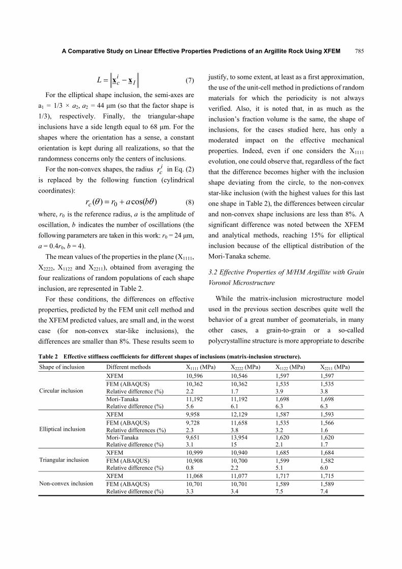
The volume fractions of constitutive phases of
M/HM argillite and their mechanical properties are
given in Table 4. The behavior of each grain is
considered to be a linear elastic one. A compressive
mechanical loading of 10 N is applied on the upper side
of the REV (Fig. 2), showing an example of
polycrystalline-like microstructure realization, with
free lateral faces and vertical constrained displacement
on the lower face.
As observed in Table 5, an almost isotropic material
is obtained using Voronoi tessellations and random
Table 3 Comparison of effective stiffness coefficients of two-phase Voronoï material with various cases of two-phase matrix-inclusion structures.
Shape of inclusion and differences X1111 (MPa) X2222 (MPa) X1122 (MPa) X2211 (MPa)
(1) Circular inclusions 10,596 10,546 1,597 1,597
(2) Triangular inclusions 10,999 10,940 1,685 1,684
(3) Two-phase Voronoï 11,121 11,162 1,767 1,766
Differences between (1) and (3) (%) 5.1 5.8 10.7 10.6
Differences between (2) and (3) (%) 1.1 2.0 4.9 4.9
Table 4 Elastic properties of the constituents for four-phase microstructure model.
Elastic properties Calcite Quartz Porous clay matrix Macropores
Young’s modulus (MPa) 84,000 96,400 7,600 0
Poisson’s ratio 0.3 0.08 0.1 0
Volume fraction 0.19 0.15 0.64 0.02
A Comparative Study on Linear Effective Properties Predictions of an Argillite Rock Using XFEM
787
(a) (b)
Fig. 2 A realization of 2D polycrystalline-like microstructure: (a) 2D two-phase Voronoï material (grey sites represent calcite inclusion; blue argillaceous matrix); (b) 2D microstructure of M/HM argillite as a four-phase Voronoï material (blue—clay particles; pink—quartz grains; cyan—calcite grains; white—macropores).
Table 5 Comparison of the effective stiffness coefficients of polycrystalline M/HM argillite.
Effective properties (MPa) XFEM (four-phase Voronoï) Mori-Tanaka Relative differences (%)
X1111 14,084 12,304 12
X2222 13,616 12,304 11
X1122 2,632 2,284 11
X2211 2,616 2,284 11
distributions of grain centers. In this table, the results
obtained using polycrystalline-like microstructures of
M/HM argillite and the XFEM method are presented.
In addition, the Mori-Tanaka scheme and a commonly
used microstructure of this rock containing an
argillaceous matrix and voids and mineral inclusions
(calcite and quartz) of cylindrical inclusions are shown.
Beyond the differences due to the not-quite-isotropic
behavior of the polycrystalline aggregate, these results
show a systematic underestimation of around 11% of
elastic properties from the analytical approach, as
compared to direct polycrystalline numerical
estimation. This result is important for the assessment
of the properties of this rock in situ. In fact, in practice,
the properties of clay particles constituting the
argillaceous matrix are identified through inverse
analytical or semi-analytical analyses, knowing the
properties of calcite and quartz, the volume fraction of
each phase and the effective properties obtained by
classical tests on representative volumes [24]. In light
of results obtained using polycrystalline-like structures,
it seems that this inverse analytical estimation of the
elastic properties of the clay particles would lead to an
overestimation of these properties of greater than
10%.
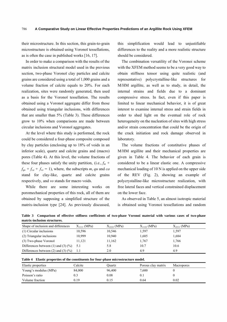
Maps of stress and strain fields in the argillite due to
vertical compressive stress are given in Figs. 3 and 4.
For the loading conditions and microstructure
presented here, the macroscopic stress and strains are
10 MPa and -0.3%, respectively.
As shown in Figs. 3 and 4, the distribution of stresses
and strains is very inhomogeneous and reveals an effect
of spatial distribution of the constituents, as well as
contacts of grains with the contrasted elastic properties:
a high strain gradient is observed around quartz and
calcite grains in Fig. 3a. Consequently, these sites of
high deformation gradients are the preferential zones of
stress concentrations and tensile stress occurrences, as
(b)(a)
A Comparative Study on Linear Effective Properties Predictions of an Argillite Rock Using XFEM
788
(a) (b)
Fig. 3 Strain fields maps in a 2D polycrystalline microstructure of M/HM due to compressive loading in vertical direction: (a) strain fields in 22 direction ; (b) strain fields in 11 direction.
(a) (b)
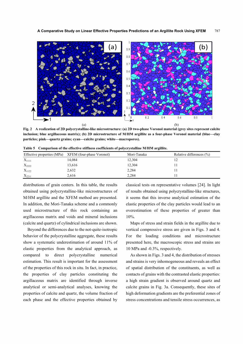
Fig. 4 Stress field distribution in a 2D polycrystalline microstructure of M/HM due to compressive loading in vertical direction: (a) stress fields in 22 direction ; (b) stress fields in 11 direction.
shown in Fig. 4. It is more noteworthy that these tensile
stresses appear at the boundaries of the argillaceous
grains with those of quartz/calcite (Figs. 4a and 4b).
While this analysis is quite qualitative, it
nevertheless shows that the spatial grain distribution
has a significant impact on the local deformation fields
and could be the origin of the non-linear
elasto-plasto-damage behavior of this rock. A
quantitative prediction of damage initiation and
evolution under compressive loading needs an
understanding of the nonlinear behavior of clay
particles and contacts, and constitutes an issue for
on-going studies.
4. Conclusions
In this paper, we have proposed a numerical
homogenization procedure by using the XFEM in the
context of the linear mechanical behavior of
geomaterials. In addition, the use of level set function
ensures to handle efficiently complex geometries with
a regular mesh, whereas the use of the finite element
method would have induced a new construction of the
mesh to each distribution of particles. The various
applications have validated the development with the
(a) (b)
1
2
(b)(a)
1
2
ε22 (MPa) ε11 (MPa)
ε22 (MPa) ε11 (MPa)

A Comparative Study on Linear Effective Properties Predictions of an Argillite Rock Using XFEM
789
XFEM in MATLAB and demonstrated the capability
of this method to predict the effective properties of
heterogeneous materials such as geomaterials. The
XFEM provides similar results to those obtained with
classical finite element method and analytical method
in many cases, justifying in many situations the use of
analytical and periodic unit-cell approaches. However,
as it is expected, XFEM simulations demonstrate that
neglecting or simplifying the shape of constituents or
their spatial distribution, even when a periodic unit cell
is used, would lead to differences that could not be any
more negligible. In the case of the M/HM argillite
studied in detail, the differences between XFEM
estimations using a polycrystalline-like structure and
the Mori-Tanaka, considering the spherical mineral
inclusions in an argillaceous matrix, grows 10% with
the Mori-Tanaka systematic underestimation. One
could speculate that such differences would be
amplified in the case of nonlinear behavior subject of
ongoing studies.
By taking into account the structure complexity of a
whole REV, the XFEM seems to represent a very
serious method for design of composite materials and
analyzing of heterogeneous materials in general.
References
[1] Hoxha, D., Giraud, A., Homand, F., and Auvray, C. 2007. “Saturated and Unsaturated Behaviour Modelling of Meuse-Haute/Marne Argillite.” International Journal of Plasticity 23: 733-66.
[2] Chiarelli, S., Shao, J. F., and Hoteit, N. 2003. “Modeling of Elastoplastic Damage Behavior of a Claystone.” International Journal of Plasticity 19: 23-45.
[3] Eshelby, J. D. 1957. “The Determination of the Elastic Field of an Ellipsoidal Inclusion, and Related Problems.” In Proceedings of the Royal Society of London, 376-96.
[4] Hashin, Z., and Shtrikman, S. 1963. “A Variational Approach to the Theory of the Elastic Behaviour of Multiphase Materials.” Journal of the Mechanics and Physics of Solids 11: 127-40.
[5] Castañeda, P. P. 1991. “The Effective Mechanical Properties of Nonlinear Isotropic Composites.” Journal of the Mechanics and Physics of Solids 39: 45-71.
[6] Willis, J. R. 1977. “Bounds and Self-consistent Estimates for the Overall Properties of Anisotropic Composites.” Journal of the Mechanics and Physics of Solids 25:
185-202. [7] Mori, T., and Tanaka, K. 1973. “Average Stress in Matrix
and Average Elastic Energy of Materials with Misfitting
Inclusions.” Acta Metallurgica 21: 571-4.
[8] Doghri, I., and Ouaar, A. 2003. “Homogenization of
Two-Phase Elasto-Plastic Composite Materials and
Structures: Study of Tangent Operators, Cyclic Plasticity
and Numerical Algorithms.” International Journal of
Solids and structures 40: 1681-712.
[9] Belayachi, N., Do, D. P., and Hoxha, D. 2012. “A Note on the Numerical Homogenization of the Mechanical Behavior of an Argillaceous Rock.” Computers and Geotechnics 41: 70-8.
[10] Belyschko, T., and Black, T. 1999. “Elastic Crack Growth
in Finite Elements with Minimal Remeshing.”
International Journal for Numerical Methods in
Engineering 45: 601-20.
[11] Moës, N., Dolbow, J., and Belytshko, T. 1999. “A Finite Element Method for Crack Growth without Remeshing.” International Journal for Numerical Methods in Engineering 46: 131-50.
[12] Sukumar, N., Chopp, D. L., Moës, N., and Belytschko, T.
2001. “Modeling Holes and Inclusions by Levelsets
in the Extended Finite-Element Method.” Computer
Methods in Applied Mechanics and Engineering 190:
6183-200.
[13] Sethian, A. 2000. Level Set Methods and Fast Marching
Methods: Evolving Interfaces in Computational Geometry,
Fluid Mechanics, Computer Vision, and Materials Science.
New York: Cambridge University Press.
[14] Yven, B., Sammartino, S., Geraud, Y., Homand, H., and
Villieras, F. 2007. “Mineralogy, Texture and Porosity of
Callovo-Oxfordian Argillites of the Meuse/Haute-Marne
Region (Eastern Paris Basin).” Mémoires de la Société
Géologique de France 178: 73-90.
[15] Ghosh, S., and Moorthy, S. 1995. “Elastic-Plastic
Analysis of Arbitrary Heterogeneous Materials with the
Voronoï Cell Finite Element Method.” Computer
Methods in Applied Mechanics and Engineering 121:
373-409.
[16] Forest, S., Barbe, F., and Gailletaud, G. 2000. “Cosserat
Modelling of Size Effects in the Mechanical Behaviour of
Polycrystals and Multi-phase Materials.” International
Journal of Solids and Structures 37: 7105-26.
[17] Aurenhammer, F. 1991. “Voronoï Diagrams Survey of a
Fundamental Geometric Data Structure.” ACM
(Association for Computing Machinery) Computing
Surveys 23: 345-405.
[18] Chessa, H. W., and Belytschko, T. 2003. “On the Construction of Blending Elements for Local Partition of Unity Enriched Finite Elements.” International Journal for Numerical Methods in Engineering 57: 1015-38.

A Comparative Study on Linear Effective Properties Predictions of an Argillite Rock Using XFEM
790
[19] Yvonnet, J., Quang, H. L., and He, Q. C. 2008. “An XFEM/Level Set Approach to Modeling Surface/Interface Effects and to Computing the Size-Dependent Effective Properties of Nanocomposites.” Computational Mechanics 42: 119-31.
[20] Afshar, A., Daneshyar, A., and Mohammadi, S. 2015. “XFEM Analysis of Fiber Bridging in Mixed-Mode Crack Propagation in Composites.” Composite Structures 125: 314-27.
[21] Keyhan, M., Goudarzi, M., Mohammadi, S., Roumina, R. 2015. “XFEM-Dislocation Dynamics Multi-scale Modeling of Plasticity and Fracture.” Computational Materials Science 104: 98-107.
[22] Dréau, K., Chevaugeon, N., and Moës, N. 2010. “Studied XFEM Enrichment to Handle Material Interfaces with Higher Order Finite Element.” Computer Methods in Applied Mechanics and Engineering 199: 1922-36.
[23] Moës, N., Cloirec, M., and Cartraud, P. 2003. “A Computational Approach to Handle Complex Microstructure Geometries.” Computer Methods in Applied Mechanics and Engineering 192: 3163-77.
[24] Giraud A, Huynh, Q. V., Hoxha, D., and Kondo, D. 2007. “Application of Results on Eshelby Tensor to the Determination of Effective Poroelastic Properties of Anisotropic Rocks-Like Composites.” International Journal of Solids and Structures 44: 3756-72.
Top Related