


Languages
Pages
Legal

8025
Page 1/16www.burkert–usa.com
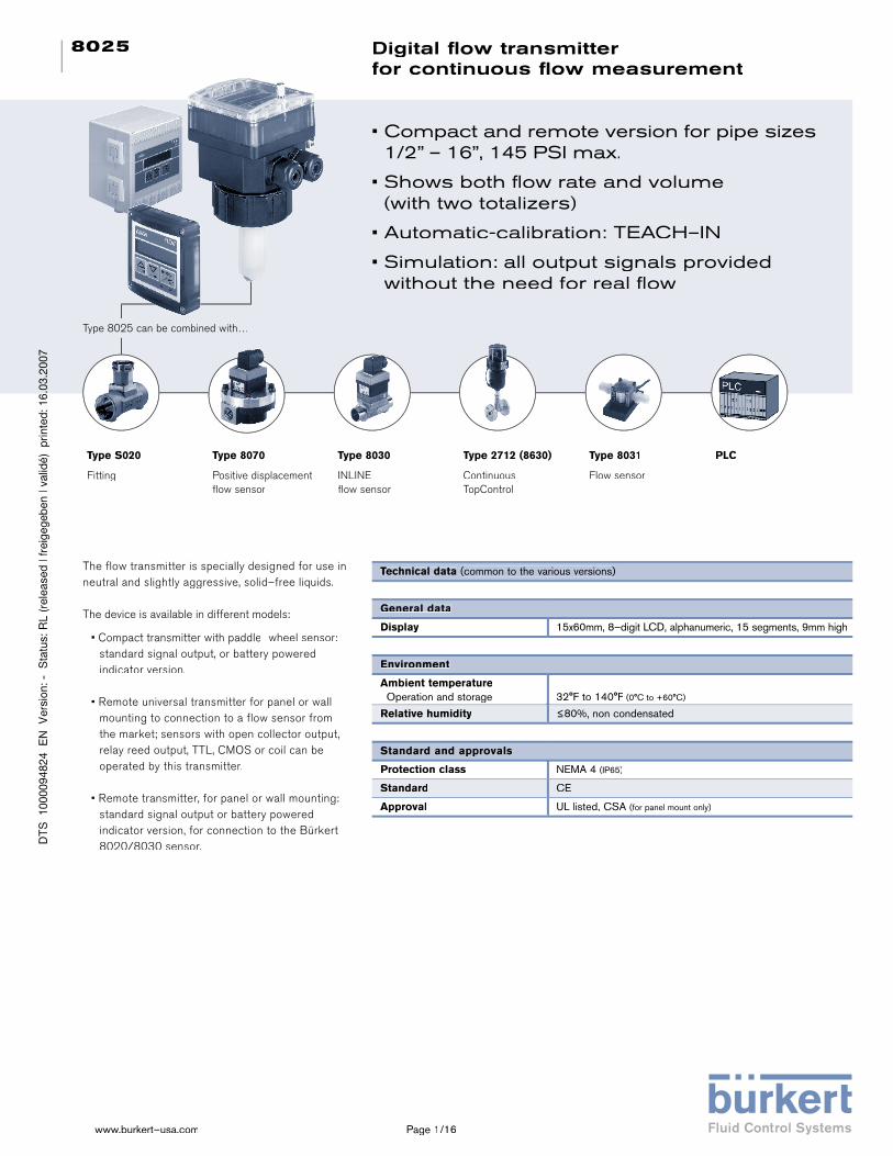
Digital fl ow transmitter for continuous fl ow measurement
• Compact and remote version for pipe sizes 1/2” – 16”, 145 PSI max.
• Shows both fl ow rate and volume (with two totalizers)
• Automatic-calibration: TEACH–IN
• Simulation: all output signals provided without the need for real fl ow
Type S020
Fitting
Type 8070
Positive displacement fl ow sensor
Type 8030
INLINE fl ow sensor
Type 2712 (8630)
Continuous TopControl
The flow transmitter is specially designed for use in neutral and slightly aggressive, solid–free liquids.
The device is available in different models:
• Compact transmitter with paddle–wheel sensor: standard signal output, or battery powered indicator version.
• Remote universal transmitter for panel or wall mounting to connection to a flow sensor from the market; sensors with open collector output, relay reed output, TTL, CMOS or coil can be operated by this transmitter.
• Remote transmitter, for panel or wall mounting: standard signal output or battery powered indicator version, for connection to the Bürkert 8020/8030 sensor.
Type 8031
Flow sensor
PLC
Technical data (common to the various versions)
General data
Display 15x60mm, 8–digit LCD, alphanumeric, 15 segments, 9mm high
Environment
Ambient temperature Operation and storage 32°F to 140°F (0°C to +60°C)
Relative humidity ≤80%, non condensated
Standard and approvals
Protection class NEMA 4 (IP65)
Standard CE
Approval UL listed, CSA (for panel mount only)
Type 8025 can be combined with…Type 8025 can be combined with…

Page 2/16
8025
The wall–mounted version consists of electronic module 8025 in an IP65 enclosure. The associated fl ow sensor is a 8020, a 8030 with sinus or pulse signal (coil or hall transducer), or another fl ow sensor availa-
ble from Burkert or the market.
The output signals are provided on a terminal strip via a cable gland.
The panel–mounted versionconsists of electronic module 8025 integrated in a front–cover. The associated separate fl ow sensor is a 8020 , a 8030 with sinus or pulse signal (coil or hall
transducer), or another fl ow sensor available from Burkert or the market.
The output signals are provided on a terminal strip.
Operation and display
The operation is specifi ed according to two or three levels, depending on the transmitter version:
Indication in operating mode/ Display Indication in operating mode/ Display Indication in operating mode/ Display
– fl ow – output current – main totalizer – daily totalizer with reset function
Parameter definition
– language – engineering units – K–factor / TEACH–IN function – measuring range 4–20 mA – pulse output – relay (option) – fi lter – reset main totalizer
Test
– alteration of basic adjustment (offset, span) – frequency test of sensor – fl ow simulation (dry–run test operation)
Indication in operating mode/ Display
– fl ow – main totalizer – daily totalizer with reset function
Parameter definition
– language – engineering units – K–factor / TEACH–IN function – fi lter – reset main totalizer
The device can be calibrated by means of the K–factor, or via the TEACH–IN function.Customized adjustements, such as measuring range, engineering units, pulse output and fi lter are carried out on site.
System versions
The compact version
combines a paddle–wheel fl ow sensor and an electronic mo-dule with a display in an IP65 enclosure. The output signals are provided via a 4-pole cable plug or a cable gland.
Burkert designed fi tting ensures simple instal-lation of the Burkert sensor into pipes from 1/2“ to 16“ (DN 15 to DN 400).
Choice of digit values Steps from 0 to 9Menu selection
Run through menu, select digit
Relay 2 LED (option)
Relay 1 LED (option)
Confi rm input and menu points
Flow transmitter (compact or remote)(compact or remote)
Battery indicator / totalizer (compact or rremote)(compact or rremote)

Page 3/16
8025
General data
Compatibility with all fi ttings S020
Materials Housing, cover, lid, nut Front panel foil Screws Cable plug / gland Wetted parts materials Fitting
Sensor holder, paddle-wheel Axis and bearing Seal
PCPolyesterStainless SteelPA
Brass, Stainless Steel 316L /1.4404PVC, PP or PVDFPVDFCeramicsFKM (EPDM option)
Electrical connections Cable grommet (DIN) plug EN 175301–803 or grommet gland
Complete device data (fitting + electronic module)
Pipe diameter 1/2” to 16” (DN 15 to 400)
Measuring range Coil transducer version Hall transducer version
1.6 f/s to 32.8 f/s (0.5 m/s to 10 m/s)
1.0 f/s to 32.8 f/s (0.3 m/s to 10 m/s)
Medium temperature max. Coil transducer version
Hall transducer version
with Fitting inPVC: 122°F (50°C) – PP: 176°F (80°C) –PVDF, Stainless steel, brass: 212°F (100°C)
PVC: 122°F (50°C) –PP, PVDF, St.St., brass: 176°F (80°C)
Fluid pressure max. 145 PSI (PN10) (see pressure/temperature chart)
Viscosity 300 cSt. max., solid particles rate max. 1%
Accuracy Teach–In Standard K–Factor
(see diagramm)
≤ ±0.5% of F.S.* (at 10 m/s)1)
≤ ±(0.5% of F.S.* + 2.5% of Reading)1)
Linearity ≤ ±0.5% of F.S.* (at 10 m/s)
Repeatability ≤ 0.4% of Reading*
* Under reference conditions i.e. measuring fl uid=water, ambient and water temperature=20°C, applying the minimum inlet and outlet pipe straights, matched inside pipe dimensions.
1) F.S.=Full scale (10 m/s)
Electrical data
Power supply Standard signal Battery indicator/totalizer
12–30 VDC; 115/230 VAC 9 VDC batteries, autonomy min. 3–4 years at 20°C (lithium batteries)
Current consumption with sensor
Transmitter with relays Transmitter without relay
< 70 mA< 20 mA
OutputStandard signal
Signal current
Pulse
Relay (option) Battery indicator / totalizer
4–20 mA (3-wire with relays; 2–wire without relays) max. load: 900 Ω at 30 V; 500 Ω at 24 V; 100 Ω at 15 V; 800 Ω with supply 230 VAC;Transistor open collector, NPN/PNP, 0...30 V; 100 mA, protected2 relays, freely programmable, 3A, 230 VNone
Compact transmitter Type 8025
The compact transmitteris available in two versions: – standard signal (4–20 mA, frequency) – battery indicator/totaliser
When liquid fl ows through the pipe, the 4 magnets, inserted in the paddle–wheel set in rotation, produce a measuring signal in the transducer (coil or Hall sensor). The frequency modulated induced voltage is pro-portional to the fl ow velocity of the fl uid.
A conversion coeffi cient (K–factor, available in the instruction manual of the fi tting), specifi c to each pipe (size and material) enables the conversion of this frequency into fl owrate.
The electronic component converts the measured signal into several outputs (according to the trans-mitter version) and displays the actual value.
Design
Accuracy diagram
1 92 3 4 5 6 7 8 10
Flow velocity [m/s]
2
4
6
8
10
-2
-4
-6
-8
-10
Max. error [%]
0.5% o.F.S. + 2.5 % o.R. 0.5% o.F.S.
F.S. = Full scale o.R. = of measured value
Standard calibration
Teach-In calibration
Burkert Typical curve

Page 4/16
8025
Installation Selection of fitting / pipe size
Pressure / temperature chart
Example: – Specifi cation of nominal fl ow: 10 m3/h – Ideal fl ow velocity: 2...3 m/s – For these specifi cations, the diagram indicates a pipe size of 1 1/2” (DN40)
Flow rate
Flow velocity
The 8025 fl ow rate transmitter can easily be installed into any Bur-kert insertion fi tting system (S020) by just fi xing the main nut.
The minimum straight upstream (10xDN) and downstream (3xDN) distances must be observed. According to the pipe‘s de-sign, necessary distances can be bigger or use a fl ow conditioner to obtain the best accuracy. For more information, please refer to EN ISO 5167–1.
The fl ow rate indicator can be installed in either horizontal or vertical pipes.
Pressure and temperature ratings must be respected according to the selected fi tting material.
The suitable pipe size is selected using diagram Flow/Velocity/DN.
The fl ow sensor is not designed for gas fl ow measurement.
3 x DN10 x DN
FLOWOWOWOWFLOW
Installation positions
145130.5
116101.5
8772.5
5843.5
2914.5
0-58 -22 +14 +50 +86 +122 +158 +194 +230 +266
PVC + PPA
PVDFPVDF (PN10)
PVC (PN10)
PP (PN10)
Metal (PN10)
A: Application range for complete device (fi tting+transmitter)
PressurePSI
Temperature °F
Correct Incorrect
Correct Incorrect
Correct Incorrect
Correct Incorrect
10000
0.1
1 1/4” (DN32)
1” (DN25)
3/4” (DN20)
1/2” (DN15)
3” (DN80)
2 1/2” (N65)
2” (DN50)
1 1/2” (DN40)
5” (DN125)
8” (DN200)
6” (DN150)
4” (DN100)
10” (DN250)
12” (DN300)
14” (DN350)
16” (DN400)l/min
5000
1000
100
3
2
1
20
10
0.5
5
0.3
0.2
500
50
0.01
0.02
0.05
0.1
0.2
0.5
1
2
5
10
20
50
100
200
500
1000
2000
5000
0.3 0.5 1 2 3 5 100.2 m/s
30200.3 0.5 1 2 3 5 10 fps
gpm
20000
5000
2000
1000
500
200
20
10
0.5
0.2
0.1
0.05
100
50
10000
50000
m /h3

Page 5/16
8025
180
91
21
222
184
113
123
90
88
88
116
88
88
103 126
Dimensions [mm]
Compact version Compact version
Note:
The length of the sensor finger is depends on the fitting used. See data sheet Type S020.
DN H [mm]
[mm] T–Fitting Saddle Plastic St. St.
spigot spigot
15 186
20 183
25 183
32 187
40 191 187
50 197 221 192
65 197 220 202 196
80 224 207 203
100 229 214 213
110 225
125 232 224
150 242 260 235
180 266
200 278 281 256
250 299 316
300 304 335
350 324 347
400 338
H

Page 6/16
8025
Orifi ce P A D L[DN] [mm] [mm] [mm]
1/4” (6) 75.3 90.0 G 1/2 14.0 5/16” (8) 75.3 90.0 G 1/2 14.0 1/2” (15) 80.3 84.0 G 3/4 11.5 3/4” (20) 77.8 94.0 G 1 13.5 1” (25) 78.0 104.0 G 1 1/4 14.0 1 1/4” (32) 81.6 119.0 G 1 1/2 18.0 1 1/2” (40) 85.4 129.0 M 55 x 2 19.0 2” (50) 91.5 149.0 M 64 x 2 20.0
Internal thread NPT Stainless steel (316L - 1.4404) G or brass (CuZn39Pb2) Rc
Internal thread NPT Stainless steel (316L - 1.4404) G or brass (CuZn39Pb2) Rc
External thread G External thread G Stainless steel (316L - 1.4404) Stainless steel (316L - 1.4404) or Brass (CuZn39Pb2) or Brass (CuZn39Pb2) or PVC (only DN 6 and 8) or PVC (only DN 6 and 8)
External thread SMS1145 Stainless steel (316L - 1.4404)
Orifi ce P A D [DN] [mm] [mm] 1” (25) 77.8 130 Rd40 x 1/6” 1 1/2” (40) 81.6 164 Rd60 x 1/6” 2” (50) 85.4 173 Rd70 x 1/6”
Orifi ce P A D [DN] [mm] [mm]
1” (25) 77.8 130 Rd40 x 1/6” 1 1/2” (40) 81.6 164 Rd60 x 1/6” 2” (50) 85.4 173 Rd70 x 1/6”
Orifi ce P A D
1” (25) 77.8 130 Rd40 x 1/6” 1 1/2” (40) 81.6 164 Rd60 x 1/6” 2” (50) 85.4 173 Rd70 x 1/6”
Orifi ce P A D [DN] [mm] [mm]
1” (25) 77.8 130 Rd40 x 1/6” 1 1/2” (40) 81.6 164 Rd60 x 1/6” 2” (50) 85.4 173 Rd70 x 1/6”
A
L
D
P
A
L
D
P
A
D
P
Orifi ce P A D L[DN] [mm] [mm] [mm]
1/4” (6) 75.3 90.0 G 1/2 14.0 5/16” (8) 75.3 90.0 G 1/2 14.0 1/2” (15) 80.3 84.0 G 3/4 11.5 3/4” (20) 77.8 94.0 G 1 13.5 1” (25) 78.0 104.0 G 1 1/4 14.0 1 1/4” (32) 81.6 119.0 G 1 1/2 18.0 1 1/2” (40) 85.4 129.0 M 55 x 2 19.0 2” (50) 91.5 149.0 M 64 x 2 20.0
Orifi ce P A D L[DN] [mm] [mm] [mm]
1/4” (6) 75.3 90.0 G 1/2 14.0 5/16” (8) 75.3 90.0 G 1/2 14.0 1/2” (15) 80.3 84.0 G 3/4 11.5 3/4” (20) 77.8 94.0 G 1 13.5 1” (25) 78.0 104.0 G 1 1/4 14.0 1 1/4” (32) 81.6 119.0 G 1 1/2 18.0 1 1/2” (40) 85.4 129.0 M 55 x 2 19.0 2” (50) 91.5 149.0 M 64 x 2 20.0
Orifi ce P A D L[DN] [mm] [mm] [mm]
1/4” (6) 75.3 90.0 G 1/2 14.0 5/16” (8) 75.3 90.0 G 1/2 14.0 1/2” (15) 80.3 84.0 G 3/4 11.5 3/4” (20) 77.8 94.0 G 1 13.5 1” (25) 78.0 104.0 G 1 1/4 14.0 1 1/4” (32) 81.6 119.0 G 1 1/2 18.0 1 1/2” (40) 85.4 129.0 M 55 x 2 19.0 2” (50) 91.5 149.0 M 64 x 2 20.0
Orifi ce P A D L[DN] [mm] [mm] [mm]
1/4” (6) 75.3 90.0 G 1/2 14.0 5/16” (8) 75.3 90.0 G 1/2 14.0 1/2” (15) 80.3 84.0 G 3/4 11.5 3/4” (20) 77.8 94.0 G 1 13.5 1” (25) 78.0 104.0 G 1 1/4 14.0 1 1/4” (32) 81.6 119.0 G 1 1/2 18.0 1 1/2” (40) 85.4 129.0 M 55 x 2 19.0 2” (50) 91.5 149.0 M 64 x 2 20.0
Orifi ce P A D L[DN] [mm] [mm] [mm]
1/2” (15) 80.3 85.0 NPT 1/2 17.0 G 1/2 16.0 Rc 1/2 15.0 3/4” (20) 77.8 95.0 NPT 3/4 18.3 G 3/4 17.0 Rc 3/4 16.31” (25) 78.0 105.0 NPT 1 18.0 G 1 23.5 Rc 1 18.0 1 1/4” (32) 81.6 120.0 NPT 1 1/4 21.0 G 1 1/4 23.5 Rc 1 1/4 21.0 1 1/2” (40) 85.4 130.0 NPT 1 1/2 20.0 G 1 1/2 23.5 Rc 1 1/2 19.0 2” (50) 91.5 150.0 NPT 2 24.0 G 2 27.5 Rc 2 24.0 Note: short sensor version Note: short sensor version
Note: short sensor version
Insertion fi tting dimensions [mm Insertion fi tting dimensions [mm
Note: short sensor version
Orifi ce P A D L[DN] [mm] [mm] [mm]
1/2” (15) 80.3 85.0 NPT 1/2 17.0 G 1/2 16.0 Rc 1/2 15.0 3/4” (20) 77.8 95.0 NPT 3/4 18.3 G 3/4 17.0 Rc 3/4 16.31” (25) 78.0 105.0 NPT 1 18.0 G 1 23.5 Rc 1 18.0 1 1/4” (32) 81.6 120.0 NPT 1 1/4 21.0 G 1 1/4 23.5 Rc 1 1/4 21.0 1 1/2” (40) 85.4 130.0 NPT 1 1/2 20.0 G 1 1/2 23.5 Rc 1 1/2 19.0 2” (50) 91.5 150.0 NPT 2 24.0 G 2 27.5 Rc 2 24.0

Page 7/16
8025
Insertion fi tting dimensions [mm Insertion fi tting dimensions [mm (continued)
Welding ends BS 4825/ASME BPE Stainles steel (316L - 1.4404) EN ISO 1127 / ISO 4200 SMS 3008
Welding ends BS 4825/ASME BPE Stainles steel SMS 3008
Orifi ce P A Standard D2 D1 D[DN] [mm] [mm] [mm] [mm] [mm]
1/2” (15) ASME BPE - - - 80.3 130 ISO (for pipe ISO 4200) 18.1 27.5 34.0 - - SMS 3017/ISO 2852 - - -3/4” (20) ASME BPE 15.75 - 25.0 77.8 150 ISO (for pipe ISO 4200) 23.7 43.5 50.5 80.3 - SMS 3017/ISO 2852 - - -1” (25) BS 4825/ASME BPE 22.1 43.5 50.5 78.0 160 ISO (for pipe ISO 4200) 29.7 43.5 50.5 77.8 129.0 SMS 3017/ISO 2852 22.6 43.5 50.51 1/4” (32) BS 4825/ASME BPE - - - 81.6 180 ISO (for pipe ISO 4200) 38.4 43.5 50.5 - - SMS 3017/ISO 2852 - - -1 1/2” (40) BS 4825/ASME BPE 34.8 43.5 50.5 85.4 200 ISO (for pipe ISO 4200) 44.3 56.5 64.0 81.6 161.0 SMS 3017/ISO 2852 35.6 43.5 50.52” (50) BS 4825/ASME BPE 47.5 56.5 64.0 91.5 230 ISO (for pipe ISO 4200) 55.1 70.5 77.5 85.4 192.0 SMS 3017/ISO 2852 48.6 56.5 64.02 1/2” (65) BS 4825/ASME BPE 60.2 70.5 77.5 - - ISO (for pipe ISO 4200) - - - 91.5 216.0 SMS 3017/ISO 2852 60.3 70.5 77.5
P
A
H
s
D2D D1
P
A
Note: short sensor version Note: short sensor version
Note: short sensor version Note: short sensor version
Orifi ce P A Standard D s[DN] [mm] [mm] [mm] [mm]
1/2” (15) 80.3 84.0 ASME BPE - - - - ISO 4200 21.30 1.60 SMS 3008 - -3/4” (20) 83.3 84.0 ASME BPE 19.05 1.65 77.8 94.0 ISO 4200 26.90 1.60 83.3 84.0 SMS 3008 20.00 1.001” (25) 77.8 94.0 BS4825/ASME BPE 25.40 1.65BS4825/ASME BPE 25.40 1.65BS4825/ASME BPE 78.0 104.0 ISO 4200 33.70 2.00 77.8 94.0 SMS 3008 25.00 1.201 1/4” (32) 78.0 104.0 BS4825/ASME BPE 32.00 1.60BS4825/ASME BPE 32.00 1.60BS4825/ASME BPE 81.6 119.0 ISO 4200 42.40 2.00 78.0 104.0 SMS 3008 - -1 1/2” (40) 81.6 119.0 BS 4825 38.10 1.65 85.4 129.0 ISO 4200 48.30 2.00 81.6 119.0 SMS 3008 38.00 1.20 2” (50) 85.4 128.0 BS4825/ASME BPE 50.80 1.65BS4825/ASME BPE 50.80 1.65BS4825/ASME BPE 91.5 149.0 ISO 4200 60.30 2.00 85.4 128.0 SMS 3008 51.00 1.202 1/2” (65) 91.5 147.0 BS4825/ASME BPE 63.50 1.65BS4825/ASME BPE 63.50 1.65BS4825/ASME BPE - - ISO 4200 - - 91.5 147.0 SMS 3008 63.50 1.60
Tri-Clamp® BS 4825/ASME BPE* Tri-Clamp® BS 4825/ASME BPE* Stainless steel ISO Stainless steel ISO (for pipe EN ISO 1127 / ISO 4200)
(316L - 1.4404) SMS 3017 / ISO 2852*
*Available with internal surface finish Ra=0.8 *Available with internal surface finish Ra=0.8µm
Orifi ce P A Standard D s[DN] [mm] [mm] [mm] [mm]
1/2” (15) 80.3 84.0 ASME BPE - - - - ISO 4200 21.30 1.60 SMS 3008 - -3/4” (20) 83.3 84.0 ASME BPE 19.05 1.65 77.8 94.0 ISO 4200 26.90 1.60 83.3 84.0 SMS 3008 20.00 1.001” (25) 77.8 94.0 78.0 104.0 ISO 4200 33.70 2.00 77.8 94.0 SMS 3008 25.00 1.201 1/4” (32) 78.0 104.0 81.6 119.0 ISO 4200 42.40 2.00 78.0 104.0 SMS 3008 - -1 1/2” (40) 81.6 119.0 BS 4825 38.10 1.65 85.4 129.0 ISO 4200 48.30 2.00 81.6 119.0 SMS 3008 38.00 1.20 2” (50) 85.4 128.0 91.5 149.0 ISO 4200 60.30 2.00 85.4 128.0 SMS 3008 51.00 1.202 1/2” (65) 91.5 147.0 - - ISO 4200 - - 91.5 147.0 SMS 3008 63.50 1.60
Orifi ce P A Standard D s[DN] [mm] [mm] [mm] [mm]
1/2” (15) 80.3 84.0 ASME BPE - - - - ISO 4200 21.30 1.60 SMS 3008 - -3/4” (20) 83.3 84.0 ASME BPE 19.05 1.65 77.8 94.0 ISO 4200 26.90 1.60 83.3 84.0 SMS 3008 20.00 1.00
78.0 104.0 ISO 4200 33.70 2.00 77.8 94.0 SMS 3008 25.00 1.20
81.6 119.0 ISO 4200 42.40 2.00 78.0 104.0 SMS 3008 - -1 1/2” (40) 81.6 119.0 BS 4825 38.10 1.65 85.4 129.0 ISO 4200 48.30 2.00 81.6 119.0 SMS 3008 38.00 1.20
91.5 149.0 ISO 4200 60.30 2.00 85.4 128.0 SMS 3008 51.00 1.20
- - ISO 4200 - - 91.5 147.0 SMS 3008 63.50 1.60
Orifi ce P A Standard D s[DN] [mm] [mm] [mm] [mm]
1/2” (15) 80.3 84.0 ASME BPE - - - - ISO 4200 21.30 1.60 SMS 3008 - -3/4” (20) 83.3 84.0 ASME BPE 19.05 1.65 77.8 94.0 ISO 4200 26.90 1.60 83.3 84.0 SMS 3008 20.00 1.00
25.40 1.65 78.0 104.0 ISO 4200 33.70 2.00 77.8 94.0 SMS 3008 25.00 1.20
32.00 1.60 81.6 119.0 ISO 4200 42.40 2.00 78.0 104.0 SMS 3008 - -1 1/2” (40) 81.6 119.0 BS 4825 38.10 1.65 85.4 129.0 ISO 4200 48.30 2.00 81.6 119.0 SMS 3008 38.00 1.20
50.80 1.65 91.5 149.0 ISO 4200 60.30 2.00 85.4 128.0 SMS 3008 51.00 1.20
63.50 1.65 - - ISO 4200 - - 91.5 147.0 SMS 3008 63.50 1.60
Orifi ce P A Standard D s[DN] [mm] [mm] [mm] [mm]
1/2” (15) 80.3 84.0 ASME BPE - - - - ISO 4200 21.30 1.60 SMS 3008 - -3/4” (20) 83.3 84.0 ASME BPE 19.05 1.65 77.8 94.0 ISO 4200 26.90 1.60 83.3 84.0 SMS 3008 20.00 1.001” (25) 77.8 94.0 78.0 104.0 ISO 4200 33.70 2.00 77.8 94.0 SMS 3008 25.00 1.201 1/4” (32) 78.0 104.0 81.6 119.0 ISO 4200 42.40 2.00 78.0 104.0 SMS 3008 - -1 1/2” (40) 81.6 119.0 BS 4825 38.10 1.65 85.4 129.0 ISO 4200 48.30 2.00 81.6 119.0 SMS 3008 38.00 1.20 2” (50) 85.4 128.0 91.5 149.0 ISO 4200 60.30 2.00 85.4 128.0 SMS 3008 51.00 1.202 1/2” (65) 91.5 147.0 - - ISO 4200 - - 91.5 147.0 SMS 3008 63.50 1.60
Orifi ce P A Standard D s[DN] [mm] [mm] [mm] [mm]
1/2” (15) 80.3 84.0 ASME BPE - - - - ISO 4200 21.30 1.60 SMS 3008 - -3/4” (20) 83.3 84.0 ASME BPE 19.05 1.65 77.8 94.0 ISO 4200 26.90 1.60 83.3 84.0 SMS 3008 20.00 1.00
25.40 1.65 78.0 104.0 ISO 4200 33.70 2.00 77.8 94.0 SMS 3008 25.00 1.20
32.00 1.60 81.6 119.0 ISO 4200 42.40 2.00 78.0 104.0 SMS 3008 - -1 1/2” (40) 81.6 119.0 BS 4825 38.10 1.65 85.4 129.0 ISO 4200 48.30 2.00 81.6 119.0 SMS 3008 38.00 1.20
50.80 1.65 91.5 149.0 ISO 4200 60.30 2.00 85.4 128.0 SMS 3008 51.00 1.20
63.50 1.65 - - ISO 4200 - - 91.5 147.0 SMS 3008 63.50 1.60
Orifi ce P A Standard D2 D1 D[DN] [mm] [mm] [mm] [mm] [mm]
1/2” (15) ASME BPE - - - 80.3 130 ISO - - SMS 3017/ISO 2852 - - -3/4” (20) ASME BPE 15.75 - 25.0 77.8 150 ISO 80.3 - SMS 3017/ISO 2852 - - -1” (25) BS 4825/ASME BPE 22.1 43.5 50.5 78.0 160 ISO 77.8 129.0 SMS 3017/ISO 2852 22.6 43.5 50.51 1/4” (32) BS 4825/ASME BPE - - - 81.6 180 ISO - - SMS 3017/ISO 2852 - - -1 1/2” (40) BS 4825/ASME BPE 34.8 43.5 50.5 85.4 200 ISO 81.6 161.0 SMS 3017/ISO 2852 35.6 43.5 50.52” (50) BS 4825/ASME BPE 47.5 56.5 64.0 91.5 230 ISO 85.4 192.0 SMS 3017/ISO 2852 48.6 56.5 64.02 1/2” (65) BS 4825/ASME BPE 60.2 70.5 77.5 - - ISO 91.5 216.0 SMS 3017/ISO 2852 60.3 70.5 77.5
Orifi ce P A Standard D2 D1 D[DN] [mm] [mm] [mm] [mm] [mm]
1/2” (15) ASME BPE - - - 18.1 27.5 34.0
- - SMS 3017/ISO 2852 - - -3/4” (20) ASME BPE 15.75 - 25.0
23.7 43.5 50.5 80.3 - SMS 3017/ISO 2852 - - -1” (25) BS 4825/ASME BPE 22.1 43.5 50.5
29.7 43.5 50.5 77.8 129.0 SMS 3017/ISO 2852 22.6 43.5 50.51 1/4” (32) BS 4825/ASME BPE - - -
38.4 43.5 50.5 - - SMS 3017/ISO 2852 - - -1 1/2” (40) BS 4825/ASME BPE 34.8 43.5 50.5
81.6 161.0 SMS 3017/ISO 2852 35.6 43.5 50.52” (50) BS 4825/ASME BPE 47.5 56.5 64.0
55.1 70.5 77.5 85.4 192.0 SMS 3017/ISO 2852 48.6 56.5 64.02 1/2” (65) BS 4825/ASME BPE 60.2 70.5 77.5
91.5 216.0 SMS 3017/ISO 2852 60.3 70.5 77.5
Orifi ce P A Standard D2 D1 D[DN] [mm] [mm] [mm] [mm] [mm]
1/2” (15) ASME BPE - - - 80.3 130 ISO - - SMS 3017/ISO 2852 - - -3/4” (20) ASME BPE 15.75 - 25.0 77.8 150 ISO 80.3 - SMS 3017/ISO 2852 - - -1” (25) BS 4825/ASME BPE 22.1 43.5 50.5 78.0 160 ISO 77.8 129.0 SMS 3017/ISO 2852 22.6 43.5 50.51 1/4” (32) BS 4825/ASME BPE - - - 81.6 180 ISO - - SMS 3017/ISO 2852 - - -1 1/2” (40) BS 4825/ASME BPE 34.8 43.5 50.5 85.4 200 ISO 81.6 161.0 SMS 3017/ISO 2852 35.6 43.5 50.52” (50) BS 4825/ASME BPE 47.5 56.5 64.0 91.5 230 ISO 85.4 192.0 SMS 3017/ISO 2852 48.6 56.5 64.02 1/2” (65) BS 4825/ASME BPE 60.2 70.5 77.5 - - ISO 91.5 216.0 SMS 3017/ISO 2852 60.3 70.5 77.5
Orifi ce P A Standard D2 D1 D[DN] [mm] [mm] [mm] [mm] [mm]
1/2” (15) ASME BPE - - - 18.1 27.5 34.0
- - SMS 3017/ISO 2852 - - -3/4” (20) ASME BPE 15.75 - 25.0
23.7 43.5 50.5 80.3 - SMS 3017/ISO 2852 - - -1” (25) BS 4825/ASME BPE 22.1 43.5 50.5
29.7 43.5 50.5 77.8 129.0 SMS 3017/ISO 2852 22.6 43.5 50.51 1/4” (32) BS 4825/ASME BPE - - -
38.4 43.5 50.5 - - SMS 3017/ISO 2852 - - -1 1/2” (40) BS 4825/ASME BPE 34.8 43.5 50.5
44.3 56.5 64.0 81.6 161.0 SMS 3017/ISO 2852 35.6 43.5 50.52” (50) BS 4825/ASME BPE 47.5 56.5 64.0
55.1 70.5 77.5 85.4 192.0 SMS 3017/ISO 2852 48.6 56.5 64.02 1/2” (65) BS 4825/ASME BPE 60.2 70.5 77.5
- - - 91.5 216.0 SMS 3017/ISO 2852 60.3 70.5 77.5

Page 8/16
8025
Orifi ce P H A D LOrifi ce P H A D LOrifi ce PVC PP/ (DIN) (ANSI) (JIS) PVC PP/ PVDF PVDF[DN] [mm] [mm] [mm] [mm] [mm] [mm] [mm] [mm] [mm]
(15) 80.4 17.5 90 85 20 21.3 18.40 16.5 14 (20) 77.8 17.5 100 92 25 26.7 26.45 20.0 16 (25) 78.0 21.5 110 95 32 33.4 32.55 23.0 18 (32) 81.4 27.5 110 100 40 42.2 38.60 27.5 20 (40) 85.2 31.5 120 106 50 48.3 48.70 30.0 23 (50) 91.5 39.5 130 110 63 60.3 60.80 37.0 27
Insertion fitting dimensions (continued) Insertion fitting dimensions
Orifi ce P A L Z D2 D1 D
[DN] [mm] [mm] [mm] [mm] [mm] [mm]
1/2” 80.3 130.0 152.0 ANSI 23.5 4x15.8 34.9 60.3 89.0 (15) DIN 4x14.0 45.0 65.0 95.0 JIS 4x15.0 51.0 70.0 95.03/4” 77.8 150.0 178.0 ANSI 28.5 4x15.8 42.9 69.8 99.0(20) DIN 4x14.0 58.0 75.0 105.0 JIS 4x15.0 56.0 75.0 100.01” 78.0 160.0 216.0 ANSI 28.5 4x15.8 50.8 79.4 108.0 (25) DIN 4x14.0 68.0 85.0 115.0 JIS 4x19.0 67.0 90.0 125.01 1/4” 81.6 180.0 229.0 ANSI 4x15.8 63.5 88.9 117.0(32) DIN 31.0 4x18.0 78.0 100.0 140.0 JIS 4x19.0 76.0 100.0 135.01 1/2” 85.4 200.0 241.0 ANSI 36.0 4x15.8 73.0 98.4 127.0(40) DIN 4x18.0 88.0 110.0 150.0 JIS 4x19.0 81.0 105.0 140.02” 91.5 230.0 267.0 ANSI 41.0 4x19.0 92.1 120.6 152.0(50) DIN 4x18.0 102.0 125.0 165.0 JIS 4x19.0 96.0 120.0 155.0
P A L Z D2 D1 D
[DN] [mm] [mm] [mm] [mm] [mm] [mm]
1/2” 80.3 130.0 152.0 ANSI 23.5 4x15.8 34.9 60.3 89.0 (15) DIN 4x14.0 45.0 65.0 95.0 JIS 4x15.0 51.0 70.0 95.03/4” 77.8 150.0 178.0 ANSI 28.5 4x15.8 42.9 69.8 99.0(20) DIN 4x14.0 58.0 75.0 105.0 JIS 4x15.0 56.0 75.0 100.01” 78.0 160.0 216.0 ANSI 28.5 4x15.8 50.8 79.4 108.0 (25) DIN 4x14.0 68.0 85.0 115.0 JIS 4x19.0 67.0 90.0 125.01 1/4” 81.6 180.0 229.0 ANSI 4x15.8 63.5 88.9 117.0(32) DIN 31.0 4x18.0 78.0 100.0 140.0 JIS 4x19.0 76.0 100.0 135.01 1/2” 85.4 200.0 241.0 ANSI 36.0 4x15.8 73.0 98.4 127.0(40) DIN 4x18.0 88.0 110.0 150.0 JIS 4x19.0 81.0 105.0 140.02” 91.5 230.0 267.0 ANSI 41.0 4x19.0 92.1 120.6 152.0(50) DIN 4x18.0 102.0 125.0 165.0 JIS 4x19.0 96.0 120.0 155.0
Orifi ce P A L Z D2 D1 DOrifi ce P A L Z D2 D1 DOrifi ce
[DN] [mm] [mm] [mm] [mm] [mm] [mm]
1/2” 80.3 130.0 152.0 ANSI 23.5 4x15.8 34.9 60.3 89.0 (15) DIN 4x14.0 45.0 65.0 95.0 JIS 4x15.0 51.0 70.0 95.03/4” 77.8 150.0 178.0 ANSI 28.5 4x15.8 42.9 69.8 99.0(20) DIN 4x14.0 58.0 75.0 105.0 JIS 4x15.0 56.0 75.0 100.01” 78.0 160.0 216.0 ANSI 28.5 4x15.8 50.8 79.4 108.0 (25) DIN 4x14.0 68.0 85.0 115.0 JIS 4x19.0 67.0 90.0 125.01 1/4” 81.6 180.0 229.0 ANSI 4x15.8 63.5 88.9 117.0(32) DIN 31.0 4x18.0 78.0 100.0 140.0 JIS 4x19.0 76.0 100.0 135.01 1/2” 85.4 200.0 241.0 ANSI 36.0 4x15.8 73.0 98.4 127.0(40) DIN 4x18.0 88.0 110.0 150.0 JIS 4x19.0 81.0 105.0 140.02” 91.5 230.0 267.0 ANSI 41.0 4x19.0 92.1 120.6 152.0(50) DIN 4x18.0 102.0 125.0 165.0 JIS 4x19.0 96.0 120.0 155.0
P A L Z D2 D1 D
[DN] [mm] [mm] [mm] [mm] [mm] [mm]
1/2” 80.3 130.0 152.0 ANSI 23.5 4x15.8 34.9 60.3 89.0 (15) DIN 4x14.0 45.0 65.0 95.0 JIS 4x15.0 51.0 70.0 95.03/4” 77.8 150.0 178.0 ANSI 28.5 4x15.8 42.9 69.8 99.0(20) DIN 4x14.0 58.0 75.0 105.0 JIS 4x15.0 56.0 75.0 100.01” 78.0 160.0 216.0 ANSI 28.5 4x15.8 50.8 79.4 108.0 (25) DIN 4x14.0 68.0 85.0 115.0 JIS 4x19.0 67.0 90.0 125.01 1/4” 81.6 180.0 229.0 ANSI 4x15.8 63.5 88.9 117.0(32) DIN 31.0 4x18.0 78.0 100.0 140.0 JIS 4x19.0 76.0 100.0 135.01 1/2” 85.4 200.0 241.0 ANSI 36.0 4x15.8 73.0 98.4 127.0(40) DIN 4x18.0 88.0 110.0 150.0 JIS 4x19.0 81.0 105.0 140.02” 91.5 230.0 267.0 ANSI 41.0 4x19.0 92.1 120.6 152.0(50) DIN 4x18.0 102.0 125.0 165.0 JIS 4x19.0 96.0 120.0 155.0
DIN
/A
NS
I
[mm
]
[DN] [mm] [mm] [mm] [mm] [mm] [mm][mm
]
[DN] [mm] [mm] [mm] [mm] [mm] [mm]
JIS
NO
RM
[DN] [mm] [mm] [mm] [mm] [mm] [mm]NO
RM
[DN] [mm] [mm] [mm] [mm] [mm] [mm]
Flange DIN 2633 Flange DIN 2633 Stainless steel (316L - 1.4404) ANSI B16-5-1988 Stainless steel (316L - 1.4404) ANSI B16-5-1988 JIS 10K JIS 10K
A
D D1
D2
Z
LP
[mm
]
[DN] [mm] [mm] [mm] [mm] [mm] [mm][mm
]
[DN] [mm] [mm] [mm] [mm] [mm] [mm]
Note: short sensor version Note: short sensor version
Welding tab with radius Welding tab with radius Stainless steel (316L - 1.4404) Stainless steel (316L - 1.4404) Orifi ce (DN) P [mm] R [mm]
2” (50) 56.55 30.15 2” (50) 56.55 30.15 2 1/2” (65) 54.52 36.65 2 1/2” (65) 54.52 36.65 2 1/2” (65) 54.52 36.65 2 1/2” (65) 54.52 36.65 2 1/2” (65) 54.52 36.65 2 1/2” (65) 54.52 36.65 3” (80) 53.07 44.45 3” (80) 53.07 44.45 3” (80) 53.07 44.45 3” (80) 53.07 44.45 4” (100) 50.71 57.15 4” (100) 50.71 57.15 4” (100) 50.71 57.15 4” (100) 50.71 57.15 4” (100) 50.71 57.15 4” (100) 50.71 57.15 5” (125) 48.24 70.65 5” (125) 48.24 70.65 5” (125) 48.24 70.65 5” (125) 48.24 70.65 6” (150) 45.73 84.15 6” (150) 45.73 84.15 6” (150) 45.73 84.15 6” (150) 45.73 84.15 8” (200) 41.01 109.55 8” (200) 41.01 109.55 8” (200) 41.01 109.55 8” (200) 41.01 109.55 10” (250) 73.64 136.55 10” (250) 73.64 136.55 10” (250) 73.64 136.55 10” (250) 73.64 136.55 10” (250) 73.64 136.55 10” (250) 73.64 136.55 12” (300) 67.83 161.95 12” (300) 67.83 161.95 12” (300) 67.83 161.95 12” (300) 67.83 161.95 14” (350) 63.94 177.80 14” (350) 63.94 177.80 14” (350) 63.94 177.80 14” (350) 63.94 177.80 14” (350) 63.94 177.80 14” (350) 63.94 177.80
R
Ø27,6
Ø33,6
P
AA1
A2
P
D D1
Orifi ce P D1 A D A2 A1 P D1 A D A2 A1Orifi ce P D1 A D A2 A1Orifi ce DIN ANSI JIS (DIN) (ANSI) (JIS) DIN ANSI JIS (DIN) (ANSI) (JIS) DIN ANSI JIS (DIN) (ANSI) (JIS) [DN] [mm] [mm] [mm] [mm] [mm] [mm] [mm] [mm] [mm] [mm][DN] [mm] [mm] [mm] [mm] [mm] [mm] [mm] [mm] [mm] [mm][DN] [mm] [mm] [mm] [mm] [mm] [mm] [mm] [mm] [mm] [mm]
(15) 80.4 43 128 130.0 129 20 21.3 18.40 90 96 (15)* 81.4 74 148 - - 20 - - 110 116 (20) 77.8 53 144 145.6 145 25 26.7 26.45 100 106 (20)* 81.4 74 154 - - 25 - - 110 116 (25) 78.0 60 160 161.4 161 32 33.4 32.55 110 116 (25)* 81.4 74 160 - - 32 - - 110 116 (32) 81.4 74 168 170.0 169 40 42.2 38.60 110 116 (40) 85.2 83 188 190.2 190 50 48.3 48.70 120 127 (50) 91.5 103 212 213.6 213 63 60.3 60.80 130 136
P D1 A D A2 A1 DIN ANSI JIS (DIN) (ANSI) (JIS) [DN] [mm] [mm] [mm] [mm] [mm] [mm] [mm] [mm] [mm] [mm]
(15) 80.4 43 128 130.0 129 20 21.3 18.40 90 96 (15)* 81.4 74 148 - - 20 - - 110 116 (20) 77.8 53 144 145.6 145 25 26.7 26.45 100 106 (20)* 81.4 74 154 - - 25 - - 110 116 (25) 78.0 60 160 161.4 161 32 33.4 32.55 110 116 (25)* 81.4 74 160 - - 32 - - 110 116 (32) 81.4 74 168 170.0 169 40 42.2 38.60 110 116 (40) 85.2 83 188 190.2 190 50 48.3 48.70 120 127 (50) 91.5 103 212 213.6 213 63 60.3 60.80 130 136
DIN ANSI JIS (DIN) (ANSI) (JIS) [DN] [mm] [mm] [mm] [mm] [mm] [mm] [mm] [mm] [mm] [mm]
(15) 80.4 43 128 130.0 129 20 21.3 18.40 90 96 (15)* 81.4 74 148 - - 20 - - 110 116 (20) 77.8 53 144 145.6 145 25 26.7 26.45 100 106 (20)* 81.4 74 154 - - 25 - - 110 116 (25) 78.0 60 160 161.4 161 32 33.4 32.55 110 116 (25)* 81.4 74 160 - - 32 - - 110 116 (32) 81.4 74 168 170.0 169 40 42.2 38.60 110 116 (40) 85.2 83 188 190.2 190 50 48.3 48.70 120 127 (50) 91.5 103 212 213.6 213 63 60.3 60.80 130 136
P D1 A D A2 A1
[DN] [mm] [mm] [mm] [mm] [mm] [mm] [mm] [mm] [mm] [mm]
(15) 80.4 43 128 130.0 129 20 21.3 18.40 90 96 (15)* 81.4 74 148 - - 20 - - 110 116 (20) 77.8 53 144 145.6 145 25 26.7 26.45 100 106 (20)* 81.4 74 154 - - 25 - - 110 116 (25) 78.0 60 160 161.4 161 32 33.4 32.55 110 116 (25)* 81.4 74 160 - - 32 - - 110 116 (32) 81.4 74 168 170.0 169 40 42.2 38.60 110 116 (40) 85.2 83 188 190.2 190 50 48.3 48.70 120 127 (50) 91.5 103 212 213.6 213 63 60.3 60.80 130 136
True union nut with solvent or fusion spigot PVC, PP, PVDF
* Analysis version fi tting Note: short sensor version Note: short sensor version
PH
D
L
A
P H A D L PVC PP/ (DIN) (ANSI) (JIS) PVC PP/ PVDF PVDF[DN] [mm] [mm] [mm] [mm] [mm] [mm] [mm] [mm] [mm]
(15) 80.4 17.5 90 85 20 21.3 18.40 16.5 14 (20) 77.8 17.5 100 92 25 26.7 26.45 20.0 16 (25) 78.0 21.5 110 95 32 33.4 32.55 23.0 18 (32) 81.4 27.5 110 100 40 42.2 38.60 27.5 20 (40) 85.2 31.5 120 106 50 48.3 48.70 30.0 23 (50) 91.5 39.5 130 110 63 60.3 60.80 37.0 27
PVC PP/ (DIN) (ANSI) (JIS) PVC PP/ PVDF PVDF[DN] [mm] [mm] [mm] [mm] [mm] [mm] [mm] [mm] [mm]
(15) 80.4 17.5 90 85 20 21.3 18.40 16.5 14 (20) 77.8 17.5 100 92 25 26.7 26.45 20.0 16 (25) 78.0 21.5 110 95 32 33.4 32.55 23.0 18 (32) 81.4 27.5 110 100 40 42.2 38.60 27.5 20 (40) 85.2 31.5 120 106 50 48.3 48.70 30.0 23 (50) 91.5 39.5 130 110 63 60.3 60.80 37.0 27
P H A D L PVC PP/ (DIN) (ANSI) (JIS) PVC PP/ PVDF PVDF[DN] [mm] [mm] [mm] [mm] [mm] [mm] [mm] [mm] [mm]
(15) 80.4 17.5 90 85 20 21.3 18.40 16.5 14 (20) 77.8 17.5 100 92 25 26.7 26.45 20.0 16 (25) 78.0 21.5 110 95 32 33.4 32.55 23.0 18 (32) 81.4 27.5 110 100 40 42.2 38.60 27.5 20 (40) 85.2 31.5 120 106 50 48.3 48.70 30.0 23 (50) 91.5 39.5 130 110 63 60.3 60.80 37.0 27
Solvent or fusion spigot PVC, PP, PVDF
Note: short sensor version Note: short sensor version
Note: Note: Sensor version: Sensor version: - short for 2” (DN 50) - 8” (DN 200) - short for 2” (DN 50) - 8” (DN 200) - long for 10” (DN 250) - 14” (DN 350) - long for 10” (DN 250) - 14” (DN 350)
Orifi ce (DN) P
2” (50) 56.55 30.15 2” (50) 56.55 30.15 2 1/2” (65) 54.52 36.65 2 1/2” (65) 54.52 36.65 2 1/2” (65) 54.52 36.65 3” (80) 53.07 44.45 3” (80) 53.07 44.45 4” (100) 50.71 57.15 4” (100) 50.71 57.15 4” (100) 50.71 57.15 5” (125) 48.24 70.65 5” (125) 48.24 70.65 6” (150) 45.73 84.15 6” (150) 45.73 84.15 8” (200) 41.01 109.55 8” (200) 41.01 109.55 10” (250) 73.64 136.55 10” (250) 73.64 136.55 10” (250) 73.64 136.55 12” (300) 67.83 161.95 12” (300) 67.83 161.95 14” (350) 63.94 177.80 14” (350) 63.94 177.80 14” (350) 63.94 177.80
[mm] R [mm]
2” (50) 56.55 30.15 2” (50) 56.55 30.15 2 1/2” (65) 54.52 36.65 2 1/2” (65) 54.52 36.65 2 1/2” (65) 54.52 36.65 3” (80) 53.07 44.45 3” (80) 53.07 44.45 4” (100) 50.71 57.15 4” (100) 50.71 57.15 4” (100) 50.71 57.15 5” (125) 48.24 70.65 5” (125) 48.24 70.65 6” (150) 45.73 84.15 6” (150) 45.73 84.15 8” (200) 41.01 109.55 8” (200) 41.01 109.55 10” (250) 73.64 136.55 10” (250) 73.64 136.55 10” (250) 73.64 136.55 12” (300) 67.83 161.95 12” (300) 67.83 161.95 14” (350) 63.94 177.80 14” (350) 63.94 177.80 14” (350) 63.94 177.80
P H A D L PVC PP/ (DIN) (ANSI) (JIS) PVC PP/ PVDF PVDF[DN] [mm] [mm] [mm] [mm] [mm] [mm] [mm] [mm] [mm]
(15) 80.4 17.5 90 85 20 21.3 18.40 16.5 14 (20) 77.8 17.5 100 92 25 26.7 26.45 20.0 16 (25) 78.0 21.5 110 95 32 33.4 32.55 23.0 18 (32) 81.4 27.5 110 100 40 42.2 38.60 27.5 20 (40) 85.2 31.5 120 106 50 48.3 48.70 30.0 23 (50) 91.5 39.5 130 110 63 60.3 60.80 37.0 27
PVC PP/ (DIN) (ANSI) (JIS) PVC PP/ PVDF PVDF[DN] [mm] [mm] [mm] [mm] [mm] [mm] [mm] [mm] [mm]
(15) 80.4 17.5 90 85 20 21.3 18.40 16.5 14 (20) 77.8 17.5 100 92 25 26.7 26.45 20.0 16 (25) 78.0 21.5 110 95 32 33.4 32.55 23.0 18 (32) 81.4 27.5 110 100 40 42.2 38.60 27.5 20 (40) 85.2 31.5 120 106 50 48.3 48.70 30.0 23 (50) 91.5 39.5 130 110 63 60.3 60.80 37.0 27
(15) 80.4 43 128 130.0 129 20 21.3 18.40 90 961/2” (15) 80.4 43 128 130.0 129 20 21.3 18.40 90 96 (15)* 81.4 74 148 - - 20 - - 110 1161/2” (15)* 81.4 74 148 - - 20 - - 110 116 (20) 77.8 53 144 145.6 145 25 26.7 26.45 100 1063/4” (20) 77.8 53 144 145.6 145 25 26.7 26.45 100 1063/4”3/4” (20)* 81.4 74 154 - - 25 - - 110 1163/4” (20)* 81.4 74 154 - - 25 - - 110 1163/4”3/4” (25) 78.0 60 160 161.4 161 32 33.4 32.55 110 1161” (25) 78.0 60 160 161.4 161 32 33.4 32.55 110 116 (25)* 81.4 74 160 - - 32 - - 110 1161” (25)* 81.4 74 160 - - 32 - - 110 116 (32) 81.4 74 168 170.0 169 40 42.2 38.60 110 1161 1/4” (32) 81.4 74 168 170.0 169 40 42.2 38.60 110 1161 1/4”1 1/4” (40) 85.2 83 188 190.2 190 50 48.3 48.70 120 1271 1/2” (40) 85.2 83 188 190.2 190 50 48.3 48.70 120 127 (50) 91.5 103 212 213.6 213 63 60.3 60.80 130 1362” (50) 91.5 103 212 213.6 213 63 60.3 60.80 130 1362”
(15) 80.4 17.5 90 85 20 21.3 18.40 16.5 141/2” (15) 80.4 17.5 90 85 20 21.3 18.40 16.5 14 (20) 77.8 17.5 100 92 25 26.7 26.45 20.0 163/4” (20) 77.8 17.5 100 92 25 26.7 26.45 20.0 163/4”3/4” (25) 78.0 21.5 110 95 32 33.4 32.55 23.0 181” (25) 78.0 21.5 110 95 32 33.4 32.55 23.0 18 (32) 81.4 27.5 110 100 40 42.2 38.60 27.5 201 1/4” (32) 81.4 27.5 110 100 40 42.2 38.60 27.5 201 1/4”1 1/4” (40) 85.2 31.5 120 106 50 48.3 48.70 30.0 231 1/2” (40) 85.2 31.5 120 106 50 48.3 48.70 30.0 23 (50) 91.5 39.5 130 110 63 60.3 60.80 37.0 272” (50) 91.5 39.5 130 110 63 60.3 60.80 37.0 272” 2”

Page 9/16
8025
Insertion fitting dimensions
DIA. H PE PP PVDF H1 H2 H1 H2 H1 H2[DN] [mm] [mm] [mm] [mm] [mm] [mm] [mm]
72.5 13.0 --- 13.0 --- 10.4 --- 72.5 15.6 --- 15.6 --- 12.5 --- 72.5 19.0 5.0 19.0 5 15.2 6 102.0 27.7 10.0 27.7 10 --- --- 102.0 38.9 16.0 38.9 16 --- --- 102.0 48.4 21.0 48.4 21 --- --- 102.0 61.3 28.0 61.3 28 --- --- 102.0 61.3 28.0 61.3 28 --- --- 102.0 69.1 31.5 --- --- --- ---
G1-1/2"
ø27.6ø 45ø 49
7393
11.5
Screw–on PVC, PP, PE DN 100 to 400
DIA. D[mm] P[mm] D1[mm]
Saddle– PVC Body material: PVC, Seal material: BUNA
Note: Sensor version: - short for 2 1/2” (DN 65) – 4” (DN 100) - long for 6” (DN 150) – 16” (DN 400)
Note: Sensor version: - short for 2 1/2” (DN 65) – 4” (DN 100) - long for 6” (DN 150) – 16” (DN 400)
Fusion spigot PE, PP, PVDF
Note: long sensor version Note: long sensor version Note: Note: short sensor version required up to 4”. Long sensor version required 6”–8”
DIA. H PE PP PVDF H1 H2 H1 H2 H1 H2[DN] [mm] [mm] [mm] [mm] [mm] [mm] [mm]
72.5 13.0 --- 13.0 --- 10.4 --- 72.5 15.6 --- 15.6 --- 12.5 --- 72.5 19.0 5.0 19.0 5 15.2 6 102.0 27.7 10.0 27.7 10 --- --- 102.0 38.9 16.0 38.9 16 --- --- 102.0 48.4 21.0 48.4 21 --- --- 102.0 61.3 28.0 61.3 28 --- --- 102.0 61.3 28.0 61.3 28 --- --- 102.0 69.1 31.5 --- --- --- ---
H1 H2 H1 H2 H1 H2[DN] [mm] [mm] [mm] [mm] [mm] [mm] [mm]
72.5 13.0 --- 13.0 --- 10.4 --- 72.5 15.6 --- 15.6 --- 12.5 --- 72.5 19.0 5.0 19.0 5 15.2 6 102.0 27.7 10.0 27.7 10 --- --- 102.0 38.9 16.0 38.9 16 --- --- 102.0 48.4 21.0 48.4 21 --- --- 102.0 61.3 28.0 61.3 28 --- --- 102.0 61.3 28.0 61.3 28 --- --- 102.0 69.1 31.5 --- --- --- ---
in [mm]
2 1/2” (65) 72.5 13.0 --- 13.0 --- 10.4 --- 2 1/2” (65) 72.5 13.0 --- 13.0 --- 10.4 --- 3” (80) 72.5 15.6 --- 15.6 --- 12.5 --- 3” (80) 72.5 15.6 --- 15.6 --- 12.5 --- 4” (100) 72.5 19.0 5.0 19.0 5 15.2 6 4” (100) 72.5 19.0 5.0 19.0 5 15.2 6 6” (150) 102.0 27.7 10.0 27.7 10 --- --- 6” (150) 102.0 27.7 10.0 27.7 10 --- --- 8” (200) 102.0 38.9 16.0 38.9 16 --- --- 8” (200) 102.0 38.9 16.0 38.9 16 --- --- 10” (250) 102.0 48.4 21.0 48.4 21 --- --- 10” (250) 102.0 48.4 21.0 48.4 21 --- ---) 102.0 48.4 21.0 48.4 21 --- ---) 102.0 48.4 21.0 48.4 21 --- --- 10” (250)) 10” (250) 102.0 48.4 21.0 48.4 21 --- --- 10” (250) 102.0 48.4 21.0 48.4 21 --- ---) 102.0 48.4 21.0 48.4 21 --- --- 10” (250) 102.0 48.4 21.0 48.4 21 --- --- 12” (300) 102.0 61.3 28.0 61.3 28 --- --- 12” (300) 102.0 61.3 28.0 61.3 28 --- --- 14” (350) 102.0 61.3 28.0 61.3 28 --- --- 14” (350) 102.0 61.3 28.0 61.3 28 --- --- 16” (400) 102.0 69.1 31.5 --- --- --- --- 16” (400) 102.0 69.1 31.5 --- --- --- ---
2 1/2” (65) 129 115.0 75.02 1/2” (65) 129 115.0 75.02 1/2” (65) 129 115.0 75.02 1/2” (65) 129 115.0 75.02 1/2” (65) 129 115.0 75.02 1/2” (65) 129 115.0 75.02 1/2” (65) 129 115.0 75.02 1/2” (65) 129 115.0 75.02 1/2” (65) 129 115.0 75.0 3” (80) 144 119.0 90.04” (100) 163 107.0 114.06” (150) 219 168.0 168.0 8” (200) 272 191.0 218.0 8” (200) 272 191.0 218.0 8” (200) 272 191.0 218.0 8” (200) 272 191.0 218.0 8” (200) 272 191.0 218.0 8” (200) 272 191.0 218.0
DIA. D[mm] P[mm] D1[mm]2 1/2” (65) 129 115.0 75.02 1/2” (65) 129 115.0 75.02 1/2” (65) 129 115.0 75.0 3” (80) 144 119.0 90.04” (100) 163 107.0 114.06” (150) 219 168.0 168.0 8” (200) 272 191.0 218.0 8” (200) 272 191.0 218.0
DIA. D[mm] P[mm] D1[mm]2 1/2” (65) 129 115.0 75.02 1/2” (65) 129 115.0 75.02 1/2” (65) 129 115.0 75.0 3” (80) 144 119.0 90.04” (100) 163 107.0 114.06” (150) 219 168.0 168.0 8” (200) 272 191.0 218.0 8” (200) 272 191.0 218.0
DIA. D[mm] P[mm] D1[mm]2 1/2” (65) 129 115.0 75.02 1/2” (65) 129 115.0 75.02 1/2” (65) 129 115.0 75.0 3” (80) 144 119.0 90.04” (100) 163 107.0 114.06” (150) 219 168.0 168.0 8” (200) 272 191.0 218.0 8” (200) 272 191.0 218.0
Note: Vertical mounting is recommended for best overall Note: Vertical mounting is recommended for best overall performance. Mount at a maximum of 45° when air bubbles performance. Mount at a maximum of 45° when air bubbles are present. Do not mount on the bottom of the pipe when are present. Do not mount on the bottom of the pipe when sediments are present. sediments are present.
Saddle – carbon steelBurkert P/N Paper Size D[IN]US50B49 2” 2.35 – 2.56US50B49 2” 2.35 – 2.56US50B49 2” 2.35 – 2.56US50B49 2” 2.35 – 2.56US50B49 2” 2.35 – 2.56US50B49 2” 2.35 – 2.56 US50B32 3” 2.97 – 3.54US50B33 4” 4.14 – 4.80 US50B34 5” 4.74 – 5.63 US50B35 6” 5.94 – 6.90US50B36 8” 7.69 – 9.05US50B37 10” 10.64 – 12.12 US50B38 12” 10.64 – 12.12 TBD 14” 14.73 – 15.65
US50B49 2” 2.35 – 2.56US50B49 2” 2.35 – 2.56 US50B32 3” 2.97 – 3.54US50B33 4” 4.14 – 4.80 US50B34 5” 4.74 – 5.63 US50B35 6” 5.94 – 6.90US50B36 8” 7.69 – 9.05US50B37 10” 10.64 – 12.12 US50B38 12” 10.64 – 12.12 TBD 14” 14.73 – 15.65
D[IN]US50B49 2” 2.35 – 2.56US50B49 2” 2.35 – 2.56 US50B32 3” 2.97 – 3.54US50B33 4” 4.14 – 4.80 US50B34 5” 4.74 – 5.63 US50B35 6” 5.94 – 6.90US50B36 8” 7.69 – 9.05US50B37 10” 10.64 – 12.12 US50B38 12” 10.64 – 12.12 TBD 14” 14.73 – 15.65
Weldolet – carbon steel
Pipe Size [IN] L [IN] 2” 2.61 2” 2.61 2” 2.61 2” 2.61 2 1/2” 2.53 3” 2.47 4” 2.38 6” 2.19 8” 2.0010” 1.80 12” 1.6214” 1.50
[IN] L [IN] 2” 2.61 2” 2.61 2 1/2” 2.53 3” 2.47 4” 2.38 6” 2.19 8” 2.0010” 1.80 12” 1.6214” 1.50
Note: Vertical mounting is recommended for best overall performance. Mount at a maximum of 45° when air bubbles are present. Do not mount on the bottom of the pipe when sediments are present.
ORING SEAL
WEDGEWEDGECLAMPCLAMP
P
D1
D
HH1
ø39
H2

Page 10/16
8025
ø19
90
3023 23
140
126
120
Panel–mounted Panel–mounted Wall–mounted Wall–mounted Wall–mounted Wall–mounted
Remote universal transmitter Type 8025 (for connection to Burkert sensor or other sensor types...) (for connection to Burkert sensor or other sensor types...)
The remote universal transmitteris available in two versions:
– Panel–mounted
– Wall–mounted
This fl ow transmitter can be associated with:– a separate fl ow sensor 8020, 8030 with sinus or pulse signal (coil or hall transducer)or– another fl ow sensor available from Burkert or the market.
General data
Compatibility Burkert fl ow sensor with frequency output (8020, 8030,
8030HT, 8040, 8041, 8031, 8070, 8071) and other sensors with compatible electrical data.
Materials Housing, cover Front panel foil Screws Cable plug / gland
PC (panel–mounted version); ABS (wall–mounted version)
PolyesterStainless SteelPA
Electrical connections Terminals (panel–mounted version) or terminals via gland (wall–mounted version)
Electrical data
Power supply Panel-mounted version Wall-mounted version
12–30 VDC12–30 VDC; 115/230 VAC
Current consumption without sensor
Transmitter with relays Transmitter without relay
100 mA60 mA
Sensor inputFrequency range 0.5 Hz or 2.5 Hz up to 1400 Hz
Open collector NPN (with 470 Ω or 2.2 kΩ resistance) or PNP, Coil, TTL, CMOS (with 100 kΩ resistance)
Sensor outputVoltage supply
Current consumption
13...30 VDC; +12 V or + 27V (with a 115/230V powered transmitter)
max. current available from transmitter:25 mA (version 115/230 VAC)100 mA (version 13-30 VDC)
Output Transmitter Signal current
Pulse Relay (option)
4–20 mA (3–wire with relays; 2–wire without relay) max. load: 1300 Ω at 30 V; 1000 Ω at 24 V; 550 Ω at 15 V; 400 Ω at 13 V; 1200 Ω at 115/230 VACTransistor open collector, NPN/PNP, 0...30 V; 100 mA, protected2 relays, programmable, 3A, 230 V
Standards and approvals
Protection class IP65 (panel–mounted and wall-mounted version)
IP20 (panel–mounted version, inside the cabinet)
Approval CSA, UL listed
Dimensions [mm]

Page 11/16
8025
ø19
90
3023 23
140
126
120
Remote transmitter Type 8025 (for connection to compact Burkert sensors)(for connection to compact Burkert sensors)
General data
Compatibility Burkert fl ow sensor with frequency output 8020, 8030 or 8070 (sinus or pulse low power version).
Materials Housing, cover Front panel foil Screws Cable plug / gland
PC (panel–mounted version); ABS (wall-mounted version)
PolyesterStainless SteelPA
Electrical connections Terminals (panel–mounted version) or terminals via gland (wal–mounted version)
Electrical data
Power supply Transmitter Battery indicator/totalizer
12–30 VDC; 115/230 VAC9 VDC batteries, autonomy min. 3/4 years at 68°F (20°C)
(lithium batteries)
Current consumption without sensor
with relays without relay
≤ 70 mA≤ 20 mA
Sensor inputFrequency range
Transmitter Battery indicator/totalizer
2.5 Hz up to 300 HzSinus or Pulse low power (open collector NPN)
Sinus only
Sensor outputVoltage supply
Current consumption
12–36 VDC (Transmitter); None (Indicator / Totalizer)
max. current available from transmitter: 1 mA
Output Transmitter Signal current
Pulse
Relay (option) Battery indicator/totalizer
4–20 mA (3–wire with relays; 2–wire without relay) max. load: 900 Ω at 30 V; 500 Ω at 24 V; 100 Ω at 15 V; 800 Ω with supply 230 VAC;Transistor open collector, NPN/PNP, 0...30 V; 100 mA, protected2 relays, programmable, 3A, 230 VNone
Standards and approvals
Protection class IP65 (panel–mounted and wall–mounted version)
IP20 (panel–mounted version, inside the cabinet)
Agreements CE, CSA, UL listed
Panel–mounted Panel–mounted Wall–mounted Wall–mounted Wall–mounted Wall–mounted
The remote transmitteris available in two versions:
– Panel–mounted
– Wall–mounted
A separate compact fl ow sensor 8020, 8030 or 8070 with sinus or pulse signal (coil or hall trans-ducer) from Burkert can be associated with this fl ow transmitter.
Dimensions [mm]

Page 12/16
8025
Ordering chart for compact transmitter Type 8025
Compact flow transmitter or indicator / totalizer with integrated paddle–wheel sensor
A compact fl ow transmitter or indicator / totalizer Type 8025 consists of:
– an insertion fl ow transmitter or indicator / totalizer 8025 – an insertion fi tting S020 (1.2” – 16”) (Refer to corresponding datasheet - has to be ordered separately)
Vers
ion
Spe
cifi
catio
ns
Vo
ltag
e
sup
ply
Ou
tpu
t
Rela
ys
Sen
sor
vers
ion
*
Ele
ctri
cal
con
nec
tio
n *
*
Item
no
.
Compact Standard output signal 12-30 VDC 4-20 mA (2 wires) None Hall, short cable grommet DIN plug
418 762
transmittertransmitter 2 totalizers 2 totalizers + pulse 2 cable grommet glands
418802
Hall, long cable grommet DIN plug
418 763
2 cable grommet glands
418 803
Coil, cable grommet DIN plug
418 764
short 2 cable grommet glands
418 804
Coil, cable grommetDIN plug
418 765
long 2 cable grommet glands
418 805
4-20 mA (2 wires) 2 Hall, short 2 cable grommet glands
418 778
+ pulse Hall, long 2 cable grommet glands
418 779
Coil, short 2 cable grommet glands
418 780
Coil, long 2 cable grommet glands
418 781
115-230 VAC 4-20 mA (2 wires) None Hall, short 2 cable grommet glands
418 423
+ pulse Hall, long 2 cable grommet glands
418 424
Coil, short 2 cable grommet glands
418 425
Coil, long 2 cable grommet glands
418 426
4-20 mA (3 wires) 2 Hall, short 2 cable grommet glands
418 431
+ pulse Hall, long 2 cable grommet glands
418 432
Coil, short 2 cable grommet glands
418 433
Coil, long 2 cable grommet glands
418 434
Indicator, 2 totalizers 9 VDC --- None Coil, short None 418 403
Batteries Coil, long None 418 405
* Note: FKM gasket is standard; 1 Kit including a black EPDM gasket for the sensor, a plug for an M20x1.5 cable gland, a 2x6 mm multiway seal and a mounting instruction sheet is supplied with each transmitter.
** See 8025 accessories for 1/2” conduit kit or ring

Page 13/16
8025
Ordering chart for remote universal transmitter Type 8025
Remote universal transmitter Type 8025 low fl ow (panel– or wall–mounted) A complete remote universal fl ow transmitter Type 8025 consists of: – a remote universal transmitter Type 8025 (wall-mounted or panel–mounted) – a Burkert fl ow sensor* or any (has to be ordered separately)
Ve
rsio
n
Spe
cifi
ca-
tions
Vo
lta
ge
sup
ply
Ou
tpu
t
Re
lays
Se
nso
r ve
rsio
n*
Elec
tric
al
conn
ec-
tion
Ite
m n
o.
Panel–mounted
8025 Low Flow Transmitter2 totalizers2 totalizers
12–30 VDC
4–20 mA (3 wires) + pulse None see note Terminal strip 419 538
2 see note Terminal strip 419 537
Wall–mounted
8025 Low Flow Transmitter8025 Low Flow Transmitter2 totalizers2 totalizers
12–30 VDC
4–20 mA (3 wires)
+ pulseNone see note 3 cable grommet glands 419 541
2 see note 3 cable grommet glands 419 540
115–230 VAC
4–20 mA (3 wires) + pulse
None see note 3 cable grommet glands 419 544
115–230 VAC
4–20 mA (3 wires) + pulse
2 see note 3 cable grommet glands 419 543
* See the chart about compatible and recommended interconnection possibilites with Burkert sensors.
Remote transmitter, batch controller indicator / totalizer Type 8025 (for panel or wall mounting) for connection to Burkert sensor only(for panel or wall mounting) for connection to Burkert sensor only(for panel or wall mounting)A complete remote transmitter, indicator / totalizer Type 8025 consists of: – a remote transmitter Type 8025 (wall–mounted or panel–mounted) – an insertion fl ow sensor Type 8020 or INLINE fl ow sensor SE30 (pulse or sinus version) (Refer to corresponding datasheet -has to be ordered separately)
– an insertion fi tting S020 (DN15 –DN 400) or INLINE fi tting S030 (DN6 – DN65) (Refer to corresponding datasheet -has to be ordered separately)
Ve
rsio
n
Spe
cifi
ca-
tions
Vo
lta
ge
sup
ply
Ou
tpu
t
Re
lays
Se
nso
r ve
rsio
n*
Elec
tric
al
conn
ectio
n
Ite
m n
o.
Panel-mounted
TransmitterTransmitter 2 totalizers 2 totalizers 12-30 VDC 4-20 mA (2 wires)
+ pulseNone 8020/8030 Terminal strip 419 536 P
TransmitterTransmitter 2 totalizers, 2 totalizers, agreements CSA, UL listedagreements CSA, UL listed
12-30 VDC 4-20 mA (2 wires)
+ pulseNone 8020/8030 Terminal strip 552 725
Batch controller 2 totallizers,controller 2 totallizers,controller1 fl ow
12–30 VDC
4-20 mA (3 wires) + pulse
2
2
8020/8030
8020/8030
Terminal strip
Terminal strip
552 726
419 536 P
Wall-mounted
TransmitterTransmitter 2 totalizers 2 totalizers 12-30 VDC 4-20 mA (2 wires)
+ pulseNone 8020/8030 3 cable glands 418 397
115-230 VAC 4-20 mA (2 wires)
+ pulseNone 8020/8030 3 cable glands 418 400
Indicator, 2 totalizersBatch controller 2 totallizers,controller 2 totallizers,controller1 fl ow
9 VDC Batteries 12-30 VDC
115-230 VAC
None None22
8020/80308020/8030
1 cable gland3 cable glands3 cable glands
418 402433 740 D433 741 S
* See the chart about compatible and recommended interconnection possibilites with Burkert sensors.
Ordering chart for remote transmitter Type 8025
Ordering chart for accessories for transmitter Type 8025 (has to be ordered separately)(has to be ordered separately)
1/2” NPT conduit ring for converting cable grommet DIN plug 014 132 F
1/2” NPT conduit kit for converting cable grommet gland entry 551 782 S
Set with 2 cable glands M20x1.5 + 2 neoprene fl at seals for cable gland or plug + 2 screw-plugs M20x1.5 + 2 multiway seals 2x6 mm
449 755
Set with 1 stopper for unused cable gland M20x1.5 +1 multiway seal 2x6 mm for cable gland or plug + 1 black EPDM gasket for the sensor + 1 mounting instruction sheet
551 775
Ring 619 205
PC- Nut 619 204
Set with 1 green FKM + 1 black EPDM gaskets 552 111
Cable plug Type 2509 - UR and UL approval 162 673
Specifi cations Item No.Specifi cations Item No.Specifi cations Item No.Specifi cations Item No.

Page 14/16
8025
Ordering chart for insertion fitting S020 Ordering chart for insertion fitting S020
* internal surface fi nish Ra = 0.8 µm
Carbon steel weldolet - (requires long finger sensor)
Stainless steel – welding tab with radius
Sp
eci
fi ca
-ti
on
Item no. / Orifi ce
2” (DN
50)
2 1/
2”(D
N 6
5)
3” (DN
80)
4” (DN
100
)
5” (DN
125
)
6” (DN
150
)
8”
(DN
200
)
10”
(DN
250
)
12”
(DN
300
)
14”
(DN
350
)
Weld tabs 418 111 418 112 418 113 418 114 418 115 418 116 418 117 418 756 720 070 416 637
Sp
eci
fi ca
-ti
on
Item no. / Orifi ce
2” (DN
50)
3” (DN
80)
4” (DN
100
)
5” (DN
125
)
6” (DN
150
)
8”
(DN
200
)
10”
(DN
250
)
12”
(DN
300
)
14”
(DN
350
)
US50B49 US50B32 US50B33 US50B34 US50B35 US50B36 US50B37 US50B38 TBD
Carbon steel saddles – (requires long finger sensor)
Sp
eci
fi ca
-ti
on
Item no. / Orifi ce
2” (DN
50)
2 1/
2”(D
N 6
5)
3” (DN
80)
4” (DN
100
)
5” (DN
125
)
6” (DN
150
)
8”
(DN
200
)
10”
(DN
250
)
12”
(DN
300
)
US50B61 US50C34 US50C35 US50B27 US50B28 US50B29 US50B30 US50B31 US50C55
Specifi cation Item no. / Orifi ce
Po
rt
conn
ec-
tion
Seal
Sta
n-da
rds
1/2”
(DN
15)
3/4”
(DN
20)
1” (DN
25)
1 1/
4”(D
N 3
2)
1 1/
2”
(DN
40)
2” (DN
50)
True union - solvent spigot FKM ASTM 428 682 428 683 428 684 428 685 428 686 428 687ISO 428 670 428 671 428 672 428 673 428 674 428 675JIS 429 078 429 079 429 080 429 081 429 082 429 083
Solvent ends FKM ISO 428 676 428 677 428 678 428 679 428 680 428 681
For Analysis:True union- solvent spigot FKM ISO 430 837 430 838 460 839 428 673 428 674 4428 675
PVC – T-fitting
Specifi cation Item no. / Orifi ce
Po
rt
con
nec-
tio
n
Seal
Sta
n-
dard
s
1/2”
(DN
15)
3/4”
(DN
20)
1”
(DN
25)
1 1/
4”(D
N 3
2)
1 1/
2”(D
N 4
0)
2” (DN
50)
2 1/
2”(D
N 6
5)
Internal thread FKM NPT 428 718 428 719 428 720 428 721 428 722 428 723 ---G 428 712 428 713 428 714 428 715 428 716 428 717 ---
Rc (ISO7) 428 724 428 725 428 726 428 727 428 728 428 729 ---External thread FKM G 428 730 428 731 428 732 428 733 428 734 428 735 ---
Brass – T-fitting
Stainless steel – T-fittingSpecifi cation Item no. / Orifi ce
Po
rt
con
nec-
tio
n
Seal
Sta
n-
dard
s
1/2”
(DN
15)
3/4”
(DN
20)
1”
(DN
25)
1 1/
4”(D
N 3
2)
1 1/
2”(D
N 4
0)
2” (DN
50)
2 1/
2”(D
N 6
5)
Internal thread FKM NPT 428 742 428 743 428 744 428 745 428 746 428 747 ---G 428 736 428 737 428 738 428 739 428 740 428 741 ---
Rc (ISO7) 428 748 428 749 428 750 428 751 428 753 428 754 ---External thread FKM G 428 754 428 755 428 756 428 757 428 758 428 759 ---
EPDM SMS 1145 --- --- 443 317 --- 443 318 443 319 ---
Weld ends FKM EN ISO 1127/ISO 4200 --- 428 760 428 761 428 762 428 763 428 764 428 765
EPDM BS4825 / ASME BPE --- 443 734 443 735 443 736 443 942 443 943 443 944SMS 3008 --- --- 443 309 --- 443 310 443 311 443 312
Tri-Clamp® FKM EN ISO 1127/ISO 4200 --- 428 766 428 767 428 768 428 769 428 770 428 771
EPDM BS4825/ASME BPE --- 443 965 443 966 --- 443 967 443 968 443 969SMS3017/ISO2852 --- --- 443 313 --- 443 314 443 315 443 316BS4825/ASME BPE* --- 443 970 443 971 --- 443 972 443 973 443 974SMS3017/ISO2852* --- --- 443 957 --- 443 958 443 959 443 960
Flange FKM ANSI B16-5-1988 428 778 428 779 428 780 428 781 428 782 428 783 ---DIN 2633 428 772 428 773 428 774 428 775 428 776 428 777 ---JIS 10K 431 053 431 054 431 055 431 056 431 057 431 058 ---

Page 15/16
8025
Ordering chart for insertion fitting S020 Ordering chart for insertion fitting S020
PP – Fusion spigot or Screw-on fitting
PVDF – Fusion spigot or Screw-on fitting
PE – Fusion spigot or Screw-on fitting
PVC saddle – (long finger required for 6" & 8" saddle)
PVC – Screw-on fitting
Sp
eci
fi ca
-ti
on
Item no. / Orifi ce
2” (DN
50)
3” (DN
80)
4” (DN
100
)
6” (DN
150
)
8”
(DN
200
)
413 469 W 413 470 T US50B20 US50B17 US50B42
Specifi cation Item no. / Orifi ce
Po
rt
con
nec-
tio
n
Seal
Sta
n-
dard
s
9/16
”(D
N 6
)
3/4”
(DN
20)
1”
(DN
25)
1 1/
4”(D
N 3
2)
1 1/
2”(D
N 4
0)
2” (DN
50)
True union - solvent spigot FKM ISO 428 688 428 689 428 690 428 691 428 692 428 693
Solvent ends FKM ISO 428 694 428 695 428 696 428 697 428 698 428 699
For Analysis:True union- solvent spigot FKM ISO 430 840 430 841 460 842 428 691 428 692 428 693
Sp
eci
fi ca
-ti
on
Item no. / Orifi ce
2 1/
2”(D
N 6
5)
3” (DN
80)
4” (DN
100
)
5” (DN
125
)
6” (DN
150
)
8”
(DN
200
)
10”
(DN
250
)
12”
(DN
300
)
14”
(DN
350
)
16”
(DN
400
)
--- --- 418 170 418 170 418 170 418 170 418 170 418 170 418 170 418 170
PP – T-fitting
Sp
eci
fi ca
-ti
on
Item no. / Orifi ce
2 1/
2”(D
N 6
5)
3” (DN
80)
4” (DN
100
)
5” (DN
125
)
6” (DN
150
)
8”
(DN
200
)
10”
(DN
250
)
12”
(DN
300
)
14”
(DN
350
)
16”
(DN
400
)
Fusion spigot 418 650 418 651 418 652 --- 418 653 418 654 418 655 418 656 418 657 ---
Screw-on --- --- 436 488 436 488 436 488 436 488 436 488 436 488 436 488 436 488
Sp
eci
fi ca
-ti
on
Item no. / Orifi ce
2 1/
2”(D
N 6
5)
3” (DN
80)
4” (DN
100
)
5” (DN
125
)
6” (DN
150
)
8”
(DN
200
)
10”
(DN
250
)
12”
(DN
300
)
14”
(DN
350
)
16”
(DN
400
)
Fusion spigot 418 658 418 659 418 660 --- --- --- --- --- --- ---
Specifi cation Item no. / Orifi ce
Po
rt
con
nec-
tio
n
Seal
Sta
n-
dard
s
3/4”
(DN
20)
1”
(DN
25)
1 1/
4”(D
N 3
2)
1 1/
2”(D
N 4
0)
2” (DN
50)
2 1/
2”(D
N 6
5)
True union - solvent spigot FKM ISO 428 700 428 701 428 702 428 703 428 704 428 705
Solvent ends FKM ISO 428 706 428 707 428 708 428 709 428 710 428 711
For Analysis:True union- solvent spigot FKM ISO 430 843 430 844 460 845 428 703 428 704 428 705
PVDF – T-fitting
Sp
eci
fi ca
-ti
on
Item no. / Orifi ce
2 1/
2”(D
N 6
5)
3” (DN
80)
4” (DN
100
)
5” (DN
125
)
6” (DN
150
)
8”
(DN
200
)
10”
(DN
250
)
12”
(DN
300
)
14”
(DN
350
)
16”
(DN
400
)
Fusion spigot 418 642 418 643 418 644 --- 418 645 418 646 418 647 418 648 418 649 418 598
Screw-on --- --- 436 489 436 489 436 489 436 489 436 489 436 489 436 489 436 489

Page 16/16
8025
Interconnection with other Burkert products
In case of special application conditions, We reserve the right to make technical 0602/5_US-enplease consult for advice. changes without notice.
Transmitter versionSensor Type Remote universal transmitter Remote transmitter Battery indicator /
PanelPanel WallWall PanelPanel WallWall totalizer -totalizer - Wall Walltotalizer - Walltotalizer -totalizer - Walltotalizer -8020 – Frequency output with Hall (pulse) signal (open collector, NPN, PNP) – (short or long)
X X - - -
8020 – Frequency output with low power Hall (pulse) signal (open collector, NPN) – (short or long)
X X X X -
8020 – Frequency output with coil (sinusoidal) signal –(short or long)
X X X X X
8030/8070 – Frequency output with Hall (pulse) signal (open collector, NPN, PNP) – (short or long)
X X - - -
8030/8070 – Frequency output with low power Hall (pulse) signal (open collector, NPN) - (short or long)
X X X X -
8030 – Frequency output with coil (sinusoidal) signal –(short or long)
X X X X X
8030 High temperature – Frequency output with Hall (pulse) signal (open collector, NPN, PNP)
X X - - -
8030 High temperature – Frequency output with coil signal X X - - X
8031 – Frequency output with pulse signal (NPN) X X - - -
8040 – Frequency output with pulse signal (NPN) X X 1) - - -
8041 – Frequency output with pulse signal (NPN) X X 1) - - -
8071 – Frequency output with pulse signal (NPN) X X - - -
X = compatible or recommended interconnection possibilites. 1) except ID# 419543
Type 8020 Insertionpaddle-wheelfl ow sensor
Type 8025 Compact paddle–wheelfl ow transmitter
Type 8040 Electromagneticfl ow sensor
Type 8031Paddle-wheel fl ow sensor
Type 8071Positive displacement sensor
Other sensor
Type 8025 UNIVERSALFlow transmitterpanel-mounted version
Type 8025 UNIVERSALFlow transmitterwall-mounted version
Type 8030-HT INLINE paddle-wheelfl ow sensor
Type 8041 Electromagneticfl ow transmitter
Type S020 - Insertion Fitting(see corresp. datasheet)
SE30+
S030
Type 8030 INLINE paddle-wheelfl ow sensor
Ava
ilab
le F
itti
ng
DN
T-fi tting S020
Welding tab S020
Fusion spigot S020
Screw-on S020
Saddle S020
8“ (DN200) 14“ (DN350)
2 1/2“ (DN65)
2“ (DN50) 8“ (DN200)
4“ (DN100)
1/2“ (DN 15)
2“ (DN50)
4“ (DN100) 16“ (DN400)
16“ (DN400)2 1/2“ (DN65)
Short sensor
Short sensor
Short sensor
Long sensor
Long sensor
Long sensor
Long sensor
Top Related