


Languages
Pages
Legal


THE RELAY SPECIALISTS
relay monitoring systems pty ltd www.rmpl.com.au
6R MATRIX SystemAuxiliary, Trip & Supervision Relays

6R MATRIX SystemAuxiliary, Trip & Supervision Relays
Case System
Common Attributes
Construction
High Speed Trip
Auxiliary
Supervision
Termination & Mounting

6R MATRIX SystemAuxiliary, Trip & Supervision Relays
The 6R MATRIX range has been developed to provide design engineers with a modular system of auxiliary relays to meet a wide variety of system configurations.
Based on our well proven 6R heavy duty control relay, the 6R MATRIX system offers numerous benefits:
Modular configuration to simplify panellayout & circuit design
High packing density to reduce panelspace requirements
Standard component design to reducedelivery lead times

Modular Draw Out Cases

6R MATRIX SystemCommon Attributes
The 6R MATRIX range has been developed to provide design engineers with a modular system of auxiliary relays to meet a wide variety of system configurations.
• Heavy duty contacts• Any contact configuration• Wide operating range• Modular Construction• 4 elements in one case• Mix element functions• Custom wiring• Wiring diagrams

6R MATRIX Modular Construction

Mixed Elements in a Single Case

Mixed Elements in a Single Case

4 Element Flag Relay

Relay Module Partially Withdrawn

2M28Case Details

4M28Case Details

4M56Case Details

Module Product Label
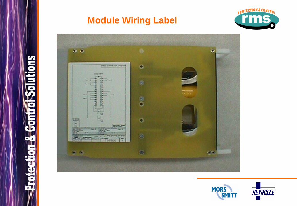
Module Wiring Label

Contact Ratings
Make & Carry Continuously 3,000 VA AC resistive with maximums of 660V & 12A 3,000 W DC resistive with maximums of 660V & 12A
Make & Carry for 3 Seconds 7,500 VA AC resistive with maximums of 660V & 30A 7,500 W DC resistive with maximums of 660V & 30A
AC Break Capacity 3,000 VA AC resistive with maximums of 660V & 12A
DC Break Capacity (Amps) Voltage
24V
48V
125V
250V
Resistive rating a
b 12 12
2 12
0.5 10
0.25 5
L/R=40ms
Maximum break
a b
12 30
1 15
0.25 5.5
0.15 3.5
1K operations(N3 Rating)
b
12
12
5
2.5
a = Without magnetic blowouts b = With magnetic blowouts

2HSMHigh Speed Multi Trip
<10ms operating time including bounce
High burden & low burden types
Latching or self reset contacts
Latching flags with large target window
Hand or electrical reset types
Any contact configuration up to 20 N/O
Heavy duty DC inductive load switching
Slug time delays for operation of series elements

2HSMSelection Chart
Maximum Contacts Magnetic
Blowouts Heavy Duty
Relay Type
Contact Flag Cut off Burden Element Size
Case M or B* 1
M or B* 2
2HSM502 SR HR Econ. Low A 2M28 3 5 B 2M28 9 13
2HSM504 HR Inst. Low B 2M28 10 13 2HSM506 ER HR Inst. Low B 2M28 9 12 2HSM508 H/ER Inst. Low B 2M28 9 12 2HSM509 H/ER HR Inst. Low B 2M28 9 12 2HSM512 SR HR Inst. High A 2M28 3 5
Econ. B 2M28 9 13 D 4M56 19 19
2HSM514 HR Inst. High B 2M28 10 13 D 4M56 20 20
2HSM516 ER HR Inst. High B 2M28 9 12 D 4M56 19 19
2HSM518 H/ER Inst. High B 2M28 9 12 D 4M56 19 19
2HSM519 H/ER HR Inst. High B 2M28 9 12 D 4M56 19 19
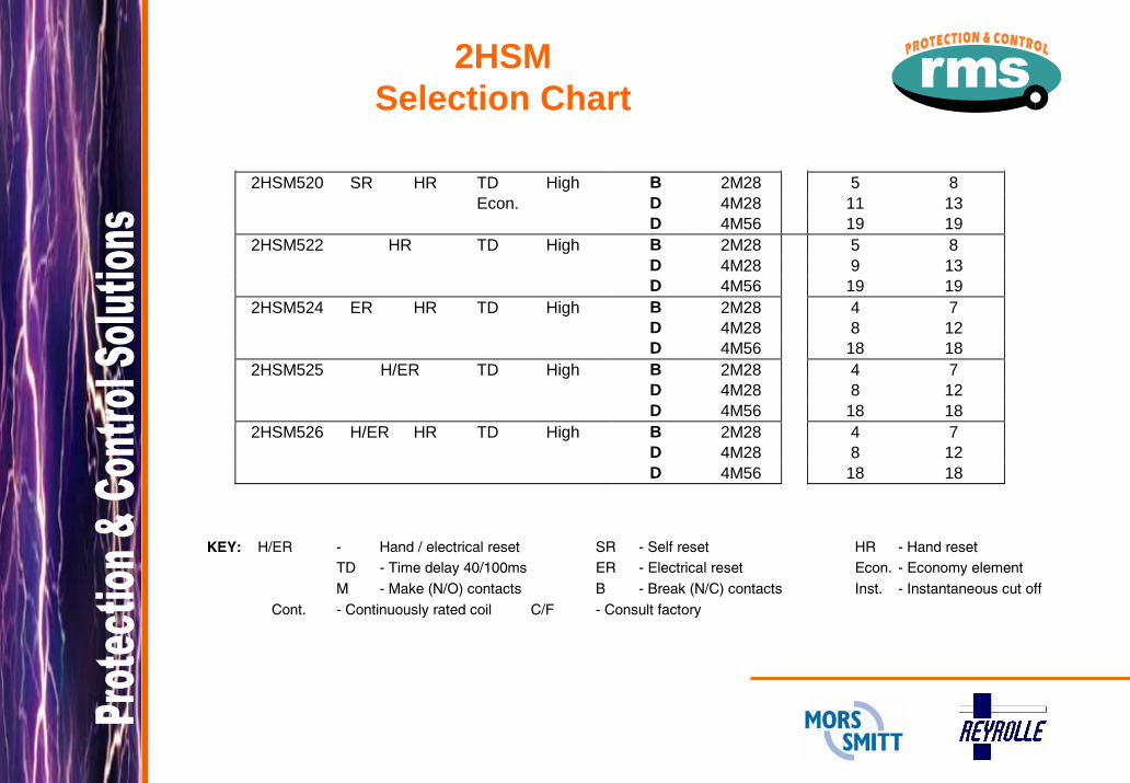
2HSMSelection Chart
2HSM520 SR HR TD High B 2M28 5 8 Econ. D 4M28 11 13 D 4M56 19 19
2HSM522 HR TD High B 2M28 5 8 D 4M28 9 13 D 4M56 19 19
2HSM524 ER HR TD High B 2M28 4 7 D 4M28 8 12 D 4M56 18 18
2HSM525 H/ER TD High B 2M28 4 7 D 4M28 8 12 D 4M56 18 18
2HSM526 H/ER HR TD High B 2M28 4 7 D 4M28 8 12 D 4M56 18 18
KEY: H/ER - Hand / electrical reset SR - Self reset HR - Hand reset TD - Time delay 40/100ms ER - Electrical reset Econ. - Economy element M - Make (N/O) contacts B - Break (N/C) contacts Inst. - Instantaneous cut off Cont. - Continuously rated coil C/F - Consult factory

2HSMAnti Bounce Buffers

2HSMElectrical Reset Mechanism

2HSM Ordering Codes
1 2 3 4 5 2HSM 1 RELAY FUNCTION Specify relay functional number from table 1. 2 ELEMENT SIZE A Size A Up to 2 elements in a 2M case B Size B Up to 1 element in a 2M case D Size D Up to 1 element in a 4M case 3 CONTACT DUTY 1 Heavy duty contacts – magnetic blowouts fitted 2 Heavy duty contacts 4 NOMINAL OPERATE VOLTAGE A 24V DC D 110V DC B 32V DC E 125V DC C 48V DC F 250V DC 5 CONTACT ARRANGEMENT Specify the number of “MAKES” followed by M; i.e. 10M Specify the number of “BREAKS” followed by B; i.e. 2B Specify the number of “CHANGEOVER” followed by C; i.e. 3C

Cross Reference Chart
6RJ Series High Speed Tripping Relays RMS Alstom Functional Description Contacts MATRIX Case
6RJ11 MVAJ11 Low burden self reset high speed trip relay 5 or 10 2HSM502 2M28 6RJ13 MVAJ13 Low burden hand reset high speed trip relay 5 or 10 2HSM504 2M28
6RJ15 MVAJ15 Low burden hand/electrical reset high speed trip relay 5 or 10 2HSM508 2M28
6RJ21 MVAJ21 High burden self reset high speed trip relay 5 or 10 2HSM512 2M28
6RJ23 MVAJ23 High burden hand reset high speed trip relay 5 or 10 2HSM514 2M28
6RJ25 MVAJ25 High burden hand/electrical reset high speed trip relay 5 or 10 2HSM519 2M28

6RMAuxiliary Relays
Instantaneous operate
Slug delay operate
Slug delay release
Latching or self reset flags with large target window
Hand or electrical reset types
Any contact configuration up to 20 N/O
Heavy duty DC inductive load switching
Electronic modules for extended time delays

6RMSelection Chart
Maximum Contacts 6R Element Part Numbers
Timing Function
Magnetic Blowouts
Heavy Duty
No Time Delay
Delay Release
Delay Operate Contact Flag Element
Size Case M or B* 1
M or B* 2
6RM201 6RM301 6RM401 SR NF A 2M28 4 6 B 2M28 10 13 D 4M56 20 20
6RM202 6RM302 6RM402 SR HR A 2M28 4 6 B 2M28 10 13 D 4M56 20 20
6RM203 6RM303 6RM403 SR A 2M28 4 6
B 2M28 10 13 D 4M56 20 20
6RM204 6RM304 6RM404 H/SR HR A 2M28 1SR / 1HR 2SR / 2HR
D 2M28 4SR / 4HR 6SR / 6HR

6RMSelection Chart
6RM206 - 6RM406 HR A 2M28 4 6 B 2M28 10 13 D 4M56 20 20
6RM208 - 6RM408 ER HR A 2M28 3 5
B 2M28 9 12 D 4M56 19 19
6RM210 - 6RM410 H/ER A 4M28 3 5
B 2M28 9 12 D 4M56 19 19
6RM211 - 6RM411 H/ER HR A 2M28 3 5
B 2M28 9 12 D 4M56 19 19
KEY: H/ER - Hand / electrical reset SR - Self reset HR - Hand reset H/SR - Hand / self reset ER - Electrical reset C/F - Consult factory M - Make (N/O) contacts B - Break (N/C) contacts NF - No flag *C/O - Changeover contacts may be specified but EACH C/O contact replaces 1.5 M or B cont

6RM Ordering Codes
1 2 3 4 5 6 7 6RM 1 RELAY FUNCTION Specify relay functional number from table 3. 2 ELEMENT SIZE A Size A Up to 2 elements in a 2M case B Size B Up to 1 element in a 2M case D Size D Up to 1 element in a 4M case 3 CONTACT DUTY 1 Heavy duty contacts – magnetic blowouts fitted 2 Heavy duty contacts 4 NOMINAL OPERATE VOLTAGE A 24V DC D 110V DC B 32V DC E 125V DC C 48V DC F 250V DC 5 CONTACT ARRANGEMENT Specify the number of “MAKES” followed by M; i.e. 10M Specify the number of “BREAKS” followed by B; i.e. 2B Specify the number of “CHANGEOVER” followed by C; i.e. 3C 6 FLAG OPERATION A Flag drops on energisation (Factory default) B Flag drops on de-energisation

Cross Reference Chart
6RA Series Auxiliary Flag Relays RMS Alstom Functional Description Contacts MATRIX Case
6RA11 MVAA11 Self reset auxiliary flag relay – 1 element 6 6RM202 2M28
6RA21 MVAA21 Self reset auxiliary flag relay – 2 element 6 x 2 6RM202 x2 2M28
6RA13 MVAA13 Hand reset auxiliary flag relay – 1 element 6 6RM206 2M28
6RA23 MVAA23 Hand reset auxiliary flag relay – 2 element 6 x 2 6RM206 x2 2M28
6RA15 MVAA15 Hand/Electrical reset auxiliary flag relay – 1 element 6 6RM210 2M28
1TMSupervision Relays
The 1TM Series Relays provide fail safe supervision of CB trip circuits.
Four models are available depending on the degree of supervision required & wiring configuration.

1TMSelection Chart
Model Number Supervision 1TM10 1TM11 1TM12 1TM13CB 52a contact Yes No Yes No CB 52b contact Yes No Yes No Trip supply Yes Yes Yes Yes Trip coil continuity Yes No Yes No Trip wiring continuity Yes No Yes No Trip relay circuit No No No Yes

1TM10System De-energised
+
RL1R1
R221 22
2
Trip RelayCB Aux Switch
52 - b
Trip Coil
Monitored circuits
52T
13 14
52 - a
13
5
24
6
RL1-1
RL1-2

1TMSupervision Relays
A significant safety feature is the fitting of internal resistors to limit the trip coil current to well below the circuit breaker trip coil operate current, should the relay be accidentally short circuited.

1TM10CB Open
+
RL1R1
R221 22
2
Trip RelayCB Aux Switch
52 - b
Trip Coil
52T
13 14
52 - a
13
5
24
6
RL1-1
RL1-2
Trip supplyTrip circuitTrip coil

1TM10CB Closing
+
RL1R1
R221 22
2
Trip RelayCB Aux Switch
52 - b
Trip Coil
52T
13 14
52 - a
13
5
24
6
RL1-1
RL1-2
Transient condition

1TM10CB Closed
+
RL1R1
R221 22
2
Trip RelayCB Aux Switch
52 - b
Trip Coil
52T
13 14
52 - a
13
5
24
6
RL1-1
RL1-2
Trip supplyTrip circuitTrip coil

1TM10CB Trip
+
RL1R1
R221 22
2
Trip RelayCB Aux Switch
52 - b
Trip Coil
52T
13 14
52 - a
13
5
24
6
RL1-1
RL1-2
Trip supplyTrip circuitTrip coil energized

1TM10CB Opening
+
RL1R1
R221 22
2
Trip RelayCB Aux Switch
52 - b
Trip Coil
52T
13 14
52 - a
13
5
24
6
RL1-1
RL1-2
Transient condition

1TM10CB Open
(Trip contact closed)
+
RL1R1
R221 22
2
Trip RelayCB Aux Switch
52 - b
Trip Coil
52T
13 14
52 - a
13
5
24
6
RL1-1
RL1-2
Trip supplyTrip circuitTrip coil

1TM10CB Open
(Trip contact open)
+
RL1R1
R221 22
2
Trip RelayCB Aux Switch
52 - b
Trip Coil
52T
13 14
52 - a
13
5
24
6
RL1-1
RL1-2
Trip supplyTrip circuitTrip coil

Cross Reference Chart
6RX Series Trip Circuit Supervision Relays RMS Alstom Functional Description Contacts MATRIX
6RX11 MVAX11 Trip relay supervision 2 1TM13
6RX12 MVAX12 Trip supply supervision 2 1TM11
6RX21 MVAX21 Trip circuit supervision 2 1TM10
6RX31 MVAX31 Trip circuit supervision – 3 element 2 1TM12

1TMOrdering Codes
1 2 31TM 1 RELAY FUNCTION
Specify relay functional number from table 5. 2 NOMINAL OPERATE VOLTAGE A 24V DC D 110V DC B 32V DC E 125V DC C 48V DC F 250V DC 3 CONTACT DUTY 1 Heavy duty contacts – magnetic blowouts fitted 2 Heavy duty contacts ELEMENT TEXT (Optional)
Element part number is used as the default

Transit Shipping Flag Wedge

Terminal Screws

Mounting
M4 Size
Self threading
Suit Rack or flush mounting

Semi Projection Mount Kit
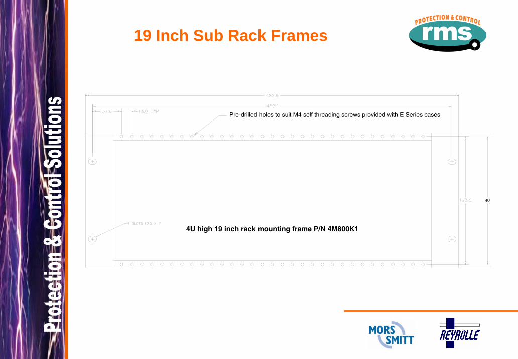
19 Inch Sub Rack Frames

6R MATRIXAdditional Information
Technical BulletinUser GuideAuto Cad Mounting DrawingsPrice & Availability
www.rmspl.com.au/6RMATRIX.htm
www.rmspl.com.au/6RM QUAD.htm
Test Manuals
www.rmspl.com.au/search.asp
Other Products
www.rmspl.com.au/Products.htm
Top Related