


Languages
Pages
Legal


Pulse Burst Radar
Level Transmitter
Model RX5RX5 software v2.1a
®
Installation and Operating Manual

58-601 Pulsar® Radar Transmitter
Read this Manual Before InstallingThis manual provides information on the Pulsar® Radartransmitter. It is important that all instructions are readcarefully and followed in sequence. The QuickStartInstallation instructions are a brief guide to the sequenceof steps for experienced technicians to follow wheninstalling the equipment. Detailed instructions areincluded in the Complete Installation section of this manual.
Conventions Used in this ManualCertain conventions are used in this manual to conveyspecific types of information. General technical material,support data, and safety information are presented in nar-rative form. The following styles are used for notes, cau-tions, and warnings.
NOTESNotes contain information that augments or clarifiesan operating step. Notes do not normally containactions. They follow the procedural steps to whichthey refer.
CautionsCautions alert the technician to special conditions thatcould injure personnel, damage equipment, or reducea component’s mechanical integrity. Cautions are alsoused to alert the technician to unsafe practices or theneed for special protective equipment or specific mate-rials. In this manual, a caution box indicates a poten-tially hazardous situation which, if not avoided, mayresult in minor or moderate injury.
WARNINGSWarnings identify potentially dangerous situations orserious hazards. In this manual, a warning indicates animminently hazardous situation which, if not avoided,could result in serious injury or death.
Safety MessagesThe Through-Air Radar system is designed for use inCategory II, Pollution Degree 2 installations. Follow allstandard industry procedures for servicing electrical andcomputer equipment when working with or around highvoltage. Always shut off the power supply before touchingany components. Although high voltage is not present inthis system, it may be present in other systems.
Electrical components are sensitive to electrostatic dis-charge. To prevent equipment damage, observe safetyprocedures when working with electrostatic sensitivecomponents.
Low Voltage DirectiveFor use in Installations Category II, Pollution Degree 2.If equipment is used in a manner not specified by themanufacturer, protection provided by equipment may beimpaired.
This device complies with Part 15 of the FCC rules.Operation is subject to the following two conditions:(1) This device may not cause harmful interference, and(2) This device must accept any interference received,including interference that may cause undesired operation.
FCC ID: LPN R95Any unauthorized changes or modifications not expresslyapproved by the party responsible for compliance couldvoid user’s authority to operate this equipment.
WARNING! Explosion hazard. Do not connect or dis-connect designs rated Explosion-proof or Non-incendiveunless power has been switched off and/or the area isknown to be non-hazardous
Notice of Copyright and LimitationsMagnetrol® & Magnetrol® logotype and Pulsar®
are registered trademarks of Magnetrol® International,Incorporated.
Copyright © 2011 Magnetrol® International,Incorporated. All rights reserved.
Performance specifications are effective with date of issueand are subject to change without notice. MAGNETROLreserves the right to make changes to the productdescribed in this manual at any time without notice.MAGNETROL makes no warranty with respect to theaccuracy of the information in this manual.
WarrantyAll MAGNETROL electronic level and flow controls arewarranted free of defects in materials or workmanship forone full year from the date of original factory shipment.
If returned within the warranty period; and, upon facto-ry inspection of the control, the cause of the claim isdetermined to be covered under the warranty; then,MAGNETROL will repair or replace the control at no costto the purchaser (or owner) other than transportation.
MAGNETROL shall not be liable for misapplication,labor claims, direct or consequential damage or expensearising from the installation or use of equipment. Thereare no other warranties expressed or implied, except spe-cial written warranties covering some MAGNETROLproducts.
Quality AssuranceThe quality assurance system in place at MAGNETROLguarantees the highest level of quality throughout thecompany. MAGNETROL is committed to providingfull customer satisfaction both in quality products andquality service.
The MAGNETROL quality assurancesystem is registered to ISO 9001affirming its commitment to knowninternational quality standards providingthe strongest assurance of product/servicequality available.

58-601 Pulsar® Radar Transmitter
Table of Contents
1.0 QuickStart Installation1.1 Getting Started..........................................................4
1.1.1 Equipment and Tools .....................................41.1.2 Configuration Information.............................5
1.2 QuickStart Mounting................................................61.2.1 Antenna .........................................................61.2.2 Transmitter.....................................................6
1.3 QuickStart Wiring ....................................................61.4 QuickStart Configuration .........................................7
2.0 Complete Installation2.1 Unpacking ................................................................92.2 Electronic Discharge (ESD) Handling Procedure......92.3 Before You Begin.....................................................10
2.3.1 Site Preparation ............................................102.3.2 Equipment and Tools ...................................102.3.3 Operational Considerations..........................10
2.3.3.1 Maximum Distance...............................112.3.3.2 Minimum Distance...............................112.3.3.3 Problematic Applications;
GWR Alternative ..................................112.4 Mounting................................................................12
2.4.1 Installing the Antenna ..................................122.4.1.1 Location................................................122.4.1.2 Beam Angle...........................................122.4.1.3 Obstructions .........................................132.4.1.4 Nozzles..................................................132.4.1.5 Standpipes and Stillwells .......................14
2.4.2 Installing the Transmitter .............................142.4.2.1 Orientation ...........................................142.4.2.2 Initial Installation..................................152.4.2.3 Poor Signal Quality...............................15
2.5 Wiring ....................................................................162.5.1 General Purpose or Non-Incendive ..............162.5.2 Intrinsically Safe ...........................................162.5.3 Explosion Proof............................................17
2.6 Configuring the Transmitter....................................182.6.1 Operating Parameters ...................................182.6.2 Setting Up for Shop Configuration ..............182.6.3 Transmitter Display and Keypad ..................182.6.4 Password Protection (Default = 0)................192.6.5 Menu: Step-By-Step Procedure.....................20
2.6.5.1 Radar Transmitter Menu Table..............212.7 Configuration Using HART®..................................25
2.7.1 Connections .................................................252.7.2 Display Menu...............................................252.7.3 HART Revision Table ..................................25
2.7.3.1 Model RX5 ...........................................252.7.4 HART Menu................................................26
3.0 Reference Information3.1 Description .............................................................273.2 Theory of Operation...............................................27
3.2.1 Pulse Burst Radar .........................................273.2.2 Equivalent Time Sampling ...........................28
3.3 Troubleshooting ......................................................293.3.1 System Problems ..........................................293.3.2 Error Messages .............................................30
3.4 Agency Approvals....................................................323.4.1 Agency Drawing and Entity Parameters .......33
3.5 Parts ........................................................................343.5.1 Replacement Parts ........................................343.5.2 Recommended Spare Parts ...........................34
3.6 Specifications ..........................................................353.6.1 Functional – Transmitter ..............................353.6.2 Performance .................................................363.6.3 O-ring (seal) Selection Chart........................363.6.4 Functional – Dielectric Rod/Horn ...............373.6.5 Antenna Pressure-Temperature Ratings ........373.6.6 Physical ........................................................38
3.7 Model Numbers ......................................................393.7.1 PULSAR Radar Transmitter .........................393.7.2 Radar Antennas – Dielectric Rod .................403.7.3 Radar Antennas – Horn ...............................41
Glossary .........................................................................42Model RX5 Configuration Data Sheet..........................45
Pulsar® Pulse Burst Radar Level Transmitter

4 58-601 Pulsar® Radar Transmitter
1.0 QuickStart Installation
The QuickStart Installation procedures provide the keysteps for mounting, wiring, and configuring the PULSARradar level transmitter. These procedures are intended forexperienced installers of electronic level measurementinstruments. See Complete Installation, Section 2.0, fordetailed installation instructions.
1.1 Getting Started
Before beginning the QuickStart Installation procedures,have the right equipment, tools, and information available.
1.1.1 Equipment and Tools
No special tools are needed. The following items arerecommended:
• Threaded antenna and transmitter . . . . . . 2" (50 mm)
• Transmitter/antenna connection. . . . . . . . 13⁄4" (44 mm)
• Transmitter adjustment . . . . . . . . . . . . . . 11⁄8" (28 mm),3⁄32" (2.5 mm) Hex
• Torque wrench . . . . . . . . . . . . . . . . . . . . . highly desirable
• Flat-blade screwdriver
• Digital multimeter or volt/ammeter . . . . . Optional
• 24 VDC (23 mA) power supply. . . . . . . . Optional

558-601 Pulsar® Radar Transmitter
1.1.2 Configuration Information
Some key information is needed to configure the PULSARradar transmitter. Complete the following operating param-eters table before beginning configuration.
NOTE: The transmitter will already be configured if this information wasprovided with the order.
Display Question Answer
Units What units of measurement will beused? _____________
Antenna What type of antenna is being used?Type Select first 7 digits of Model number.
(See nameplate on side of antenna) _____________
Antenna What is maximum nozzle length thatExtension the antenna can be used?
Select last 3 digits of Model number.(See nameplate on side of antenna) _____________
Antenna Is the antenna mounting NPT, BSP,Mount or flanged? _____________
Sensor What is the distance from the top (100%)Offset of the tank and the Sensor Reference
point (bottom of NPT thread, top of BSPthread, or face of flange?) _____________
Tank Top Is the Tank Top Flat, Horizontal Cylinder,Dome, Irregular or other (non-metallic)? _____________
Tank What is the tank height? _____________Height NOTE: Sensor Offset + Tank Height =
Distance from processconnection to tank bottom
Blocking What is the distance from SensorReference point to Maximum Level?Maximum level should never be lessthan 2" (50 mm) from bottom of antenna. _____________
Level Is there a region at the very bottom of theOffset vessel that cannot be measured due to
heating coils, angle tank bottom, etc.? _____________
Dielectric What is the dielectric of the processmedium? _____________
Turbulence Is turbulence a consideration? _____________
Rate of What is the maximum rate the levelChange will rise or fall? _____________
Foam Will there be foam on the surface? _____________
Set What is the 0% reference point for the4.0 mA 4.0 mA value? _____________
Set What is the 100% reference point for20.0 mA the 20.0 mA value? _____________
6 58-601 Pulsar® Radar Transmitter
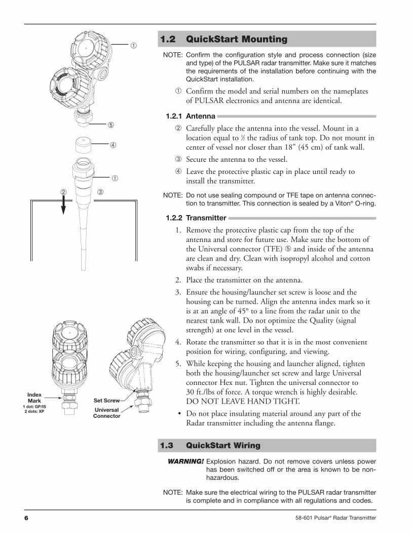
1.2 QuickStart Mounting
NOTE: Confirm the configuration style and process connection (sizeand type) of the PULSAR radar transmitter. Make sure it matchesthe requirements of the installation before continuing with theQuickStart installation.
Confirm the model and serial numbers on the nameplatesof PULSAR electronics and antenna are identical.
1.2.1 Antenna
Carefully place the antenna into the vessel. Mount in alocation equal to 1⁄2 the radius of tank top. Do not mount incenter of vessel nor closer than 18" (45 cm) of tank wall.
Secure the antenna to the vessel.
Leave the protective plastic cap in place until ready toinstall the transmitter.
NOTE: Do not use sealing compound or TFE tape on antenna connec-tion to transmitter. This connection is sealed by a Viton® O-ring.
1.2.2 Transmitter
1. Remove the protective plastic cap from the top of theantenna and store for future use. Make sure the bottom ofthe Universal connector (TFE) and inside of the antennaare clean and dry. Clean with isopropyl alcohol and cottonswabs if necessary.
2. Place the transmitter on the antenna.
3. Ensure the housing/launcher set screw is loose and thehousing can be turned. Align the antenna index mark so itis at an angle of 45° to a line from the radar unit to thenearest tank wall. Do not optimize the Quality (signalstrength) at one level in the vessel.
4. Rotate the transmitter so that it is in the most convenientposition for wiring, configuring, and viewing.
5. While keeping the housing and launcher aligned, tightenboth the housing/launcher set screw and large Universalconnector Hex nut. Tighten the universal connector to30 ft./lbs of force. A torque wrench is highly desirable.DO NOT LEAVE HAND TIGHT.
• Do not place insulating material around any part of theRadar transmitter including the antenna flange.
1.3 QuickStart Wiring
WARNING! Explosion hazard. Do not remove covers unless powerhas been switched off or the area is known to be non-hazardous.
NOTE: Make sure the electrical wiring to the PULSAR radar transmitteris complete and in compliance with all regulations and codes.
Set Screw
UniversalConnector
IndexMark
1 dot: GP/IS2 dots: XP

758-601 Pulsar® Radar Transmitter
1. Remove the cover of the wiring compartment.
2. Attach a conduit fitting and mount the conduit plug in thespare opening. Pull the power supply wire through the con-duit fitting.
3. Connect shield to an earth ground at power supply andleave floating at the transmitter.
4. Connect the positive supply wire to the (+) terminal and thenegative supply wire to the (-) terminal. For ExplosionProof Installations, see Wiring, Section 2.5.3.
5. Replace the cover and tighten.
1.4 QuickStart Configuration
The Radar transmitter comes factory-calibrated and can beconfigured in minutes for specific applications. Bench con-figuration provides a convenient and efficient way to set upthe transmitter before going to the tank site to complete theinstallation (disregard Fault messages due to unattachedantenna). The minimum configuration instructions follow.Use the information from the operating parameters tablebefore beginning configuration. See ConfigurationInformation, Section 1.1.2.
1. Power-up the transmitter.
Upon initial start-up, NO FALSE TARGET REJECTIONerror message will be displayed. Once in the vessel theFALSE TARGET routine must be run for proper operation.During normal operation the display changes every 5 sec-onds to show one of the four measured values: Level,Quality, %Output, and Loop.
2. Remove the cover of the electronic compartment.
3. Use the Up or Down Arrow ( ) keys to move from onestep of the configuration program to the next step.
4. Press the Enter Arrow ( ) key. If a PASSWORD is active,enter it here. The default=0 (no password necessary). Thelast character in the first line of the displaychanges to an exclamation point (!).
5. Use the Up or Down Arrow ( ) keys to increase ordecrease the value in the display or to scroll through thechoices.
6. Press the Enter Arrow ( ) key to accept a value and moveto the next step of the configuration program.
Units!xxx
EnterDown
Up
Red (+)Black (-)
(+)
(-)

8 58-601 Pulsar® Radar Transmitter
Select the Units of measurementfor the levelreadout (cm, inches, meters, feet).
Select the Antenna Type to be usedas printed on the transmitter name-plate; first 7 digits of model number.
Select the Antenna Extension tobe used as printed on the antennanameplate; last 3 digits of modelnumber.
Select the type of AntennaMounting to be used.
Enter the Sensor Offset value; thedistance from the top (100%) pointof the vessel to the SensorReference point (bottom of an NPTthread, top of a BSP thread, face ofa flange).
Select the type of Tank Top; choic-es are Flat, Horizontal cylinder,Dome, Irregular, or Other (non-metallic).
Enter the exact Tank Height; inac-curate values will create inaccuratelevel readings.
Enter the Blocking Distance; thedistance close to the antennawhere measurement is unreliabledue to antenna ringing.Minimum value = antenna length +2" (50 mm)
Enter the Level Offset; the distanceat the bottom of the vessel wheremeasurement may be unreliabledue to heating coils, irregular bot-tom, etc.
Select the proper Dielectric rangefor the process medium.
Select the value of Turbulence thatcorresponds to the application.
Select the Rate of Change valuethat corresponds to the maximumrate the level will rise or fall.
Select the Foam value that corre-sponds to the application.
Examine the list of reflectionsdetected by the transmitter toensure the actual level reflection ispresent. It may be necessary torotate the launcher for optimumperformance.
Run the Target Rejection routineby choosing the correct LEVELthereby cancelling all false reflectionsin the vessel; ideally with tank empty.
Enter the minimum level value (0%)for the 4 mA point.
Enter the maximum level (100%) forthe 20 mA point.
Units(select)
Antna Typ(select)
Antna Ext(select)
SnsrOfstxxxx
Tank Top(select)
Tank Htxxxx
BlockDisxxxx
Dielectrc(select)
Turbulnc(select)
RateChg(select)
Foam(select)
Targets
TargRej(status)
Set 4mAxx.x
Set 20mAxx.x
Sensor Offset
Tank Height
BlockingDistance
LevelOffset
142 3
9
10
11 12
13
14 15
16
17
7
8 6
5
The following configuration entries are the minimumrequired for configuration. The default password is 0.
Antna Mnt(select)
1
2
3
4
5
6
7
8
9
10
11
12
13
14
15
16
17
LevlOfstxxx.x
Note: Clear all diagnostic messages upon completionof configuration. See screens 41 and 42 onpage 24.

958-601 Pulsar® Radar Transmitter
2.0 Complete Installation
This section provides detailed procedures for properlyinstalling, configuring, and, as needed, troubleshooting thePULSAR Radar Level Transmitter.
2.1 Unpacking
Unpack the instrument carefully. Make sure all componentshave been removed from the packing material. Check all thecontents against the packing slip and report any discrepanciesto the factory.
Before proceeding with the installation, do the following:
• Inspect all components for damage. Report any damage tothe carrier within 24 hours.
• Make sure the nameplate model number on the antenna andtransmitter agree with the packing slip and purchase order.
• Record the model and serial numbers for future referencewhen ordering parts.
2.2 Electrostatic Discharge (ESD)Handling Procedure
MAGNETROL electronic instruments are manufactured tothe highest quality standards. These instruments use electroniccomponents that may be damaged by static electricity presentin most work environments.
The following steps are recommended to reduce the risk ofcomponent failure due to electrostatic discharge.
• Ship and store circuit boards in anti-static bags. If an anti-static bag is not available, wrap the board in aluminum foil.Do not place boards on foam packing materials.
• Use a grounding wrist strap when installing and removingcircuit boards. A grounded workstation is recommended.
• Handle circuit boards only by the edges. Do not touchcomponents or connector pins.
• Make sure that all electrical connections are completelymade and none are partial or floating. Ground all equip-ment to a good, earth ground
WARNING! Potential electrostatic charging hazard. Do not rubwith dry cloth.

10 58-601 Pulsar® Radar Transmitter
2.3 Before You Begin
2.3.1 Site Preparation
Each PULSAR Radar transmitter is built to match the specificphysical specifications of the required installation. Make surethe antenna connection is correct for the threaded or flangedmounting on the vessel or tank where the transmitter willbe placed. See Mounting, Section 2.4.
Make sure that the wiring between the power supply andRadar transmitter are complete and correct for the type ofinstallation.
When installing the Radar transmitter in a general purposeor hazardous area, all local, state, and federal regulationsand guidelines must be observed. See Wiring, Section 2.5.
2.3.2 Equipment and Tools
No special tools are needed. The following items arerecommended:
• Threaded antenna and transmitter . . . . . . 2" (50 mm)
• Transmitter/antenna connection. . . . . . . . 13⁄4" (44 mm)
• Transmitter adjustment . . . . . . . . . . . . . . 11⁄8" (28 mm),3⁄32" (2.5 mm) Hex
• Torque wrench . . . . . . . . . . . . . . . . . . . . . highly desirable
• Flat-blade screwdriver
• Digital multimeter or volt/ammeter . . . . . Optional
• 24 VDC (23 mA) power supply. . . . . . . . Optional
2.3.3 Operational Considerations
Radar applications are characterized by three basic conditions;Dielectric, Distance (measuring range) and Disturbances(turbulence, foam, false targets, multiple reflections and rateof change). The PULSAR Radar transmitter is offered withthree antenna configurations—Dielectric Rod, 4" (DN100)Horn and 6" (DN150) Horn. Ideally, the 6" (DN150)Horn antenna should be used to ensure the best possibleperformance in all operational conditions.
1158-601 Pulsar® Radar Transmitter
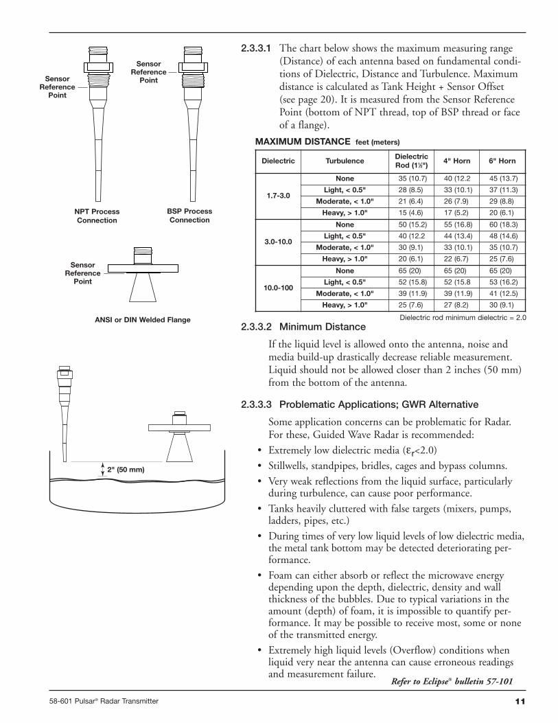
2.3.3.1 The chart below shows the maximum measuring range(Distance) of each antenna based on fundamental condi-tions of Dielectric, Distance and Turbulence. Maximumdistance is calculated as Tank Height + Sensor Offset(see page 20). It is measured from the Sensor ReferencePoint (bottom of NPT thread, top of BSP thread or faceof a flange).
2.3.3.2 Minimum Distance
If the liquid level is allowed onto the antenna, noise andmedia build-up drastically decrease reliable measurement.Liquid should not be allowed closer than 2 inches (50 mm)from the bottom of the antenna.
2.3.3.3 Problematic Applications; GWR Alternative
Some application concerns can be problematic for Radar.For these, Guided Wave Radar is recommended:
• Extremely low dielectric media (εr<2.0)
• Stillwells, standpipes, bridles, cages and bypass columns.
• Very weak reflections from the liquid surface, particularlyduring turbulence, can cause poor performance.
• Tanks heavily cluttered with false targets (mixers, pumps,ladders, pipes, etc.)
• During times of very low liquid levels of low dielectric media,the metal tank bottom may be detected deteriorating per-formance.
• Foam can either absorb or reflect the microwave energydepending upon the depth, dielectric, density and wallthickness of the bubbles. Due to typical variations in theamount (depth) of foam, it is impossible to quantify per-formance. It may be possible to receive most, some or noneof the transmitted energy.
• Extremely high liquid levels (Overflow) conditions whenliquid very near the antenna can cause erroneous readingsand measurement failure.
Dielectric TurbulenceDielectricRod (11⁄2")
4" Horn 6" Horn
1.7-3.0
None 35 (10.7) 40 (12.2 45 (13.7)
Light, < 0.5" 28 (8.5) 33 (10.1) 37 (11.3)
Moderate, < 1.0" 21 (6.4) 26 (7.9) 29 (8.8)
Heavy, > 1.0" 15 (4.6) 17 (5.2) 20 (6.1)
3.0-10.0
None 50 (15.2) 55 (16.8) 60 (18.3)
Light, < 0.5" 40 (12.2 44 (13.4) 48 (14.6)
Moderate, < 1.0" 30 (9.1) 33 (10.1) 35 (10.7)
Heavy, > 1.0" 20 (6.1) 22 (6.7) 25 (7.6)
10.0-100
None 65 (20) 65 (20) 65 (20)
Light, < 0.5" 52 (15.8) 52 (15.8 53 (16.2)
Moderate, < 1.0" 39 (11.9) 39 (11.9) 41 (12.5)
Heavy, > 1.0" 25 (7.6) 27 (8.2) 30 (9.1)
MAXIMUM DISTANCE feet (meters)
2" (50 mm)
SensorReference
Point
SensorReference
Point
SensorReference
Point
NPT ProcessConnection
BSP ProcessConnection
ANSI or DIN Welded Flange
Refer to Eclipse® bulletin 57-101
Dielectric rod minimum dielectric = 2.0

12 58-601 Pulsar® Radar Transmitter
2.4 Mounting
The PULSAR Radar transmitter can be mounted to a vesselusing a variety of process connections. Generally, either athreaded or flanged connection is used.
2.4.1 Installing the Antenna
Before installing, make sure:
• Model and Serial numbers on the nameplates of the PULSARantenna and transmitter are identical.
• Process temperature, pressure, dielectric, turbulence anddistance are within the antenna specifications for theinstallation.
• Rod of a Dielectric Rod antenna is protected from bendingor breaking; there is no metal sub-structure.
• Insulating material is not placed around any part of theRadar transmitter including the antenna flange.
• Protective cap is kept on the antenna if the transmitter is tobe installed at a later time.
• Antenna is being mounted in the optimal location. See fol-lowing sections: Location, Beam Angle, Obstructions andNozzles for specific information.
• If the liquid level is allowed onto the antenna, noise andmedia buildup drastically decrease reliable measurement.Liquid should not be allowed closer than 2 inches (50 mm)from the bottom of the antenna.
2.4.1.1 Location
Ideally, the Radar transmitter should be mounted providingan unobstructed signal path to the liquid surface where itshould illuminate (with microwave energy) the largest,possible surface area. See Section 2.4.1.2, Beam Angle.Unavoidable obstacles will produce reflections that must beminimized during field configuration. See Section 2.6.5.1,Target Rejection. Mount in a location equal to 1⁄2 the radiusof tank top. Do not mount in center of vessel nor closerthan 18" (45 cm) of tank wall.
2.4.1.2 Beam Angle
The various antenna designs exhibit different beam patterns.Ideally, the beam pattern should illuminate the maximumliquid surface with a minimum striking other objects in thevessel including the tank wall. Use these drawings to deter-mine the optimum installation location.
1/2Radius
> 18"(45 cm)
D
WW
∝ ∝
Beam Spread, W @-3dB; ft (m)
Antenna
Beam Angle(∝)
Dielectric Rod
25°
4" Horn
25°
6" Horn
17°
Distance, D
10 (3) 4.5 (1.37) 4.5 (1.37) 3.0 (0.91)
20 (6) 8.9 (2.71) 8.9 (2.71) 6.0 (1.83)
30 (9) 13.3 (4.05) 13.3 (4.05) 9.0 (2.74)
40 (12) 17.8 (5.43) 17.8 (5.43) 12.0 (3.66)
50 (15) 22.2 (6.77) 22.2 (6.77) 15.0 (4.57)
60 (18) 26.6 (8.11) 26.6 (8.11) 18.0 (5.49)
65 (20) 28.9 (8.81) 28.9 (8.81) 19.5 (5.95)

1358-601 Pulsar® Radar Transmitter
2.4.1.3 Obstructions
Almost any object that falls within the beam pattern will causereflections that may be misinterpreted as a false liquid level.Although PULSAR has a powerful False Target Rejectionroutine, all possible precautions should be taken to minimizefalse target reflections with proper installation and orientation.
2.4.1.4 Nozzles
Improper installation in a nozzle creates “ringing” that willadversely affect measurement. The antenna should always bemounted so the active section of the antenna is a minimumof 0.5" (12mm) outside the nozzle. Antenna extensions areoffered to allow the PULSAR transmitter to work reliably innozzles with “L” dimensions of 1" (25 mm), 4" (100mm),8" (200mm) or 12" (300mm). Standard antennas (noextension) are shown below for reference. See Section 3.6.5for dimensional drawings of all antenna designs includingnozzle extensions.
0.50" (13 mm)Minimum
2" (50 mm)Minimum Diameter
Dielectric Rod Antenna
Coupling
2" (50 mm)
2" (50 mm)
8" (200 mm)
Horn Antenna
" L " Dimension
2.8(55)
0.68 (17) ThreadEngagement
AC
B
D∅
3(76)
H
∅Aperture
Model #Antenna
Extension(maximum “L”
dimension)
All All BSP
8th Digit Dim A Dim B Dim C
0 1" (25 mm) 2.2 (56) 11.1 (282) 3.0 (76)
1 4" (100 mm ) 5.1 (130) 14.0 (356) 5.9 (150)
2 8" (200 mm) 9.1 (231) 18.0 (457) 9.9 (251)
3 12" (300 mm) 13.1 (333) 22.0 (559) 13.9 (353)
Antenna Extension O.D.Dimension D
TFE Rod ∅ 1.625 (41)
PP Rod ∅ 1.50 (38)
All-PlasticRod
∅ 1.625 (41)
Model #Antenna
Extension(maximum “L”
dimension)
3" Horn 4" Horn 6" Horn
8th Digit Dim H Dim H Dim H
0 1" (25 mm) 2.7 (51)
1 4" (100 mm )
N/A
4.6 (117)
2 8" (200 mm) 8.4 (213) 8.3 (211)
3 12" (300 mm) 12.4 (315) 12.4 (315)
Aperture 2.95" (75 mm) 3.75" (95 mm) 5.75" (146 mm)
DIELECTRIC RODS
HORNS

14 58-601 Pulsar® Radar Transmitter
2.4.1.5 Standpipes and Stillwells
PULSAR can be mounted in a standpipe or stillwell butcertain considerations should be given:
• Metal stillwells only: Sizes 3–8 inches (80–200 mm).
• Diameter must be consistent throughout length; no reducers.
• Use only horn antennas sized to pipe ID; 3–6"(80–150mm); 8" pipe can use a 6" horn.
• Stillwell length must cover complete range of measurement(i.e., liquid must be in stillwell).
• Welds should be smooth.
• Vents: holes <0.5" diameter, slots <0.5" width.
• If an isolation valve is used, it must be a full port ball valvewith an I.D. equal to the pipe diameter.
• Bridles/Bypass Installations: The launcher (index mark)should be rotated 90° from process connections.
• Configuration must include an entry for PIPE I.D.See Section 2.6.5.1, Item 35- PIPE I.D.
• There will be some increased dielectric sensitivity; systemGAIN will be reduced when PIPE ID >0.
2.4.2 Installing the Transmitter
• Remove the protective plastic cap from the top of antenna.
• Carefully place the transmitter on the antenna.
• Rotate the transmitter to face the most convenient directionfor wiring, configuration and viewing. Do not tighten theuniversal connector (large hex nut) nor the set screw on thehousing base. The transmitter launcher must be orientedproperly for optimal performance.
• Do not place insulating material around any part of theradar transmitter including the antenna flange.
2.4.2.1 Orientation
The PULSAR transmitter utilizes a linearly polarized,microwave beam that can be rotated to improve its perform-ance. Proper orientation can minimize unwanted targetreflections, decrease sidewall reflections (multipath) andmaximize direct reflections from the liquid surface. The indexmark located on the side of the launcher is oriented in thesame direction as the polarization.
The index mark is also present for reference(1 dot: GP/IS or2 dots: XP). The launcher is considered to be at 0° whenthe index mark is closest to the tank wall.
Set Screw
UniversalConnector
IndexMark
1 dot: GP/IS2 dots: XP
IndexMark
index mark
45°
Polarization Pattern
PULSAR Mounted in Stillwell (Bridle)

1558-601 Pulsar® Radar Transmitter
2.4.2.2 Initial Installation
Ideally, the transmitter should be mounted half the radiusfrom the tank wall. Align the index mark so it is at an angleof 45 degrees to a line from the radar unit to the nearesttank wall. For horizontal cylindrical vessels, align thelauncher (index mark) so it is facing along the long axis ofthe vessel. Do not optimize the Quality (signal strength) atone level in the vessel. Once properly oriented, tighten setscrews and Universal connector (30 ft-lbs of force).
A transmitter mounted within 18" (45 cm) of a tank wallmay demand orientation adjustments to limit multipathand optimize performance. See Section 2.4.2.3 Signal Loss.
NOTE: ALWAYS RUN THE TARGET REJECTION ROUTINE AFTERMAKING CHANGES TO MENU CHOICES (Antenna Type,Antenna Mount, Sensor Offset, Tank Height, BlockingDistance, Dielectric, Turbulence, Rate Change, Foam) orwhen launcher is repositioned.
2.4.2.3 Poor Signal Quality
Poor signal quality has many potential causes. Following aretwo initial areas for investigation.
Launcher Orientation: Initial launcher orientation is always45 degrees (see Sections 2.4.1 & 2.4.2). In tall vessels andwhen antenna is mounted close to the tank wall, improve-ment in signal quality may be attained by rotating thelauncher to 90 degrees.
Signal Loss: If the Level signal is lost repeatedly at a specificpoint in the vessel, it is usually a symptom that multipath(side-wall reflections) are causing cancellation by returningto the transmitter exactly 180° out of phase with the Levelsignal. Utilize the following procedure:
• Go to transmitter screen #4 which shows both Level andsignal Quality.
• Bring the Level up (or down) to the exact point where thesignal is repeatedly lost. Monitor the Quality value as thispoint is being approached. The Quality value will degradeto a low point before it begins to increase.
• At the point of poorest Quality, loosen both the Universalconnector and the set screw. Slowly rotate the launcherclockwise approximately 10–20° (the transmitter can berotated independently). Allow the unit to stabilize forapproximately 1 minute. Repeat this process until the signalQuality value is optimized.
• Without disturbing the position of the launcher, positionthe transmitter head back to its most convenient location.
• Tighten both the Universal connector (30 ft-lbs of force) andLauncher set screw.
1/2 Radius
Launch
er
Index
mar
k
(facin
g45°)
45°
90°
Top ViewMounted 1⁄2 radius
Set Screw
UniversalConnector

16 58-601 Pulsar® Radar Transmitter
Red (+)Black (-)
(+)
(-)
NOTE: ALWAYS RUN THE TARGET REJECTION ROUTINE AFTERMAKING CHANGES TO MENU CHOICES (Antenna Type,Antenna Mount, Sensor Offset, Tank Height, BlockingDistance, Dielectric, Turbulence, Rate Change, Foam) orwhen launcher is repositioned.
2.5 Wiring
Caution The PULSAR Radar transmitter operates at voltages of16–36 VDC (GP), 16-28.6 VDC (IS) and 16–36 VDC (XP).Higher voltage will damage the transmitter.
Wiring between the power supply and the Radar transmittershould be made using 18–22 AWG shielded twisted pairinstrument cable. Within the transmitter enclosure, con-nections are made to the terminal strip and the groundconnections. The directions for wiring the Radar transmitterdepend on the application:
• General Purpose or Non-incendive (Cl I, Div. 2)
• Intrinsically Safe
• Explosion Proof
NOTE: For ATEX/IEC installation guidelines refer to bulletin BE 58-601.
WARNING! Explosion hazard. Do not remove covers unless powerhas been switched off or the area is known to be non-hazardous.
2.5.1 General Purpose or Non-incendive (Cl I, Div. 2)
A general purpose installation does not have flammablemedia present. Areas rated non-incendive (Cl I, Div. 2) haveflammable media present only under abnormal conditions.No special electrical connections are required. If flammablemedia is contained in the vessel, the transmitter must beinstalled per Cl I, Div. 1 standards of area classification.
To install General Purpose or Non-incendive wiring:
1. Remove the cover to the wiring compartment of the trans-mitter. Install the conduit plug in the unused opening.
2. Install a conduit fitting and pull the supply wires.
3. Connect shield to an earth ground at power supply andleave floating at the transmitter.
4. Connect an earth ground wire to the nearest green groundscrew per local electrical code (not shown in illustration).
5. Connect the positive supply wire to the (+) terminal andthe negative supply wire to the (-) terminal.
6. Replace cover to the wiring compartment of transmitter.
2.5.2 Intrinsically Safe
An intrinsically safe (IS) installation potentially has flam-mable media present. An approved IS barrier must beinstalled in the non-hazardous (safe) area.

1758-601 Pulsar® Radar Transmitter
To install Intrinsically Safe wiring:1. Make sure the IS barrier is properly installed in the safe
area (refer to local plant or facility procedures). Completethe wiring from the barrier to the Radar transmitter.
2. Remove the cover to the wiring compartment of the trans-mitter. Install the conduit plug in the unused opening.
3. Install a conduit fitting and pull the supply wires.
4. Connect shield to an earth ground at power supply andleave floating at the transmitter.
5. Connect an earth ground wire to the nearest green groundscrew (not shown in illustration).
6. Connect the positive supply wire to the (+) terminal andthe negative supply wire to the (-) terminal.
7. Replace the cover to the wiring compartment of thetransmitter.
2.5.3 Explosion Proof
Explosion Proof (XP) is a method of designing equipmentfor installation in hazardous areas. A hazardous location isan area in which flammable gases or vapors are, or maybe, present in the air in quantities sufficient to produceexplosive or ignitable mixtures. The wiring for the trans-mitter must be contained in Explosion Proof conduitextending into the safe area. Due to the specialized designof the Radar transmitter, no Explosion Proof conduit fit-ting (EY seal) is required within 18" of the transmitter.An Explosion Proof conduit fitting (EY seal) is requiredbetween the hazardous and safe areas.
To install Explosion Proof wiring:1. Install Explosion Proof conduit from the safe area to the
conduit connection of the Radar transmitter (refer to localplant or facility procedures).
2. Remove the cover to the wiring compartment of thetransmitter.
3. Connect shield to an earth ground at the power supplyand leave floating at the transmitter.
4. Connect an earth ground wire to the nearest greenground screw per local electrical code (not shown inillustration).
5. Connect the positive supply wire to the (+) terminal andthe negative supply wire to the (-) terminal.
6. Replace the cover to the wiring compartment of thetransmitter.
Red (+)Black (-)
(+)
(-)
18 58-601 Pulsar® Radar Transmitter
2.6 Configuring the Transmitter
The Radar transmitter comes factory-calibrated and can beconfigured in minutes for specific applications.
Before configuring the transmitter, collect the operatingparameters information. Then, power-up the transmitteron the bench and follow through the step-by-step proce-dures for the menu-driven transmitter display. Informationon configuring the transmitter using a HART communica-tor is given in Configuration Using HART (Section 2.7).
2.6.1 Operating Parameters
Some key information is needed to configure the Radartransmitter. If necessary, complete the configuration infor-mation table in Section 1.1.2.
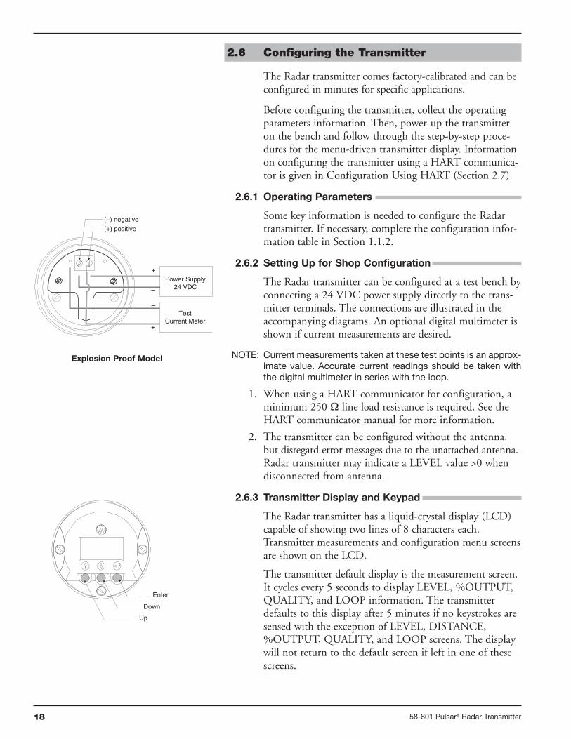
2.6.2 Setting Up for Shop Configuration
The Radar transmitter can be configured at a test bench byconnecting a 24 VDC power supply directly to the trans-mitter terminals. The connections are illustrated in theaccompanying diagrams. An optional digital multimeter isshown if current measurements are desired.
NOTE: Current measurements taken at these test points is an approx-imate value. Accurate current readings should be taken withthe digital multimeter in series with the loop.
1. When using a HART communicator for configuration, aminimum 250 Ω line load resistance is required. See theHART communicator manual for more information.
2. The transmitter can be configured without the antenna,but disregard error messages due to the unattached antenna.Radar transmitter may indicate a LEVEL value >0 whendisconnected from antenna.
2.6.3 Transmitter Display and Keypad
The Radar transmitter has a liquid-crystal display (LCD)capable of showing two lines of 8 characters each.Transmitter measurements and configuration menu screensare shown on the LCD.
The transmitter default display is the measurement screen.It cycles every 5 seconds to display LEVEL, %OUTPUT,QUALITY, and LOOP information. The transmitterdefaults to this display after 5 minutes if no keystrokes aresensed with the exception of LEVEL, DISTANCE,%OUTPUT, QUALITY, and LOOP screens. The displaywill not return to the default screen if left in one of thesescreens.
EnterDown
Up
+
–Power Supply
24 VDC
–
+
(–) negative(+) positive
TestCurrent Meter
Explosion Proof Model

1958-601 Pulsar® Radar Transmitter
Function in Function inArrows Display Mode Configuration Mode
Up and Down Moves forward and backward Increases or decreases thein the configuration program value displayed or moves tofrom one display to another. another choice.
Note: Hold arrow key forrapid scrolling.
Enter Enters the configuration mode Accepts a value and moves(noted by an exclamation point to the next step of theas the last character in the top configuration program.display line).
2.6.4 Password Protection (Default = 0)
The Radar transmitter is password protected to restrictaccess to certain portions of the menu structure that affectthe operation of the system. When the proper password isentered, an exclamation point (!) appears as the last char-acter of the first line of the display. The password can bechanged to any numerical value up to 255. The passwordis required whenever configuration values are changed.
The default password installed in the transmitter at thefactory is 0 (password disabled). The last step in the con-figuration menu provides the option to enter a new pass-word. If 0 is entered as a password, the transmitter is nolonger password protected and any value in the menu canbe altered (except diagnostic values) without entering aconfirming password.
NOTE: If the password is not known, the menu item New Passworddisplays an encrypted value representing the present pass-word. Call the factory with this encrypted value to determinethe actual password.
The keypad has three arrows used to scroll through thedisplays and to calibrate the transmitter – the Up andDown Arrow ( ) keys and the Enter ( ) key.

20 58-601 Pulsar® Radar Transmitter
2.6.5 Menu: Step-By-Step Procedure
The following table provides a complete explanation of thesoftware menus displayed by the Radar transmitter. Use thistable as a step-by-step guide to configure the transmitter.
The first column presents the menus shown on the trans-mitter display. The displays are in the order they wouldappear if the arrow keys were used to scroll through themenu. The numbers are not shown on the display. Theyare provided as a reference.
The second column provides the actions to take whenconfiguring the transmitter. Additional information or anexplanation of an action is given in the third column.
The following drawings are provided as reference for theconfiguration procedure.
Use of the included PACTware™ PC program is highlyrecommended and invaluable for troubleshooting andadvanced calibration. A HART RS232 or USB modem(purchased separately) is required. See MAGNETROLPACTware™ bulletin 59-101.
TankHeight
Sensor Offset + Tank Height =Distance from processconnection to tank bottom
20 mA
4 mA
Sensor Reference PointSensor Offset (+)
BlockingDistance
Distance
Safety Zone
MediaLevel
Level Offset
LowestMeasurable
Value
SensorReference
Point
SensorReference
Point
SensorReference
Point
NPT ProcessConnection
BSP ProcessConnection
ANSI or DIN Flange (Welded)
2158-601 Pulsar® Radar Transmitter
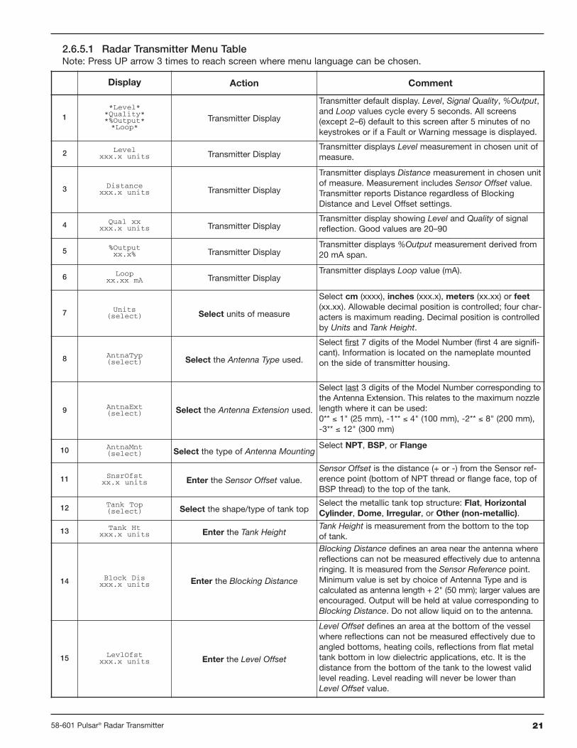
2.6.5.1 Radar Transmitter Menu TableNote: Press UP arrow 3 times to reach screen where menu language can be chosen.
Display Action Comment
1*Level*
*Quality**%Output**Loop*
Transmitter Display
Transmitter default display. Level, Signal Quality, %Output,and Loop values cycle every 5 seconds. All screens(except 2–6) default to this screen after 5 minutes of nokeystrokes or if a Fault or Warning message is displayed.
2 Levelxxx.x units Transmitter Display
Transmitter displays Level measurement in chosen unit ofmeasure.
3 Distancexxx.x units Transmitter Display
Transmitter displays Distance measurement in chosen unitof measure. Measurement includes Sensor Offset value.Transmitter reports Distance regardless of BlockingDistance and Level Offset settings.
4 Qual xxxxx.x units Transmitter Display
Transmitter display showing Level and Quality of signalreflection. Good values are 20–90
5 %Outputxx.x% Transmitter Display
Transmitter displays %Output measurement derived from20 mA span.
6 Loopxx.xx mA Transmitter Display
Transmitter displays Loop value (mA).
7 Units(select) Select units of measure
Select cm (xxxx), inches (xxx.x), meters (xx.xx) or feet(xx.xx). Allowable decimal position is controlled; four char-acters is maximum reading. Decimal position is controlledby Units and Tank Height.
8 AntnaTyp(select) Select the Antenna Type used.
Select first 7 digits of the Model Number (first 4 are signifi-cant). Information is located on the nameplate mountedon the side of transmitter housing.
9 AntnaExt(select) Select the Antenna Extension used.
Select last 3 digits of the Model Number corresponding tothe Antenna Extension. This relates to the maximum nozzlelength where it can be used:0** ≤ 1" (25 mm), -1** ≤ 4" (100 mm), -2** ≤ 8" (200 mm),-3** ≤ 12" (300 mm)
10 AntnaMnt(select) Select the type of Antenna Mounting
Select NPT, BSP, or Flange
11 SnsrOfstxx.x units Enter the Sensor Offset value.
Sensor Offset is the distance (+ or -) from the Sensor ref-erence point (bottom of NPT thread or flange face, top ofBSP thread) to the top of the tank.
12 Tank Top(select) Select the shape/type of tank top
Select the metallic tank top structure: Flat, HorizontalCylinder, Dome, Irregular, or Other (non-metallic).
13 Tank Htxxx.x units Enter the Tank Height
Tank Height is measurement from the bottom to the topof tank.
14 Block Disxxx.x units Enter the Blocking Distance
Blocking Distance defines an area near the antenna wherereflections can not be measured effectively due to antennaringing. It is measured from the Sensor Reference point.Minimum value is set by choice of Antenna Type and iscalculated as antenna length + 2" (50 mm); larger values areencouraged. Output will be held at value corresponding toBlocking Distance. Do not allow liquid on to the antenna.
15 LevlOfstxxx.x units Enter the Level Offset
Level Offset defines an area at the bottom of the vesselwhere reflections can not be measured effectively due toangled bottoms, heating coils, reflections from flat metaltank bottom in low dielectric applications, etc. It is thedistance from the bottom of the tank to the lowest validlevel reading. Level reading will never be lower thanLevel Offset value.
22 58-601 Pulsar® Radar Transmitter
Display Action Comment
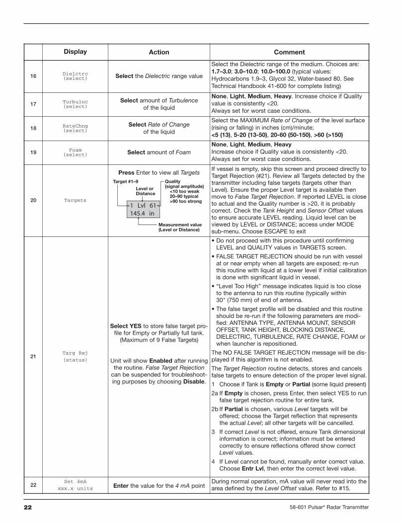
16 Dielctrc(select) Select the Dielectric range value
Select the Dielectric range of the medium. Choices are:1.7–3.0; 3.0–10.0; 10.0–100.0 (typical values:Hydrocarbons 1.9–3, Glycol 32, Water-based 80. SeeTechnical Handbook 41-600 for complete listing)
17 Turbulnc(select)
Select amount of Turbulenceof the liquid
None, Light, Medium, Heavy. Increase choice if Qualityvalue is consistently <20.Always set for worst case conditions.
18 RateChng(select)
Select Rate of Changeof the liquid
Select the MAXIMUM Rate of Change of the level surface(rising or falling) in inches (cm)/minute;<5 (13), 5-20 (13-50), 20-60 (50-150), >60 (>150)
19 Foam(select) Select amount of Foam
None, Light, Medium, HeavyIncrease choice if Quality value is consistently <20.Always set for worst case conditions.
20 Targets
Press Enter to view all TargetsIf vessel is empty, skip this screen and proceed directly toTarget Rejection (#21). Review all Targets detected by thetransmitter including false targets (targets other thanLevel). Ensure the proper Level target is available thenmove to False Target Rejection. If reported LEVEL is closeto actual and the Quality number is >20, it is probablycorrect. Check the Tank Height and Sensor Offset valuesto ensure accurate LEVEL reading. Liquid level can beviewed by LEVEL or DISTANCE; access under MODEsub-menu. Choose ESCAPE to exit
21Targ Rej(status)
Select YES to store false target pro-file for Empty or Partially full tank.(Maximum of 9 False Targets)
Unit will show Enabled after runningthe routine. False Target Rejectioncan be suspended for troubleshoot-ing purposes by choosing Disable.
• Do not proceed with this procedure until confirmingLEVEL and QUALITY values in TARGETS screen.
• FALSE TARGET REJECTION should be run with vesselat or near empty when all targets are exposed; re-runthis routine with liquid at a lower level if initial calibrationis done with significant liquid in vessel.
• “Level Too High” message indicates liquid is too closeto the antenna to run this routine (typically within30" (750 mm) of end of antenna.
• The false target profile will be disabled and this routineshould be re-run if the following parameters are modi-fied: ANTENNA TYPE, ANTENNA MOUNT, SENSOROFFSET, TANK HEIGHT, BLOCKING DISTANCE,DIELECTRIC, TURBULENCE, RATE CHANGE, FOAM orwhen launcher is repositioned.
The NO FALSE TARGET REJECTION message will be dis-played if this algorithm is not enabled.
The Target Rejection routine detects, stores and cancelsfalse targets to ensure detection of the proper level signal.
1 Choose if Tank is Empty or Partial (some liquid present)
2a If Empty is chosen, press Enter, then select YES to runfalse target rejection routine for entire tank.
2b If Partial is chosen, various Level targets will beoffered; choose the Target reflection that representsthe actual Level; all other targets will be cancelled.
3 If correct Level is not offered, ensure Tank dimensionalinformation is correct; information must be enteredcorrectly to ensure reflections offered show correctLevel values.
4 If Level cannot be found, manually enter correct value.Choose Entr Lvl, then enter the correct level value.
22Set 4mA
xxx.x units Enter the value for the 4 mA pointDuring normal operation, mA value will never read into thearea defined by the Level Offset value. Refer to #15.
Level orDistance
Measurement value(Level or Distance)
Quality(signal amplitude)
<10 too weak20–90 typical>90 too strong
Target #1–9

2358-601 Pulsar® Radar Transmitter
Display Action Comment
23Set 20mA
xxx.x unitsEnter the value for the 20 mA point
During normal operation, mA value will never read into thearea defined by the Blocking Distance value. Refer to #14.
24Damping
xxEnter the Damping factor
A damping factor (0–45) may be added to smooth a noisydisplay and/or output due to turbulence.
25SysFault(select)
Select the system Fault valueSelect 3.6 mA, 22 mA or HOLD (last value). See Section3.3.2 for Fault information.
26LOEFault(select)
Select the Loss of Echo Fault valueSelect 3.6 mA, 22 mA or HOLD (last value).
27LOEDelay(xxx sec)
Enter value for Loss of Echo DelaySelect a value 0–255; 30 is default
28SZ Fault(select)
Select the Safety Zone Fault
Safety Zone is a user-defined area just below the BlockingDistance. See drawing on page 20. Enable Fault if neces-sary to ensure safe, reliable high-level readings in criticalapplications. Choices are None, 3.6 mA, 22 mA, Latch3.6 or Latch 22. If Latch 3.6 or Latch 22 is chosen, theloop current will remain in alarm until it is manuallycleared with the SZ Alarm Reset below (#30)
29SZHeight
(xx.x units)Enter a Safety Zone Height
Enter a distance value that develops a safety zone justbelow the Blocking Distance. Here the unit will report aSafety Zone Fault (#28) if the level rises into this area.
30SZ AlarmReset
Reset Safety Zone LatchClear a latched Safety Zone alarm.
31Poll Adr
(xx)Enter HART Poll Address number
Enter a HART Poll Address (0–15). Enter 0 for a singletransmitter installation; enter 1–15 for multi-drop network(loop will latch at 4 mA).
32 Trim 4 Fine tune the 4 mA pointAttach a mA meter to the output. If the output does notequal 4.00 mA, adjust the value on the display until meterreads 4.00 mA.
33 Trim 20 Fine tune the 20 mA pointAttach a mA meter to the output. If the output does notequal 20.00 mA, adjust the value on the display untilmeter reads 20.00 mA.
34Trim Lvl
xxx.x unitsFine Tune the Level value
Trim Lvl is an offset value (± 10" or 244mm) to be usedto force the transmitter to output the exact Level. Thisshould only be used after all parameters have beenentered correctly, Tank Height and Sensor Offset havebeen confirmed accurate and it has been confirmed thatthe transmitter is tracking the correct level target.
35PIPE ID
xx.x unitsEnter Pipe ID
For mounting in a standpipe/stillwell. Enter a value forinside diameter of the pipe. Range of values is 0", 3" to20" (0, 40 to 500 mm). Value MUST be left as 0 if nostandpipe/stillwell is present.
36Loop Tstxx.xx mA
Enter a mA Output valueEnter a mA Output of any given value to perform loop test.
37New Pass
xxxEnter new Password
Use arrows to select desired value between 0 and 255;0=No Password. During normal operation, an encryptedpassword is shown.
38 Status Review Status informationStatus information is updated continuously showing onlythe most recent diagnostic events. See Diagnostic screenin Factory Menu for a cumulative review.
39 Language Select LanguageSelect the Language that will be displayed on the trans-mitter screen. Choices are English (default), Spanish,German and French.
40ModelRX5Verxx.xx
Revision informationProcessor firmware Rev level
Coprocessor firmware Rev level

24 58-601 Pulsar® Radar Transmitter
Display Action Comment
41 Disp Fact Review Factory parameters Select YES to reveal Factory parameters; NO to hide
42 Diagnost Review Diagnostic messages A cumulative review of all diagnostic messagesPress ENTER twice to clear
43 TrgRjLvl Review Target Rejection Level Shows level where the last Target Rejection routine was run
44 Launcher None, do not adjust Diagnostic, factory setting
45 Fact Cal None, do not adjust Diagnostic, factory setting
46 Peaks None, do not adjust Diagnostic, factory setting
47 Algorithm None, do not adjust Diagnostic, factory setting
48 Range None, do not adjust Diagnostic, factory setting
49 TVG Type None, do not adjust Diagnostic, factory setting
50 TVG Max None, do not adjust Diagnostic, factory setting
51 Fid Pos None, do not adjust Diagnostic, factory setting
52 Fid Gain None, do not adjust Diagnostic, factory setting
53 Sys Gain None, do not adjust Diagnostic, factory setting
54 Conversion Factor None, do not adjust Diagnostic, factory setting
55 Cef dm/s None, do not adjust Diagnostic, factory setting
56 Scale Offset None, do not adjust Diagnostic, factory setting
57 Distance Correction None, do not adjust Diagnostic, factory setting
58 Echo Amp None, do not adjust Diagnostic, factory setting
59 #Run Average None, do not adjust Diagnostic, factory setting
60 Adaptive Filter None, do not adjust Diagnostic, factory setting
61 #Adap Average None, do not adjust Diagnostic, factory setting
62 Scatter High None, do not adjust Diagnostic, factory setting
63 Rate High None, do not adjust Diagnostic, factory setting
64 Scatter Rate None, do not adjust Diagnostic, factory setting
65 Peak Detect Reference None, do not adjust Diagnostic, factory setting
66 Peak Detect Threshold None, do not adjust Diagnostic, factory setting
67 Minimum Threshold None, do not adjust Diagnostic, factory setting
68 ROC/min None, do not adjust Diagnostic, factory setting
69 Max Rate None, do not adjust Diagnostic, factory setting
70 Max dD None, do not adjust Diagnostic, factory setting
71 SZ Hysteresis None, do not adjust Diagnostic, factory setting
72 ES Delay None, do not adjust Diagnostic, factory setting
73 DataLog None, do not adjust Diagnostic, factory setting
Notes:
Clear all Diagnostic messages upon completion of configuration. See Screen 42 above.
It is encouraged that all setup information be recorded for future use. Table on page 45 is offered for this information.

2558-601 Pulsar® Radar Transmitter
2.7 Configuration Using HART®
A HART® (Highway Addressable Remote Transducer)remote unit, such as a HART communicator, can be used toprovide a communication link to the PULSAR transmitter.When connected to the control loop, the same system meas-urement readings shown on the transmitter are shown onthe communicator. In addition, the communicator can beused to configure the transmitter.
To confirm HART hand-held communications, attach unitper Section 2.7.1. If communicator reads GENERIC on firsttwo lines, the HART hand-held does not contain the currentDDs (device description) for the PULSAR Radar transmitter.Contact your local HART Service Center and specify aMAGNETROL PULSAR Model RX5 device descriptor.
See HART Revision Table, Section 2.7.3.
2.7.1 Connections
A HART communicator can be operated from a remotelocation by connecting it to a remote junction or by con-necting it directly to the terminal block in the electronicshousing of the PULSAR transmitter.
HART uses the Bell 202 frequency shift key technique ofhigh-frequency digital signals. It operates on the 4–20 mAloop and requires 250 Ω load resistance. A typical connec-tion between a communicator and the PULSAR transmitteris illustrated.
2.7.2 Display Menu
A typical communicator display is an 8-line by 21-characterLCD. When connected, the top line of each menu displaysthe model (Model RX5) and its tag number or address.Usually the bottom line of each menu is reserved for soft-ware-defined function keys (F1–F4). For detailed operatinginformation, refer to the instruction manual provided withthe HART communicator.
The PULSAR transmitter online menu trees are shown inthe following illustration. Open the menu by pressing thealphanumeric key 1, Device Setup, to display the second-level menu.
+-
Junction
RL > 250 Ω
ControlRoom
Display
PowerSupply
CurrentMeter
HART Version HCF Release Date Compatible with RX5 Software
Dev V2 DD V1 June 2003 Version 1.1a–1.2e
Dev V4 DD V1 June 2004 Version 2.0a and later
2.7.3 HART Revision Table
2.7.3.1 Model RX5

26 58-601 Pulsar® Radar Transmitter
2.7.4 HART Menu
11 Device ID12 Poll Address
1 Model2 Manufacturer3 Magnetrol, S/N4 Firmware Version5 Coprocessor Version6 Tag7 Descriptor8 Date9 Message
10 Final Asmbly Num
1 Tag2 Descriptor3 Date4 Message5 Poll addr6 Final Asmbly Num
1 Trim Loop Current2 Enter Password3 Factory Settings4 Magnetrol S/N5 New User Password6 Device ID
1 Loop Test2 Echo Amplitude3 Peaks4 Status5 Diagnostic Info6 Targ Rej Level7 Scatter8 Rate9 ROC per minute
1 Device Setup2 Level3 Quality
5 Loop6 Distance
4 % Output
1 Units2 Antenna Type3 Antenna Extension
5 Sensor Offset6 Tank Top7 Tank Height8 Blocking Distance9 Level Offset
10 Dielectric11 Turbulence12 Rate of Change13 Foam14 Targets15 Target Rejection16 4 mA Set Point17 20 mA Set Point18 Damping19 System Fault State20 LOE Fault State21 LOE Delay22 SZ Fault State23 SZ Height24 SZ Alarm Reset25 Trim Level26 Pipe ID27 Date/Time/Initials
4 Antenna Mount
13 Units14 Antenna Type15 Antenna Extension
17 Sensor Offset18 Tank Top19 Tank Height20 Blocking Distance21 Level Offset
23 Turbulence22 Dielectric
24 Rate of Change25 Foam26 Target Rej Status27 Target Rej Type28 Targ Rej Level29 4 mA Set Point30 20 mA Set Point31 Damping32 System Fault State33 LOE Fault State34 LOE Delay35 SZ Fault State36 SZ Height37 Trim Level38 Pipe ID39 Date/Time/Initials40 Launcher
16 Antenna Mount
1 Launcher2 Algorithm
4 TVG Type5 TVG Max6 Fiducial Position7 Fiducial Gain8 System Gain9 Conversion Factor
10 CF #Run Average11 Ceff12 Scale Offset13 Distance Corr
28 FactPar214 #Run Average
20 Peak Detect Thresh21 Min Threshold
23 Max Delta Distance24 SZ Hysteresis25 ES Delay26 DataLog
22 Max Rate
27 FactPar1
16 #Adaptive Average15 Adaptive Filter
17 Scatter High Limit18 Rate High Limit19 Peak Detect Ref
3 Range
1 Calibration
2 Basic Setup
3 Advanced Setup
4 Diagnostics
5 Review
41 Algorithm42 TVG Type
61 SZ Hysteresis62 ES Delay63 DataLog
44 Fiducial Position45 Fiducial Gain46 System Gain
47 Conversion Factor48 CF #Run Average49 Ceff50 Scale Offset51 #Run Average52 Adaptive Filter53 #Adaptive Average
55 Rate High Limit54 Scatter High Limit
56 Peak Detect Ref57 Peak Detect Thresh58 Min Threshhold
60 Max Delta Distance
43 TVG Max
59 Max Rate
64 4 mA Trim Value65 20 mA Trim Value66 Universal Rev67 Fld Dev Rev68 Software Rev69 Num Req Preams
2758-601 Pulsar® Radar Transmitter
3.0 Reference Information
This section presents an overview of the operation of thePULSAR Radar Level Transmitter, information on trou-bleshooting, common problems, listings of agencyapprovals, lists of replacement and recommended spareparts, and detailed physical, functional and performancespecifications.
3.1 Description
PULSAR is a two-wire, 24 VDC, level transmitter based onthe concept of pulse burst radar. The electronics are housedin an ergonomic housing comprised of two tandem com-partments angled at a 45 degree angle for ease of wiring andcalibration. These two compartments connect via an explo-sion-proof and watertight feed-through.
3.2 Theory of Operation
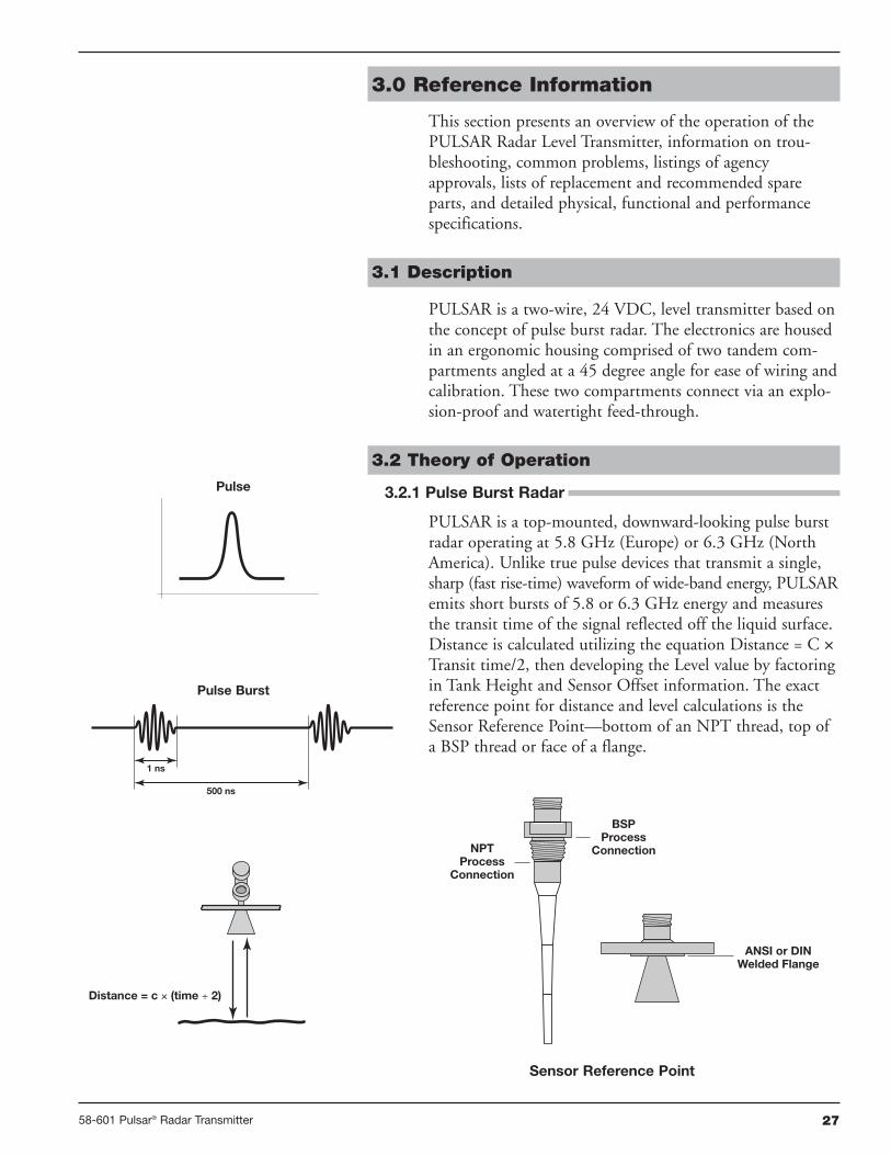
3.2.1 Pulse Burst Radar
PULSAR is a top-mounted, downward-looking pulse burstradar operating at 5.8 GHz (Europe) or 6.3 GHz (NorthAmerica). Unlike true pulse devices that transmit a single,sharp (fast rise-time) waveform of wide-band energy, PULSARemits short bursts of 5.8 or 6.3 GHz energy and measuresthe transit time of the signal reflected off the liquid surface.Distance is calculated utilizing the equation Distance = C ×Transit time/2, then developing the Level value by factoringin Tank Height and Sensor Offset information. The exactreference point for distance and level calculations is theSensor Reference Point—bottom of an NPT thread, top ofa BSP thread or face of a flange.
Distance = c × (time ÷ 2)
1 ns
500 ns
NPTProcess
Connection
BSPProcess
Connection
ANSI or DIN Welded Flange
Sensor Reference Point
Pulse
Pulse Burst

28 58-601 Pulsar® Radar Transmitter
The exact level measurement is extracted from false targetreflections and other background noise via the use ofsophisticated signal processing. The new PULSAR circuitryis extremely energy efficient so no duty cycling is necessary toaccomplish effective measurement. For this reason, PULSARcan track high rates of change that were heretofore impossiblewith existing loop-powered radar transmitters.
3.2.2 Equivalent Time Sampling
ETS, or Equivalent Time Sampling, is used to measure thehigh speed, low power EM (electromagnetic) energy. ETS isa critical key in the application of Radar to vessel levelmeasurement technology. The high speed electromagneticenergy (1000 ft/µs) is difficult to measure over short dis-tances and at the resolution required in the process industry.ETS captures the EM signals in real time (nanoseconds) andreconstructs them in equivalent time (milliseconds), whichis much easier to measure with today’s technology.
ETS is accomplished by scanning the tank to collect thou-sands of samples. The round-trip event on a 65 foot (20m)tank takes only 133 nanoseconds in real time. After it isreconstructed in equivalent time it measures 200 milliseconds.
TankHeight
Sensor Offset + Tank Height =Distance from processconnection to tank bottom
20
4 mA
Sensor Reference PointSensor Offset (+)
BlockingDistance
Distance
Safety Zone
MediaLevel
Level Offset
LowestMeasurable
Value
2958-601 Pulsar® Radar Transmitter
3.3 Troubleshooting
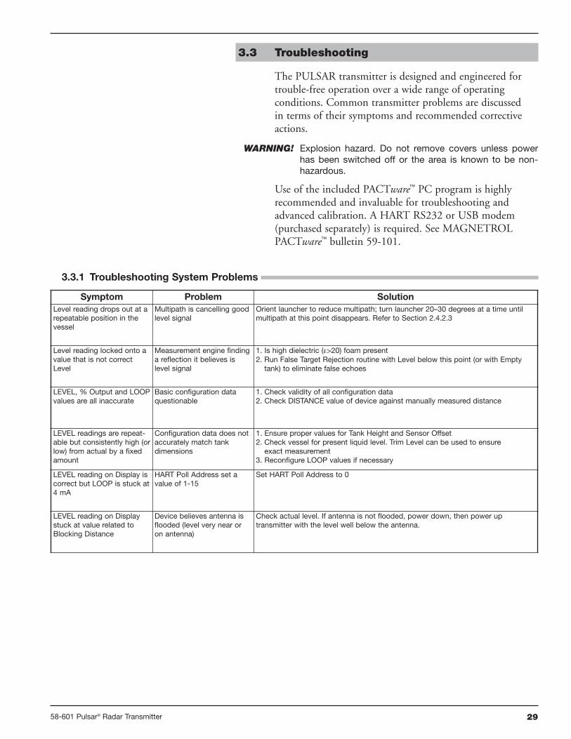
The PULSAR transmitter is designed and engineered fortrouble-free operation over a wide range of operatingconditions. Common transmitter problems are discussedin terms of their symptoms and recommended correctiveactions.
WARNING! Explosion hazard. Do not remove covers unless powerhas been switched off or the area is known to be non-hazardous.
Use of the included PACTware™ PC program is highlyrecommended and invaluable for troubleshooting andadvanced calibration. A HART RS232 or USB modem(purchased separately) is required. See MAGNETROLPACTware™ bulletin 59-101.
Symptom Problem SolutionLevel reading drops out at arepeatable position in thevessel
Multipath is cancelling goodlevel signal
Orient launcher to reduce multipath; turn launcher 20–30 degrees at a time untilmultipath at this point disappears. Refer to Section 2.4.2.3
Level reading locked onto avalue that is not correctLevel
Measurement engine findinga reflection it believes islevel signal
1. Is high dielectric (ε>20) foam present2. Run False Target Rejection routine with Level below this point (or with Emptytank) to eliminate false echoes
LEVEL, % Output and LOOPvalues are all inaccurate
Basic configuration dataquestionable
1. Check validity of all configuration data2. Check DISTANCE value of device against manually measured distance
LEVEL readings are repeat-able but consistently high (orlow) from actual by a fixedamount
Configuration data does notaccurately match tankdimensions
1. Ensure proper values for Tank Height and Sensor Offset2. Check vessel for present liquid level. Trim Level can be used to ensureexact measurement
3. Reconfigure LOOP values if necessary
LEVEL reading on Display iscorrect but LOOP is stuck at4 mA
HART Poll Address set avalue of 1-15
Set HART Poll Address to 0
LEVEL reading on Displaystuck at value related toBlocking Distance
Device believes antenna isflooded (level very near oron antenna)
Check actual level. If antenna is not flooded, power down, then power uptransmitter with the level well below the antenna.
3.3.1 Troubleshooting System Problems

30 58-601 Pulsar® Radar Transmitter
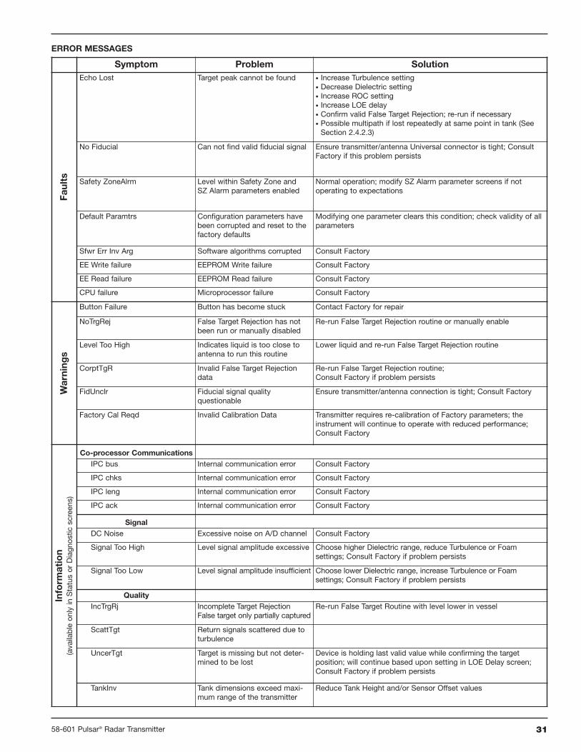
3.3.2 Error Messages
The PULSAR Radar transmitter utilizes a 3-section hierarchyfor reporting diagnostic conditions: FAULTS, WARNINGS,and INFORMATION. This information can be reviewed atthe STATUS screen in the user menu. This screen capturesonly current conditions. Historical information can beviewed at the DIAGNOSTIC screen in the Factory menu.
FAULT: The highest level in the hierarchy of diagnosticsannunciating a defect or failure in circuitry or software thatprecludes reliable measurement. The current (mA) valueunit defaults to 3.6, 22, or HOLD and a message is dis-played on the rotating screen. Further error information canbe obtained by viewing the Status or Diagnostic (FactoryMenu) screens.
WARNING (MESSAGE): The second level in the hierarchyof Diagnostics annunciating conditions that are not fatalbut may affect measurement. A message will occur on themain (rotating) screen when a Warning is detected but willnot affect output current. Further error information can beobtained by viewing the Status or Diagnostic screens.
INFORMATION (MESSAGE): The lowest level in thehierarchy of diagnostic conditions providing operationalfactors that are not critical to measurement. Further errorinformation can be obtained by viewing the Status orDiagnostic (Factory Menu) screens.
mA Loop Display Message Diagnostic (history)
Fault 3.6/22/HOLD Yes Yes
Warning No Effect Yes Yes
Information No Effect No Yes
EFFECTS OF EACH DIAGNOSTIC MESSAGE
3158-601 Pulsar® Radar Transmitter
Symptom Problem SolutionFa
ults
Echo Lost Target peak cannot be found • Increase Turbulence setting• Decrease Dielectric setting• Increase ROC setting• Increase LOE delay• Confirm valid False Target Rejection; re-run if necessary• Possible multipath if lost repeatedly at same point in tank (SeeSection 2.4.2.3)
No Fiducial Can not find valid fiducial signal Ensure transmitter/antenna Universal connector is tight; ConsultFactory if this problem persists
Safety ZoneAlrm Level within Safety Zone andSZ Alarm parameters enabled
Normal operation; modify SZ Alarm parameter screens if notoperating to expectations
Default Paramtrs Configuration parameters havebeen corrupted and reset to thefactory defaults
Modifying one parameter clears this condition; check validity of allparameters
Sfwr Err Inv Arg Software algorithms corrupted Consult Factory
EE Write failure EEPROM Write failure Consult Factory
EE Read failure EEPROM Read failure Consult Factory
CPU failure Microprocessor failure Consult Factory
Warning
s
Button Failure Button has become stuck Contact Factory for repair
NoTrgRej False Target Rejection has notbeen run or manually disabled
Re-run False Target Rejection routine or manually enable
Level Too High Indicates liquid is too close toantenna to run this routine
Lower liquid and re-run False Target Rejection routine
CorptTgR Invalid False Target Rejectiondata
Re-run False Target Rejection routine;Consult Factory if problem persists
FidUnclr Fiducial signal qualityquestionable
Ensure transmitter/antenna connection is tight; Consult Factory
Factory Cal Reqd Invalid Calibration Data Transmitter requires re-calibration of Factory parameters; theinstrument will continue to operate with reduced performance;Consult Factory
Inform
ation
(availableonlyinStatusor
Diagnostic
screens)
Co-processor CommunicationsIPC bus Internal communication error Consult Factory
IPC chks Internal communication error Consult Factory
IPC leng Internal communication error Consult Factory
IPC ack Internal communication error Consult Factory
SignalDC Noise Excessive noise on A/D channel Consult Factory
Signal Too High Level signal amplitude excessive Choose higher Dielectric range, reduce Turbulence or Foamsettings; Consult Factory if problem persists
Signal Too Low Level signal amplitude insufficient Choose lower Dielectric range, increase Turbulence or Foamsettings; Consult Factory if problem persists
QualityIncTrgRj Incomplete Target Rejection
False target only partially capturedRe-run False Target Routine with level lower in vessel
ScattTgt Return signals scattered due toturbulence
UncerTgt Target is missing but not deter-mined to be lost
Device is holding last valid value while confirming the targetposition; will continue based upon setting in LOE Delay screen;Consult Factory if problem persists
TankInv Tank dimensions exceed maxi-mum range of the transmitter
Reduce Tank Height and/or Sensor Offset values
ERROR MESSAGES

32 58-601 Pulsar® Radar Transmitter
3.4 Agency Approvals
FM RX5-5X0A-1X0 Intrinsically Safe Class I, Div. 1; Groups A, B, C, & DClass II, Div. 1; Groups E, F, & GClass III, NEMA 4X, T4 @80°CEntity
RX5-5X0A-3X0 Explosion Proof Class I, Div. 1; Groups B, C & DClass II, Div. 1; Groups E, F, & GClass III, NEMA 4X, T5 @80°C
RX5-5X0A-XX0 Non-Incendive Class I, Div. 2; Groups A, B, C, & DClass II, Div. 2; Groups F & GClass III, NEMA 4X
CSA RX5-5X0A-1X0 Intrinsically Safe Class I, Div. 1; Groups A, B, C, & DClass II, Div. 1; Groups E, F & GClass III, Type 4X, T4 @80°CEntity
RX5-5X0A-3X0 Explosion Proof Class I, Div. 1; Groups B, C & DClass II, Div. 1; Groups E, F, & GClass III, Type 4X, T5 @80°C
RX5-5X0A-XX0 Non-Incendive Class I, Div. 2; Groups A, B, C, & DClass II, Div. 2; Groups E, F, & GClass III, Type 4X, T4 @80°C
ATEX R05-5X0A-AX0 Intrinsically Safe ATEX II 1G EEx ia IIC T4 @70°CIEC Ex ia IIC T4@70°C
R05-5X0A-CX0 Explosion Proof ATEX II 1/2G EEx d IIC T6 @70°C
AGENCY MODEL PROTECTION METHOD AREA CLASSIFICATION
These units have been tested to EN 61326: 1997+A1+A2and are in compliance with the EMC Directive 2004/108/EC.
COMMUNICATIONS APPROVALS
ATEX/IEC Entity Parameters
Region Agency Frequency
US FCC 6.3 GHz
Canada IC 6.3 GHz
Europe RTTE 5.8 GHz
Vi 28.4VDC
li 120mA
Pi 0.84w
Ci 2.2nF
Li 430µH
PULSAR Model RX5
SIL 1 as 1oo1
Instrument Type B
SFF 73.7%
PFDavg 9.72E-04
FITS Annual
Fail Dangerous Undetected 222 1.94E-03
Fail Dangerous Detected 308 2.70E-03
Safe 314 2.75E-03
Measured media inside vessel must be non-flammable only.
The antenna complies with Canadian Electrical Code requirementsof ANSI/ISA 12.27.01-2003 as a single seal device.
Special conditions for safe use:
Ex iaWhen an insulated probe is used in a potentially explosive atmospherecaused by gas, damp or a non-conducting liquid, precautions mustbe taken to avoid ignition due to hazardous electrostatic charges.
Ex dWhen the transmitter enclosure that is made of aluminum alloy isinstalled in a potentially explosive atmosphere, requiring the use ofapparatus of equipment category 1G, it shall be installed so that inthe event of rare incidents, an ignition source due to impact or frictionbetween the enclosure and iron/steel is excluded.
The transmitter’s antenna shall be installed so that electrostaticdischarges are prevented.
SIL

3358-601 Pulsar® Radar Transmitter
3.4.1 Agency (FM/CSA) Drawing and Entity Parameters
34 58-601 Pulsar® Radar Transmitter
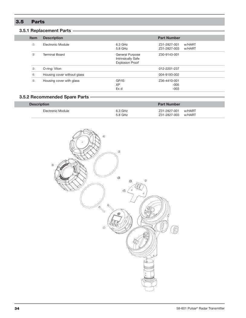
3.5 Parts
3.5.1 Replacement Parts
Item Description Part Number
Electronic Module 6.3 GHz Z31-2827-001 w/HART5.8 GHz Z31-2827-003 w/HART
Terminal Board General Purpose Z30-9143-001Intrinsically SafeExplosion Proof
O-ring: Viton 012-2201-237
Housing cover without glass 004-9193-002
Housing cover with glass GP/IS Z36-4410-001XP 036-4410-005Ex d 036-4410-003
3.5.2 Recommended Spare Parts
Description Part Number
Electronic Module 6.3 GHz Z31-2827-001 w/HART5.8 GHz Z31-2827-003 w/HART

3558-601 Pulsar® Radar Transmitter
System Design
Measurement Principle Pulse burst radar @ 5.8 GHz (Europe), 6.3 GHz (U.S.)
Input
Measured Variable Level, determined by the time-of-flight of a radar pulse from
transmitter to product surface and back
Span 0.5 to 65 feet (0.2 m to 20 m)
Output
Type Analog 4 to 20 mA with optional HART digital signal
Range Analog 3.8 to 20.5 mA useable
Digital 0 to 999" (0 to 9999 cm)
Resolution Analog 0.01 mA
Digital 0.1"
Loop Resistance GP/IS/XP - 400 Ω @ 24 VDC/20 mA, 350 Ω @ 24 VDC/22 mA
Diagnostic Alarm Adjustable 3.6 mA, 22 mA, HOLD
Damping Adjustable 0-45
User Interface
Keypad 3-button menu-driven data entry and system security
Indication 2-line × 8-character display
Digital Communication HART Version 5 compatible
Power (Measured at instrument terminals)
General Purpose 16 to 36 VDC
Intrinsically Safe 16 to 28.6 VDC
Explosion Proof 16 to 36 VDC
Housing
Material Cast aluminum A356T6 (<0.2% copper), cast 316 SS (optional)
Cable Entry 3⁄4" NPT, M20
Ingress Protection Type 4X (IP66)
Net/Gross Weight Aluminum 6 lbs (2.36 kg) / 7 lbs (2.76 kg)
316 Stainless steel 13.5 lbs (5.3 kg) / 14 lbs (5.7 kg)
Overall Dimensions H 10.21" (259 mm) × W 4.38" (111 mm) × D 7.40" (188 mm)
3.6 Specifications
3.6.1 Functional – Transmitter
Ω
VDC
1200
1000
28.6 V630 Ω
@ 20 mA
36 V1000 Ω
800
600
400
200
00 10 2016
350
30 40
General Purpose &Explosion Proof
Intrinsically Safe
(350 @ 22 mA)
24
RTTE: European approval, FCC & IC: North American approval
36 58-601 Pulsar® Radar Transmitter
Material CodeMaximum
TemperatureMaximumPressure
Min.Temp.
RecommendedFor Use In
Not RecommendedFor Use In
Viton® GFLT 0+400° F @ 232 psig(+200° C @ 16 bar)
750 psig @ +70° F(50 bar @ +20° C)
-40° F(-40° C)
General purpose, steam,ethylene
Ketones (MEK, acetone),skydrol fluids, amines, anhydrousammonia, low molecular weightesters and ethers, hot hydrofluoricor chlorosulfuric acids, sour HCs
EPDM 1+250° F @ 200 psig(+125° C @ 14 bar)
750 psig @ +70° F(50 bar @ +20° C)
-60° F(-50° C)
Acetone, MEK, skydrol fluidsanhydrous ammonia
Petroleum oils, di-ester baselubricants, propane, steam
Simriz SZ485(formerly
Aegis PF128)8
+400° F @ 232 psig+(200° C @ 16 bar)
750 psig @ +70° F(50 bar @ +20° C)
-4° F(-20° C)
Inorganic and organic acids(including HF and nitric),aldehydes, ethylene, glycols,organic oils, silicone oils,vinegar, sour HCs, steam,amines, ethylene oxide,propylene oxide
Black liquor, Freon 43, Freon 75,Galden, KEL-F liquid, moltensodium, molten potassium
Kalrez (4079) 2+400° F @ 232 psig+(200° C @ 16 bar)
750 psig @ +70° F(50 bar @ +20° C)
-40° F(-40° C)
Inorganic and organic acids(including HF and nitric),aldehydes, ethylene, glycols,organic oils, silicone oils,vinegar, sour HCs
Black liquor, hot water/steam, hotaliphatic amines, ethylene oxide,propylene oxide, molten sodium,molten potassium
Reference Conditions Reflection from ideal reflector at +70° F (+20° C)
Linearity ±0.4 inch (10 mm) or 0.1% of tank height (whichever is greater)
Measured Error ±0.4 inch (10 mm) or 0.1% of tank height (whichever is greater)(Performance will degrade slightly within 60" (1.5 m) of antenna)
Resolution 0.1 inch (2.5 mm)
Repeatability < 0.2 inch (5 mm) or 0.05% of tank height
Response Time < 1 second
Warm-up Time 30 seconds
Operating Temp. Range -40° to +175° F (-40° to +80° C) (ATEX EEx d: -40 to +160° F (-40 to +70° C))
LCD Temp. Range -5° to +160° F (-20° to +70° C)
Ambient Temp. Effect 0.05% per 10° C
Process Dielectric Effect < 0.3 inch within selected range
Maximum Rate of Change 180 inches (450 cm)/minute
3.6.2 Performance
Environment
Operating Temperature -40 to +175° F (-40 to +80° C)
LCD Operating Temperature Range -5 to +160° F (-20 to +70° C)
Storage Temperature -50 to +175° F (-46 to +80° C)
Humidity 0-99%, non-condensing
Electromagnetic Compatibility Meets CE Requirements: EN 50081-2, EN 50082-2
Surge Protection Meets CE Requirements: EN 61326 (1000 volts)
Shock Class ANSI/ISA-S71.03 Class SA1
Vibration Class ANSI/ISA-S71.03 Class VC2
3.6.3 O-ring (seal) Selection Chart
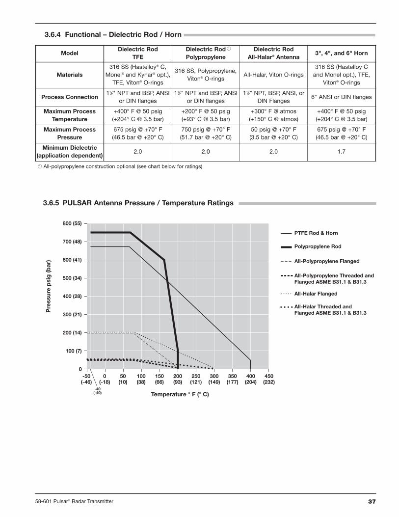
3758-601 Pulsar® Radar Transmitter
3.6.4 Functional – Dielectric Rod / Horn
3.6.5 PULSAR Antenna Pressure / Temperature Ratings
-50(-46)
-40(-40)
0(-18)
0
100 (7)
200 (14)
300 (21)
400 (28)
500 (34)
600 (41)
700 (48)
800 (55)
50(10)
100(38)
150(66)
200(93)
250(121)
300(149)
350(177)
400(204)
450(232)
Temperature ° F (° C)
Pre
ssur
ep
sig
(bar
)
Polypropylene Rod
PTFE Rod & Horn
All-Polypropylene Flanged
All-Polypropylene Threaded andFlanged ASME B31.1 & B31.3
All-Halar Threaded andFlanged ASME B31.1 & B31.3
All-Halar Flanged
ModelDielectric Rod
TFEDielectric RodPolypropylene
Dielectric RodAll-Halar® Antenna
3", 4", and 6" Horn
Materials316 SS (Hastelloy® C,
Monel® and Kynar® opt.),TFE, Viton® O-rings
316 SS, Polypropylene,Viton® O-rings
All-Halar, Viton O-rings316 SS (Hastelloy Cand Monel opt.), TFE,
Viton® O-rings
Process Connection11⁄2" NPT and BSP, ANSI
or DIN flanges11⁄2" NPT and BSP, ANSI
or DIN flanges11⁄2” NPT, BSP, ANSI, or
DIN Flanges6" ANSI or DIN flanges
Maximum ProcessTemperature
+400° F @ 50 psig(+204° C @ 3.5 bar)
+200° F @ 50 psig(+93° C @ 3.5 bar)
+300° F @ atmos(+150° C @ atmos)
+400° F @ 50 psig(+204° C @ 3.5 bar)
Maximum ProcessPressure
675 psig @ +70° F(46.5 bar @ +20° C)
750 psig @ +70° F(51.7 bar @ +20° C)
50 psig @ +70° F(3.5 bar @ +20° C)
675 psig @ +70° F(46.5 bar @ +20° C)
Minimum Dielectric(application dependent)
2.0 2.0 2.0 1.7
All-polypropylene construction optional (see chart below for ratings)
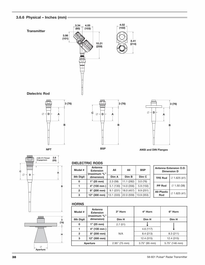
38 58-601 Pulsar® Radar Transmitter
3.6.6 Physical – Inches (mm)
ANSI and DIN Flanges
3 (76)
B
AD∅
NPT
3 (76)
B
AD∅
BSP
3 (76)
B
AC D∅
Dielectric Rod
Transmitter
10.21(259)
3.98(101)
3.34(85)
4.05(103)
8.41(214)
4.02(102)
Model #Antenna
Extension(maximum “L”
dimension)
All All BSP
8th Digit Dim A Dim B Dim C
0 1" (25 mm) 2.3 (58) 11.1 (282) 3.0 (76)
1 4" (100 mm ) 5.1 (130) 14.0 (356) 5.9 (150)
2 8" (200 mm) 9.1 (231) 18.0 (457) 9.9 (251)
3 12" (300 mm) 13.1 (333) 22.0 (559) 13.9 (353)
Antenna Extension O.D.Dimension D
TFE Rod ∅ 1.625 (41)
PP Rod ∅ 1.50 (38)
All-PlasticRod
∅ 1.625 (41)
DIELECTRIC RODS
HORNS
2.8(55)
0.68 (17) ThreadEngagement
AC
B
D∅
3(76)
H
∅Aperture
Model #Antenna
Extension(maximum “L”
dimension)
3" Horn 4" Horn 6" Horn
8th Digit Dim H Dim H Dim H
0 1" (25 mm) 2.7 (51)
1 4" (100 mm )
N/A
4.6 (117)
2 8" (200 mm) 8.4 (213) 8.3 (211)
3 12" (300 mm) 12.4 (315) 12.4 (315)
Aperture 2.95" (75 mm) 3.75" (95 mm) 5.75" (146 mm)

3958-601 Pulsar® Radar Transmitter
3.7 Model Numbers
3.7.1 PULSAR Radar Transmitter
1 4–20 mA with HART
R 5 5 1 0 A 0
R95 Through-Air Radar Level Transmitter- 6.3 GHz Pulse Radar (North America)R05 Through-Air Radar Level Transmitter- 5.8 GHz Pulse Radar (Europe)
BASIC MODEL NUMBER AND OPERATING FREQUENCY
SIGNAL OUTPUT
A Digital Display and KeypadACCESSORIES
5 24 VDC, Two-wirePOWER
1 Cast Aluminum, Dual Compartment, 45° / 3⁄4" NPT (IP66)2 Cast Aluminum, Dual Compartment, 45° / M20 (IP66)3 Cast 316 SS, Dual Compartment, 45° / 3⁄4" NPT (IP66)
4 Cast 316 SS, Dual Compartment, 45° / M20 (IP66)
HOUSING/CONDUIT CONNECTION
1Integral, General Purpose & Intrinsically Safe (FM & CSA),Non-incendive (CL1, Div II)
3Integral, Explosion-Proof(FM & CSA Class I Div. 1, Groups B, C & D)
AIntegral, General Purpose & Intrinsically Safe(ATEX II 1G EEx ia IIC T4IEC Ex ia IIC T4)
C Integral, Explosion-Proof (ATEX II 1/2G EEx d ia IIC T6)
MOUNTING/CLASSIFICATION
Measured media inside vessel must be non-flammable only.
Consult factory for delivery.

40 58-601 Pulsar® Radar Transmitter
3.7.2 Radar Antennas – Dielectric Rod
31 11⁄2" NPT thread 32 11⁄2" BSP (G 11⁄2) thread43 2" 150# ANSI raised face flange DA DN 50, PN 16 DIN 2527 Form B44 2" 300# ANSI raised face flange DB DN 50, PN 25/40 DIN 2527 Form B45 2" 600# ANSI raised face flange DD DN 50, PN 64 DIN 2527 Form E53 3" 150# ANSI raised face flange EA DN 80, PN 16 DIN 2527 Form B54 3" 300# ANSI raised face flange EB DN 80, PN 25/40 DIN 2527 Form B55 3" 600# ANSI raised face flange ED DN 80, PN 64 DIN 2527 Form E63 4" 150# ANSI raised face flange FA DN 100, PN 16 DIN 2527 Form B64 4" 300# ANSI raised face flange FB DN 100, PN 25/40 DIN 2527 Form B65 4" 600# ANSI raised face flange FD DN 100, PN 64 DIN 2527 Form E73 6" 150# ANSI raised face flange GA DN 150, PN 16 DIN 2527 Form B74 6" 300# ANSI raised face flange GB DN 150, PN 25/40 DIN 2527 Form B75 6" 600# ANSI raised face flange GD DN 150, PN 64 DIN 2527 Form E
R A 0 0
R A PULSAR radar antennas / 5.8/6.3 GHzTECHNOLOGY / OPERATING FREQUENCY
A TFE (Material of Construction codes A, B, C, and K only)B Polypropylene (Material of Construction codes A, G, K, and L only)C Halar® (Material of Construction codes G and L only)
CONFIGURATION / STYLE
A 316/316L stainless steelB Hastelloy® CC Monel®
G All-Plastic wetted surfaces including flanges (Configuration/Style codes B and C only)K 316/316L SS; ASME B31.1 and B31.3 (meets CRN specifications)
L All-Plastic wetted surfaces; ASME B31.1, B31.3(meets CRN specifications; Configuration/Style codes B and C only)
MATERIAL OF CONSTRUCTION
0 Viton® GFLT1 EPDM2 Kalrez 40798 Aegis PF128
O-RINGS
0 For nozzle height ≤ 1" (25 mm) (For threaded process connection only)1 For nozzle height ≤ 4" (100 mm)2 For nozzle height ≤ 8" (200 mm) (ESP designation for TFE rod only)3 For nozzle height ≤ 12" (300 mm)
ANTENNA EXTENSION
PROCESS CONNECTION - SIZE/TYPE
Metal flanges welded to antenna; Plastic flanges and metal flanges with threadedantenna connection ordered separately. Refer to Optional Flanges chart on page 41.
All-Polypropylene and All-Halar antennas (Materials of Construction Codes G and L)use Viton® GFLT O-rings
4P 2" Triclover® type, 16 AMP 6P 4" Triclover type, 16 AMP5P 3" Triclover type, 16 AMP 7P 6" Triclover type, 16 AMP
HYGIENIC PROCESS CONNECTIONS

4158-601 Pulsar® Radar Transmitter
3.7.3 Radar Antennas – Horn
R A PULSAR radar antennas / 5.8/6.3 GHzTECHNOLOGY / OPERATING FREQUENCY
3 3" horn (for Standpipe/Stillwell use only; Materials of Construction codes A & K only4 4" horn6 6" horn
CONFIGURATION / STYLE
A 316/316L stainless steelB Hastelloy CK 316/316L SS; ASME B31.1 and ASME B31.3 (meets CRN specifications)
MATERIAL OF CONSTRUCTION
0 Viton® GFLT1 EPDM2 Kalrez® 40798 Simriz SZ485 (formerly Aegis PF128)
O-RINGS
0 For 3" Horn in standpipes/stillwells only1 For nozzle height ≤ 4" (100 mm) - Configuration Style code 4 only2 For nozzle height ≤ 8" (200 mm)3 For nozzle height ≤ 12" (300 mm)
OPTIONAL FLANGES (for use with Antenna Extension Codes 1–3 only)
R A 0 0
ANTENNA EXTENSION
53 3" 150# ANSI raised face flange54 3" 300# ANSI raised face flange55 3" 600# ANSI raised face flange63 4" 150# ANSI raised face flange64 4" 300# ANSI raised face flange65 4" 600# ANSI raised face flange73 6" 150# ANSI raised face flange74 6" 300# ANSI raised face flange75 6" 600# ANSI raised face flangeFA DN 100, PN 16 DIN 2527 Form BFB DN 100, PN 25/40 DIN 2527 Form BFD DN 100, PN 64 DIN 2527 Form EGA DN 150, PN 16 DIN 2527 Form BGB DN 150, PN 25/40 DIN 2527 Form BGD DN 150, PN 64 DIN 2527 Form E
PROCESS CONNECTION - SIZE/TYPE
6P 4" Tri-Clover type, 16 AMP Hygienic Flange7P 6" Tri-Clover type, 16 AMP Hygienic Flange
HYGIENIC PROCESS CONNECTIONS
Part Number:04-6852
2"150# 300#
3"150# 300#
4"150# 300#
6"150# 300#
316L Stainless Steel -001 -005 -002 -006 -003 -007 -004 -008304L Stainless Steel -009 -013 -010 -014 -011 -015 -012 -016Carbon Steel -017 -021 -018 -022 -019 -023 -020 -024Hastelloy C -025 -029 -026 -030 -027 -031 -028 -032Monel -033 -037 -034 -038 -035 -039 -036 -040
Part Number:04-6852
2"150# 300#
3"150# 300#
4"150# 300#
6"150# 300#
Kynar -041 -045 -042 -046 -043 -047 -044 -048PVC -049 -053 -050 -054 -051 -055 -052 -056Polypropylene -057 -061 -058 -062 -059 -063 -060 -064TFE -065 -069 -066 -070 -067 -071 -068 -072

42 58-601 Pulsar® Radar Transmitter
Accuracy The closeness of agreement between the result ofmeasurement and the true value of the measure (inaccuracyequals the maximum positive and negative % deviation over thetotal span).
ANSI American National Standards Institute.
Antenna A mechanical component that serves as an impedancematch between the transmission of a signal in a cable (or wave-guide) and air.
AntnaMnt Antenna Mount The type of process mounting(NPT, BSP or Flange) utilized in the installation. This aids inestablishing an exact Sensor Reference Point for Radar propaga-tion and measurement.
AntnaTyp Antenna Type A particular antenna configuration ordesign. Each antenna design has a set of unique performancecharacteristics.
ATEX ATmosphere EXplosive European regulations governing theuse in hazardous areas.
BlockDist Blocking Distance The area near the antenna wherereflections cannot be measured effectively due to antenna ringingand noise.
CE Conformité Européene Standards and performance criteria forthe new European Union.
CENELEC Comité Européen de Normalisation ElectrotechniqueEuropean organization that sets standards for electrical equipment.
CSA Canadian Standards Association Canadian, third partyagency that qualifies the safety of electrical equipment.
Damping Factor applied to smooth output variations due toturbulence.
Default Screen The main position of the menu structure thatdisplays the primary measurement values of LEVEL, Quality,% OUTPUT, and LOOP. The transmitter returns to thisposition after 5 minutes of inactivity (except Screens 2-6).
Diagnostics Three levels of error messages; Fault, Warning andInformation.
Dielectric Constant (ε) The electrical permittivity of a material.The units are farad/meter. Typical values: Hydrocarbons 1.9–3,Glycol 32, Water-based media 80. See Technical Handbook41-600 for complete listing.
Dielectric Rod antenna A non-metallic (TFE and polypropylenetypical) transition between the microwave waveguide and air.
Distance The present reading measured from the transmitter’sSensor Reference Point to the material in a vessel; complimentof Level.
DVM/DMM Digital Volt Meter/Digital Multimeter.
Electromagnetic Energy The radiation that travels throughspace as electric and magnetic fields varying with position andtime. Examples in increasing frequency: radio waves, microwave,infrared light, visible light, ultraviolet light, x-rays, gammawaves, and cosmic waves.
EM See Electromagnetic Energy.
EMI Electromagnetic Interference Electrical noise caused by elec-tromagnetic fields that may affect electrical circuits, particularlylow-power electronic devices.
EN European Normal Committee guidelines in EC countriesthat take precedence over local, country guidelines.
ENV Preliminary EN guidelines, or pre-standards.
Ergonomic A mechanism that considers human capability in itsdesign or function.
ETS Equivalent Time Sampling Process that captures high speedelectromagnetic events in real time (nanoseconds) and recon-structs them into an equivalent time (milliseconds).
Explosion Proof Enclosure An enclosure designed to withstandan explosion of gas or vapor within it and prevent the explosionfrom spreading outside the enclosure.
Factory Sealed A third-party-approved Explosion Proof sealinstalled in the unit during manufacturing. This alleviates theend user from installing an external XP seal adjacent (within18") to the device.
Fault The highest level in the hierarchy of diagnostics annunci-ating a defect or failure in circuitry or software that preclude reli-able measurement. The current (mA) value unit defaults to 3.6,22, or Hold and a message is displayed on the rotating screen.Further information can be obtained by viewing the Status orDiagnostic (Factory Menu) screens.
Feedthrough A small, connecting cavity between the main hous-ing compartments, carrying the cable that supplies the operatingenergy to the measurement circuitry and returns the outputvalue proportional to level. This cavity is potted to maintain theenvironmental isolation between the two compartments.
Fiducial A reference signal (baseline) to which all measurementsare referenced.
FM Factory Mutual American, third party agency that qualifiesthe safety of electrical equipment.
Foam The entraining of air in a liquid. The effect of foam onradar measurement is based on four factors; 1.) dielectric of theliquid from which the foam has developed, 2.) density of thefoam (bubble size), 3.) amount of foam above the liquid and, toa lesser extent, 4.) wall thickness of the bubbles.
Glossary

4358-601 Pulsar® Radar Transmitter
Four Wire An electronic instrument design that uses one set ofwires to supply power (120/240 VAC, 24 VDC) and another setto carry the process measurement signal (4–20 mA). Also calledLine Powered.
FSK Frequency Shift Keying See HART.
Gain Amplification adjustment to attain optimum performancein various product dielectric ranges. (Factory setting).
Ground An electrical connection to the Earth’s potential that isused as a reference for the system and electrical safety.
Grounded A state where no electrical potential exists betweenthe ground (green) connection on the transmitter and the Earthor system ground.
Guided Wave Radar See TDR.
HART Highway Addressable Remote Transducer Protocol thatuses the Bell 202 frequency shift keying (FSK) method to super-impose low level frequencies (1200/2000 Hz) on top of the stan-dard 4–20 mA loop to provide digital communication.
HART ID See Poll Address.
Hazardous Area An area where flammable gases or vapors are ormay be present in the air in quantities sufficient to produceexplosive or ignitable mixtures.
Horn Antenna A metallic, cone transition between themicrowave waveguide and air.
IEC International Electrotechnical Commission Organization thatsets international standards for electrical devices.
Increased Safety Designs and procedures that minimize sparks,arcs, and excessive temperatures in hazardous areas. Defined bythe IEC as Zone 1 environments (Ex e).
Information (message) The lowest level in the hierarchy ofdiagnostic conditions providing operational factors that are notcritical to measurement. Further information can be obtained byviewing the Status or Diagnostic (Factory Menu) screens.
Intrinsically Safe Ground A very low resistance connecting to aground, in accordance with the National Electrical Code (NEC,ANSI/NFPA 70 for FMRC), the Canadian Electrical Code(CEC for CSA), or the local inspector.
Intrinsic Safety A design or installation approach that limits theamount of energy that enters a hazardous area to eliminate thepotential of creating an ignition source.
Level The present reading of the height of material in a vessel;compliment of Distance.
LevlOfst Level Offset The distance above the tank bottom whereradar level measurement is impossible due to heating coils, baf-fles, angled or curved tank bottoms, etc. The mA output willnever read lower than the Level Offset value.
Linearity The worst case error calculated as a deviation from aperfect straight line drawn between two calibration points.
Line Powered See Four Wire.
LOE Loss of Echo Condition where a level measurement isimpossible due to the absence of valid reflections from the liquidsurface.
LOE Delay Loss of Echo Delay The amount of time the trans-mitter spends looking for a valid Level signal before going intoLoss of Echo Fault The last valid Level reading is held duringthis search.
LOE Fault Loss of Echo Fault The mA value to which the outputis driven after the Loss of Echo Delay times out; choices are3.6mA, 22mA and HOLD.
Loop The present reading of the 4–20 mA current output.
Loop Powered See Two Wire.
Loop Tst Loop Test Built-in system capability to test/calibrate aloop (or separate loop device) by driving the transmitter outputto a particular value.
Low Voltage Directive A European Community requirement forelectrical safety and related issues of devices using 50-1000 VDCor 75–1500 VAC.
Measured Value The typical level measurement values used totrack the level of a process: Level, % Output, and Loop.
Media The liquid material being measured by the level trans-mitter.
Multidrop The ability to install, wire, or communicate withmultiple devices over one cable. Each device is given a uniqueaddress and ID.
Non-hazardous Area An area where no volatile mixtures ofvapors/gas and oxygen will be found at any time. Also calledGeneral Purpose Area.
Non-Incendive A circuit in which any arc or thermal effect pro-duced, under intended operating conditions of the equipment ordue to opening, shorting, or grounding of field wiring, is inca-pable, under specific test conditions, of igniting the flammablegas, vapor, or dust-air mixture.
Password A numerical value between 0 and 255 that protectsstored configuration data from unauthorized manipulation.
Percent (%) Output The present reading as a fraction of the16 mA scale (4–20 mA).
Poll Address (HART ID) A number between 1 and 15 whichsets an address or location of a device in a multi-drop loop. Polladdress for single device configuration is 0.
Qual Quality A relative value (0–99) that shows the strengthand usefulness for a given reflected signal.
QuickStart The essential information needed for the PULSARradar transmitter and antenna to be installed, wired, and calibrated.
Radar (Radio Detection And Ranging) Uses EM energy andhigh speed timing circuits to determine distance. Original Radardevices used energy in the radio frequency range (MHz), manycurrent devices use much higher frequencies (GHz).

44 58-601 Pulsar® Radar Transmitter
Range The distance over which the transmitter scans for validreturn signals.
RateChng Rate of Change The maximum velocity of verticalmovement of a liquid’s surface.
Relative Dielectric (εr) A unitless number that indicates therelative permittivity of a material.
Repeatability The maximum error between two or more outputreadings of the same process condition.
RFI Radio Frequency Interference Electrical noise that can havean adverse affect on electrical circuits, particularly low-powerdevices.
Safety Zone A user-defined area just below the BlockingDistance where level measurement still has a high degree of relia-bility. Radar can develop ambiguous readings when the levelreaches the region of the antenna. An alarm can be annunciatedin this area for critical applications where reliable measurement isa necessity for safety reasons.
Safety Zone Height The height of the region below theBlocking Distance where an alarm will be annunciated upondetection of liquid.
Safety Zone Fault An optional condition added, when necessary,to ensure safe, reliable high-level readings in critical applications.Choices are 3.6 mA, 22 mA, Latch 3.6 or Latch 22. If Latch 3.6or Latch 22 are chosen, the loop current will remain in alarmuntil it is cleared in SZ Latch menu screen.
Safety Zone Alarm Reset Use screen for clearing a LatchedAlarm set in Safety Zone Fault (above)
SnsrOfst Sensor Offset The distance (+ or -) between thecustomer’s 100% reference point (tank top) and the Sensorreference point (bottom of NPT thread, top of BSP threador face of flange).
Span The difference between the upper and lower limits of therange.
Specific Gravity (SG) The ratio of the density of a material tothe density of water at the same conditions.
Sensitivity The amount of amplification applied to the Levelsignal; a higher value aids in measuring low dielectric media; alower number assists in ignoring nearby objects.
Status The current state of the transmitter’s diagnostics; screenupdates every 10 seconds.
Targets Objects in the vessel that create reflections of the radarsignal (microwave energy).
Targ Rej Target Rejection The ability to ignore reflections fromobjects in the vessel that are not the liquid level, i.e., false targets(e.g. pipes, ladders, baffles).
Tank Ht Tank Height The tank measurement between the 0%(tank bottom) and 100% (tank top).
Tank Top The 100% point in a vessel. Also considered for thetype of tank top; e.g. flat, dome, etc., which affects the develop-ment of multiple echoes during high level conditions. Multipleechoes can appear as an invalid Level signal.
TDR (Time Domain Reflectometry) Uses a waveguide to carryEM energy to and from the surface of the media to measure dis-tance; similar to conventional through-air Radar but much moreefficient. Also called Guided Wave Radar.
Trim 4/Trim 20 Built-in system capability to fine tune the4 mA and 20 mA points so the transmitter output correspondsexactly to user’s meter, DCS input, etc.
Trim Lvl Trim Level An offset parameter used to account forvarious deviations in measurement. It is an offset value that canforce the transmitter to read the exact level reading.
Turbulnc Turbulence Agitation, or disturbance, of the liquidlevel surface; greater the agitation, greater the scattering of theradar signal (microwave energy).
Two Wire An electrical instrument design that uses one set ofwires to provide both the supply power and process measure-ment signal. The process measurement is achieved by varying thecurrent of the loop. Also called Loop Powered.
Units The engineering units used to measure level in thesystem. The choices are in (inches) and cm (centimeters).
Warning (message) The second level in the hierarchy ofDiagnostics annunciating conditions that are not fatal but mayaffect measurement. A message will occur on the main (rotating)screen when a Warning is detected but will not affect outputcurrent. Further information can be obtained by viewing theStatus or Diagnostic screens.
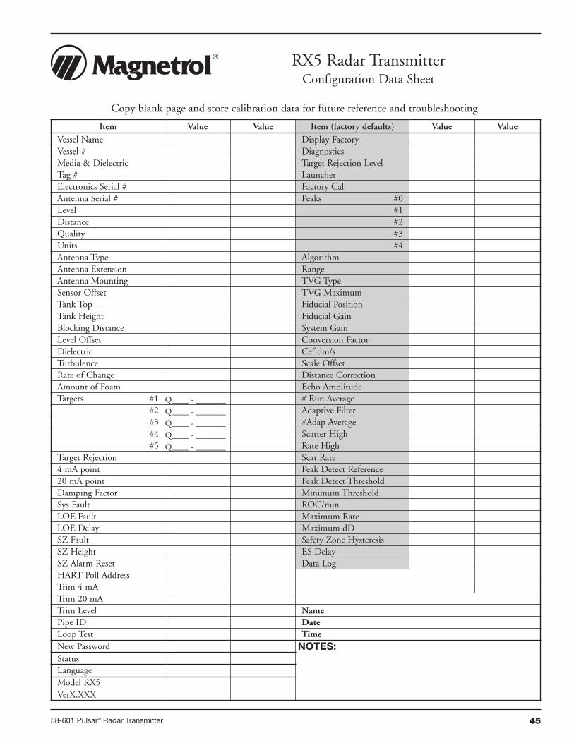
4558-601 Pulsar® Radar Transmitter
Item Value Value Item (factory defaults) Value ValueVessel Name Display FactoryVessel # DiagnosticsMedia & Dielectric Target Rejection LevelTag # LauncherElectronics Serial # Factory CalAntenna Serial # Peaks #0Level #1Distance #2Quality #3Units #4Antenna Type AlgorithmAntenna Extension RangeAntenna Mounting TVG TypeSensor Offset TVG MaximumTank Top Fiducial PositionTank Height Fiducial GainBlocking Distance System GainLevel Offset Conversion FactorDielectric Cef dm/sTurbulence Scale OffsetRate of Change Distance CorrectionAmount of Foam Echo AmplitudeTargets #1 Q____ - _______ # Run Average
#2 Q____ - _______ Adaptive Filter#3 Q____ - _______ #Adap Average#4 Q____ - _______ Scatter High#5 Q____ - _______ Rate High
Target Rejection Scat Rate4 mA point Peak Detect Reference20 mA point Peak Detect ThresholdDamping Factor Minimum ThresholdSys Fault ROC/minLOE Fault Maximum RateLOE Delay Maximum dDSZ Fault Safety Zone HysteresisSZ Height ES DelaySZ Alarm Reset Data LogHART Poll AddressTrim 4 mATrim 20 mATrim Level NamePipe ID DateLoop Test TimeNew Password NOTES:StatusLanguageModel RX5VerX.XXX
RX5 Radar TransmitterConfiguration Data Sheet
Copy blank page and store calibration data for future reference and troubleshooting.

58-601 Pulsar® Radar Transmitter
Notes

58-601 Pulsar® Radar Transmitter
Notes
BULLETIN: 58-601.5EFFECTIVE: August 2011SUPERSEDES: May 2007
Service Policy
Owners of MAGNETROL may request the return of acontrol or any part of a control for complete rebuilding orreplacement. They will be rebuilt or replaced promptly.Controls returned under our service policy must bereturned by Prepaid transportation. MAGNETROL willrepair or replace the control at no cost to the purchaser(or owner) other than transportation if:
1. Returned within the warranty period; and2. The factory inspection finds the cause of the claim to
be covered under the warranty.
If the trouble is the result of conditions beyond our con-trol; or, is NOT covered by the warranty, there will becharges for labor and the parts required to rebuild orreplace the equipment.
In some cases it may be expedient to ship replacementparts; or, in extreme cases a complete new control, toreplace the original equipment before it is returned. If thisis desired, notify the factory of both the model and serialnumbers of the control to be replaced. In such cases, cred-it for the materials returned will be determined on thebasis of the applicability of our warranty.
No claims for misapplication, labor, direct or consequen-tial damage will be allowed.
Return Material Procedure
So that we may efficiently process any materials that arereturned, it is essential that a “Return MaterialAuthorization” (RMA) number be obtained from the fac-tory, prior to the material’s return. This is available througha MAGNETROL local representative or by contacting thefactory. Please supply the following information:
1. Company Name2. Description of Material3. Serial Number4. Reason for Return5. Application
Any unit that was used in a process must be properlycleaned in accordance with OSHA standards, before it isreturned to the factory.
A Material Safety Data Sheet (MSDS) must accompanymaterial that was used in any media.
All shipments returned to the factory must be by prepaidtransportation.
All replacements will be shipped F.O.B. factory.
ASSURED QUALITY & SERVICE COST LESS
Magnetrol, Magnetrol logotype and Pulsar are registered trademarks of Magnetrol International, Incorporated.Viton® and Kalrez® are registered trademarks of DuPont Performance Elastomers.HART® is a registered trademark of the HART Communication FoundationPACTware™ is trademark of PACTware ConsortiumCSA logotype is a registered trademark of Canadian Standards AssociationHalar® is a registered trademark of Allied Chemical Corp.Hastelloy® is a registered trademark of Haynes International, Inc.Monel® is a registered trademark of Special Metals Corporation (Formerly Inco Alloys International)KYNAR® is a registered trademark of Pennsalt Chemicals Corp.Tri-Clover is a registered trademark of Tri-Clover, Inc.
5300 Belmont Road • Downers Grove, Illinois 60515-4499 • 630-969-4000 • Fax 630-969-9489 • www.magnetrol.com145 Jardin Drive, Units 1 & 2 • Concord, Ontario Canada L4K 1X7 • 905-738-9600 • Fax 905-738-1306Heikensstraat 6 • B 9240 Zele, Belgium • 052 45.11.11 • Fax 052 45.09.93Regent Business Ctr., Jubilee Rd. • Burgess Hill, Sussex RH15 9TL U.K. • 01444-871313 • Fax 01444-871317
Copyright © 2011 Magnetrol International, Incorporated. All rights reserved. Printed in the USA.Performance specifications are effective with date of issue and are subject to change without notice.
PULSAR Pulse Burst Radar transmitters may be protected by one or more of the following U.S. Patent Nos.:US 6,062,095; US 6,980,174; US 7,102,584; US 7,106,248; US 7,271,646
Top Related