


Languages
Pages
Legal


4 Modular FRL Series MX 3/8”, 1/2”, 3/4” and 1” NPTF Page
Series MX Summary and Features 132
Series MX Filters 134
Series MX Coalescing Filters 138
Series MX Activated Carbon Filters 142
Series MX Pressure Regulators 147
Series MX Lubricators 156
Series MX Filter-Regulators 159
44
MOD
ULAR
FRL
SER
IES
MX
130The company reserves the right to vary models and dimensions without notice.
These products are designed for industrial applications and are not suitable for sale to the general public.
Modular FRL Series MX NORTH AMERICAN FRL CATALOG >> Release 8.6

Series MX Lockable Isolation 3/2 Way Valves 163
Series MX Soft Start Valves 168
Series MX Take-Off Blocks 172
Series MX FRL Pre-Assembled 175
Series MX Pressure Gauges and Accessories 185
44
MODULAR FRL SERIES M
X
131The company reserves the right to vary models and dimensions without notice.These products are designed for industrial applications and are not suitable for sale to the general public.
Modular FRL Series MXNORTH AMERICAN FRL CATALOG >> Release 8.6

44
MOD
ULAR
FRL
SER
IES
MX
132The company reserves the right to vary models and dimensions without notice.
These products are designed for industrial applications and are not suitable for sale to the general public.
Modular FRL Series MX NORTH AMERICAN FRL CATALOG >> Release 8.6
Summary and FeaturesSeries MX - Modular 3/8" - 1" NPTF
Manual Shut-Off Valve w/ Lock-Out, Tag-Out• Downstream quick-dump feature• Lock-Out hole is 8mm ( 0.315" ) OD, to
accommodate most locks and hasps• Unit flows to downstream when handle is
down - Lifting handle exposes lock-out hole and exhausts downstream pressure
Filter• Coalescing, active carbon, 5 & 25 micron elements
available• Quick-Release bayonet bowls• Grilamid (Nylon Composite) outer shroud, inner
polycarbonate• Manual, Depressurizing & Automatic Float Drain
Options available• Visual filter blockage indicators optional• Thumb-latch on all bowls prevents accidental opening
of bowl
Regulator• Three Pressure range options• Relieving, Non-Relieving, and rapid
backflow diaphragm options• Factory Pressure presets avail.• Tamper-proof available (slots for
hard locks on all adjustment knobs)• Locking, Non-rising knob std.• Front & Rear gauge ports (pre-
installed gauges standard)
Optional Flanges/Endcaps• For easy removal of hard plumbing

44
MODULAR FRL SERIES M
X
133The company reserves the right to vary models and dimensions without notice.These products are designed for industrial applications and are not suitable for sale to the general public.
Modular FRL Series MXNORTH AMERICAN FRL CATALOG >> Release 8.6
Lubricator – • Venturi Design w/ 2 micron drop size• Flow adjustment near droplet indicator• Quick-release bayonet bowl• Grilamid (Nylon Composite) sight-glass material
w/ Nylon composite shroud over the inner polycarbonate
• Oil Refillable while pressurized• Large volume capacity bowl
Isolation / Soft-Start Valve Combo – • Solenoid or Air-Pilot activated• Downstream quick-dump feature• Fully adjustable pressure ramp-up during start-up• Port tap for electronic pressure switch (ex. PM11)• Poppet valve design Isolation/Soft-Start Valve• 1/2” - 3/4" Silencer ports on Shut-Off valves for Quick-Exhaust
feature
Standard Features – • Inlet Pressure 0.3 – 16 bar (4.25 – 232 psi)• Operating Temp (-5° C - 50° C, (23° F - 122° F), with Dew Point of air at least 2° C (4° F)
below the min working temperature)• Custom Assemblies available from McKinney, TX• Low Temp versions available• Aluminum construction w Polyurethane Enamel finish• Modular Design w/ Simple bracket assembly system• Single Part Number system for custom Assemblies
Optional Wallmount brackets
Standard assembly brackets

GENERAL DATA
Construction modular, compact with filtering element in HDPEMaterials see TABLE OF MATERIALS Ports 3/8" - 1" NPTFCondensate capacity MX3: 85 cc, (approx. 3 oz.), MX2: 55 cc (approx. 1.9 oz.)Mounting vertical in-line
wall-mounting (by means of clamps)Operating temperature -5°C - 50°C at 16 bar with Dew Point of air at least 2° C (4° F) below the min working temperature, (23 F - 122 F @ 232 psi, up to
140 F MAX at 145 psi)-5°C - 60°C at 10 bar with Dew Point of air at least 2° C (4° F) below the min working temperature
Delivered air quality(ISO 8573-1: 2010)
Class 6.8.4 with 5 μm elementClass 7.8.4 with 25 μm element
Draining of condensate manual, automatic, depressurizing and ported
Operating pressure 0.3 - 16 bar (with automatic drain 1.5 - 12 bar); (4.5 - 232 psi, with automatic drain 22 - 175 psi)Nominal flow see FLOW DIAGRAMSFluid compressed air
44
MOD
ULAR
FRL
SER
IES
MX
134The company reserves the right to vary models and dimensions without notice.
These products are designed for industrial applications and are not suitable for sale to the general public.
Modular FRL Series MX NORTH AMERICAN FRL CATALOG >> Release 8.6
FiltersSeries MX
Ports 3/8" - 1" NPTFMX2 ports: 3/8", 1/2", 3/4" NPTF - MX3 ports: 3/4", 1" NPTF Innovative modular clamping system Quick-Release, locking bayonet bowls
This modular FRL is characterized by a modern, compact design, and high performance. The integration between metal alloys and technopolymers has allowed the realization of a reliable product, both light and strong at the same time. The unique and patented modular clamping system simplifies the mounting of components.
The Series MX appeals to a broad spectrum of markets and applications because of the savings realized in installation time, space requirements and total cost.
A special configurator, available on Camozzi's global website at http://catalogue.camozzi.com (sec. Configurators), allows the customer to choose the most suitable solution for his application, selecting single components or by configuring assembled FRLs.
» Removal of impurities and condensate
» High flow with minimal pressure decreases
» Cartridge filters of 25 or 5 µm
» Manual, automatic, depressurizing and ported condensate drain
» Bowl locking mechanism reduces the risk of accidents
» Visual clog indicator option
44
MODULAR FRL SERIES M
X
135The company reserves the right to vary models and dimensions without notice.These products are designed for industrial applications and are not suitable for sale to the general public.
Modular FRL Series MXNORTH AMERICAN FRL CATALOG >> Release 8.6
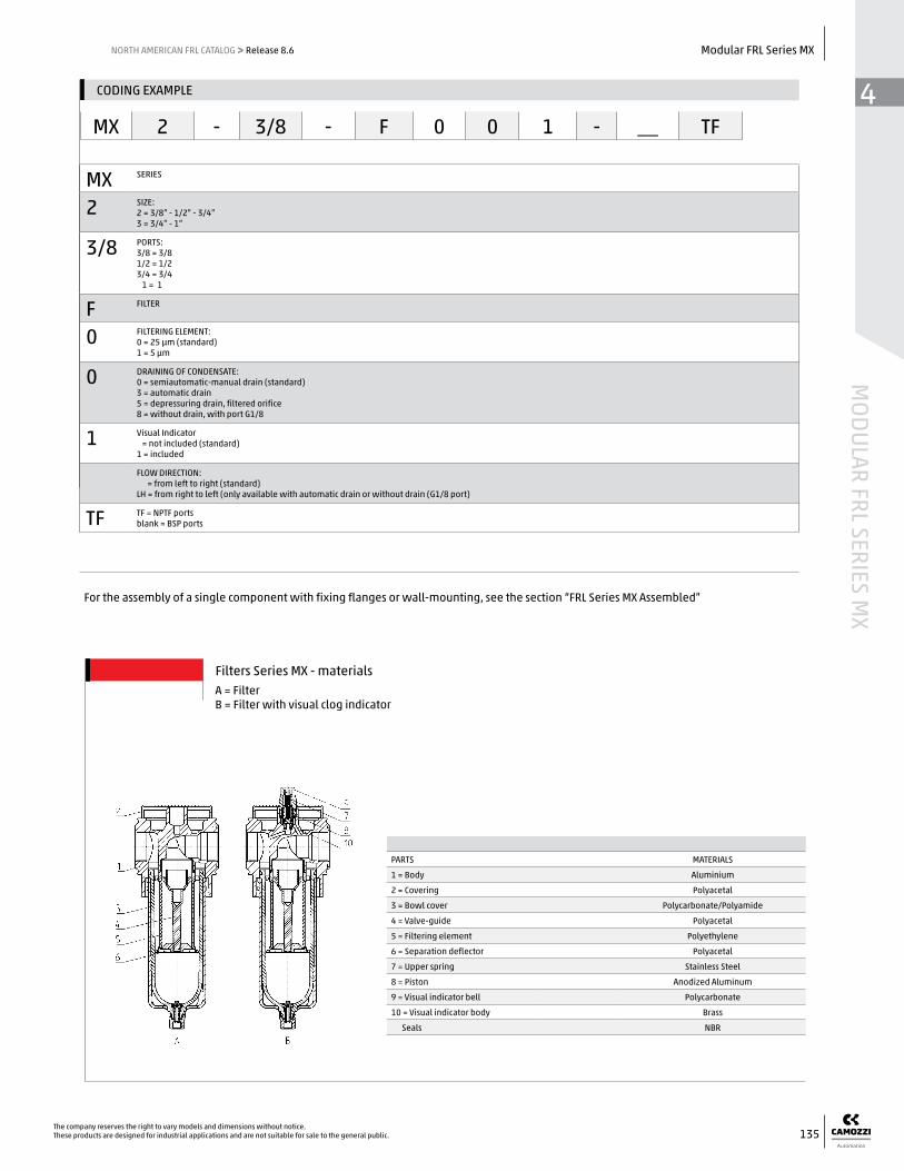
MX SERIES
2 SIZE:2 = 3/8” - 1/2” - 3/4”3 = 3/4” - 1”
3/8 PORTS:3/8 = 3/81/2 = 1/23/4 = 3/4 1 = 1
F FILTER
0 FILTERING ELEMENT:0 = 25 µm (standard)1 = 5 µm
0 DRAINING OF CONDENSATE:0 = semiautomatic-manual drain (standard)3 = automatic drain5 = depressuring drain, filtered orifice8 = without drain, with port G1/8
1 Visual Indicator = not included (standard)1 = included
FLOW DIRECTION: = from left to right (standard) LH = from right to left (only available with automatic drain or without drain (G1/8 port)
TF TF = NPTF portsblank = BSP ports
CODING EXAMPLE
MX 2 - 3/8 - F 0 0 1 - __ TF
A = FilterB = Filter with visual clog indicator
For the assembly of a single component with fixing flanges or wall-mounting, see the section “FRL Series MX Assembled”
Filters Series MX - materials
PARTS MATERIALS
1 = Body Aluminium
2 = Covering Polyacetal
3 = Bowl cover Polycarbonate/Polyamide
4 = Valve-guide Polyacetal
5 = Filtering element Polyethylene
6 = Separation deflector Polyacetal
7 = Upper spring Stainless Steel
8 = Piston Anodized Aluminum
9 = Visual indicator bell Polycarbonate
10 = Visual indicator body Brass
Seals NBR

44
MOD
ULAR
FRL
SER
IES
MX
136The company reserves the right to vary models and dimensions without notice.
These products are designed for industrial applications and are not suitable for sale to the general public.
Modular FRL Series MX NORTH AMERICAN FRL CATALOG >> Release 8.6
* Reference diagram for models with filtering element = 25 µm Δp = Pressure drop (bar) Q = Flow (Nl/min)
** Reference diagram for models with filtering element = 5 µm Δp = Pressure drop (bar) Q = Flow (Nl/min)
MX2 FILTERS FLOW DIAGRAMS
* Reference diagram for models with filtering element = 25 µm Δp = Pressure drop (bar) Q = Flow (Nl/min)
** Reference diagram for models with filtering element = 5 µm Δp = Pressure drop (bar) Q = Flow (Nl/min)
MX3 FILTERS FLOW DIAGRAMS

44
MODULAR FRL SERIES M
X
137The company reserves the right to vary models and dimensions without notice.These products are designed for industrial applications and are not suitable for sale to the general public.
Modular FRL Series MXNORTH AMERICAN FRL CATALOG >> Release 8.6
DIMENSIONS (in inches)
Mod. A C G I L M N O R S T Weight (kg)
MX2-3/8-F00-TF 3/8 2.756 2.177 2.677 1/8 2.264 8.346 5.000 3.346 6.870 1.476 0.5
MX2-1/2-F00-TF 1/2 2.756 2.177 2.677 1/8 2.264 8.346 5.000 3.346 6.870 1.476 0.5
MX2-3/4-F00-TF 3/4 2.756 2.177 2.677 1/8 2.264 8.346 5.000 3.346 6.870 1.476 0.5
MX3-3/4-F00-TF 3/4 3.524 2.421 2.992 1/8 2.953 9.488 5.591 3.898 7.736 1.752 0.8
MX3-1-F00-TF 1 3.524 2.421 2.992 1/8 2.953 9.488 5.591 3.898 7.736 1.752 0.7
Filters Series MX - dimensions
FT01 = filter without drain with threaded port
FT02 = filter with semiautomatic
manual drainFT03 = filter with automatic or depressuring drain
DIMENSIONS (in inches)
Mod. A C G I L M N O R S T Weight (kg)
MX2-3/8-F001-TF 3/8 2.756 2.177 2.677 1/8 2.264 9.094 5 4.094 6.870 2.224 0.5
MX2-1/2-F001-TF 1/2 2.756 2.177 2.677 1/8 2.264 9.094 5 4.094 6.870 2.224 0.5
MX2-3/4-F001-TF 3/4 2.756 2.177 2.677 1/8 2.264 9.094 5 4.094 6.870 2.224 0.5
MX3-3/4-F001-TF 3/4 3.523 2.42 2.992 1/8 2.953 10.236 5.59 4.646 7.736 2.5 0.8
MX3-1-F001-TF 1 3.523 2.42 2.992 1/8 2.953 10.236 5.59 4.646 7.736 2.5 0.7
Filters Series MX - dimensions
FT05 = filter without drain with threaded port and visual indicator
FT06 = filter with semiautomatic manual drain and visual clog indicator
FT07 = filter with automatic or depressuring drain and visual clog indicator
GENERAL DATA
Construction modular, compactMaterials see TABLE OF MATERIALSPorts 3/8" - 1" NPTFCondensate capacity MX3: 85 cc. (approx. 3 oz.), MX2: 55 cc (approx. 1.9 oz.)Mounting vertical in-line
wall-mounting (by means of clamps)Operating temperature -5°C - 50°C at 16 bar with Dew Point of air at least 2° C (4° F) below the min working temperature, (23° F -
122°F @ 232 psi, up to 140 F MAX at 145 psi)-5°C - 60°C at 10 bar with Dew Point of air at least 2° C (4° F) below the min working temperature
Draining of condensate manual, automatic, depressurizing and portedOperating pressure 0.3 - 16 bar (with automatic drain 1.5 - 12 bar); (4.5 - 232 psi, with automatic drain 22 - 175 psi)Nominal flow see FLOW DIAGRAMSDelivered air quality(ISO 8573-1: 2010)
Class 2.8.2 with 1 µm filter elementClass 1.8.1 with 0.01 µm filter element
Residual oil content with inlet at 3 mg/m3 < 0.01mg/m³ < 0.1mg/m³Oil retain efficiency 99.80% 97%Particles retain efficiency 99.99999% 99.999%Fluid compressed airPre-filtering with filtering element of 1 µmPre-filtering with filtering element of 0.01 µm
it is recommended to use a filter of 5 µmit is recommended to use a filter with residual oil of 0.1 mg/m³
44
MOD
ULAR
FRL
SER
IES
MX
138The company reserves the right to vary models and dimensions without notice.
These products are designed for industrial applications and are not suitable for sale to the general public.
Modular FRL Series MX NORTH AMERICAN FRL CATALOG >> Release 8.6
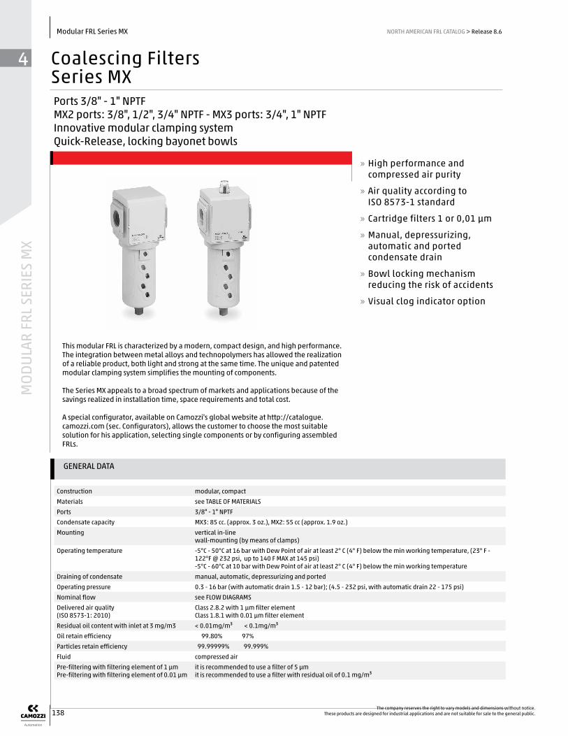
Coalescing FiltersSeries MXPorts 3/8" - 1" NPTFMX2 ports: 3/8", 1/2", 3/4" NPTF - MX3 ports: 3/4", 1" NPTF Innovative modular clamping system Quick-Release, locking bayonet bowls
» High performance and compressed air purity
» Air quality according to ISO 8573-1 standard
» Cartridge filters 1 or 0,01 μm
» Manual, depressurizing, automatic and ported condensate drain
» Bowl locking mechanism reducing the risk of accidents
» Visual clog indicator option
This modular FRL is characterized by a modern, compact design, and high performance. The integration between metal alloys and technopolymers has allowed the realization of a reliable product, both light and strong at the same time. The unique and patented modular clamping system simplifies the mounting of components.
The Series MX appeals to a broad spectrum of markets and applications because of the savings realized in installation time, space requirements and total cost.
A special configurator, available on Camozzi's global website at http://catalogue.camozzi.com (sec. Configurators), allows the customer to choose the most suitable solution for his application, selecting single components or by configuring assembled FRLs.
44
MODULAR FRL SERIES M
X
139The company reserves the right to vary models and dimensions without notice.These products are designed for industrial applications and are not suitable for sale to the general public.
Modular FRL Series MXNORTH AMERICAN FRL CATALOG >> Release 8.6
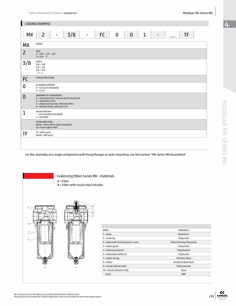
For the assembly of a single component with fixing flanges or wall-mounting, see the section “FRL Series MX Assembled”
Coalescing filters Series MX - materials
MX SERIES
2 SIZE:2 = 3/8" - 1/2" - 3/4"3 = 3/4" - 1"
3/8 PORTS:3/8 = 3/81/2 = 1/23/4 = 3/4 1 = 1
FC COALESCING FILTER
0 FILTERING ELEMENT:0 = 0,01 µm (standard)1 = 1 µm
0 DRAINING OF CONDENSATE:0 = semiautomatic-manual drain (standard)3 = automatic drain5 = depressuring drain, filtered orifice8 = without drain, with port 1/8
1 Visual Indicator = not included (standard)1 = included
FLOW DIRECTION: Blank = from left to right (standard) LH = from right to left
TF TF = NPTF portsblank = BSP ports
CODING EXAMPLE
MX 2 - 3/8 - FC 0 0 1 - __ TF
PARTS MATERIALS
1 = Body Aluminium
2 = Covering Polyacetal
3 = Bowl with technopolymer cover Polycarbonate/Polyamide
4 = Valve-guide Polyacetal
5 = Filtering element Polyethylene
6 = Separation deflector Polyacetal
7 = Upper spring Stainless Steel
8 = Piston Anodized Aluminum
9 = Visual indicator bell Polycarbonate
10 = Visual indicator body Brass
Seals NBR
A = FilterB = Filter with visual clog indicator

44
MOD
ULAR
FRL
SER
IES
MX
140The company reserves the right to vary models and dimensions without notice.
These products are designed for industrial applications and are not suitable for sale to the general public.
Modular FRL Series MX NORTH AMERICAN FRL CATALOG >> Release 8.6
MX2 FLOW DIAGRAMS
MX3 FLOW DIAGRAMS
* Reference diagram for models with filtering element = 0.01 μm Δp = Pressure drop (bar) Q = Flow (Nl/min)
** Reference diagram for models with filtering element = 1 μm Δp = Pressure drop (bar) Q = Flow (Nl/min)
* Reference diagram for models with filtering element = 0.01 μm Δp = Pressure drop (bar) Q = Flow (Nl/min)
** Reference diagram for models with filtering element = 1 μm Δp = Pressure drop (bar) Q = Flow (Nl/min)

44
MODULAR FRL SERIES M
X
141The company reserves the right to vary models and dimensions without notice.These products are designed for industrial applications and are not suitable for sale to the general public.
Modular FRL Series MXNORTH AMERICAN FRL CATALOG >> Release 8.6
Coalescing filters Series MX - dimensions
DIMENSIONS (in inches)
Mod. A C G I L M N O R S T Weight (kg)
MX2-3/8-FC00-TF 3/8 2.756 2.177 2.677 1/8 2.047 8.346 5.000 3.346 6.870 1.476 0.5
MX2-1/2-FC00-TF 1/2 2.756 2.177 2.677 1/8 2.047 8.346 5.000 3.346 6.870 1.476 0.5
MX2-3/4-FC00-TF 3/4 2.756 2.177 2.677 1/8 2.047 8.346 5.000 3.346 6.870 1.476 0.5
MX3-3/4-FC00-TF 3/4 3.524 2.421 2.992 1/8 2.953 9.488 5.591 3.898 7.736 1.752 0.8
MX3-1-FC00-TF 1 3.524 2.421 2.992 1/8 2.953 9.488 5.591 3.898 7.736 1.752 0.8
FA01 = coalescing filter without drain with threaded port
FA02 = coalescing filter with semiautomatic manual drain
FA03 = coalescing filter with automatic or depressuring drain
Coalescing filters Series MX - dimensions
DIMENSIONS (in inches)
Mod. A C G I L M N O R S T Weight (kg)
MX2-3/8-FC001-TF 3/8 2.756 2.177 2.677 1/8 2.047 9.094 5 4.094 6.870 2.224 0.5
MX2-1/2-FC001-TF 1/2 2.756 2.177 2.677 1/8 2.047 9.094 5 4.094 6.870 2.224 0.5
MX2-3/4-FC001-TF 3/4 2.756 2.177 2.677 1/8 2.047 9.094 5 4.094 6.870 2.224 0.5
MX3-3/4-FC001-TF 3/4 3.524 2.421 2.992 1/8 2.953 10.236 5.591 4.646 7.736 2.5 0.8
MX3-1-FC001-TF 1 3.524 2.421 2.992 1/8 2.953 10.236 5.591 4.646 7.736 2.5 0.8
FA01 = coalescing filter without drain with threaded port and visual clog indicator
FA02 = coalescing filter with semiautomatic manual drain and visual clog indicator
FA03 = coalescing filter with automatic or depressuring drain and visual clog indicator

GENERAL DATA
Construction modular, compact with activated carbon filtering elementMaterials see TABLE OF MATERIALSPorts 3/8" - 1" NPTFMounting vertical in-line
wall-mounting (by means of clamps)Operating temperature 10°C - 40°C (t max = 60°C), (50°F - 105 F, max temp. 140°F)Draining of condensate NO DRAININGOperating pressure 0.3 - 16 bar (4.5 - 232 psi)Nominal flow see FLOW DIAGRAMSFiltering element Class 1.7.1Residual oil content < 0.003 mg/m³Fluid compressed airPre-filtering it is recommended to use a coalescing filter with residual oil of 0,01mg/m³
44
MOD
ULAR
FRL
SER
IES
MX
142The company reserves the right to vary models and dimensions without notice.
These products are designed for industrial applications and are not suitable for sale to the general public.
Modular FRL Series MX NORTH AMERICAN FRL CATALOG >> Release 8.6
Activated Carbon FiltersSeries MXPorts 3/8" - 1" NPTFMX2 ports: 3/8", 1/2", 3/4" NPTF - MX3 ports: 3/4", 1" NPTF Innovative modular clamping system Quick-Release, locking bayonet bowls
» Removal of compressed air oil, liquid, and gas components through the active carbons
» Air quality conforming to ISO 8573-1 standard, up to class 1.7.1
» Bowl locking mechanism reducing the risk of accidents
» Visual clog indicator option
This modular FRL is characterized by a modern, compact design, and high performance. The integration between metal alloys and technopolymers has allowed the realization of a reliable product, both light and strong at the same time. The unique and patented modular clamping system simplifies the mounting of components.
The Series MX appeals to a broad spectrum of markets and applications because of the savings realized in installation time, space requirements and total cost.
A special configurator, available on Camozzi's global website at http://catalogue.camozzi.com (sec. Configurators), allows the customer to choose the most suitable solution for his application, selecting single components or by configuring assembled FRLs.

44
MODULAR FRL SERIES M
X
143The company reserves the right to vary models and dimensions without notice.These products are designed for industrial applications and are not suitable for sale to the general public.
Modular FRL Series MXNORTH AMERICAN FRL CATALOG >> Release 8.6
For the assembly of a single component with fixing flanges or wall-mounting, see the section “FRL Series MX Assembled”
Activated carbon filters Series MX - materials
PARTS MATERIALS
1 = Body Aluminium
2 = Covering Polyacetal
3 = Bowl cover Polycarbonate / Polyamide
4 = Filtering element Active carbon
5 = Upper spring Stainless steel
6 = Piston Anodized aluminum
7 = Viewer Polycarbonate
8 = Indicator body Brass
Seals NBR
MX SERIES
2 SIZE:2 = 3/8” - 1/2” - 3/4”3 = 3/4” - 1”
3/8 PORT:3/8 = 3/81/2 = 1/23/4 = 3/4 1 = 1
FCA ACTIVATED CARBON FILTER
1 VISUAL BLOCKAGE INDICATOR:Blank = not present1 = present
FLOW DIRECTION: = from left to right (standard) LH = from right to left
TF TF = NPTF portsblank = BSP ports
CODING EXAMPLE
MX 2 - 3/8 - FCA 1 - __ TF

44
MOD
ULAR
FRL
SER
IES
MX
144The company reserves the right to vary models and dimensions without notice.
These products are designed for industrial applications and are not suitable for sale to the general public.
Modular FRL Series MX NORTH AMERICAN FRL CATALOG >> Release 8.6
DIMENSIONS (in inche-s)
Mod. A C G I M N O R S T Weight (kg)
MX2-3/8-FCA-TF 3/8 2.756 2.177 2.677 3.524 7.461 4.114 3.346 5.984 1.476 0.5
MX2-1/2-FCA-TF 1/2 2.756 2.177 2.677 3.524 7.461 4.114 3.346 5.984 1.476 0.5
MX2-3/4-FCA-TF 3/4 2.756 2.177 2.677 3.524 7.461 4.114 3.346 5.984 1.476 0.5
MX3-3/4-FCA-TF 3/4 3.524 2.421 2.992 4.213 8.740 4.843 3.898 6.988 1.752 0.8
MX3-1-FCA-TF 1 3.524 2.421 2.992 4.213 8.740 4.843 3.898 6.988 1.752 0.8
ΔP = Pressure dropQ = Flow
FLOW DIAGRAMS, MX3 & MX2
Activated carbon filters Series MX - dimensions
Inlet pressure2 bar = 29 psi4 bar = 58 psi6 bar = 87 psi8 bar = 116 psi
psi bar
7.3 0.5
5.8 0.4
4.4 0.3
2.9 0.2
1.5 0.1
00 1000 2000 3000 4000 5000 Q (Nl/min) 35 70 105 140 175 Air Flow (SCFM)
2 bar
Δp = Pressure dropQ = Flow
psi bar
73 0.5
58 0.4
44 0.3
29 0.2
15 0.1
00 1000 2000 3000 4000 5000 Q (Nl/min) 35 70 105 140 175 Air Flow (SCFM)
MX3 flow curves MX2 flow curves
44
MODULAR FRL SERIES M
X
145The company reserves the right to vary models and dimensions without notice.These products are designed for industrial applications and are not suitable for sale to the general public.
Modular FRL Series MXNORTH AMERICAN FRL CATALOG >> Release 8.6
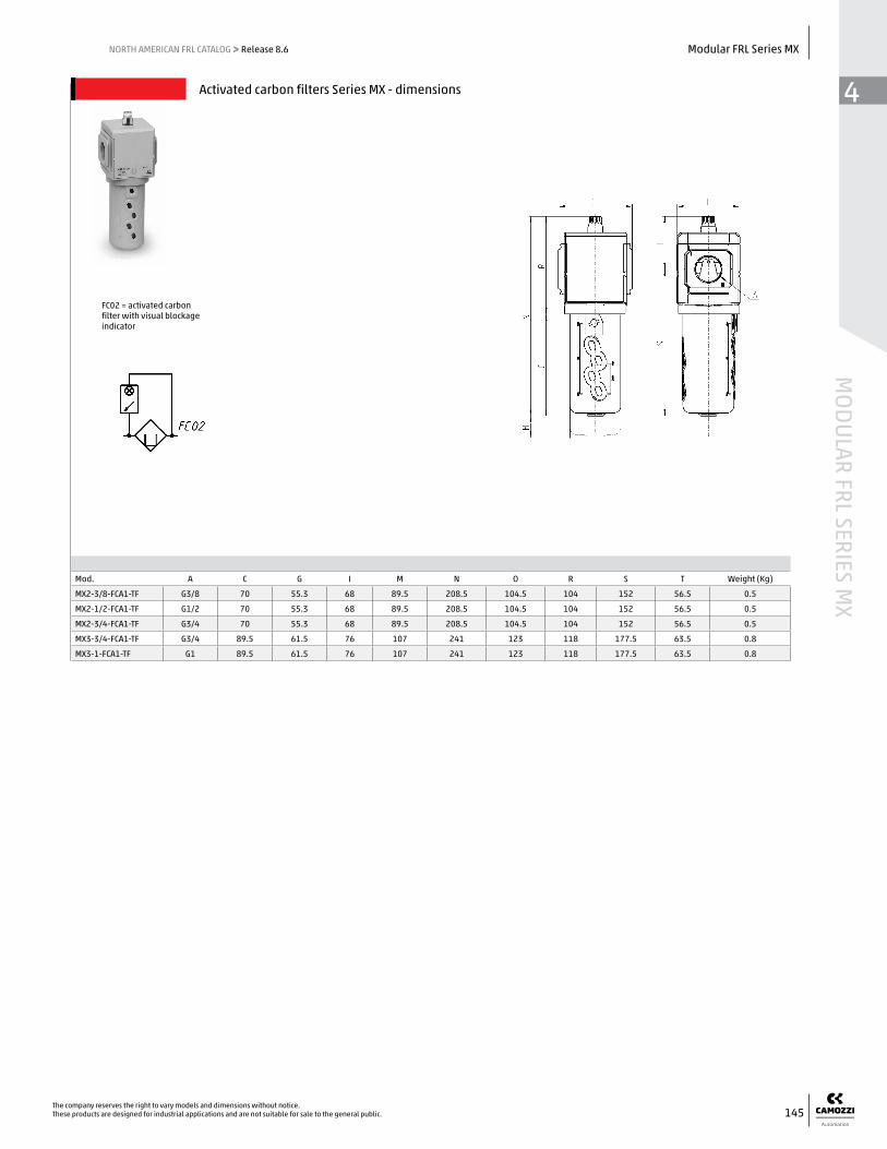
FC02 = activated carbon filter with visual blockage indicator
Activated carbon filters Series MX - dimensions
Mod. A C G I M N O R S T Weight (Kg)
MX2-3/8-FCA1-TF G3/8 70 55.3 68 89.5 208.5 104.5 104 152 56.5 0.5
MX2-1/2-FCA1-TF G1/2 70 55.3 68 89.5 208.5 104.5 104 152 56.5 0.5
MX2-3/4-FCA1-TF G3/4 70 55.3 68 89.5 208.5 104.5 104 152 56.5 0.5
MX3-3/4-FCA1-TF G3/4 89.5 61.5 76 107 241 123 118 177.5 63.5 0.8
MX3-1-FCA1-TF G1 89.5 61.5 76 107 241 123 118 177.5 63.5 0.8

44
MOD
ULAR
FRL
SER
IES
MX
146The company reserves the right to vary models and dimensions without notice.
These products are designed for industrial applications and are not suitable for sale to the general public.
Modular FRL Series MX NORTH AMERICAN FRL CATALOG >> Release 8.6

GENERAL DATA
Construction modular, compact, diaphragm typeMaterials see TABLE OF MATERIALSPorts 3/8" - 1" NPTFMounting vertical in-line
wall-mounting (by means of clamps)panel mouting
Operating temperature -5°C - 50°C at 16 bar with Dew Point of air at least 2° C (4° F) below the min working temperature, (23 F - 122 F @ 232 psi, up to 140 F MAX at 145 psi )-5°C - 60°C at 10 bar with Dew Point of air at least 2° C (4° F) below the min working temperature
Inlet pressure 0 - 16 bar (0 - 232 psi )Outlet pressure 0,5 - 10 bar, (7 - 145 psi) or
0 - 4 bar, (0 - 60 psi) 0.5 - 7 bar (7 - 102 psi) (MX2 only)
Overpressure exhaust with relieving orwithout relieving
Nominal flow see FLOW DIAGRAMSFluid compressed airPressure gauge version with built-in pressure gauge or
version with threaded gauge ports (1/8" on MX2 and 1/4" on MX3)
44
MODULAR FRL SERIES M
X
147The company reserves the right to vary models and dimensions without notice.These products are designed for industrial applications and are not suitable for sale to the general public.
Modular FRL Series MXNORTH AMERICAN FRL CATALOG >> Release 8.6
Pressure RegulatorsSeries MXStandard Regulators MX2 ports: 3/8", 1/2", 3/4" NPTF - MX3 ports: 3/4", 1" NPTF Manifold mount design: 1/2" NPTF (MX2 only) Innovative modular clamping system Available with built-in pressure gauges or with threaded ports for gauges
» Low set-point variance, or hysteresis
» Lockable knob with adjustment stop
» Tamper-proof system via slots in handle offers a fully lockable regulator
» Integral return exhaust (relieving)
» Available as Manifold regulator, non-cascading
Reliable and repeatable set-points of the secondary reduced pressure ensures performance optimization and energy saving. Available in 2 standard spring options for regulated pressure ranges. All regulators are equipped with an integrated locking system and built-in pressure gauges for a more compact product. The regulators Series MX are suitable also for panel mountings.
The Series MX appeals to a broad spectrum of markets and applications because of the savings realized in installation time, space requirements and total cost.
A special configurator, available on Camozzi's global website at http://catalogue.camozzi.com (sec. Configurators), allows the customer to choose the most suitable solution for his application, selecting single components or by configuring assembled FRLs.

44
MOD
ULAR
FRL
SER
IES
MX
148The company reserves the right to vary models and dimensions without notice.
These products are designed for industrial applications and are not suitable for sale to the general public.
Modular FRL Series MX NORTH AMERICAN FRL CATALOG >> Release 8.6
MX SERIES
2 SIZE:2 = 3/8” - 1/2” - 3/4”3 = 3/4” - 1”
3/8 PORTS:3/8 = 3/81/2 = 1/23/4 = 3/4 1 = 1
R TYPER OF REGULATOR:R = pressure regulatorM = Manifold pressure regulator (MX2 - 1/2” NPTF only)
0 OPERATING PRESSURE (1 bar = 14,5 psi)0 = 0,5 - 10 bar (7.25 - 145 psi)4 = 0 - 4 bar (0 - 58 psi)7 = 0.5 - 7 bar (MX2 only) (7.25 - 103 psi)
0 DESIGN TYPE:0 = relieving1 = without relieving 2 = relieving, with by-pass valve 3 = without relieving, with by-pass valve
4 PRESSURE GAUGE:0 = without pressure gauge (with threaded port for gauges)2 = with built-in pressure gauge 0-6 bar and working pressure 0 - 4 bar3 = with built-in pressure gauge 0-10 bar and working pressure 0 - 7 bar (MX2 only)4 = with built-in pressure gauge 0-12 bar and working pressure 0.5 - 10 bar
FLOW DIRECTION: = from left to right (standard) LH = from right to left
TF TF = NPTF portsblank = BSP ports
For the assembly of a single component with fixing flanges or wall-mounting, see the section “FRL Series MX Assembled”
CODING EXAMPLE
MX 2 - 3/8 - R 0 0 4 - __ TF
PARTS MATERIALS
1 = Body Aluminium
2 = Covering Polyacetal
3 = Valve holder plug Polyacetal
4 = Regulator knob Polyamide
5 = Upper spring Zinc-plated steel
6 = Diaphragm NBR
7 = Lower spring Stainless steel
Seals NBR
Pressure regulators Series MX - materialsR = pressure regulatorM = Manifold pressure regulator

44
MODULAR FRL SERIES M
X
149The company reserves the right to vary models and dimensions without notice.These products are designed for industrial applications and are not suitable for sale to the general public.
Modular FRL Series MXNORTH AMERICAN FRL CATALOG >> Release 8.6
Pr = Regulated PressureQ = Flow
Pa = Inlet pressure
MX3 FLOW DIAGRAMS
0 2000 4000 6000 8000 10000 Q (Nl/min) 70 140 210 280 350 Air Flow (SCFM)
psi bar
116 8
102 7
87 6
73 5
58 4
44 3
29 2
15 1
0
Inlet pressure = 145 psiPr (bar)
Pr = Regulated pressureQ = Flow
Pa = Inlet pressure
Pr = Regulated pressureQ = Flow
Pa = Inlet pressure
MX2 FLOW DIAGRAMS
0 2000 4000 6000 8000 Q (Nl/min) 70 140 210 280 Air Flow (SCFM)
0 2000 4000 6000 8000 Q (Nl/min) 70 140 210 280 Air Flow (SCFM)
psi bar
116 8
102 7
87 6
73 5
58 4
44 3
29 2
15 1
0
psi bar
116 8
102 7
87 6
73 5
58 4
44 3
29 2
15 1
0
&&

44
MOD
ULAR
FRL
SER
IES
MX
150The company reserves the right to vary models and dimensions without notice.
These products are designed for industrial applications and are not suitable for sale to the general public.
Modular FRL Series MX NORTH AMERICAN FRL CATALOG >> Release 8.6
Pressure regulators Series MX - dimensions
DIMENSIONS (in inches)
Mod. A B C D E F G H I M N P Q R S T UWeight
(kg)
MX2-3/8-R004-TF 3/8 0-12 bar 2.756 1.772 Ø 5/32” M47x1.5 2.756 2.933 2.677 1.772 6.535 3.071 0.197 3.465 1.988 1.476 0-13 0.6
MX2-1/2-R004-TF 1/2 0-12 bar 2.756 1.772 Ø 5/32” M47x1.5 2.756 2.933 2.677 1.772 6.535 3.071 0.197 3.465 1.988 1.476 0-13 0.6
MX2-3/4-R004-TF 3/4 0-12 bar 2.756 1.772 Ø 5/32” M47x1.5 2.756 2.933 2.677 1.772 6.535 3.071 0.197 3.465 1.988 1.476 0-13 0.6
MX3-3/4-R004-TF 3/4 0-12 bar 3.524 2.126 Ø 5/32” M57x1.5 2.953 3.189 2.992 1.772 8.110 4.094 0.197 4.016 2.264 1.752 0-20 1
MX3-1-R004-TF 1 0-12 bar 3.524 2.126 Ø 5/32” M57x1.5 2.953 3.189 2.992 1.772 8.110 4.094 0.197 4.016 2.264 1.752 0-20 1
PR01 = regulator without relieving PR02 = regulator with relieving PR03 = regulator with relieving and by-pass valve PR04 = regulator without relieving with by-pass valve PR05 = regulator without relieving and with pressure gauge PR06 = regulator with relieving and pressure gauge PR07 = regulator with relieving, by-pass valve and pressure gauge PR08 = reg. without reliev. with by-pass valve and pressure gauge

44
MODULAR FRL SERIES M
X
151The company reserves the right to vary models and dimensions without notice.These products are designed for industrial applications and are not suitable for sale to the general public.
Modular FRL Series MXNORTH AMERICAN FRL CATALOG >> Release 8.6
PR01 = regulator without relieving PR02 = regulator with relieving PR03 = regulator with relieving and by-pass valve PR04 = regulator without relieving with by-pass valve PR05 = regulator without relieving and with pressure gauge PR06 = regulator with relieving and pressure gauge PR07 = regulator with relieving, by-pass valve and pressure gauge PR08 = reg. without reliev. with by-pass valve and pressure gauge
Pr = Regulated pressureQ = Flow
Pa = Inlet pressure
FR19 = Manifold regulator with relieving and without gaugeFR20 = Manifold regulator with relieving and gaugeFR21 = Manifold regulator without relieving or gauge FR22 = Manifold regulator without relieving and with gauge
MANIFOLD REGULATOR - FLOW DIAGRAM and PNEUMATIC SYMBOLS
DIMENSIONS (in inches)
Mod. A B C D E F G H I M N P Q R S T U VWeight
(kg)
MX2-1/2-M004 1/2 0-12 bar 2.756 1.772 5/32” M47x1.5 2.756 2.972 2.677 1.772 6.535 3.071 0.197 3.465 1.988 1.476 0-13 G 1/2 0.6
The picture on the left side shows that it is possibile to assemble a certain numer of regulators with the same inlet pressure using proper mounting kits, with or without flanges.The regulation of the outlet pressure (OUT port) of each regulator can be set by rotating the knob clockwise or counterclockwise until the desired pressure is reached.This regulation has no effect on the inlet pressure of regulators mounted downstream.
MANIFOLD pressure regulator Series MX - dimensions
psi
116 8
102 7
87 6
73 5
58 4
44 3
29 2
15 1
00 2000 4000 6000 8000 Qn (Nl/min) 70 140 210 280 Air Flow (SCFM)
New 44
MOD
ULAR
FRL
SER
IES
MX
152The company reserves the right to vary models and dimensions without notice.
These products are designed for industrial applications and are not suitable for sale to the general public.
Modular FRL Series MX NORTH AMERICAN FRL CATALOG >> Release 8.6
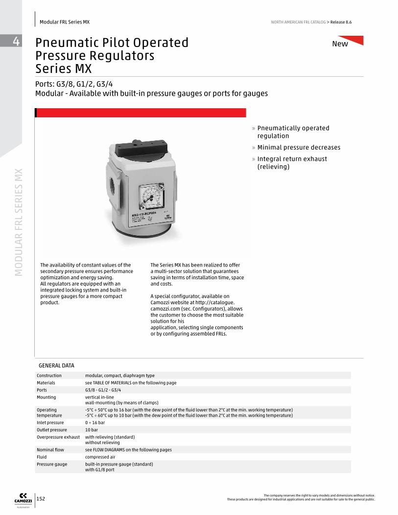
Pneumatic Pilot OperatedPressure RegulatorsSeries MXPorts: G3/8, G1/2, G3/4 Modular - Available with built-in pressure gauges or ports for gauges
The availability of constant values of the secondary pressure ensures performance optimization and energy saving. All regulators are equipped with an integrated locking system and built-in pressure gauges for a more compact product.
The Series MX has been realized to offer a multi-sector solution that guarantees saving in terms of installation time, space and costs. A special configurator, available on Camozzi website at http://catalogue.camozzi.com (sec. Configurators), allows the customer to choose the most suitable solution for his application, selecting single components or by configuring assembled FRLs.
» Pneumatically operated regulation
» Minimal pressure decreases
» Integral return exhaust (relieving)
GENERAL DATA
Construction modular, compact, diaphragm typeMaterials see TABLE OF MATERIALS on the following pagePorts G3/8 - G1/2 - G3/4Mounting vertical in-line
wall-mounting (by means of clamps)Operating temperature
-5°C ÷ 50°C up to 16 bar (with the dew point of the fluid lower than 2°C at the min. working temperature) -5°C ÷ 60°C up to 10 bar (with the dew point of the fluid lower than 2°C at the min. working temperature)
Inlet pressure 0 ÷ 16 barOutlet pressure 10 barOverpressure exhaust with relieving (standard)
without relievingNominal flow see FLOW DIAGRAMS on the following pagesFluid compressed airPressure gauge built-in pressure gauge (standard)
with G1/8 port

44
MODULAR FRL SERIES M
X
153The company reserves the right to vary models and dimensions without notice.These products are designed for industrial applications and are not suitable for sale to the general public.
Modular FRL Series MXNORTH AMERICAN FRL CATALOG >> Release 8.6
MX SERIES
2 SIZE: 2 = G3/8 - G1/2 - G3/4
1/2 PORTS: 3/8 = G3/8 1/2 = G1/2 3/4 = G3/4
R TYPER OF REGULATOR: R = pressure regulator
CP TYPE OF COMMAND/PILOT SUPPLY: CP = pneumatic pilot supply
0 OPERATING PRESSURE: 0 = 7 - 145 psi (0.5 - 10 bar)
0 DESIGN TYPE: 0 = relieving (standard) 1 = without relieving
4 PRESSURE GAUGE: 0 = without pressure gauge (with threaded port for gauges) 4 = with built-in pressure gauge 0-12 and working pressure 0.5 ÷ 10 bar (standard)
FLOW DIRECTION: = from left to right (standard) LH = from right to left
TF TF = NPTF portsblank = BSP ports
For the assembly of a single component with fixing flanges or wall-mounting, see the section “FRL Series MX Assembled”
MX 2 - 1/2 - R CP 0 0 4 - __ - TF
PARTS MATERIALS
1 = Body Aluminium
2 = Covering Polyacetal
3 = Valve holder plug Polyacetal
4 = Upper base Polyamide
5 = Lower spring Stainless steel
6 = Diaphragm NBR
Seals NBR
Pneumatic pilot operated pressure regulators Series MX - materials
CODING EXAMPLE

44
MOD
ULAR
FRL
SER
IES
MX
154The company reserves the right to vary models and dimensions without notice.
These products are designed for industrial applications and are not suitable for sale to the general public.
Modular FRL Series MX NORTH AMERICAN FRL CATALOG >> Release 8.6
Pr = Regulated pressure (bar) Q = Flow (Nl/min) Inlet pressure = 10bar
Pr = Regulated pressure (bar) Q = Flow (Nl/min) Inlet pressure = 10bar
DIAGRAMS OF PNEUMATIC PILOT OPERATED PRESSURE REGULATORS
Pr = Regulated pressure (bar) Q = Flow (Nl/min) Inlet pressure = 10bar
ADJUSTMENT CURVE Pr = regulated pressure (bar) Pp = pilot pressure (bar) Inlet pressure = 10bar
2000 4000 6000 70 140 210
psi bar
116 8
102 7
87 6
73 5
58 4
44 3
29 2
15 1
0
psi bar
116 8
102 7
87 6
73 5
58 4
44 3
29 2
15 1
00 0
Air Flow (SCFM)Q (Nl/min) 2000 4000 6000 8000
70 140 210 280 Air Flow (SCFM)Q (Nl/min)
Air Flow (SCFM)Q (Nl/min)

44
MODULAR FRL SERIES M
X
155The company reserves the right to vary models and dimensions without notice.These products are designed for industrial applications and are not suitable for sale to the general public.
Modular FRL Series MXNORTH AMERICAN FRL CATALOG >> Release 8.6
Pneumatic pilot operated pressure regulators Series MX - dimensions
Mod. A B (bar) C G H I M Y (Pilot supply) N P R S T Weight (Kg)
MX2-3/8-RCP004-TF 3/8 0 - 12 70 65 74.5 68 45 M5 98 10 88 50.5 37.5 0.5
MX2-1/2-RCP004-TF 1/2 0 - 12 70 65 74.5 68 45 M5 98 10 88 50.5 37.5 0.5
MX2-3/4-RCP004-TF 3/4 0 - 12 70 65 74.5 68 45 M5 98 10 88 50.5 37.5 0.5
PR09 = reg. with relieving PR10 = regulator with relieving and pressure gauge PR11 = regulator without relieving PR12 = regulator without relieving and with pressure gauge

GENERAL DATA
Construction modular, compactMaterials see TABLE OF MATERIALSPorts 3/4" - 1" NPTFOil capacity MX3: 170 cc (5.75 oz), MX2: 118 cc ( 4.0 oz.)Oil refilling while under system pressure allowed by means of cap screw in head, or directly into bowl without pressureMounting vertical in-line
wall-mounting (by means of clamps)Operating temperature -5°C - 50°C at 16 bar (with Dew Point of air at least 2° C (4° F) below the min working temperature), (23 F - 122
F @ 232 psi, up to 140 F MAX at 145 psi)-5°C - 60°C at 10 bar (with Dew Point of air at least 2° C (4° F) below the min working temperature)
Oil for lubrication Use ISO VG32 oils. 3°E - 10°E , Engler (approx 32 centistokes) recommendation 1 - 5 drops every 1000 Nl of air consumed (35 SCFM) (10 drops = 1 mL = 1cm3 =.061 in3)
Droplet Size > 2 micronsOperating pressure 0 - 16 bar (0 - 232 psi)Min. air consumption for lubrication at 1 bar MX2: 17 Nl/min (0.6 SCFM)
MX3: 50 NL/min (1.75 SCFM)Min. air consumption for lubrication at 6 bar MX2: 38 Ml/min (1.3 SCFM)
MX3: 90 Nl/min (3.1 SCFM)Nominal flow See FLOW DIAGRAMS on the following pages
44
MOD
ULAR
FRL
SER
IES
MX
156The company reserves the right to vary models and dimensions without notice.
These products are designed for industrial applications and are not suitable for sale to the general public.
Modular FRL Series MX NORTH AMERICAN FRL CATALOG >> Release 8.6
LubricatorsSeries MXPorts 3/8" - 1" NPTFMX2 ports: 3/8", 1/2", 3/4" NPTF - MX3 ports: 3/4", 1" NPTF Innovative modular clamping system Quick-Release, locking bayonet bowls
» Oil adjustment screw in sight glass
» Ability to refill the oil even with system under pressure
» High flow
» Oil level visible through transparent slots in bowl shroud
» Bowl locking mechanism
» Enhanced safety features
This modular FRL is characterized by a modern, compact design, and high performance. The integration between metal alloys and technopolymers has allowed the realization of a reliable product, both light and strong at the same time. The unique and patented modular clamping system simplifies the mounting of components.
The Series MX appeals to a broad spectrum of markets and applications because of the savings realized in installation time, space requirements and total cost.
A special configurator, available on Camozzi's global website at http://catalogue.camozzi.com (sec. Configurators), allows the customer to choose the most suitable solution for his application, selecting single components or by configuring assembled FRLs.

44
MODULAR FRL SERIES M
X
157The company reserves the right to vary models and dimensions without notice.These products are designed for industrial applications and are not suitable for sale to the general public.
Modular FRL Series MXNORTH AMERICAN FRL CATALOG >> Release 8.6
For the assembly of a single component with fixing flanges or wall-mounting, see the section “FRL Series MX Assembled”
Lubricators Series MX - materials
PARTS MATERIALS
1 = Body Aluminium
2 = Covering Polyacetal
3 = Bowl with technopolymer cover Polycarbonate/Polyamide
4 = Diaphragm NBR
5 = Viewer Polyamide
Seals NBR
MX SERIES
2 SIZE:2 = 3/8” - 1/2” - 3/4”3 = 3/4” - 1”
3/8 PORT:1/2 = 1/23/4 = 3/4 1 = 1
L LUBRICATOR
00 DESIGN TYPE:00 = atomized oil
FLOW DIRECTION: = from left to right (standard) LH = from right to left
TF TF = NPTF portsblank = BSP ports
CODING EXAMPLE
MX 2 - 3/8 - L 00 - TF

44
MOD
ULAR
FRL
SER
IES
MX
158The company reserves the right to vary models and dimensions without notice.
These products are designed for industrial applications and are not suitable for sale to the general public.
Modular FRL Series MX NORTH AMERICAN FRL CATALOG >> Release 8.6
DIMENSIONS (in inches)
Mod. A C D G I M N O P R S TWeight (Kg)
MX2-3/8-L00-TF 3/8 2.756 0.728 2.185 2.677 3.327 8.268 4.114 0.807 3.346 5.984 1.476 0.5
MX2-1/2-L00-TF 1/2 2.756 0.728 2.185 2.677 3.327 8.268 4.114 0.807 3.346 5.984 1.476 0.5
MX2-3/4-L00-TF 3/4 2.756 0.728 2.185 2.677 3.327 8.268 4.114 0.807 3.346 5.984 1.476 0.5
MX3-3/4-L00-TF 3/4 3.524 0.728 2.421 2.992 3.937 9.567 4.843 0.827 3.898 7.008 1.752 0.8
MX3-1-L00-TF 1 3.524 0.728 2.421 2.992 3.937 9.567 4.843 0.827 3.898 7.008 1.752 0.8
FLOW DIAGRAMS, MX2 & MX3
Lubricators Series MX - dimensions
ΔP = Pressure dropQ = Flow
Δp = Pressure dropQ = Flow
MX2 flow curves MX3 flow curves

GENERAL DATA
Construction modular, compact with filtering element in HDPEMaterials see TABLE OF MATERIALSPorts 3/8" - 1" NPTFCondensate capacity MX3: 85 cc, (approx. 3 oz.), MX2: 55 cc ( approx. 1.9 oz. )Mounting vertical in-line
wall-mounting (by means of clamps)panel mounting
Operating temperature -5°C - 50°C at 16 bar (with Dew Point of air at least 2° C (4° F) below the min working temperature), (23 F - 122 F @ 232 psi, up to 140 F MAX at 145 psi )-5°C - 60°C at 10 bar (with Dew Point of air at least 2° C (4° F) below the min working temperature)
Delivered air quality(ISO 8573-1: 2010)
Class 6.8.4 with 5 µm filter elementClass 7.8.4 with 25 µm filter element
Draining of condensate manual, automatic, depressurizing and portedOperating pressure 0.3 - 16 bar (with automatic drain 1.5 - 12 bar); (4.5 - 232 psi, with automatic drain 22 - 175 psi)Nominal flow see FLOW DIAGRAMSFluid compressed airPressure gauge version with built-in pressure gauge or
version with threaded gauge ports (1/8" on MX2 and 1/4" on MX3)
44
MODULAR FRL SERIES M
X
159The company reserves the right to vary models and dimensions without notice.These products are designed for industrial applications and are not suitable for sale to the general public.
Modular FRL Series MXNORTH AMERICAN FRL CATALOG >> Release 8.6
Filter-RegulatorsSeries MXPorts 3/8" - 1" NPTFMX2 ports: 3/8", 1/2", 3/4" NPTF - MX3 ports: 3/4", 1" NPTF Innovative modular clamping system Quick-Release, locking bayonet bowls
Filter-regulators Series MX integrate filter and pressure regulator in one unit. They are, therefore, compact and suitable for pre-filtering functions.
Available in relieving or non-relieving, they are equipped with a valve diaphragm for a direct pressure regulation and with an integrated condensate drain, manual, automatic, depressurizing and ported. Moreover, they can be equipped with a built-in pressure gauge.
The Series MX has been realized to offer a multi-sector solution that guarantees saving in terms of installation time, space and costs. A special configurator, available on Camozzi's global website at http://catalogue.camozzi.com (sec. Configurators), allows the customer to choose the most suitable solution for his application, selecting single components or by configuring assembled FRLs.
» Filtering element options of 25 µm or 5 µm
» Available versions: with built-in gauge or with ports for gauge
» Lockable knob with mechanical stop and tamper-proof lock-out features
» Bowl locking mechanism

44
MOD
ULAR
FRL
SER
IES
MX
160The company reserves the right to vary models and dimensions without notice.
These products are designed for industrial applications and are not suitable for sale to the general public.
Modular FRL Series MX NORTH AMERICAN FRL CATALOG >> Release 8.6
For the assembly of a single component with fixing flanges or wall-mounting, see the section “FRL Series MX Assembled”
Filter-regulators Series MX - materials
PARTS MATERIALS
1 = Body Aluminium
2 = Covering Polyacetal
3 = Bowl with technopolymer cover Polycarbonate/Polyamide
4 = Valve guide Polyacetal
5 = Filtering element Polyethylene
6 = Separation deflector Polyacetal
7 = Knob Polyamide
8 = Upper spring Zinc-plated steel
9 = Diaphragm NBR
10 = Lower spring Stainless steel
Seals NBR
MX SERIES
2 SIZE:2 = 3/8” - 1/2” - 3/4”3 = 3/4” - 1”
3/8 PORT:3/8 = 3/81/2 = 1/23/4 = 3/4 1 = 1
FR FILTER-REGULATOR
0 FILTERING ELEMENT WITH DESIGN TYPE:0 = 25 µm with relieving (standard)1 = 5 µm with relieving2 = 25 µm without relieving (with semiautomatic-manual drain only)3 = 5 µm without relieving (with semiautomatic-manual drain only)4 = 25 µm with relieving and by-pass valve 5 = 5 µm with relieving and by-pass valve 6 = 25 µm without relieving, with by-pass valve 7 = 5 µm without relieving, with by-pass valve
0 DRAINING OF CONDENSATE:0 = semiautomatic-manual drain3 = automatic drain5 = depressuring drain, filtered orifice8 = without drain, with port G1/8
0 OPERATING PRESSURE:0 = 0.5 - 10 bar (7.25 - 145 psi)4 = 0 - 4 bar (0 - 58 psi)7 = 0.5 - 7 bar (MX2 only) (7.25 - 103 psi)
4 PRESSURE GAUGE:0 = without pressure gauge(with threaded port)2 = with built-in pressure gauge 0-6 and working pressure 0 - 4 bar3 = with built-in pressure gauge 0-10 and working pressure 0 - 7 bar (MX2 only)4 = with built-in pressure gauge 0-12 and working pressure 0.5 - 10 bar
FLOW DIRECTION: = from left to right (standard) LH = from right to left
TF TF = NPTF portsblank = BSP ports
CODING EXAMPLE
MX 2 - 3/8 - FR 0 0 0 4 - __ - TF

44
MODULAR FRL SERIES M
X
161The company reserves the right to vary models and dimensions without notice.These products are designed for industrial applications and are not suitable for sale to the general public.
Modular FRL Series MXNORTH AMERICAN FRL CATALOG >> Release 8.6
MX2 FLOW DIAGRAMS
Pr = Regulated pressureQ = Flow
Pa = Inlet pressure
Pr = Regulated pressureQ = Flow
Pa = Inlet pressure
Pr = Regulated PressureQ = FlowPa = Inlet pressure
MX3 FLOW DIAGRAMS
0 2000 4000 6000 8000 10000 Q (Nl/min) 70 140 210 280 350 Air Flow (SCFM)
psi bar
116 8
102 7
87 6
73 5
58 4
44 3
29 2
15 1
0
Inlet pressure = 145 psiPr (bar)
116 8
102 7
87 6
72.5 5
58 4
44 3
29 2
14.5 1
0
116 8
102 7
87 6
72.5 5
58 4
44 3
29 2
14.5 1
0
psi
0 2000 4000 6000 8000 Q (Nl/min) 70 140 210 280 Air Flow (SCFM)
0 2000 4000 6000 8000 Air Flow 70 140 210 280 (SCFM)

44
MOD
ULAR
FRL
SER
IES
MX
162The company reserves the right to vary models and dimensions without notice.
These products are designed for industrial applications and are not suitable for sale to the general public.
Modular FRL Series MX NORTH AMERICAN FRL CATALOG >> Release 8.6
Filter-regulators Series MX - dimensions
DIMENSIONS (in inches)
Mod. A B C D E F G H I L M N O P Q R S T U Weight (kg)
MX2-3/8-FR0004-TF 3/8 0-12 bar 2.756 1.772 Ø 5/32 M47x1.5 2.185 2.933 2.677 1/8 2.598 11.417 5.000 3.071 0.197 3.346 6.870 1.476 0-16 0.8
MX2-1/2-FR0004-TF 1/2 0-12 bar 2.756 1.772 Ø 5/32 M47x1.5 2.185 2.933 2.677 1/8 2.598 11.417 5.000 3.071 0.197 3.346 6.870 1.476 0-16 0.8
MX2-3/4-FR0004-TF 3/4 0-12 bar 2.756 1.772 Ø 5/32 M47x1.5 2.185 2.933 2.677 1/8 2.598 11.417 5.000 3.071 0.197 3.346 6.870 1.476 0-16 0.8
MX3-3/4-FR0004-TF 3/4 0-12 bar 3.524 2.126 Ø 5/32 M57x1.5 2.421 3.189 2.992 1/8 2.953 13.583 5.591 4.094 0.197 3.898 7.736 1.752 0-20 1.3
MX3-1-FR0004-TF 1 0-12 bar 3.524 2.126 Ø 5/32 M57x1.5 2.421 3.189 2.992 1/8 2.953 13.583 5.591 4.094 0.197 3.898 7.736 1.752 0-20 1.3
GENERAL DATA
Construction modular, compact, spool-type, 3-way/2-positionMaterials see TABLE OF MATERIALSPorts 3/8" - 1" NPTFMounting in-line
wall-mounting (by means of clamps)panel mounting, manual only
Operating temperature -5°C - 50°C at 16 bar (with Dew Point of air at least 2° C (4° F) below the min working temperature), (23 F - 122 F @ 232 psi, up to 140 F MAX at 145 psi )-5°C - 60°C at 10 bar (with Dew Point of air at least 2° C (4° F) below the min working temperature)
Operating pressure Manual valve: -0.8 - 10 bar (26 in-Hg - 145 psi)Electro-pneumatic valve: 2 - 10 bar (30 - 145 psi)Servopilot or pneumatic valve: -0.8 - 10 bar (with pilot 3.5 - 10 bar)
Nominal flow see FLOW DIAGRAMSNominal exhaust flow at 6 bar with ∆p = 1 bar MX3: 3/4" - 1" NPTF = 9200 Nl/m, (322 SCFM); MX2: 3/8” - 3/4” NPTF = 6000 Nl/min, (210 SCFM)Fluid compressed air
44
MODULAR FRL SERIES M
X
163The company reserves the right to vary models and dimensions without notice.These products are designed for industrial applications and are not suitable for sale to the general public.
Modular FRL Series MXNORTH AMERICAN FRL CATALOG >> Release 8.6
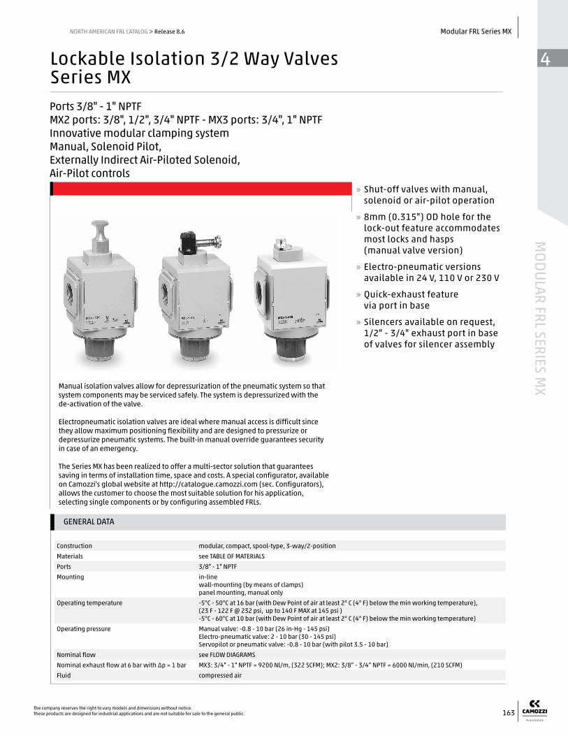
Lockable Isolation 3/2 Way ValvesSeries MXPorts 3/8" - 1" NPTFMX2 ports: 3/8", 1/2", 3/4" NPTF - MX3 ports: 3/4", 1" NPTF Innovative modular clamping system Manual, Solenoid Pilot, Externally Indirect Air-Piloted Solenoid, Air-Pilot controls
Manual isolation valves allow for depressurization of the pneumatic system so that system components may be serviced safely. The system is depressurized with the de-activation of the valve.
Electropneumatic isolation valves are ideal where manual access is difficult since they allow maximum positioning flexibility and are designed to pressurize or depressurize pneumatic systems. The built-in manual override guarantees security in case of an emergency.
The Series MX has been realized to offer a multi-sector solution that guarantees saving in terms of installation time, space and costs. A special configurator, available on Camozzi's global website at http://catalogue.camozzi.com (sec. Configurators), allows the customer to choose the most suitable solution for his application, selecting single components or by configuring assembled FRLs.
» Shut-off valves with manual, solenoid or air-pilot operation
» 8mm (0.315") OD hole for the lock-out feature accommodates most locks and hasps (manual valve version)
» Electro-pneumatic versions available in 24 V, 110 V or 230 V
» Quick-exhaust feature via port in base
» Silencers available on request, 1/2" - 3/4" exhaust port in base of valves for silencer assembly

44
MOD
ULAR
FRL
SER
IES
MX
164The company reserves the right to vary models and dimensions without notice.
These products are designed for industrial applications and are not suitable for sale to the general public.
Modular FRL Series MX NORTH AMERICAN FRL CATALOG >> Release 8.6
Lockable isolation 3/2 way valves Series MX - materials
PARTS MATERIALS
1 = Body Aluminium
2 = Covering Polyacetal
3 = Valve holder plug Polyacetal
4 = Lower spring Zinc-plated steel
5 = Spool Stainless steel (MX...V16 - V17 - V36)Aluminium (MX...V01)
Seals NBR
MX SERIES
2 SIZE:2 = 3/8” - 1/2” - 3/4”3 = 3/4” - 1”
3/8 PORT:3/8 = 3/81/2 = 1/23/4 = 3/41 = 1
V 3/2-WAY VALVE
01 DESIGN TYPE:01 = lockable manual control (lock-out design)16 = electro-pneumatic control (solenoid pilot-operated)17 = servo-pilot control (external air-signal pilot for solenoid w/ lower than 30 psi pressure supply)36 = pneumatic control (air-pilot operated)
FLOW DIRECTION: = from left to right (standard) LH = from right to left
TF TF = NPTF portsblank = BSP ports
CODING EXAMPLE
MX 2 - 3/8 - V 01 - __ TF
For the assembly of a single component with fixing flanges or wall-mounting, see the section “FRL Series MX Assembled”

Diagram for lockable manual control valvesΔP = Pressure dropQ = Flow
Inlet pressure2 bar = 29 psi4 bar = 58 psi6 bar = 87 psi8 bar = 116 psi
psi bar
14.5 1
11.6 0.8
8.7 0.6
5.8 0.4
2.9 0.2
00 2000 4000 6000 8000 10000 Q (Nl/min) 70 140 210 280 350 Air Flow (SCFM)
44
MODULAR FRL SERIES M
X
165The company reserves the right to vary models and dimensions without notice.These products are designed for industrial applications and are not suitable for sale to the general public.
Modular FRL Series MXNORTH AMERICAN FRL CATALOG >> Release 8.6
Diagram for lockable manual control valvesΔP = Pressure dropQ = Flow
FLOW DIAGRAM for valves Mod. MX...V01
Lockable (Lock-Out), manual valves Series MX - dimensions
DIMENSIONS (in inches)
Mod. AExhaust Port
B C F G I L M N O P Q R S SW TWeight
(kg)
MX2-3/8-V01-TF 3/8 G 1/2 2.756 0.709 1.358 2.677 0.354 0.315 5.984 0.512 2.008 1.220 3.465 2.500 1.063 1.476 0.5
MX2-1/2-V01-TF 1/2 G 1/2 2.756 0.709 1.358 2.677 0.354 0.315 5.984 0.512 2.008 1.220 3.465 2.500 1.063 1.476 0.5
MX2-3/4-V01-TF 3/4 G 1/2 2.756 0.709 1.358 2.677 0.354 0.315 5.984 0.512 2.008 1.220 3.465 2.500 1.063 1.476 0.5
MX3-3/4-V01-TF 3/4 G 3/4 3.524 0.906 1.890 2.992 0.315 0.315 8.091 1.457 2.618 1.575 4.016 3.720 1.339 1.752 0.9
MX3-1-V01-TF 1 G 3/4 3.524 0.906 1.890 2.992 0.315 0.315 8.091 1.457 2.618 1.575 4.016 3.720 1.339 1.752 0.9
Fig. 1 = closed valve, lock opening exposed, exhausting downstream pressureFig. 2 = open valve, “down” handle position, flow 1 to 2
Inlet pressure2 bar = 29 psi4 bar = 58 psi6 bar = 87 psi8 bar = 116 psi
psi bar
14.5 1
11.6 0.8
8.7 0.6
5.8 0.4
2.9 0.2
00 1000 2000 3000 4000 5000 Q (Nl/min) 35 70 105 140 175 Air Flow (SCFM)
MX2 flow curves MX3 flow curves

44
MOD
ULAR
FRL
SER
IES
MX
166The company reserves the right to vary models and dimensions without notice.
These products are designed for industrial applications and are not suitable for sale to the general public.
Modular FRL Series MX NORTH AMERICAN FRL CATALOG >> Release 8.6
Diagram for solenoid pilot or air-pilot valves MX2 Δp = Pressure dropQ = Flow
Diagram for solenoid pilot or air-pilot valves MX3 Δp = Pressure dropQ = Flow
FLOW DIAGRAM for valves Mod. MX...V16 and MX...V36
Solenoid pilot and air-pilot operated valves
3/2-way isolation valves Series MX - dimensions
DIMENSIONS (in inches)
Mod. AExhaust Port
B C G I N O P R S SW TPilot Port
YWeight
(Kg)
MX2-3/8-V16-TF 3/8 G 1/2 2.756 1.358 2.677 6.732 0.512 2.756 3.465 2.500 1.339 1.476 - 0.5
MX2-1/2-V16-TF 1/2 G 1/2 2.756 1.358 2.677 6.732 0.512 2.756 3.465 2.500 1.339 1.476 - 0.5
MX2-3/4-V16-TF 3/4 G 1/2 2.756 1.358 2.677 6.732 0.512 2.756 3.465 2.500 1.339 1.476 - 0.5
MX2-3/8-V36-TF 3/8 G 1/2 2.756 1.358 2.677 4.803 0.512 0.827 3.465 2.500 1.339 1.476 1/8 0.5
MX2-1/2-V36-TF 1/2 G 1/2 2.756 1.358 2.677 4.803 0.512 0.827 3.465 2.500 1.339 1.476 1/8 0.5
MX2-3/4-V36-TF 3/4 G 1/2 2.756 1.358 2.677 4.803 0.512 0.827 3.465 2.500 1.339 1.476 1/8 0.5
MX3-3/4-V16-TF 3/4 G 3/4 3.524 1.890 2.992 7.106 1.457 1.634 4.016 3.720 1.339 1.752 - 0.9
MX3-1-V16-TF 1 G 3/4 3.524 1.890 2.992 7.106 1.457 1.634 4.016 3.720 1.339 1.752 - 0.9
MX3-3/4-V36-TF 3/4 G 3/4 3.524 1.890 2.992 6.457 1.457 1.004 4.016 3.720 1.339 1.752 1/8 0.9
MX3-1-V36-TF 1 G 3/4 3.524 1.890 2.992 6.457 1.457 1.004 4.016 3.720 1.339 1.752 1/8 0.9
psi bar
14.5 1
11.6 0.8
8.7 0.6
5.8 0.4
2.9 0.2
0
psi bar
14.5 1
11.6 0.8
8.7 0.6
5.8 0.4
2.9 0.2
00 2000 4000 6000 8000 10000 Q (Nl/min) 70 140 210 280 350 Air Flow (SCFM)
0 1000 2000 3000 4000 5000 Q (Nl/min) 35 70 105 140 175 Air Flow (SCFM)
MX2 flow curves MX3 flow curves
EV10 = solenoid valve, 3/2 NC, monostable, with bistable manual override
YES1 = pneumatically operated valve, 3/2, monostable, mechanical spring

44
MODULAR FRL SERIES M
X
167The company reserves the right to vary models and dimensions without notice.These products are designed for industrial applications and are not suitable for sale to the general public.
Modular FRL Series MXNORTH AMERICAN FRL CATALOG >> Release 8.6
DIMENSIONS (in inches)
Mod. AExhaust Port
B C G I N O P R S SW T XWeight
(Kg)
MX2-3/8-V17-TF 3/8 G 1/2 2.756 1.358 2.677 6.732 0.512 2.756 3.465 2.500 1.339 1.476 M5 0.5
MX2-1/2-V17-TF 1/2 G 1/2 2.756 1.358 2.677 6.732 0.512 2.756 3.465 2.500 1.339 1.476 M5 0.5
MX2-3/4-V17-TF 3/4 G 1/2 2.756 1.358 2.677 6.732 0.512 2.756 3.465 2.500 1.339 1.476 M5 0.5
MX3-3/4-V17-TF 3/4 G 3/4 3.524 1.890 2.992 7.106 1.457 1.634 4.016 3.720 1.339 1.752 M5 0.9
MX3-1-V17-TF 1 G 3/4 3.524 1.890 2.992 7.106 1.457 1.634 4.016 3.720 1.339 1.752 M5 0.9
Diagram for servo-pilot control valves MX2 Δp = Pressure dropQ = Flow
Diagram for servo-pilot control valves MX3 Δp = Pressure dropQ = Flow
FLOW DIAGRAM for valves Mod. MX...V17
External air-pilot, solenoid operated (for operating line pressures below 30 psi; min. pilot pressure 30 psi) valves
EV11 = solenoid valve, 3/2, monostable, solenoid pilot with separate air supply and bistable manual override
3/2-way isolation valves Series MX - dimensions
psi bar
14.5 1
11.6 0.8
8.7 0.6
5.8 0.4
2.9 0.2
00 2000 4000 6000 8000 10000 Q (Nl/min) 70 140 210 280 350 Air Flow (SCFM)
psi bar
14.5 1
11.6 0.8
8.7 0.6
5.8 0.4
2.9 0.2
00 1000 2000 3000 4000 5000 Q (Nl/min) 35 70 105 140 175 Air Flow (SCFM)
MX2 flow curves MX3 flow curves

GENERAL DATA
Construction modular, compact, poppet-typeMaterials see TABLE OF MATERIALSPorts 3/8" - 1" NPTFMounting in-line
wall-mounting (by means of clamps)Operating temperature -5°C - 50°C at 16 bar with Dew Point of air at least 2° C (4° F) below the min working temperature,
(23 F - 122 F @ 232 psi, up to 140 F MAX at 145 psi )-5°C - 60°C at 10 bar with Dew Point of air at least 2° C (4° F) below the min working temperature
Operating pressure 2 - 16 bar (30 - 232 psi)Nominal flow (at 6 bar with ∆P 1 bar) MX3: 8500 l/min, (298 SCFM) , MX2: 5800 Nl/min, 203 SCFM (1/2” , 3/4”)
MX2: 4500 Nl/min, 157 SCFM (3/8”)Fluid compressed air
44
MOD
ULAR
FRL
SER
IES
MX
168The company reserves the right to vary models and dimensions without notice.
These products are designed for industrial applications and are not suitable for sale to the general public.
Modular FRL Series MX NORTH AMERICAN FRL CATALOG >> Release 8.6
Soft Start ValvesSeries MXPorts 3/8" - 1" NPTFMX2 ports: 3/8”, 1/2”, 3/4” NPTF - MX3 ports: 3/4”, 1” NPTF Modular
These soft start valves allow a gradual increase of the pressure in pneumatic systems. The pressure increases slowly according to the screw-adjustable regulation until it reaches half of the set value, then it increases rapidly. The valve poppet shifts slowly and securely to the open position to prevent sudden and unsafe movements of the pneumatic components in the system.
The Series MX has been realized to offer a multi-sector solution that guarantees saving in terms of installation time, space and costs. A special configurator, available on Camozzi's global website at http://catalogue.camozzi.com (sec. Configurators), allows the customer to choose the most suitable solution for his application, selecting single components or by configuring assembled FRLs.
» Allow for a safe, gradual pressurization of the pneumatic system from start-up
» Screw adjustment of the timing delay which regulates inlet pressure to 50% of its value before full pressurization
» Optional pressure switches are available on request

44
MODULAR FRL SERIES M
X
169The company reserves the right to vary models and dimensions without notice.These products are designed for industrial applications and are not suitable for sale to the general public.
Modular FRL Series MXNORTH AMERICAN FRL CATALOG >> Release 8.6
For the assembly of a single component with fixing flanges or wall-mounting, see the section “FRL Series MX Assembled”
Soft start valves Series MX - materials
PARTS MATERIALS
1 = Body Aluminium
2 = Covering Polyacetal
3 = Valve holder plug Polyacetal
4 = Lower spring Stainless steel
Seals NBR
MX SERIES
2 SIZE:2 = 3/8” - 1/2” - 3/4”3 = 3/4” - 1”
3/8 PORT:3/8 = 3/81/2 = 1/23/4 = 3/4 1 = 1
AV SOFT START VALVE
FLOW DIRECTION: = from left to right (standard) LH = from right to left
TF TF = NPTF portsblank = BSP ports
CODING EXAMPLE
MX 2 - 3/8 - AV - __ TF

44
MOD
ULAR
FRL
SER
IES
MX
170The company reserves the right to vary models and dimensions without notice.
These products are designed for industrial applications and are not suitable for sale to the general public.
Modular FRL Series MX NORTH AMERICAN FRL CATALOG >> Release 8.6
MX2 DIAGRAMS FOR PRESSURISATION TIMES
Pressurisation times as to the number of turns of the regulation screw, with downstream volume of 5 litres. A = 5 turns - B = 4 turns - C = 3 turns - D = 2 turns - E = 1 turn. K = number of turns of the regulation screw required to obtain the required pressurisation time with an inlet pressure of 6 bar. Variations of the inlet pressure can cause deviations of the pressure time by ± 20%. K = t/V where: V = volume of the downstream system in litres; t = desired pressuring time in seconds.
EXAMPLE:V = 5 litrest = 16 secondsK = 16/5 = 3,2
Using in the graph this value K, the number of turns of the regulation screw will be approx. 0,8.
Pressurisation times as to the number of turns of the regulation screw, with downstream volume of 5 litres. A = 5 turns - B = 4 turns - C = 3 turns - D = 2 turns - E = 1 turn. K = number of turns of the regulation screw required to obtain the required pressurisation time with an inlet pressure of 6 bar. Variations of the inlet pressure can cause deviations of the pressure time by ± 20%. K = t/V where: V = volume of the downstream system in litres; t = desired pressuring time in seconds.
EXAMPLE:V = 5 litrest = 16 secondsK = 16/5 = 3,2
Using in the graph this value K, the number of turns of the regulation screw will be approx. 1,8.
MX3 DIAGRAMS FOR PRESSURISATION TIMES
Turns
Inlet Pressure
TurnsInlet Pressure

44
MODULAR FRL SERIES M
X
171The company reserves the right to vary models and dimensions without notice.These products are designed for industrial applications and are not suitable for sale to the general public.
Modular FRL Series MXNORTH AMERICAN FRL CATALOG >> Release 8.6
Soft start valves Series MX - dimensions
DIMENSIONS (in inches)
Mod. A
Pressure Sensor Port
B C G I M R S T Weight (Kg)
MX2-3/8-AV-TF 3/8 G 1/8 2.756 2.559 2.677 1.831 3.465 1.988 1.476 0.4
MX2-1/2-AV-TF 1/2 G 1/8 2.756 2.559 2.677 1.831 3.465 1.988 1.476 0.4
MX2-3/4-AV-TF 3/4 G 1/8 2.756 2.559 2.677 1.831 3.465 1.988 1.476 0.4
MX3-3/4-AV-TF 3/4 G 1/8 3.524 2.953 2.992 1.890 4.016 2.264 1.752 0.7
MX3-1-AV-TF 1 G 1/8 3.524 2.953 2.992 1.890 4.016 2.264 1.752 0.7
GENERAL DATA
Construction modular, compact, diaphragm-typeMaterials see TABLE OF MATERIALSPorts MX2: 1/2” NPTF , MX3: 1” NPTFTake-off ports MX2: 1/2” NPTF , MX3: 1” NPTFMounting in-line
wall-mounting (by means of clamps)Operating temperature -5°C - 50°C at 16 bar with Dew Point of air at least 2° C (4° F) below the min working temperature,
(23 F - 122 F @ 232 psi, up to 140 F MAX at 145 psi )-5°C - 60°C at 10 bar with Dew Point of air at least 2° C (4° F) below the min working temperature
Operating pressure 0 - 16 bar, (0 - 232 psi)Nominal flow at 6 bar with ∆p = 1 bar MX2-1/2-B00 = 6800 Nl/m, (238 SCFM)
MX2-1/2-B01 = 5700 Nl/m, (200 SCFM)MX3-1-B00 = 14500 Nl/m, (507 SCFM)MX3-1-B01 = 10500 Nl/m, (367 SCFM)
Fluid compressed air
44
MOD
ULAR
FRL
SER
IES
MX
172The company reserves the right to vary models and dimensions without notice.
These products are designed for industrial applications and are not suitable for sale to the general public.
Modular FRL Series MX NORTH AMERICAN FRL CATALOG >> Release 8.6
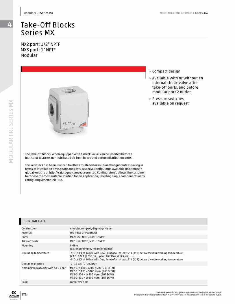
Take-Off BlocksSeries MXMX2 port: 1/2" NPTFMX3 port: 1" NPTF Modular
The Take-off blocks, when equipped with a check-valve, can be inserted before a lubricator to access non-lubricated air from its top and bottom distribution ports.
The Series MX has been realized to offer a multi-sector solution that guarantees saving in terms of installation time, space and costs. A special configurator, available on Camozzi's global website at http://catalogue.camozzi.com (sec. Configurators), allows the customer to choose the most suitable solution for his application, selecting single components or by configuring assembled FRLs.
» Compact design
» Available with or without an internal check-valve after take-off ports, and before modular port 2 outlet
» Pressure switches available on request
44
MODULAR FRL SERIES M
X
173The company reserves the right to vary models and dimensions without notice.These products are designed for industrial applications and are not suitable for sale to the general public.
Modular FRL Series MXNORTH AMERICAN FRL CATALOG >> Release 8.6
For the assembly of a single component with fixing flanges or wall-mounting, see the section “FRL Series MX Assembled”
Take-off blocks Series MX - materials
PARTS MATERIALS
1 = Body Aluminium
2 = Covering Polyacetal
Seals NBR
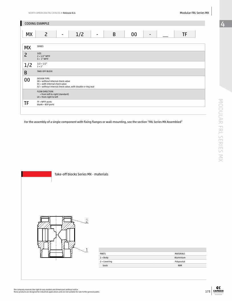
MX SERIES
2 SIZE:2 = 1/2” NPTF3 = 1” NPTF
1/2 1/2 = 1/2”1 = 1”
B TAKE-OFF BLOCK
00 DESIGN TYPE:00 = without internal check valve01 = with internal check valve 02 = without internal check valve, with double o-ring seat
FLOW DIRECTION: = from left to right (standard) LH = from right to left
TF TF = NPTF portsblank = BSP ports
CODING EXAMPLE
MX 2 - 1/2 - B 00 - __ TF

44
MOD
ULAR
FRL
SER
IES
MX
174The company reserves the right to vary models and dimensions without notice.
These products are designed for industrial applications and are not suitable for sale to the general public.
Modular FRL Series MX NORTH AMERICAN FRL CATALOG >> Release 8.6
Take-off blocks Series MX - dimensions
DIMENSIONS (in inches)
Mod. A B C G I R S T Weight (Kg)
MX2-1/2-B00-TF 1/2 1/2 2.756 2.559 2.677 3.386 1.870 1.516 0.4
MX3-1-B00-TF 1 1 3.524 2.953 2.992 3.898 2.146 1.752 0.6
BL01 = take-off block
BL02 = take-off block with VNR
The take-off block with double O-ring seat is particularly suitable when Series MX modules have to be supplied through the same pressure source. The modules which are connected to the left side are of LH kind.
Use of the take-off block MX...- B02

GENERAL DATA
Construction modular, compactMaterials see catalogue pages referring to the single componentPorts 3/8" - 1" NPTFMounting vertical in-line
wall-mounting (by means of direct screws or bracket mounts)panel mounting
Operating temperature -5°C - 50°C at 16 bar (according to the single component characteristics)-5°C - 60°C at 10 bar (according to the single component characteristics)
44
MODULAR FRL SERIES M
X
175The company reserves the right to vary models and dimensions without notice.These products are designed for industrial applications and are not suitable for sale to the general public.
Modular FRL Series MXNORTH AMERICAN FRL CATALOG >> Release 8.6
FRL Series MX Pre-Assembled(single part number codes, fully assembled)
Ports 3/8" - 1" NPTFMX2 ports: 3/8”, 1/2”, 3/4” NPTF; MX3 ports: 3/4”, 1” NPTF Assembly can be specified with either standard modular brackets and/or integrated wall-mount brackets
The new FRL Series MX can be easily assembled through rapid clamps which allow the connection among single components creating an unlimited number of combinations.The FRL groups Series MX are also available in the already mounted version (with a single code).
The use of three different types of rapid clamps (standard, with wall mounting screws or with wall-mount brackets) allows an easy mounting of the assembled groups and to carry out maintenance operations on the single components with no need to disassemble the group.
» Compact design
» Simple modularity
» Great reliability and performance
» Easy and quick maintenance
» Reduced weight

44
MOD
ULAR
FRL
SER
IES
MX
176The company reserves the right to vary models and dimensions without notice.
These products are designed for industrial applications and are not suitable for sale to the general public.
Modular FRL Series MX NORTH AMERICAN FRL CATALOG >> Release 8.6
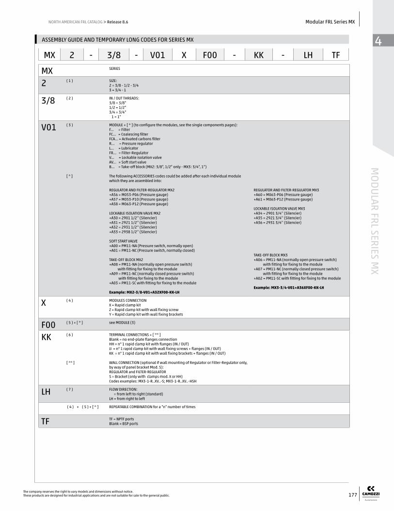
Configuration of the assembled group in the drawing below:MX2-3/8-V01+A32XF00XR004YL00XV16-KK
ASSEMBLY GUIDE AND TEMPORARY LONG CODES FOR SERIES MX
Numbers in above position boxes refer to positions called out on next page in the Code Key. Each number is called out in order of the components' thread size and assembly order, including bracket choices.
Position 1 is for general family body size (in this case, 2)Position 2 is for thread port size options (in this case, 3/8" ports)Position 3 is the first component (in this case, a “…-V01” lock-out valve with a 2931 1/2 silencer accessory)Positions 4 & 5 will continue to repeat for each additional component and the bracket that typically comes before itPosition 6 is final outer edge bracket choices, with or without flange units Position 7 is only for optional right-to-left assembly/flow diagram requests
Positions 3 & 5 will require in most cases that the entire callout of the module be assembled with its unique features (such as the above regulator called out as “R004”)
Positions 4 & 6, outer brackets and intermediate brackets, utilize the same abbreviated letters for bracket styles, EXCEPT if wall-mount flanges are desired (see Code Key place “6” for options - ‘HH’ ‘JJ’ and ‘KK’ for the end bracket sets to include the wall flange kits)
44
MODULAR FRL SERIES M
X
177The company reserves the right to vary models and dimensions without notice.These products are designed for industrial applications and are not suitable for sale to the general public.
Modular FRL Series MXNORTH AMERICAN FRL CATALOG >> Release 8.6
MX SERIES
2 ( 1 ) SIZE:2 = 3/8 - 1/2 - 3/43 = 3/4 - 1
3/8 ( 2 ) IN / OUT THREADS:3/8 = 3/8”1/2 = 1/2”3/4 = 3/4” 1 = 1”
V01 ( 3 )
[ * ]
MODULE + [ * ] (to configure the modules, see the single components pages):F... = FilterFC... = Coalescing filterFCA... = Activated carbons filterR... = Pressure regulatorL... = LubricatorFR... = Filter-RegulatorV... = Lockable isolation valveAV... = Soft start valveB... = Take-off block (MX2: 3/8”, 1/2” only - MX3: 3/4”, 1”)
The following ACCESSORIES codes could be added after each individual module which they are assembled into:
REGULATOR AND FILTER-REGULATOR MX2+A56 = M053-P06 (Pressure gauge)+A57 = M053-P10 (Pressure gauge)+A58 = M063-P12 (Pressure gauge)
LOCKABLE ISOLATION VALVE MX2+A30 = 2901 1/2’’ (Silencier)+A31 = 2921 1/2’’ (Silencier)+A32 = 2931 1/2’’ (Silencier)+A33 = 2938 1/2’’ (Silencier)
SOFT START VALVE+A00 = PM11-NA (Pressure switch, normally open)+A01 = PM11-NC (Pressure switch, normally closed)
TAKE-OFF BLOCK MX2+A08 = PM11-NA (normally open pressure switch) with fitting for fixing to the module+A09 = PM11-NC (normally closed pressure switch) with fitting for fixing to the module+A03 = PM11-SC with fitting for fixing to the module
Example: MX2-3/8-V01+A32XF00-KK-LH
REGULATOR AND FILTER-REGULATOR MX3+A60 = M063-P06 (Pressure gauge)+A61 = M063-P12 (Pressure gauge) LOCKABLE ISOLATION VALVE MX3+A34 = 2901 3/4’’ (Silencier)+A35 = 2921 3/4’’ (Silencier)+A36 = 2931 3/4’’ (Silencier)
TAKE-OFF BLOCK MX3+A06 = PM11-NA (normally open pressure switch) with fitting for fixing to the module+A07 = PM11-NC (normally closed pressure switch) with fitting for fixing to the module+A02 = PM11-SC with fitting for fixing to the module
Example: MX3-3/4-V01+A36XF00-KK-LH
X ( 4 ) MODULES CONNECTIONX = Rapid clamp kitZ = Rapid clamp kit with wall fixing screwY = Rapid clamp kit with wall fixing brackets
F00 ( 5 ) + [ * ] see MODULE (3)
KK ( 6 )
[ ** ]
TERMINAL CONNECTIONS + [ ** ]Blank = no end-plate flanges connectionHH = n° 1 rapid clamp kit with flanges (IN / OUT)JJ = n° 1 rapid clamp kit with wall fixing screws + flanges (IN / OUT)KK = n° 1 rapid clamp kit with wall fixing brackets + flanges (IN / OUT)
WALL CONNECTION (optional if wall mounting of Regulator or Filter-Regulator only, by way of panel bracket Mod. S):REGULATOR and FILTER-REGULATORS = Bracket (only with clamps mod. X or HH)Codes examples: MX3-1-R..XV..-S; MX3-1-R..XV..-HSH
LH ( 7 ) FLOW DIRECTION: = from left to right (standard)LH = from right to left
( 4 ) + ( 5 ) + [ * ] REPEATABLE COMBINATION for a “n” number of times
TF TF = NPTF ports Blank = BSP ports
ASSEMBLY GUIDE AND TEMPORARY LONG CODES FOR SERIES MX
MX 2 - 3/8 - V01 X F00 - KK - LH TF

44
MOD
ULAR
FRL
SER
IES
MX
178The company reserves the right to vary models and dimensions without notice.
These products are designed for industrial applications and are not suitable for sale to the general public.
Modular FRL Series MX NORTH AMERICAN FRL CATALOG >> Release 8.6
Wall mounting dimensions and positioning scheme
Legend of the POSITIONING SCHEME:1 = rapid clamp with wall fixing screw or with wall fixing bracket2 = module / flange
* POSITIONING SCHEME referring todrawings “ Y “ and “ Z “.
Legend of the ASSEMBLED GROUPS DRAWINGS:“ Y “ = with rapid clamps with wall fixing brackets (MX...-Y)“ Z “ = with rapid clamp with wall fixing screws (MX...-Z) G = wall mount screw hole
Dimensions in millimeters (mm)
Mod. A B C D F1 F2 L M
MX2-Y 210 140 68,5 134,5 70 37 - -
MX2-Z 210 140 23 - 37,5 37 13,5 M5
MX3-Y 267 178 82 160 68 40,5 - -
MX3-Z 267 178 27 - 40,5 40,5 13 M6
Temporary Assembly Guide: Ex.: MX3-3/4-V01XF00XR004YL00XV16-KK TF
Notes: 3/4" NPTF unit, w/o silencers or switch accessories. Utilizing wall-mount brackets and flange end-plates
Temporary Assembly Guide Ex.: MX3-1-V01XF00ZR004ZL00XV16-HH TF
Notes: 1" NPTF unit, w/o silencers or switch accessories. Utilizing only rapid mounting clamps, wall screwsand flange end-plates.
44
MODULAR FRL SERIES M
X
179The company reserves the right to vary models and dimensions without notice.These products are designed for industrial applications and are not suitable for sale to the general public.
Modular FRL Series MXNORTH AMERICAN FRL CATALOG >> Release 8.6
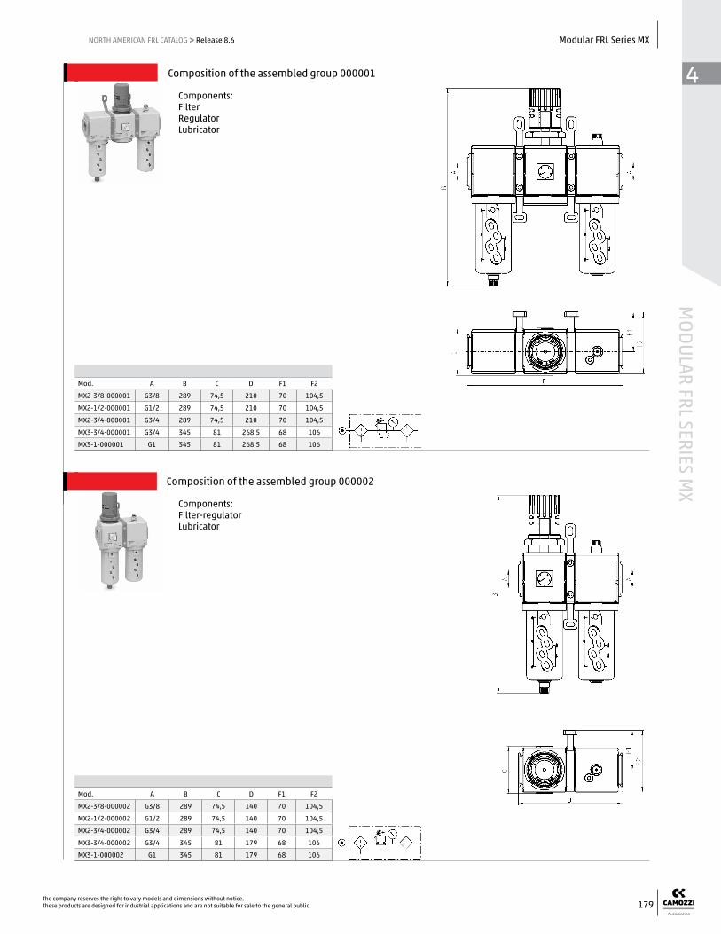
Composition of the assembled group 000001
Components: Filter Regulator Lubricator
Mod. A B C D F1 F2
MX2-3/8-000001 G3/8 289 74,5 210 70 104,5
MX2-1/2-000001 G1/2 289 74,5 210 70 104,5
MX2-3/4-000001 G3/4 289 74,5 210 70 104,5
MX3-3/4-000001 G3/4 345 81 268,5 68 106
MX3-1-000001 G1 345 81 268,5 68 106
Composition of the assembled group 000002
Components: Filter-regulator Lubricator
Mod. A B C D F1 F2
MX2-3/8-000002 G3/8 289 74,5 140 70 104,5
MX2-1/2-000002 G1/2 289 74,5 140 70 104,5
MX2-3/4-000002 G3/4 289 74,5 140 70 104,5
MX3-3/4-000002 G3/4 345 81 179 68 106
MX3-1-000002 G1 345 81 179 68 106

44
MOD
ULAR
FRL
SER
IES
MX
180The company reserves the right to vary models and dimensions without notice.
These products are designed for industrial applications and are not suitable for sale to the general public.
Modular FRL Series MX NORTH AMERICAN FRL CATALOG >> Release 8.6
Composition of the assembled group 000003
Components: Lockable isolation 3/2-way valve Filter-regulator Lubricator
Mod. A B C D F1 F2
MX2-3/8-000003 G3/8 289 74,5 210 70 104,5
MX2-1/2-000003 G1/2 289 74,5 210 70 104,5
MX2-3/4-000003 G3/4 289 74,5 210 70 104,5
MX3-3/4-000003 G3/4 345 81 268,5 68 106
MX3-1-000003 G1 345 81 268,5 68 106
Composition of the assembled group 000004
Components: Lockable isolation 3/2-way valve Filter-regulator
Mod. A B C D F1 F2
MX2-3/8-000004 G3/8 289 74,5 140 70 104,5
MX2-1/2-000004 G1/2 289 74,5 140 70 104,5
MX2-3/4-000004 G3/4 289 74,5 140 70 104,5
MX3-3/4-000004 G3/4 345 81 179 68 106
MX3-1-000004 G1 345 81 179 68 106

44
MODULAR FRL SERIES M
X
181The company reserves the right to vary models and dimensions without notice.These products are designed for industrial applications and are not suitable for sale to the general public.
Modular FRL Series MXNORTH AMERICAN FRL CATALOG >> Release 8.6
Composition of the assembled group 000005
Components: Filter-regulator Lockable isolation 3/2-way valve Soft start valve
Mod. A B C D F1 F2
MX2-3/8-000005 G3/8 289 74,5 210 70 104,5
MX2-1/2-000005 G1/2 289 74,5 210 70 104,5
MX2-3/4-000005 G3/4 289 74,5 210 70 104,5
MX3-3/4-000005 G3/4 345 81 268,5 68 106
MX3-1-000005 G1 345 81 268,5 68 106
Composition of the assembled group 000006
Components: Filter-regulator Lubricator Lockable isolation 3/2-way valve Soft start valve
Mod. A B C D F1 F2
MX2-3/8-000006 G3/8 289 74,5 280 70 104,5
MX2-1/2-000006 G1/2 289 74,5 280 70 104,5
MX2-3/4-000006 G3/4 289 74,5 280 70 104,5
MX3-3/4-000006 G3/4 345 81 358 68 106
MX3-1-000006 G1 345 81 358 68 106

44
MOD
ULAR
FRL
SER
IES
MX
182The company reserves the right to vary models and dimensions without notice.
These products are designed for industrial applications and are not suitable for sale to the general public.
Modular FRL Series MX NORTH AMERICAN FRL CATALOG >> Release 8.6
Composition of the assembled group 000007
Components: Lockable isolation 3/2-way valve Filter-regulator Lockable isolation 3/2-way valve Soft start valve
Mod. A B C D F1 F2
MX2-3/8-000007 G3/8 289 74,5 280 70 104,5
MX2-1/2-000007 G1/2 289 74,5 280 70 104,5
MX2-3/4-000007 G3/4 289 74,5 280 70 104,5
MX3-3/4-000007 G3/4 345 81 358 68 106
MX3-1-000007 G1 345 81 358 68 106
Composition of the assembled group 000008
Components: Lockable isolation 3/2-way valve Filter-regulator Lubricator Lockable isolation 3/2-way valve Soft start valve + pressure switch (NO)
Mod. A B C D F1 F2
MX2-3/8-000008 G3/8 289 74,5 350 70 104,5
MX2-1/2-000008 G1/2 289 74,5 350 70 104,5
MX2-3/4-000008 G3/4 289 74,5 350 70 104,5
MX3-3/4-000008 G3/4 345 81 447,5 68 106
MX3-1-000008 G1 345 81 447,5 68 106

44
MODULAR FRL SERIES M
X
183The company reserves the right to vary models and dimensions without notice.These products are designed for industrial applications and are not suitable for sale to the general public.
Modular FRL Series MXNORTH AMERICAN FRL CATALOG >> Release 8.6
Composition of the assembled group 000009
Components: Lockable isolation 3/2-way valve Filter-regulator Lubricator Lockable isolation 3/2-way valve Soft start valve + pressure switch (NC)
Mod. A B C D F1 F2
MX2-3/8-000009 G3/8 289 74,5 350 70 104,5
MX2-1/2-000009 G1/2 289 74,5 350 70 104,5
MX2-3/4-000009 G3/4 289 74,5 350 70 104,5
MX3-3/4-000009 G3/4 345 81 447,5 68 106
MX3-1-000009 G1 345 81 447,5 68 106
Composition of the assembled group 000010
Components: Lockable isolation 3/2-way valve Filter-regulator Lockable isolation 3/2-way valve Soft start valve + pressure switch (NO)
Mod. A B C D F1 F2
MX2-3/8-000010 G3/8 289 74,5 280 70 104,5
MX2-1/2-000010 G1/2 289 74,5 280 70 104,5
MX2-3/4-000010 G3/4 289 74,5 280 70 104,5
MX3-3/4-000010 G3/4 345 81 358 68 106
MX3-1-000010 G1 345 81 358 68 106

44
MOD
ULAR
FRL
SER
IES
MX
184The company reserves the right to vary models and dimensions without notice.
These products are designed for industrial applications and are not suitable for sale to the general public.
Modular FRL Series MX NORTH AMERICAN FRL CATALOG >> Release 8.6
Composition of the assembled group 000011
Components: Lockable isolation 3/2-way valve Filter-regulator Lockable isolation 3/2-way valve Soft start valve + pressure switch (NC)
Mod. A B C D F1 F2
MX2-3/8-000011 G3/8 289 74,5 280 70 104,5
MX2-1/2-000011 G1/2 289 74,5 280 70 104,5
MX2-3/4-000011 G3/4 289 74,5 280 70 104,5
MX3-3/4-000011 G3/4 345 81 358 68 106
MX3-1-000011 G1 345 81 358 68 106
Composition of the assembled group 000012
Components: Filter Coalescing filter
Mod. A B C D F1 F2
MX2-3/8-000012 G3/8 210 72 140 70 104,5
MX2-1/2-000012 G1/2 210 72 140 70 104,5
MX2-3/4-000012 G3/4 210 72 140 70 104,5
MX3-3/4-000012 G3/4 231 78 179 68 106
MX3-1-000012 G1 231 78 179 68 106

44
MODULAR FRL SERIES M
X
185The company reserves the right to vary models and dimensions without notice.These products are designed for industrial applications and are not suitable for sale to the general public.
Modular FRL Series MXNORTH AMERICAN FRL CATALOG >> Release 8.6
ACCESSORIES FOR SERIES MX
Rapid clamps Rapid clamps with brackets
Terminal flanges (IN/OUT)
Fixing brackets for regulators
Block for pressure gauge fixing
Assembly O-ring MX built-in pressure gauge
Systems of rapid connections designed to make mounting easier.
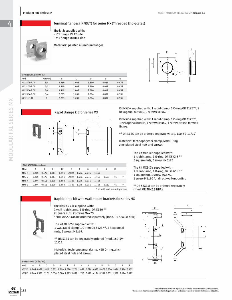
44
MOD
ULAR
FRL
SER
IES
MX
186The company reserves the right to vary models and dimensions without notice.
These products are designed for industrial applications and are not suitable for sale to the general public.
Modular FRL Series MX NORTH AMERICAN FRL CATALOG >> Release 8.6
Terminal flanges (IN/OUT) for series MX (Threaded End-plates)
The kit is supplied with:- n°1 flange INLET side- n°1 flange OUTLET side
Materials: painted aluminum flanges
DIMENSIONS (in inches)
Mod. A (NPTF) B C D E G
MX2-3/8-FL-TF 3/8 1.969 1.043 2.500 0.669 0.433
MX2-1/2-FL-TF 1/2 1.969 1.043 2.500 0.669 0.433
MX2-3/4-FL-TF 3/4 1.969 1.043 2.500 0.669 0.433
MX3-3/4-FL-TF 3/4 2.283 1.201 2.874 0.807 0.531
MX3-1-FL-TF 1 2.283 1.201 2.874 0.807 0.531
Rapid clamps kit for series MX
The kit MX3-X is supplied with: 1 rapid clamp, 1 O-ring, OR 38X2.8 **2 square nuts, 2 screws M6x75
The kit MX3-Z is supplied with: 1 rapid clamp, 1 O-ring, OR 38X2.8 **1 square nut, 1 screw M6x75, 1 screw M6x90 for direct wall-mounting
**OR 38X2.8 can be ordered separately (mod. OR 38X2.8 NBR)
DIMENSIONS (in inches)
Mod. A B C D E F G H L M
MX2-X 0.205 0.472 1.811 0.551 2.894 1.476 2.776 1.457 -
MX2-Z 0.205 0.472 1.811 0.551 2.894 1.476 2.776 1.457 0.551 M5 *
MX3-X 0.244 0.551 2.126 0.650 3.386 1.575 3.031 1.713 -
MX3-Z 0.244 0.551 2.126 0.650 3.386 1.575 3.031 1.713 0.512 M6 *
Rapid clamp kit with wall mount brackets for series MX
The kit MX3-Y is supplied with:1 wall rapid clamp, 1 O-ring, OR 3150 **2 square nuts, 2 screws M6x75**OR 38X2.8 can be ordered separately (mod. OR 38X2.8 NBR)
DIMENSIONS (in inches)
Mod. A B C D E F G H I L M N O P R
MX2-Y 0.205 0.472 1.811 0.551 2.894 1.280 2.776 1.457 2.776 4.055 0.472 0.256 1.654 5.984 0.157
MX3-Y 0.244 0.551 2.126 0.650 3.386 1.575 3.031 1.713 2.677 4.134 0.591 0.331 1.988 7.126 0.177
* kit with wall mounting screw
The kit MX2-Y is supplied with:1 wall rapid clamp, 1 O-ring OR 3125 **, 2 hexagonal nuts, 2 screws M5x69.
** OR 3125 can be separately ordered (mod. 160-39-11/19)
Materials: technopolymer clamp, NBR O-ring, zinc-plated steel nuts and screws.
Kit MX2-X supplied with: 1 rapid clamp, 1 O-ring OR 3125**, 2 hexagonal nuts M5, 2 screws M5x69.
Kit MX2-Z supplied with: 1 rapid clamp, 1 O-ring OR 3125**, 1 hexagonal nut M5, 1 screw M5x69, 1 screw M5x85 for wall fixing.
** OR 3125 can be ordered separately (cod. 160-39-11/19)
Materials: technopolymer clamp, NBR O-ring,zinc-plated steel nuts and screws.

44
MODULAR FRL SERIES M
X
187The company reserves the right to vary models and dimensions without notice.These products are designed for industrial applications and are not suitable for sale to the general public.
Modular FRL Series MXNORTH AMERICAN FRL CATALOG >> Release 8.6
Assembly brackets and flange kit for series MX
Wall-mount brackets and flange kit for series MX
Single wall-mount bracket for regulator or filter-regulator series MX
Mod. A B C D E F G H L M N
MX2-S Ø 1.858 2.874 2.382 R 1.161 2.126 0.984 0.591 Ø 0.244 3.543 0.098 0.098
MX3-S Ø 2.252 3.346 2.185 R 1.358 2.598 1.181 0.591 Ø 0.323 3.543 0.098 0.098
DIMENSIONS (in millimeters)
The kit is supplied with 1 zinc-plated steel bracket
Mod. The kit is supplied with:
MX2-3/8-HH-TF 1x MX2-3/8-FL-TF + 2x MX2-X
MX2-1/2-HH-TF 1x MX2-1/2-FL-TF + 2x MX2-X
MX2-3/4-HH-TF 1x MX2-3/4-FL-TF + 2x MX2-X
MX2-3/8-JJ-TF 1x MX2-3/8-FL-TF + 2x MX2-Z
MX2-1/2-JJ-TF 1x MX2-1/2-FL-TF + 2x MX2-Z
MX2-3/4-JJ-TF 1x MX2-3/4-FL-TF + 2x MX2-Z
MX3-3/4-HH-TF 1x MX3-3/4-FL-TF + 2x MX3-X
MX3-1-HH-TF 1x MX3-1-FL-TF + 2x MX3-X
MX3-3/4-JJ-TF 1x MX3-3/4-FL-TF + 2x MX3-Z
MX3-1-JJ-TF 1x MX3-1-FL-TF + 2x MX3-Z
Mod. The kit is supplied with:
MX2-3/8-KK-TF 1x MX2-3/8-FL-TF + 2x MX2-Y
MX2-1/2-KK-TF 1x MX2-1/2-FL-TF + 2x MX2-Y
MX2-3/4-KK-TF 1x MX2-3/4-FL-TF + 2x MX2-Y
MX3-3/4-KK-TF 1x MX3-3/4-FL-TF + 2x MX3-Y
MX3-1-KK-TF 1x MX3-1-FL-TF + 2x MX3-Y

Mod. Range
MX3-R30/W-P 0-2.5 bar (0-36 psi)
MX3-R31/W-P 0-6 bar (0-87 psi)
MX3-R32/W-P 0-10 bar (0-145 psi)
MX3-R33/W-P 0-12 bar (0-174 psi)
Fig. 1 = pressure gauge Fig. 2 = seat
44
MOD
ULAR
FRL
SER
IES
MX
188The company reserves the right to vary models and dimensions without notice.
These products are designed for industrial applications and are not suitable for sale to the general public.
Modular FRL Series MX NORTH AMERICAN FRL CATALOG >> Release 8.6
O-ring for assembling Series MC - MX
Mod. O-ring For assembly between units and/or end-plates *
458-33/1 OR 2068 MC104 *
80-26-11/4T OR 3100 MC238 - MC202 *
160-39-11/19 OR 3125 MX2 *
OR 38X2.8 NBR OR 38X2.8 MX3 ** spare parts only
Threaded block for mounting external gauge
The kit is supplied with: 1 block 1 plug 2 screws 1 seal
DIMENSIONS
Mod. A B L M P U SW
MX2-R26/1-P 28 28 16.5 5 M3X7 1/8 5
MX3-R26/1-P 28 28 16.5 5 M3X7 1/4 6
MX Built-in pressure gauge
The kit is supplied with: 1 gauge 2 screws 1 seal
Top Related