


Languages
Pages
Legal


BENTLEY-HURNTV-KIT783
Select Bentley head-unit replacement kit
NTV-DOC272 JH (rev 1.1)
DO NOT ATTEMPT TO FIT THE BENTLEY-HUR UNTIL YOU HAVE
READ THE INSTALL MANUAL
3950 NW 120th Ave, Coral Springs, FL 33065 TEL 561-955-9770 FAX 561-955-9760
Overview
Kit Content
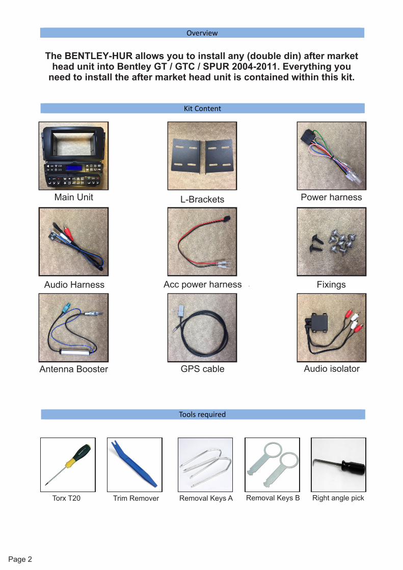
The BENTLEY-HUR allows you to install any (double din) after market head unit into Bentley GT / GTC / SPUR 2004-2011. Everything you
need to install the after market head unit is contained within this kit.
Main Unit L-Brackets Power harness
GPS cable
Audio Harness
Audio isolator
Acc power harness Fixings
Page 2
Antenna Booster
Tools required
Torx T20 Trim Remover Removal Keys A Removal Keys B Right angle pick

Installation
Page 3
IMPORTANT NOTE: The original Navigation, CD changer and the Telephone kit
must be disconnected (details shown in the following pages).
OEM HARNESS (32 WAY)
OEM HARNESS (MINI ISO)
OEM HARNESS (POWER)
AUDIO / SW CONTROLS (1)
NOT USED(FUTURE UPGRADES)
USB (PROGRAM ONLY)
NOT USED(FUTURE UPGRADES)
DIP SWITCHFOR
SW CONTROLS
MAIN POWERHARNESS (3)
12v+ACC
OUTPUT (2)
AUDIO / SW CONTROLS (1)12v+
ACC OUTPUT (2)MAIN POWERHARNESS (3)
REAR OF MAIN UNIT
1 12v+ ACC (OUT)
2
RED
BLACK
PIN COLOUR FUNCTION
GND
6
7
8
GREEN Park Brake (OUT)
12v+ ACCRED
SPEED PULSE (VSS)PINK
1 12v+ PERM
2
YELLOW
3
4
5 BLACK
PIN COLOUR FUNCTION
ILLUMINATION (OUT)ORANGE
REVERSE 12v+ (OUT)
REMOTE INBLUE
GND
PURPLE/WHITE
9
10
AUDIO GND
1 STEERING WHEEL (Signal)
2
WHITE
4
5
BLACK
PIN COLOUR FUNCTION
BLACK
AUDIO SIGNAL (R)
BLUE6
STEERING WHEEL (Sheild)
WHITE
RED
BLACK AUDIO GND
STEERING WHEEL (Signal)
AUDIO SIGNAL (L) NOTE:12v+ ACC (OUT)
MAX CURRENT DRAW 1AMP(ideal for powering after market
rear camera)

IMPORTANT NOTE:After all the connections are made and the BENTLEY-HUR is powered
up, remove the key ensuring all doors, boot and bonnet are closed. Also ensure the lights are off. Lock the car wait until the cluster goes to sleep, and allow an extra minute for the CAN to go to sleep. Now unlock
as normal and the BENTLEY-HUR panel is now ready to use.
Make all connections from the BENTLEY-HUR to your aftermarket head-unit using the supplied harnesses.
STEERING WHEEL CONTROLSSet the dip switches for the steering wheel control as below:
ALPINE
OFF
1 2 3 4ON ON
OFF OFF
1 12 23 34 4
KENWOOD JVCON
CARHARNESSES POWER
ISO
OEM GPSSOCKET
SUPPLIED POWER HARNESS
SUPPLIED AV HARNESS
SUPPLIEDGPS EXTENSION
SUPPLIED AUDIO ISOLATOR
NOTE:ONLY NEEDED ON
CERTAIN HEAD UNITS
AM/FMANTENNA
(WHITE FAKRA)
SUPPLIEDANTENNAAMPLIFIER
CONNECTIONS
Installation
Page 4
NOTE:Please ensure accurate line-up of the after market head unit into fascia using supplied L-brackets and screws (as certain models have motorised front panels)
MINI ISO
GREEN 32 WAYHARNESS

Take trim remover and
pry the speaker grill
up and remove
Take hold of the trim panel and pull from the top and
the bottom to remove
Lift trim panel and
disconnect the black connector
Installation
Remove the 5
screws (t20 torx)
as shown in
photoPage 5

Installation
Page 6
Carefully remove the
Bentley head unit
Disconnect all
connections to factory radio and
remove from car.
Disconnect the Navigation CD
drive in the glovebox.
Installation
Page 7
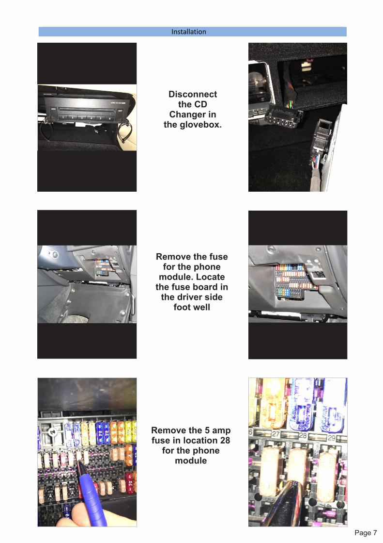
Disconnect the CD
Changer in the glovebox.
Remove the fuse for the phone
module. Locate the fuse board in
the driver side foot well
Remove the 5 amp fuse in location 28
for the phone module

Installation
Page 8
Remove the navigation drive
and the CD changer to make it easier to run
the supplied GPS extension lead.
DO NOT USEDO NOT USEFIBRE (D2B)FIBRE (D2B)DO NOT USEFIBRE (D2B)
REMOVE AND DISCARDREMOVE AND DISCARD THE PLASTIC THE PLASTIC
CABLE ASSEMBLYCABLE ASSEMBLY
REMOVE AND DISCARD THE PLASTIC
CABLE ASSEMBLY
DO NOT USEMUSTARD FAKRA
CONNECT SUPPLIED CONNECT SUPPLIED AERIAL AMP TO THEAERIAL AMP TO THE
WHITE FAKRAWHITE FAKRA
CONNECT SUPPLIED AERIAL AMP TO THE
WHITE FAKRA
Connect the supplied GPS
extension lead to the OEM GPS
socket behind the CD navigation
drive
AM/FM radio connections
Fibre opticconnector
Cableassembly

Page 9
Installation
Remove the 4 x trim clip from
original ZAB unit and clip into the supplied fasica
For the after market
microphone and possible DAB antenna (GT /
SPUR: N/A for US vehicles) remove the A pillar trim
Pry back trim next to door seal and use a feeder
cable to get through to the
glove box

Page 10
Installation
On GT / SPUR there are only
certain locations where you can put the DAB antenna
as the glass in the car is polarised and will affect
reception. Top of the front screen is
not polarised.
To remove the roof console you
will require a right angled pick.
Gently pry the OEM mic and
alarm sensor out of the consol and remove the 2 x t20
torx screws behind, then pull down console.
Once you have completed all the above, refit the trim panel and
test to ensure all functions.
Non-US vehicles only:

Operation
Troubleshooting
Page 11
For technical support please call 1-866-477-3336 Please ensure you have followed the install manual before calling
For full details on the operation of the BENTLEY-HUR fascia panel, please consult the USER GUIDE
Q. Steering wheel controls don't work.A. Please check the dip switches are set correctly for your chosen head unit.
Q. The BENTLEY-HUR panel is not functioning correctly after initial install. A. Please see “important note” on page 4.
Q. No GPS reception on after market unit.A. Check connection of the GPS extension lead (supplied in the kit).
Q. The LCD screen keeps turning off.A. Check to see if the LCD delay is turned on.
Q. Unwanted noise at low level.A. Please check if the audio isolator has been fitted (certain units may need this).
Q. The AM / FM is very poor.A. Check that the antenna amplifier is fitted correctly to the WHITE Fakra plug
and there is 12v+ on the blue wire going to the antenna amplifier.
NOTE: After the BENTLEY-HUR panel has been fitted, and due to the fact that certain
components have been disconnected, it will cause a fault code to be generated on the ODIS or VAGCOM diagnostic software systems.
Please ignore fault codes relating to (J523) / (J401) / (J412)
Top Related