


Languages
Pages
Legal

Service.
For internal use only
All rights reserved. Subject to technical modification.AUDI AGDepartment I/VK-35D-85045 IngolstadtFax 0841/89-36367140.2810.87.20Technical status as at 11/01Printed in Germany
The 6.0 l W12 enginein the Audi A8 - Part 2
Self-study programme 268
268
268
2
Contents
Engine, Mechanics
Belt drive/ancillaries . . . . . . . . . . . . . . . . . . . . . . . . . . . . . . . . . . . . . . . . . . . . . . . . . . . 3Water-cooled alternator . . . . . . . . . . . . . . . . . . . . . . . . . . . . . . . . . . . . . . . . . . . . . . . . 4Hydraulic/electric fan control . . . . . . . . . . . . . . . . . . . . . . . . . . . . . . . . . . . . . . . . . . . 6
Hydraulic fan circuit . . . . . . . . . . . . . . . . . . . . . . . . . . . . . . . . . . . . . . . . . . . . . . 6Power steering circuit . . . . . . . . . . . . . . . . . . . . . . . . . . . . . . . . . . . . . . . . . . . . . 7Hydraulic fan control. . . . . . . . . . . . . . . . . . . . . . . . . . . . . . . . . . . . . . . . . . . . . . 8Temperature sensor for radiator fan drive circuit -G382 . . . . . . . . . . . . . . . . . 9Electric fan control . . . . . . . . . . . . . . . . . . . . . . . . . . . . . . . . . . . . . . . . . . . . . . 10
Continued coolant circulation . . . . . . . . . . . . . . . . . . . . . . . . . . . . . . . . . . . . . . . . . . 10
Engine sub-systems
Induction system . . . . . . . . . . . . . . . . . . . . . . . . . . . . . . . . . . . . . . . . . . . . . . . . . . . . 12Exhaust system . . . . . . . . . . . . . . . . . . . . . . . . . . . . . . . . . . . . . . . . . . . . . . . . . . . . . . 14
Exhaust flap . . . . . . . . . . . . . . . . . . . . . . . . . . . . . . . . . . . . . . . . . . . . . . . . . . . . 17Crankcase breather system . . . . . . . . . . . . . . . . . . . . . . . . . . . . . . . . . . . . . . . . . . . . 18
System layout . . . . . . . . . . . . . . . . . . . . . . . . . . . . . . . . . . . . . . . . . . . . . . . . . . 18Secondary-air system. . . . . . . . . . . . . . . . . . . . . . . . . . . . . . . . . . . . . . . . . . . . . . . . . 20
System layout . . . . . . . . . . . . . . . . . . . . . . . . . . . . . . . . . . . . . . . . . . . . . . . . . . 20Vacuum system. . . . . . . . . . . . . . . . . . . . . . . . . . . . . . . . . . . . . . . . . . . . . . . . . . . . . . 23
System layout . . . . . . . . . . . . . . . . . . . . . . . . . . . . . . . . . . . . . . . . . . . . . . . . . . 23Exhaust-gas recirculation. . . . . . . . . . . . . . . . . . . . . . . . . . . . . . . . . . . . . . . . . . . . . . 24Fuel tank breather system - activated charcoal filter (ACF) . . . . . . . . . . . . . . . . . . 25
Engine management
Engine management concept . . . . . . . . . . . . . . . . . . . . . . . . . . . . . . . . . . . . . . . . . . 26System layout . . . . . . . . . . . . . . . . . . . . . . . . . . . . . . . . . . . . . . . . . . . . . . . . . . . . . . . 28
Sensors/actuators . . . . . . . . . . . . . . . . . . . . . . . . . . . . . . . . . . . . . . . . . . . . . . . 28Block diagram . . . . . . . . . . . . . . . . . . . . . . . . . . . . . . . . . . . . . . . . . . . . . . . . . . . . . . . 30Special features of Motronic ME7.1.1. . . . . . . . . . . . . . . . . . . . . . . . . . . . . . . . . . . . 32
Engine speed sender -G28 . . . . . . . . . . . . . . . . . . . . . . . . . . . . . . . . . . . . . . . . 34Sensor design . . . . . . . . . . . . . . . . . . . . . . . . . . . . . . . . . . . . . . . . . . . . . . . . . . 36Camshaft position senders . . . . . . . . . . . . . . . . . . . . . . . . . . . . . . . . . . . . . . . 37Sensor design . . . . . . . . . . . . . . . . . . . . . . . . . . . . . . . . . . . . . . . . . . . . . . . . . . 38
Oil temperature sender -G8 . . . . . . . . . . . . . . . . . . . . . . . . . . . . . . . . . . . . . . . . . . . . 42Detection of combustion missing. . . . . . . . . . . . . . . . . . . . . . . . . . . . . . . . . . . . . . . 42CAN data exchange . . . . . . . . . . . . . . . . . . . . . . . . . . . . . . . . . . . . . . . . . . . . . . . . . . 44Additional signals/interfaces. . . . . . . . . . . . . . . . . . . . . . . . . . . . . . . . . . . . . . . . . . . 46
Service
Notes on maintenance. . . . . . . . . . . . . . . . . . . . . . . . . . . . . . . . . . . . . . . . . . . . . . . . 48Workshop equipment/special tools . . . . . . . . . . . . . . . . . . . . . . . . . . . . . . . . . . . . . 50
AttentionNoteNew
Page
The self-study programme is not intended as a Workshop Manual. Values given are only intended to help explain the subject matter and relate to the software version applicable at the time of SSP compilation.
The self-study programme contains information on design features and functions.
Use should always be made of the latest technical publications when performing maintenance and repair work.
3
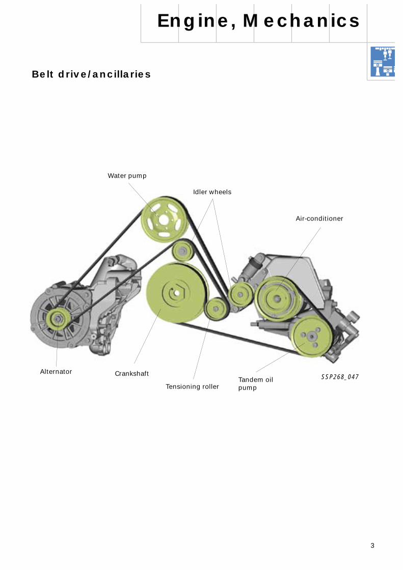
Belt drive/ancillaries
SSP268_047
Alternator
Air-conditioner
Water pump
Tandem oil pump
Idler wheels
Engine, Mechanics
Tensioning roller
Crankshaft
4
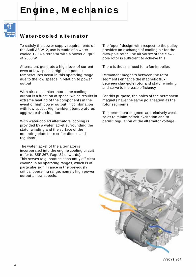
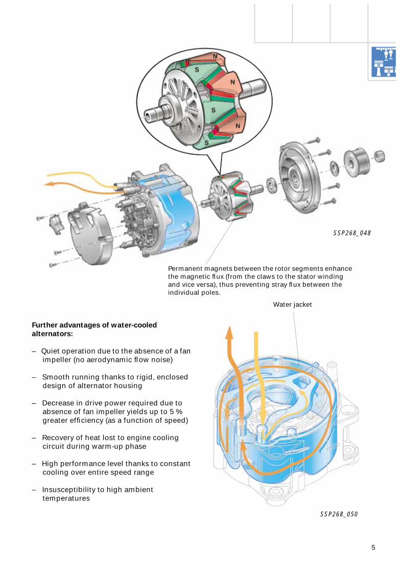
The "open" design with respect to the pulley provides an exchange of cooling air for the claw-pole rotor. The air vortex of the claw-pole rotor is sufficient to achieve this.
There is thus no need for a fan impeller.
Permanent magnets between the rotor segments enhance the magnetic flux between claw-pole rotor and stator winding and serve to increase efficiency.
For this purpose, the poles of the permanent magnets have the same polarisation as the rotor segments.
The permanent magnets are relatively weak so as to minimise self-excitation and to permit regulation of the alternator voltage.
Engine, Mechanics
SSP268_097
Water-cooled alternator
To satisfy the power supply requirements of the Audi A8 W12, use is made of a water-cooled 190 A alternator with a power output of 2660 W.
Alternators generate a high level of current even at low speeds. High component temperatures occur in this operating range due to the low speeds in relation to power output.
With air-cooled alternators, the cooling output is a function of speed, which results in extreme heating of the components in the event of high power output in combination with low speed. High ambient temperaturesaggravate this situation.
With water-cooled alternators, cooling is provided by a water jacket surrounding the stator winding and the surface of the mounting plate for rectifier diodes and regulator.
The water jacket of the alternator is incorporated into the engine cooling circuit(refer to SSP 267, Page 34 onwards). This serves to guarantee constantly efficient cooling in all operating ranges, which is of particular significance in the previously critical operating range, namely high power output at low speeds.
5
Further advantages of water-cooled alternators:
– Quiet operation due to the absence of a fan impeller (no aerodynamic flow noise)
– Smooth running thanks to rigid, enclosed design of alternator housing
– Decrease in drive power required due to absence of fan impeller yields up to 5 % greater efficiency (as a function of speed)
– Recovery of heat lost to engine cooling circuit during warm-up phase
– High performance level thanks to constant cooling over entire speed range
– Insusceptibility to high ambient temperatures
SSP268_050
Water jacket
SSP268_048
Permanent magnets between the rotor segments enhance the magnetic flux (from the claws to the stator winding and vice versa), thus preventing stray flux between the individual poles.
6
Operation
The hydraulic fan is controlled as a function of speed.
The speed of the hydraulic fan basically depends on the quantity of fluid flowing through the hydraulic motor.
In turn, the quantity of fluid is governed by the pump volume (pump speed) and the temperature of the hydraulic fluid.
The radiator fan valve -N313 (actuated by engine control unit 1 -J623) regulates the flow of fluid to the hydraulic motor and provides infinitely variable control of the fan speed.
Hydraulic/electric fan control
Heat from the engine cooling system is dissipated by way of a hydraulic fan system in combination with a 300 W electric fan.
Advantages of hydraulic fan system:
– High overall system performance
– High efficiency even at lowengine speeds
– No drain on vehicle electrical system
– Compact system allowing great flexibility of fitting location
– Infinite output control to suit requirements
The hydraulic fan system was adopted from the V8 TDI engine and adapted to match the specific features of the W12 engine (refer to SSP 226, Page 24 onwards).
A new addition is the temperature sensor for the radiator fan drive circuit -G382 (refer to Page
9
).
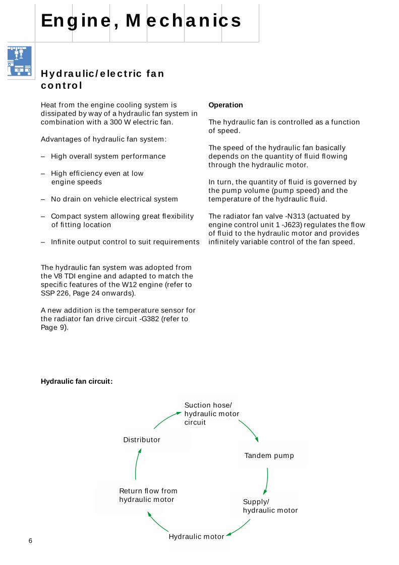
Hydraulic fan circuit:
Return flow from hydraulic motor
Hydraulic motor
Distributor
Suction hose/hydraulic motor circuit
Supply/hydraulic motor
Tandem pump
Engine, Mechanics
7
SSP268_077
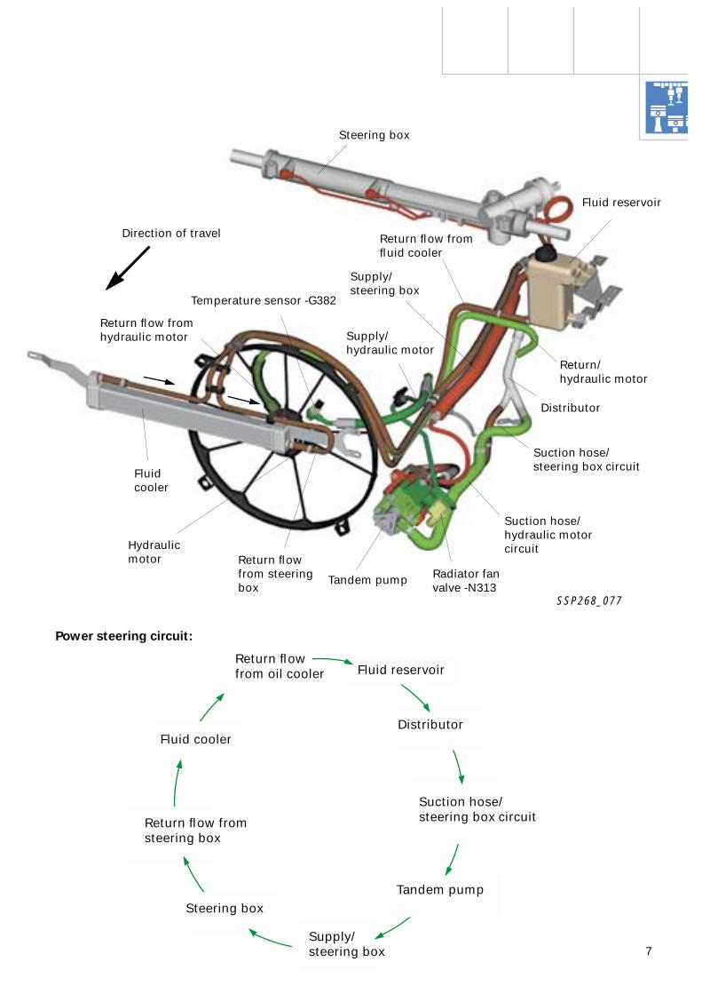
Fluid reservoir
Temperature sensor -G382
Distributor
Suction hose/steering box circuit
Tandem pump
Fluid cooler
Steering box
Return flow fromfluid cooler
Supply/hydraulic motor
Return flow fromhydraulic motor
Supply/steering box
Direction of travel
Radiator fan valve -N313
Return/hydraulic motor
Suction hose/hydraulic motor circuit
Power steering circuit:
Suction hose/steering box circuit
Distributor
Tandem pump
Fluid cooler
Return flow from oil cooler
Return flow from steering box
Steering box
Supply/steering box
Fluid reservoir
Hydraulic motor Return flow
from steering box
8
The radiator fan valve -N313 is actuated on a pulse-width modulated basis with a duty cycle (TVH) of between 0 and 100 %.
Valve -N313 is open when deenergised. In this status, the hydraulic fan attains its maximum speed of 2800 rpm.The fluid flow is then restricted by the pressure control valve in the pump.
For technical reasons the hydraulic fan is never completely shut down. Even when no cooling is required, it is actuated at a minimum speed of approx. 400 rpm.
Hydraulic fan control
On the basis of
coolant temperature
(-G62),
ambient temperature
(-G42) and
vehicle speed,
engine control unit 1 -J623 calculates a
specified fan speed
as a function of the
specified coolant temperature
.
Further parameters for specified fan speed:
– Air conditioner/compressor "ON"– Status of air-conditioner pressure switch
-F129 (for further details, refer to Page 46)
The fan speed is directly proportional to the volume (speed) of the hydraulic pump, the temperature of the hydraulic fluid and the switching status of the radiator fan valve -N313.
The current value for actuation of the radiator fan valve -N313 is calculated from the pump speed (derived from engine speed), the specified fan speed and the hydraulic fluid temperature (from -G382).
Engine, Mechanics
SSP268_028
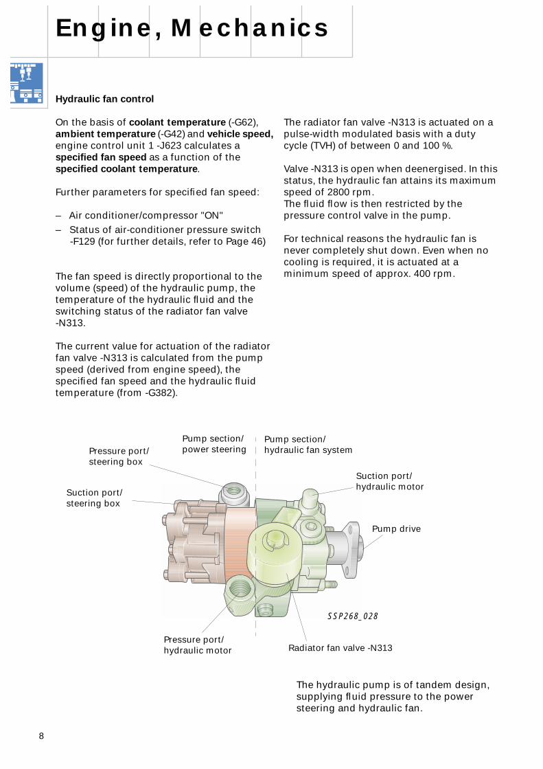
The hydraulic pump is of tandem design, supplying fluid pressure to the power steering and hydraulic fan.
Pressure port/steering box
Suction port/steering box
Pump section/hydraulic fan system
Suction port/hydraulic motor
Pump drive
Radiator fan valve -N313Pressure port/hydraulic motor
Pump section/power steering

9
Previous control method(V8 TDI engine without -G382)
The temperature of the hydraulic fluid is one of the fan speed parameters. With regard to the comfort speed, this was derived to date from the ambient temperature.
With allowance for production tolerances, this method of determining the temperature of the hydraulic fluid requires an appropriately large safety margin with respect to the acoustically acceptable comfort speed limit.
Optimum use can therefore not be made of the comfort speed range, with the fan having to run more frequently at maximum speed.
New control method (with -G382)
Sensing of the hydraulic fluid temperature (-G382) adds a further crucially important parameter which considerably improves hydraulic fan control, thus permitting more precise regulation and consequently better utilisation of the comfort speed range.More efficient use is made of the available potential up to the comfort speed limit.
As a result, the fan does not have to be operated as often at maximum speed with its associated high noise level.
Temperature sensor for radiator fan drive circuit -G382
The temperature sensor -G382 detects the temperature of the hydraulic fluid, which is of crucial importance to the viscosity of the fluid.
The viscosity influences the speed and thus the performance of the hydraulic fan.
For reasons of noise, the fan speed should not exceed approx. 2100 rpm. This speed limit is referred to in the following as "comfort speed".
If the coolant temperature exceeds roughly 115 °C, the hydraulic fan operates at maximum speed regardless of the associated noise level.
In view of pump losses, the following rules apply given a constant pump speed:
– High hydraulic fluid temperature Lower fan speed
– Low hydraulic fluid temperatureHigher fan speed
The internal gear of the hydraulic motor simultaneously acts as fan drive gear and is driven by the regulated fluid flow.
SSP268_027
Trochoid internal gear of hydraulic motor
Temperature sensor for radiator fandrive circuit -G382
10
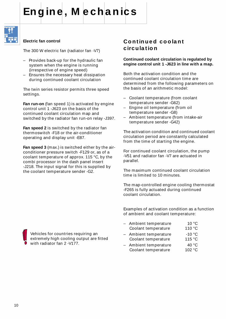
Electric fan control
The 300 W electric fan (radiator fan -V7)
– Provides back-up for the hydraulic fan system when the engine is running (irrespective of engine speed)
– Ensures the necessary heat dissipation during continued coolant circulation
The twin series resistor permits three speed settings.
Fan run-on
(fan speed 1)
is activated by engine control unit 1 -J623 on the basis of the continued coolant circulation map and switched by the radiator fan run-on relay -J397.
Fan speed 2
is switched by the radiator fan thermoswitch -F18 or the air-conditioner operating and display unit -E87.
Fan speed 3
(max.) is switched either by the air-conditioner pressure switch -F129 or, as of a coolant temperature of approx. 115 °C, by the combi processor in the dash panel insert -J218. The input signal for this is supplied by the coolant temperature sender -G2.
Vehicles for countries requiring an extremely high cooling output are fitted with radiator fan 2 -V177.
Engine, Mechanics
Continued coolant circulation
Continued coolant circulation is regulated by engine control unit 1 -J623 in line with a map.
Both the activation condition and the continued coolant circulation time are determined from the following parameters on the basis of an arithmetic model:
– Coolant temperature (from coolant temperature sender -G62)
– Engine oil temperature (from oil temperature sender -G8)
– Ambient temperature (from intake-air temperature sender -G42)
The activation condition and continued coolant circulation period are constantly calculated from the time of starting the engine.
For continued coolant circulation, the pump -V51 and radiator fan -V7 are actuated in parallel.
The maximum continued coolant circulation time is limited to 10 minutes.
The map-controlled engine cooling thermostat -F265 is fully actuated during continued coolant circulation.
Examples of activation condition as a function of ambient and coolant temperature:
– Ambient temperature 10 °CCoolant temperature 110 °C
– Ambient temperature -10 °CCoolant temperature 115 °C
– Ambient temperature 40 °CCoolant temperature 102 °C
11
S SS
X
1530
X
1530
J397 J101 J135
V7
N3931
F18
J271
F129
P
31
1 2
M
3
t°
4 5 6
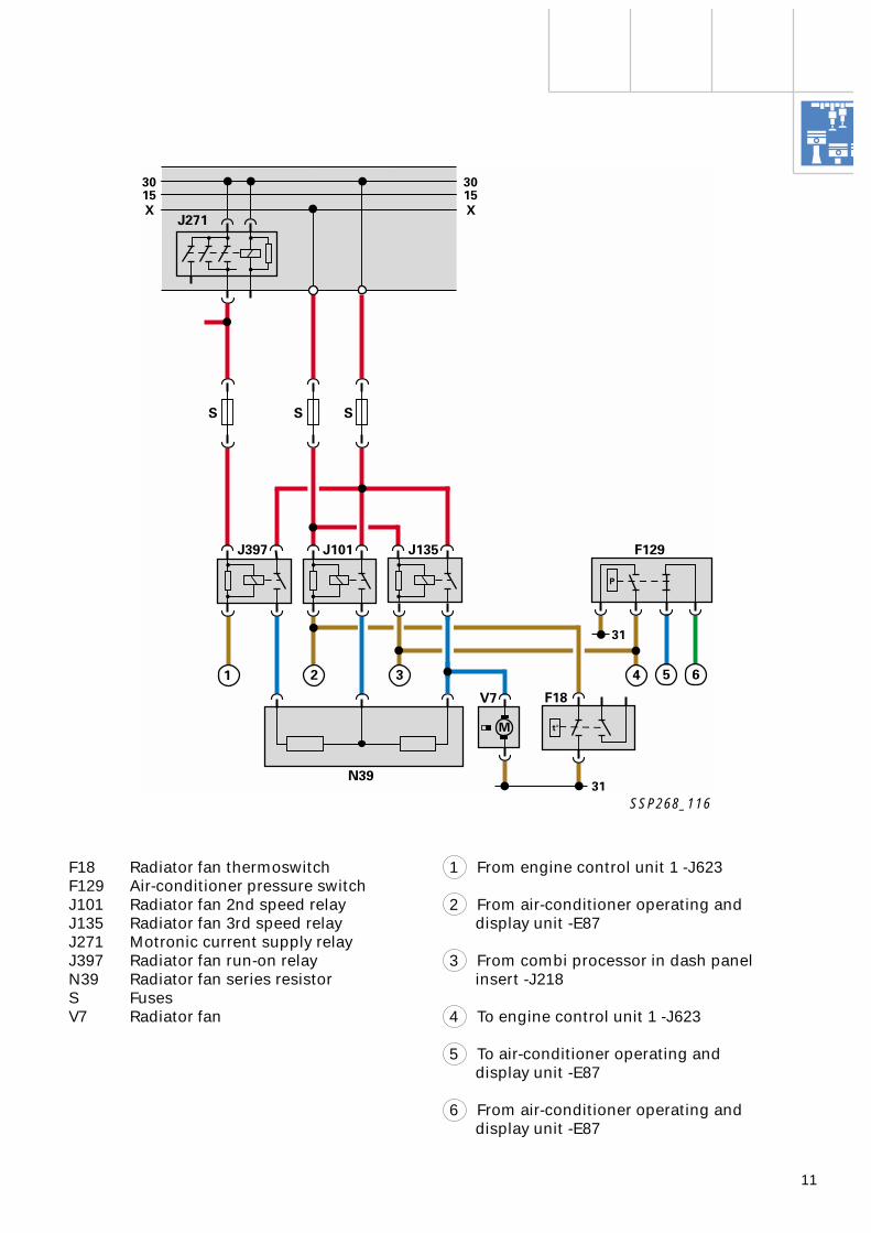
F18 Radiator fan thermoswitchF129 Air-conditioner pressure switchJ101 Radiator fan 2nd speed relayJ135 Radiator fan 3rd speed relayJ271 Motronic current supply relayJ397 Radiator fan run-on relayN39 Radiator fan series resistorS FusesV7 Radiator fan
From engine control unit 1 -J623
From air-conditioner operating and display unit -E87
From combi processor in dash panel insert -J218
To engine control unit 1 -J623
To air-conditioner operating and display unit -E87
From air-conditioner operating and display unit -E87
1
2
3
4
5
6
SSP268_116
12
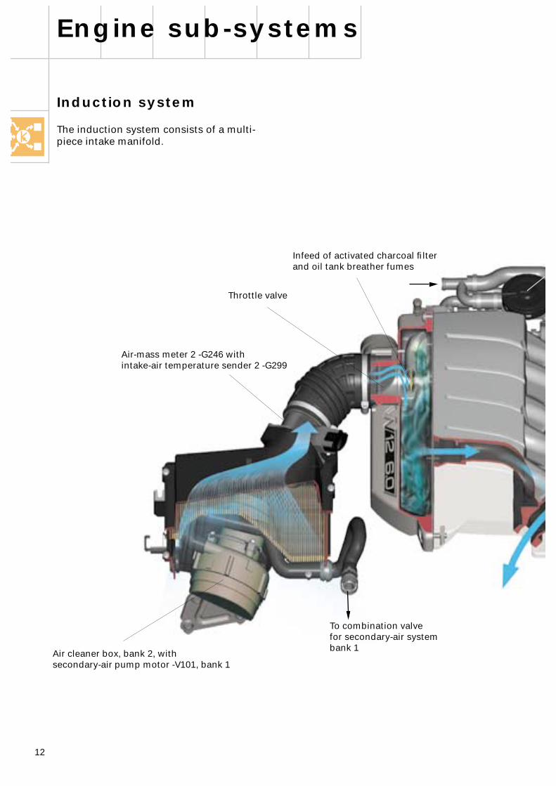
Induction system
The induction system consists of a multi-piece intake manifold.
Engine sub-systems
To combination valvefor secondary-air systembank 1
Air cleaner box, bank 2, withsecondary-air pump motor -V101, bank 1
Air-mass meter 2 -G246 withintake-air temperature sender 2 -G299
Infeed of activated charcoal filter and oil tank breather fumes
Throttle valve
13
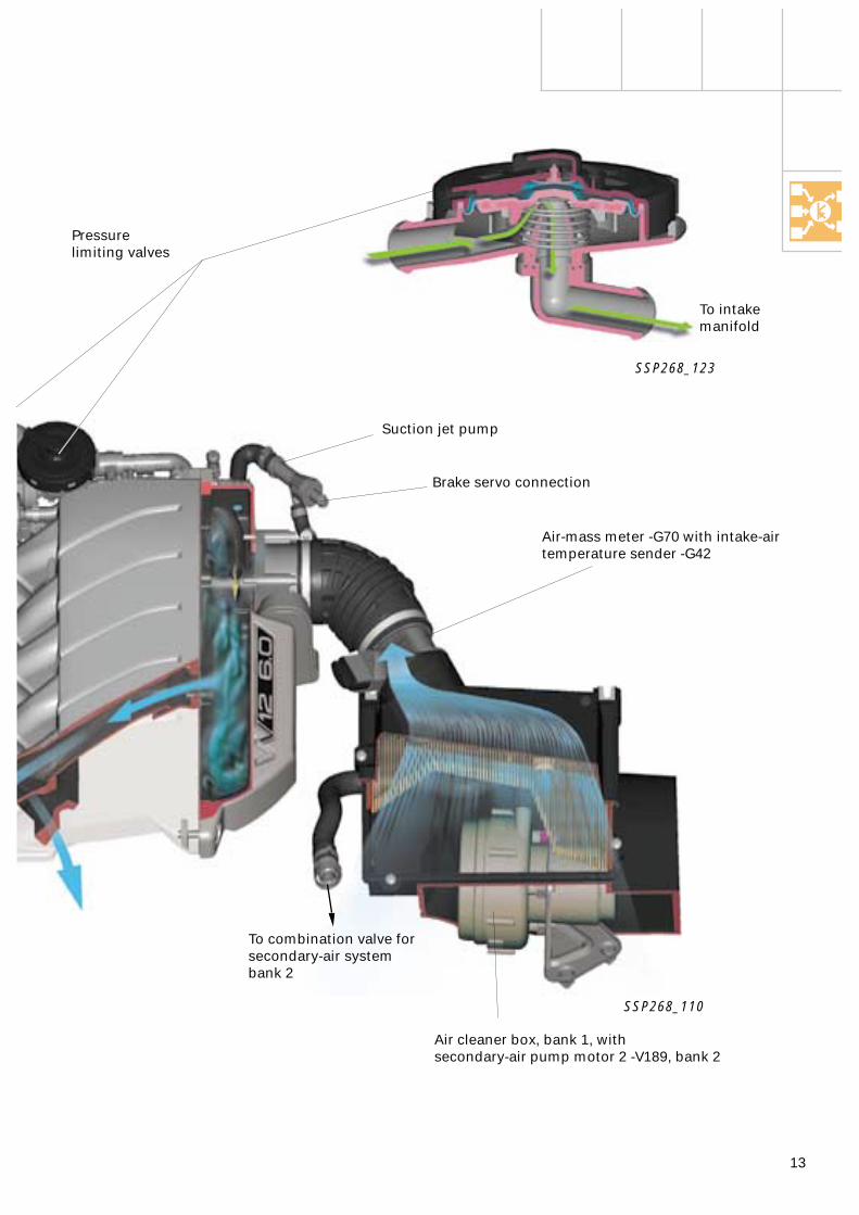
Suction jet pump
Air-mass meter -G70 with intake-air temperature sender -G42
To combination valve forsecondary-air systembank 2
Air cleaner box, bank 1, withsecondary-air pump motor 2 -V189, bank 2
SSP268_110
Brake servo connection
Pressurelimiting valves
SSP268_123
To intake manifold

14
Exhaust system
Engine sub-systems
G285 G286
G39G108
G130
G288
G287
G131
Main catalytic converters
Primary catalytic converterCylinders 1-3
Primary catalytic converterCylinders 10-12
Primary catalytic converterCylinders 7-9
Decoupling elements(do not kink by more than 10° to avoid damage)
Lambda probes
Upstream of CAT
Downstream of CAT
G39 G130
G108 G131
G285 G287
G286 G288
Length compensationflange
To offset production tolerances, the flange connections between the two primary catalytic converters of exhaust banks 1 and 3 and the intermediate pipe are provided with a length compensation flange.
For manufacturing reasons, the clamp-type flange connection at the primary catalytic converter (exhaust bank 1/3) is additionally welded after assembly in series production.
The primary catalytic converters are thus paired with the intermediate pipe. Consequently, replacement of the primary catalytic converters (exhaust bank 2/4) or intermediate pipe also involves replacing the associated primary catalytic converter (exhaust bank 1/3).
Double-D pipe
Primary catalytic converterCylinders 4-6
15
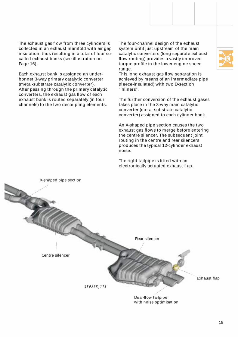
The four-channel design of the exhaust system until just upstream of the main catalytic converters (long separate exhaust flow routing) provides a vastly improved torque profile in the lower engine speed range.This long exhaust gas flow separation is achieved by means of an intermediate pipe (fleece-insulated) with two D-section "inliners".
The further conversion of the exhaust gases takes place in the 3-way main catalytic converter (metal-substrate catalytic converter) assigned to each cylinder bank.
An X-shaped pipe section causes the two exhaust gas flows to merge before entering the centre silencer. The subsequent joint routing in the centre and rear silencers produces the typical 12-cylinder exhaust noise.
The right tailpipe is fitted with an electronically actuated exhaust flap.
The exhaust gas flow from three cylinders is collected in an exhaust manifold with air gap insulation, thus resulting in a total of four so-called exhaust banks (see illustration on Page 16).
Each exhaust bank is assigned an under-bonnet 3-way primary catalytic converter (metal-substrate catalytic converter). After passing through the primary catalytic converters, the exhaust gas flow of each exhaust bank is routed separately (in four channels) to the two decoupling elements.
X-shaped pipe section
Centre silencer
Dual-flow tailpipewith noise optimisation
Exhaust flap
Rear silencer
SSP268_113
16
Engine sub-systems
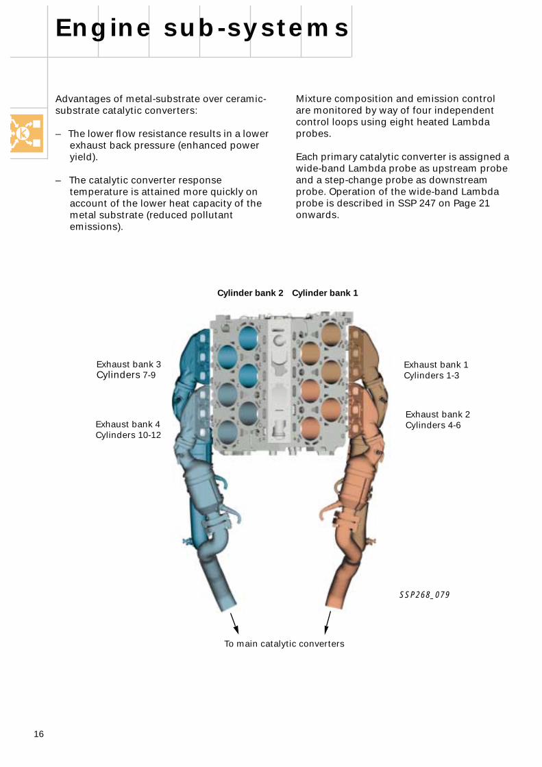
Mixture composition and emission control are monitored by way of four independent control loops using eight heated Lambda probes.
Each primary catalytic converter is assigned a wide-band Lambda probe as upstream probe and a step-change probe as downstream probe. Operation of the wide-band Lambda probe is described in SSP 247 on Page 21 onwards.
SSP268_079
Exhaust bank 3
Cylinders
7-9
Exhaust bank 4Cylinders 10-12
Exhaust bank 1Cylinders 1-3
Exhaust bank 2Cylinders 4-6
To main catalytic converters
Cylinder bank 2 Cylinder bank 1
Advantages of metal-substrate over ceramic-substrate catalytic converters:
– The lower flow resistance results in a lower exhaust back pressure (enhanced power yield).
– The catalytic converter response temperature is attained more quickly on account of the lower heat capacity of the metal substrate (reduced pollutant emissions).
17
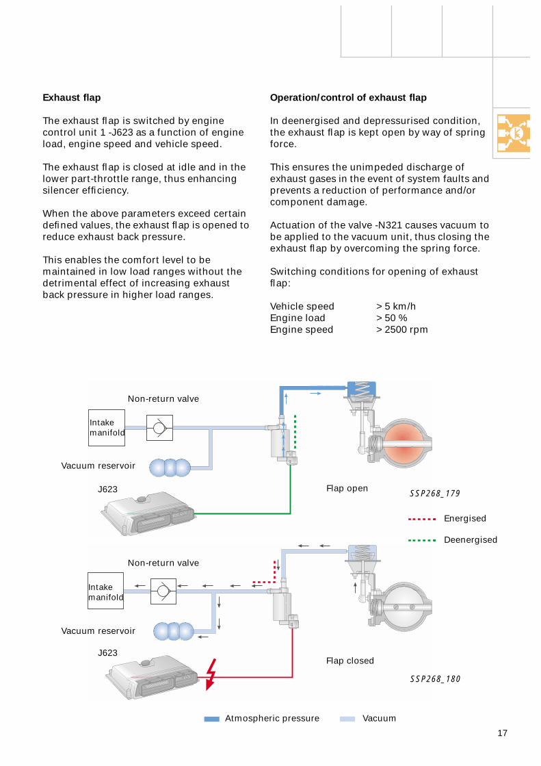
Exhaust flap
The exhaust flap is switched by engine control unit 1 -J623 as a function of engine load, engine speed and vehicle speed.
The exhaust flap is closed at idle and in the lower part-throttle range, thus enhancing silencer efficiency.
When the above parameters exceed certain defined values, the exhaust flap is opened to reduce exhaust back pressure.
This enables the comfort level to be maintained in low load ranges without the detrimental effect of increasing exhaust back pressure in higher load ranges.
Operation/control of exhaust flap
In deenergised and depressurised condition, the exhaust flap is kept open by way of spring force.
This ensures the unimpeded discharge of exhaust gases in the event of system faults and prevents a reduction of performance and/or component damage.
Actuation of the valve -N321 causes vacuum to be applied to the vacuum unit, thus closing the exhaust flap by overcoming the spring force.
Switching conditions for opening of exhaust flap:
Vehicle speed > 5 km/hEngine load > 50 %Engine speed > 2500 rpm
SSP268_180
SSP268_179
Flap open
Flap closed
Atmospheric pressure Vacuum
Non-return valve
Vacuum reservoir
J623
J623
Intakemanifold
Energised
Deenergised
Intakemanifold
Vacuum reservoir
Non-return valve
18
Engine sub-systems
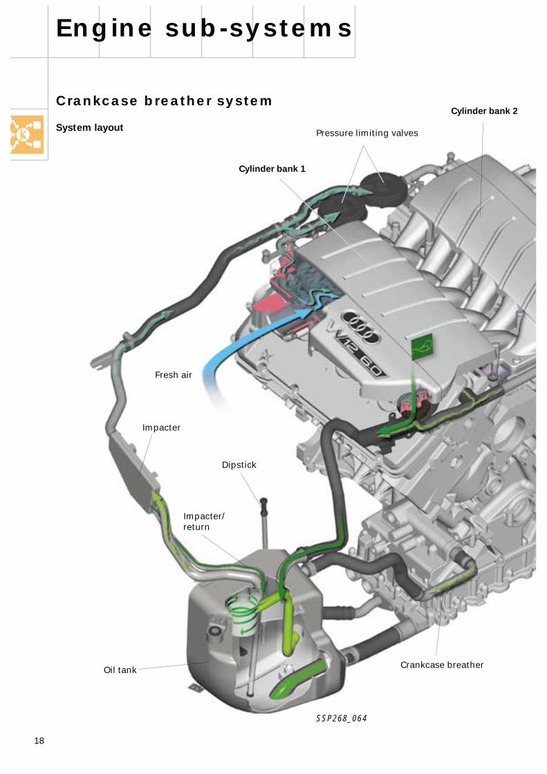
Crankcase breather system
System layout
Impacter
Oil tank
Dipstick
Pressure limiting valves
Cylinder bank 1
Crankcase breather
Cylinder bank 2
SSP268_064
Impacter/return
Fresh air
19
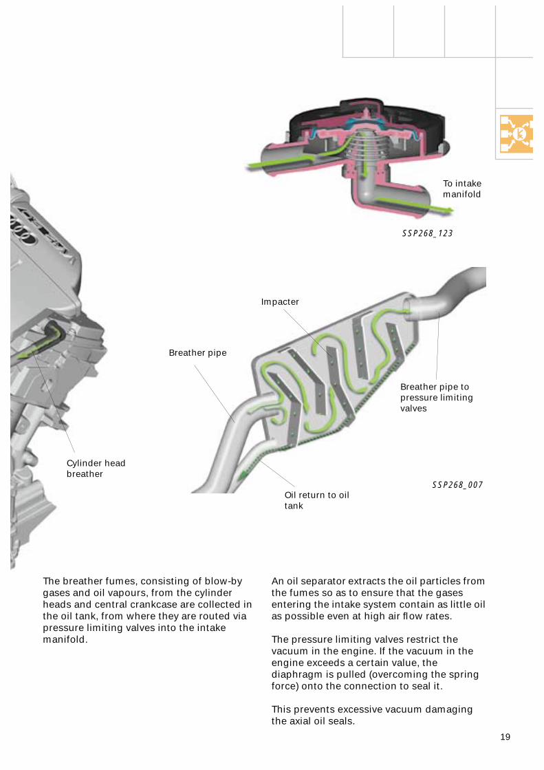
Cylinder headbreather
An oil separator extracts the oil particles from the fumes so as to ensure that the gases entering the intake system contain as little oil as possible even at high air flow rates.
The pressure limiting valves restrict the vacuum in the engine. If the vacuum in the engine exceeds a certain value, the diaphragm is pulled (overcoming the spring force) onto the connection to seal it.
This prevents excessive vacuum damaging the axial oil seals.
The breather fumes, consisting of blow-by gases and oil vapours, from the cylinder heads and central crankcase are collected in the oil tank, from where they are routed via pressure limiting valves into the intake manifold.
Breather pipe
Breather pipe to pressure limiting valves
Oil return to oil tank
SSP268_007
Impacter
To intake manifold
SSP268_123
20
Engine sub-systems
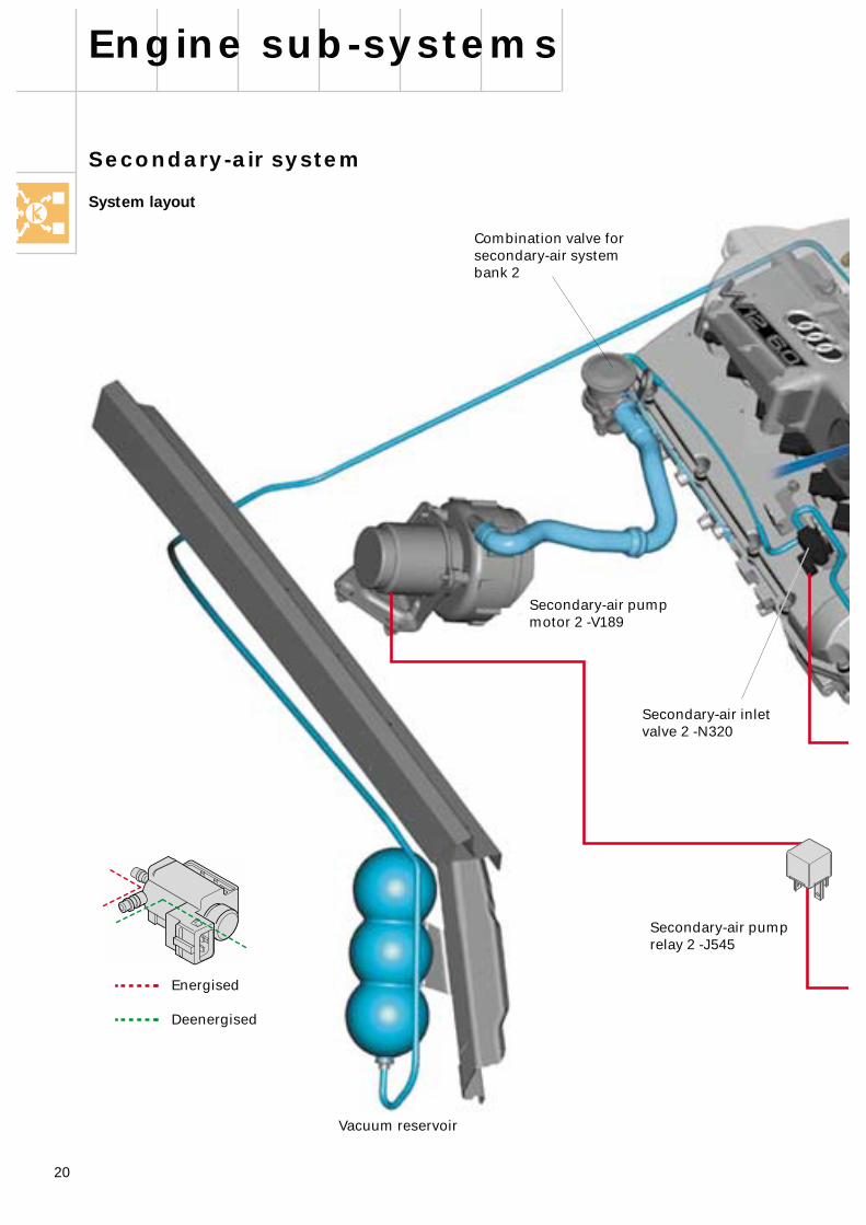
Vacuum reservoir
Combination valve forsecondary-air systembank 2
Secondary-air inlet valve 2 -N320
Secondary-air pump relay 2 -J545
Secondary-air pump motor 2 -V189
Energised
Deenergised
Secondary-air system
System layout
21
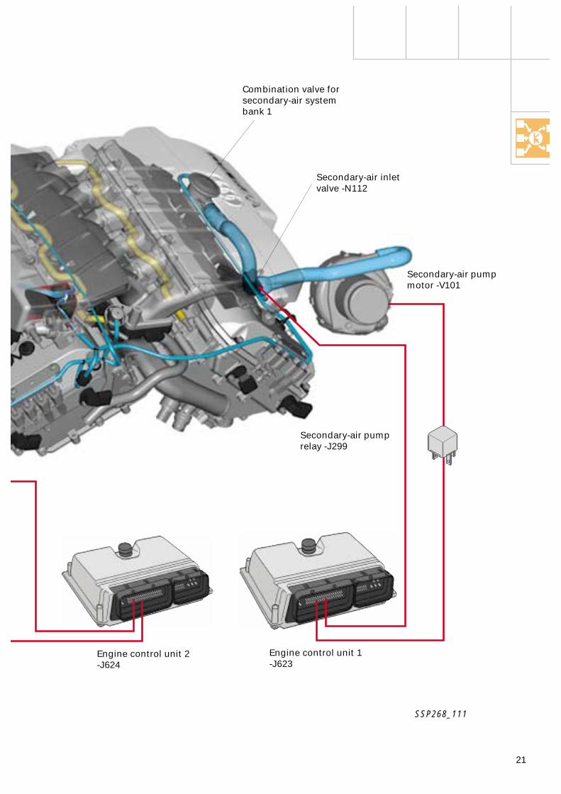
Combination valve forsecondary-air systembank 1
Secondary-air inletvalve -N112
SSP268_111
Engine control unit 2-J624
Engine control unit 1-J623
Secondary-air pump relay -J299
Secondary-air pump motor -V101

22
Engine sub-systems
SSP268_076
A special feature of the secondary-air system is that the secondary air is routed by way of ducts in the exhaust manifolds back to the secondary-air ducts in the cylinder head.
The secondary-air ducts in the cylinder head route the secondary air directly behind the exhaust valves.
Operation of the secondary-air system and the individual components is described in detail in SSP 217 on Page 32 onwards.
Discharge of secondary air directly at exhaust valve
Secondary-air duct
From combination valve for secondary-air system
Duct routingin exhaust manifold
23
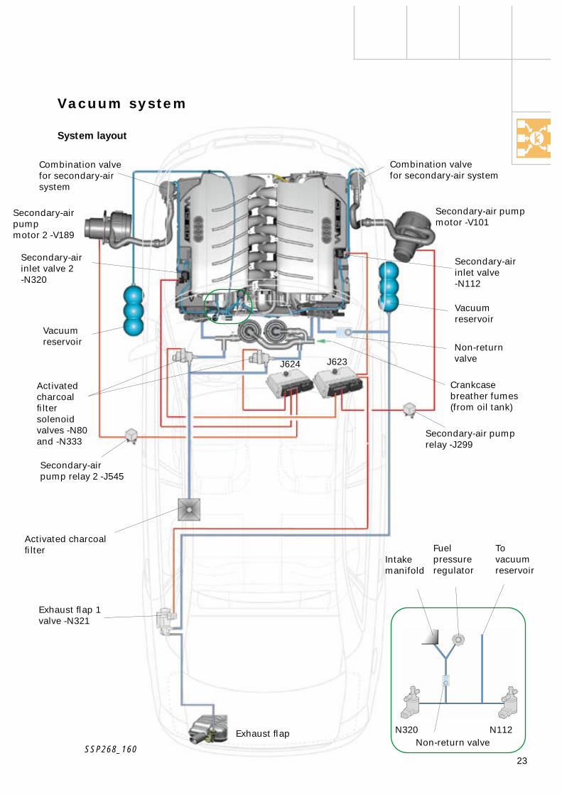
Exhaust flap
Exhaust flap 1valve -N321
Secondary-air pumpmotor 2 -V189
Secondary-air pump motor -V101
Secondary-air pump relay 2 -J545
Secondary-air pump relay -J299
Non-returnvalve
Vacuumreservoir
Secondary-air inlet valve 2-N320
J624 J623
Secondary-air inlet valve -N112
Combination valvefor secondary-air system
Activated charcoal filter
Activated charcoal filter solenoid valves -N80 and -N333
To vacuumreservoir
Combination valve for secondary-air system
Vacuumreservoir
Crankcase breather fumes (from oil tank)
N320 N112
Vacuum system
System layout
Fuel pressure regulator
Intake manifold
Non-return valveSSP268_160
24
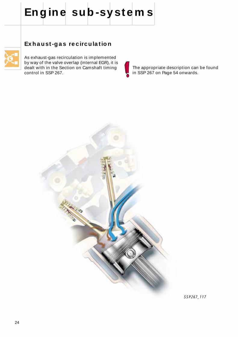
SSP267_117
The appropriate description can be foundin SSP 267 on Page 54 onwards.
Exhaust-gas recirculation
As exhaust-gas recirculation is implemented by way of the valve overlap (internal EGR), it is dealt with in the Section on Camshaft timing control in SSP 267.
Engine sub-systems
25
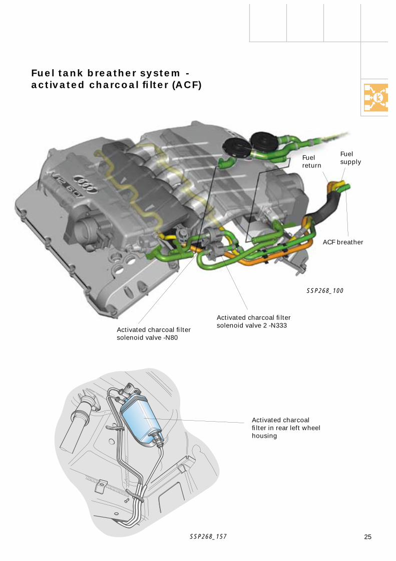
Fuel tank breather system - activated charcoal filter (ACF)
Activated charcoal filtersolenoid valve -N80
Activated charcoal filtersolenoid valve 2 -N333
Fuelreturn
Fuelsupply
ACF breather
SSP268_100
SSP268_157
Activated charcoal filter in rear left wheel housing

26
BOSCH BOSCHBOSCH BOSCH
Control unit/cylinder bank assignment identification is provided by way of so-called pin encoding in the wiring harness. To provide a clear distinction, the wiring harness to each control unit is wound with differently coloured tape.
Pin encoding means that the interface pin 49 of engine control unit 1 -J623 is connected to terminal 15 and pin 49 of engine control unit 2 -J624 is connected to terminal 31.
On account of the twin control unit concept attention must be paid to the following:
Both control units must …
… have the same software version… be matched to the cruise control system
(CCS)… be matched to the immobilizer… be viewed as separate entities for self-
diagnosis… have the same encoding
Engine managementconcept
Engine management
The engine management system for the W12 engine - Motronic ME7.1.1 - takes the form of a so-called twin control unit concept.
The two control units are fully identical and each is assigned to one cylinder bank. This means that the two cylinder banks are to be viewed as separate engines.
Certain sub-functions are however common to both control units:
– Engine control unit 1 -J623for cylinder bank 1
– Engine control unit 2 -J624for cylinder bank 2
The Motronic ME7.1.1 engine management system is a more advanced version of the Motronic ME7.1, which was described in SSPs 198 and 217.
Relevant information can be found as follows:
– Torque-oriented engine management (SSP 198, Page 33 onwards)
– Electrically operated throttle valve (electronic throttle function - SSP 198, Page 36 onwards; SSP 217, Page 42)
– Sensors (SSP 198, Page 49 onwards)– Rapid starting functions (SSP 217,
Page 40 onwards)– Engine run-out detection (SSP 217,
Page 41)
SSP268_129
Engine control unit 2 -J624 Engine control unit 1 -J623
27
K50
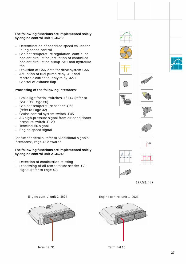
The following functions are implemented solely by engine control unit 1 -J623:
– Determination of specified speed values for idling speed control
– Coolant temperature regulation, continued coolant circulation, actuation of continued coolant circulation pump -V51 and hydraulic fan
– Provision of CAN data for drive system CAN– Actuation of fuel pump relay -J17 and
Motronic current supply relay -J271– Control of exhaust flap
Processing of the following interfaces:
– Brake light/pedal switches -F/-F47 (refer to SSP 198, Page 56)
– Coolant temperature sender -G62(refer to Page 32)
– Cruise control system switch -E45– AC high-pressure signal from air-conditioner
pressure switch -F129– Terminal 50 signal– Engine speed signal
For further details, refer to "Additional signals/interfaces", Page 43 onwards.
The following functions are implemented solely by engine control unit 2 -J624:
– Detection of combustion missing– Processing of oil temperature sender -G8
signal (refer to Page 42)
SSP268_148
Terminal 15Terminal 31
Engine control unit 2 -J624 Engine control unit 1 -J623
28
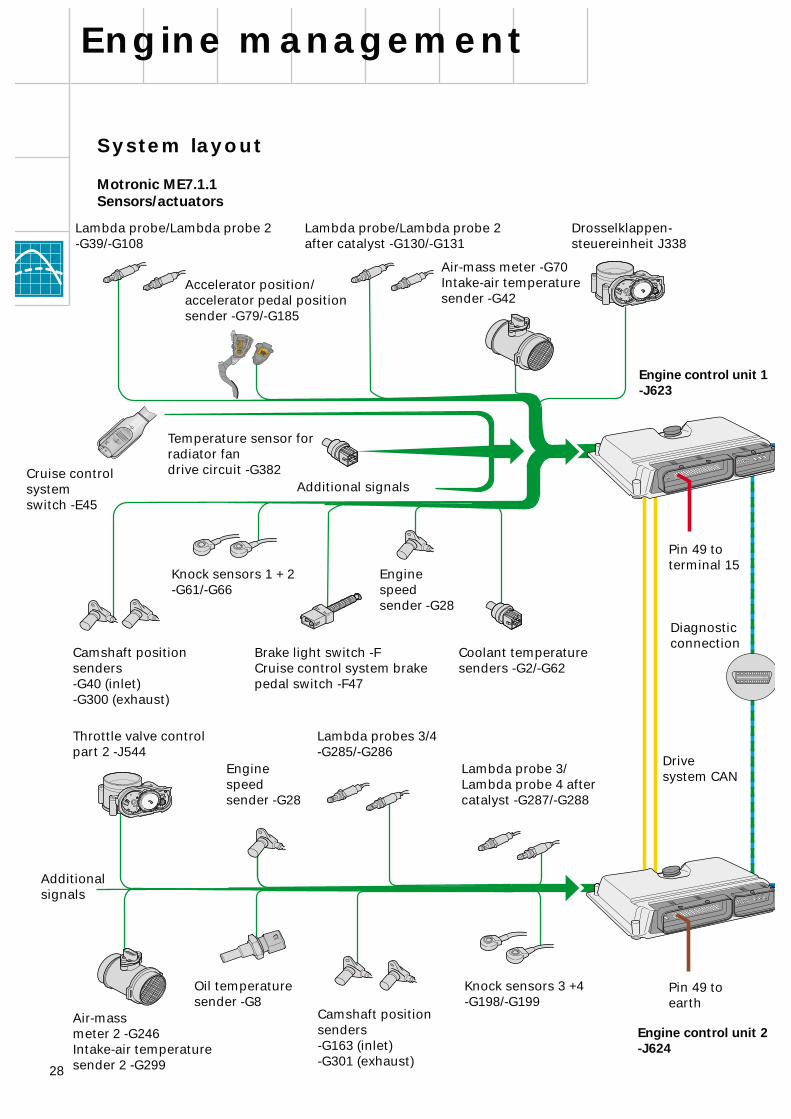
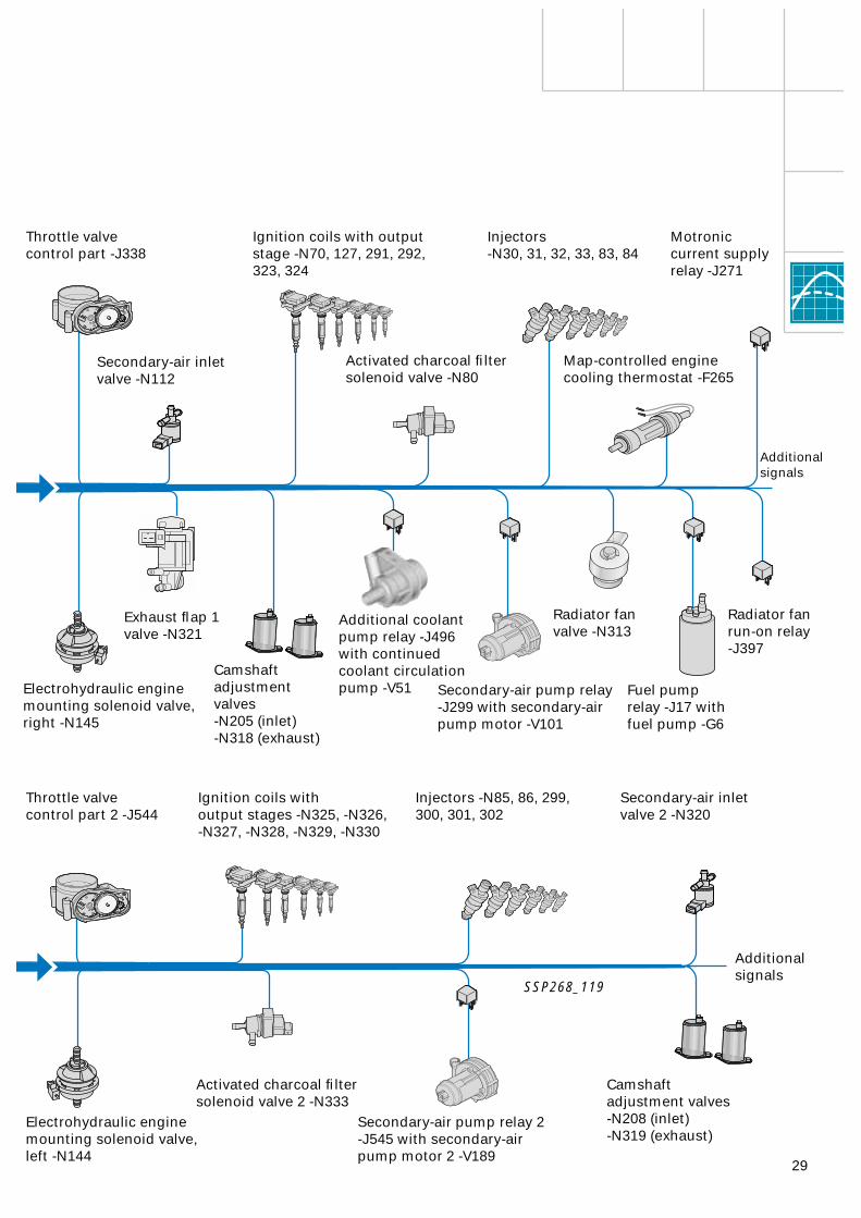
System layout
Motronic ME7.1.1Sensors/actuators
Engine management
Lambda probe/Lambda probe 2after catalyst -G130/-G131
Lambda probe/Lambda probe 2-G39/-G108
Accelerator position/accelerator pedal position sender -G79/-G185
Air-mass meter -G70Intake-air temperature sender -G42
Drosselklappen-steuereinheit J338
Additional signals
Camshaft position senders-G40 (inlet)-G300 (exhaust)
Knock sensors 1 + 2 -G61/-G66
Enginespeedsender -G28
Brake light switch -FCruise control system brake pedal switch -F47
Coolant temperature senders -G2/-G62
Throttle valve control part 2 -J544
Lambda probes 3/4 -G285/-G286
Lambda probe 3/Lambda probe 4 after catalyst -G287/-G288
Air-massmeter 2 -G246Intake-air temperature sender 2 -G299
Camshaft position senders-G163 (inlet)-G301 (exhaust)
Knock sensors 3 +4 -G198/-G199
Engine control unit 2 -J624
Engine control unit 1 -J623
Enginespeedsender -G28
Diagnosticconnection
Oil temperaturesender -G8
Temperature sensor forradiator fandrive circuit -G382Cruise control
systemswitch -E45
Pin 49 to terminal 15
Pin 49 to earth
Additional signals
Drive system CAN
29
Throttle valvecontrol part -J338
Secondary-air inletvalve -N112
Ignition coils with output stage -N70, 127, 291, 292, 323, 324
Activated charcoal filter solenoid valve -N80
Injectors-N30, 31, 32, 33, 83, 84
Radiator fan valve -N313
Secondary-air pump relay -J299 with secondary-air pump motor -V101
Camshaftadjustmentvalves-N205 (inlet)-N318 (exhaust)
Electrohydraulic engine mounting solenoid valve, right -N145
Additional coolant pump relay -J496with continued coolant circulationpump -V51
Exhaust flap 1valve -N321
Injectors -N85, 86, 299, 300, 301, 302
Ignition coils withoutput stages -N325, -N326, -N327, -N328, -N329, -N330
Throttle valvecontrol part 2 -J544
Secondary-air inletvalve 2 -N320
Secondary-air pump relay 2 -J545 with secondary-air pump motor 2 -V189
Activated charcoal filter solenoid valve 2 -N333
Electrohydraulic engine mounting solenoid valve, left -N144
Camshaftadjustment valves-N208 (inlet)-N319 (exhaust)
SSP268_119
Map-controlled engine cooling thermostat -F265
Motronic current supply relay -J271
Fuel pumprelay -J17 withfuel pump -G6
Radiator fan run-on relay -J397
Additional signals
Additional signals

Additional signals
Terminal 50
To radiator fan run-on relay -J397
AC high-pressure signal from air-conditioner pressure switch -F129 (high-pressure switch)
AC requirement signal(from air-conditioner control unit -E87)
Compressor "ON/OFF" signal
Crash signal
Engine speed signal
CAN Low/drive
CAN High/drive
1
2
3
4
5
6
7
8
9
31
S SS SS S S
15
X
1530
N318 N205 N112 N321
M
M
J17
N145 N80
J299
V101
31
G6
N31N32N33N83
N84
G70/G42
+-
mL
C
N30
D
N313
B
49
QP
15
N127
N291
N292
N323
N324
+
-
A
XC
G
E
A
D C
N70
01 22a
0,2a
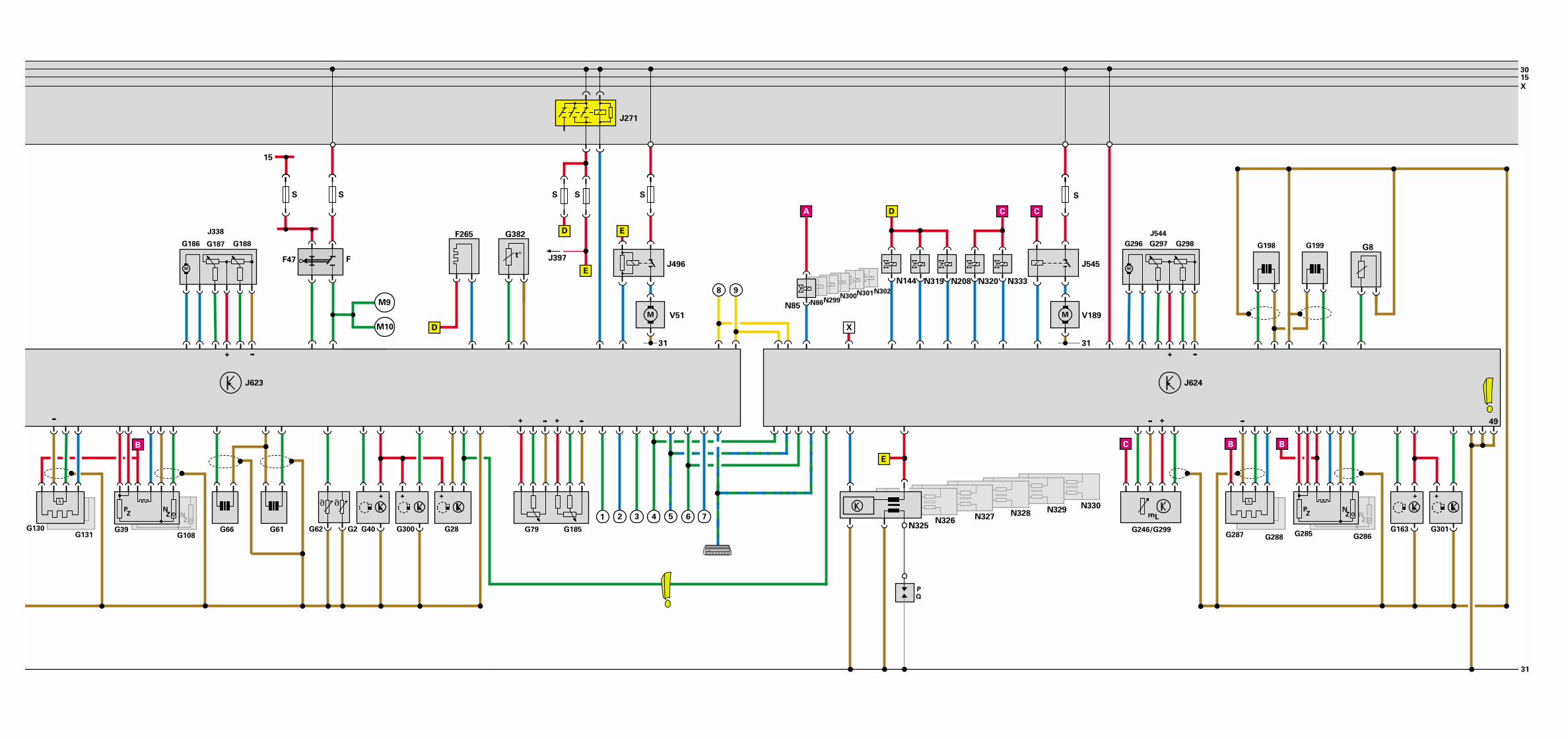
Block diagram
Motronic ME7.1.1
A Battery
E45 Cruise control system switch
F Brake light switchF47 Cruise control system brake pedal
switchF265 Map-controlled engine cooling
thermostat
G2 Coolant temperature senderG6 Fuel pump G8 Oil temperature senderG28 Engine speed senderG39 Lambda probeG40 Inlet camshaft position sender/
cylinder bank 1G42 Intake-air temperature senderG61 Knock sensor 1G62 Coolant temperature senderG66 Knock sensor 2G70 Air-mass meterG79 Accelerator position senderG108 Lambda probe 2G130 Lambda probe after catalystG131 Lambda probe 2 after catalystG163 Inlet camshaft position sender/
cylinder bank 2G185 Accelerator pedal position
sender 2G186 Throttle valve drive
(electric throttle operation)G187 Throttle valve drive angle sender 1
(electric throttle operation)G188 Throttle valve drive angle sender 2
(electric throttle operation)G198 Knock sensor 3G199 Knock sensor 4G246 Air-mass meter 2G285 Lambda probe 3G286 Lambda probe 4G287 Lambda probe 3 after catalystG288 Lambda probe 4 after catalystG296 Throttle valve drive 2G297 Angle sender 1 for throttle valve
drive 2G298 Angle sender 2 for throttle valve
drive 2G299 Intake-air temperature sender 2
G300 Exhaust camshaft position sender/cylinder bank 1
G301 Exhaust camshaft position sender/cylinder bank 2
G382 Temperature sensor for radiator fandrive circuit
J17 Fuel pump relayJ271 Motronic current supply relayJ299 Secondary-air pump relayJ338 Throttle valve control partJ397 Radiator fan run-on relayJ496 Additional coolant pump relayJ544 Throttle valve control part 2J545 Secondary-air pump relay 2J623 Engine control unit 1J624 Engine control unit 2
M9 Brake light bulb, leftM10 Brake light bulb, right
N30 Injector, cylinder 1N31 Injector, cylinder 2N32 Injector, cylinder 3N33 Injector, cylinder 4N70 Ignition coil 1 with output stageN80 Activated charcoal filter
solenoid valveN83 Injector, cylinder 5N84 Injector, cylinder 6N85 Injector, cylinder 7N86 Injector, cylinder 8N112 Secondary-air inlet valveN127 Ignition coil 2 with output stageN144 Electrohydraulic engine mounting
solenoid valve, leftN145 Electrohydraulic engine mounting
solenoid valve, rightN205 Camshaft adjustment valve 1N208 Camshaft adjustment valve 2N291 Ignition coil 3 with output stageN292 Ignition coil 4 with output stageN299 Injector, cylinder 9N300 Injector, cylinder 10N301 Injector, cylinder 11N302 Injector, cylinder 12N313 Radiator fan valve
Engine management
N318 Exhaust camshaft controlvalve 1
N319 Exhaust camshaft controlvalve 2
N320 Seconday-air inlet valve 2N321 Exhaust flap 1 valveN323 Ignition coil 5 with final output stageN324 Ignition coil 6 with final output stageN325 Ignition coil 7 with final output stageN326 Ignition coil 8 with final output stageN327 Ignition coil 9 with final output stageN328 Ignition coil 10 with final output stageN329 Ignition coil 11 with final output stageN330 Ignition coil 12 with final output stageN333 Activated charcoal filter solenoid
valve 2
S Fuses
V51 Continued coolant circulation pumpV101 Secondary-air pump motorV189 Secondary-air pump motor 2
Colour code
= Input signal
= Output signal
= Positive supply
= Earth
= CAN BUS
30
{
{
Power supply fromFuel pump relay -J17
Power supply fromMotronic current supplyrelay -J271
Connections withinblock diagram
A
B
C
D
E
X
31
3015
X
S S S
G382F265
S
G8
S S
15
F47
M10
G40 G300G66 G61G131
J623
G28G62
E
G246/G299
C
mL
G163 G301
N144 N319 N320
M
N208
J545
V189
31
N86N299
N302N301N300
G296 G297
M
G298
N333
G198 G199
t°
M
J496
V51
31
J271
QP
N325G2
J544
J397F
D
A
G108
-
B
λλPZ
NZ
λλPZ
NZ
G288
M9
+ + +
G79 G185
+ - + -
1 2 3N326
N327 N328
+ +
N85
+ -
D E
X
J624
N329N330
BB
-+-
G285 G286
PZ
NZ
λ
G287G39
λ
G130
4
8 9
65 7
E
PZ
NZ
D C
49
G186 G187
M
G188
+ -
J338
C
32
104
3
2
3
2
4
6
8
103
3
2
4
6
8
102
8
-30 -20 0 20 6040 80 100 120
Special features ofMotronic ME7.1.1
The Motronic ME7.1.1 is a more advanced version of the Motronic ME7.1. Important new features:
– Greater computer capacity on account of new computer-bound sub-functions
– Extension of control unit activities after switching off ignition with the aid of main relay concept
– Infinitely variable adjustment of inlet andexhaust camshafts (refer to SSP 267,Page 59 onwards)
– Designed to suit new wide-band Lambda probes upstream of catalytic converter (refer to Page 14)
Engine management
– Designed for coolant temperature regulation
– Enhanced evaluation of signals from coolant temperature sender -G62
– Management of additional and new CAN messages (refer to Page 44)
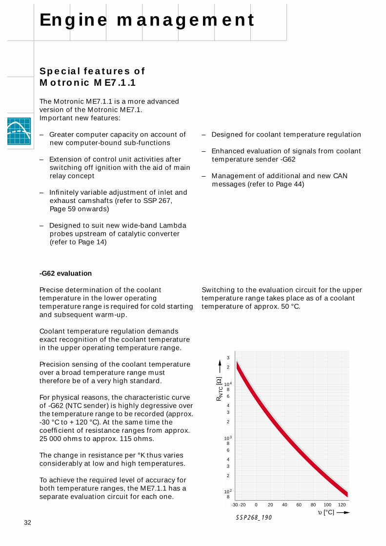
-G62 evaluation
Precise determination of the coolant temperature in the lower operating temperature range is required for cold starting and subsequent warm-up.
Coolant temperature regulation demands exact recognition of the coolant temperature in the upper operating temperature range.
Precision sensing of the coolant temperature over a broad temperature range must therefore be of a very high standard.
For physical reasons, the characteristic curve of -G62 (NTC sender) is highly degressive over the temperature range to be recorded (approx. -30 °C to + 120 °C). At the same time the coefficient of resistance ranges from approx. 25 000 ohms to approx. 115 ohms.
The change in resistance per °K thus varies considerably at low and high temperatures.
To achieve the required level of accuracy for both temperature ranges, the ME7.1.1 has a separate evaluation circuit for each one.
Switching to the evaluation circuit for the upper temperature range takes place as of a coolant temperature of approx. 50 °C.
SSP268_190
R
NTC
[
W
]
u
[°C
]
33
After switching off the ignition, the ignition coils continue to be actuated until the engine stops in order to ensure ignition of the fuel already injected. This means that no unburned fuel/air mixture reaches the exhaust system, thus reducing the level of exhaust emissions.
The camshaft adjustment valves also remain actuated until the engine stops following ignition switch-off to ensure that the camshafts are kept in the appropriate position until the engine has stopped.
The engine mounting solenoid valves are actuated to provide smooth, vibration-free engine shutoff.
The solenoid valve for the hydraulic fan is actuated to prevent brief fan speed increase.
As engine control unit 1 is responsible for control of the entire continued coolant circulation process, it must be possible to actuate the control elements (relay -J496, relay -J397 and thermostat -F265).
Main relay concept
To date, the power supply for the sensors andactuators was provided largely via the fuel pump relay -J17.
A new addition is the Motronic current supply relay -J271 (main relay).
As with the fuel pump relay -J17, the Motronic current supply relay -J271 is actuated by engine control unit 1. Thanks to the Motronic current supply relay -J271, the engine control units can still implement certain functions after the engine has been switched off (ignition OFF).
The following sensors/actuators are supplied with power by the Motronic current supply relay -J271:
– Engine control unit 1– Engine control unit 2– Ignition coils of cylinder bank 1– Ignition coils of cylinder bank 2– Camshaft adjustment valves– Engine mounting solenoid valves– Radiator fan valve -N313– Additional coolant pump relay -J496
(continued coolant circulation pump -V51)– Radiator fan run-on relay -J397
(radiator fan -V7)– Map-controlled engine cooling thermostat
-F265
Refer to block diagramon Page 30.
34
+ + + + +
J623 J624
31
G40 G300 G28 G163 G301
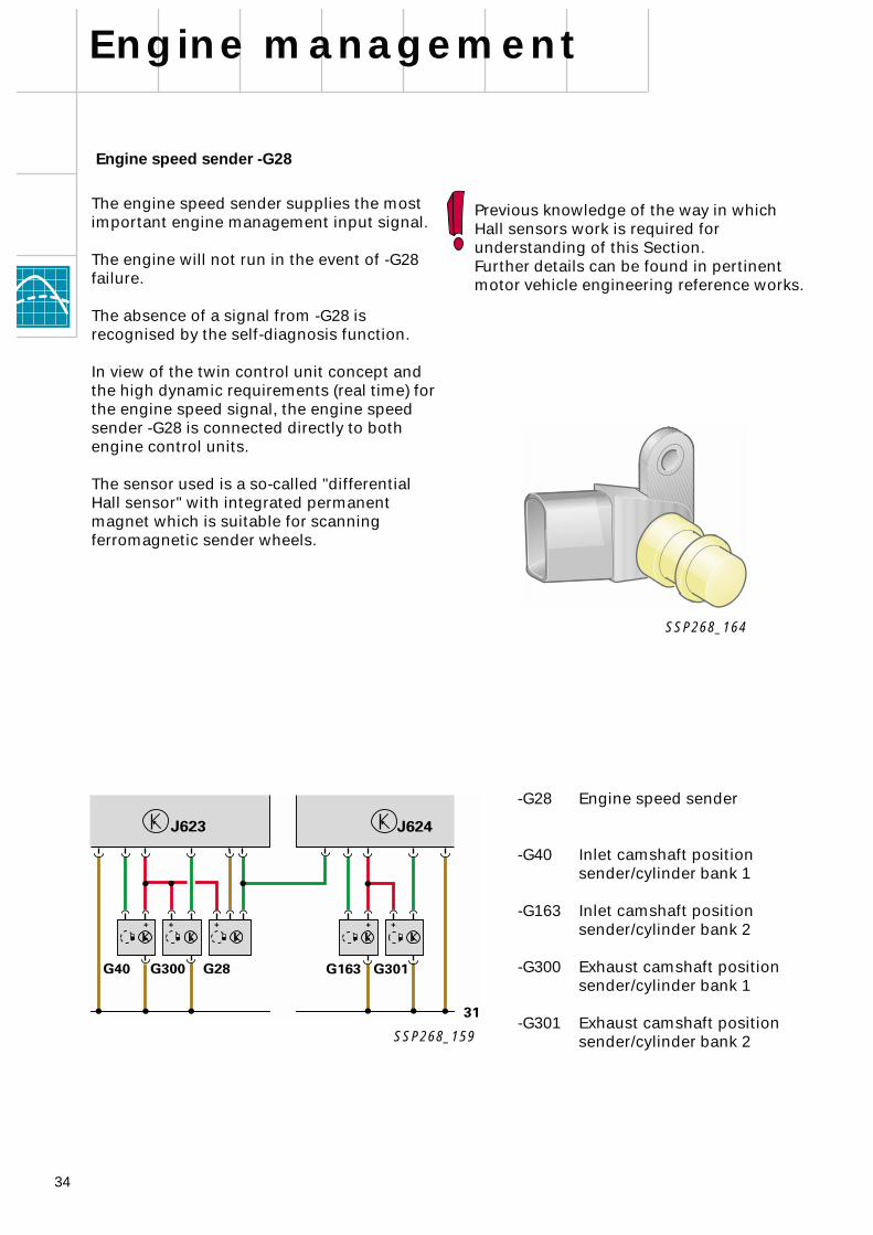
Engine speed sender -G28
The engine speed sender supplies the most important engine management input signal.
The engine will not run in the event of -G28 failure.
The absence of a signal from -G28 is recognised by the self-diagnosis function.
In view of the twin control unit concept and the high dynamic requirements (real time) for the engine speed signal, the engine speed sender -G28 is connected directly to both engine control units.
The sensor used is a so-called "differential Hall sensor" with integrated permanent magnet which is suitable for scanning ferromagnetic sender wheels.
Previous knowledge of the way in which Hall sensors work is required for understanding of this Section. Further details can be found in pertinent motor vehicle engineering reference works.
-G28 Engine speed sender
-G40 Inlet camshaft positionsender/cylinder bank 1
-G163 Inlet camshaft positionsender/cylinder bank 2
-G300 Exhaust camshaft positionsender/cylinder bank 1
-G301 Exhaust camshaft positionsender/cylinder bank 2
Engine management
SSP268_159
SSP268_164

35
SSP268_167
Evaluation electronics
Permanent magnet
Hall element 1 Hall element 2
Engine speed sender -G28
SSP268_168
N
S
Magnetic lines of force
Rotor (sender wheel)
36
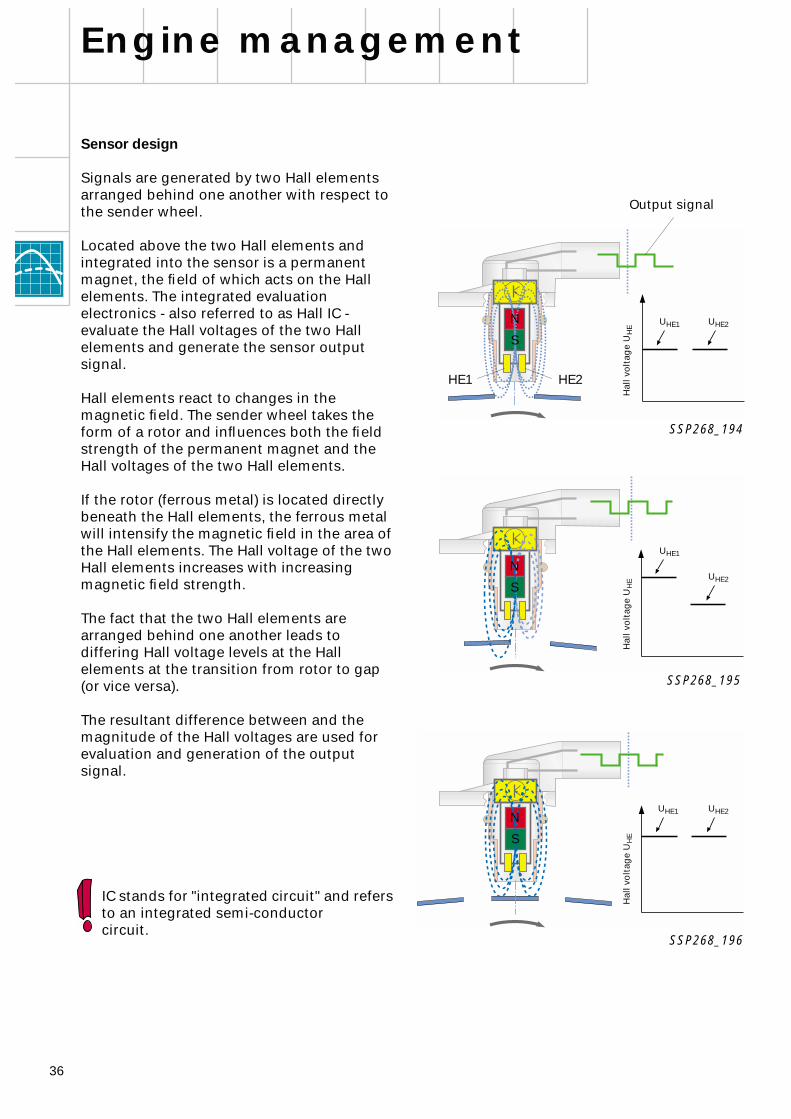
Sensor design
Signals are generated by two Hall elements arranged behind one another with respect to the sender wheel.
Located above the two Hall elements and integrated into the sensor is a permanent magnet, the field of which acts on the Hall elements. The integrated evaluation electronics - also referred to as Hall IC - evaluate the Hall voltages of the two Hall elements and generate the sensor output signal.
Hall elements react to changes in the magnetic field. The sender wheel takes the form of a rotor and influences both the field strength of the permanent magnet and the Hall voltages of the two Hall elements.
If the rotor (ferrous metal) is located directly beneath the Hall elements, the ferrous metal will intensify the magnetic field in the area of the Hall elements. The Hall voltage of the two Hall elements increases with increasing magnetic field strength.
The fact that the two Hall elements are arranged behind one another leads to differing Hall voltage levels at the Hall elements at the transition from rotor to gap (or vice versa).
The resultant difference between and the magnitude of the Hall voltages are used for evaluation and generation of the output signal.
Engine management
IC stands for "integrated circuit" and refers to an integrated semi-conductorcircuit.
SSP268_194
SSP268_195
SSP268_196
U
HE1
U
HE2
Hal
l vo
ltag
e U
HE
U
HE1
U
HE2
Hal
l vo
ltag
e U
HE
U
HE1
U
HE2
Hal
l vo
ltag
e U
HE
N
S
N
S
N
S
Output signal
HE1 HE2
37
–
-G28 and -G40/300
Control and monitoring of camshaft adjustment for cylinder bank 1
–
-G28 and -G163/301
Control and monitoring of camshaft adjustment for cylinder bank 2
There is no camshaft timing control function if one of the camshaft position senders is defective.
In the event of failure of both the camshaft position senders of one bank, engine starting is enabled by the engine run-out detection function.
Adaption of sender signals -G40/-G300/-G163 and -G301 provides more accurate determination of the camshaft basic positions (for more information, refer to SSP 267 - Part 1, Section on "Camshaft timing control", Page 54).
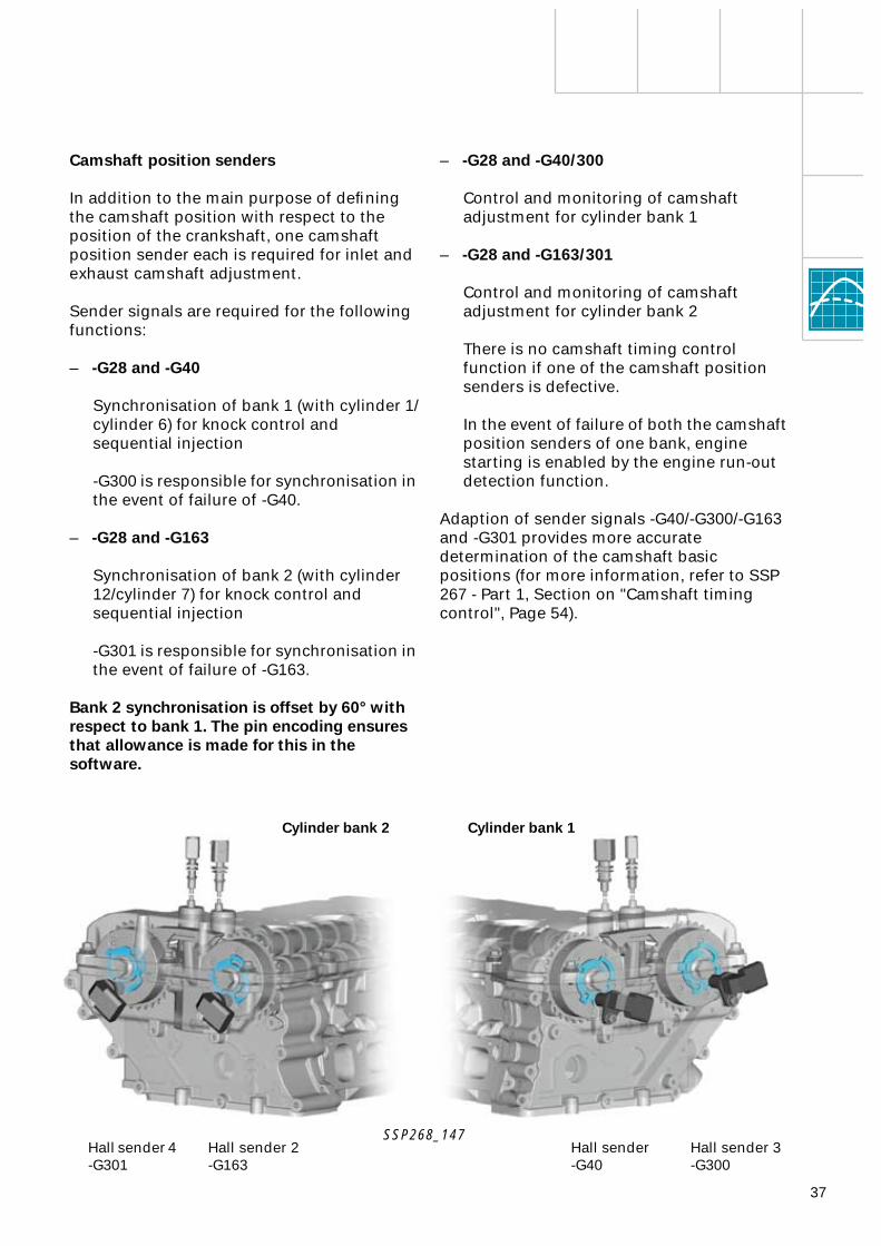
Camshaft position senders
In addition to the main purpose of defining the camshaft position with respect to the position of the crankshaft, one camshaft position sender each is required for inlet and exhaust camshaft adjustment.
Sender signals are required for the following functions:
–
-G28 and -G40
Synchronisation of bank 1 (with cylinder 1/cylinder 6) for knock control and sequential injection
-G300 is responsible for synchronisation in the event of failure of -G40.
–
-G28 and -G163
Synchronisation of bank 2 (with cylinder 12/cylinder 7) for knock control and sequential injection
-G301 is responsible for synchronisation in the event of failure of -G163.
Bank 2 synchronisation is offset by 60° with respect to bank 1. The pin encoding ensures that allowance is made for this in the software.
SSP268_147
Hall sender 4 -G301
Cylinder bank 1Cylinder bank 2
Hall sender 2-G163
Hall sender-G40
Hall sender 3-G300
38
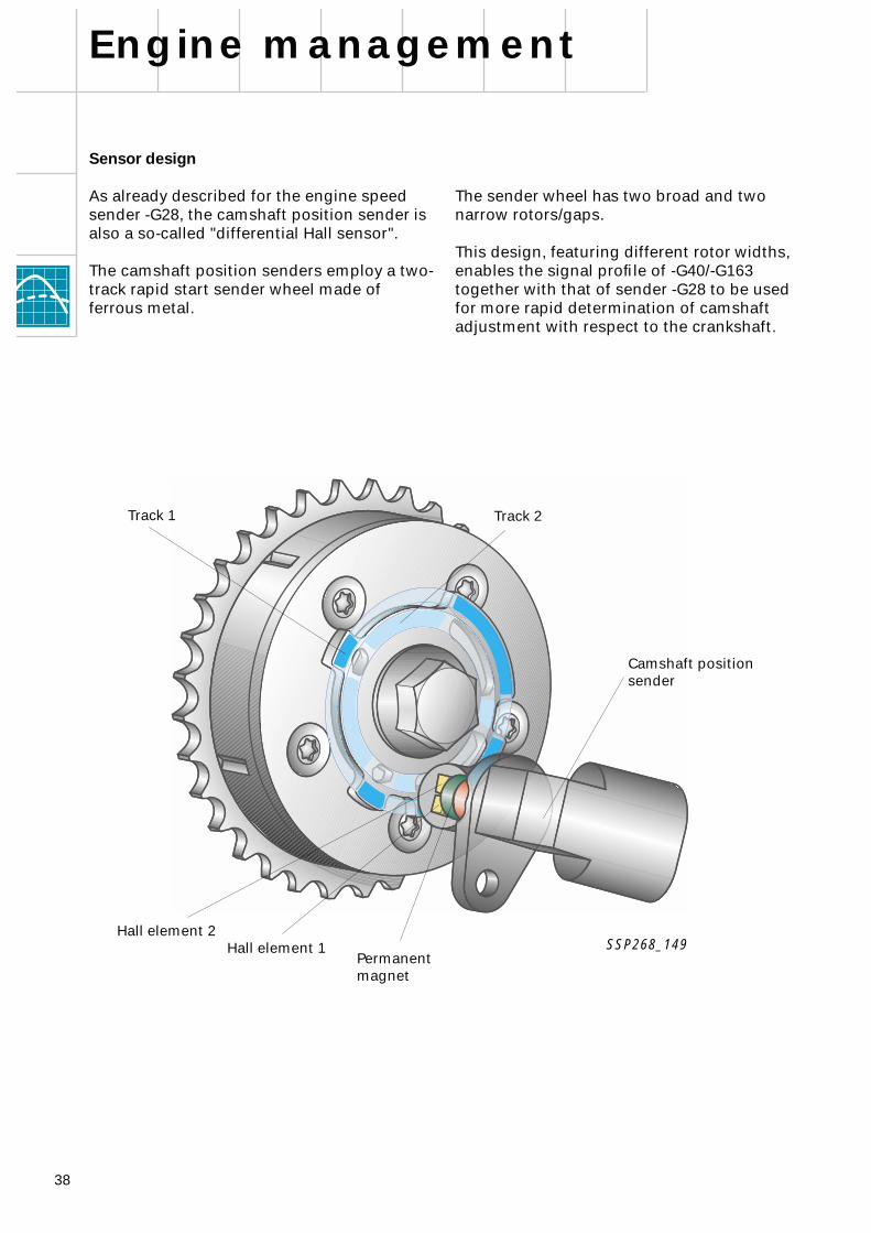
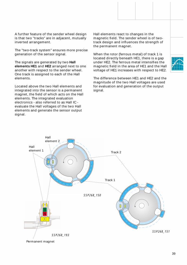
The sender wheel has two broad and two narrow rotors/gaps.
This design, featuring different rotor widths, enables the signal profile of -G40/-G163 together with that of sender -G28 to be used for more rapid determination of camshaft adjustment with respect to the crankshaft.
Sensor design
As already described for the engine speed sender -G28, the camshaft position sender is also a so-called "differential Hall sensor".
The camshaft position senders employ a two-track rapid start sender wheel made of ferrous metal.
Engine management
SSP268_149
Track 1 Track 2
Camshaft position sender
Hall element 1Hall element 2
Permanent magnet
39
Hall elements react to changes in the magnetic field. The sender wheel is of two-track design and influences the strength of the permanent magnet.
When the rotor (ferrous metal) of track 1 is located directly beneath HE1, there is a gap under HE2. The ferrous metal intensifies the magnetic field in the area of HE1 and the Hall voltage of HE1 increases with respect to HE2.
The difference between HE1 and HE2 and the magnitude of the two Hall voltages are used for evaluation and generation of the output signal.
A further feature of the sender wheel design is that two "tracks" are in adjacent, mutually inverted arrangement.
The "two-track system" ensures more precise generation
of the sensor signal.
The signals are generated by two
Hall elements
HE1
and
HE2
arranged next to one another with respect to the sender wheel. One track is assigned to each of the Hall elements.
Located above the two Hall elements and integrated into the sensor is a permanent magnet, the field of which acts on the Hall elements. The integrated evaluation electronics - also referred to as Hall IC - evaluate the Hall voltages of the two Hall elements and generate the sensor output signal.
Permanent magnet
SSP268_151
SSP268_150
SSP268_193
Track 1
Track 2
Hallelement 2
Hallelement 1
NS
40
78°
138°
40°
40°
140°
40°
92°
660°720° 0° 60° 120° 180°
6°
240°
114°
Inle
t ca
msh
aft
-G40
/-G
163
Engine management
CS/Inlet in reference position (retard)
22° maximum advance
CS/Exhaust in reference position (retard)
CS
CS
CS
CS
52° maximum advance
Exh
aust
cam
shaf
t-G
300/
-G30
1
ITDC 9 ITDC 1 ITDC 12 ITDC 5 ITDC 8 ITDC 3
Software reference mark
CS
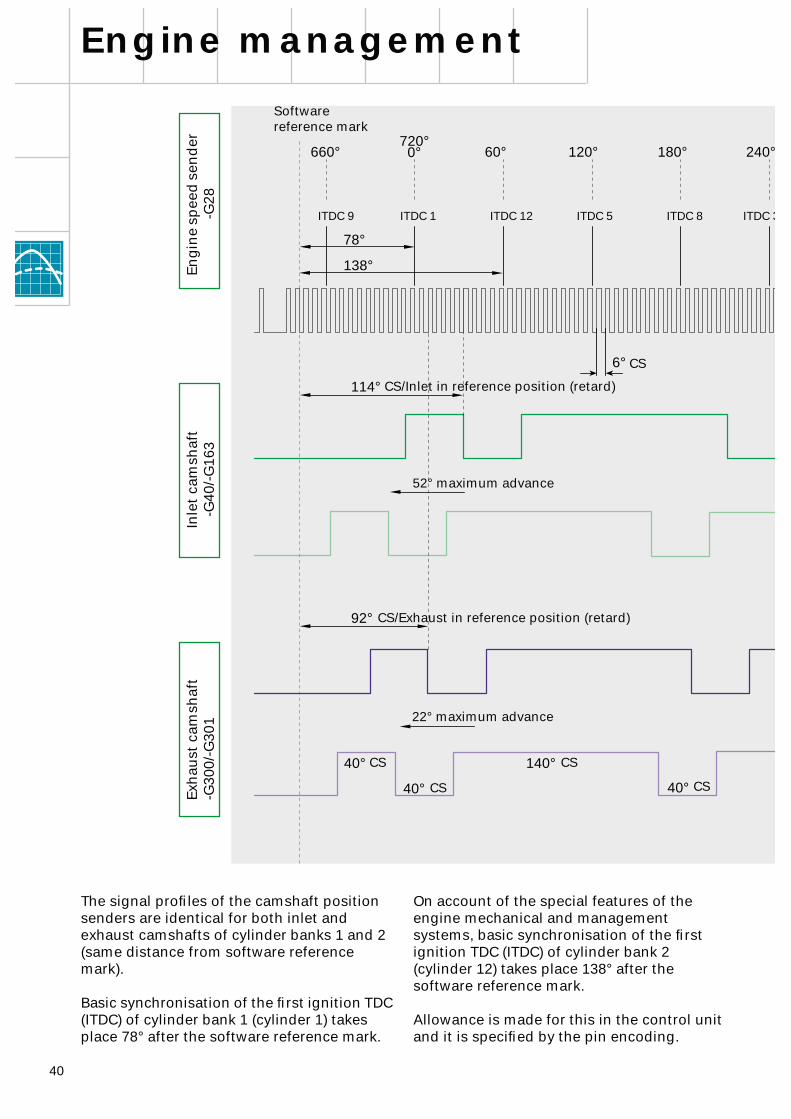
The signal profiles of the camshaft position senders are identical for both inlet and exhaust camshafts of cylinder banks 1 and 2 (same distance from software reference mark).
Basic synchronisation of the first ignition TDC (ITDC) of cylinder bank 1 (cylinder 1) takes place 78° after the software reference mark.
On account of the special features of the engine mechanical and management systems, basic synchronisation of the first ignition TDC (ITDC) of cylinder bank 2 (cylinder 12) takes place 138° after the software reference mark.
Allowance is made for this in the control unit and it is specified by the pin encoding.
Eng
ine
spee
d s
end
er
-G28
41
140°
140°
40°
300° 360° 420° 480° 540° 600°
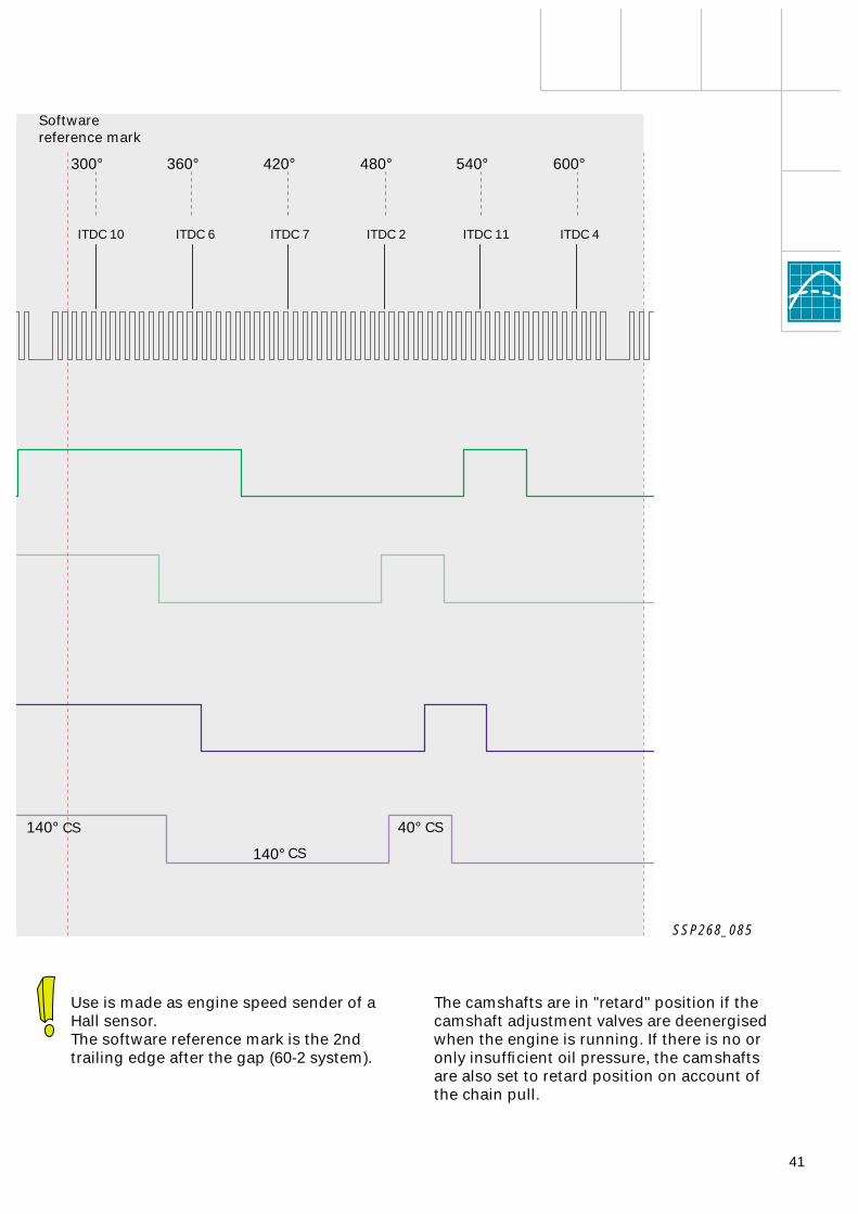
The camshafts are in "retard" position if the camshaft adjustment valves are deenergised when the engine is running. If there is no or only insufficient oil pressure, the camshafts are also set to retard position on account of the chain pull.
SSP268_085
CS
CS
CS
ITDC 4ITDC 11ITDC 2ITDC 7ITDC 6ITDC 10
Software reference mark
Use is made as engine speed sender of aHall sensor.The software reference mark is the 2nd trailing edge after the gap (60-2 system).
42
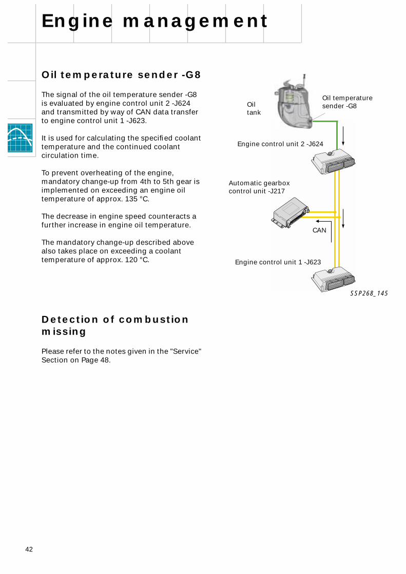
Oil temperature sender -G8
The signal of the oil temperature sender -G8 is evaluated by engine control unit 2 -J624 and transmitted by way of CAN data transfer to engine control unit 1 -J623.
It is used for calculating the specified coolant temperature and the continued coolant circulation time.
To prevent overheating of the engine, mandatory change-up from 4th to 5th gear is implemented on exceeding an engine oil temperature of approx. 135 °C.
The decrease in engine speed counteracts a further increase in engine oil temperature.
The mandatory change-up described above also takes place on exceeding a coolant temperature of approx. 120 °C.
Detection of combustion missing
Please refer to the notes given in the "Service" Section on Page 48.
Engine management
CAN
Automatic gearboxcontrol unit -J217
Oil temperaturesender -G8
Engine control unit 2 -J624
Engine control unit 1 -J623
Oil tank
SSP268_145

43
Notes
44
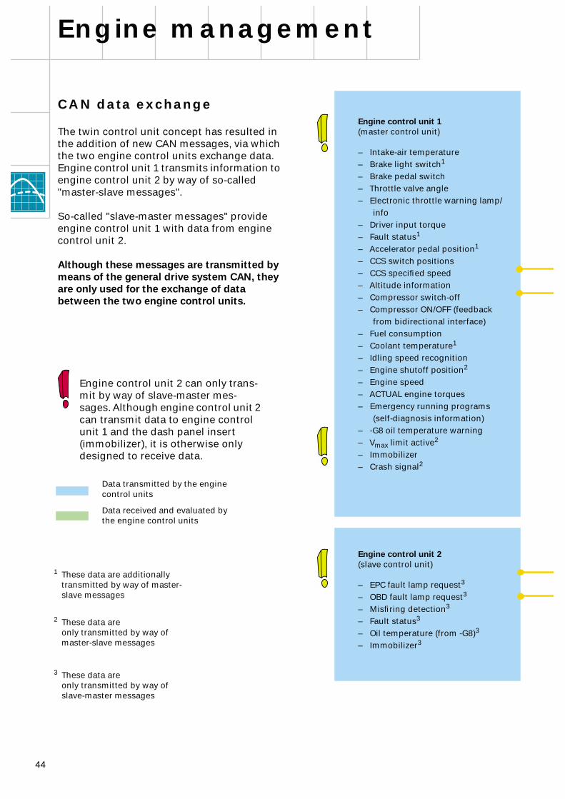
CAN data exchange
The twin control unit concept has resulted in the addition of new CAN messages, via which the two engine control units exchange data.Engine control unit 1 transmits information to engine control unit 2 by way of so-called "master-slave messages".
So-called "slave-master messages" provide engine control unit 1 with data from engine control unit 2.
Although these messages are transmitted by means of the general drive system CAN, they are only used for the exchange of data between the two engine control units.
Engine management
Engine control unit 2 can only trans-mit by way of slave-master mes-sages. Although engine control unit 2 can transmit data to engine control unit 1 and the dash panel insert (immobilizer), it is otherwise only designed to receive data.
Data transmitted by the engine control units
Data received and evaluated by the engine control units
1
These data are additionally transmitted by way of master-slave messages
2
These data are only transmitted by way ofmaster-slave messages
3
These data are only transmitted by way ofslave-master messages
Engine control unit 1
(master control unit)
– Intake-air temperature– Brake light switch
1
– Brake pedal switch– Throttle valve angle– Electronic throttle warning lamp/
info– Driver input torque– Fault status
1
– Accelerator pedal position
1
– CCS switch positions– CCS specified speed– Altitude information– Compressor switch-off– Compressor ON/OFF (feedback
from bidirectional interface)– Fuel consumption– Coolant temperature
1
– Idling speed recognition– Engine shutoff position
2
– Engine speed– ACTUAL engine torques– Emergency running programs
(self-diagnosis information)– -G8 oil temperature warning– V
max
limit active
2
– Immobilizer– Crash signal2
Engine control unit 2(slave control unit)
– EPC fault lamp request3
– OBD fault lamp request3
– Misfiring detection3
– Fault status3
– Oil temperature (from -G8)3
– Immobilizer3
45
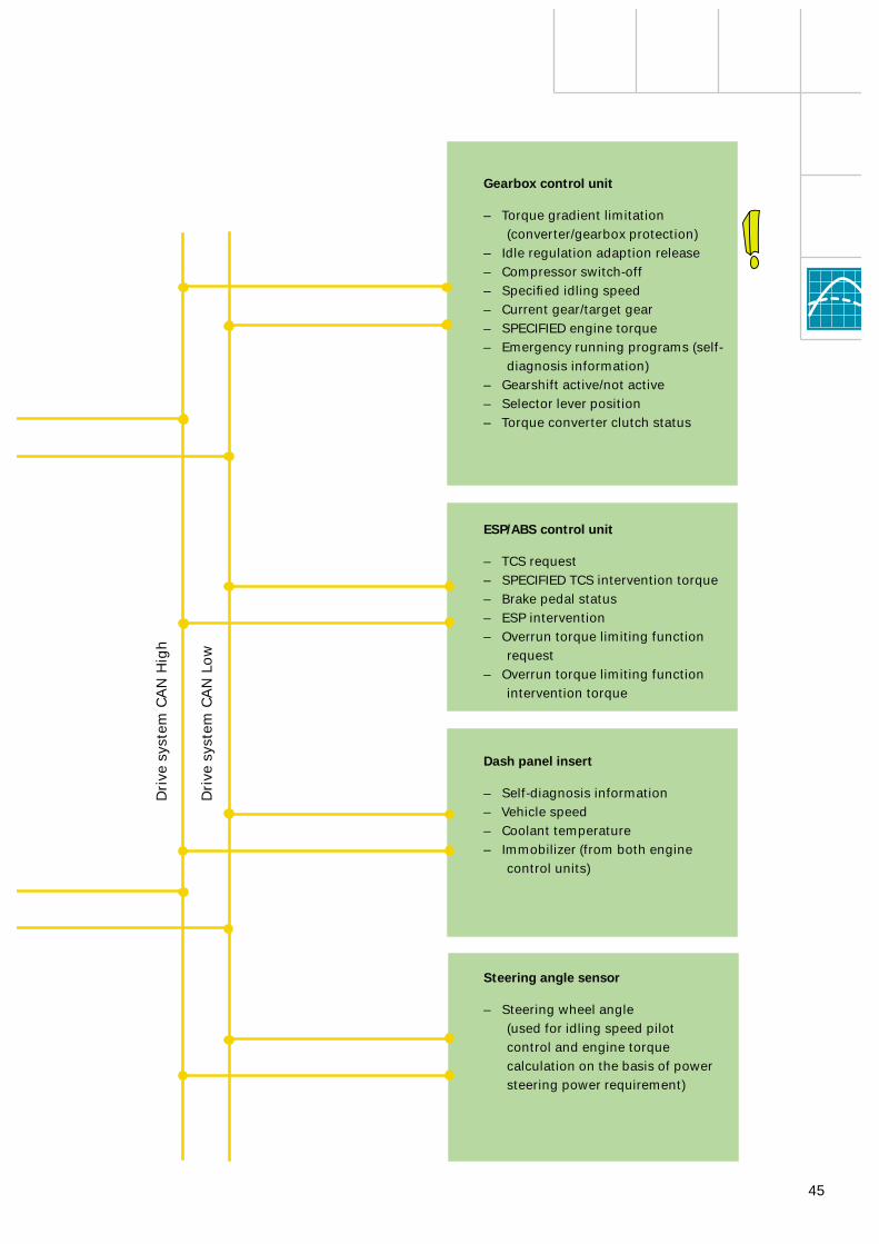
Gearbox control unit
– Torque gradient limitation(converter/gearbox protection)
– Idle regulation adaption release– Compressor switch-off– Specified idling speed– Current gear/target gear– SPECIFIED engine torque– Emergency running programs (self-
diagnosis information)– Gearshift active/not active– Selector lever position– Torque converter clutch status
Steering angle sensor
– Steering wheel angle(used for idling speed pilot control and engine torque calculation on the basis of power steering power requirement)
ESP/ABS control unit
– TCS request– SPECIFIED TCS intervention torque– Brake pedal status– ESP intervention– Overrun torque limiting function
request– Overrun torque limiting function
intervention torque
Dash panel insert
– Self-diagnosis information– Vehicle speed– Coolant temperature– Immobilizer (from both engine
control units)
Dri
ve s
yste
m C
AN
Hig
h
Dri
ve s
yste
m C
AN
Lo
w

46
Engine management
Additional signals/interfaces
In addition to CAN BUS data exchange, the following signals are relayed via separate interfaces.
Pin 42 Terminal 50 ECU* 1 onlyPin 67 Crash signal ECU 1 and ECU 2Pin 41 AC compressor signal ON/OFF ECU 1 and ECU 2Pin 40 AC requirement signal ECU 1 and ECU 2Pin 54 Air-conditioner high-pressure switch signal ECU 1 onlyPin 37 Engine speed signal ECU 1 onlyPin 49 Pin encoding of control units
+ to pin 49 = engine control unit 1- to pin 49 = engine control unit 2
Pin 43 K-wire/diagnosis ECU 1 and ECU 2Pin XX Interfaces - cruise ECU 1 only
control system, refer to Page 47
* ECU = Engine control unit
Terminal 50 signal
The engine run-out detection function (refer to SSP 217, Page 41) can recognise "reversing" in the course of the engine shutoff process. As reversing of the engine can be ruled out on starting, the terminal 50 information (starter operated) is used for checking the plausibility of and evaluating the reversing detection function.
Air-conditioner compressor ON/OFF signal
For a detailed description, refer to SSP 198, Page 59.
The compressor ON signal is also used as a source of information for calculating the speed of the hydraulic fan.
Air-conditioner high-pressure switch signal
The signal from the air-conditioner pressure switch -F129 (high pressure) provides information for actuating the hydraulic fan (refer to Page 8 onwards). When the high-pressure switch is closed (approx. 16 bar), both maximum electric fan speed and maximum hydraulic fan actuation are set.
Crash signal
For a detailed description, refer to SSP 217, Page 47.
Although ECU 1 switches the fuel pump, the crash signal is also transmitted to ECU 2.
In addition to powering the fuel pump, the fuel pump relay is also responsible for supplying voltage to other actuators of both ECUs (refer to block diagram).
The crash signal in ECU 2 suppresses unwanted entries in the fault memory such as would be caused by deactivation of the fuel pump.
As of software version 0004, the crash signal is transmitted by means of a master-slave message. The pin 67 interface is no longer evaluated. To avoid unnecessary expense, no modifications have been made to the wiring harness (wiring to pin 67 interface still exists).
47
01 22a
0,2a
J623
15
57 38 76 75
3 4 6 1 2 5
Air-conditioner requirement signal
For a detailed description, refer to SSP 217, Page 48.
Engine speed signal
For a detailed description, refer to SSP 198, Page 60.
Numerous control units require engine speed information for calculation purposes. In the majority of cases, the engine speed transmitted by way of the CAN message suffices.
The engine speed is one of the most important information parameters for gearbox control, with a high standard of resolution and transmission speed being required.
The output signal (square-wave signal) generated by engine control unit 1 satisfies these requirements.
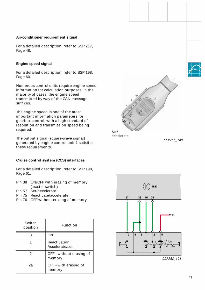
Cruise control system (CCS) interfaces
For a detailed description, refer to SSP 198, Page 61.
Pin 38 ON/OFF with erasing of memory(master switch)
Pin 57 Set/deceleratePin 75 Reactivate/acceleratePin 76 OFF without erasing of memory
SSP268_189
SSP268_191
Switch position Function
0 ON
1 Reactivation Accelerate/set
2 OFF - without erasing of memory
2a OFF - with erasing of memory
FIXACTIV
ON
OFF
1
0
2a
Set/decelerate
48
The readiness code must be set, read out and reset separately for each control unit (e.g. by starting "short trip" test sequence with diagnostic tester).
Erasing the fault memory sets the readiness code automatically in the appropriate control unit.
The combustion missing detection function is only activated in engine control unit 2 -J624, which is thus responsible for both cylinder banks.
Combustion missing affecting cylinder bank 1 can only be read out in engine control unit 2.
Notes on maintenance
A few special points have to be noted as regards handling of diagnostic testers and the self-diagnosis function on account of the twin control unit concept.
As regards self-diagnosis, the two control units are basically to be viewed as separate entities (does not apply to combustion missing detection).
The self-diagnosis functions are implemented in the control unit to which the components are connected (with the exception of combustion missing detection).
Service
Separate address words are required for entry into self-diagnosis function:
Address word 01 Engine control unit 1 -J623Cylinder bank 1(exhaust banks 1 and 2)
Address word 11 Engine control unit 2 -J624Cylinder bank 2(exhaust banks 3 and 4)
If a fault has been stored in engine control unit 2, the fault "Please read out fault memory of engine control unit 2" will be stored in engine control unit 1. This fault message can only be erased when there is no fault entry stored in engine control unit 2.
Both control units must …
… have the same software version… be matched to the cruise control system
(CCS)… be matched to the immobilizer… be viewed as separate entities for
self-diagnosis… have the same encoding
For more details of Euro On-Board Diagnosis (EOBD) and readiness code,refer to SSP 231.
Further information on the twin control unit concept can be found on Page 26 onwards.
For defined fault-finding, the Lambda control can be deactivated under "Basic setting" on selecting display group 99/reactivated under "Reading measured value block".
49
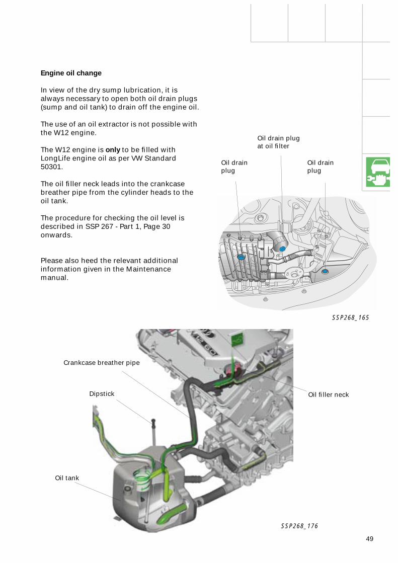
Engine oil change
In view of the dry sump lubrication, it is always necessary to open both oil drain plugs (sump and oil tank) to drain off the engine oil.
The use of an oil extractor is not possible with the W12 engine.
The W12 engine is only to be filled with LongLife engine oil as per VW Standard 50301.
The oil filler neck leads into the crankcase breather pipe from the cylinder heads to the oil tank.
The procedure for checking the oil level is described in SSP 267 - Part 1, Page 30 onwards.
Please also heed the relevant additionalinformation given in the Maintenance manual.
SSP268_176
SSP268_165
Oil drainplug
Oil filler neck
Crankcase breather pipe
Dipstick
Oil tank
Oil drainplug
Oil drain plugat oil filter

50
Service
Workshop equipment/special tools
Listed in the following are the new items of workshop equipment and special tools designed for the W12 engine.
VAS 6100 Workshop crane
With a loadbearing capacity of 1200 kg, the workshop crane VAS 6100 is designed to handle the new large-volume engines (e.g. V8 TDI, W12) as well as future developments.
Extension VAS 6101 (load bearing capacity 300 kg) is available as an option.
VAS 6095 Engine and gearbox assembly mount
In addition to the generously designed loadbearing capacity of 600 kg, VAS 6095 offers two major new features.
Unit mounting with the aid of universally adjustable clamps in combination with the locating pins provides ease of access to the back of the engine (e.g. when working on timing mechanism).
Work is facilitated by being able to hydraulically adjust the height of the unit by approx. 200 mm.
The tilt mechanism enables the unit to be easily moved into any angular position required. The mechanism is self-locking so that there is no need for separate fixing.
The integrated storage facilities and sliding drip tray for collecting fluids round off the practical design of this item.
VAS 6095 is compatible with existing engine and gearbox supports.
Locating pin
SSP268_186
SSP268_184
SSP268_182
51
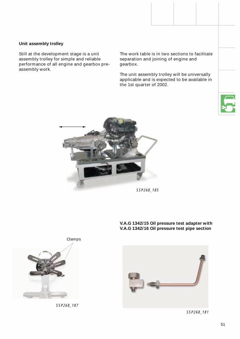
Unit assembly trolley
Still at the development stage is a unit assembly trolley for simple and reliable performance of all engine and gearbox pre-assembly work.
The work table is in two sections to facilitate separation and joining of engine and gearbox.
The unit assembly trolley will be universally applicable and is expected to be available in the 1st quarter of 2002.
V.A.G 1342/15 Oil pressure test adapter with V.A.G 1342/16 Oil pressure test pipe section
Clamps
SSP268_185
SSP268_181
SSP268_187

Service.
For internal use only
All rights reserved. Subject to technical modification.AUDI AGDepartment I/VK-35D-85045 IngolstadtFax 0841/89-36367140.2810.87.20Technical status as at 11/01Printed in Germany
The 6.0 l W12 enginein the Audi A8 - Part 2
Self-study programme 268
268
268
Top Related