


Languages
Pages
Legal


Introduction to the
Conventional Gait Model
Richard Baker
Professor of Clinical Gait Analysis
Blog: wwRichard.net
1

Conventional Gait Model
Newington, Davis,Gage
Helen Hayes, Kadaba
Vicon Clinical Manager (VCM), Plugin Gait
Conventional gait model (Visual 3d)
2
Conventional Gait Model
By far the most widely used and best
understood model in clinical gait analysis.
Widely used in more general applications.
Better validated than any other model.
Better standardised than any other model.
3

What is a model4
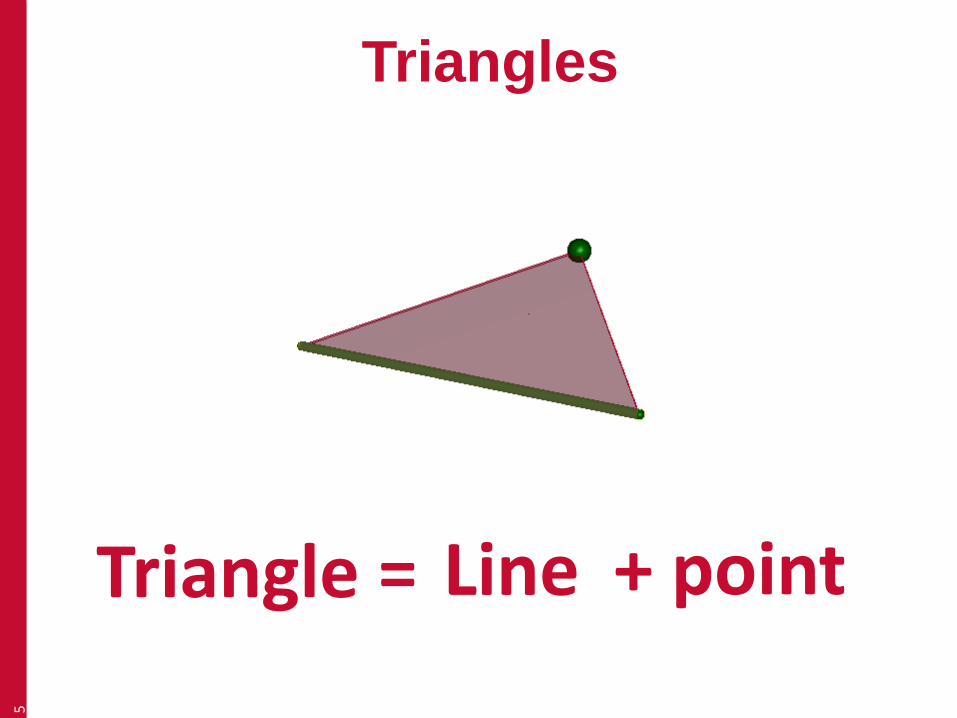
Triangles5
LineTriangle = + point
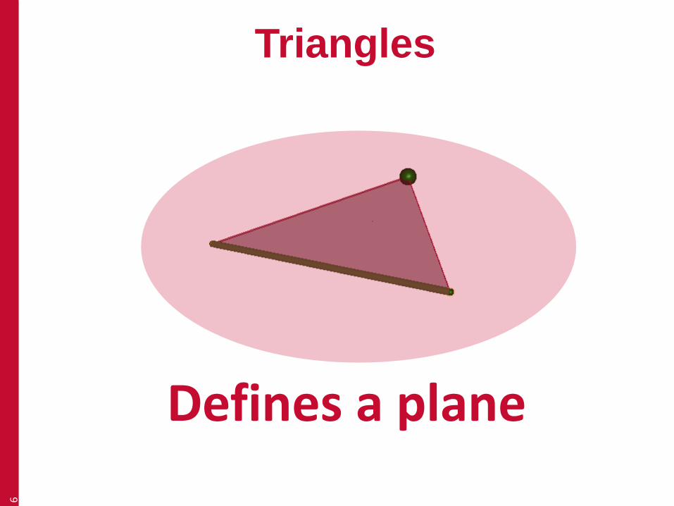
Triangles6
Defines a plane
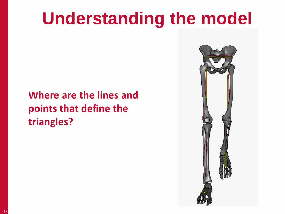
Understanding the model7
Where are the lines and points that define the triangles?
Understanding the model
• Anatomical segment definition
• Theory of marker placement
• Placing markers on the ideal person
• Placing markers on less ideal people.
8

Anatomical segment
definition
9

Femur10
Principal axis From hip joint centre to knee joint centre
Reference pointLateral epicondyle

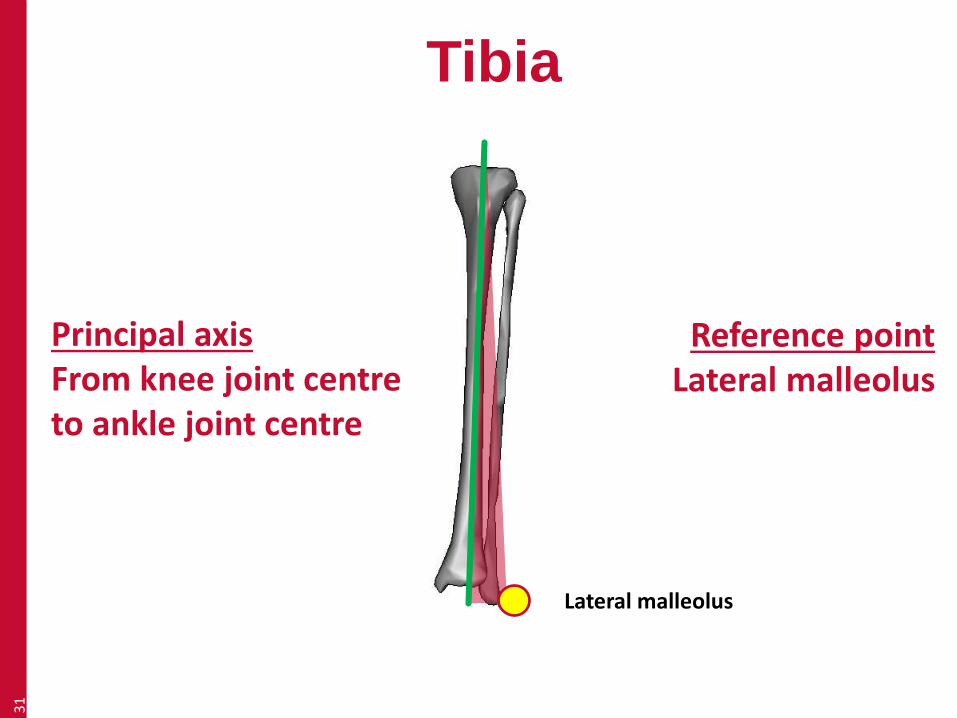
Tibia11
Principal axis From knee joint centre to ankle joint centre
Reference pointLateral malleolus

Pelvis12
Principal axis From one ASIS to the other
Reference pointMid point of PSIS

Foot13
Principal axis Along long axis of foot

Foot14
Principal axis Along long axis of foot

Theory of marker placement
(Ideal person)
15

Marker placement
• The system only sees the middle of the
marker (not the baseplate)
• Use landmarks as a guide and try and
visualise the lines and planes
• Always place markers on skin
16
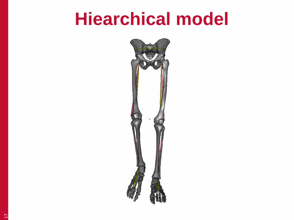
Hiearchical model17

Pelvis18
Principal axis From one ASIS to the other
Reference pointMid point of PSIS
Right ASIS (Anterior superior iliac spine)
Left ASIS

Pelvis19
Principal axis From one ASIS to the other
Reference pointMid point of PSIS
Left PSIS (Posterior superior
iliac spine)
Right PSIS

Pelvis20
Principal axis From one ASIS to the other
Reference pointMid point of PSIS
Marker centres are a marker radius in front of ASIS
Need to tell software what the marker diameter is
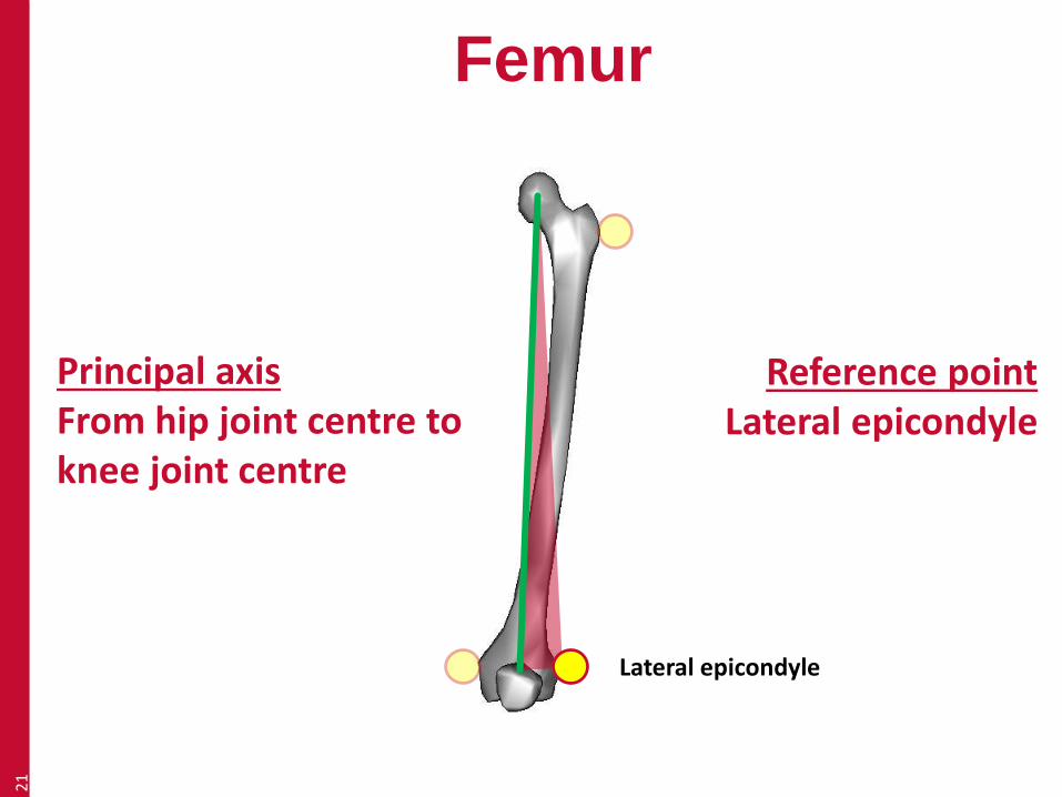
Femur21
Principal axis From hip joint centre to knee joint centre
Reference pointLateral epicondyle
Lateral epicondyle

Femur22
Femoral head (femur) and cetnre of acetabulum (pelvis) are in same place.
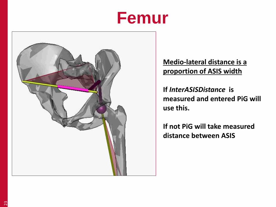
Femur23
Medio-lateral distance is a proportion of ASIS width
If InterASISDistance is measured and entered PiG will use this.
If not PiG will take measured distance between ASIS

Femur24
Anterior-posterio distance
If AsisTrocDist is entered then PiG will calculate a distance based on this and leg length.
If not the distance is calculated as a function of leg length only
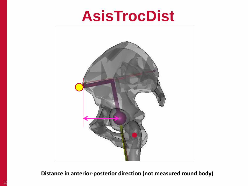
AsisTrocDist25
Distance in anterior-posterior direction (not measured round body)
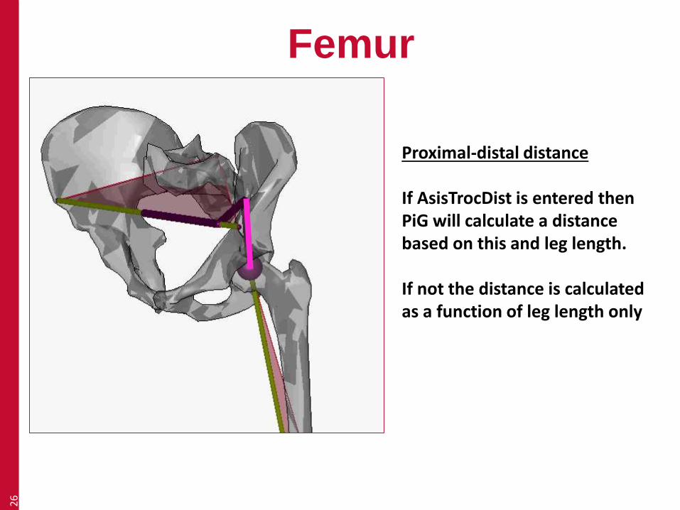
Femur26
Proximal-distal distance
If AsisTrocDist is entered then PiG will calculate a distance based on this and leg length.
If not the distance is calculated as a function of leg length only
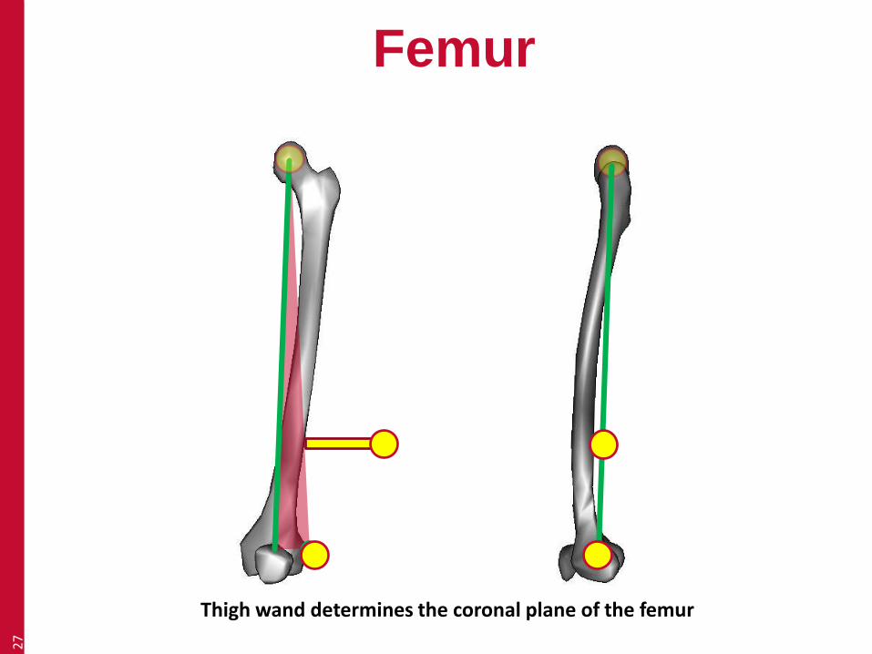
Femur27
Thigh wand determines the coronal plane of the femur
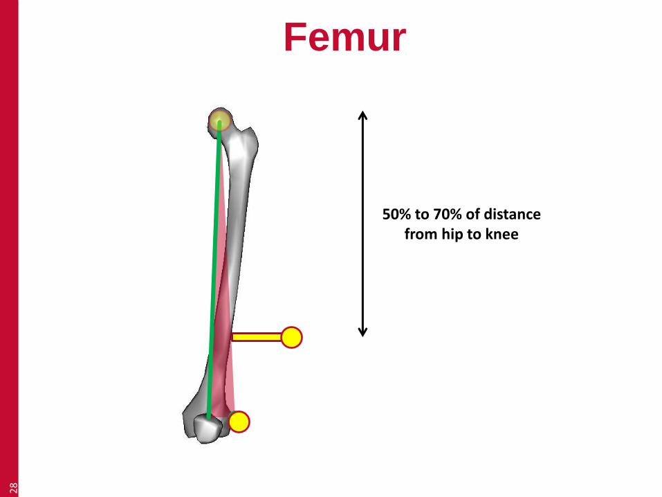
Femur28
50% to 70% of distance from hip to knee

AsisTrocDist29
Distance in anterior-posterior direction (not measured round body)

AsisTrocDist30
Distance in anterior-posterior direction (not measured round body)
Tibia31
Principal axis From knee joint centre to ankle joint centre
Reference pointLateral malleolus
Lateral malleolus
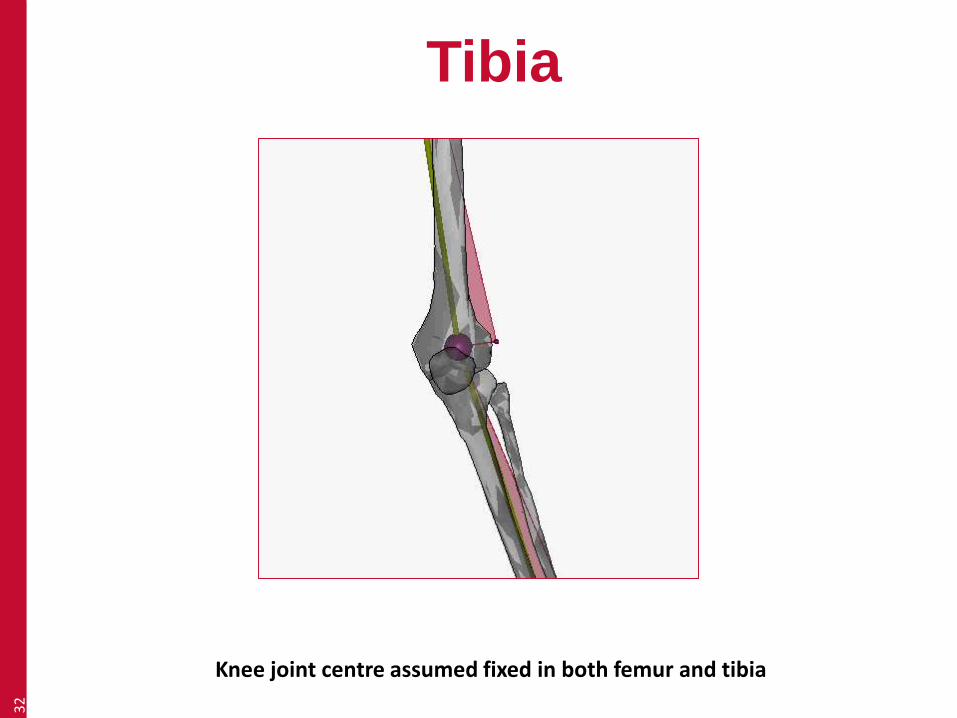
Tibia32
Knee joint centre assumed fixed in both femur and tibia
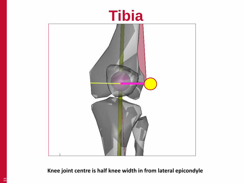
Tibia33
Knee joint centre is half knee width in from lateral epicondyle
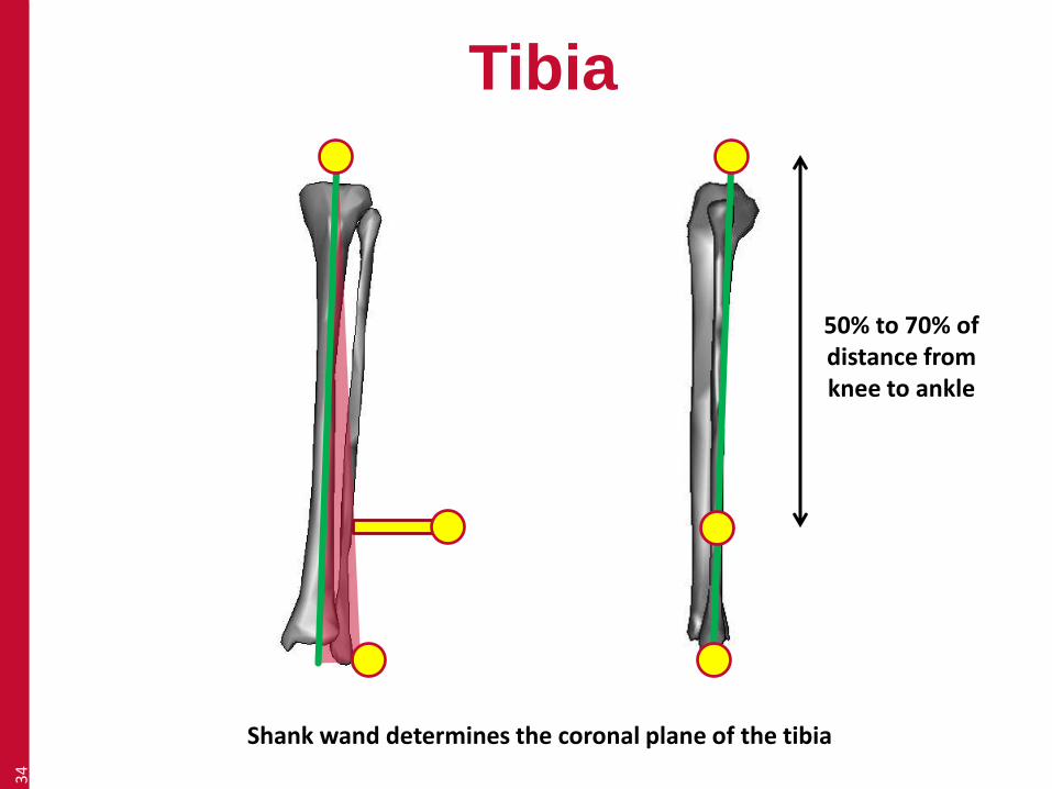
Tibia34
Shank wand determines the coronal plane of the tibia
50% to 70% of distance from knee to ankle
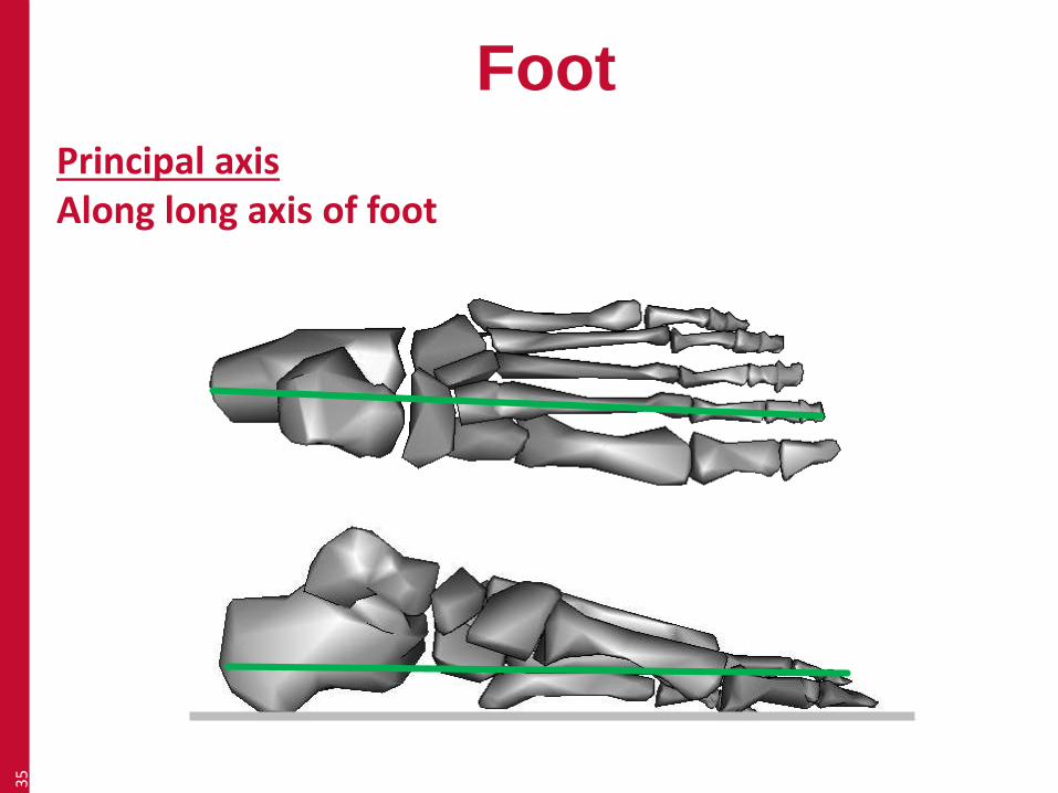
Foot35
Principal axis Along long axis of foot

Foot36

Foot37
Knee joint centre is half knee width in from lateral epicondyle
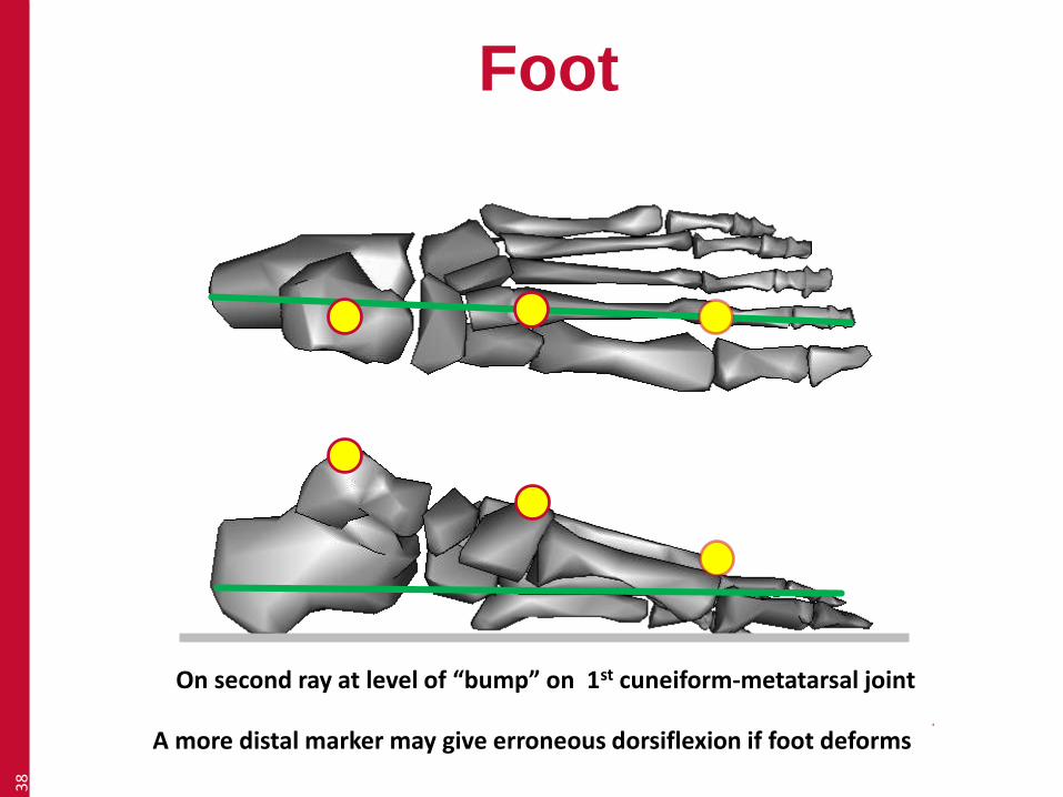
Foot38
On second ray at level of “bump” on 1st cuneiform-metatarsal joint
A more distal marker may give erroneous dorsiflexion if foot deforms
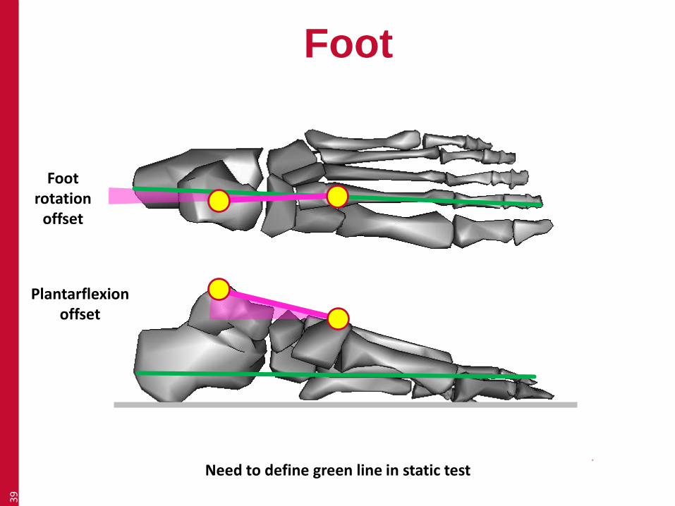
Foot39
Foot rotation
offset
Plantarflexion offset
Need to define green line in static test

Foot40
Foot rotation
offset
Plantarflexion offset
Line from heel to forefoot markers defines long axis of foot in horixontal plane

Foot41
Foot rotation
offset
Plantarflexion offset
Line from heel to forefoot markers defines long axis of in sagittal plane
(or check foot flat box)

Foot42
If foot not flat on the ground heel marker must be same distance from plantar surface as forefoot marker
Plantarflexion offset

Placing markers on less
ideal people
43

Pelvis44
Must enter AsisTrocDist
Must still palpate landmarks
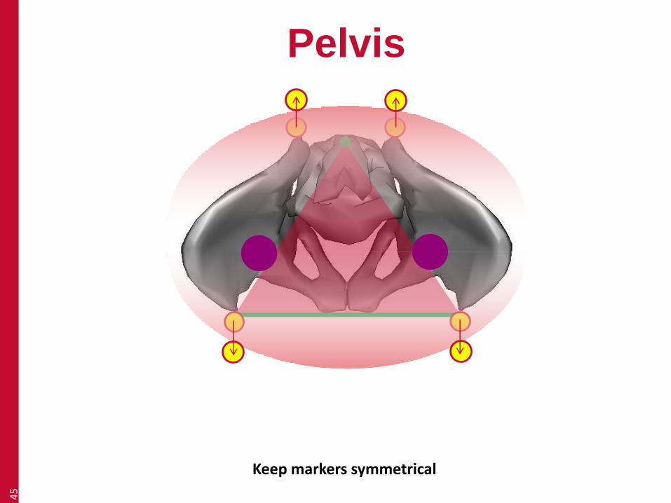
Pelvis45
Keep markers symmetrical
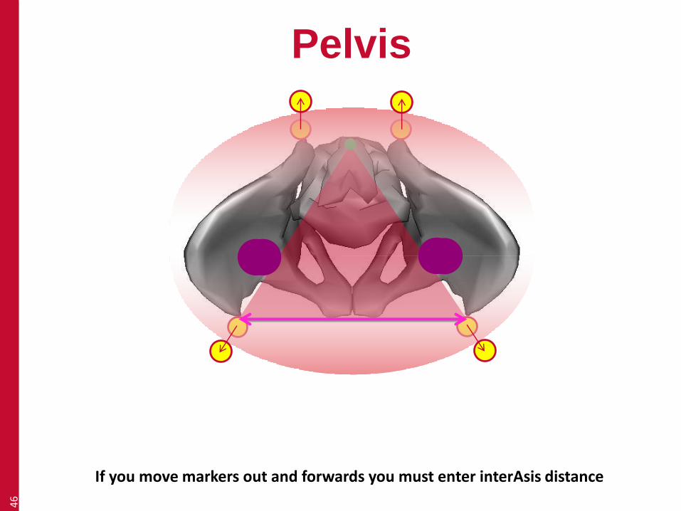
Pelvis46
If you move markers out and forwards you must enter interAsis distance

Thanks for listening
Richard Baker
Professor of Clinical Gait Analysis
Blog: wwRichard.net
47
Top Related