


Languages
Pages
Legal


11 1
11
1

33
2

33 3
33
3
Air Insulated Switchgear (AIS) by L&T is used for control and protection of electrical distribution in any industry, utility or residential area. The AIS cubicle has Vacuum Circuit Breakers (VCB) as the switching device and the control can be off ered through numerical or electromechanical relays.
The VCB and switchboard complies to the latest international standard. The VCB is type tested in accordance to IEC 62271-100, whereas the cubicle is type tested as per IEC62271-200. Further to meet stringent safety norms, the cubicle is subjected to internal arc test at 40kA, 1 sec.
All operations are behind closed door thus enhancing the safety of operating personnel.
The AIS panel is available from 3.3kV upto 36kV and for current ratings upto 3150A with natural cooling. The short circuit rating available is upto 50kA for 3 sec. To prove its suitability for service in severe climatic conditions, the switchgear has been subjected to climatic aging tests according to IEC 60932, and proven to Design Class 2 (the highest class). The switchgear has been designed and tested to ensure the safety of the operator in the event of an internal-arc fault. Arc vents are provided in the busbar, cable and VCB compartments.
The switchgear has also been successfully tested to withstand seismic forces of 5-7 on the Richter scale, in accordance with IEC 60068-3-3.
• Metalclad, fully compartmentalized
• Horizontal isolation, horizontal drawout
• Fully insulated design
• Internal arc fault-proven
• All operations behind closed doors
• Interlocked for safety
KEY FEATURES• Fully rated fault-make earthing switch
• Earthquake-proven
• Simple installation
• Readily extensible
• Minimal maintenance

44
44
4
5
Made of high-grade pickled-&-oiled mild steel sheets,
cut and folded on numerically controlled machines,
the cubicle parts are painted by an advanced Cathodic
Electro-Deposition (CED) process which provides
optimum protection against corrosion and weathering.
The paintwork is tested to withstand 1000 hours in a
5% salt spray.
The cubicle parts are riveted/bolted together to
form a rigid enclosure with fully segregated busbar
compartment, circuit compartment, VCB compartment
and low voltage compartment. The construction
complies fully with the requirements of a metal-clad
enclosure as defi ned in IEC62271-200.
Standard ingress protection is IP4X as per IEC 60529.
Higher IP ratings are available on request.
The bus bar chamber consists of the main busbar system. The bus
bars are provided with insulation along its complete length and the
joints are provided with removable shrouds.
Since all parts of the bus bar system are well insulated, the safety
of the device as a whole and of operating personnel is enhanced.
CUBICLE
BUSBAR CHAMBER
12kV - SINGLE BUSBAR
The 12kV Single busbar design is a fully compartmentalized metal clad design. This design is suitable for 3.3kV, 6.6kV &
12kV. The diff erent parts of this design are described below.

4
55 5
55
5
VCB CHAMBER
The VCB chamber houses the VCB truck. The movement of the
VCB truck is interlocked with the VCB and the VCB door to provide
complete safety.
Automatic metal shutters are provided to prevent access to live
parts when the VCB is isolated or withdrawn. These metallic
shutters are spring operated and the mechanism is, in turn, linked
to the movement of the circuit breaker truck. This mechanism is
more reliable than gravity operated shutters. The shutters can be
padlocked independently.
The VCB compartment is fi tted with a padlockable front door which
not only provides a fl ush frontage to the switchboard line-up, but
also upholds the integrity of the ingress protection (IP) rating even
when the VCB is isolated or withdrawn. The operation of the VCB
and the earthing switch can be carried out with the door closed.
The following interlocks are provided in the panel:
• All operations are behind closed door.
• VCB cannot be engaged or withdrawn unless it is in open
position.
• VCB cannot be operated unless it is in the engaged or in test
position.
• Earthing switch cannot be closed when the VCB is engaged.
• VCB cannot be engaged when the earthing switch is closed.
• Rear door interlock (Optional): The rear door cannot be opened
unless the breaker is in test position and the earthing switch is
closed.
• VCB cannot be racked in unless the plug is fi tted.
Any other interlock can be provided as per requirement.

66
66
6
7
VACUUM CIRCUIT BREAKER
At the heart of the switchgear is the vacuum circuit breaker. The VCB is truck-mounted, and adopts the proven horizontal isolation / horizontal drawout principle. The VCB is tested as per the latest international standard IEC62271-100.
The trend in the interrupter design is to continuously reduce the vacuum envelope size and enhance short circuit capability at the same time. Our VCB designs are continuously reviewed and upgraded to keep up with the latest developments in vacuum technology.
Two options of operating mechanisms are off ered:
• Hand-charged spring, stored energy mechanism with manual and/or electrical release• Motor-charged spring, stored energy mechanism with manual and electrical release
The VCB mechanism requires minimal maintenance. Its design lifespan is 20 years or 10,000 operations.
VACUUM CONTACTORS
For specifi c application of motor switching, vacuum
contactors are off ered. These Vacuum contactors are
available upto 6.6kV with current rating of 400A and short
circuit level upto 50kA. Vacuum contactors are fi tted with HT
fuses for short circuit protection.

6
77 7
77
7
LOW VOLTAGE COMPARTMENT
The dimensions provided off er ample space for mounting of terminals, fuses, MCB, relays. meters etc. for any standard
scheme. An additional chamber can be mounted on top, if necessary, for more complex protection and control schemes.
Wire bunches are routed through horizontal and vertical wire ways which provide support and order.
CABLE CHAMBER
No live parts are located less than 300mm above fl oor level.
The cable termination height is more than 750mm above fl oor level,
and generous space is provided for terminating the power cable. This
ensures a higher bending radius as well as reduces tension on terminals.
The cable chamber also houses the CT and the earthing switch.

88
88
8
9
OTHER AUXILIARIES
CURRENT TRANSFORMERS
Current transformers can be mounted in the cable chamber of the panel.
While wound type and ring type of CTs are in popular usage and can be
off ered, we recommend using bushing type CTs. These CTs are mounted
on earthed condenser bushings. This mounting arrangement ensures
higher degree of safety. Current transformers are supplied by reputed
manufacturers with expertise in CT design.
POTENTIAL TRANSFORMERS
Potential Transformers are usually mounted on the rear of the cubicle, in the
upper part of the circuit compartment. The PTs are fuse protected on both
primary and secondary sides. We can also off er front draw-out VTs.
Three mounting options are off ered: fi xed, isolatable and drawout. The
isolatable design off ers the advantages of isolation without having to put
up with the inconvenience of a conventional drawout PT.
EARTHING SWITCH
Circuit earthing is eff ected by a fault-make earthing switch
interlocked with the VCB. The switch is tested to make
and carry the rated short-circuit current for 3 seconds, in
accordance with latest IEC standards. Earthing by means
of an integral earthing switch is proven to be safe, simple
and reliable.
Busbar earthing is eff ected by a busbar earthing switch
usually mounted at the bus-section panel. Option of cable
earthing and bus earthing trucks are also available.
8
99 9
99
9
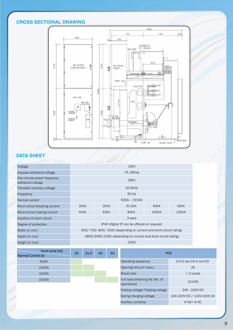
CROSS SECTIONAL DRAWING
Voltage
Impulse withstand voltageOne minute power frequency withstand voltageTransient recovery voltage
Frequency
Normal current
Short circuit breaking current
Short circuit making current
Duration of short circuit
Degree of protection
Width (in mm)
Depth (in mm)
Height (in mm)
25 31.5 40 50
630A
1250A
2000A
3150A
24V - 220V DC
24V-220V DC / 110V-230V AC
6 NO+ 6 NC
Closing voltage/Tripping voltage
Spring charging voltage
Auxiliary contacts
VCB
1805/2065/2160 (depending on current and short circuit rating)
3 secs
630A – 3150A
Full load switching life (No. of operations)
10,000
O-0.3 sec-CO-3 min-CO
35
< 3 cycles
Operating sequence
Opening time (in msec)
Break time
80kA
20kA 25kA 31.5kA
2300
50kA
125kA
IP4X (Higher IP can be offered on request)
600/ 700/ 800/ 1000 (depending on current and short circuit rating)
50kA 63kA
40kA
100kA
12kV
75, 95kVp
28kV
20.6kVp
50 Hz
Fault Level (kA)Normal Current (A)
DATA SHEET

1010
1010
10
11
36KV - SINGLE BUSBAR
10
The PT is mounted on the rear of panel and is a special execution. It is an
isolatable type of arrangement with a swing out fuse assembly. The PT
does not have to be withdrawn completely for replacement of fuse or for
isolation purpose. By means of a lever, the fuses can be easily accessed
and replaced. This reduces the maintenance time.
This switchboard has 4 chambers:
1. Busbar chamber: The bus bars in this switchboard are circular in shape. They are completely insulated and the joints
are provided with shrouds.
2. VCB chamber: The VCB chamber houses the VCB truck. It has spring operated safety shutters and padlockable front
door. Interlocks are provided to ensure complete safety of operating personnel.
3. Cable chamber: The cable chamber has a liberal volume for ease of cable termination.
4. Low voltage compartment: The low voltage compartment has a generous space for mounting relays and meters.
The 36kV AIS panel off ered is similar in features to the 12kV AIS panel. The 36kV AIS panel is a fully compartmentalised
metal clad design. The switchboard has all protective features of the 12kV panel including all the safety interlocks, integral
earth switch, complete insulation etc. The switchboard is type tested as per the latest international design and is very easy
to operate and maintain.
10
1111 11
1111
11
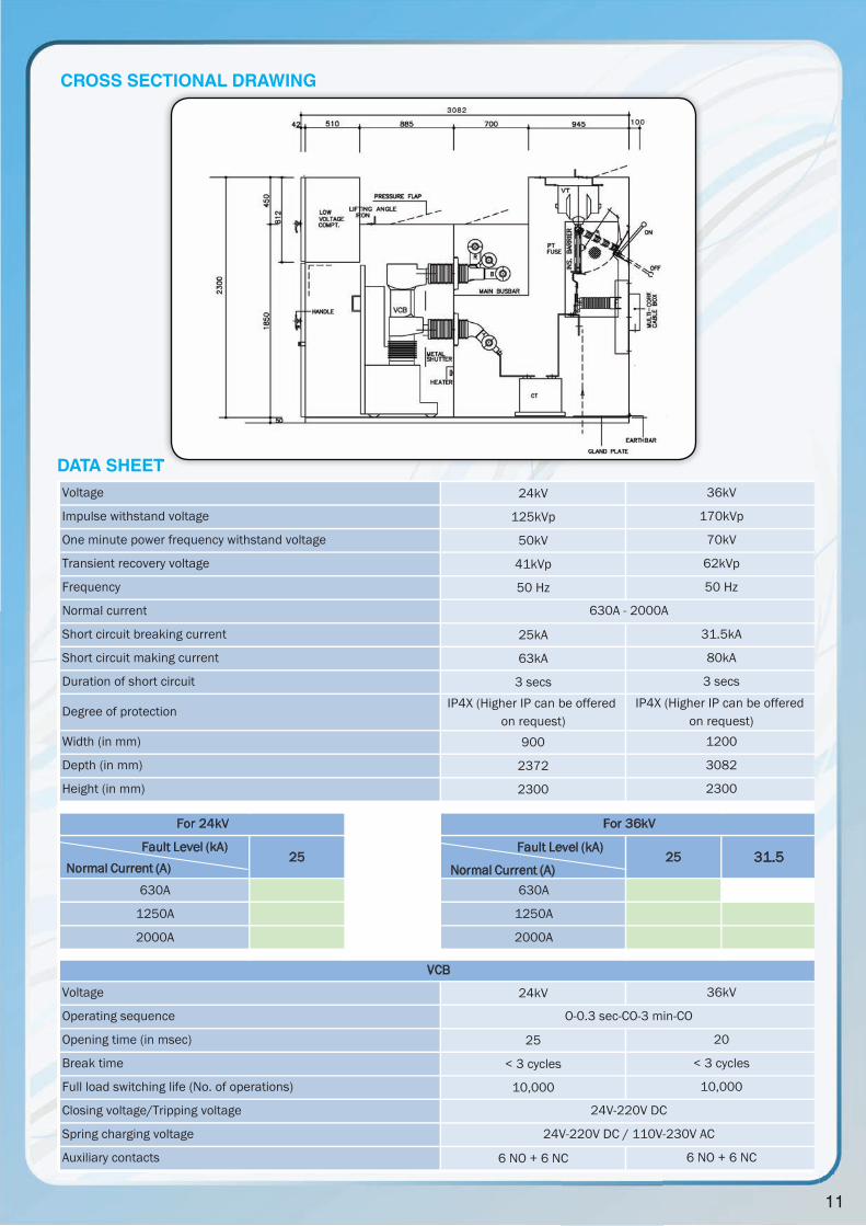
24kV
125kVp
50kV
41kVp
50 Hz
25kA
63kA
3 secs IP4X (Higher IP can be offered
on request)900
2372
2300
25 25 31.5
630A 630A
1250A 1250A
2000A 2000A
24kV
25
< 3 cycles
10,000
6 NO + 6 NC
< 3 cycles
10,000
24V-220V DC
24V-220V DC / 110V-230V AC
Normal current
For 24kV
Short circuit breaking current
Short circuit making current
Duration of short circuit
Degree of protection
Width (in mm)
Depth (in mm)
Height (in mm)
Closing voltage/Tripping voltage
Spring charging voltage
36kV
O-0.3 sec-CO-3 min-CO
20
One minute power frequency withstand voltage
Voltage
Impulse withstand voltage
Transient recovery voltage
Frequency
630A - 2000A
6 NO + 6 NC
For 36kV
36kV
170kVp
62kVp
70kV
50 Hz
31.5kA
80kA
3 secs
IP4X (Higher IP can be offered on request)
1200
3082
2300
VCB
Auxiliary contacts
Voltage
Operating sequence
Opening time (in msec)
Break time
Full load switching life (No. of operations)
Fault Level (kA)
Normal Current (A)
Fault Level (kA)Normal Current (A)
CROSS SECTIONAL DRAWING
DATA SHEETDATA SHEET
1212
1212
12
13
Each feeder has its own low voltage compartment for
mounting of relays and meters and for has generous space
even for complex wiring schemes. The cable compartment
situated in the rear is suitable for both top cable and bottom
cable entry and has a large volume required for HV cable
termination. CTs can be mounted comfortably in this space.
Integral earthing switch can also be provided.
Various safety interlocks are provided in accordance to IEC
62271-200. These are:
• Doors can only be opened when VCU is disconnected.
• VCU can be connected or disconnected only contactor
is open.
• VCU cannot be connected if the door is open.
• Contactor cannot be closed if VCU is in intermediated
position.
• Operating handle cannot be removed in intermediate
position.
• Contactor opens if operating handle is inserted.
• VCU padlockable is connected and disconnected
position.
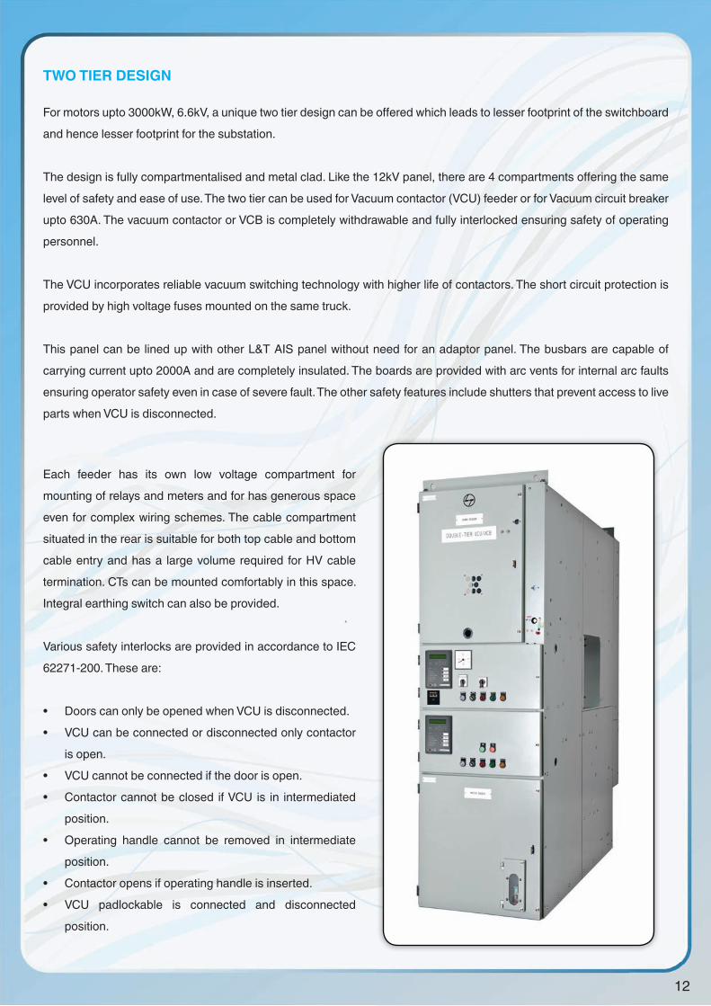
TWO TIER DESIGN
For motors upto 3000kW, 6.6kV, a unique two tier design can be off ered which leads to lesser footprint of the switchboard
and hence lesser footprint for the substation.
The design is fully compartmentalised and metal clad. Like the 12kV panel, there are 4 compartments off ering the same
level of safety and ease of use. The two tier can be used for Vacuum contactor (VCU) feeder or for Vacuum circuit breaker
upto 630A. The vacuum contactor or VCB is completely withdrawable and fully interlocked ensuring safety of operating
personnel.
The VCU incorporates reliable vacuum switching technology with higher life of contactors. The short circuit protection is
provided by high voltage fuses mounted on the same truck.
This panel can be lined up with other L&T AIS panel without need for an adaptor panel. The busbars are capable of
carrying current upto 2000A and are completely insulated. The boards are provided with arc vents for internal arc faults
ensuring operator safety even in case of severe fault. The other safety features include shutters that prevent access to live
parts when VCU is disconnected.

12
1313 13
1313
13
CROSS SECTIONAL DRAWING
Latched Non latchedVoltageImpulse withstand voltageOne minute power frequency withstand voltageFrequencyNormal current 200A 400AShort circuit breaking currentMaking current (100 operations) 2000A 4000ABreaking current (25 operations) 1600A 3200APeak current (10msec) 55kA 85kADegree of protection
Width (in mm) 700 700
Depth (in mm) 1872 1872
Height (in mm) 2300 2300
Opening time (in msec)
Closing time at no load (in msec)
Full load switching life (No. of operations)
Closing voltage 110V-220V DC 110V-220V AC/DC
Tripping voltage 110V-220V DC -
Auxiliary contacts 6 NO+ 6 NC 6 NO+ 6 NC
7.2kV60kVp20kV50 Hz
15-25
60-80
2,50,000
63kA (fused)
VCU
IP4X (Higher IP can be offered on request)
DATA SHEET
1414
1414
14
15
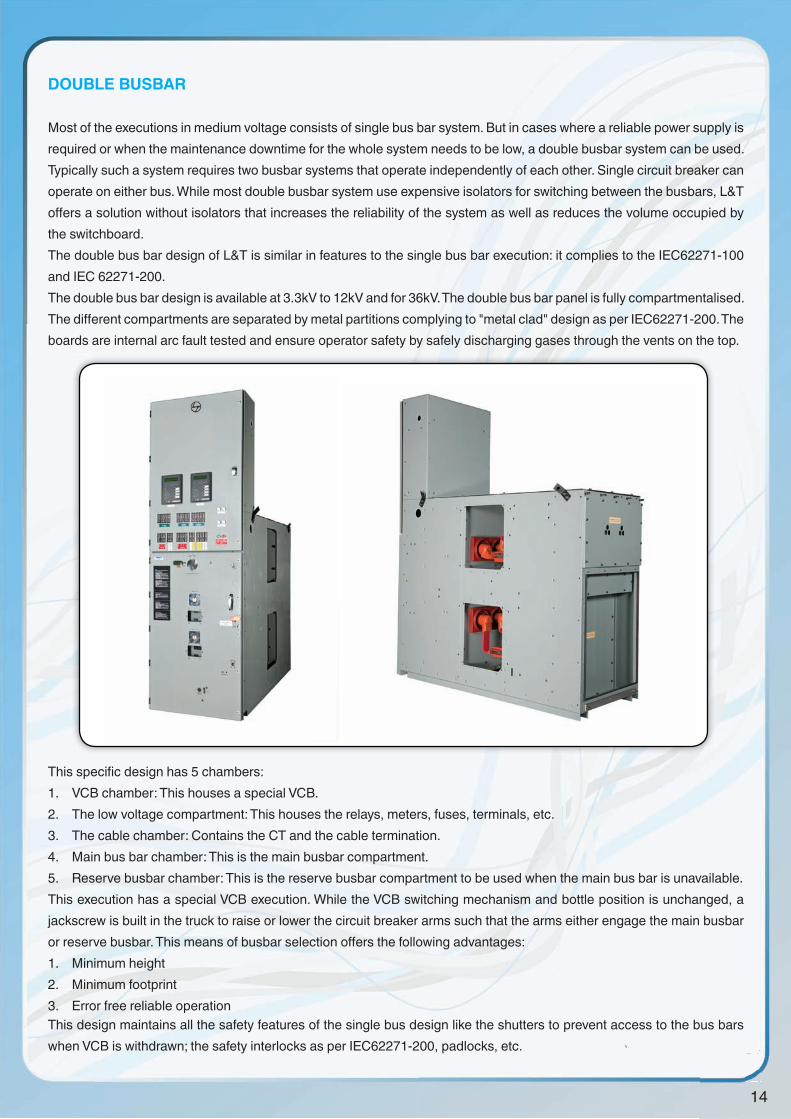
DOUBLE BUSBAR
Most of the executions in medium voltage consists of single bus bar system. But in cases where a reliable power supply is required or when the maintenance downtime for the whole system needs to be low, a double busbar system can be used.Typically such a system requires two busbar systems that operate independently of each other. Single circuit breaker can operate on either bus. While most double busbar system use expensive isolators for switching between the busbars, L&T off ers a solution without isolators that increases the reliability of the system as well as reduces the volume occupied by the switchboard.The double bus bar design of L&T is similar in features to the single bus bar execution: it complies to the IEC62271-100 and IEC 62271-200.The double bus bar design is available at 3.3kV to 12kV and for 36kV. The double bus bar panel is fully compartmentalised. The diff erent compartments are separated by metal partitions complying to "metal clad" design as per IEC62271-200. The boards are internal arc fault tested and ensure operator safety by safely discharging gases through the vents on the top.
This specifi c design has 5 chambers:1. VCB chamber: This houses a special VCB.2. The low voltage compartment: This houses the relays, meters, fuses, terminals, etc.3. The cable chamber: Contains the CT and the cable termination.4. Main bus bar chamber: This is the main busbar compartment.5. Reserve busbar chamber: This is the reserve busbar compartment to be used when the main bus bar is unavailable.This execution has a special VCB execution. While the VCB switching mechanism and bottle position is unchanged, a jackscrew is built in the truck to raise or lower the circuit breaker arms such that the arms either engage the main busbar or reserve busbar. This means of busbar selection off ers the following advantages:1. Minimum height2. Minimum footprint3. Error free reliable operationThis design maintains all the safety features of the single bus design like the shutters to prevent access to the bus bars when VCB is withdrawn; the safety interlocks as per IEC62271-200, padlocks, etc.

14
1515 15
1515
15
CROSS SECTIONAL DRAWING
Voltage 36kV
Impulse withstand voltage 170kVpOne minute power frequency withstand voltage
70kV
Transient recovery voltage 62kVp
Frequency
Normal current 1250A-2000A
Short circuit breaking current 20kA 25kA
Short circuit making current 50kA 63kA
Duration of short circuit 3 secs 3 secs
Degree of protection
Width (in mm) 1200
Depth (in mm) 3160
Height (in mm) 2400
Operating sequence
Opening time (in msec)
Break time
Full load switching life (No. of operations)
Closing voltage/Tripping voltage
Spring charging voltage
Auxiliary contacts
3 secs
Current rating
630A
6 NO+ 6 NC 6 NO + 6 NC
25
12kV
20
< 3 cycles
10,000
24V-220V DC
24V-220V DC / 110V-230V AC
1250A
2000A
12kV/36kV
12kV/36kV
IP4X (Higher IP can be offered on request)
1610/1870
2000
VCB
700/800 (depending on current and short circuit rating)
35
< 3 cycles
10,000
O-0.3 sec-CO-3 min-CO
25kA
63kA
12kV
75kVp
28kV
20.6kVp
630A – 2000A
50 Hz
Fault Level (kA)Normal Current (A)
DATA SHEET

1616
1616
16
Top Related