


Languages
Pages
Legal

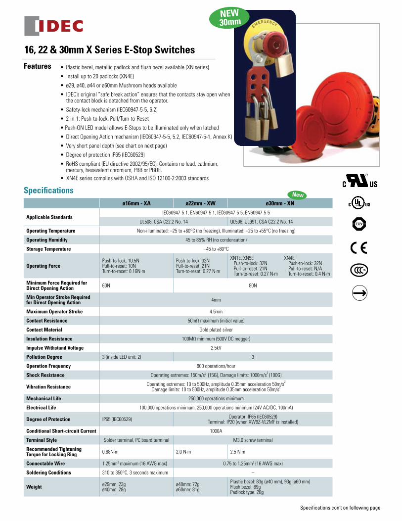
• Plasticbezel,metallicpadlockandflushbezelavailable(XNseries)
•Installupto20padlocks(XN4E)
• ø29,ø40,ø44orø60mmMushroomheadsavailable
• IDEC’soriginal“safebreakaction”ensuresthatthecontactsstayopenwhenthecontactblockisdetachedfromtheoperator.
• Safety-lockmechanism(IEC60947-5-5,6.2)
• 2-in-1:Push-to-lock,Pull/Turn-to-Reset
•Push-ONLEDmodelallowsE-Stopstobeilluminatedonlywhenlatched
• DirectOpeningActionmechanism(IEC60947-5-5,5.2,IEC60947-5-1,AnnexK)
• Veryshortpaneldepth(seechartonnextpage)
• DegreeofprotectionIP65(IEC60529)
• RoHScompliant(EUdirective2002/95/EC).Containsnolead,cadmium,mercury,hexavalentchromium,PBBorPBDE.
•XN4EseriescomplieswithOSHAandISO12100-2:2003standards
16, 22 & 30mm X Series E-Stop SwitchesFeatures
IDEC Corporation • 1175 Elko Drive Sunnyvale, CA 94089 • 800-262-IDEC (4332)
Fax: 408-745-5258 • www.IDEC.com/usa
©2010 IDEC Corporation. All Rights Reserved. Catalog No. XS9Y-DS100-1 01/10 10K
For more information on the these and other IDEC E-Stops, visit:
www.IDEC.com/usa/estop
www.IDEC.com 800-262-IDEC
Specifications con’t on following page
NEW 30mm
Specificationsø16mm - XA ø22mm - XW ø30mm - XN
Applicable StandardsIEC60947-5-1,EN60947-5-1,IEC60947-5-5,EN60947-5-5
UL508,CSAC22.2No.14 UL508,UL991,CSAC22.2No.14
Operating Temperature Non-illuminated:–25to+60°C(nofreezing),Illuminated:–25to+55°C(nofreezing)
Operating Humidity 45to85%RH(nocondensation)
Storage Temperature –45to+80°C
Operating ForcePush-to-lock:10.5NPull-to-reset:10NTurn-to-reset:0.16N·m
Push-to-lock:32NPull-to-reset:21NTurn-to-reset:0.27N·m
XN1E,XN5EXN4EPush-to-lock:32NPush-to-lock:32NPull-to-reset:21NPull-to-reset:N/ATurn-to-reset:0.27N·mTurn-to-reset:0.4N·m
Minimum Force Required for Direct Opening Action 60N 80N
Min Operator Stroke Required for Direct Opening Action 4mm
Maximum Operator Stroke 4.5mm
Contact Resistance 50mΩmaximum(initialvalue)
Contact Material Goldplatedsilver
Insulation Resistance 100MΩminimum(500VDCmegger)
Impulse Withstand Voltage 2.5kV
Pollution Degree 3(insideLEDunit:2) 3
Operation Frequency 900operations/hour
Shock Resistance Operatingextremes:150m/s2(15G),Damagelimits:1000m/s2(100G)
Vibration Resistance Operatingextremes:10to500Hz,amplitude0.35mmacceleration50m/s2Damagelimits:10to500Hz,amplitude0.35mmacceleration50m/s2
Mechanical Life 250,000operationsminimum
Electrical Life 100,000operationsminimum,250,000operationsminimum(24VAC/DC,100mA)
Degree of Protection IP65(IEC60529) Operator:IP65(IEC60529)Terminal:IP20(whenXW9Z-VL2MFisinstalled)
Conditional Short-circuit Current 1000A
Terminal Style Solderterminal,PCboardterminal M3.0screwterminal
Recommended Tightening Torque for Locking Ring 0.88N·m 2.0N·m 2.5N·m
Connectable Wire 1.25mm2maximum(16AWGmax) 0.75to1.25mm2(16AWGmax)
Soldering Conditions 310to350°C,3secondsmaximum –
Weight ø29mm:23gø40mm:28g
ø40mm:72gø60mm:81g
Plasticbezel:83g(ø40mm),93g(ø60mm)Flushbezel:89gPadlocktype:20g
New
3347.7
20.1
18.5
ø40
Panel Thickness1 to 5
37
Terminal CoverXW9Z-VL2M
Rubber GasketLocking Ring
M3 TerminalScrews
33.0
+0.
50
4.8+0.20
R0.8 max.ø30.5 +0.50
Panel Cut-out
ø40 mmMushroom
ø60 mmJumbo Mushroom
33
ø60
Push-ONIlluminated
3347.7
20.1
18.5
37
33.0
+0.
50
4.8+0.20
R0.8 max.ø30.5 +0.50
Panel Cut-out
Panel Thickness 1 to 5Terminal CoverXW9Z-VL2M
Rubber GasketLocking Ring
M3 TerminalScrews ø40
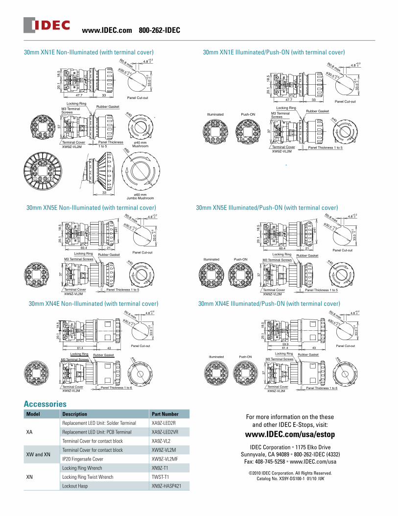
30mm XN1E Non-Illuminated (with terminal cover) 30mm XN1E Illuminated/Push-ON (with terminal cover)
ø41
2160.4
20.1
18.5
37
ø40
33.0
+0.
50
4.8+0.2 0
ø30.5
R0.8 max.+0.50
Panel Cut-out
Panel Thickness 1 to 5Terminal CoverXW9Z-VL2M
Rubber GasketLocking Ring
M3 Terminal Screws Push-ONIlluminated
ø41
2160.4
20.1
18.5
37
Rubber GasketLocking Ring
M3 Terminal Screws ø40
33.0
+0.
50
4.8+0.2 0
ø30.5
R0.8 max.+0.50
Panel Cut-out
Panel Thickness 1 to 5Terminal CoverXW9Z-VL2M
61.4
20.1
18.5
43
ø44
33.0
+0.
50
4.8+0.20
R0.8 max.ø30.5 +0.50
Panel Cut-out
Rubber GasketLocking Ring
M3 Terminal Screws
Panel Thickness 1 to 6Terminal CoverXW9Z-VL2M
61.459.9
20.1
18.5
43
37
ø44
33.0
+0.5 0
4.8+0.20
R0.8 max.ø30.5 +0.50
Panel Cut-out
Panel Thickness 1 to 6Terminal CoverXW9Z-VL2M
Rubber GasketLocking Ring
M3 Terminal ScrewsPush-ONIlluminated
30mm XN5E Non-Illuminated (with terminal cover) 30mm XN5E Illuminated/Push-ON (with terminal cover)
30mm XN4E Non-Illuminated (with terminal cover) 30mm XN4E Illuminated/Push-ON (with terminal cover)
AccessoriesModel Description Part Number
XA
ReplacementLEDUnit:SolderTerminal XA9Z-LED2R
ReplacementLEDUnit:PCBTerminal XA9Z-LED2VR
TerminalCoverforcontactblock XA9Z-VL2
XW and XNTerminalCoverforcontactblock XW9Z-VL2M
IP20FingersafeCover XW9Z-VL2MF
XN
LockingRingWrench XN9Z-T1
LockingRingTwistWrench TWST-T1
LockoutHasp XN9Z-HASP421

www.IDEC.com 800-262-IDEC www.IDEC.com 800-262-IDEC
Contact Ratings
Rated Insulation Voltage (Ui)XA 300V (illuminated part: 60V)
XW, XN 250V
Rated Current (Ith) XA, XW, XN 5A
Rated Operating Voltage (Ue) 30V 125V 250V
Rate
d O
pera
ting
Curr
ent
Mai
n
Cont
acts
(NC)
AC 50/60 Hz
Resistive Load (AC-12)XA – 3A 3A
XW, XN – 5A 3A
Inductive Load (AC-15)XA – 1.5A 1.5A
XW, XN 3A 1.5A
DCResistive Load (DC-12)
XA, XW, XN
2A 0.4A 0.2A
Inductive Load (DC-13) 1A 0.22A 0.1A
Mon
itor
Cont
acts
(NO
)
AC 50/60 HzResistive Load (AC-12) – 1.2A 0.6A
Inductive Load (AC-14) – 0.6A 0.3A
DCResistive Load (DC-12) 2A 0.4A 0.2A
Inductive Load (DC-13) 1A 0.22A 0.1A
• Minimum applicable load: 5V AC/DC, 1mA (reference value). • The rated operating currents are measured at resistive/inductive load types specified in IEC 60947-5-1.
Illuminated Unit LED RatingsModel Rated Voltage Operating Voltage Rated Current
16mm XA24V AC/DC 24V AC/DC ±10%
11mA
22mm XW 30mm XN 15mA
Depth Behind the PanelModel Depth
(mm) Description
16mmXA 27.9 1-4contacts,bothilluminated&non-illuminated
22mmXW 48.7 1-4contacts,bothilluminated&non-illuminated
30mmXN
47.7 1-4contacts,plasticbezel
60.4 1-4contacts,flushbezel
61.4 1-4contacts,padlock
Solder Terminal TypePC Board Terminal Type
3.1
Locking RingRubber Gasket
Mounting Panel Thickness: 0.5 to 3.7
XA9Z-VL2Terminal Cover
19.8
8.7
2.1
27.2
25.8 20.630.4
29.4
30.4
ø29.8
16mm XA Non-Illuminated
Dimensions (mm)16mm XA Illuminated
Solder Terminal Type
27.2
19.8
8.7
4.5
Mounting Panel Thickness: 0.5 to 3.7
2.1 25.8 20.630.4
PC Board Terminal Type
3.1
29.4
30.4
ø29.8
Locking RingRubber Gasket
XA9Z-VL2Terminal Cover
22mm XW LED Illuminated/Push-ON (with terminal cover)22mm XW Non-Illuminated (with terminal cover)
ø22.3
ø60
32
ø4018.5 20.1
Panel Cut-out
0+0.23.2
0+0.4
24.1
R0.8 max. 0+0.4
Panel Thickness 0.8 to 6
Gasket
Terminal CoverXW9Z-VL2M
M3 Terminal ScrewLocking Ring
32
0.5
48.7
37
47.2
R
ø22.3
ø60
32
ø4018.5 20.1
Panel Cut-out
0+0.23.2
0+0.4
24.1
R0.8 max. 0+0.4
Panel Thickness 0.8 to 6
Gasket
Terminal CoverXW9Z-VL2M
M3 Terminal ScrewLocking Ring
32
0.5
48.7
37
47.2
R
ø40mm Operator
ø60mm Operator
ø22.3
ø60
32
ø4018.5 20.1
Panel Cut-out
0+0.23.2
0+0.4
24.1
R0.8 max. 0+0.4
Panel Thickness 0.8 to 6
Gasket
Terminal CoverXW9Z-VL2M
M3 Terminal ScrewLocking Ring
32
0.5
48.7
37
47.2
R
Mounting Hole LayoutøA
X
Y
Part Numbers
XA1E - L V 3 11 Q4 V- RIlluminationB: Non-IlluminatedL: Illuminated
Mushroom Size3: ø29mm4: ø40mm
Contact Configuration*11: 1NO - 1NC02: 2NC 13: 1NO - 3NC04: 4NC
Terminalblank: solder tabV: PCB
Voltage Codeblank: Non-illuminatedQ4: Illuminated 24V AC/DC
PC Board Layout - Bottom View (for 16mm XA only)
3-ø1.7 holes
8.7
19.8
8.7
19.8
10-ø1.2 holes
6.5
11.2
Non-Illuminated
8.7
19.88.
719
.8
10-ø1.2 holes
6.5
11.2
4.5
3-ø1.7 holes
Illuminated
XW1E - L V 4 11 Q4M - RIlluminationB: Non-IlluminatedL: Illuminated LEDT: Illuminated Push-ON LED
Mushroom Size4: ø40mm5: ø60mm (non-illuminated only)
Contact Configuration*11: 1NO - 1NC02: 2NC 13: 1NO - 3NC04: 4NC22: 2NO-2NC12: 1NO-2NC (Push-ON LED only)
Voltage Code blank: Non-IlluminatedQ4: Illuminated 24V AC/DC
Terminal Arrangements (Bottom View)
Non-Illuminated
LED
TOP
X1 X2
L R
∗3 ∗4
∗1∗2
∗2∗1
Push-ON
Illuminated
• Contact Type
• Contact Number (1-4)
TOP
(Example: 1NO-3NC contact)
L R
11 12
34 33
2122
4241
1-2: NC main contact3-4: NO monitor contact
XA *: blankXW & XN Starting with the contact on TOP in a counterclockwise direction. Note: 1: contact on the TOP 2: contact on the Left 3: contact on the Bottom 4: contact on the Right
Terminal Marking Description
XN4E-LL411MR
16mm XA
ø29mm Operator
25.8
20.630.4ø40mm Operator
ø40
ø29
Panel Cut-out
0+0.2
ø16.2
0+0.2
1.7
0+0.2
17.9
TOPTOP
*1*2
*2*1
*1
*3*4
*2
TOP
*1*2
*4*3
*1
*3*4
*2*2
*1 *2
*2*1
*1
*1*2
L RL R
TOP
*1*2
*2*1
*1
*3*4
*2
L RL R
TOP
L R
∗3 ∗4
∗4 ∗3
∗1∗2
∗2∗1
TOPTOP
X2
*2
LED
*4 *3X1
*1
*1 *2
*2*1
TOP
X2
*2
LED
*4 *3X1
*1
*3 *4
*2*1*1
*2
*2*1
*1
X1
LED
*2
X2*1*2
L R
TOP
X2
*2
LED
*4 *3X1
*1
*3 *4
*2*1
L RL RL R
TOP
X2
LED
X1
L R
∗3 ∗4
∗4 ∗3
∗1∗2
∗2∗1
4NC 1NO-3NC 2NC 1NO-1NC 2NO-2NC 1NO-2NC
Panel Cut-out
0+0.2
3.2
0+0.4
24.1
0+0.4
ø22.3
R0.8 max.
ø40
48.7
Panel Thickness 0.8 to 6
Gasket
IP20 Protection CoverXW9Z-VL2MF
Locking Ring
M3 TerminalScrew
32
0.5
37
XW9Z-VL2M
M3 TerminalScrew
Panel Thickness 0.8 to 6
Gasket
Terminal Cover
Locking Ring
32
0.5
47.248.7
37
18.5 20.1
Push-ON
18.5 20.1
RR
Illuminated
Panel Cut-out
0+0.2
3.2
0+0.4
24.1
0+0.4
ø22.3
R0.8 max.
ø40
48.7
Panel Thickness 0.8 to 6
Gasket
IP20 Protection CoverXW9Z-VL2MF
Locking Ring
M3 TerminalScrew
32
0.5
37
XW9Z-VL2M
M3 TerminalScrew
Panel Thickness 0.8 to 6
Gasket
Terminal Cover
Locking Ring
32
0.5
47.248.7
37
18.5 20.1
LED Push-ON Type
18.5 20.1
RR
ø40mm Operator
Measurements
Size Model øA X & Y
16mmXAø29mm
16.2+0.240mmmin
ø40mm 50mmmin
22mmXW 22.3+0.4 70mmmin
30mmXN1E,XN5E 30.5+0.5 70mmmin
Note:ForXN4E,determinethevaluesaccordingtothesizeandnumberofpadlocksandhasp.
XN5E-BV411MR
XN1E - L V 4 02 Q4 MRBezel1: Plastic Bezel4: Padlock5: Flush Bezel
IlluminationXN1E, XN5E BV: Non-Illuminated LV: Illuminated LED TV: Illuminated Push-ON LEDXN4E BL: Non-Illuminated LL: Illuminated LED TL: Illuminated Push-ON LED
Mushroom Size4: ø40mm: XN1E, XN5E ø44mm: XN4E 5: ø60mm (XN1E non-illuminated only)
Contact Configuration*11: 1NO - 1NC02: 2NC 13: 1NO - 3NC22: 2NO - 2NC04: 4NC 12: 1NO-2NC (Push-ON LED only)
Voltage Code blank: Non-IlluminatedQ4: 24V AC/DC (Illuminated & Push-ON LED type)
*ContactIDECforadditionalcontactconfigurations.
New

www.IDEC.com 800-262-IDEC www.IDEC.com 800-262-IDEC
Contact Ratings
Rated Insulation Voltage (Ui)XA 300V (illuminated part: 60V)
XW, XN 250V
Rated Current (Ith) XA, XW, XN 5A
Rated Operating Voltage (Ue) 30V 125V 250V
Rate
d O
pera
ting
Curr
ent
Mai
n
Cont
acts
(NC)
AC 50/60 Hz
Resistive Load (AC-12)XA – 3A 3A
XW, XN – 5A 3A
Inductive Load (AC-15)XA – 1.5A 1.5A
XW, XN 3A 1.5A
DCResistive Load (DC-12)
XA, XW, XN
2A 0.4A 0.2A
Inductive Load (DC-13) 1A 0.22A 0.1A
Mon
itor
Cont
acts
(NO
)
AC 50/60 HzResistive Load (AC-12) – 1.2A 0.6A
Inductive Load (AC-14) – 0.6A 0.3A
DCResistive Load (DC-12) 2A 0.4A 0.2A
Inductive Load (DC-13) 1A 0.22A 0.1A
• Minimum applicable load: 5V AC/DC, 1mA (reference value). • The rated operating currents are measured at resistive/inductive load types specified in IEC 60947-5-1.
Illuminated Unit LED RatingsModel Rated Voltage Operating Voltage Rated Current
16mm XA24V AC/DC 24V AC/DC ±10%
11mA
22mm XW 30mm XN 15mA
Depth Behind the PanelModel Depth
(mm) Description
16mmXA 27.9 1-4contacts,bothilluminated&non-illuminated
22mmXW 48.7 1-4contacts,bothilluminated&non-illuminated
30mmXN
47.7 1-4contacts,plasticbezel
60.4 1-4contacts,flushbezel
61.4 1-4contacts,padlock
Solder Terminal TypePC Board Terminal Type
3.1
Locking RingRubber Gasket
Mounting Panel Thickness: 0.5 to 3.7
XA9Z-VL2Terminal Cover
19.8
8.7
2.1
27.2
25.8 20.630.4
29.4
30.4
ø29.8
16mm XA Non-Illuminated
Dimensions (mm)16mm XA Illuminated
Solder Terminal Type27
.219
.88.
74.
5
Mounting Panel Thickness: 0.5 to 3.7
2.1 25.8 20.630.4
PC Board Terminal Type
3.1
29.430
.4
ø29.8
Locking RingRubber Gasket
XA9Z-VL2Terminal Cover
22mm XW LED Illuminated/Push-ON (with terminal cover)22mm XW Non-Illuminated (with terminal cover)
ø22.3
ø60
32
ø4018.5 20.1
Panel Cut-out
0+0.23.2
0+0.4
24.1
R0.8 max. 0+0.4
Panel Thickness 0.8 to 6
Gasket
Terminal CoverXW9Z-VL2M
M3 Terminal ScrewLocking Ring
32
0.5
48.7
37
47.2
R
ø22.3
ø60
32
ø4018.5 20.1
Panel Cut-out
0+0.23.2
0+0.4
24.1
R0.8 max. 0+0.4
Panel Thickness 0.8 to 6
Gasket
Terminal CoverXW9Z-VL2M
M3 Terminal ScrewLocking Ring
32
0.5
48.7
37
47.2
R
ø40mm Operator
ø60mm Operator
ø22.3
ø60
32
ø4018.5 20.1
Panel Cut-out
0+0.23.2
0+0.4
24.1
R0.8 max. 0+0.4
Panel Thickness 0.8 to 6
Gasket
Terminal CoverXW9Z-VL2M
M3 Terminal ScrewLocking Ring
32
0.5
48.7
37
47.2
R
Mounting Hole LayoutøA
X
Y
Part Numbers
XA1E - L V 3 11 Q4 V- RIlluminationB: Non-IlluminatedL: Illuminated
Mushroom Size3: ø29mm4: ø40mm
Contact Configuration*11: 1NO - 1NC02: 2NC 13: 1NO - 3NC04: 4NC
Terminalblank: solder tabV: PCB
Voltage Codeblank: Non-illuminatedQ4: Illuminated 24V AC/DC
PC Board Layout - Bottom View (for 16mm XA only)
3-ø1.7 holes
8.7
19.8
8.7
19.8
10-ø1.2 holes
6.5
11.2
Non-Illuminated
8.7
19.8
8.7
19.8
10-ø1.2 holes
6.5
11.2
4.5
3-ø1.7 holes
Illuminated
XW1E - L V 4 11 Q4M - RIlluminationB: Non-IlluminatedL: Illuminated LEDT: Illuminated Push-ON LED
Mushroom Size4: ø40mm5: ø60mm (non-illuminated only)
Contact Configuration*11: 1NO - 1NC02: 2NC 13: 1NO - 3NC04: 4NC22: 2NO-2NC12: 1NO-2NC (Push-ON LED only)
Voltage Code blank: Non-IlluminatedQ4: Illuminated 24V AC/DC
Terminal Arrangements (Bottom View)
Non-Illuminated
LED
TOP
X1 X2
L R
∗3 ∗4
∗1∗2
∗2∗1
Push-ON
Illuminated
• Contact Type
• Contact Number (1-4)
TOP
(Example: 1NO-3NC contact)
L R
11 12
34 33
2122
4241
1-2: NC main contact3-4: NO monitor contact
XA *: blankXW & XN Starting with the contact on TOP in a counterclockwise direction. Note: 1: contact on the TOP 2: contact on the Left 3: contact on the Bottom 4: contact on the Right
Terminal Marking Description
XN4E-LL411MR
16mm XA
ø29mm Operator
25.8
20.630.4ø40mm Operator
ø40
ø29
Panel Cut-out
0+0.2
ø16.2
0+0.2
1.7
0+0.2
17.9
TOPTOP*1
*2*2*1
*1*3*4
*2
TOP
*1*2
*4*3
*1
*3*4
*2*2
*1 *2
*2*1
*1
*1*2
L RL R
TOP
*1*2
*2*1
*1
*3*4
*2
L RL R
TOP
L R
∗3 ∗4
∗4 ∗3
∗1∗2
∗2∗1
TOPTOP
X2
*2
LED
*4 *3X1
*1
*1 *2
*2*1
TOP
X2
*2LED
*4 *3X1
*1
*3 *4
*2*1*1
*2
*2*1
*1
X1
LED
*2
X2*1*2
L R
TOP
X2
*2
LED
*4 *3X1
*1
*3 *4
*2*1
L RL RL R
TOP
X2
LED
X1
L R
∗3 ∗4
∗4 ∗3
∗1∗2
∗2∗1
4NC 1NO-3NC 2NC 1NO-1NC 2NO-2NC 1NO-2NC
Panel Cut-out
0+0.2
3.2
0+0.4
24.1
0+0.4
ø22.3
R0.8 max.
ø40
48.7
Panel Thickness 0.8 to 6
Gasket
IP20 Protection CoverXW9Z-VL2MF
Locking Ring
M3 TerminalScrew
32
0.5
37
XW9Z-VL2M
M3 TerminalScrew
Panel Thickness 0.8 to 6
Gasket
Terminal Cover
Locking Ring
32
0.5
47.248.7
37
18.5 20.1
Push-ON
18.5 20.1
RR
Illuminated
Panel Cut-out
0+0.2
3.2
0+0.4
24.1
0+0.4
ø22.3
R0.8 max.
ø40
48.7
Panel Thickness 0.8 to 6
Gasket
IP20 Protection CoverXW9Z-VL2MF
Locking Ring
M3 TerminalScrew
32
0.5
37
XW9Z-VL2M
M3 TerminalScrew
Panel Thickness 0.8 to 6
Gasket
Terminal Cover
Locking Ring
32
0.5
47.248.7
37
18.5 20.1
LED Push-ON Type
18.5 20.1
RR
ø40mm Operator
Measurements
Size Model øA X & Y
16mmXAø29mm
16.2+0.240mmmin
ø40mm 50mmmin
22mmXW 22.3+0.4 70mmmin
30mmXN1E,XN5E 30.5+0.5 70mmmin
Note:ForXN4E,determinethevaluesaccordingtothesizeandnumberofpadlocksandhasp.
XN5E-BV411MR
XN1E - L V 4 02 Q4 MRBezel1: Plastic Bezel4: Padlock5: Flush Bezel
IlluminationXN1E, XN5E BV: Non-Illuminated LV: Illuminated LED TV: Illuminated Push-ON LEDXN4E BL: Non-Illuminated LL: Illuminated LED TL: Illuminated Push-ON LED
Mushroom Size4: ø40mm: XN1E, XN5E ø44mm: XN4E 5: ø60mm (XN1E non-illuminated only)
Contact Configuration*11: 1NO - 1NC02: 2NC 13: 1NO - 3NC22: 2NO - 2NC04: 4NC 12: 1NO-2NC (Push-ON LED only)
Voltage Code blank: Non-IlluminatedQ4: 24V AC/DC (Illuminated & Push-ON LED type)
*ContactIDECforadditionalcontactconfigurations.
New
• Plasticbezel,metallicpadlockandflushbezelavailable(XNseries)
•Installupto20padlocks(XN4E)
• ø29,ø40,ø44orø60mmMushroomheadsavailable
• IDEC’soriginal“safebreakaction”ensuresthatthecontactsstayopenwhenthecontactblockisdetachedfromtheoperator.
• Safety-lockmechanism(IEC60947-5-5,6.2)
• 2-in-1:Push-to-lock,Pull/Turn-to-Reset
•Push-ONLEDmodelallowsE-Stopstobeilluminatedonlywhenlatched
• DirectOpeningActionmechanism(IEC60947-5-5,5.2,IEC60947-5-1,AnnexK)
• Veryshortpaneldepth(seechartonnextpage)
• DegreeofprotectionIP65(IEC60529)
• RoHScompliant(EUdirective2002/95/EC).Containsnolead,cadmium,mercury,hexavalentchromium,PBBorPBDE.
•XN4EseriescomplieswithOSHAandISO12100-2:2003standards
16, 22 & 30mm X Series E-Stop SwitchesFeatures
IDEC Corporation • 1175 Elko Drive Sunnyvale, CA 94089 • 800-262-IDEC (4332)
Fax: 408-745-5258 • www.IDEC.com/usa
©2010 IDEC Corporation. All Rights Reserved. Catalog No. XS9Y-DS100-1 01/10 10K
For more information on the these and other IDEC E-Stops, visit:
www.IDEC.com/usa/estop
www.IDEC.com 800-262-IDEC
Specifications con’t on following page
NEW 30mm
Specificationsø16mm - XA ø22mm - XW ø30mm - XN
Applicable StandardsIEC60947-5-1,EN60947-5-1,IEC60947-5-5,EN60947-5-5
UL508,CSAC22.2No.14 UL508,UL991,CSAC22.2No.14
Operating Temperature Non-illuminated:–25to+60°C(nofreezing),Illuminated:–25to+55°C(nofreezing)
Operating Humidity 45to85%RH(nocondensation)
Storage Temperature –45to+80°C
Operating ForcePush-to-lock:10.5NPull-to-reset:10NTurn-to-reset:0.16N·m
Push-to-lock:32NPull-to-reset:21NTurn-to-reset:0.27N·m
XN1E,XN5EXN4EPush-to-lock:32NPush-to-lock:32NPull-to-reset:21NPull-to-reset:N/ATurn-to-reset:0.27N·mTurn-to-reset:0.4N·m
Minimum Force Required for Direct Opening Action 60N 80N
Min Operator Stroke Required for Direct Opening Action 4mm
Maximum Operator Stroke 4.5mm
Contact Resistance 50mΩmaximum(initialvalue)
Contact Material Goldplatedsilver
Insulation Resistance 100MΩminimum(500VDCmegger)
Impulse Withstand Voltage 2.5kV
Pollution Degree 3(insideLEDunit:2) 3
Operation Frequency 900operations/hour
Shock Resistance Operatingextremes:150m/s2(15G),Damagelimits:1000m/s2(100G)
Vibration Resistance Operatingextremes:10to500Hz,amplitude0.35mmacceleration50m/s2Damagelimits:10to500Hz,amplitude0.35mmacceleration50m/s2
Mechanical Life 250,000operationsminimum
Electrical Life 100,000operationsminimum,250,000operationsminimum(24VAC/DC,100mA)
Degree of Protection IP65(IEC60529) Operator:IP65(IEC60529)Terminal:IP20(whenXW9Z-VL2MFisinstalled)
Conditional Short-circuit Current 1000A
Terminal Style Solderterminal,PCboardterminal M3.0screwterminal
Recommended Tightening Torque for Locking Ring 0.88N·m 2.0N·m 2.5N·m
Connectable Wire 1.25mm2maximum(16AWGmax) 0.75to1.25mm2(16AWGmax)
Soldering Conditions 310to350°C,3secondsmaximum –
Weight ø29mm:23gø40mm:28g
ø40mm:72gø60mm:81g
Plasticbezel:83g(ø40mm),93g(ø60mm)Flushbezel:89gPadlocktype:20g
New
3347.7
20.1
18.5
ø40
Panel Thickness1 to 5
37
Terminal CoverXW9Z-VL2M
Rubber GasketLocking Ring
M3 TerminalScrews
33.0
+0.
50
4.8+0.20
R0.8 max.ø30.5 +0.50
Panel Cut-out
ø40 mmMushroom
ø60 mmJumbo Mushroom
33
ø60
Push-ONIlluminated
3347.7
20.1
18.5
37
33.0
+0.
50
4.8+0.20
R0.8 max.ø30.5 +0.50
Panel Cut-out
Panel Thickness 1 to 5Terminal CoverXW9Z-VL2M
Rubber GasketLocking Ring
M3 TerminalScrews ø40
30mm XN1E Non-Illuminated (with terminal cover) 30mm XN1E Illuminated/Push-ON (with terminal cover)
ø41
2160.4
20.1
18.5
37
ø40
33.0
+0.
50
4.8+0.2 0
ø30.5
R0.8 max.+0.50
Panel Cut-out
Panel Thickness 1 to 5Terminal CoverXW9Z-VL2M
Rubber GasketLocking Ring
M3 Terminal Screws Push-ONIlluminated
ø41
2160.4
20.1
18.5
37Rubber GasketLocking Ring
M3 Terminal Screws ø40
33.0
+0.
50
4.8+0.2 0
ø30.5
R0.8 max.+0.50
Panel Cut-out
Panel Thickness 1 to 5Terminal CoverXW9Z-VL2M
61.4
20.1
18.5
43
ø44
33.0
+0.
50
4.8+0.20
R0.8 max.ø30.5 +0.50
Panel Cut-out
Rubber GasketLocking Ring
M3 Terminal Screws
Panel Thickness 1 to 6Terminal CoverXW9Z-VL2M
61.459.9
20.1
18.5
43
37
ø44
33.0
+0.5 0
4.8+0.20
R0.8 max.ø30.5 +0.50
Panel Cut-out
Panel Thickness 1 to 6Terminal CoverXW9Z-VL2M
Rubber GasketLocking Ring
M3 Terminal ScrewsPush-ONIlluminated
30mm XN5E Non-Illuminated (with terminal cover) 30mm XN5E Illuminated/Push-ON (with terminal cover)
30mm XN4E Non-Illuminated (with terminal cover) 30mm XN4E Illuminated/Push-ON (with terminal cover)
AccessoriesModel Description Part Number
XA
ReplacementLEDUnit:SolderTerminal XA9Z-LED2R
ReplacementLEDUnit:PCBTerminal XA9Z-LED2VR
TerminalCoverforcontactblock XA9Z-VL2
XW and XNTerminalCoverforcontactblock XW9Z-VL2M
IP20FingersafeCover XW9Z-VL2MF
XN
LockingRingWrench XN9Z-T1
LockingRingTwistWrench TWST-T1
LockoutHasp XN9Z-HASP421
Top Related