


Languages
Pages
Legal


Page 1
Corp. 1014-L8
LCH SERIES
Service Literature
13 to 25 ton46 to 88 kWRevised 05/2020
LCH156H through 300S/U
The LCH156H, 180H, 180U, 210H, 240U, 300S, 300U 13
through 25 ton (46 through 88 kW) units, are configure to
order units (CTO) with a wide selection of factory
installed options.
Cooling capacities range from 13 to 25 tons (45.7 to 88 kW).
LCH156H, 180H, and 210H utilize three compressors while
LCH180U, 240H, 240U, 300S and 300U utilize four com
pressors.
Optional electric heat is factory- or field-installed. Electric
heat operates in single or multiple stages depending on the
kW input size. 15kW to 60 kW heat sections are available
for the LCH156H and 180H units and 15 kW to 90 kW heat
sections are available for the LCH210H, 240H, 300S,
300U.
Multi-Staged Air Volume MSAV blower option is available.
The VFD-driven blower will operate at lower speeds when
demand is low and increase to higher speeds when deman
d is high.
Variable speed VAV system is available as an option which
enables supply duct static measurement to control blower
CFM and discharge air temperature to control cooling
stages.
Units are designed to accept any of several different ener
gy management thermostat control systems with mini
mum field wiring. Factory- or field-provided control options
connect to the unit through Smartwire� connectors.
When ”plugged in” the controls become an integral part of
the unit wiring.
Information contained in this manual is intended for use by
qualified service technicians only. All specifications are sub
ject to change. Procedures outlined in this manual are pre
sented as a recommendation only and do not supersede or
replace local or state codes.
If the unit must be lifted for service, rig unit by attaching four
cables to the holes located in the unit base rail (two holes at
each corner). Refer to the installation instructions for the proper
rigging technique.
CAUTIONAs with any mechanical equipment, contact withsharp sheet metal edges can result in personal injury. Take care while handling this equipment andwear gloves and protective clothing.
WARNINGImproper installation, adjustment, alteration, serviceor maintenance can cause property damage, personal injury or loss of life. Installation and service mustbe performed by a qualified installer or serviceagency.
WARNINGElectric shock hazard. Can cause injuryor death. Before attempting to performany service or maintenance, turn theelectrical power to unit OFF at disconnect switch(es). Unit may have multiplepower supplies.
Table of Contents
Options / Accessories Page 2. . . . . . . . . . . . . . . . . . . . .
Specifications Page 9. . . . . . . . . . . . . . . . . . . . . . . . . . . .
Blower Data Page 14. . . . . . . . . . . . . . . . . . . . . . . . . . . . .
Electrical Data Page 17. . . . . . . . . . . . . . . . . . . . . . . . . . .
Electrical Heat Capacities Page 25. . . . . . . . . . . . . . . . .
Control Box Parts Arrangement Page 26. . . . . . . . . . . .
Unit Parts Arrangement Page 28. . . . . . . . . . . . . . . . . . .
I Unit Components Page 28. . . . . . . . . . . . . . . . . . . . . . .
II Placement and Installation Page 46. . . . . . . . . . . . . . .
III Charging Page 46. . . . . . . . . . . . . . . . . . . . . . . . . . . . . .
IV Start Up - Operation Page 79. . . . . . . . . . . . . . . . . . . .
V System Service Checks Page 82. . . . . . . . . . . . . . . .
VI Maintenance Page 82. . . . . . . . . . . . . . . . . . . . . . . . . .
VII Accessories Page 82. . . . . . . . . . . . . . . . . . . . . . . . .
VIII Wiring and Operation Sequence Page 97. . . . . . . .

Page 2
OPTIONS / ACCESSORIES
Item Description Model Number
Catalog Number
Unit Model No156 180 210 240 300
COOLING SYSTEMCondensate Drain Trap PVC - C1TRAP20AD2 76W26 OX OX OX OX OX
Copper - C1TRAP10AD2 76W27 OX OX OX OX OXConventional Fin/Tube Condenser Coil (replaces Environ™ Coil System) Factory O O O O OCorrosion Protection Factory O O O O ODrain Pan Overflow Switch E1SNSR71AD1 68W88 OX OX OX OX OXEfficiency High O O O O
Standard ORefrigerant Type R-410A O O O O OService valves (not for Environ™ Coil System or Humiditrol® Dehumidification) Factory O O O O O
BLOWER - SUPPLY AIRBlower Option CAV (Constant Air Volume) Factory O O O O O
VAV (Variable Air Volume) supply air blower option (Without VFD Bypass Control) Factory O O OMSAV® (Multi-Stage Air Volume) supply air blower option (With VFD Bypass Control) Factory O O O O O
MSAV® (Multi-Stage Air Volume) supply air blower option (Without VFD Bypass Control) Factory O O O O OMotors - CAV (Constant Air Volume) Belt Drive (standard efficiency) - 2 hp Factory O
Belt Drive (standard or high efficiency) - 3 hp Factory O O OBelt Drive (standard efficiency) - 5 hp Factory O O O O O
Belt Drive (standard efficiency) - 7.5 hp Factory O O O OBelt Drive (standard efficiency) - 10 hp Factory O O
Motors - VAV (Variable Air Volume) Belt Drive (standard or high efficiency) - 2 hp Factory OBelt Drive (standard or high efficiency) - 3 hp Factory O O
Belt Drive (standard efficiency) - 5 hp Factory O O OBelt Drive (standard efficiency) - 7.5 hp Factory O OBelt Drive (standard efficiency) - 10 hp Factory O
Motors - MSAV® (Multi-Stage Air Volume) Belt Drive (standard efficiency) - 2 hp Factory OBelt Drive (standard efficiency) - 3 hp Factory O O OBelt Drive (standard efficiency) - 5 hp Factory O O O O O
Belt Drive (standard efficiency) - 7.5 hp Factory O O O OBelt Drive (standard efficiency) - 10 hp Factory O O
Drive KitsSee Blower Data Tables for usage and selection
Kit #1 535-725 rpm Factory O O OKit #2 710-965 rpm Factory O O OKit #3 685-856 rpm Factory O O O O O
Kit #4 850-1045 rpm Factory O O O O OKit #5 945-1185 rpm Factory O O O O OKit #6 850-1045 rpm Factory O O O OKit #7 945-1185 rpm Factory O O O O
Kit #8 1045-1285 rpm Factory O O O OKit #10 1045-1285 rpm Factory O OKit #11 1135-1365 rpm Factory O O
Blower Belt Auto-Tensioner Factory O O O O O
CABINETCombination Coil/Hail Guards
Environ™ Coil System - C1GARD52C12 15T92 XEnviron™ Coil System - C1GARD52C22 15T93 X X X X
Conventional Fin/Tube Condenser Coil - C1GARD51C11 13T08 XConventional Fin/Tube Condenser Coil - C1GARD51C21 13T12 X X X X
NOTE - Catalog and model numbers shown are for ordering field installed accessories.OX = Configure To Order (Factory Installed) or Field InstalledO = Configure To Order (Factory Installed)X = Field Installed

Page 3
OPTIONS / ACCESSORIES
Item Description Model Number
Catalog Number
Unit Model No156 180 210 240 300
CONTROLSBlower Proving Switch C1SNSR35FF1 53W65 OX OX OX OX OXCommercial Controls
Prodigy® Control System - BACnet® Module - C0CTRL60AE1L 59W51 OX OX OX OX OXProdigy® Control System - LonTalk® Module - C0CTRL65FF1 54W27 OX OX OX OX OX
Novar® LSE Factory O O O O OL Connection® Building Automation System - - - X X X X X
Dirty Filter Switch E1SNSR55C-1 53W68 OX OX OX OX OXFresh Air Tempering C1SNSR75AD1 58W63 OX OX OX OX OXGeneral Purpose Control Kit E1GPBK30C1 13J78 X X X X XSmoke Detector - Supply or Return (Power board and one sensor) C1SNSR44C-1 83W40 OX OX OX OX OX
Smoke Detector - Supply and Return (Power board and two sensors) C1SNSR43C-1 83W41 OX OX OX OX OX
INDOOR AIR QUALITYAir FiltersHealthy Climate® High Efficiency Air Filters 24 x 24 x 2 (Order 6 per unit)
MERV 8 - C1FLTR15C-1- 54W67 OX OX OX OX OXMERV 13 - C1FLTR40C-1- 52W40 OX OX OX OX OX
Replacement Media Filter With Metal Mesh Frame (includes non-pleated filter media)
C1FLTR30C-1- 44N61 OX OX OX OX OX
Indoor Air Quality (CO2) SensorsSensor - Wall-mount, off-white plastic cover with LCD display C0SNSR50AE1L 77N39 X X X X XSensor - Wall-mount, off-white plastic cover, no display C0SNSR52AE1L 87N53 X X X X XSensor - Black plastic case with LCD display, rated for plenum mounting
C0SNSR51AE1L 87N52 X X X X X
Sensor - Wall-mount, black plastic case, no display, rated for plenum mounting
C0MISC19AE1 87N54 X X X X X
CO2 Sensor Duct Mounting Kit - for downflow applications C0MISC19AE1- 85L43 X X X X XAspiration Box - for duct mounting non-plenum rated CO2 sensors (87N53 or 77N39)
C0MISC16AE1- 90N43 X X X X X
UVC Germicidal Light Kit1 Healthy Climate® UVC Light Kit (110/230v-1ph) C1UVCL10C-1 54W65 X X X X X
ELECTRICALVoltage 60 hz 208/230V - 3 phase Factory O O O O O
460V - 3 phase Factory O O O O O575V - 3 phase Factory O O O O O
Disconnect Switch (see Electric Heat Tables for usage,
80 amp - C1DISC080C-1 54W85 OX OX OX OX OX150 amp - C1DISC150C-1 54W86 OX OX OX OX OX250 amp - C1DISC250C-1 54W87 OX OX OX OX OX
² Short-Circuit Current Rating (SCCR) of 100kA (includes Phase/Voltage Detection) Factory O O O O OGFI Service Outlets
15 amp non-powered, field-wired (208/230V, 460V, 575V) LTAGFIK10/15 74M70 OX OX OX OX OX15 amp factory-wired and powered (208/230V, 460V, 575V) Factory O O O O O
20 amp non-powered, field-wired (575V only) C1GFCI20FF1 67E01 OX OX OX OX OXWeatherproof Cover for GFI C1GFCI99FF1 10C89 X X X X XPhase/Voltage Detection (Optional for CAV options only, furnished with VAV or MSAV® option) Factory O O O O O1 Lamps operate on 110-230V single-phase power supply. Step-down transformer must be field supplied for field installation in 460V and 575V rooftop units (transformer
is furnished for factory installed light kits). Alternately, a separate 110V power supply may be used to directly power the UVC ballast(s)2 Disconnect Switch not available with higher SCCR option. Short-Circuit Current Rating option not available on field installed electric heat or 90kW electric heat
(208/240V) models.NOTE - Catalog and model numbers shown are for ordering field installed accessories.OX = Configure To Order (Factory Installed) or Field InstalledO = Configure To Order (Factory Installed)X = Field Installed

Page 4
OPTIONS / ACCESSORIES
Item Description Model Number
Catalog Number
Unit Model No156 180 210 240 300
ELECTRIC HEAT15 kW 208/230V-3ph - C1EH0150C-1Y 53W84 OX OX OX OX OX
460V-3ph - C1EH0150C-1G 53W86 OX OX OX OX OX575V-3ph - C1EH0150C-1J 53W87 OX OX OX OX OX
30 kW 208/230V-3ph - C1EH0300C11Y 53W88 OX460V-3ph - C1EH0300C11G 53W90 OX575V-3ph - C1EH0300C11J 53W91 OX
208/230V-3ph - C1EH0300C21Y 53W92 OX OX OX OX460V-3ph - C1EH0300C21G 53W94 OX OX OX OX575V-3ph - C1EH0300C21J 53W95 OX OX OX OX
45 kW 208/230V-3ph - C1EH0450C11Y 53W96 OX460V-3ph - C1EH0450C11G 53W98 OX575V-3ph - C1EH0450C11J 53W99 OX
208/230V-3ph - C1EH0450C21Y 54W00 OX OX OX OX460V-3ph - C1EH0450C21G 54W02 OX OX OX OX575V-3ph - C1EH0450C21J 54W03 OX OX OX OX
60 kW 208/230V-3ph - C1EH0600C11Y 54W04 OX460V-3ph - C1EH0600C11G 54W06 OX575V-3ph - C1EH0600C11J 54W07 OX
208/230V-3ph - C1EH0600C21Y 54W08 OX OX OX OX460V-3ph - C1EH0600C21G 54W10 OX OX OX OX575V-3ph - C1EH0600C21J 54W11 OX OX OX OX
90 kW 208/230V-3ph - C1EH0900C-1Y 54W12 OX OX OX460V-3ph - C1EH0900C-1G 54W14 OX OX OX575V-3ph - C1EH0900C-1J 54W15 OX OX OX
SCR (Silicon Controlled Rectifier) Electric Heat ControlNOTE - The SCR option is not available with 45 kW, 60 kW and 90kW electric heat (208/230V) models.
Factory O O O O O
Thermostat (required) Y9682 X X X X XDuct Sensor (required) Y9683 X X X X XECONOMIZERHigh Performance Economizer (Approved for California Title 24 Building Standards / AMCA Class 1A Certified)High Performance Economizer Downflow or Horizontal - Includes Outdoor Air Hood. Order Downflow or Horizontal Barometric Relief Dampers separately.
E1ECON17C-2 16Y98 OX OX OX OX OX
Economizer ControlsDifferential Enthalpy (Not for Title 24) Order 2 - C1SNSR64FF1 53W64 OX OX OX OX OXSensible Control Sensor is Furnished Factory O O O O OSingle Enthalpy (Not for Title 24) C1SNSR64FF1 53W64 OX OX OX OX OXGlobal Control Sensor Field Provided Factory O O O O OBuilding Pressure Control E1GPBK20C1 13J77 X X X X XOutdoor Air CFM Control E1GPBK10C1 13J76 X X X X XBarometric Relief Dampers With Exhaust HoodDownflow Barometric Relief Dampers C1DAMP50C 54W78 OX OX OX OX OXHorizontal Barometric Relief Dampers LAGEDH18/24 16K99 X X X X XOUTDOOR AIROutdoor Air Dampers With Outdoor Air HoodMotorized C1DAMP20C-1 13U04 OX OX OX OX OXManual C1DAMP10C-2 13U05 OX OX OX OX OXNOTE - Catalog and model numbers shown are for ordering field installed accessories.OX = Configure To Order (Factory Installed) or Field InstalledO = Configure To Order (Factory Installed)X = Field Installed

Page 5
OPTIONS / ACCESSORIES
Item Description Model Number
Catalog Number
Unit Model No156 180 210 240 300
POWER EXHAUST
Standard Static 208/230V - C1PWRE11C-1Y 75W90 OX OX OX OX OX460V - C1PWRE11C-1G 75W91 OX OX OX OX OX575V - C1PWRE11C-1J 75W92 OX OX OX OX OX
SCCR, Standard Static 208/230V - C1PWRE11C-1Y 75W90 OX OX OX OX OX460V - C1PWRE11C-2G 17J93 OX OX OX OX OX575V - C1PWRE11C-2J 17J98 OX OX OX OX OX
HUMIDITROL® CONDENSER REHEAT OPTION (CAV AND MSAV®) MODELS ONLY
Humiditrol® Dehumification Option Factory O O O O OHumidity Sensor Kit, Remote mounted (required) C0SNSR31AE-1 17M50 X X X X X
ROOF CURBS
Hybrid Roof Curbs, Downflow8 in. height C1CURB70C-1 11F58 X X X X X14 in. height C1CURB71C-1 11F59 X X X X X18 in. height C1CURB72C-1 11F60 X X X X X24 in. height C1CURB73C-1 11F61 X X X X XAdjustable Pitch Curb14 in. height L1CURB55C 43W26 X X X X XStandard Roof Curbs, Horizontal - Requires Horizontal Return Air Panel Kit26 in. height - slab applications C1CURB14C-1 11T89 X X X X30 in. height - slab applications C1CURB15C-1 11T90 X37 in. height - rooftop applications C1CURB16C-1 11T96 X X X X41 in. height - rooftop applications C1CURB17C-1 11T97 XInsulation Kit For Standard Horizontal Roof Curbsfor C1CURB14C-1 (26 in.) C1INSU11C-1- 73K32 X X X Xfor C1CURB15C-1 (30 in.) C1INSU12C-1- 73K33 Xfor C1CURB16C-1 (37 in.) C1INSU13C-1- 73K34 X X X Xfor C1CURB17C-1 (41 in.) C1INSU14C-1- 73K35 XHorizontal Return Air Panel KitRequired for Horizontal Applications with Roof Curb C1HRAP10C-1- 87M00 X X X X X
CEILING DIFFUSERS
Step-Down - Order one RTD11-185S 13K63 X XRTD11-275S 13K64 X X X
Flush - Order one FD11-185S 13K58 X XFD11-275S 13K59 X X X
Transitions (Supply and Return) - Order one C1DIFF33C-1 12X68 X XC1DIFF34C-1 12X70 X X X
1 Order one 6 kW transformer per array (up to 24 solar modules each). Up to two arrays can be used per rooftop unit (total 48 modules). Arrays are field wired in parallel to the Solar Power Entry
NOTE - Catalog and model numbers shown are for ordering field installed accessories.OX = Configure To Order (Factory Installed) or Field InstalledO = Configure To Order (Factory Installed)X = Field Installed

Page 6
OPTIONS / ACCESSORIES
Item Description Model Number
Catalog Number
Unit Model No.180U 240U 300U
COOLING SYSTEM
Condensate Drain Trap PVC - C1TRAP20AD2 76W26 OX OX OX
Copper - C1TRAP10AD2 76W27 OX OX OX
Corrosion Protection Factory O O O
Drain Pan Overflow Switch E1SNSR71AD1 68W88 OX OX OX
Refrigerant Type R-410A O O O
BLOWER - SUPPLY AIR
Blower MSAV (multi-stage air volume) blower option (With VFD Bypass Control) Factory O O O
MSAV (multi-stage air volume) blower option (Without VFD Bypass Control) Factory O O O
Motors - MSAV (multi-stage air volume)
Belt Drive (standard efficiency) - 3 hp Factory O
Belt Drive (standard efficiency) - 5 hp Factory O O O
Belt Drive (standard efficiency) - 7.5 hp Factory O O O
Belt Drive (standard efficiency) - 10 hp Factory O O
Drive KitsSee Blower Data Tables for usage and selection
Kit #1 535-725 rpm Factory O
Kit #2 710-965 rpm Factory O
Kit #3 685-856 rpm Factory O O O
Kit #4 850-1045 rpm Factory O O O
Kit #5 945-1185 rpm Factory O O O
Kit #6 850-1045 rpm Factory O O O
Kit #7 945-1185 rpm Factory O O O
Kit #8 1045-1285 rpm Factory O O O
Kit #10 1045-1285 rpm Factory O O
Kit #11 1135-1365 rpm Factory O O
Blower Belt Auto-Tensioner Factory O O O
CABINET
Combination Coil/Hail Guards C1GARD51C21 13T12 X X X
CONTROLS
Blower Proving Switch C1SNSR35FF1 53W65 OX OX OX
Commercial Controls
Prodigy® Control System - BACnet® Module - C0CTRL60AE1L 59W51 OX OX OX
Prodigy® Control System - LonTalk® Module - C0CTRL65FF1 54W27 OX OX OX
Novar® ETM-2051 - E0CTRL30C1 64W74 OX OX OX
Novar® LSE Factory O O O
L Connection® Building Automation System - - - X X X
Dirty Filter Switch E1SNSR55C-1 53W68 OX OX OX
Fresh Air Tempering C1SNSR75AD1 58W63 OX OX OX
General Purpose Control Kit E1GPBK30C1 13J78 X X X
Smoke Detector - Supply or Return (Power board and one sensor) C1SNSR44C-1 83W40 OX OX OX
Smoke Detector - Supply and Return (Power board and two sensors) C1SNSR43C-1 83W41 OX OX OXNOTE - Catalog and model numbers shown are for ordering field installed accessories.OX = Configure To Order (Factory Installed) or Field InstalledO = Configure To Order (Factory Installed)X = Field Installed

Page 7
OPTIONS / ACCESSORIES
Item Description Model Number
Catalog Number
Unit Model No.180U 240U 300U
INDOOR AIR QUALITYAir FiltersHealthy Climate® High Efficiency Air Filters 24 x 24 x 2 (Order 6 per unit)
MERV 8 - C1FLTR15C-1- 54W67 OX OX OXMERV 13 - C1FLTR40C-1- 52W40 OX OX OX
Replacement Media Filter With Metal Mesh Frame (includes non-pleated filter media)
C1FLTR30C-1- 44N61 OX OX OX
Indoor Air Quality (CO2) SensorsSensor - Wall-mount, off-white plastic cover with LCD display C0SNSR50AE1L 77N39 X X XSensor - Wall-mount, off-white plastic cover, no display C0SNSR52AE1L 87N53 X X XSensor - Black plastic case with LCD display, rated for plenum mounting C0SNSR51AE1L 87N52 X X XSensor - Wall-mount, black plastic case, no display, rated for plenum mounting
C0MISC19AE1 87N54 X X X
CO2 Sensor Duct Mounting Kit - for downflow applications C0MISC19AE1- 85L43 X X XAspiration Box - for duct mounting non-plenum rated CO2 sensors (87N53 or 77N39)
C0MISC16AE1- 90N43 X X X
UVC Germicidal Light Kit1 Healthy Climate® UVC Light Kit (110/230v-1ph) C1UVCL10C-1 54W65 OX OX OXELECTRICALVoltage 60 hz 208/230V - 3 phase Factory O O O
460V - 3 phase Factory O O O575V - 3 phase Factory O O O
Disconnect Switch (see Electric Heat Tables for usage, page 27)
80 amp - C1DISC080C-1 54W85 OX OX OX150 amp - C1DISC150C-1 54W86 OX OX OX250 amp - C1DISC250C-1 54W87 OX OX OX
2 Short-Circuit Current Rating (SCCR) of 100kA (includes Phase/Voltage Detection) Factory O O OGFI Service Outlets
15 amp non-powered, field-wired (208/230V, 460V, 575V) LTAGFIK10/15 74M70 OX OX OX15 amp factory-wired and powered (208/230V, 460V, 575V) Factory O O O
20 amp non-powered, field-wired (575V only) C1GFCI20FF1 67E01 OX OX OXWeatherproof Cover for GFI C1GFCI99FF1 10C89 X X XELECTRIC HEAT15 kW 208/230V-3ph - C1EH0150C-1Y 53W84 OX OX OX
460V-3ph - C1EH0150C-1G 53W86 OX OX OX575V-3ph - C1EH0150C-1J 53W87 OX OX OX
30 kW 208/230V-3ph - C1EH0300C21Y 53W92 OX OX OX460V-3ph - C1EH0300C21G 53W94 OX OX OX575V-3ph - C1EH0300C21J 53W95 OX OX OX
45 kW 208/230V-3ph - C1EH0450C21Y 54W00 OX OX OX460V-3ph - C1EH0450C21G 54W02 OX OX OX575V-3ph - C1EH0450C21J 54W03 OX OX OX
60 kW 208/230V-3ph - C1EH0600C21Y 54W08 OX OX OX460V-3ph - C1EH0600C21G 54W10 OX OX OX575V-3ph - C1EH0600C21J 54W11 OX OX OX
90 kW 208/230V-3ph - C1EH0900C-1Y 54W12 OX OX460V-3ph - C1EH0900C-1G 54W14 OX OX575V-3ph - C1EH0900C-1J 54W15 OX OX
SCR (Silicon Controlled Rectifier) Electric Heat ControlNOTE - The SCR option is not available with 45 kW, 60 kW and 90kW electric heat (208/230V) models.
Factory O O O
Thermostat (required) Y9682 X X XDuct Sensor (required) Y9683 X X X1 Lamps operate on 110-230V single-phase power supply. Step-down transformer must be field supplied for field installation in 460V and 575V rooftop units (transformer
is furnished for factory installed light kits). Alternately, a separate 110V power supply may be used to directly power the UVC ballast(s)2 Disconnect Switch not available with higher SCCR option. Short-Circuit Current Rating option not available on field installed electric heat or 90kW electric heat
(208/240V) models.NOTE - Catalog and model numbers shown are for ordering field installed accessories.OX = Configure To Order (Factory Installed) or Field InstalledO = Configure To Order (Factory Installed)X = Field Installed

Page 8
OPTIONS / ACCESSORIES
Item Description Model Number
Catalog Number
Unit Model No.180U 240U 300U
ECONOMIZERHigh Performance Economizer (Approved for California Title 24 Building Standards / AMCA Class 1A Certified)High Performance Economizer Downflow or Horizontal - Includes Outdoor Air Hood. Order Downflow or Horizontal Barometric Relief Dampers separately.
E1ECON17C-2 16Y98 OX OX OX
Economizer ControlsDifferential Enthalpy (Not for Title 24) Order 2 - C1SNSR64FF1 53W64 OX OX OXSensible Control Sensor is Furnished Factory O O OSingle Enthalpy (Not for Title 24) C1SNSR64FF1 53W64 OX OX OXGlobal Control Sensor Field Provided Factory O O OBuilding Pressure Control E1GPBK10C1 13J77 X X XOutdoor Air CFM Control E1GPBK20C1 13J76 X X XBarometric Relief Dampers With Exhaust HoodDownflow Barometric Relief Dampers C1DAMP50C 54W78 OX OX OXHorizontal Barometric Relief Dampers LAGEDH18/24 16K99 X X XOUTDOOR AIROutdoor Air Dampers With Outdoor Air HoodMotorized C1DAMP20C-1 13U04 OX OX OXManual C1DAMP10C-2 13U05 OX OX OXPOWER EXHAUSTStandard Static 208/230V - C1PWRE11C-1Y 75W90 OX OX OX
460V - C1PWRE11C-1G 75W91 OX OX OX575V - C1PWRE11C-1J 75W92 OX OX OX
ROOF CURBSHybrid Roof Curbs, Downflow8 in. height C1CURB70C-1 11F58 X X X14 in. height C1CURB71C-1 11F59 X X X18 in. height C1CURB72C-1 11F60 X X X24 in. height C1CURB73C-1 11F61 X X XAdjustable Pitch Curb14 in. height L1CURB55C 43W26 X X XStandard Roof Curbs, Horizontal - Requires Horizontal Return Air Panel Kit26 in. height - slab applications C1CURB14C-1 11T89 X X X37 in. height - rooftop applications C1CURB16C-1 11T96 X X XInsulation Kit For Standard Horizontal Roof Curbsfor C1CURB14C-1 C1INSU11C-1- 73K32 X X Xfor C1CURB16C-1 C1INSU13C-1- 73K34 X X XHorizontal Return Air Panel KitRequired for Horizontal Applications with Roof Curb C1HRAP10C-1- 87M00 X X XCEILING DIFFUSERSStep-Down - Order one RTD11-185S 13K63 X
RTD11-275S 13K64 X XFlush - Order one FD11-185S 13K58 X
FD11-275S 13K59 X XTransitions (Supply and Return) - Order one C1DIFF33C-1 12X68 X
C1DIFF34C-1 12X70 X XNOTE - Catalog and model numbers shown are for ordering field installed accessories.OX = Configure To Order (Factory Installed) or Field InstalledO = Configure To Order (Factory Installed)X = Field Installed

Page 9
SPECIFICATIONSGeneral Data Nominal Tonnage 13 Ton 13 Ton 13 Ton
Model Number LCH156H4B LCH156H4V LCH156H4MEfficiency Type High High High
Blower Type CAV (Constant Air Volume)
VAV (Variable Air Volume)
MSAV® (Multi-Stage Air Volume)
Cooling Performance
Gross Cooling Capacity - Btuh 154,000 152,000 154,0001 Net Cooling Capacity - Btuh 150,000 148,000 150,000
AHRI Rated Air Flow - cfm 5000 4600 5000Total Unit Power - kW 12.5 12.3 12.5
1 EER (Btuh/Watt) 12.0 12.0 12.02 IEER (Btuh/Watt) 13.2 14.5 14.1
Refrigerant Charge
Refrigerant Type R-410A R-410A R-410AEnviron™ Coil System Circuit 1 5 lbs. 12 oz. 5 lbs. 0 oz. 5 lbs. 12 oz.
Circuit 2 5 lbs. 4 oz. 5 lbs. 8 oz. 5 lbs. 4 oz.Circuit 3 5 lbs. 10 oz. 5 lbs. 0 oz. 5 lbs. 10 oz.
Environ™ Coil System with Humiditrol®
Circuit 1 5 lbs. 14 oz. - - - 5 lbs. 14 oz.Circuit 2 5 lbs. 8 oz. - - - 5 lbs. 8 oz.Circuit 3 5 lbs. 12 oz. - - - 5 lbs. 12 oz.
Conventional Fin/Tube Coil Option
Circuit 1 10 lbs. 0 oz. - - - 10 lbs. 0 oz.Circuit 2 10 lbs. 0 oz. - - - 10 lbs. 0 oz.Circuit 3 9 lbs. 8 oz. - - - 9 lbs. 8 oz.
Conventional Fin/Tube With Humiditrol®
Circuit 1 12 lbs. 0 oz. - - - 12 lbs. 0 oz.Circuit 2 12 lbs. 0 oz. - - - 12 lbs. 0 oz.Circuit 3 9 lbs. 8 oz. - - - 9 lbs. 8 oz.
Electric Heat (kW) Available 15-30-45-60Compressor Type (number) Scroll (3) Scroll (3) Scroll (3)Outdoor Coils Environ™ (Fin/Tube)
Net face area (total) - sq. ft. 41.4 41.4 41.4Number of rows 1 (2) 1 (2) 1 (2)
Fins per inch 23 (20) 23 (20) 23 (20)Outdoor Coil Fans
Motor - (No.) horsepower (3) 1/3 (3) 1/3 (3) 1/3Motor rpm 1075 1075 1075
Total Motor watts 1100 1100 1100Diameter - (No.) in. (3) 24 (3) 24 (3) 24
Number of blades 3 3 3Total Air volume - cfm 12,000 12,000 12,000
Indoor Coils Net face area (total) - sq. ft. 21.4 21.4 21.4Tube diameter - in. 3/8 3/8 3/8
Number of rows 3 3 3Fins per inch 14 14 14
Drain connection - No. and size (1) 1 in. FPT (1) 1 in. FPT (1) 1 in. FPTExpansion device type Balance port TXV, removable head
3 Indoor Blower and Drive Selection
Nominal motor output 2 hp, 3 hp, 5 hpMax. usable motor output (US) 2.3 hp, 3.45 hp, 5.75 hp
Motor - Drive kit number 2 hp Kit 1 535-725 rpm Kit 2 710-965 rpm
3 hp Std. Eff. Kit 1 535-725 rpm Kit 2 710-965 rpm
3 hp High. Eff. Kit 3 685-856 rpm
Kit 4 850-1045 rpm 5 hp
Kit 3 - 685-856 rpm Kit 4 850-1045 rpm Kit 5 945-1185 rpm
Blower wheel nominal D x W - in. (2) 15 x 15 in. (2) 15 x 15 in. (2) 15 x 15 in.Filters Type of filter Fiberglass, disposable
Number and size - in. (6) 24 x 24 x 2Electrical characteristics 208/230V, 460V or 575V - 60 hertz - 3 phaseNOTE - Net capacity includes evaporator blower motor heat deduction. Gross capacity does not include evaporator blower motor heat deduction.1 AHRI Certified to AHRI Standard 340/360; 95°F outdoor air temperature and 80°F db/67°F wb entering evaporator air; minimum external duct static pressure.2 Integrated Energy Efficiency Ratio tested according to AHRI Standard 340/360.3 Using total air volume and system static pressure requirements determine from blower performance tables rpm and motor output required. Maximum usable output of
motors furnished are shown. In Canada, nominal motor output is also maximum usable motor output. If motors of comparable output are used, be sure to keep within the service factor limitations outlined on the motor nameplate.
NOTE – Units equipped with MSAV® (Multi-Stage Air Volume) option are limited to a motor service factor of 1.0.

Page 10
SPECIFICATIONSGeneral Data Nominal Tonnage 15 Ton 15 Ton 15 Ton 17.5 Ton 17.5 Ton
Model Number LCH180H4B LCH180H4V LCH180H4M LCH210H4B LCH210H4MEfficiency Type High High High High High
Blower Type CAV (Constant Air
Volume)
VAV (Variable Air
Volume)
MSAV® (Multi-Stage Air
Volume)
CAV (Constant Air
Volume)
MSAV® (Multi-Stage Air
Volume)Cooling Performance
Gross Cooling Capacity - Btuh 176,000 176,000 176,000 204,000 204,0001 Net Cooling Capacity - Btuh 172,000 172,000 172,000 198,000 198,000
AHRI Rated Air Flow - cfm 5250 5250 5250 6125 6125Total Unit Power - kW 14.3 14.3 14.3 16.5 16.5
1 EER (Btuh/Watt) 12.0 12.0 12.0 12.0 12.02 IEER (Btuh/Watt) 13.5 15.2 13.7 13.0 14.0
AHRI Reference No. 202088996 203353983 202088998 202088995 202088993Refrigerant Charge
Refrigerant Type R-410A R-410A R-410A R-410A R-410AEnviron™ Coil System Circuit 1 6 lbs. 0 oz. 5 lbs. 4 oz. 6 lbs. 0 oz. 6 lbs. 12 oz. 6 lbs. 12 oz.
Circuit 2 5 lbs. 10 oz. 5 lbs. 8 oz. 5 lbs. 10 oz. 6 lbs. 14 oz. 6 lbs. 14 oz.Circuit 3 5 lbs. 14 oz. 5 lbs. 8 oz. 5 lbs. 14 oz. 6 lbs. 14 oz. 6 lbs. 14 oz.
Environ™ Coil System with Humiditrol®
Circuit 1 6 lbs. 8 oz. - - - 6 lbs. 8 oz. 7 lbs. 4 oz. 7 lbs. 4 oz.Circuit 2 5 lbs. 12 oz. - - - 5 lbs. 12 oz. 7 lbs. 0 oz. 7 lbs. 0 oz.Circuit 3 6 lbs. 9 oz. - - - 6 lbs. 9 oz. 6 lbs. 4 oz. 6 lbs. 4 oz.
Conventional Fin/Tube Coil Option
Circuit 1 12 lbs. 8 oz. - - - 12 lbs. 8 oz. 13 lbs. 0 oz. 13 lbs. 0 oz.Circuit 2 12 lbs. 8 oz. - - - 12 lbs. 8 oz. 13 lbs. 0 oz. 13 lbs. 0 oz.Circuit 3 12 lbs. 8 oz. - - - 12 lbs. 8 oz. 13 lbs. 0 oz. 13 lbs. 0 oz.
Conventional Fin/Tube With Humiditrol®
Circuit 1 14 lbs. 8 oz. - - - 14 lbs. 8 oz. 15 lbs. 0 oz. 15 lbs. 0 oz.Circuit 2 14 lbs. 8 oz. - - - 14 lbs. 8 oz. 15 lbs. 0 oz. 15 lbs. 0 oz.Circuit 3 12 lbs. 8 oz. - - - 12 lbs. 8 oz. 13 lbs. 0 oz. 13 lbs. 0 oz.
Electric Heat (kW) Available 15-30-45-60 kW 15-30-45-60-90 kWCompressor Type (number) Scroll (3) Scroll (3) Scroll (3) Scroll (3) Scroll (3)Outdoor Coils Environ™ (Fin/Tube)
Net face area (total) - sq. ft. 55.2 55.2 55.2 55.2 55.2Number of rows 1 (2) 1 (2) 1 (2) 1 (2) 1 (2)
Fins per inch 23 (20) 23 (20) 23 (20) 23 (20) 23 (20)Outdoor Coil Fans
Motor - (No.) horsepower (4) 1/3 (4) 1/3 (4) 1/3 (6) 1/3 (6) 1/3Motor rpm 1075 1075 1075 1075 1075
Total Motor watts 1500 1500 1500 1950 1950Diameter - (No.) in. (4) 24 (4) 24 (4) 24 (6) 24 (6) 24
Number of blades 3 3 3 3 3Total Air volume - cfm 16,000 16,000 16,000 20,000 20,000
Indoor Coils Net face area (total) - sq. ft. 21.4 21.4 21.4 21.4 21.4Tube diameter - in. 3/8 3/8 3/8 3/8 3/8
Number of rows 3 3 3 4 4Fins per inch 14 14 14 14 14
Drain connection - No. and size (1) 1 in. FPT (1) 1 in. FPT (1) 1 in. FPT (1) 1 in. FPT (1) 1 in. FPTExpansion device type Balance port TXV, removable head
3 Indoor Blower and Drive Selection
Nominal motor output 3 hp, 5 hp, 7.5 hpMax. usable motor output (US) 3.45 hp, 5.75 hp, 8.62 hp
Motor - Drive kit number 3 hp Std. Eff. Kit 1 535-725 rpm Kit 2 710-965 rpm
3 hp High. Eff. Kit 3 - 685-856 rpm Kit 4 850-1045 rpm
5 hp Kit 3 685-856 rpm Kit 4 850-1045 rpm Kit 5 945-1185 rpm
7.5 hp Kit 6 850-1045 rpm Kit 7 945-1185 rpm
Kit 8 1045-1285 rpmBlower wheel nominal D x W - in. (2) 15 x 15
Filters Type of filter Fiberglass, disposableNumber and size - in. (6) 24 x 24 x 2
Electrical characteristics 208/230V, 460V or 575V - 60 hertz - 3 phaseNOTE - Net capacity includes evaporator blower motor heat deduction. Gross capacity does not include evaporator blower motor heat deduction.1 AHRI Certified to AHRI Standard 340/360; 95°F outdoor air temperature and 80°F db/67°F wb entering evaporator air; minimum external duct static pressure.2 Integrated Energy Efficiency Ratio tested according to AHRI Standard 340/360.3 Using total air volume and system static pressure requirements determine from blower performance tables rpm and motor output required. Maximum usable output of
motors furnished are shown. In Canada, nominal motor output is also maximum usable motor output. If motors of comparable output are used, be sure to keep within the service factor limitations outlined on the motor nameplate.
NOTE – Units equipped with MSAV® (Multi-Stage Air Volume) option are limited to a motor service factor of 1.0.

Page 11
SPECIFICATIONSGeneral Data Nominal Tonnage 20 Ton 20 Ton 20 Ton
Model Number LCH240H4B LCH240H4V LCH240H4MEfficiency Type High High High
Blower Type CAV (Constant Air Volume)
VAV (Variable Air Volume)
MSAV® (Multi-Stage Air Volume)
Cooling Performance
Gross Cooling Capacity - Btuh 238,000 238,000 238,0001 Net Cooling Capacity - Btuh 230,000 230,000 230,000
AHRI Rated Air Flow - cfm 6400 6400 6400Total Unit Power - kW 19.2 19.2 19.2
1 EER (Btuh/Watt) 12.0 12.0 12.02 IEER (Btuh/Watt) 13.2 16.0 14.5
AHRI Reference No. 202088997 203353982 202088994Refrigerant Charge
Refrigerant Type R-410A R-410A R-410AEnviron™ Coil System Circuit 1 6 lbs. 4 oz. 6 lbs. 2 oz. 6 lbs. 4 oz.
Circuit 2 6 lbs. 2 oz. 6 lbs. 6 oz. 6 lbs. 2 oz.Circuit 3 5 lbs. 14 oz. 6 lbs. 0 oz. 5 lbs. 14 oz.Circuit 4 5 lbs. 6 oz. 6 lbs. 10 oz. 5 lbs. 6 oz.
Environ™ Coil System with Humiditrol®
Circuit 1 6 lbs. 4 oz. - - - 6 lbs. 4 oz.Circuit 2 5 lbs. 10 oz. - - - 5 lbs. 10 oz.Circuit 3 4 lbs. 14 oz. - - - 4 lbs. 14 oz.Circuit 4 4 lbs. 14 oz. - - - 4 lbs. 14 oz.
Conventional Fin/Tube Coil Option
Circuit 1 10 lbs. 0 oz. - - - 10 lbs. 0 oz.Circuit 2 10 lbs. 0 oz. - - - 10 lbs. 0 oz.Circuit 3 10 lbs. 0 oz. - - - 10 lbs. 0 oz.Circuit 4 8 lbs. 12 oz. - - - 8 lbs. 12 oz.
Conventional Fin/Tube With Humiditrol®
Circuit 1 12 lbs. 0 oz. - - - 12 lbs. 0 oz.Circuit 2 12 lbs. 0 oz. - - - 12 lbs. 0 oz.Circuit 3 10 lbs. 0 oz. - - - 10 lbs. 0 oz.Circuit 4 8 lbs. 12 oz. - - - 8 lbs. 12 oz.
Electric Heat (kW) Available 15-30-45-60, 90 kWCompressor Type (number) Scroll (4) Scroll (4) Scroll (4)Outdoor Coils Environ™ (Fin/Tube)
Net face area (total) - sq. ft. 55.2 55.2 55.2Number of rows 1 (2) 1 (2) 1 (2)
Fins per inch 23 (20) 23 (20) 23 (20)Outdoor Coil Fans
Motor - (No.) horsepower (6) 1/3 (6) 1/3 (6) 1/3Motor rpm -Total Motor watts 1075 - 1950 1075 - 1950 1075 - 1950
Diameter - (No.) in. - No. of blades (6) 24 - 3 (6) 24 - 3 (6) 24 - 3Total Air volume - cfm 20,000 20,000 20,000
Indoor Coils Net face area (total) - sq. ft. 21.4 21.4 21.4Tube diameter - in. 3/8 3/8 3/8
Number of rows 4 4 4Fins per inch 14 14 14
Drain connection - No. and size (1) 1 in. FPT (1) 1 in. FPT (1) 1 in. FPTExpansion device type Balance port TXV, removable head
3 Indoor Blower and Drive Selection
Nominal motor output 5 hp, 7.5 hp, 10 hpMaximum usable motor output
(US Only)5.75 hp, 8.62 hp, 11.5 hp
Motor - Drive kit number 5 hp Kit 3 685-856 rpm Kit 4 850-1045 rpm Kit 5 945-1185 rpm
7.5 hp Kit 6 850-1045 rpm Kit 7 945-1185 rpm
Kit 8 1045-1285 rpm 10 hp
Kit 7 945-1185 rpm Kit 10 1045-1285 rpm Kit 11 1135-1365 rpm
Blower wheel nom. D x W - in. (2) 15 x 15Filters Type of filter Fiberglass, disposable
Number and size - in. (6) 24 x 24 x 2Electrical characteristics 208/230V, 460V or 575V - 60 hertz - 3 phaseNOTE - Net capacity includes evaporator blower motor heat deduction. Gross capacity does not include evaporator blower motor heat deduction.1 AHRI Certified to AHRI Standard 340/360; 95°F outdoor air temperature and 80°F db/67°F wb entering evaporator air; minimum external duct static pressure.2 Integrated Energy Efficiency Ratio tested according to AHRI Standard 340/360.3 Using total air volume and system static pressure requirements determine from blower performance tables rpm and motor output required. Maximum usable output of
motors furnished are shown. In Canada, nominal motor output is also maximum usable motor output. If motors of comparable output are used, be sure to keep within the service factor limitations outlined on the motor nameplate.
NOTE – Units equipped with MSAV® (Multi-Stage Air Volume) option are limited to a motor service factor of 1.0.

Page 12
SPECIFICATIONSGeneral Data Nominal Tonnage 25 Ton 25 Ton
Model Number LCH300S4B LCH300S4MEfficiency Type Standard Standard
Blower Type CAV (Constant Air Volume)
MSAV® (Multi-Stage Air Volume)
Cooling Performance
Gross Cooling Capacity - Btuh 281,000 281,0001 Net Cooling Capacity - Btuh 270,000 270,000
AHRI Rated Air Flow - cfm 8400 8400Total Unit Power - kW 25.7 25.7
1 EER (Btuh/Watt) 10.5 10.52 IEER (Btuh/Watt) 11.6 13.8
Refrigerant Charge
Refrigerant Type R-410A R-410AEnviron™ Coil System Circuit 1 6 lbs. 4 oz. 6 lbs. 4 oz.
Circuit 2 5 lbs. 10 oz. 5 lbs. 10 oz.Circuit 3 6 lbs. 6 oz. 6 lbs. 6 oz.Circuit 4 6 lbs. 0 oz. 6 lbs. 0 oz.
Environ™ Coil System with Humiditrol®
Circuit 1 7 lbs. 8 oz. 7 lbs. 8 oz.Circuit 2 6 lbs. 4 oz. 6 lbs. 4 oz.Circuit 3 6 lbs. 2 oz. 6 lbs. 2 oz.Circuit 4 5 lbs. 14 oz. 5 lbs. 14 oz.
Conventional Fin/Tube Coil Option
Circuit 1 10 lbs. 8 oz. 10 lbs. 8 oz.Circuit 2 10 lbs. 0 oz. 10 lbs. 0 oz.Circuit 3 9 lbs. 12 oz. 9 lbs. 12 oz.Circuit 4 9 lbs. 12 oz. 9 lbs. 12 oz.
Conventional Fin/Tube With Humiditrol®
Circuit 1 12 lbs. 12 oz. 12 lbs. 12 oz.Circuit 2 11 lbs. 12 oz. 11 lbs. 12 oz.Circuit 3 9 lbs. 12 oz. 9 lbs. 12 oz.Circuit 4 9 lbs. 12 oz. 9 lbs. 12 oz.
Electric Heat (kW) Available - See page 14 15-30-45-60, 90 kWCompressor Type (number) Scroll (4) Scroll (4)Outdoor Coils Environ™ (Fin/Tube)
Net face area (total) - sq. ft. 55.2 55.2Number of rows 1 (2) 1 (2)
Fins per inch 23 (20) 23 (20)Outdoor Coil Fans
Motor - (No.) horsepower (6) 1/3 (6) 1/3Motor rpm -Total Motor watts 1075 - 1950 1075 - 1950
Diameter - (No.) in. - No. of blades (6) 24 - 3 (6) 24 - 3Total Air volume - cfm 20,000 20,000
Indoor Coils Net face area (total) - sq. ft. 21.4 21.4Tube diameter - in. 3/8 3/8
Number of rows 4 4Fins per inch 14 14
Drain connection - No. and size (1) 1 in. FPT (1) 1 in. FPTExpansion device type Balance port TXV, removable head
3 Indoor Blower and Drive Selection
Nominal motor output 5 hp, 7.5 hp, 10 hpMaximum usable motor output
(US Only)5.75 hp, 8.62 hp, 11.5 hp
Motor - Drive kit number 5 hp Kit 3 685-856 rpm Kit 4 850-1045 rpm Kit 5 945-1185 rpm
7.5 hp Kit 6 850-1045 rpm Kit 7 945-1185 rpm
Kit 8 1045-1285 rpm 10 hp
Kit 7 945-1185 rpm Kit 10 1045-1285 rpm Kit 11 1135-1365 rpm
Blower wheel nom. D x W - in. (2) 15 x 15Filters Type of filter Fiberglass, disposable
Number and size - in. (6) 24 x 24 x 2Electrical characteristics 208/230V, 460V or 575V - 60 hertz - 3 phaseNOTE - Net capacity includes evaporator blower motor heat deduction. Gross capacity does not include evaporator blower motor heat deduction.1 AHRI Certified to AHRI Standard 340/360; 95°F outdoor air temperature and 80°F db/67°F wb entering evaporator air; minimum external duct static pressure.2 Integrated Energy Efficiency Ratio tested according to AHRI Standard 340/360.3 Using total air volume and system static pressure requirements determine from blower performance tables rpm and motor output required. Maximum usable output of
motors furnished are shown. In Canada, nominal motor output is also maximum usable motor output. If motors of comparable output are used, be sure to keep within the service factor limitations outlined on the motor nameplate.
NOTE – Units equipped with MSAV® (Multi-Stage Air Volume) option are limited to a motor service factor of 1.0.

Page 13
SPECIFICATIONSGeneral Data Nominal Tonnage 15 Ton 20 Ton 25 Ton
Model Number LCH180U4M LCH240U4M LCH300U4MEfficiency Type Ultra Ultra Ultra
Blower Type MSAV (Multi-Stage Air Volume)
MSAV (Multi-Stage Air Volume)
MSAV (Multi-Stage Air Volume)
Cooling Performance
Gross Cooling Capacity - Btuh 185,300 241,000 272,0001 Net Cooling Capacity - Btuh 180,000 234,000 265,000
AHRI Rated Air Flow - cfm 5,200 6,400 8,400Total Unit Power - kW 14.2 19.5 25.2
1 EER (Btuh/Watt) 12.7 12.0 10.52 IEER (Btuh/Watt) 20.2 20.0 17.5
Refrigerant Charge
Refrigerant Type R-410A R-410A R-410ACircuit 1 20 lbs. 0 oz. 21 lbs. 4 oz. 23 lbs. 8 oz.Circuit 2 20 lbs. 8 oz. 22 lbs. 0 oz. 21 lbs. 0 oz.
Electric Heat Available - 15-30-45-60 kW 15-30-45-60-90 kW 15-30-45-60-90 kWCompressor Type (number) Tandem Scroll (4) Tandem Scroll (4) Tandem Scroll (4)Outdoor Coils Net face area (total) - sq. ft. 55.2 55.2 55.2
Tube Diameter - in. 3/8 3/8 3/8Number of rows 2 2 2
Fins per inch 20 20 20Outdoor Coil Fans
Motor - (No.) horsepower (6) 1/3 ECM (6) 1/3 ECM (6) 1/3 ECMMotor rpm 530 - 895 590 - 955 590 - 955
Total Motor watts 210 - 860 555 - 1740 555 - 1740Diameter - (No.) in. (6) 24 (6) 24 (6) 24
Number of blades 3 3 3Total Air volume - cfm 16,000 19,500 19,500
Indoor Coils Net face area (total) - sq. ft. 21.4 21.4 21.4Tube diameter - in. 3/8 3/8 3/8
Number of rows 4 4 3Fins per inch 14 14 14
Drain connection - No. and size (1) 1 in. FPT (1) 1 in. FPT (1) 1 in. FPTExpansion device type Balance port TXV, removable head
3 Indoor Blower and Drive Selection
Nominal motor output 3 hp, 5 hp, 7.5 hp 5 hp, 7.5 hp, 10 hp 5 hp, 7.5 hp, 10 hpMaximum usable motor output
(US Only)3.45 hp, 5.75 hp, 8.62 hp 5.75 hp, 8.62 hp, 11.5 hp 5.75 hp, 8.62 hp, 11.5 hp
Motor - Drive kit number 3 hp Std. Eff. Kit 1 535-725 rpm Kit 2 710-965 rpm
3 hp High. Eff. Kit 3 - 685-856 rpm Kit 4 850-1045 rpm
5 hp Kit 3 685-856 rpm Kit 4 850-1045 rpm Kit 5 945-1185 rpm
7.5 hp Kit 6 850-1045 rpm Kit 7 945-1185 rpm
Kit 8 1045-1285 rpm
5 hp Kit 3 685-856 rpm Kit 4 850-1045 rpm Kit 5 945-1185 rpm
7.5 hp Kit 6 850-1045 rpm Kit 7 945-1185 rpm
Kit 8 1045-1285 rpm 10 hp
Kit 7 945-1185 rpm Kit 10 1045-1285 rpm Kit 11 1135-1365 rpm
5 hp Kit 3 685-856 rpm Kit 4 850-1045 rpm Kit 5 945-1185 rpm
7.5 hp Kit 6 850-1045 rpm Kit 7 945-1185 rpm
Kit 8 1045-1285 rpm 10 hp
Kit 7 945-1185 rpm Kit 10 1045-1285 rpm Kit 11 1135-1365 rpm
Blower wheel nominal D x W - in. (2) 15 x 15 (2) 15 x 15 (2) 15 x 15Filters Type of filter Fiberglass, disposable
Number and size - in. (6) 24 x 24 x 2Electrical characteristics 208/230V, 460V or 575V - 60 hertz - 3 phaseNOTE - Net capacity includes evaporator blower motor heat deduction. Gross capacity does not include evaporator blower motor heat deduction.
1 AHRI Certified to AHRI Standard 340/360; 95°F outdoor air temperature and 80°F db/67°F wb entering evaporator air; minimum external duct static pressure.2 Integrated Energy Efficiency Ratio tested according to AHRI Standard 340/360.3 Using total air volume and system static pressure requirements determine from blower performance tables rpm and motor output required. Maximum usable output of
motors furnished are shown. In Canada, nominal motor output is also maximum usable motor output. If motors of comparable output are used, be sure to keep within the service factor limitations outlined on the motor nameplate.
NOTE – MSAV® (Multi-Stage Air Volume) drive is limited to a motor service factor of 1.0.

Page 14
BLO
WE
R D
ATA
BLO
WER
TA
BLE
INC
LUD
ES R
ESIS
TAN
CE
FOR
BA
SE U
NIT
ONL
Y W
ITH
DRY
IND
OO
R C
OIL
& A
IR F
ILTE
RS
IN P
LAC
EFO
R A
LL U
NIT
S A
DD
:1
- Wet
indo
or c
oil a
ir re
sist
ance
of s
elec
ted
unit.
2
- Any
fact
ory
inst
alle
d op
tions
air
resi
stan
ce (e
lect
ric h
eat,
econ
omiz
er, e
tc.)
3 - A
ny fi
eld
inst
alle
d ac
cess
orie
s ai
r res
ista
nce
(ele
ctric
hea
t, du
ct re
sist
ance
, diff
user
, etc
.)Th
en d
eter
min
e fro
m b
low
er ta
ble
blow
er m
otor
out
put a
nd d
rive
requ
ired.
Se
e pa
ge 15
for w
et c
oil a
nd o
ptio
n/ac
cess
ory
air r
esis
tanc
e da
ta.
See
page
15
for f
acto
ry in
stal
led
driv
e ki
t spe
cific
atio
ns.
MIN
IMU
M A
IR V
OLU
ME
REQ
UIR
ED F
OR
USE
WIT
H O
PTIO
NA
L EL
ECTR
IC H
EAT
LCH
156H
uni
ts re
quire
520
0 cf
m m
inim
um a
ir w
ith e
lect
ric h
eat.
All o
ther
uni
ts re
quire
600
0 cf
m m
inim
um a
ir w
ith e
lect
ric h
eat.
Air
Volu
me
cfm
TOTA
L ST
ATIC
PR
ESSU
RE
- Inc
hes
Wat
er G
auge
(Pa)
0.20
0.40
0.60
0.80
1.00
1.20
1.40
1.60
1.80
2.00
2.20
2.40
2.60
RPM
BH
PR
PMB
HP
RPM
BH
PR
PMB
HP
RPM
BH
PR
PMB
HP
RPM
BH
PR
PMB
HP
RPM
BH
PR
PMB
HP
RPM
BH
PR
PMB
HP
RPM
BH
P27
5038
50.
3050
50.
5060
00.
7068
00.
9075
51.
1082
01.
30- -
-- -
-- -
-- -
-- -
-- -
-- -
-- -
-- -
-- -
-- -
-- -
-- -
-- -
-30
0039
50.
3551
50.
5561
00.
7568
51.
0076
01.
2082
51.
4588
51.
70- -
-- -
-- -
-- -
-- -
-- -
-- -
-- -
-- -
-- -
-- -
-- -
-32
5040
50.
4052
00.
6061
50.
8569
51.
1076
51.
3083
01.
6089
01.
8595
02.
10- -
-- -
-- -
-- -
-- -
-- -
-- -
-- -
-- -
-- -
-35
0041
50.
4553
00.
7062
00.
9570
01.
2077
51.
4584
01.
7090
02.
0095
52.
2510
052.
55- -
-- -
-- -
-- -
-- -
-- -
-- -
-- -
-37
5042
50.
5054
00.
7563
01.
0571
01.
3078
01.
6084
51.
8590
52.
1596
02.
4510
102.
7010
603.
0011
103.
30- -
-- -
-- -
-- -
-40
0043
50.
5554
50.
8563
51.
1071
51.
4078
51.
7085
02.
0091
02.
3096
52.
6010
202.
9010
703.
2511
153.
5511
603.
8512
054.
1542
5044
50.
6055
50.
9064
51.
2572
51.
5579
51.
8585
52.
1591
52.
4597
02.
8010
253.
1010
753.
4511
203.
7511
654.
1012
104.
4545
0045
50.
7056
51.
0065
51.
3573
01.
6580
02.
0086
52.
3592
52.
6598
03.
0010
303.
3010
803.
6511
304.
0511
754.
3512
154.
7047
5047
00.
7557
51.
1066
01.
4574
01.
8081
02.
1587
02.
5093
02.
8598
53.
2010
403.
5510
853.
9011
354.
2511
804.
6512
255.
0050
0048
00.
8558
51.
2567
01.
6075
01.
9581
52.
3088
02.
7094
03.
0599
53.
4010
453.
8010
954.
1511
404.
5011
854.
9012
305.
3052
5049
50.
9559
51.
3568
01.
7075
52.
1082
52.
5089
02.
9094
53.
2510
003.
6510
504.
0011
004.
4011
504.
8011
955.
2012
355.
6055
0050
51.
0560
51.
4569
01.
8576
52.
2583
52.
6589
53.
0595
53.
4510
103.
8510
604.
2511
104.
7011
555.
1012
005.
5012
405.
9057
5052
01.
1561
51.
6070
02.
0077
52.
4584
02.
8590
53.
2596
03.
6510
154.
1010
654.
5011
154.
9511
605.
3512
055.
8012
506.
2560
0053
01.
3063
01.
7571
02.
1578
52.
6085
03.
0591
03.
4597
03.
9010
254.
3510
754.
8011
205.
2011
705.
6512
156.
1012
556.
5562
5054
51.
4064
01.
9072
02.
3579
52.
8086
03.
2592
03.
7097
54.
1510
304.
6010
805.
0511
305.
5011
755.
9512
206.
4512
656.
9065
0056
01.
5565
02.
0573
02.
5080
53.
0087
03.
4593
03.
9598
54.
4010
404.
8510
905.
3511
405.
8511
856.
3012
256.
7512
707.
2567
5057
01.
7066
52.
2074
52.
7081
53.
2088
03.
7094
04.
2099
54.
6510
455.
1010
955.
6011
456.
1011
906.
6012
357.
1012
757.
6070
0058
51.
8567
52.
3575
52.
9082
53.
4089
03.
9595
04.
4510
054.
9510
555.
4011
055.
9511
556.
4512
006.
9512
407.
4512
858.
0072
5060
02.
0069
02.
6076
53.
1083
53.
6590
04.
1595
54.
6510
155.
2510
655.
7511
156.
2511
606.
7512
057.
3012
507.
8512
908.
3575
0061
52.
2070
02.
7577
53.
3084
53.
8591
04.
4596
54.
9510
205.
5010
756.
0511
256.
6011
707.
1512
157.
6512
608.
2513
008.
7577
5063
02.
4071
53.
0079
03.
5585
54.
1092
04.
7097
55.
2510
305.
8010
806.
3511
306.
9011
807.
5012
258.
0512
658.
6013
059.
1580
0064
02.
5572
53.
2080
03.
8086
54.
3593
04.
9598
55.
5010
406.
1010
906.
7011
407.
2511
857.
8512
308.
4012
759.
0013
159.
6082
5065
52.
8074
03.
4081
04.
0088
04.
6594
05.
2599
55.
8510
506.
4511
007.
0511
507.
6511
958.
2512
408.
8512
809.
4013
2510
.05
8500
670
3.00
750
3.65
825
4.30
890
4.90
950
5.55
1005
6.15
1060
6.80
1110
7.40
1160
8.05
1205
8.65
1250
9.25
1290
9.85
1330
10.4
587
5068
53.
2576
53.
9083
54.
5590
05.
2096
05.
8510
156.
4510
707.
1511
207.
7511
658.
3512
159.
0512
559.
6513
0010
.30
1340
10.9
090
0070
03.
5078
04.
2085
04.
8591
05.
5097
06.
1510
256.
8010
807.
5011
308.
1511
758.
7512
209.
4012
6510
.10
1310
10.8
013
5011
.40
9250
715
3.75
790
4.45
860
5.15
925
5.85
985
6.55
1040
7.20
1090
7.85
1140
8.55
1185
9.20
1230
9.85
1275
10.5
513
1511
.20
- - -
- - -
9500
730
4.00
805
4.75
875
5.45
935
6.15
995
6.90
1050
7.60
1100
8.25
1150
8.95
1195
9.60
1240
10.3
012
8511
.05
- - -
- - -
- - -
- - -
9750
745
4.30
820
5.05
885
5.75
950
6.55
1005
7.20
1060
7.95
1110
8.65
1160
9.40
1205
10.0
512
5010
.80
1295
11.5
0- -
-- -
-- -
-- -
-10
,000
760
4.60
835
5.40
900
6.15
960
6.85
1015
7.60
1070
8.35
1120
9.05
1170
9.80
1215
10.5
012
6011
.25
- - -
- - -
- - -
- - -
- - -
- - -
10,2
5077
54.
9084
55.
6591
06.
4597
07.
2010
308.
0010
808.
7511
359.
5511
8010
.25
1225
11.0
0- -
-- -
-- -
-- -
-- -
-- -
-- -
-- -
-10
,500
790
5.20
860
6.00
925
6.85
985
7.65
1040
8.40
1095
9.20
1145
10.0
011
9010
.70
1235
11.4
5- -
-- -
-- -
-- -
-- -
-- -
-- -
-- -
-10
,750
805
5.55
875
6.40
940
7.25
1000
8.05
1055
8.85
1105
9.65
1155
10.4
512
0011
.20
- - -
- - -
- - -
- - -
- - -
- - -
- - -
- - -
- - -
- - -
11,0
0082
05.
9089
06.
8095
07.
6010
108.
4510
659.
3011
1510
.05
1165
10.9
0- -
-- -
-- -
-- -
-- -
-- -
-- -
-- -
-- -
-- -
-- -
-- -
-

Page 15
FACTORY INSTALLED OPTIONS/FIELD INSTALLED ACCESSORY AIR RESISTANCE
Air Volume cfm
Wet Indoor Coil Humiditrol® Condenser
Reheat Coil
Electric Heat Economizer Filters
Horizontal Roof Curb
156H, 180H
210H, 240H 300S
156H thru 240H 300S
in. w.g. in. w.g. in. w.g. in. w.g. in. w.g. MERV 8 MERV 13 in. w.g. in. w.g.2750 .01 .02 .01 - - - - - - .01 .03 .03 -3000 .01 .02 .01 - - - - - - .01 .03 .04 -3250 .01 .03 .01 - - - - - - .01 .04 .04 .013500 .01 .03 .02 - - - - - - .01 .04 .05 .013750 .01 .03 .02 - - - - - - .01 .04 .05 .014000 .02 .04 .02 - - - - - - .01 .04 .06 .024250 .02 .04 .02 - - - - - - .01 .05 .07 .024500 .02 .05 .02 - - - - - - .01 .05 .07 .024750 .02 .05 .02 - - - - - - .02 .05 .08 .035000 .02 .05 .02 - - - - - - .02 .06 .08 .035250 .02 .06 .03 - - - - - - .02 .06 .09 .045500 .02 .07 .03 - - - - - - .02 .06 .10 .045750 .03 .07 .03 - - - - - - .02 .07 .11 .056000 .03 .08 .03 .01 - - - .03 .07 .11 .066250 .03 .08 .03 .01 .01 .03 .07 .12 .076500 .03 .09 .04 .01 .02 .03 .08 .13 .086750 .04 .10 .04 .01 .03 .03 .08 .14 .087000 .04 .10 .04 .01 .04 .04 .08 .15 .097250 .04 .11 .04 .01 .05 .04 .09 .16 .107500 .05 .12 .05 .01 .06 .04 .09 .17 .118000 .05 .13 .05 .02 .09 .05 .10 .19 .138500 .06 .15 .05 .02 .11 .05 .10 .21 .159000 .07 .16 .06 .04 .14 .06 .11 .24 .179500 .08 .18 .07 .05 .16 .07 .12 .26 .19
10,000 .08 .20 .07 .06 .19 .07 .12 .29 .2110,500 .09 .22 .08 .09 .22 .08 .13 .31 .2411,000 .11 .24 .08 .11 .25 .09 .14 .34 .27
BLOWER DATAFACTORY INSTALLED BELT DRIVE KIT SPECIFICATIONS
Motor Efficiency Nominal hp
Maximum hp
Drive Kit Number RPM Range
Standard or High 2 2.30 1 535 - 725Standard or High 2 2.30 2 710 - 965Standard 3 3.45 1 535 - 725Standard 3 3.45 2 710 - 965High 3 3.45 3 685 - 856High 3 3.45 4 850 - 1045Standard 5 5.75 3 685 - 856Standard 5 5.75 4 850 - 1045Standard 5 5.75 5 945 - 1185Standard 7.5 8.63 6 850 - 1045Standard 7.5 8.63 7 945 - 1185Standard 7.5 8.63 8 1045 - 1285Standard 10 11.50 7 945 - 1185Standard 10 11.50 10 1045 - 1285Standard 10 11.50 11 1135 - 1365NOTE - Using total air volume and system static pressure requirements determine from blower performance tables rpm and motor output required. Maximum usable output of motors furnished are shown. In Canada, nominal motor output is also maximum usable motor output. If motors of comparable output are used, be sure to keep within the service factor limitations outlined on the motor nameplate.NOTE – Units equipped with MSAV® (Multi-Stage Air Volume) option are limited to a motor service factor of 1.0.
Page 16
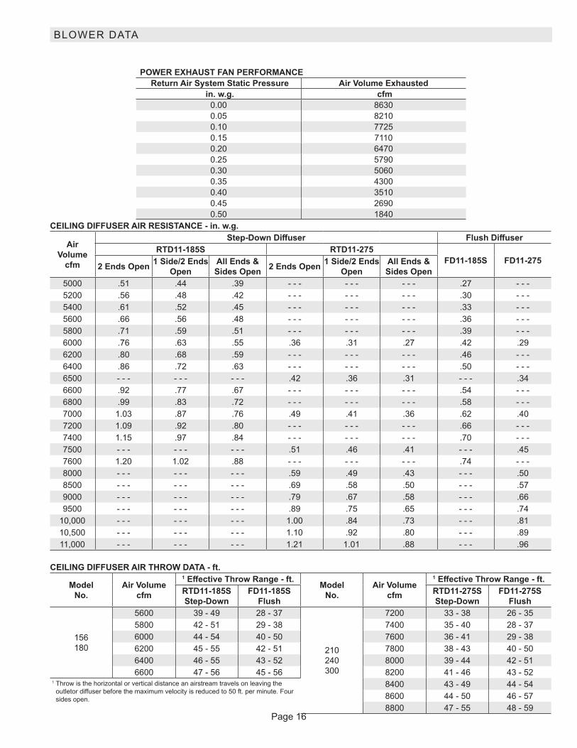
POWER EXHAUST FAN PERFORMANCE Return Air System Static Pressure Air Volume Exhausted
in. w.g. cfm 0.00 86300.05 82100.10 77250.15 71100.20 64700.25 57900.30 50600.35 43000.40 35100.45 26900.50 1840
CEILING DIFFUSER AIR RESISTANCE - in. w.g.
Air Volume
cfm
Step-Down Diffuser Flush DiffuserRTD11-185S RTD11-275
FD11-185S FD11-2752 Ends Open 1 Side/2 Ends Open
All Ends & Sides Open 2 Ends Open 1 Side/2 Ends
OpenAll Ends & Sides Open
5000 .51 .44 .39 - - - - - - - - - .27 - - -5200 .56 .48 .42 - - - - - - - - - .30 - - -5400 .61 .52 .45 - - - - - - - - - .33 - - -5600 .66 .56 .48 - - - - - - - - - .36 - - -5800 .71 .59 .51 - - - - - - - - - .39 - - -6000 .76 .63 .55 .36 .31 .27 .42 .296200 .80 .68 .59 - - - - - - - - - .46 - - -6400 .86 .72 .63 - - - - - - - - - .50 - - -6500 - - - - - - - - - .42 .36 .31 - - - .346600 .92 .77 .67 - - - - - - - - - .54 - - -6800 .99 .83 .72 - - - - - - - - - .58 - - -7000 1.03 .87 .76 .49 .41 .36 .62 .407200 1.09 .92 .80 - - - - - - - - - .66 - - -7400 1.15 .97 .84 - - - - - - - - - .70 - - -7500 - - - - - - - - - .51 .46 .41 - - - .457600 1.20 1.02 .88 - - - - - - - - - .74 - - -8000 - - - - - - - - - .59 .49 .43 - - - .508500 - - - - - - - - - .69 .58 .50 - - - .579000 - - - - - - - - - .79 .67 .58 - - - .669500 - - - - - - - - - .89 .75 .65 - - - .74
10,000 - - - - - - - - - 1.00 .84 .73 - - - .8110,500 - - - - - - - - - 1.10 .92 .80 - - - .8911,000 - - - - - - - - - 1.21 1.01 .88 - - - .96
CEILING DIFFUSER AIR THROW DATA - ft.
Model No.
Air Volume cfm
1 Effective Throw Range - ft. Model No.
Air Volume cfm
1 Effective Throw Range - ft.RTD11-185S Step-Down
FD11-185S Flush
RTD11-275S Step-Down
FD11-275S Flush
156 180
5600 39 - 49 28 - 37
210 240 300
7200 33 - 38 26 - 355800 42 - 51 29 - 38 7400 35 - 40 28 - 376000 44 - 54 40 - 50 7600 36 - 41 29 - 386200 45 - 55 42 - 51 7800 38 - 43 40 - 506400 46 - 55 43 - 52 8000 39 - 44 42 - 516600 47 - 56 45 - 56 8200 41 - 46 43 - 52
1 Throw is the horizontal or vertical distance an airstream travels on leaving the outletor diffuser before the maximum velocity is reduced to 50 ft. per minute. Four sides open.
8400 43 - 49 44 - 548600 44 - 50 46 - 578800 47 - 55 48 - 59
BLOWER DATA

Page 17
ELECTRICAL/ELECTRIC HEAT DATA 13 TON13 TON HIGH EFFICIENCY LCH156H41 Voltage - 60hz 208/230V - 3 Ph 460V - 3 Ph 575V - 3 Ph
Compressor 1 Rated Load Amps 14.5 6.3 6.0
Locked Rotor Amps 98 55 41
Compressor 2 Rated Load Amps 14.5 6.3 6
Locked Rotor Amps 98 55 41
Compressor 3 Rated Load Amps 14.5 6.3 6
Locked Rotor Amps 98 55 41
Outdoor FanMotors (3)
Full Load Amps(total)
2.4 (7.2)
1.3 3.9
1 (3)
Power Exhaust (2) 0.33 HP
Full Load Amps(total)
2.4 (4.8)
1.3 (2.6)
1 (2)
Service Outlet 115V GFI (amps) 15 15 20
Indoor Blower Motor
Horsepower 2 3 5 2 3 5 2 3 5
Full Load Amps 7.5 10.6 16.7 3.4 4.8 7.6 2.7 3.9 6.12 Maximum
Overcurrent Protection
Unit Only 70 70 80 30 35 35 30 30 30
With (2) 0.33 HP Power Exhaust
80 80 90 35 35 40 30 30 35
3 Minimum Circuit Ampacity
Unit Only 62 65 72 28 30 33 26 27 29
With (2) 0.33 HP Power Exhaust
67 70 77 31 32 35 28 29 31
ELECTRIC HEAT DATA
Electric Heat Voltage 208V 240V 208V 240V 208V 240V 480V 480V 480V 600V 600V 600V2 Maximum
Overcurrent Protection
Unit+ Electric Heat
15 kW 70 70 70 70 80 80 30 35 35 30 30 30
30 kW 4 90 100 4 100 110 4 100 125 50 60 60 40 45 45
45 kW 150 150 150 150 4 150 175 80 80 80 60 60 70
60 kW 4 150 175 4 150 175 4 150 175 80 80 90 70 70 703 Minimum
Circuit Ampacity
Unit+ Electric Heat
15 kW 62 62 65 65 72 72 28 30 33 26 27 29
30 kW 88 100 92 104 100 112 50 52 55 40 41 44
45 kW 127 145 131 149 139 157 72 74 78 58 60 62
60 kW 135 154 139 158 146 166 77 79 82 62 63 662 Maximum
Overcurrent Protection
Unit+ Electric Heat
and (2) 0.33 HP Power Exhaust
15 kW 80 80 80 80 90 90 35 35 40 30 30 35
30 kW 4 100 110 4 100 110 4 110 125 60 60 60 45 45 50
45 kW 4 150 175 4 150 175 4 150 175 80 80 90 70 70 70
60 kW 4 150 175 4 150 175 175 175 80 90 90 70 70 703 Minimum
Circuit Ampacity
Unit+ Electric Heat
and (2) 0.33 HP Power Exhaust
15 kW 67 67 70 70 77 77 31 32 36 28 29 31
30 kW 94 106 98 110 106 118 53 55 58 42 44 47
45 kW 133 151 137 155 145 163 76 77 81 61 62 65
60 kW 141 160 145 164 152 172 80 82 85 64 66 68NOTE - All units have a minimum Short Circuit Current Rating (SCCR) of 5000 amps.1 Extremes of operating range are plus and minus 10% of line voltage.2 HACR type breaker or fuse.3 Refer to National or Canadian Electrical Code manual to determine wire, fuse and disconnect size requirements.4 Factory installed circuit breaker not available.

Page 18
ELECTRICAL/ELECTRIC HEAT DATA 15 TON15 TON HIGH EFFICIENCY LCH180H41 Voltage - 60hz 208/230V - 3 Ph 460V - 3 Ph 575V - 3 Ph
Compressor 1 Rated Load Amps 13.2 6.3 4.9
Locked Rotor Amps 93 60 41
Compressor 2 Rated Load Amps 13.2 6.3 4.9
Locked Rotor Amps 93 60 41
Compressor 3 Rated Load Amps 13.2 6.3 4.9
Locked Rotor Amps 93 60 41
Outdoor FanMotors (8)
Full Load Amps(total)
2.4 (9.6)
1.3 (5.2)
1 (4)
Power Exhaust (2) 0.33 HP
Full Load Amps(total)
2.4 (4.8)
1.3 (2.6)
1 (2)
Service Outlet 115V GFI (amps) 15 15 20
Indoor Blower Motor
Horsepower 3 5 7.5 3 5 7.5 3 5 7.5
Full Load Amps 10.6 16.7 24.2 4.8 7.6 11 3.9 6.1 92 Maximum
Overcurrent Protection
Unit Only 70 80 100 35 40 45 25 30 35
With (2) 0.33 HP Power Exhaust
80 90 100 35 40 50 30 30 40
3 Minimum Circuit Ampacity
Unit Only 64 71 80 31 34 38 24 27 30
With (2) 0.33 HP Power Exhaust
68 75 85 34 37 41 26 29 32
ELECTRIC HEAT DATA
Electric Heat Voltage 208V 240V 208V 240V 208V 240V 480V 480V 480V 600V 600V 600V2 Maximum
Overcurrent Protection
Unit+ Electric Heat
15 kW 70 70 80 80 100 100 35 40 45 25 30 35
30 kW 4 100 110 4 100 125 4 110 125 60 60 60 45 45 50
45 kW 150 150 4 150 175 4 150 175 80 80 90 60 70 70
60 kW 4 150 175 4 150 175 175 175 80 90 90 70 70 703 Minimum
Circuit Ampacity
Unit+ Electric Heat
15 kW 64 64 71 71 80 80 31 34 38 24 27 30
30 kW 92 104 100 112 109 121 52 55 59 41 44 48
45 kW 131 149 139 157 148 166 74 78 82 60 62 66
60 kW 139 158 146 166 156 175 79 82 86 63 66 692 Maximum
Overcurrent Protection
Unit+ Electric Heat
and (2) 0.33 HP Power Exhaust
15 kW 80 80 90 90 100 100 35 40 50 30 30 40
30 kW 4 100 110 4 110 125 4 125 150 60 60 70 45 50 50
45 kW 4 150 175 4 150 175 175 175 80 90 90 70 70 70
60 kW 4 150 175 175 175 4 175 200 90 90 90 70 70 803 Minimum
Circuit Ampacity
Unit+ Electric Heat
and (2) 0.33 HP Power Exhaust
15 kW 68 68 75 75 85 85 34 37 41 26 29 32
30 kW 98 110 106 118 115 127 55 58 63 44 47 50
45 kW 137 155 145 163 154 172 77 81 85 62 65 68
60 kW 145 164 152 172 162 181 82 85 90 66 68 72NOTE - All units have a minimum Short Circuit Current Rating (SCCR) of 5000 amps.1 Extremes of operating range are plus and minus 10% of line voltage.2 HACR type breaker or fuse.3 Refer to National or Canadian Electrical Code manual to determine wire, fuse and disconnect size requirements.4 Factory installed circuit breaker not available.

Page 19
ELECTRICAL/ELECTRIC HEAT DATA 17.5 TON17.5 TON HIGH EFFICIENCY LCH210H4B/M1 Voltage - 60hz 208/230V - 3 Ph 460V - 3 Ph 575V - 3 PhCompressor 1 Rated Load Amps 15.6 7.8 5.8
Locked Rotor Amps 110 52 38.9
Compressor 2 Rated Load Amps 15.6 7.8 5.8
Locked Rotor Amps 110 52 38.9
Compressor 3 Rated Load Amps 19.6 8.2 6.6
Locked Rotor Amps 136 66.1 55.3
Outdoor Fan Motors (3)
Full Load Amps(total)
2.4 (14.4)
1.3 (7.8)
1 (6)
Power Exhaust (2) 0.33 HP
Full Load Amps(total)
2.4 (4.8)
1.3 (2.6)
1 (2)
Service Outlet 115V GFI (amps) 15 15 15
Indoor Blower Motor
Horsepower 3 5 7.5 3 5 7.5 3 5 7.5
Full Load Amps 10.6 16.7 24.2 4.8 7.6 11 3.9 6.1 92 Maximum
Overcurrent Protection
Unit Only 100 100 110 45 45 50 35 35 40
With (2) 0.33 HP Power Exhaust
100 110 110 45 50 50 35 40 45
3 Minimum Circuit Ampacity
Unit Only 81 87 96 39 42 46 30 32 36
With (2) 0.33 HP Power Exhaust
86 92 101 42 44 48 32 34 38
ELECTRIC HEAT DATA
Electric Heat Voltage 208V 240V 208V 240V 208V 240V 480V 480V 480V 600V 600V 600V2 Maximum
Overcurrent Protection
Unit+ Electric Heat
15 kW 100 100 100 100 110 110 45 45 50 35 35 40
30 kW 4 100 110 4 100 125 4 110 125 60 60 60 45 45 50
45 kW 150 150 4 150 175 4 150 175 80 80 90 60 70 70
60 kW 4 150 175 4 150 175 175 175 80 90 90 70 70 70
90 kW 4 225 250 4 225 250 4 225 250 125 125 125 100 100 1003 Minimum
Circuit Ampacity
Unit+ Electric Heat
15 kW 81 81 87 87 96 96 39 42 46 30 32 36
30 kW 92 104 100 112 109 121 52 55 59 41 44 48
45 kW 131 149 139 157 148 166 74 78 82 60 62 66
60 kW 139 158 146 166 156 175 79 82 86 63 66 69
90 kW 201 230 209 238 218 247 115 118 123 92 95 982 Maximum
Overcurrent Protection
Unit+ Electric Heat
and (2) 0.33 HP Power Exhaust
15 kW 100 100 110 110 110 110 45 50 50 35 40 45
30 kW 4 100 110 4 110 125 4 125 150 60 60 70 45 50 50
45 kW 4 150 175 4 150 175 175 175 80 90 90 70 70 70
60 kW 4 150 175 175 175 4 175 200 90 90 90 70 70 80
90 kW 4 225 250 4 225 250 4 225 4 300 125 125 150 100 100 1103 Minimum
Circuit Ampacity
Unit+ Electric Heat
and (2) 0.33 HP Power Exhaust
15 kW 86 86 92 92 101 101 42 44 48 32 34 38
30 kW 98 110 106 118 115 127 55 58 63 44 47 50
45 kW 137 155 145 163 154 172 77 81 85 62 65 68
60 kW 145 164 152 172 162 181 82 85 90 66 68 72
90 kW 207 236 215 244 224 253 118 122 126 94 97 101NOTE - All units have a minimum Short Circuit Current Rating (SCCR) of 5000 amps.1 Extremes of operating range are plus and minus 10% of line voltage.2 HACR type breaker or fuse.3 Refer to National or Canadian Electrical Code manual to determine wire, fuse and disconnect size requirements.4 Factory installed circuit breaker not available.

Page 20
ELECTRICAL/ELECTRIC HEAT DATA 20 TON20 TON HIGH EFFICIENCY LCH240H41 Voltage - 60hz 208/230V - 3 Ph 460V - 3 Ph 575V - 3 PhCompressor 1 Rated Load Amps 13.2 6.3 4.9
Locked Rotor Amps 93 60 41Compressor 2 Rated Load Amps 13.2 6.3 4.9
Locked Rotor Amps 93 60 41Compressor 3 Rated Load Amps 13.2 6.3 4.9
Locked Rotor Amps 93 60 41Compressor 4 Rated Load Amps 13.2 6.3 4.9
Locked Rotor Amps 93 60 41Outdoor Fan Motors (6)
Full Load Amps(total)
2.4 (14.4)
1.3 (7.8)
1 (6)
Power Exhaust (2) 0.33 HP
Full Load Amps(total)
2.4 (4.8)
1.3 (2.6)
1 (2)
Service Outlet 115V GFI (amps) 15 15 20Indoor Blower Motor
Horsepower 5 7.5 10 5 7.5 10 5 7.5 10Full Load Amps 16.7 24.2 30.8 7.6 11 14 6.1 9 11
2 Maximum Overcurrent Protection
Unit Only 100 110 125 50 50 60 35 45 50With (2) 0.33 HP
Power Exhaust100 125 125 50 60 60 40 45 50
3 Minimum Circuit Ampacity
Unit Only 89 98 106 43 47 51 34 37 40With (2) 0.33 HP
Power Exhaust93 103 111 46 50 54 36 39 42
ELECTRIC HEAT DATA
Electric Heat Voltage 208V 240V 208V 240V 208V 240V 480V 480V 480V 600V 600V 600V2 Maximum
Overcurrent Protection
Unit+ Electric Heat
15 kW 100 100 110 110 125 125 50 50 60 35 45 5030 kW 4 100 125 4 110 125 4 125 150 60 60 70 45 50 5045 kW 4 150 175 4 150 175 175 175 80 90 90 70 70 7060 kW 4 150 175 175 175 4 175 200 90 90 90 70 70 8090 kW 4 225 250 4 225 250 4 250 4 300 125 125 150 100 100 110
3 Minimum Circuit Ampacity
Unit+ Electric Heat
15 kW 89 89 98 98 106 106 43 47 51 34 37 4030 kW 100 112 109 121 117 129 55 59 63 44 48 5045 kW 139 157 148 166 156 174 78 82 86 62 66 6860 kW 146 166 156 175 164 183 82 86 90 66 69 7290 kW 209 238 218 247 227 256 118 123 126 95 98 101
2 Maximum Overcurrent Protection
Unit+ Electric Heat
and (2) 0.33 HP Power Exhaust
15 kW 100 100 125 125 125 125 50 60 60 40 45 5030 kW 4 110 125 4 125 150 4 125 150 60 70 70 50 50 6045 kW 4 150 175 175 175 4 175 200 90 90 90 70 70 8060 kW 175 175 4 175 200 4 175 200 90 90 100 70 80 8090 kW 4 225 250 4 225 4 300 4 250 4 300 125 150 150 100 110 110
3 Minimum Circuit Ampacity
Unit+ Electric Heat
and (2) 0.33 HP Power Exhaust
15 kW 93 93 103 103 111 111 46 50 54 36 39 4230 kW 106 118 115 127 123 135 58 63 66 47 50 5345 kW 145 163 154 172 162 180 81 85 89 65 68 7160 kW 152 172 162 181 170 189 85 90 93 68 72 7490 kW 215 244 224 253 233 262 122 126 130 97 101 103
NOTE - All units have a minimum Short Circuit Current Rating (SCCR) of 5000 amps.1 Extremes of operating range are plus and minus 10% of line voltage.2 HACR type breaker or fuse.3 Refer to National or Canadian Electrical Code manual to determine wire, fuse and disconnect size requirements.4 Factory installed circuit breaker not available.
Page 21
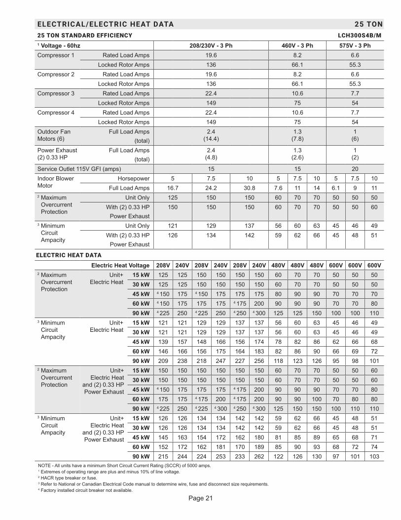
ELECTRICAL/ELECTRIC HEAT DATA 25 TON25 TON STANDARD EFFICIENCY LCH300S4B/M1 Voltage - 60hz 208/230V - 3 Ph 460V - 3 Ph 575V - 3 PhCompressor 1 Rated Load Amps 19.6 8.2 6.6
Locked Rotor Amps 136 66.1 55.3Compressor 2 Rated Load Amps 19.6 8.2 6.6
Locked Rotor Amps 136 66.1 55.3Compressor 3 Rated Load Amps 22.4 10.6 7.7
Locked Rotor Amps 149 75 54Compressor 4 Rated Load Amps 22.4 10.6 7.7
Locked Rotor Amps 149 75 54Outdoor Fan Motors (6)
Full Load Amps(total)
2.4 (14.4)
1.3 (7.8)
1 (6)
Power Exhaust (2) 0.33 HP
Full Load Amps(total)
2.4 (4.8)
1.3 (2.6)
1 (2)
Service Outlet 115V GFI (amps) 15 15 20Indoor Blower Motor
Horsepower 5 7.5 10 5 7.5 10 5 7.5 10Full Load Amps 16.7 24.2 30.8 7.6 11 14 6.1 9 11
2 Maximum Overcurrent Protection
Unit Only 125 150 150 60 70 70 50 50 50With (2) 0.33 HP
Power Exhaust150 150 150 60 70 70 50 50 60
3 Minimum Circuit Ampacity
Unit Only 121 129 137 56 60 63 45 46 49With (2) 0.33 HP
Power Exhaust126 134 142 59 62 66 45 48 51
ELECTRIC HEAT DATA
Electric Heat Voltage 208V 240V 208V 240V 208V 240V 480V 480V 480V 600V 600V 600V2 Maximum
Overcurrent Protection
Unit+ Electric Heat
15 kW 125 125 150 150 150 150 60 70 70 50 50 5030 kW 125 125 150 150 150 150 60 70 70 50 50 5045 kW 4 150 175 4 150 175 175 175 80 90 90 70 70 7060 kW 4 150 175 175 175 4 175 200 90 90 90 70 70 8090 kW 4 225 250 4 225 250 4 250 4 300 125 125 150 100 100 110
3 Minimum Circuit Ampacity
Unit+ Electric Heat
15 kW 121 121 129 129 137 137 56 60 63 45 46 4930 kW 121 121 129 129 137 137 56 60 63 45 46 4945 kW 139 157 148 166 156 174 78 82 86 62 66 6860 kW 146 166 156 175 164 183 82 86 90 66 69 7290 kW 209 238 218 247 227 256 118 123 126 95 98 101
2 Maximum Overcurrent Protection
Unit+ Electric Heat
and (2) 0.33 HP Power Exhaust
15 kW 150 150 150 150 150 150 60 70 70 50 50 6030 kW 150 150 150 150 150 150 60 70 70 50 50 6045 kW 4 150 175 175 175 4 175 200 90 90 90 70 70 8060 kW 175 175 4 175 200 4 175 200 90 90 100 70 80 8090 kW 4 225 250 4 225 4 300 4 250 4 300 125 150 150 100 110 110
3 Minimum Circuit Ampacity
Unit+ Electric Heat
and (2) 0.33 HP Power Exhaust
15 kW 126 126 134 134 142 142 59 62 66 45 48 5130 kW 126 126 134 134 142 142 59 62 66 45 48 5145 kW 145 163 154 172 162 180 81 85 89 65 68 7160 kW 152 172 162 181 170 189 85 90 93 68 72 7490 kW 215 244 224 253 233 262 122 126 130 97 101 103
NOTE - All units have a minimum Short Circuit Current Rating (SCCR) of 5000 amps.1 Extremes of operating range are plus and minus 10% of line voltage.2 HACR type breaker or fuse.3 Refer to National or Canadian Electrical Code manual to determine wire, fuse and disconnect size requirements.4 Factory installed circuit breaker not available.

Page 22
ELECTRICAL/ELECTRIC HEAT DATA 15 TON15 TON ULTRA HIGH EFFICIENCY (R-410A) LCH180U4M1 Voltage - 60hz 208/230V - 3 Ph 460V - 3 Ph 575V - 3 PhCompressor 1 Rated Load Amps 13.1 6.1 4.4
Locked Rotor Amps 83.1 41 33Compressor 2 Rated Load Amps 13.1 6.1 4.4
Locked Rotor Amps 83.1 41 33Compressor 3 Rated Load Amps 13.1 6.1 4.4
Locked Rotor Amps 83.1 41 33Compressor 4 Rated Load Amps 13.1 6.1 4.4
Locked Rotor Amps 83.1 41 33Outdoor FanMotors (6)
Full Load Amps (total)
2.8 (16.8)
1.4 (8.4)
1.1 (6.6)
Power Exhaust (2) 0.33 HP
Full Load Amps (total)
2.4 (4.8)
1.3 (2.6)
1 (2)
Service Outlet 115V GFI (amps) 15 15 20Indoor Blower Motor
Horsepower 3 5 7.5 3 5 7.5 3 5 7.5Full Load Amps 10.6 16.7 24.2 4.8 7.6 11 3.9 6.1 9
2 Maximum Overcurrent Protection
Unit Only 90 100 110 45 45 50 30 35 40With (2) 0.33 HP
Power Exhaust100 110 125 45 50 60 35 35 45
3 Minimum Circuit Ampacity
Unit Only 84 91 100 40 43 47 30 32 36With (2) 0.33 HP
Power Exhaust88 95 105 42 45 50 32 34 38
ELECTRIC HEAT DATAElectric Heat Voltage 208V 240V 208V 240V 208V 240V 480V 480V 480V 600V 600V 600V
2 Maximum Overcurrent Protection
Unit+ Electric Heat
15 kW 90 90 100 100 110 110 45 45 50 30 35 4030 kW 4 100 110 4 100 125 4 110 125 60 60 60 45 45 5045 kW 150 150 4 150 175 4 150 175 80 80 90 60 70 7060 kW 4 150 175 4 150 175 175 175 80 90 90 70 70 70
3 Minimum Circuit Ampacity
Unit+ Electric Heat
15 kW 84 84 91 91 100 100 40 43 47 30 32 3630 kW 92 104 100 112 109 121 52 55 59 41 44 4845 kW 131 149 139 157 148 166 74 78 82 60 62 6660 kW 139 158 146 166 156 175 79 82 86 63 66 69
2 Maximum Overcurrent Protection
Unit+ Electric Heat
and (2) 0.33 HP Power Exhaust
15 kW 100 100 110 110 125 125 45 50 60 35 35 4530 kW 4 100 110 4 110 125 4 125 150 60 60 70 45 50 5045 kW 4 150 175 4 150 175 175 175 80 90 90 70 70 7060 kW 4 150 175 175 175 4 175 200 90 90 90 70 70 80
3 Minimum Circuit Ampacity
Unit+ Electric Heat
and (2) 0.33 HP Power Exhaust
15 kW 88 88 95 95 105 105 42 45 50 32 34 3830 kW 98 110 106 118 115 127 55 58 63 44 47 5045 kW 137 155 145 163 154 172 77 81 85 62 65 6860 kW 145 164 152 172 162 181 82 85 90 66 68 72
NOTE - All units have a minimum Short Circuit Current Rating (SCCR) of 5000 amps.1 Extremes of operating range are plus and minus 10% of line voltage.2 HACR type breaker or fuse.3 Refer to National or Canadian Electrical Code manual to determine wire, fuse and disconnect size requirements.4 Factory installed circuit breaker not available.

Page 23
ELECTRICAL/ELECTRIC HEAT DATA 20 TON20 TON ULTRA HIGH EFFICIENCY (R-410A) LCH240U4M1 Voltage - 60hz 208/230V - 3 Ph 460V - 3 Ph 575V - 3 PhCompressor 1 Rated Load Amps 13.5 8 5
Locked Rotor Amps 109 59 40Compressor 2 Rated Load Amps 13.5 8 5
Locked Rotor Amps 109 59 40Compressor 3 Rated Load Amps 13.5 8 5
Locked Rotor Amps 109 59 40Compressor 4 Rated Load Amps 13.5 8 5
Locked Rotor Amps 109 59 40Outdoor Fan Motors (6)
Full Load Amps (total)
2.8 (16.8)
1.4 (8.4)
1.1 (6.6)
Power Exhaust (2) 0.33 HP
Full Load Amps (total)
2.4 (4.8)
1.3 (2.6)
1 (2)
Service Outlet 115V GFI (amps) 15 15 20Indoor Blower Motor
Horsepower 5 7.5 10 5 7.5 10 5 7.5 10Full Load Amps 16.7 24.2 30.8 7.6 11 14 6.1 9 11
2 Maximum Overcurrent Protection
Unit Only 100 125 125 50 60 70 40 45 50With (2) 0.33 HP
Power Exhaust110 125 125 60 60 70 40 45 50
3 Minimum Circuit Ampacity
Unit Only 92 102 110 50 55 58 35 38 41With (2) 0.33 HP
Power Exhaust97 106 115 53 57 61 37 40 43
ELECTRIC HEAT DATAElectric Heat Voltage 208V 240V 208V 240V 208V 240V 480V 480V 480V 600V 600V 600V
2 Maximum Overcurrent Protection
Unit+ Electric Heat
15 kW 100 100 125 125 125 125 50 60 70 40 45 5030 kW 4 100 125 125 125 4 125 150 60 60 70 45 50 5045 kW 4 150 175 4 150 175 175 175 80 90 90 70 70 7060 kW 4 150 175 175 175 4 175 200 90 90 90 70 70 8090 kW 4 225 250 4 225 250 4 250 4 300 125 125 150 100 100 110
3 Minimum Circuit Ampacity
Unit+ Electric Heat
15 kW 92 92 102 102 110 110 50 55 58 35 38 4130 kW 100 112 109 121 117 129 55 59 63 44 48 5045 kW 139 157 148 166 156 174 78 82 86 62 66 6860 kW 146 166 156 175 164 183 82 86 90 66 69 7290 kW 209 238 218 247 227 256 118 123 126 95 98 101
2 Maximum Overcurrent Protection
Unit+ Electric Heat
and (2) 0.33 HP Power Exhaust
15 kW 110 110 125 125 125 125 60 60 70 40 45 5030 kW 4 110 125 4 125 150 4 125 150 60 70 70 50 50 6045 kW 4 150 175 175 175 4 175 200 90 90 90 70 70 8060 kW 175 175 4 175 200 4 175 200 90 90 100 70 80 8090 kW 4 225 250 4 225 4 300 4 250 4 300 125 150 150 100 110 110
3 Minimum Circuit Ampacity
Unit+ Electric Heat
and (2) 0.33 HP Power Exhaust
15 kW 97 97 106 106 115 115 53 57 61 37 40 4330 kW 106 118 115 127 123 135 58 63 66 47 50 5345 kW 145 163 154 172 162 180 81 85 89 65 68 7160 kW 152 172 162 181 170 189 85 90 93 68 72 7490 kW 215 244 224 253 233 262 122 126 130 97 101 103
NOTE - All units have a minimum Short Circuit Current Rating (SCCR) of 5000 amps.1 Extremes of operating range are plus and minus 10% of line voltage.2 HACR type breaker or fuse.3 Refer to National or Canadian Electrical Code manual to determine wire, fuse and disconnect size requirements.4 Factory installed circuit breaker not available.
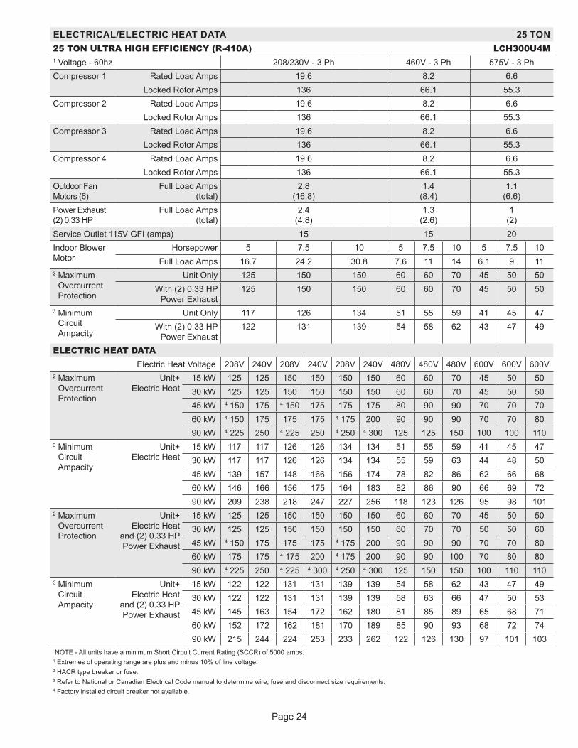
Page 24
ELECTRICAL/ELECTRIC HEAT DATA 25 TON25 TON ULTRA HIGH EFFICIENCY (R-410A) LCH300U4M1 Voltage - 60hz 208/230V - 3 Ph 460V - 3 Ph 575V - 3 PhCompressor 1 Rated Load Amps 19.6 8.2 6.6
Locked Rotor Amps 136 66.1 55.3Compressor 2 Rated Load Amps 19.6 8.2 6.6
Locked Rotor Amps 136 66.1 55.3Compressor 3 Rated Load Amps 19.6 8.2 6.6
Locked Rotor Amps 136 66.1 55.3Compressor 4 Rated Load Amps 19.6 8.2 6.6
Locked Rotor Amps 136 66.1 55.3Outdoor Fan Motors (6)
Full Load Amps (total)
2.8 (16.8)
1.4 (8.4)
1.1 (6.6)
Power Exhaust (2) 0.33 HP
Full Load Amps (total)
2.4 (4.8)
1.3 (2.6)
1 (2)
Service Outlet 115V GFI (amps) 15 15 20Indoor Blower Motor
Horsepower 5 7.5 10 5 7.5 10 5 7.5 10Full Load Amps 16.7 24.2 30.8 7.6 11 14 6.1 9 11
2 Maximum Overcurrent Protection
Unit Only 125 150 150 60 60 70 45 50 50With (2) 0.33 HP
Power Exhaust125 150 150 60 60 70 45 50 50
3 Minimum Circuit Ampacity
Unit Only 117 126 134 51 55 59 41 45 47With (2) 0.33 HP
Power Exhaust122 131 139 54 58 62 43 47 49
ELECTRIC HEAT DATAElectric Heat Voltage 208V 240V 208V 240V 208V 240V 480V 480V 480V 600V 600V 600V
2 Maximum Overcurrent Protection
Unit+ Electric Heat
15 kW 125 125 150 150 150 150 60 60 70 45 50 5030 kW 125 125 150 150 150 150 60 60 70 45 50 5045 kW 4 150 175 4 150 175 175 175 80 90 90 70 70 7060 kW 4 150 175 175 175 4 175 200 90 90 90 70 70 8090 kW 4 225 250 4 225 250 4 250 4 300 125 125 150 100 100 110
3 Minimum Circuit Ampacity
Unit+ Electric Heat
15 kW 117 117 126 126 134 134 51 55 59 41 45 4730 kW 117 117 126 126 134 134 55 59 63 44 48 5045 kW 139 157 148 166 156 174 78 82 86 62 66 6860 kW 146 166 156 175 164 183 82 86 90 66 69 7290 kW 209 238 218 247 227 256 118 123 126 95 98 101
2 Maximum Overcurrent Protection
Unit+ Electric Heat
and (2) 0.33 HP Power Exhaust
15 kW 125 125 150 150 150 150 60 60 70 45 50 5030 kW 125 125 150 150 150 150 60 70 70 50 50 6045 kW 4 150 175 175 175 4 175 200 90 90 90 70 70 8060 kW 175 175 4 175 200 4 175 200 90 90 100 70 80 8090 kW 4 225 250 4 225 4 300 4 250 4 300 125 150 150 100 110 110
3 Minimum Circuit Ampacity
Unit+ Electric Heat
and (2) 0.33 HP Power Exhaust
15 kW 122 122 131 131 139 139 54 58 62 43 47 4930 kW 122 122 131 131 139 139 58 63 66 47 50 5345 kW 145 163 154 172 162 180 81 85 89 65 68 7160 kW 152 172 162 181 170 189 85 90 93 68 72 7490 kW 215 244 224 253 233 262 122 126 130 97 101 103
NOTE - All units have a minimum Short Circuit Current Rating (SCCR) of 5000 amps.1 Extremes of operating range are plus and minus 10% of line voltage.2 HACR type breaker or fuse.3 Refer to National or Canadian Electrical Code manual to determine wire, fuse and disconnect size requirements.4 Factory installed circuit breaker not available.

Page 25
ELECTRIC HEAT CAPACITIES
Volts Input
15 kW 30 kW 45 kW 60 kW 90 kWkW
Input Btuh
Output No. of Stages
kW Input
Btuh Output
No. of Stages
kW Input
Btuh Output
No. of Stages
kW Input
Btuh Output
No. of Stages
kW Input
Btuh Output
No. of Stages
208 11.3 38,600 1 22.5 76,800 1 33.8 115,300 2 45.0 153,600 2 67.6 230,700 2 220 12.6 43,000 1 25.2 86,000 1 37.8 129,000 2 50.4 172,000 2 75.6 258,000 2 230 13.8 47,100 1 27.5 93,900 1 41.3 141,000 2 55.1 188,000 2 82.7 282,200 2 240 15.0 51,200 1 30.0 102,400 1 45.0 153,600 2 60.0 204,800 2 90.0 307,100 2 440 12.6 43,000 1 25.2 86,000 1 37.8 129,000 2 50.4 172,000 2 75.6 258,000 2 460 13.8 47,100 1 27.5 93,900 1 41.3 141,000 2 55.1 188,000 2 82.7 282,200 2 480 15.0 51,200 1 30.0 102,400 1 45.0 153,600 2 60.0 204,800 2 90.0 307,100 2 550 12.6 43,000 1 25.2 86,000 1 37.8 129,000 2 50.4 172,000 2 75.6 258,000 2 575 13.8 47,100 1 27.5 93,900 1 41.3 141,000 2 55.1 188,000 2 82.7 282,200 2 600 15.0 51,200 1 30.0 102,400 1 45.0 153,600 2 60.0 204,800 2 90.0 307,100 2

Pag
e 2
6
CONTROL BOX PARTS ARRANGEMENT
FIGURE 1
A55
A59
K3 S42
K65

Pag
e 2
7
CONTROL BOX PARTS ARRANGEMENT(ADD ONS FOR 180U & 240U, 300U)
FIGURE 2
COMPRESSOR1 CONTACTOR
(K1)
COMPRESSOR2 CONTACTOR
(K2)
COMPRESSOR3 CONTACTOR
(K14)
COMPRESSOR4 CONTACTOR
(K146)
BLOWER MOTOROVERLOAD RELAY
(S42)
BLOWER CONTACTORRELAY (K3)
TERMINALBLOCK (TB13)
CONTROLTRANSFORMER
(T1)
POWER EXHAUSTRELAY (K65)(PED ONLY)
OUTDOOR FANMOTOR FUSEBLOCK (F10)
CONTACTORTRANSFORMER
(T18)CONTROL MODULE
C3 (A178)
EXHAUST FANMOTOR FUSEBLOCK (F6)
THERMOSTATCONNECTIONS
(J297)
CONTROL MODULE (A55, M3)
OUTDOOR FAN
TRANSFORMERS (4)
CRANKCASEHEATER RELAY (4)
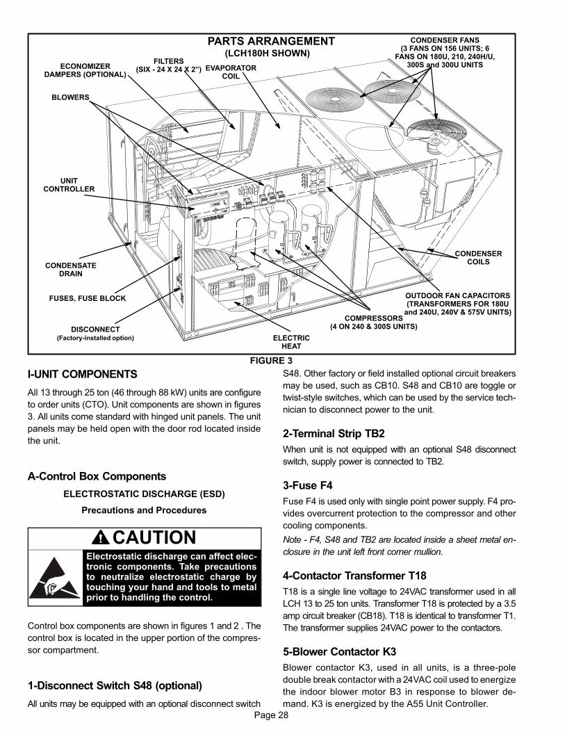
Page 28
PARTS ARRANGEMENT(LCH180H SHOWN)
FIGURE 3
CONDENSERCOILS
ELECTRICHEAT
EVAPORATORCOIL
BLOWERS
FILTERS(SIX - 24 X 24 X 2”)ECONOMIZER
DAMPERS (OPTIONAL)
CONDENSATEDRAIN
UNITCONTROLLER
DISCONNECT(Factory-installed option)
COMPRESSORS(4 ON 240 & 300S UNITS)
FUSES, FUSE BLOCK
CONDENSER FANS(3 FANS ON 156 UNITS; 6
FANS ON 180U, 210, 240H/U,300S and 300U UNITS
OUTDOOR FAN CAPACITORS(TRANSFORMERS FOR 180U
and 240U, 240V & 575V UNITS)
I-UNIT COMPONENTS
All 13 through 25 ton (46 through 88 kW) units are configure
to order units (CTO). Unit components are shown in figures
3. All units come standard with hinged unit panels. The unit
panels may be held open with the door rod located inside
the unit.
A-Control Box Components
ELECTROSTATIC DISCHARGE (ESD)
Precautions and Procedures
CAUTIONElectrostatic discharge can affect electronic components. Take precautionsto neutralize electrostatic charge bytouching your hand and tools to metalprior to handling the control.
Control box components are shown in figures 1 and 2 . The
control box is located in the upper portion of the compres
sor compartment.
1-Disconnect Switch S48 (optional)
All units may be equipped with an optional disconnect switch
S48. Other factory or field installed optional circuit breakers
may be used, such as CB10. S48 and CB10 are toggle or
twist-style switches, which can be used by the service tech
nician to disconnect power to the unit.
2-Terminal Strip TB2
When unit is not equipped with an optional S48 disconnect
switch, supply power is connected to TB2.
3-Fuse F4
Fuse F4 is used only with single point power supply. F4 pro
vides overcurrent protection to the compressor and other
cooling components.
Note - F4, S48 and TB2 are located inside a sheet metal en
closure in the unit left front corner mullion.
4-Contactor Transformer T18
T18 is a single line voltage to 24VAC transformer used in all
LCH 13 to 25 ton units. Transformer T18 is protected by a 3.5
amp circuit breaker (CB18). T18 is identical to transformer T1.
The transformer supplies 24VAC power to the contactors.
5-Blower Contactor K3
Blower contactor K3, used in all units, is a three-pole
double break contactor with a 24VAC coil used to energize
the indoor blower motor B3 in response to blower de
mand. K3 is energized by the A55 Unit Controller.

Page 29
6-Control Transformer T1
All use a single line voltage to 24VAC transformer
mounted in the control box. Transformer supplies power
to control circuits in the unit. The transformer is rated at
70VA and is protected by a 3.5 amp circuit breaker
(CB8). The 208/230 (Y) voltage transformers use two
primary voltage taps
as shown in figure 4,
while 460 (G) and 575
(J) voltage transform
ers use a single prima
ry voltage tap.
7-Terminal Block TB13
TB13 terminal block distributes line voltage power to the
line voltage items in the unit.
8-Outdoor Fan Motor Fuse Block & Fuses F10
Power Exhaust Fan Motor Fuse Block and
Fuses F6 (240 and 300 Y Volt Only)
Three line voltage fuses F10 provide overcurrent protec
tion to all condenser fans. Two line voltage fuses F6 pro
vide overcurrent protection to the two optional power ex
haust fans. The fuses are rated at 30A in all 208/230V
models but 10A in the 208/230V 240U and 300U model.
9-Outdoor Fan Capacitors C1, C2, C18, C19,C20, C21 (not used in 180U, 240U, 300U)
C1, C2, & C18: All units
C19: 180, 210, 240, 300 Units
C20 & C21: 210, 240, 300 Units
Fan capacitors C1, C2, C18, C19, C20 and C21 are 370V /
10 MFD capacitors used to assist in the start up of condens
er fans B4, B5, B21, B22, B23 and B24 respectively.
10-Outdoor Fan Transformers T5, T59 (460V &575V units)
All 460 (G) and 575 (J) voltage 180U, 240U and 300U units
use transformer T5 and T59. The auto voltage to 230VAC
transformers are mounted in the control box. The trans
formers have an output rating of 0.5A. T5 transformer sup
plies 230 VAC power to outdoor fans B4, B5 and B21. T13
transformer supplies 230V to outdoor fans B22, B23 and
B24.
11-Compressor Contactor K1, K2, K14, K146K1, K2, K14: All units
K146: 180, 240, 300
All compressor contactors are three‐pole‐double‐break
contactors with 24VAC coils. K1 and K2 (energized by A55)
energizes compressors B1 and B2 in response to first
stage cool demand. K14 and K146 (energized by A59) en
ergize compressors B13 and B20 in response to second
stage cool demand. In 180U, 240U and 300U units, K14
and K146 is energized by A178 in response to second
stage cool demand.
12-Outdoor Fan Relay K10, K68, K149, K150,
K152, K153
K10 & K68: All units
K149 & K150: 180, 210, 240, 300
K152 & K153: 210, 240, 300
Outdoor fan relays are DPDT relays with a 24VAC coil.
In 156 units, K10 energizes fan 1 B4 and K68 energizes fan
2 B5 and fan 3 B21.
In 180 units, K10 energizes fan 1 B4, K68 energizes fan 2 B5,
K149 energizes fan 3 B21 and K150 energizes fan 4 B22.
In 210, 240 and 300 units, K10 energizes fan 1 B4, K68 en
ergizes fan 2 B5, K149 energizes fan 3 B21, K150 ener
gizes fan 4 B22, K152 energizes fan 5 B23 and K153 ener
gizes fan 6 B24..
13-Ultraviolet Germicidal Lamp (UVC) Trans
former T49
UVC transformer T49 is used by units of all voltages except
208/230V and 575V which are equipped with a UVC. The
auto voltage to 230VAC transformer is installed in the con
trol box. The transformer has an output rating of 0.5 amps.
T49 transformer supplies 230VAC power to the UVC lamp.
14-Power Exhaust Relay K65 (PED units)
Power exhaust relay K65 is a N.O. DPDT relay with a
24VAC coil. K65 is used in units equipped with the optional
power exhaust dampers. K65 is energized by the A55 Unit
Controller, after the economizer dampers reach 50% open
(adjustable in ECTO). When K65 closes, the exhaust fans
B10 and B11 are energized.
15-Unit Controller A55
The Unit Controller provides all unit control functions, unit
status information, unit diagnostics, programmable pa
rameters and USB verification and profile sharing. Refer to
the Unit Controller guide provided with the unit. Thermostat
wires are connected to J297 on the Unit Controller.
16-Compressor 3 & 4 Controller A59 (not
used on (180U, 240U and 300U)
The compressor 3 & 4 control module A59 controls twoadditional compressor stages. A59 includes all inputs andoutputs required for compressor and fan control, compressor stage diagnostics and low ambient control.
FIGURE 4
230 VOLTS
208 VOLTS
PRIMARY
SECONDARY
208/230V TRANSFORMER

Page 30
17-Variable Frequency Drive A96 (optional)
MSAV units are equipped with a VFD which alters the sup
ply power frequency and voltage to the blower motor.
Blower speed is staged depending on the compressor
stages, heating demand, ventilation demand, or smoke
alarm. The amount of airflow for each stage is preset from
the factory. Airflow can be adjusted by changing ECTO pa
rameters in the A55 Unit Controller. The VFD is located
below the Unit Controller.
18-VFD Power To Motor Contactor K202
(optional)
Contactor is used in MSAV units equipped with a VFD by
pass option. The three‐pole 40 amp contactor with a 24VAC
coil is energized by the A55 Unit Controller. K202 allows
power from the VFD to the B3 blower motor in response to
blower demand.
19-Inverter Start Forward Rotation Relay K203
(optional)
Relay is used in optional MSAV units and is a three-pole
double-throw relay with a 24VAC coil. K203 is energized by
the A55 Unit Controller and provides input to the A96 VFD
to start blower forward rotation. K203 also de-energizes K3
allowing A96 to control B3 blower.
20-VFD Controller (GP board) A133 (MSAV
units)
The GP board A133 controls and monitors the status of the
VFD A96. The board sends the signal to start the VFD for
ward rotation and also sends a 0-10VDC signal to the VFD
to control the speed of the blower rotation. A133 also re
ports VFD malfunctions to the A55.
21-Second-Stage Power Exhaust Relay
K231 (MSAV units equipped with power
exhaust)
The second power exhaust fan is controlled by K231.
A133 will enable K231 only when the blower reaches 70%
of full speed (adjustable ECTO). This prevents a negative
building pressure when the blower is operating in low
speed. Refer to the Unit Controller manual and ECTO la
bels on the unit.
22-Electric Heat Relay K9
All unit equipped with optional electric heat use an electric heat relay K9. K9 is a N.O. SPST pilot relay intendedto electrically interlock operation of left and right sideelectric heat sections. K9 is energized by the A55 UnitController. K9-1 closes, energizing electric heat contactors K17 and K18.
23-Compressor 3 & 4 Controller A59 & A178
The compressor 3 & 4 control module A59 controls two ad
ditional compressor stages. A59 includes all inputs and
outputs required for compressor and fan control, compres
sor stage diagnostics and low ambient control.
The M3 unit controller is only compatible with L-Connectionsensors provided with the unit or purchased separately asspecified in the Product Specification. Tables 1 through 4show thermistor and pressure transducer readings.
Temperature Sensors
The return air (RT16) and discharge air (RT6) duct probesand the outdoor air (RT17) are all two wire thermistors. Theresistance vs. temperature table is shown below:
TABLE 1Resistance vs. Temperature
Temp. °F (°C) Resistance +/-2%Temperature °F
(°C)Resistance +/-2% Temp. °F (°C) Resistance +/-2%
-40 (-40) 335,671 40 (4.4) 26,106 90 (32.2) 7,332
-20 (-28.9) 164,959 50 (10) 19,904 100 (37.8) 5,826
0 (-17.8) 85,323 60 (15.6) 15,313 120 (48.9) 3,756
20 (-6.7) 46,218 70 (21.1) 11,884 130 (54.4) 3,047
30 (-1.1) 34,566 80 (26.7) 9,298

Page 31
Room Sensors
Room sensor (A2) is a two-wire thermistor with 1k series resistor.
TABLE 2Two-Wire Thermistor
Temp. °F (°C) Resistance +/-2%Temperature °F
(°C)Resistance +/-2% Temp. °F (°C) Resistance +/-2%
40 (4.4) 27,102 60 (15.6) 16,313 80 (26.7) 10,299
45 (7.2) 23,764 65 (18.3) 14,474 85 (29.4) 9,249
50 (10) 20,898 70 (21.1) 12,882 90 (32.2) 8,529
55 (12.8) 18,433 75 (23.9) 11,498
Carbon Dioxide Sensor
The indoor carbon dioxide sensor (A63) is an analog sensor with a 0-10VDC output over a carbon dioxide range of 0-2000ppm as shown in the following table. The sensor is powered with 24VAC.
TABLE 3Carbon Dioxide Range
Carbon DioxidePPM
DCV
Carbon DioxidePPM
DC VoltageCarbon Dioxide
PPMDC Voltage
Carbon DioxidePPM
DCV
0 0 600 3 1200 6 1800 9
200 1 800 4 1400 7 2000 10
400 2 1000 5 1600 8
VAV Supply Static Sensor
The supply duct differential static pressure sensor (A30) is an analog sensor with a 0-10VDC output over a range of 0-5"w.cas shown in the following table. The sensor is powered with 24VAC.
TABLE 4Static Pressure
Pressure "w.c. DC Voltage Pressure "w.c. DC Voltage Pressure "w.c. DC Voltage Pressure "w.c. DC Voltage
0 0 1.5 3 3 6 4.5 9
0.5 1 2 4 3.5 7 5 10
1 2 2.5 5 4 8
Relative Humidity Sensor - Optional
The indoor relative humidity sensor (A91) is an analog sensor with a 0-10VDC output over a relative humidity range of0-100% relative humidity. The sensor is powered with24VAC.
Enthalpy Sensor - Optional
The optional enthalpy sensors (A7 and A63) used with theeconomizer have an output of 4-20mA. The sensor is powered with 18VAC provided by M3 unit control.
Economizer Differential Pressure Sensor - Optional
Rooftop units installed with Smart Airflow™ will have aPressure Transducer (PT5) present in the economizer.PT5 requires 5VDC power supply (P266-5 and {P266-6)and gives 0.25 VDC to 4 VDC output (P266-4) corresponding to 0” water column and 2” water column respectively.For all practical purposes the output should be less than1.2” water column if not an error code is stored and servicealarm output is turned on.

Page 32
24-Blower Motor Overload Relay S42
Two hp high efficiency blower motors and M-volt unit blower
motors are equipped with an overload relay. High efficiency
blower motors and M-volt unit blower motors manufactured
before Dec. 19, 2010, are equipped with the relay.
The relay (S42) is connected in line with the blower motor
to monitor the current flow to the motor. When the relay
senses an overload condition, a set of normally closed
contacts open to de-energize pin #1 in plug P299 of the
A55 Unit Controller. A55 de-energizes all outputs. Units
will be equipped with a relay manufactured by Telemeca
nique figure 5 or Siemens figure 6.
CLEARCOVER
(SHOWNCLOSED)
STOPBUTTON
(RED)
RED TESTBUTTON
(Push To Test)
AMP SETTINGCONTROL
(BLUE DIAL)
TRIPINDICATION
WINDOW
LINE VOLTAGE IN
AMP SETTINGPOINTER
BLUE RESET SCREW(Shown in AUTO position as
shipped from the factory)LOAD VOLTAGE OUT
DETAIL SHOWING RESET BUTTONADJUSTED TO MANUAL POSITION
Lift clear cover and turn adjustment screwcounterclockwise. Reset screw will pop out
when pointer is in M (manual position). Closecover to lock reset screw into position.
TELEMECANIQUE OVERLOAD RELAY
Lift clear cover to adjust relay amp setting according to value given on the blower motor nameplate.Proper relay amp setting equals motor nameplate FLA X service factor of 1.15 X .95.
Cover must also be lifted to adjust control mode from automatic reset to manual reset (see detailabove) and to test the control.
Control must be in the manual reset mode to perform a test. Use a pointed object to press the smallred test button. A yellow marker should appear in the trip indication window to the right of the amp
setting control. Press the blue reset screw to reset the relay.The red STOP button opens the normally closed contacts which power the blower motor. This button
stops blower motor operation as long as it is pressed in.
FIGURE 5
SIEMENS OVERLOAD RELAY
Adjust relay amp setting according to value given on the blower motor nameplate. Proper relay ampsetting equals motor nameplate FLA X service factor of 1.15 X .95.
Use small slotted screwdriver to adjust control mode from automatic reset (A) to manual reset (H). Control must be in the manual reset mode (H) to perform a test. Press the red test button. Green trip
indicator should pop out. Press the blue reset screw to reset the relay.
BLUE RESET BUTTON INFACTORY‐SET AUTO MODE
(Turn clockwise to H formanual reset)
GREEN TRIP INDICATOR(Flush with surface -- not tripped;
Above surface -- tripped)
AMP ADJUSTMENT DIAL
RED TEST BUTTON
FIGURE 6
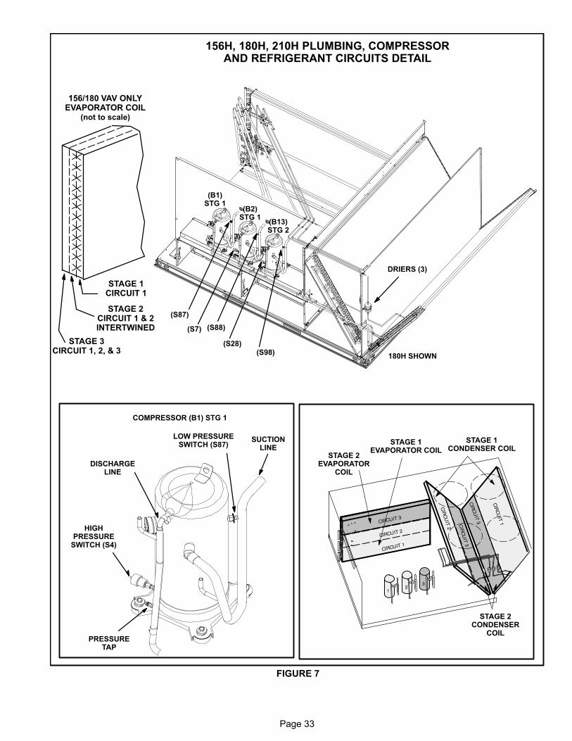
Page 33
156H, 180H, 210H PLUMBING, COMPRESSORAND REFRIGERANT CIRCUITS DETAIL
FIGURE 7
STAGE 1CONDENSER COIL
STAGE 2CONDENSER
COIL
STAGE 1EVAPORATOR COIL
STAGE 2EVAPORATOR
COIL
SUCTIONLINE
HIGHPRESSURE
SWITCH (S4)
DISCHARGELINE
PRESSURETAP
COMPRESSOR (B1) STG 1
LOW PRESSURESWITCH (S87)
(B2)STG 1
(B13)STG 2
(B1)STG 1
(S87)
(S7)
(S28)
(S88)
DRIERS (3)
(S98)180H SHOWN
156/180 VAV ONLYEVAPORATOR COIL
(not to scale)
STAGE 1CIRCUIT 1
STAGE 3CIRCUIT 1, 2, & 3
STAGE 2CIRCUIT 1 & 2INTERTWINED

Page 34
240H, 300S, 300U PLUMBING, COMPRESSORAND
REFRIGERANT CIRCUITS DETAIL
FIGURE 8
STAGE 1CONDENSER COIL
STAGE 2EVAPORATOR COIL
STAGE 2CONDENSER COIL
STAGE 1EVAPORATOR COIL
(B2)STG 1
(B13)STG 2
(B1)STG 1
(S87)
(S7)
(S28)
(S88)
(S96)
SUCTIONLINE
HIGHPRESSURE
SWITCH (S4)
DISCHARGELINE
PRESSURETAP
COMPRESSOR (B1) STG 1
LOW PRESSURESWITCH (S87)
(B20)STG 2
(S97)
(S98)
DRIERS (4)

Page 35
FIGURE 9
S8 (180 ONLY)COMPRESSOR 2 HIGH TEM
PERATURE SWITCH
S5 (180 ONLY)COMPRESSOR 1 HIGH
TEMPERATURE SWITCH
A185 STG. 1PRESSURE
TRANSDUCER
S87 STG. 1LOW PRESSURE
SWITCH
S31 (180 ONLY)COMPRESSOR 3 HIGH TEM
PERATURE SWITCH
S180 (180 ONLY)COMPRESSOR 4 HIGH
TEMPERATURE SWITCH
A186 STG. 2PRESSURE
TRANSDUCER
S98 STG. 2LOW PRESSURE SWITCH
S5 (240 ONLY)COMPRESSOR 1
HIGH TEMPERATURESWITCH
S8 (240 ONLY)COMPRESSOR 2 HIGHTEMPERATURE LIMIT
S31 (240 ONLY)COMPRESSOR 3 HIGHTEMPERATURE LIMIT
S180 (240 ONLY)COMPRESSOR 4 HIGH
TEMPERATURE SWITCH
CIRCUIT 1 AND 2ALTERNATE THROUGH THE
EVAPORATOR COIL(not to scale)
CIRCUIT 1CONDENSER COIL
180U, 240U & 300U REFRIGERANT CIRCUITS
CIRCUIT 2CONDENSER COIL
CIRCUIT 1 -COMPRESSOR 1 AND 2
CIRCUIT 2 -COMPRESSOR 3 AND 4
Y1=Compressor 1 or 2 AND Compressor 3 or 4Y2=Compressor 1, 2, 3, 4
180U, 240U & 300U COMPRESSOR DETAIL

Page 36
B-Cooling Components
All units use independent cooling circuits consisting of sep
arate compressors, condenser coils and evaporator coils.
See figure 7 for 156H, 180H and 210H units, figure 8 for
240H and 300S units and figure 9 for 180U, 240U and 300U
units.
Three draw-through type condenser fans are used in
LCH156 units, four draw-through type condenser fans are
used in LCH180 units and six draw-through type condens
er fans are used in LCH210, 240 and 300 units. All units are
equipped with belt‐drive blowers which draw air across the
evaporator during unit operation.
Cooling may be supplemented by a factory‐ or field‐
installed economizer. The evaporators are slab type and
are stacked. Each evaporator uses a thermostatic ex
pansion valve as the primary expansion device. Each
evaporator is also equipped with enhanced fins and rifled
tubing. In all units each compressor is protected by a crank
case heater, high pressure switch and low pressure switch.
Additional protection is provided by low ambient switches
and freezestats (on each evaporator).
1-Condenser Fans B4, B5, B21 (all units), B22
(180/300), B23, B24 (180U, 210/300)
See SPECIFICATIONS tables at the front of this manual
for specifications of condenser fans used in all units. All
condenser fans used have single-phase motors. The fan
assembly may be removed for servicing and cleaning.
2-Compressors B1, B2, B13 (all units) B20
(180U, 240, 300)
All units use scroll compressors. LCH156, 180 and 210 use
3 compressors and LCH240 and 300 use four compres
sors and LCH180U, 240 and 300 use four compressors.All
compressors are equipped with independent cooling cir
cuits. Compressor capacity may vary from stage to stage.
In all cases, the capacity of each compressor is added to
reach the total capacity of the unit. See “SPECIFICA
TIONS” and “ELECTRICAL DATA” (table of contents) or
compressor nameplate for compressor specifications.
WARNINGElectrical shock hazard. Compressor must begrounded. Do not operate without protective coverover terminals. Disconnect power before removingprotective cover. Discharge capacitors before servicing unit. Failure to follow these precautions couldcause electrical shock resulting in injury or death.
Each compressor is energized by a corresponding com
pressor contactor.
NOTE-Refer to the wiring diagram section for specific unit
operation.
If Interlink compressor replacement is necessary, call
1-800-453-6669.
IMPORTANTSome scroll compressors have an internal vacuumprotector that will unload scrolls when suctionpressure goes below 20 psig. A hissing sound willbe heard when the compressor is running unloaded. Protector will reset when low pressure insystem rises above 40 psig. DO NOT REPLACECOMPRESSOR.
3-Crankcase Heaters HR1, HR2, HR5 (all units)
HR11 (240, 300)
All LCH units use insertion type heaters. Heater HR1 is in
stalled around compressor B1, heater HR2 compressor B2,
HR5 compressor B13 and HR11 compressor B20.
4-High Pressure Switches S4, S7, S28, S96
S4 all units
S7 all standard and high efficiency units only
S28 all units
S96 240H and 300
The high pressure switches is an auto‐reset SPST N.C.
switch which opens on a pressure rise. All units are
equipped with this switch. The switch is located in the com
pressor discharge line and is wired in series with the com
pressor contactor coil through A55 Unit Controller or A59
Compressor 3 and 4 Controller.
S4 (first circuit), S7 (second circuit), S28 (third circuit) and
S96 (fourth circuit) are wired in series with the respective
compressor contactor coils.
When discharge pressure rises to 640 ± 10 psig (4413 ± 69
kPa) (indicating a problem in the system) the switch opens
and the respective compressor is de-energized (the econ
omizer can continue to operate). When discharge pressure
drops to 475 ± 20 psig (3275 ± 138 kPa) the pressure
switch will close.
Main control A55 has a three-strike counter before locking
out. This means the control allows three high pressure trips
per one thermostat demand. The control can be reset by
breaking and remaking the thermostat demand or manual
ly resetting the control.
5-Low Ambient Switches S11, S84, S85, S94
S11 all units
S84 all standard and high efficiency units only
S85 all units
S94 240H and 300
The low ambient switch is an auto‐reset SPST N.O. pres
sure switch which allows for mechanical cooling operation
at low outdoor temperatures. All units are equipped with
this switch. In all models a switch is located in each liquid
line prior to the indoor coil section.

Page 37
In LCH156/210 units, S11 (compressor one) is wired to the
Unit Controller (A55) and S84 (compressor two) and S85
(compressor three) are wired in parallel to the Unit Con
troller. In LCH240/300 units, S11 (compressor one) and
S84 (compressor 2) are wired in parallel to the Unit Con
troller; S85 (compressor 3) and S94 (compressor four) are
wired in parallel to the Unit Controller.
When liquid pressure rises to 450 ± 10 psig (3102 ± 69
kPa), the switch closes. When liquid pressure drops to 240
± 10 psig (1655 ± 69 kPa), the switch opens and the Unit
Controller will cycle condenser fans via the following out
door fan relays:
K10 and K68 (156H, 180H, 210H, 300)
K149 and K150 (180H, 210, 240H, 300 units)
K152 and K153 (180U, 210, 240, 300 units)
The Unit Controller cycles fans based on the low ambient
pressure switch inputs and outdoor ambient temperature.
This intermittent fan operation results in higher evaporating
temperature allowing the system to operate without icing
the evaporator coil and losing capacity.
6-Low Pressure Switches S87, S88, S97, S98
S87 all units
S88 all standard and high efficiency units only
S97 240H, 300
S98 all units
The low pressure switch is an auto‐reset SPST N.O. switch
(held N.C. by refrigerant pressure) which opens on a pres
sure drop. All units are equipped with this switch. The
switch is located in the compressor suction line.
S87 (compressor one), S88 (compressor two), S98 (com
pressor three) and S97 (compressor four) are wired in se
ries with the contactor coils through the A55 Unit Controller.
The Unit Controller A55 governs the low pressure switches by
shunting the switches during start up until pressure is stabi
lized. After the shunt period, the control has a three‐strike
counter, during first thermostat demand, before the compres
sor is locked out. The control is reset by breaking and remak
ing the thermostat demand or manually resetting the control.
When suction pressure drops to 40 + 5 psig (276 ± 34
kPa), (indicating low pressure), the switch opens and the
compressor is de-energized. The switch automatically
resets when pressure in the suction line rises to 90 + 5
psig (620 ± 34 kPa) due to many causes such as refriger
ant being added.
7-Filter Drier (all units)
Units have a filter drier located in the liquid line of each refrig
erant circuit at the exit of each condenser coil. The drier re
moves contaminants and moisture from the system.
8-Freezestats S49, S50, S53, S95
S49 all units
S50 all standard and high efficiency units only
S53 180U, 240U, 300U
S95 240H, 300
Each unit is equipped with a low temperature switch (freezes
tat) located on the return bend of each evaporator coil. S49
(first circuit), S50 (second circuit), S53 (third circuit) and
S95 (fourth circuit) are located on the corresponding
evaporator coils.
Each freezestat is wired in series with the compressor con
tactor coil through the unit control box to the A55 Unit Con
troller. Each freezestat is a SPST N.C. auto-reset switch
which opens at 29°F + 3°F (‐1.7°C + 1.7°C) on a temperature
drop and closes at 58°F + 4°F (14.4°C + 2.2°C) on a tem
perature rise. To prevent coil icing, freezestats open
during compressor operation to temporarily disable the
respective compressor until the coil warms sufficiently
to melt any accumulated frost.
If the freezestats are tripping frequently due to coil icing, check
the unit charge, airflow and filters before allowing unit back in
operation. Make sure to eliminate conditions which might pro
mote evaporator ice buildup.
9-Service Valve (optional)
Units may be equipped with service valves located in the
discharge and liquid lines. The service valves are manu
ally operated valves used for service operation.
10-Pressure Transducer A185 &A186 (180U,
240U & 300U)
Ultra high efficiency units are equipped with a pressure
transducer located on the common suction line. The Unit
Controller uses the input from the transducer A185, sen
sors RT37 and RT38 (stage one) and transducer A186
sensor RT39 and RT40 (second stage) to calculate sump
superheat for each compressor. The Unit Controller uses
this information to optimize system reliability.
Verify the sensor value using the menu path:
MAIN MENU > DATA > IN/OUTPUTS > SENSORS > LOCAL
A185 and A186 should read within +/- 10 psi of actual suc
tion pressure.
11-High Temperature Limit Switch S5, S8, S31
&S180 (180U, 240U & 300U)
These high temperature limit switches are N.C and wired in
series with the compressor contactors. When opened due
to high temperature the compressor contactors are de-en
ergized, de-energizing the compressors. S5 and S8 are in
series with contactors K1 and K2 and compressors B1and
B2. S31 and S180 are in series with contactors K14 and
K146 and compressors B13 and B20. See unit diagram.
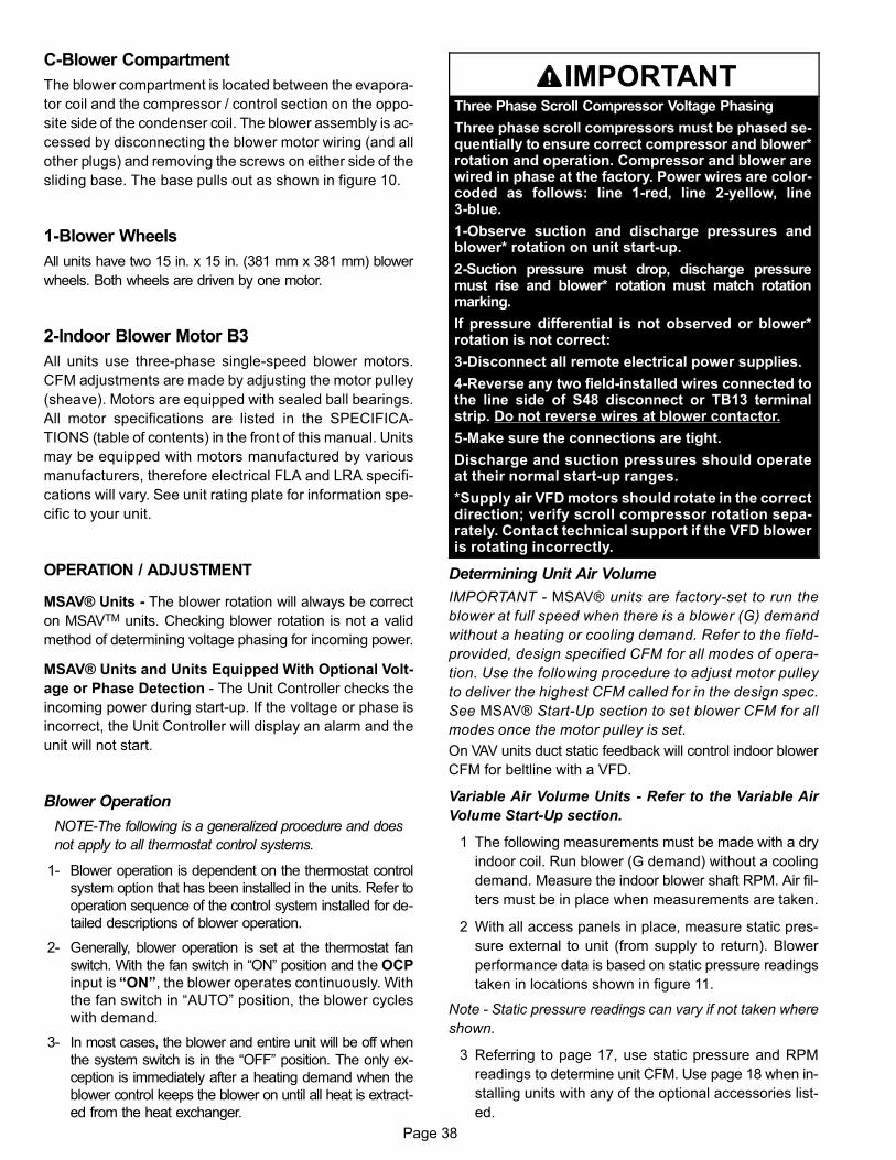
Page 38
C-Blower Compartment
The blower compartment is located between the evapora
tor coil and the compressor / control section on the oppo
site side of the condenser coil. The blower assembly is ac
cessed by disconnecting the blower motor wiring (and all
other plugs) and removing the screws on either side of the
sliding base. The base pulls out as shown in figure 10.
1-Blower Wheels
All units have two 15 in. x 15 in. (381 mm x 381 mm) blower
wheels. Both wheels are driven by one motor.
2-Indoor Blower Motor B3
All units use three‐phase single‐speed blower motors.
CFM adjustments are made by adjusting the motor pulley
(sheave). Motors are equipped with sealed ball bearings.
All motor specifications are listed in the SPECIFICA
TIONS (table of contents) in the front of this manual. Units
may be equipped with motors manufactured by various
manufacturers, therefore electrical FLA and LRA specifi
cations will vary. See unit rating plate for information spe
cific to your unit.
OPERATION / ADJUSTMENT
MSAV® Units - The blower rotation will always be correct
on MSAVTM units. Checking blower rotation is not a valid
method of determining voltage phasing for incoming power.
MSAV® Units and Units Equipped With Optional Volt
age or Phase Detection - The Unit Controller checks the
incoming power during start-up. If the voltage or phase is
incorrect, the Unit Controller will display an alarm and the
unit will not start.
Blower Operation
NOTE-The following is a generalized procedure and does
not apply to all thermostat control systems.
1- Blower operation is dependent on the thermostat control
system option that has been installed in the units. Refer to
operation sequence of the control system installed for de
tailed descriptions of blower operation.
2- Generally, blower operation is set at the thermostat fan
switch. With the fan switch in “ON” position and the OCP
input is “ON”, the blower operates continuously. With
the fan switch in “AUTO” position, the blower cycles
with demand.
3- In most cases, the blower and entire unit will be off when
the system switch is in the “OFF” position. The only ex
ception is immediately after a heating demand when the
blower control keeps the blower on until all heat is extract
ed from the heat exchanger.
IMPORTANTThree Phase Scroll Compressor Voltage Phasing
Three phase scroll compressors must be phased sequentially to ensure correct compressor and blower*rotation and operation. Compressor and blower arewired in phase at the factory. Power wires are color-coded as follows: line 1-red, line 2-yellow, line3-blue.
1-Observe suction and discharge pressures andblower* rotation on unit start-up.
2-Suction pressure must drop, discharge pressuremust rise and blower* rotation must match rotationmarking.
If pressure differential is not observed or blower*rotation is not correct:
3-Disconnect all remote electrical power supplies.
4-Reverse any two field-installed wires connected tothe line side of S48 disconnect or TB13 terminalstrip. Do not reverse wires at blower contactor.
5-Make sure the connections are tight.
Discharge and suction pressures should operateat their normal start‐up ranges.
*Supply air VFD motors should rotate in the correctdirection; verify scroll compressor rotation separately. Contact technical support if the VFD bloweris rotating incorrectly.
Determining Unit Air Volume
IMPORTANT - MSAV® units are factory-set to run the
blower at full speed when there is a blower (G) demand
without a heating or cooling demand. Refer to the field-
provided, design specified CFM for all modes of opera
tion. Use the following procedure to adjust motor pulley
to deliver the highest CFM called for in the design spec.
See MSAV® Start-Up section to set blower CFM for all
modes once the motor pulley is set.
On VAV units duct static feedback will control indoor blower
CFM for beltline with a VFD.
Variable Air Volume Units - Refer to the Variable Air
Volume Start-Up section.
1 The following measurements must be made with a dry
indoor coil. Run blower (G demand) without a cooling
demand. Measure the indoor blower shaft RPM. Air fil
ters must be in place when measurements are taken.
2 With all access panels in place, measure static pres
sure external to unit (from supply to return). Blower
performance data is based on static pressure readings
taken in locations shown in figure 11.
Note - Static pressure readings can vary if not taken where
shown.
3 Referring to page 17, use static pressure and RPM
readings to determine unit CFM. Use page 18 when in
stalling units with any of the optional accessories list
ed.

Page 39
4 The blower RPM can be adjusted at the motor pulley.
Loosen Allen screw and turn adjustable pulley clock
wise to increase CFM. Turn counterclockwise to de
crease CFM. See figure 10. Do not exceed minimum
and maximum number of pulley turns as shown in table
5.
TABLE 5MINIMUM AND MAXIMUM PULLEY ADJUSTMENT
Belt Minimum Turns Open Maximum Turns Open
A Section No minimum 5
B Section 1* 6
*No minimum number of turns open when B belt is used onpulleys 6” O.D. or larger.
FIGURE 10
BLOWER ASSEMBLYBLOWER MAY NEED TO BE
REMOVED TO INSPECT HEATEXCHANGER, REAR BLOWER
BEARINGS, ETC.
TO INCREASE BELT TENSION
1-Loosen four screws securing blower motor to sliding base.
2-Turn adjusting screw to the left, or counterclockwise, to move the motor downward and tighten the belt.
3-Tighten four screws.
TO INCREASE AIR VOLUMELOOSEN ALLEN SCREW & TURN
PULLEY CLOCKWISE
TO DECREASE AIR VOLUMETURN PULLEY COUNTERCLOCKWISE
BLOWER WHEEL
PULLEY
ALLEN SCREW
BLOWER ASSEMBLYSLIDING BASE
BELT TENSIONADJUSTING
SCREW
LOOSEN (4) SCREWS TOADJUST BELT TENSION
BLOWER WHEEL BRACKET
BLOWER MOTOR
REMOVE SCREWS TOSLIDE BLOWER
ASSEMBLY OUT OF UNIT
FIGURE 11
LOCATION OF STATIC PRESSURE READINGS
SUPPLY AIRREADING LOCA
TION
SUPPLYRE
TURN
INSTALLATIONS WITH DUCTWORK
SUPPLY RETURN
INSTALLATIONS WITH CEILING DIFFUSERS
MAINDUCT RUN
FIRST BRANCHOFF OF MAIN RUN
DIFFUSER
ROOFTOP UNIT ROOFTOP UNIT
SUPPLY AIRREADING LOCA
TION
RETURN AIRREADING LOCATION
RETURN AIRREADING LOCA
TION

Page 40
Determining Unit Air Volume
1- The following measurements must be made with a dry in
door coil. Run blower without cooling demand. Air filters
must be in place when measurements are taken.
2- With all access panels in place, measure static
pressure external to unit (from supply to return).
3- Measure the indoor blower wheel RPM.
4- Refer to blower tables in BLOWER DATA (table of con
tents) in the front of this manual. Use static pressure and
RPM readings to determine unit air volume.
5- The RPM can be adjusted at the motor pulley. Loosen
Allen screw and turn adjustable pulley clockwise to in
crease RPM. Turn counterclockwise to decrease RPM.
See figure 10.
Blower Belt Adjustment
Maximum life and wear can be obtained from belts only if
proper pulley alignment and belt tension are maintained.
Tension new belts after a 24-48 hour period of operation.
This will allow belt to stretch and seat into pulley grooves.
Make sure blower and motor pulley are aligned as shown in
figure 12 for standard blowers and figure 13 for units
equipped with an optional belt tensioner.
PULLEY ALIGNMENT - STANDARD BLOWERS
BELTBLOWERPULLEY
MOTORPULLEY
NOT ALIGNED
ALIGNED
FIGURE 12
BELTBLOWERPULLEYMOTOR
PULLEYNOT ALIGNED
ALIGNED
TENSIONER
PULLEY ALIGNMENT - WITH TENSIONER
FIGURE 13
Standard Blowers
1 Loosen four screws securing blower motor to sliding
base. See figure 10.
2 To increase belt tension -
Turn belt tension adjusting screw to the left, or counter
clockwise, to tighten the belt. This increases the dis
tance between the blower motor and the blower hous
ing.
To loosen belt tension -
Turn the adjusting screw to the right, or clockwise to
loosen belt tension.
3 Tighten four screws securing blower motor to sliding
base once adjustments have been made.
Blowers Equipped With Belt Tensioner
1 Loosen the bolt in the center of the tensioner. See fig
ure 14.
2 Place belt over all three pulleys.
3 Using a 15/16” wrench, turn the tensioner nut until
marks align as shown in figure 14.
4 Hold the tensioner with marks aligned and tighten the
bolt to 22 ft.lbs. using the 9/16” wrench.

Page 41
BOLT
PULLEY ALIGNMENT - WITH TENSIONER
NUT
ALIGNTENSIONER
MARKS
ADJUSTABLEPULLEY
FIXEDPULLEY
TENSIONERTENSIONER BOLT AND
ADJUSTMENT NUT
FIGURE 14
Check Belt Tension
Overtensioning belts shortens belt and bearing life. Check
belt tension as follows:
1 Measure span length X. See figure 15.
2 Apply perpendicular force to center of span (X) with
enough pressure to deflect belt 1/64” for every inch of
span length or 1.5mm per 100mm of span length.
Example: Deflection distance of a 40” span would be
40/64” or 5/8”.
Example: Deflection distance of a 400mm span would
be 6mm.
3 Measure belt deflection force. For a used belt, the de
flection force should be 5 lbs. (35kPa) . A new belt de
flection force should be 7 lbs. (48kPa).
A force below these values indicates and underten
sioned belt. A force above these values indicates an
overtensioned belt.
MEASURE BELT TENSION
DEFLECTION 1/64” PER INCH OF SPANOR 1.5mm PER 100mm OF SPAN
FORCE
FIGURE 15
Field-Furnished Blower Drives
For field-furnished blower drives, Refer to blower tables in
BLOWER DATA section to determine BHP and RPM re
quired. Reference table 6 and 7 to determine the manufac
turer's model number.

Page 42
TABLE 6
DriveNo.
H.P.
DRIVE COMPONENTS
RPM ADJUSTABLE SHEAVE FIXED SHEAVE
Min Max Supplier No.OEM
Part No. Supplier No. OEM Part No.
1 2 & 3 Std. 535 725 1VP40x7/8 79J0301 BK95 x 1-7/16 80K1601
2 2 & 3 Std. 710 965 1VP40x7/8 79J0301 BK72 x 1‐7/16 100244-13
3 3 High & 5 685 865 1VP50x1-1/8 P-8-1977 BK100 x 1‐7/16 39L1301
4 3 High & 5 850 1045 1VP65x1-1/8 100239-03 BK110H 100788-06
5 5 945 1185 1VP60x1-1/8 41C1301 BK90H x 1-7/16 100788-04
6 7.5 850 1045 1VP65x1-3/8 78M7101 BK110H 100788-06
7 7.5 & 10 945 1185 1VP60x1-3/8 78L5501 BK90H x 1-7/16 100788-04
8 7.5 1045 1285 1VP65x1-3/8 78M7101 BK90H x 1-7/16 100788-04
10 10 1045 1285 1VP65x1-3/8 78M7101 1B5V86 78M8301
11 10 1135 1365 1VP65x1-3/8 78M7101 1B5V80 100240-05
TABLE 7
DriveNo.
H.P.
DRIVE COMPONENTS
RPM BELTS (STD.)BELTS (WITHTENSIONER)
SPLIT BUSHING
Min MaxSupplier
No.OEM
Part No.Supplier
No.OEM
Part No. Supplier No.OEM
Part No.
1 2 & 3 Std. 535 725 BX59 59A5001 BX60 100245-10 N/A N/A
2 2 & 3 Std. 710 965 BX55 63K0501 BX56 100245-11 N/A N/A
3 3 High & 5 685 865 BX61 93J9801 BX62 57A7701 N/A N/A
4 3 High & 5 850 1045 BX66 97J5901 BX67 100245-09 H-1-7/16 49M6201
5 5 945 1185 BX61 93J9801 BX62 57A7701 H-1-7/16 49M6201
6 7.5 850 1045 BX66 97J5901 BX67 100245-09 H-1-7/16 49M6201
7 7.5 & 10 945 1185 BX63 97J5501 BX64 97J5801 H-1-7/16 49M6201
8 7.5 1045 1285 BX64 97J5801 BX65 100245-08 H-1-7/16 49M6201
10 10 1045 1285 5VX670 100245-21 5VX680 100245-35 B-1-7/16 100246-01
11 10 1135 1365 5VX660 100245-20 5VX670 100245-21 B-1-7/16 100246-01

Page 43
D-Optional Electric Heat Components
See ELECTRICAL / ELECTRIC HEAT DATA and ELEC
TRIC HEAT CAPACITIES (table of contents) for LCH to
EHA match-ups and electrical ratings.
EHA parts arrangement is shown in figures 17 and 18. All
electric heat sections consist of electric heating elements
exposed directly to the air stream. Two electric heat sec
tions (first section and second section) are used in all 15kW
through 90kW heaters. See figure 16. Multiple‐stage ele
ments are sequenced on and off in response to thermostat
demand.
FIGURE 16
HEAT SECTION PLACEMENT
FIRST ELECTRICHEAT SECTION
(LEFT SIDE)
SECOND ELECTRICHEAT SECTION(RIGHT SIDE)
COMPRESSORCOMPARTMENT
1-Main Control Box Components A55, K9
The main control box (see figure 1) houses the A55
Unit Controller and the K9 electric heat relay. For a de
scription of the components see section I‐A.
2-Contactors K15, K16, K17 and K18
Contactors K15, K16, K17 and K18 are all three‐pole
double‐break contactors located on the electric heat
vestibule. K15 and K16 are located on the first electric
heat section, while K17 and K18 are located on the
second electric heat section. However, in the 15 and
30kW heaters, the first section houses all contactors
and fuses. All contactors are equipped with a 24VAC
coil. The coils in the K15, K16, K17 and K18 contactors
are energized by the main panel A55. Contactors K15
and K17 energize the first stage heating elements,
while K16 and K18 energize the second stage heating
elements.
3-High Temperature Limits S15 and S107 (Primary)
S15 and S107 are SPST N.C. auto‐reset thermostats
located on the back panel of the electric heat section
below the heating elements. S15 is the high tempera
ture limit for the first electric heat section, while S107 is
the high temperature limit for the second electric heat
section. Both thermostats are identical and are wired to
the A55 Unit Controller. When either S15 or S107
opens, indicating a problem in the system, contactor
K15 is de‐energized. When K15 is de‐energized, first
stage and all subsequent stages of heat are de‐ener
gized. The thermostats used on EHA360‐45‐1 Y/G/J
are factory set to open at 200�F + 5�F (93.3�C +
2.8�C) on a temperature rise and automatically reset
at 160�F + 6�F (71.1�C + 3.3�C) on a temperature fall.
All other electric heat section thermostats are factory
set to open at 170�F + 5�F (76.7�C + 2.8�C) on a tem
perature rise and automatically reset at 130�F + 6�F
(54.4�C + 3.3�C) on a temperature fall. The ther
mostats are not adjustable.
4-Terminal Strip TB3
Electric heat line voltage connections are made to ter
minal strip TB3 (or a fuse block on some models) locat
ed in the upper left corner of the electric heat vestibule.
5-Heating Elements HE1 through HE14
Heating elements are composed of helix wound bare
nichrome wire exposed directly to the air stream.
Three elements are connected in a three‐phase ar
rangement. The elements in 208/230V units are con
nected in a “Delta” arrangement. Elements in 460 and
575V units are connected in “Wye” arrangement.
Each stage is energized independently by the corre
sponding contactors located on the electric heat
vestibule panel. Once energized, heat transfer is in
stantaneous. High temperature protection is provided
by primary and redundant high temperature limits and
overcurrent protection is provided by fuses.
6-Fuse F3
Fuse F3 are housed in a fuse block which holds three
fuses. Each F3 fuse is connected in series with each
leg of electric heat. Figures 17 and 18 and table 8
shows the fuses used with each electric heat section.
For simplicity, the service manual labels the fuses F3
- 1 through F3 - 8.
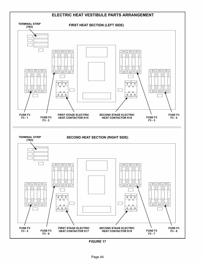
Page 44
FIGURE 17
ELECTRIC HEAT VESTIBULE PARTS ARRANGEMENT
TERMINAL STRIP(TB3)
FIRST STAGE ELECTRICHEAT CONTACTOR K15
SECOND STAGE ELECTRICHEAT CONTACTOR K16
FIRST HEAT SECTION (LEFT SIDE)
SECOND HEAT SECTION (RIGHT SIDE)
FUSE F3F3 ‐ 1 FUSE F3
F3 ‐ 2FUSE F3
F3 ‐ 3
FUSE F3F3 ‐ 4
TERMINAL STRIP(TB3)
FIRST STAGE ELECTRICHEAT CONTACTOR K17
SECOND STAGE ELECTRICHEAT CONTACTOR K18
FUSE F3F3 ‐ 5 FUSE F3
F3 ‐ 6FUSE F3
F3 ‐ 7
FUSE F3F3 ‐ 8
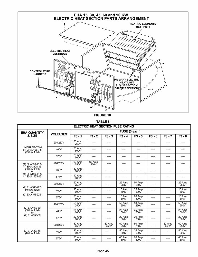
Page 45
FIGURE 18
EHA 15, 30, 45, 60 and 90 KW ELECTRIC HEAT SECTION PARTS ARRANGEMENT
PRIMARY ELECTRICHEAT LIMIT
S15(1ST SECTION)S107(2nd SECTION)
HEATING ELEMENTSHE1 - HE14
CONTROL WIREHARNESS
ELECTRIC HEATVESTIBULE
TABLE 8
ELECTRIC HEAT SECTION FUSE RATING
EHA QUANTITY& SIZE VOLTAGES
FUSE (3 each)
F3 - 1 F3 - 2 F3 - 3 F3 - 4 F3 - 5 F3 - 6 F3 - 7 F3 - 8
(1) EHA240-7.5 &(1) EHA240S-7.5
(15 kW Total)
208/230V50 Amp250V ----- ----- ----- ----- ----- ----- -----
460V25 Amp600V ----- ----- ----- ----- ----- ----- -----
575V20 Amp600V ----- ----- ----- ----- ----- ----- -----
(1) EHA360-15 &(1) EHA360S-15
(30 kW Total)or
(1) EHA156-15 &(1) EHA156S-15
208/230V60 Amp250V
60 Amp250V ----- ----- ----- ----- ----- -----
460V50 Amp600V ----- ----- ----- ----- ----- ----- -----
575V40 Amp600V ----- ----- ----- ----- ----- ----- -----
(2) EHA360-22.5(45 kW Total)
or(2) EHA156-22.5
208/230V50 Amp250V ----- -----
25 Amp250V
50 Amp250V ----- -----
25 Amp250V
460V25 Amp600V ----- -----
15 Amp600V
25 Amp600V ----- -----
15 Amp600V
575V20 Amp600V ----- -----
10 Amp600V
20 Amp600V ----- -----
10 Amp600V
(2) EHA150-30(60 kW Total)
or(2) EHA156-30
208/230V50 Amp250V ----- -----
50 Amp250V
50 Amp250V ----- -----
50 Amp250V
460V25 Amp600V ----- -----
25 Amp600V
25 Amp600V ----- -----
25 Amp600V
575V20 Amp600V ----- -----
20 Amp600V
20 Amp600V ----- -----
20 Amp600V
(2) EHA360-45(90 kW Total)
208/230V50 Amp250V -----
60 Amp250V
60 Amp250V
50 Amp250V -----
60 Amp250V
60 Amp250V
460V25 Amp600V ----- -----
50 Amp600V
25 Amp600V ----- -----
50 Amp600V
575V20 Amp600V ----- -----
40 Amp600V
20 Amp600V ----- -----
40 Amp600V

Page 46
II-PLACEMENT AND INSTALLATION Make sure the unit is installed in accordance with the in
stallation instructions and all applicable codes. See ac
cessories section for conditions requiring use of the op
tional roof mounting frame (LARMF18/36 or
LARMFH18/24).
III-CHARGING
WARNINGRefrigerant can be harmful if it is inhaled. Refrigerantmust be used and recovered responsibly.
Failure to follow this warning may result in personal injury or death.
IMPORTANTUnits equipped with Hot Gas Re-Heat system MUST be charged
in standard cooling mode.
A-Aluminum Coils
WARNING-Do not exceed nameplate charge under any
condition.
This unit is factory charged and should require no further
adjustment. If the system requires additional refrigerant,
reclaim the charge, evacuate the system, and add required
nameplate charge.
NOTE - System charging is not recommended below 60�F
(15�C). In temperatures below 60�F (15�C), the charge
must be weighed into the system.
If weighing facilities are not available, or to check the
charge, use the following procedure:
IMPORTANT - Charge unit in standard cooling mode.
1 Make sure outdoor coil is clean. Attach gauge manifolds
and operate unit at full CFM in cooling mode with econo
mizer disabled until system stabilizes (approximately five
minutes). Make sure all outdoor air dampers are closed.
2 Check each system separately with all stages operat
ing. Compare the normal operating pressures (see ta
bles 9 - 21) to the pressures obtained from the gauges.
Check unit components if there are significant differ
ences.
3 Measure the outdoor ambient temperature and the suc
tion pressure. Refer to the appropriate circuit charging
curves to determine a target liquid temperature.
Note - Pressures are listed for sea level applications.
4 Use the same thermometer to accurately measure the
liquid temperature (in the outdoor section).
� If measured liquid temperature is higher than the
target liquid temperature, add refrigerant to the
system.
� If measured liquid temperature is lower than the
target liquid temperature, recover some refriger
ant from the system.
5 Add or remove charge in increments. Allow the system to
stabilize each time refrigerant is added or removed.
6 Continue the process until measured liquid tempera
ture agrees with the target liquid temperature. Do not
go below the target liquid temperature when adjusting
charge. Note that suction pressure can change as
charge is adjusted.
7 Example LGH/LCH180H Circuit 1: At 95°F outdoor
ambient and a measured suction pressure of 130psig,
the target liquid temperature is 96.5°F. For a measured
liquid temperature of 106°F, add charge in increments
until measured liquid temperature agrees with the tar
get liquid temperature.
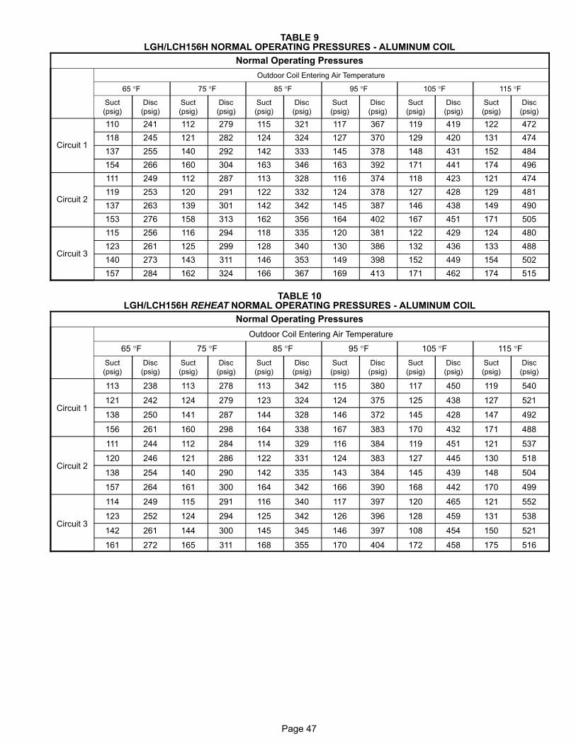
Page 47
TABLE 9LGH/LCH156H NORMAL OPERATING PRESSURES - ALUMINUM COIL
Normal Operating Pressures
Outdoor Coil Entering Air Temperature
65 °F 75 °F 85 °F 95 °F 105 °F 115 °F
Suct
(psig)
Disc
(psig)
Suct
(psig)
Disc
(psig)
Suct
(psig)
Disc
(psig)
Suct
(psig)
Disc
(psig)
Suct
(psig)
Disc
(psig)
Suct
(psig)
Disc
(psig)
Circuit 1
110 241 112 279 115 321 117 367 119 419 122 472
118 245 121 282 124 324 127 370 129 420 131 474
137 255 140 292 142 333 145 378 148 431 152 484
154 266 160 304 163 346 163 392 171 441 174 496
Circuit 2
111 249 112 287 113 328 116 374 118 423 121 474
119 253 120 291 122 332 124 378 127 428 129 481
137 263 139 301 142 342 145 387 146 438 149 490
153 276 158 313 162 356 164 402 167 451 171 505
Circuit 3
115 256 116 294 118 335 120 381 122 429 124 480
123 261 125 299 128 340 130 386 132 436 133 488
140 273 143 311 146 353 149 398 152 449 154 502
157 284 162 324 166 367 169 413 171 462 174 515
TABLE 10LGH/LCH156H REHEAT NORMAL OPERATING PRESSURES - ALUMINUM COIL
Normal Operating Pressures
Outdoor Coil Entering Air Temperature
65 °F 75 °F 85 °F 95 °F 105 °F 115 °F
Suct
(psig)
Disc
(psig)
Suct
(psig)
Disc
(psig)
Suct
(psig)
Disc
(psig)
Suct
(psig)
Disc
(psig)
Suct
(psig)
Disc
(psig)
Suct
(psig)
Disc
(psig)
Circuit 1
113 238 113 278 113 342 115 380 117 450 119 540
121 242 124 279 123 324 124 375 125 438 127 521
138 250 141 287 144 328 146 372 145 428 147 492
156 261 160 298 164 338 167 383 170 432 171 488
Circuit 2
111 244 112 284 114 329 116 384 119 451 121 537
120 246 121 286 122 331 124 383 127 445 130 518
138 254 140 290 142 335 143 384 145 439 148 504
157 264 161 300 164 342 166 390 168 442 170 499
Circuit 3
114 249 115 291 116 340 117 397 120 465 121 552
123 252 124 294 125 342 126 396 128 459 131 538
142 261 144 300 145 345 146 397 108 454 150 521
161 272 165 311 168 355 170 404 172 458 175 516

Page 48
TABLE 11LGH/LCH156H VAV NORMAL OPERATING PRESSURES - ALUMINUM COIL
Normal Operating Pressures
Outdoor Coil Entering Air Temperature
65 °F 75 °F 85 °F 95 °F 105 °F 115 °F
Suct
(psig)
Disc
(psig)
Suct
(psig)
Disc
(psig)
Suct
(psig)
Disc
(psig)
Suct
(psig)
Disc
(psig)
Suct
(psig)
Disc
(psig)
Suct
(psig)
Disc
(psig)
Circuit 1
101 232 103 271 104 315 106 372 109 434 111 511
109 234 111 275 113 317 114 367 118 425 119 500
128 239 130 277 132 319 134 367 136 420 139 481
141 245 147 284 153 326 156 373 159 424 158 479
Circuit 2
108 235 110 273 111 320 113 370 115 441 117 531
117 238 119 276 121 319 123 367 125 426 126 506
134 246 138 283 140 325 142 372 144 426 146 489
149 253 156 292 161 334 164 380 167 433 166 490
Circuit 3
119 252 121 291 123 336 125 386 126 445 129 507
129 256 131 295 133 339 134 387 137 445 139 510
146 264 150 303 153 346 156 394 158 446 161 505
161 274 167 313 172 357 176 404 180 456 181 513
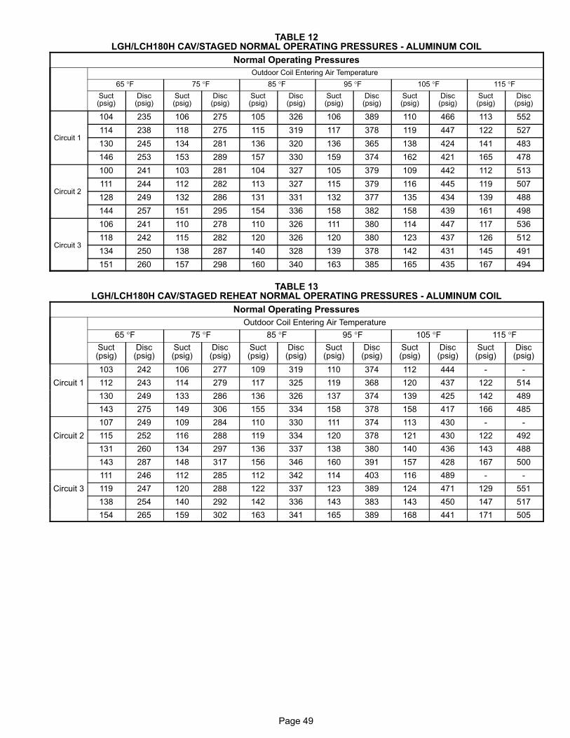
Page 49
TABLE 12LGH/LCH180H CAV/STAGED NORMAL OPERATING PRESSURES - ALUMINUM COIL
Normal Operating Pressures
Outdoor Coil Entering Air Temperature
65 °F 75 °F 85 °F 95 °F 105 °F 115 °FSuct(psig)
Disc(psig)
Suct(psig)
Disc(psig)
Suct(psig)
Disc(psig)
Suct(psig)
Disc(psig)
Suct(psig)
Disc(psig)
Suct(psig)
Disc(psig)
Circuit 1
104 235 106 275 105 326 106 389 110 466 113 552
114 238 118 275 115 319 117 378 119 447 122 527
130 245 134 281 136 320 136 365 138 424 141 483
146 253 153 289 157 330 159 374 162 421 165 478
Circuit 2
100 241 103 281 104 327 105 379 109 442 112 513
111 244 112 282 113 327 115 379 116 445 119 507
128 249 132 286 131 331 132 377 135 434 139 488
144 257 151 295 154 336 158 382 158 439 161 498
Circuit 3
106 241 110 278 110 326 111 380 114 447 117 536
118 242 115 282 120 326 120 380 123 437 126 512
134 250 138 287 140 328 139 378 142 431 145 491
151 260 157 298 160 340 163 385 165 435 167 494
TABLE 13LGH/LCH180H CAV/STAGED REHEAT NORMAL OPERATING PRESSURES - ALUMINUM COIL
Normal Operating Pressures
Outdoor Coil Entering Air Temperature
65 °F 75 °F 85 °F 95 °F 105 °F 115 °FSuct(psig)
Disc(psig)
Suct(psig)
Disc(psig)
Suct(psig)
Disc(psig)
Suct(psig)
Disc(psig)
Suct(psig)
Disc(psig)
Suct(psig)
Disc(psig)
103 242 106 277 109 319 110 374 112 444 - -
Circuit 1 112 243 114 279 117 325 119 368 120 437 122 514
130 249 133 286 136 326 137 374 139 425 142 489
143 275 149 306 155 334 158 378 158 417 166 485
107 249 109 284 110 330 111 374 113 430 - -
Circuit 2 115 252 116 288 119 334 120 378 121 430 122 492
131 260 134 297 136 337 138 380 140 436 143 488
143 287 148 317 156 346 160 391 157 428 167 500
111 246 112 285 112 342 114 403 116 489 - -
Circuit 3 119 247 120 288 122 337 123 389 124 471 129 551
138 254 140 292 142 336 143 383 143 450 147 517
154 265 159 302 163 341 165 389 168 441 171 505

Page 50
TABLE 14LGH/LCH180H VAV NORMAL OPERATING PRESSURES - ALUMINUM COIL
Normal Operating Pressures
Outdoor Coil Entering Air Temperature
65 °F 75 °F 85 °F 95 °F 105 °F 115 °F
Suct
(psig)
Disc
(psig)
Suct
(psig)
Disc
(psig)
Suct
(psig)
Disc
(psig)
Suct
(psig)
Disc
(psig)
Suct
(psig)
Disc
(psig)
Suct
(psig)
Disc
(psig)
Circuit 1 102 234 104 273 106 311 108 358 111 411 114 471
110 235 112 276 114 314 116 360 119 410 122 470
123 242 127 283 130 320 132 367 135 418 138 476
135 251 141 290 145 333 149 380 152 431 155 486
Circuit 2 103 236 105 273 107 315 109 363 111 417 113 472
110 239 113 276 115 317 117 362 120 415 122 475
123 246 127 283 132 324 135 370 138 421 141 477
134 253 141 290 146 332 152 377 156 429 160 481
Circuit 3 115 243 117 280 119 321 121 369 124 419 126 477
123 246 126 282 128 324 130 368 133 419 135 477
136 256 141 293 145 334 152 384 152 430 155 485
150 272 155 304 161 345 166 391 171 439 175 490
TABLE 15LGH/LCH210H NORMAL OPERATING PRESSURES - ALUMINUM COIL
Normal Operating Pressures
Outdoor Coil Entering Air Temperature
65 °F 75 °F 85 °F 95 °F 105 °F 115 °F
Suct
(psig)
Disc
(psig)
Suct
(psig)
Disc
(psig)
Suct
(psig)
Disc
(psig)
Suct
(psig)
Disc
(psig)
Suct
(psig)
Disc
(psig)
Suct
(psig)
Disc
(psig)
Circuit 1
110 228 113 262 114 302 116 349 118 402 119 466
119 231 121 266 123 305 125 352 127 405 128 466
136 238 139 271 141 312 143 358 146 409 149 464
152 246 157 277 161 319 165 363 169 414 171 472
Circuit 2
112 232 111 267 113 312 115 358 116 414 119 479
121 235 123 272 125 311 127 357 126 415 129 476
137 242 141 278 144 317 146 365 149 415 151 471
153 253 159 289 164 333 168 374 171 425 174 478
Circuit 3
105 241 106 284 108 327 110 375 112 429 115 489
112 244 115 282 118 323 121 369 121 428 123 487
130 251 132 289 135 332 138 378 141 428 145 484
146 261 151 297 156 339 159 386 163 437 165 495

Page 51
TABLE 16LGH/LCH210H REHEAT NORMAL OPERATING PRESSURES - ALUMINUM COIL
Normal Operating Pressures
Outdoor Coil Entering Air Temperature
65 °F 75 °F 85 °F 95 °F 105 °F 115 °F
Suct
(psig)
Disc
(psig)
Suct
(psig)
Disc
(psig)
Suct
(psig)
Disc
(psig)
Suct
(psig)
Disc
(psig)
Suct
(psig)
Disc
(psig)
Suct
(psig)
Disc
(psig)
Circuit 1
109 234 111 270 114 311 115 357 118 410 121 472
119 237 120 274 122 314 125 360 127 412 130 472
137 246 140 281 143 321 146 365 146 417 150 473
152 260 158 292 162 330 166 373 170 421 173 476
Circuit 2
113 240 115 276 114 320 115 369 117 420 122 478
122 244 123 281 125 321 125 369 127 423 130 481
139 254 143 291 146 330 148 374 150 424 152 480
154 267 160 302 165 341 169 384 172 431 176 486
Circuit 3
111 239 113 277 116 319 115 371 117 427 121 488
119 243 281 281 123 326 125 374 127 430 130 489
135 252 139 291 143 332 145 379 148 432 150 490
149 265 155 303 160 344 164 390 168 438 173 496
TABLE 17LGH/LCH240H CAV/STAGED NORMAL OPERATING PRESSURES - ALUMINUM COIL
Normal Operating Pressures
Outdoor Coil Entering Air Temperature
65 °F 75 °F 85 °F 95 °F 105 °F 115 °FSuct(psig)
Disc(psig)
Suct(psig)
Disc(psig)
Suct(psig)
Disc(psig)
Suct(psig)
Disc(psig)
Suct(psig)
Disc(psig)
Suct(psig)
Disc(psig)
Circuit 1
107 249 109 286 111 331 113 391 116 450 118 513
115 251 118 285 120 332 122 383 125 443 128 513
134 255 136 291 139 334 141 383 143 441 146 506
156 269 160 305 164 352 163 393 166 451 168 508
Circuit 2
105 236 106 277 109 320 112 373 114 445 116 538
114 239 116 275 117 323 119 372 122 438 125 530
131 245 134 279 136 322 138 372 140 427 144 489
153 257 157 291 161 337 161 377 164 433 167 486
Circuit 3
110 247 112 286 114 330 115 386 117 444 119 507
119 251 121 289 122 334 123 384 126 442 128 512
136 259 139 298 141 341 144 389 145 445 147 506
157 276 162 314 166 358 166 399 168 457 170 511
Circuit 4
104 240 106 276 108 319 110 372 111 435 115 492
113 244 114 280 117 320 117 371 120 432 123 497
128 251 131 289 133 331 136 376 139 430 142 486
149 264 154 301 157 345 157 387 161 442 165 493

Page 52
TABLE 18LGH/LCH240H CAV/STAGED REHEAT NORMAL OPERATING PRESSURES - ALUMINUM COIL
Normal Operating Pressures
Outdoor Coil Entering Air Temperature
65 °F 75 °F 85 °F 95 °F 105 °F 115 °FSuct(psig)
Disc(psig)
Suct(psig)
Disc(psig)
Suct(psig)
Disc(psig)
Suct(psig)
Disc(psig)
Suct(psig)
Disc(psig)
Suct(psig)
Disc(psig)
111 252 112 288 112 334 114 386 116 441 118 502
Circuit 1 119 256 121 294 122 337 123 387 125 440 127 499
136 266 140 303 142 345 145 391 147 446 148 499
140 268 155 314 160 356 164 402 168 451 172 505
108 246 109 282 110 326 112 379 114 438 116 512
Circuit 2 116 248 118 286 119 330 120 379 122 426 125 501
133 257 137 294 138 335 140 382 142 440 145 494
138 259 152 303 158 345 161 390 165 437 168 492
115 248 117 285 118 327 121 375 124 426 127 479
Circuit 3 121 252 125 290 128 332 129 378 131 429 135 484
135 260 140 299 144 341 148 388 152 442 153 493
141 262 154 308 160 353 164 399 169 450 173 504
112 243 114 278 115 319 118 365 116 425 120 479
Circuit 4 118 246 122 283 125 324 126 369 127 418 129 479
133 254 137 291 141 332 145 377 148 430 150 481
138 257 151 301 157 344 161 389 166 437 170 491
TABLE 19LGH/LCH240H VAV NORMAL OPERATING PRESSURES - ALUMINUM COIL
Normal Operating Pressures
Outdoor Coil Entering Air Temperature
65 °F 75 °F 85 °F 95 °F 105 °F 115 °F
Suct
(psig)
Disc
(psig)
Suct
(psig)
Disc
(psig)
Suct
(psig)
Disc
(psig)
Suct
(psig)
Disc
(psig)
Suct
(psig)
Disc
(psig)
Suct
(psig)
Disc
(psig)
Circuit 1
98 238 101 276 102 318 105 367 108 413 110 467
107 240 109 278 111 321 113 368 116 418 119 474
124 248 127 284 129 325 132 372 134 422 137 478
143 255 145 293 148 333 152 380 154 428 157 482
Circuit 2
101 230 103 267 105 309 108 360 110 407 113 462
109 232 111 268 113 311 116 358 118 411 121 467
125 239 129 274 132 315 135 362 137 413 140 471
141 245 145 283 150 323 154 371 158 419 161 474
Circuit 3
113 249 115 287 117 329 119 381 121 432 123 488
122 252 124 290 126 333 127 381 129 434 131 492
139 263 142 299 145 341 147 388 149 441 152 498
159 275 159 313 164 353 167 402 169 451 172 508
Circuit 4
117 242 119 281 120 324 122 377 124 428 127 486
125 246 127 285 129 329 131 377 133 430 135 490
139 256 145 293 148 335 151 389 153 436 156 495
158 268 161 308 166 348 171 396 174 446 177 504

Page 53
TABLE 20LGH/LCH300S NORMAL OPERATING PRESSURES - ALUMINUM COIL
Normal Operating Pressures
Outdoor Coil Entering Air Temperature
65 °F 75 °F 85 °F 95 °F 105 °F 115 °F
Suct(psig)
Disc(psig)
Suct(psig)
Disc(psig)
Suct(psig)
Disc(psig)
Suct(psig)
Disc(psig)
Suct(psig)
Disc(psig)
Suct(psig)
Disc(psig)
Circuit 1
105 248 109 283 109 330 110 381 112 432 114 486
114 250 117 291 117 338 119 384 121 432 123 487
127 253 134 300 137 343 140 388 141 444 144 501
142 265 149 308 154 349 159 399 163 449 167 503
Circuit 2
103 236 105 272 107 318 108 373 109 428 111 484
112 238 114 278 116 325 116 374 118 425 120 482
127 246 131 285 135 327 137 377 140 433 142 491
141 254 146 294 150 332 156 385 160 437 164 495
Circuit 3
104 258 105 302 107 345 109 399 111 456 114 519
112 263 114 308 115 354 117 403 120 463 123 524
131 297 133 320 136 367 138 410 140 465 142 526
147 313 147 334 152 381 156 423 160 476 165 537
Circuit 4
100 246 103 289 104 329 105 381 107 437 110 500
109 253 110 293 112 337 114 383 116 443 119 505
126 281 127 303 131 349 133 391 136 443 139 499
141 296 143 321 149 370 152 410 157 462 161 521
TABLE 21LGH/LCH300S REHEAT NORMAL OPERATING PRESSURES - ALUMINUM COIL
Normal Operating Pressures
Outdoor Coil Entering Air Temperature
65 °F 75 °F 85 °F 95 °F 105 °F 115 °FSuct(psig)
Disc(psig)
Suct(psig)
Disc(psig)
Suct(psig)
Disc(psig)
Suct(psig)
Disc(psig)
Suct(psig)
Disc(psig)
Suct(psig)
Disc(psig)
Circuit 1
108 259 110 299 112 353 113 396 114 452 117 510
118 263 119 303 120 348 123 396 125 450 128 510
133 275 137 314 139 357 142 407 144 460 148 516
149 288 154 326 159 370 162 416 166 468 171 527
Circuit 2
106 253 107 293 109 348 111 389 113 445 115 509
116 257 118 296 119 340 120 391 122 445 125 506
133 267 136 307 139 349 142 398 142 452 145 512
148 280 153 318 158 360 161 407 164 460 168 521
Circuit 3
110 258 109 304 110 363 111 405 113 463 116 535
119 263 122 304 123 350 122 405 124 463 126 526
135 274 139 316 142 360 145 410 148 463 151 520
149 288 155 329 159 375 163 422 168 475 172 536
Circuit 4
105 251 107 290 107 347 109 390 110 449 113 511
114 256 117 294 119 338 119 388 121 446 123 509
128 268 133 308 136 349 139 397 142 449 144 510
141 282 147 320 152 363 156 408 160 462 165 521

Page 54
70
80
90
100
110
120
110 120 130 140 150 160 170
Suction Pressure (psig)
Outdoor Temperature (°F)
115°
105°
95°
85°
75°
65°
180100
LGH/LCH156 CAV/STAGED CHARGING CURVE CIRCUIT 1 - 580551-03
60
70
80
90
100
110
120
110 120 130 140 150 160 170
Suction Pressure (psig)
Outdoor Temperature (°F)
115°
105°
95°
85°
75°
65°
130
100
LGH/LCH156 CAV/STAGED CHARGING CURVE CIRCUIT 2 - 580551-03

Page 55
70
80
90
100
110
120
110 120 130 140 150 160 170
Suction Pressure (psig)
Outdoor Temperature (°F)
115°
105°
95°
85°
75°
65°
180
130
140LGH/LCH156 CAV/STAGED CHARGING CURVE CIRCUIT 3 - 580551-03
70
80
90
100
110
120
110 120 130 140 150 160 170
Suction Pressure (psig)
Outdoor Temperature (°F)
115°
105°
95°
85°
75°
65°
180100
LGH/LCH156 CAV/STAGED REHEAT CHARGING CURVES CIRCUIT 1 - 580907-02
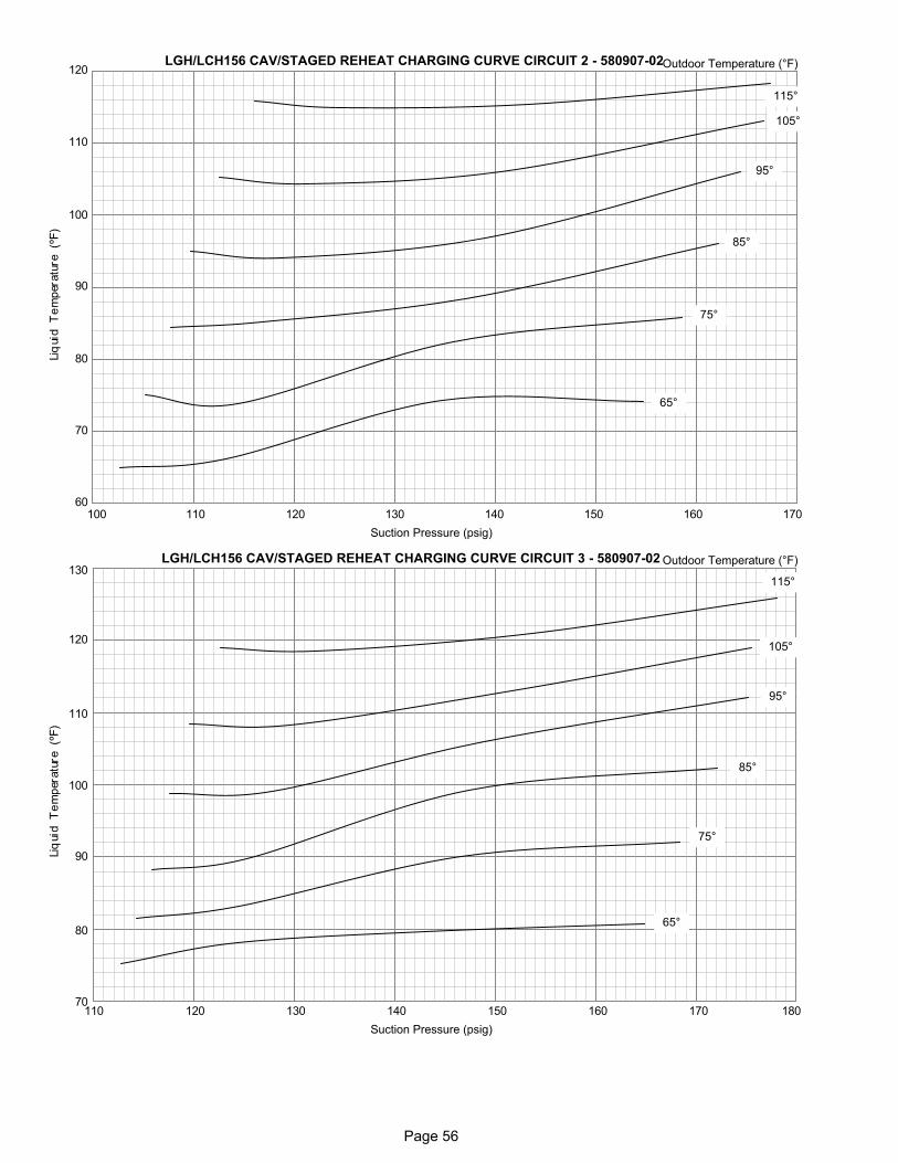
Page 56
70
80
90
100
110
120
110 120 130 140 150 160 170
Suction Pressure (psig)
Outdoor Temperature (°F)
115°
105°
95°
85°
75°
65°
60100
LGH/LCH156 CAV/STAGED REHEAT CHARGING CURVE CIRCUIT 2 - 580907-02
70
80
90
100
110
120
110 120 130 140 150 160 170
Suction Pressure (psig)
Outdoor Temperature (°F)
115°
105°
95°
85°
75°
65°
180
130LGH/LCH156 CAV/STAGED REHEAT CHARGING CURVE CIRCUIT 3 - 580907-02

Page 57
70
80
90
100
110
120
110 120 130 140 150 160
LGH/LCH156 VAV CHARGING CURVE CIRCUIT 1 - 580950-01
Suction Pressure (psig)
Outdoor Temperature (°F)
115°
105°
95°
85°
75°
65°
60100
70
80
90
100
110
120
110 120 130 140 150 160 170
LGH/LCH156 VAV CHARGING CURVE CIRCUIT 2 - 580950-01
Suction Pressure (psig)
Outdoor Temperature (°F)
115°
105°
95°
85°
75°
65°
100

Page 58
70
80
90
100
110
120
115 125 135 145 155 165 175
LGH/LCH156 VAV CHARGING CURVE CIRCUIT 3 - 580950-01
Suction Pressure (psig)
Outdoor Temperature (°F)
115°
105°
95°
85°
75°
65°
185
130

Page 59
60
70
80
90
100
110
120
100 105 110 115 120 125 130 135 140 145 150 155 160 165 170
Suction Pressure (psig)
Outdoor Temperature (°F)
115°
105°
95°
85°
75°
65°
LGH/LCH180 CAV/STAGED CHARGING CURVES CIRCUIT 1
60
70
80
90
100
110
120
100 105 110 115 120 125 130 135 140 145 150 155 160 165 170
Suction Pressure (psig)
Outdoor Temperature (°F)
115°
105°
95°
85°
75°
65°
LGH/LCH180 CAV/STAGED CHARGING CURVES CIRCUIT 2

Page 60
60
70
80
90
100
110
120
100 105 110 115 120 125 130 135 140 145 150 155 160 165 170
115°
105°
95°
85°
75°
65°
Suction Pressure (psig)
Outdoor Temperature (°F)LGH/LCH180 CAV/STAGED CHARGING CURVES CIRCUIT 3

Page 61
70
80
90
100
110
120
110 120 130 140 150 160 170
Suction Pressure (psig)
Outdoor Temperature (°F)
115°
105°
95°
85°
75°
65°
130
60100
LGH/LCH180 CAV/STAGED REHEAT CHARGING CURVES CIRCUIT 1
70
80
90
100
110
120
110 120 130 140 150 160 170
Suction Pressure (psig)
Outdoor Temperature (°F)
115°
105°
95°
85°
75°
65°
130
60100
LGH/LCH180 CAV/STAGED REHEAT CHARGING CURVES CIRCUIT 2

Page 62
70
80
90
100
110
120
110 120 130 140 150 160 170
Suction Pressure (psig)
Outdoor Temperature (°F)
115°
105°
95°
85°
75°
65°
130
60180
LGH/LCH180 CAV/STAGED REHEAT CHARGING CURVES CIRCUIT 3
70
80
90
100
110
120
110 120 130 140 150
Suction Pressure (psig)
Outdoor Temperature (°F)
115°
105°
95°
85°
75°
65°
60
LGH/LCH180 VAV CHARGING CURVES CIRCUIT 1
100

Page 63
70
80
90
100
110
120
110 120 130 140 150 160
Suction Pressure (psig)
Outdoor Temperature (°F)
115°
105°
95°
85°
75°
65°
130LGH/LCH180 VAV CHARGING CURVES CIRCUIT 2
100
70
80
90
100
110
120
110 120 130 140 150 160 170
Suction Pressure (psig)
Outdoor Temperature (°F)
115°
105°
95°
85°
75°
65°
130
60180
LGH/LCH180 VAV CHARGING CURVES CIRCUIT 3

Page 64
60
70
80
90
100
110
120
105 110 115 120 125 130 135 140 145 150 155 160 165 170
LGH/LCH210 CHARGING CURVE CIRCUIT 1
Suction Pressure (psig)
Outdoor Temperature (°F)
115°
105°
95°
85°
75°
65°
175
130
60
70
80
90
100
110
120
110 115 120 125 130 135 140 145 150 155 160 165 170
LGH/LCH210 CHARGING CURVE CIRCUIT 2
Suction Pressure (psig)
Outdoor Temperature (°F)
115°
105°
95°
85°
75°
65°
175 180
130

Page 65
60
70
80
90
100
110
120
100 105 110 115 120 125 130 135 140 145 150 155 160 165 170
LGH/LCH210 CHARGING CURVE CIRCUIT 3
Suction Pressure (psig)
Outdoor Temperature (°F)
115°
105°
95°
85°
75°
65°
130
70
80
90
100
110
120
110 120 130 140 150 160 170
Suction Pressure (psig)
Outdoor Temperature (°F)
115°
105°
95°
85°
75°
65°
130LGH/LCH210 REHEAT CHARGING CURVES CIRCUIT 1
60100 180

Page 66
70
80
90
100
110
120
110 120 130 140 150 160 170
Suction Pressure (psig)
Outdoor Temperature (°F)
115°
105°
95°
85°
75°
65°
130LGH/LCH210 REHEAT CHARGING CURVES CIRCUIT 2
60180
70
80
90
100
110
120
110 120 130 140 150 160 170
Suction Pressure (psig)
Outdoor Temperature (°F)
115°
105°
95°
85°
75°
65°
130LGH/LCH210 REHEAT CHARGING CURVES CIRCUIT 3
60180
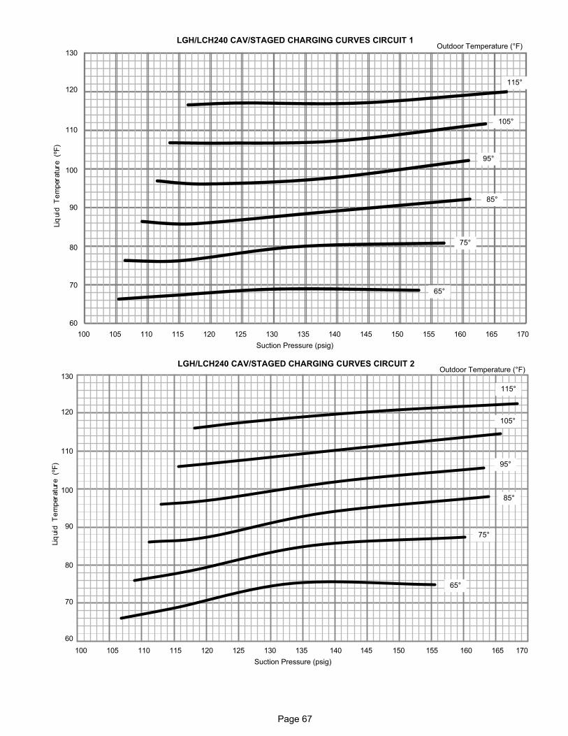
Page 67
100 105 110 115 120 125 130 135 140 145 150 155 160 165 170
Suction Pressure (psig)
60
70
80
90
100
110
120
130
115°
105°
95°
85°
75°
65°
Outdoor Temperature (°F)LGH/LCH240 CAV/STAGED CHARGING CURVES CIRCUIT 1
100 105 110 115 120 125 130 135 140 145 150 155 160 165 170
Suction Pressure (psig)
115°
105°
95°
85°
75°
65°
Outdoor Temperature (°F)
60
70
80
90
100
110
120
130
LGH/LCH240 CAV/STAGED CHARGING CURVES CIRCUIT 2

Page 68
100 105 110 115 120 125 130 135 140 145 150 155 160 165 170
Suction Pressure (psig)
115°
105°
95°
85°
75°
65°
Outdoor Temperature (°F)
70
80
90
100
110
120
130
LGH/LCH240 CAV/STAGED CHARGING CURVES CIRCUIT 3
100 105 110 115 120 125 130 135 140 145 150 155 160 165 170
Suction Pressure (psig)
115°
105°
95°
85°
75°
65°
Outdoor Temperature (°F)
70
80
90
100
110
120
130
LGH/LCH240 CAV/STAGED CHARGING CURVES CIRCUIT 4

Page 69
110 120 130 140 150 160 170Suction Pressure (psig)
115°
105°
95°
85°
75°
65°
Outdoor Temperature (°F)
70
80
90
100
110
120
130
180
LGH/LCH240 CAV/STAGED REHEAT CHARGING CURVES CIRCUIT 1
110 120 130 140 150 160 170Suction Pressure (psig)
115°
105°
95°
85°
75°
65°
Outdoor Temperature (°F)
70
80
90
100
110
120
130
10060
LGH/LCH240 CAV/STAGED REHEAT CHARGING CURVES CIRCUIT 2

Page 70
110 120 130 140 150 160 170Suction Pressure (psig)
115°
105°
95°
85°
75°
65°
Outdoor Temperature (°F)
70
80
90
100
110
120
130
180
LGH/LCH240 CAV/STAGED REHEAT CHARGING CURVES CIRCUIT 3
110 120 130 140 150 160 170Suction Pressure (psig)
115°
105°
95°
85°
75°
65°
Outdoor Temperature (°F)
70
80
90
100
110
120
130
LGH/LCH240 CAV/STAGED REHEAT CHARGING CURVES CIRCUIT 4
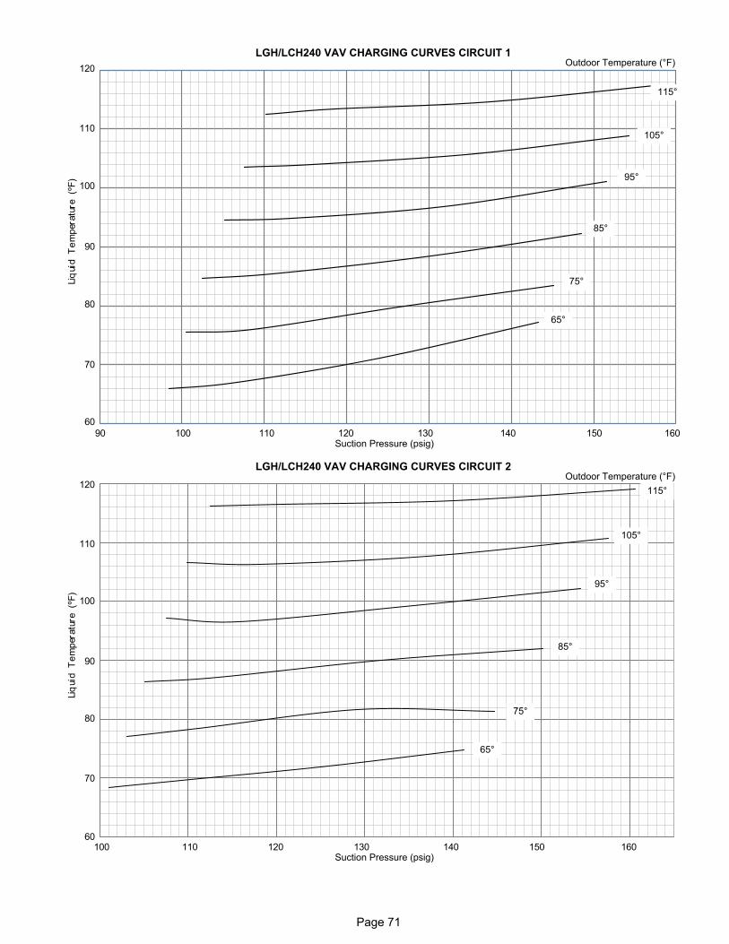
Page 71
110 120 130 140 150 160Suction Pressure (psig)
115°
105°
95°
85°
75°
65°
Outdoor Temperature (°F)
70
80
90
100
110
120
LGH/LCH240 VAV CHARGING CURVES CIRCUIT 1
10090
60
110 120 130 140 150 160Suction Pressure (psig)
115°
105°
95°
85°
75°
65°
Outdoor Temperature (°F)
70
80
90
100
110
120
LGH/LCH240 VAV CHARGING CURVES CIRCUIT 2
60100

Page 72
110 120 130 140 150 160 170Suction Pressure (psig)
115°
105°
95°
85°
75°
65°
Outdoor Temperature (°F)
70
80
90
100
110
120
LGH/LCH240 VAV CHARGING CURVES CIRCUIT 3
60
110 120 130 140 150 160 170Suction Pressure (psig)
115°
105°
95°
85°
75°
65°
Outdoor Temperature (°F)
70
80
90
100
110
120
130
LGH/LCH240 VAV CHARGING CURVES CIRCUIT 4
180

Page 73
70
80
90
100
110
120
110 120 130 140 150 160 170
LGH/LCH300S CHARGING CURVE CIRCUIT 1
Suction Pressure (psig)
Outdoor Temperature (°F)
115°
105°
95°
85°
75°
65°
130
100
70
80
90
100
110
120
110 120 130 140 150 160 170
LGH/LCH300S CHARGING CURVE CIRCUIT 2
Suction Pressure (psig)
Outdoor Temperature (°F)
115°
105°
95°
85°
75°
65°
130
100

Page 74
70
80
90
100
110
120
110 120 130 140 150 160 170
LGH/LCH300S CHARGING CURVE CIRCUIT 3
Suction Pressure (psig)
Outdoor Temperature (°F)
115°
105°
95°
85°
75°
65°
130
100
70
80
90
100
110
120
110 120 130 140 150 160 170
LGH/LCH300S CHARGING CURVE CIRCUIT 4
Suction Pressure (psig)
Outdoor Temperature (°F)
115°
105°
95°
85°
75°
65°
100
130

Page 75
70
80
90
100
110
120
110 120 130 140 150 160 170
LGH/LCH300S REHEAT CHARGING CURVE CIRCUIT 1
Suction Pressure (psig)
Outdoor Temperature (°F)
115°
105°
95°
85°
75°
65°
130
100
70
80
90
100
110
120
110 120 130 140 150 160 170
LGH/LCH300S REHEAT CHARGING CURVE CIRCUIT 2
Suction Pressure (psig)
Outdoor Temperature (°F)
115°
105°
95°
85°
75°
65°
130
10060

Page 76
70
80
90
100
110
120
110 120 130 140 150 160 170
LGH/LCH300S REHEAT CHARGING CURVE CIRCUIT 3
Suction Pressure (psig)
Outdoor Temperature (°F)
115°
105°
95°
85°
75°
65°
130
140
180100
70
80
90
100
110
120
110 120 130 140 150 160 170
LGH/LCH300S REHEAT CHARGING CURVE CIRCUIT 4
Suction Pressure (psig)
Outdoor Temperature (°F)
115°
105°
95°
85°
75°
65°
130
100
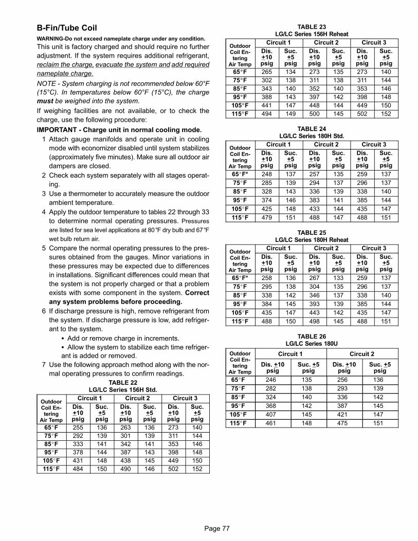
Page 77
B-Fin/Tube Coil
WARNING-Do not exceed nameplate charge under any condition.
This unit is factory charged and should require no further
adjustment. If the system requires additional refrigerant,
reclaim the charge, evacuate the system and add required
nameplate charge.
NOTE - System charging is not recommended below 60°F
(15°C). In temperatures below 60°F (15°C), the charge
must be weighed into the system.
If weighing facilities are not available, or to check the
charge, use the following procedure:
IMPORTANT - Charge unit in normal cooling mode.
1 Attach gauge manifolds and operate unit in cooling
mode with economizer disabled until system stabilizes
(approximately five minutes). Make sure all outdoor air
dampers are closed.
2 Check each system separately with all stages operat
ing.
3 Use a thermometer to accurately measure the outdoor
ambient temperature.
4 Apply the outdoor temperature to tables 22 through 33
to determine normal operating pressures. Pressures
are listed for sea level applications at 80°F dry bulb and 67°F
wet bulb return air.
5 Compare the normal operating pressures to the pres
sures obtained from the gauges. Minor variations in
these pressures may be expected due to differences
in installations. Significant differences could mean that
the system is not properly charged or that a problem
exists with some component in the system. Correct
any system problems before proceeding.
6 If discharge pressure is high, remove refrigerant from
the system. If discharge pressure is low, add refriger
ant to the system.
� Add or remove charge in increments.
� Allow the system to stabilize each time refriger
ant is added or removed.
7 Use the following approach method along with the nor
mal operating pressures to confirm readings.
TABLE 22LG/LC Series 156H Std.
OutdoorCoil Entering
Air Temp
Circuit 1 Circuit 2 Circuit 3
Dis.+10psig
Suc.+5
psig
Dis.+10psig
Suc.+5
psig
Dis.+10psig
Suc.+5
psig
65�F 255 136 263 136 273 140
75�F 292 139 301 139 311 144
85�F 333 141 342 141 353 146
95�F 378 144 387 143 398 148
105�F 431 148 438 145 449 150
115�F 484 150 490 146 502 152
TABLE 23LG/LC Series 156H Reheat
OutdoorCoil Entering
Air Temp
Circuit 1 Circuit 2 Circuit 3
Dis.+10psig
Suc.+5
psig
Dis.+10psig
Suc.+5
psig
Dis.+10psig
Suc.+5
psig
65�F 265 134 273 135 273 140
75�F 302 138 311 138 311 144
85�F 343 140 352 140 353 146
95�F 388 143 397 142 398 148
105�F 441 147 448 144 449 150
115�F 494 149 500 145 502 152
TABLE 24LG/LC Series 180H Std.
OutdoorCoil Entering
Air Temp
Circuit 1 Circuit 2 Circuit 3
Dis.+10psig
Suc.+5
psig
Dis.+10psig
Suc.+5
psig
Dis.+10psig
Suc.+5
psig
65�F* 248 137 257 135 259 137
75�F 285 139 294 137 296 137
85�F 328 143 336 139 338 140
95�F 374 146 383 141 385 144
105�F 425 148 433 144 435 147
115�F 479 151 488 147 488 151
TABLE 25LG/LC Series 180H Reheat
OutdoorCoil Entering
Air Temp
Circuit 1 Circuit 2 Circuit 3
Dis.+10psig
Suc.+5
psig
Dis.+10psig
Suc.+5
psig
Dis.+10psig
Suc.+5
psig
65�F* 258 136 267 133 259 137
75�F 295 138 304 135 296 137
85�F 338 142 346 137 338 140
95�F 384 145 393 139 385 144
105�F 435 147 443 142 435 147
115�F 488 150 498 145 488 151
TABLE 26LG/LC Series 180U
OutdoorCoil Entering
Air Temp
Circuit 1 Circuit 2
Dis. +10psig
Suc. +5psig
Dis. +10psig
Suc. +5psig
65�F 246 135 256 136
75�F 282 138 293 139
85�F 324 140 336 142
95�F 368 142 387 145
105�F 407 145 421 147
115�F 461 148 475 151

Page 78
TABLE 27LG/LC Series 210H Std.
OutdoorCoil Entering
Air Temp
Circuit 1 Circuit 2 Circuit 3
Dis.+10psig
Suc.+5
psig
Dis.+10psig
Suc.+5
psig
Dis.+10psig
Suc.+5
psig
65�F* 246 138 252 142 264 138
75�F 284 142 294 145 306 140
85�F 326 145 335 147 348 142
95�F 373 148 380 149 393 144
105�F 422 150 430 151 441 145
115�F 472 153 482 154 492 148
TABLE 28LG/LC Series 210H Reheat
OutdoorCoil Entering
Air Temp
Circuit 1 Circuit 2 Circuit 3
Dis.+10psig
Suc.+5
psig
Dis.+10psig
Suc.+5
psig
Dis.+10psig
Suc.+5
psig
65�F* 258 136 264 141 264 138
75�F 296 140 306 144 306 140
85�F 338 143 347 146 348 142
95�F 385 146 392 148 393 144
105�F 434 148 442 150 441 145
115�F 484 151 494 153 492 148
TABLE 29LG/LC Series 240H Std.
OutdoorCoil Entering
Air Temp
Circuit 1 Circuit 2 Circuit 3 Circuit 4
Dis.+10psig
Suc.+5
psig
Dis.+10psig
Suc.+5
psig
Dis.+10psig
Suc.+5
psig
Dis.+10psig
Suc.+5
psig
65�F* 255 137 246 132 260 141 252 135
75�F 291 140 284 137 298 144 290 137
85�F 332 142 325 140 340 146 331 139
95�F 378 145 371 142 385 148 377 141
105�F 428 148 421 145 436 150 428 143
115�F 481 151 473 148 488 153 479 145
TABLE 30LG/LC Series 240H Reheat
OutdoorCoil Entering
Air Temp
Circuit 1 Circuit 2 Circuit 3 Circuit 4
Dis.+10psig
Suc.+5
psig
Dis.+10psig
Suc.+5
psig
Dis.+10psig
Suc.+5
psig
Dis.+10psig
Suc.+5
psig
65�F* 270 13 261 130 260 141 252 135
75�F 306 137 299 135 298 144 290 137
85�F 347 140 340 137 340 146 331 139
95�F 393 143 386 140 385 148 377 141
105�F 443 145 436 143 436 150 428 143
115�F 496 148 488 145 488 153 479 145
TABLE 31LG/LC Series 240U
OutdoorCoil Entering
Air Temp
Circuit 1 Circuit 2
Dis. +10psig
Suc. +5psig
Dis. +10psig
Suc. +5psig
65�F 251 127 262 128
75�F 290 132 303 133
85�F 331 135 347 136
95�F 376 137 394 139
105�F 426 141 443 142
115�F 479 144 495 145
TABLE 32LG/LC Series 300S Std.
OutdoorCoil Entering
Air Temp
Circuit 1 Circuit 2 Circuit 3 Circuit 4
Dis.+10psig
Suc.+5
psig
Dis.+10psig
Suc.+5
psig
Dis.+10psig
Suc.+5
psig
Dis.+10psig
Suc.+5
psig
°65�F* 272 129 273 128 280 129 277 127
75�F 311 132 303 131 321 131 317 129
85�F 357 134 349 133 367 133 363 130
95�F 403 137 397 137 418 135 406 134
105�F 451 139 453 140 475 138 471 136
115�F 502 142 506 142 532 144 529 140
TABLE 33LG/LC Series 300S Reheat
OutdoorCoil Entering
Air Temp
Circuit 1 Circuit 2 Circuit 3 Circuit 4
Dis.+10psig
Suc.+5
psig
Dis.+10psig
Suc.+5
psig
Dis.+10psig
Suc.+5
psig
Dis.+10psig
Suc.+5
psig
°65�F* 285 128 284 128 280 129 277 127
75�F 324 132 315 130 321 131 317 129
85�F 368 134 358 132 367 133 363 130
95�F 418 136 406 136 418 136 406 135
105�F 466 138 462 138 475 138 471 136
115�F 517 141 515 141 532 144 529 140
TABLE 34LG/LC Series 300U Std. - 580965-01
OutdoorCoil Entering
Air Temp
Circuit 1 Circuit 2
Dis. +10psig
Suc. +5psig
Dis. +10psig
Suc. +5psig
65°F 268 119 265 113
75°F 313 128 309 120
85°F 358 135 351 126
95°F 409 140 405 131
105°F 470 143 463 136
115°F 532 151 505 127
C-Charge Verification - Approach Method - AHRI
Testing (Fin/Tube Coil)
1 Using the same thermometer, compare liquid temper
ature to outdoor ambient temperature.
Approach Temperature = Liquid temperature (at con
denser outlet) minus ambient temperature.
2 Approach temperature should match values in table
35. An approach temperature greater than value
shown indicates an undercharge. An approach tem
perature less than value shown indicates an over
charge.

Page 79
3 The approach method is not valid for grossly over or
undercharged systems. Use tables 22 through 33 as a
guide for typical operating pressures.
TABLE 35APPROACH TEMPERATURES - FIN/TUBE COIL
L SeriesUnit
Liquid Temp. Minus Ambient Temp.
1st Stage 2nd Stage 3rd Stage 4th Stage
156H Std.9°F + 1
(5.0°C +0.5)9°F + 1
(5.0°C +0.5)11°F + 1
(6.1°C +0.5) NA
156HReheat
6°F+1(3.3°C+0.5)
6°F+1(3.3°C+0.5)
11°F+1(6.1°C+0.5) NA
180H Std.6°F + 1
(3.3°C +0.5)6°F + 1
(3.3°C +0.5)6°F + 1
(3.3°C +0.5) NA
180HReheat
4°F + 1 (2.2°C +0.5)
4°F + 1 (2.2°C +0.5)
6°F + 1 (3.3°C +0.5) NA
180U5°F + 1
(2.8°C +0.5)6.5°F + 1
(3.6°C +0.5) NA NA
210H Std.6°F + 1
(3.3°C +0.5)6°F + 1
(3.3°C +0.5)7°F + 1
(3.9°C +0.5) NA
210HReheat
4°F + 1 (2.2°C +0.5)
4°F + 1 (2.2°C +0.5)
7°F + 1 (3.9°C +0.5) NA
240H Std.6°F + 1
(3.3°C +0.5)6°F + 1
(3.3°C +0.5)7°F + 1
(3.9°C +0.5)7°F + 1
(3.9°C +0.5)
240HReheat
4°F + 1 (2.2°C +0.5)
4°F + 1 (2.2°C+0.5)
8°F + 1 (4.4°C +0.5)
8°F + 1 (4.4°C +0.5)
240U4°F + 1
(2.2°C +0.5)6.5°F + 1
(3.6°C +0.5) NA NA
300S Std.5°F+1
(2.8°C+0.5)5°F+1
(2.8°C+0.5)8°F+1
(4.4°C+0.5)8°F+1
(4.4°C+0.5)
300SReheat
3°F+1(1.7°C+0.5)
3°F+1(1.7°C+0.5)
8°F+1(4.4°C+0.5)
8°F+1(4.4°C+0.5)
300U4°F + 1
(2.2°C +0.5)10°F + 1
(5.5°C +0.5) NA NA
IV-STARTUP - OPERATION
Refer to startup directions and to the unit wiring diagram
when servicing. See unit nameplate for minimum circuit
ampacity and maximum fuse size.
A-Preliminary and Seasonal Checks
1- Make sure the unit is installed in accordance with the
installation instructions and applicable codes.
2- Inspect all electrical wiring, both field and factory installed
for loose connections. Tighten as required. Refer to unit
diagram located on inside of unit control box cover.
3- Check to ensure that refrigerant lines are in good
condition and do not rub against the cabinet or other
refrigerant lines.
4- Check voltage. Voltage must be within the range list
ed on the nameplate. If not, consult power company
and have the voltage corrected before starting the
unit.
5- Recheck voltage and amp draw with unit running. If
voltage is not within range listed on unit nameplate,
stop unit and consult power company. Refer to unit
nameplate for maximum rated load amps.
6- Inspect and adjust blower belt (see section on Blower
Compartment - Blower Belt Adjustment).
B-Cooling Startup See figures 19 and 20 forcircuits
NOTE-Crankcase heaters must be energized 24 hours be
fore attempting to start compressor. Set thermostat so that
there is no demand to prevent compressor from cycling.
Apply power to unit.
1- Initiate first and second stage cooling demands ac
cording to instructions provided with thermostat.
2- .First-stage thermostat demand will energize com
pressors 1 and 2 on all standard and high efficient
units. Second-stage thermostat demand will energize
compressor 3 on all standard and high efficiency units
and compressor 4 on LCH240H/300. First-stage ther
mostat demand will energize one compressor from
each circuit on ultra high efficiency units. Second-
stage thermostat demand will energize the remaining
two compressors, one in each circuit, on ultra high effi
ciency units.
3- Units contain three or four refrigerant circuits or stages.
4- Each refrigerant circuit is separately charged with re
frigerant. See unit rating plate for correct amount of
charge.
NOTE - Refer to III-CHARGING for proper method to check
refrigerant charge.
C-Three Phase Scroll Compressor Voltage
Phasing
Three phase scroll compressors must be phased se
quentially to ensure correct compressor and blower rota
tion and operation. Compressor and blower are wired in
phase at the factory. Power wires are color-coded as fol
lows: line 1-red, line 2-yellow, line 3-blue.
1- Observe suction and discharge pressures and blower
rotation on unit start-up.
2- Suction pressure must drop, discharge pressure must
rise and blower rotation must match rotation marking.
If pressure differential is not observed or blower rotation is
not correct:
3- Disconnect all remote electrical power supplies.
4- Reverse any two field-installed wires connected to the
line side of S48 disconnect or TB13 terminal strip. Do
not reverse wires at blower contactor.
5- Make sure the connections are tight.
Discharge and suction pressures should operate at their
normal start‐up ranges.
D-Safety or Emergency Shutdown
Turn off power to the unit.

Page 80
FIGURE 19
EVAPORATORCOIL
STAGE 1CONDENSER
COILS
156, 180H, & 210 REFRIGERANT CIRCUITS
STAGE 2CONDENSER
COILS
STAGE 1EVAPORATOR
COIL
STAGE 2EVAPORATOR
COIL
156/180 VAV ONLYEVAPORATOR COIL
(not to scale)
STAGE 1CIRCUIT 1
STAGE 3CIRCUIT 1, 2, & 3
STAGE 2CIRCUIT 1 & 2INTERTWINED
STAGE 4CIRCUITS1, 2, 3, & 4
INTERTWINED
EVAPORATORCOIL
STAGE 1CONDENSER
COIL
240H & 300S REFRIGERANT CIRCUITS
STAGE 2CONDENSER COIL
STAGE 1EVAPORATOR
COIL
STAGE 2EVAPORATOR
COIL
240 VAV ONLYEVAPORATOR
COIL(not to scale)
STAGE 1CIRCUIT 1
STAGE 2CIRCUITS 1 & 2INTERTWINED
STAGE 3CIRCUITS 1, 2, & 3
INTERTWINED

Page 81
FIGURE 20
CIRCUIT 1 AND 2ALTERNATE THROUGH THE
EVAPORATOR COIL(not to scale)
CIRCUIT 1CONDENSER COIL
REFRIGERANT CIRCUITS - 180U, 240U, 300U
CIRCUIT 2CONDENSER COIL
CIRCUIT 1 -COMPRESSOR 1 AND 2
CIRCUIT 2 -COMPRESSOR 3 AND 4
Y1=Compressor 1 or 2 AND Compressor 3 or 4Y2=Compressor 1, 2, 3, 4
180U, 240U, 300U COMPRESSOR DETAIL

Page 82
V- SYSTEMS SERVICE CHECKS
A-Cooling System Service ChecksLCH units are factory charged and require no further adjust
ment; however, charge should be checked periodically using
the approach method. The approach method compares actual
liquid temperature with the outdoor ambient temperature. See
section III- CHARGING.
NOTE-When unit is properly charged discharge line pres
sures should approximate those in tables 9 through 33.
VI-MAINTENANCE
Electric shock hazard. Can causeinjury or death. Before attempting toperform any service or maintenance,turn the electrical power to unit OFFat disconnect switch(es). Unit may
have multiple power supplies.
WARNING!
A-FiltersUnits use six 24 X 24 X 2” pleated throw-away type filters.
Filters may be accessed through the economizer / filter
access door. Filters should be checked monthly (or more
frequently in severe use) and cleaned or replaced regu
larly. Take note of the “AIR FLOW DIRECTION” marking
on the filter frame when re-installing.
B-Lubrication
All motors and blower wheels used in LCH units are pre
lubricated; no further lubrication is required.
C-Supply Air Blower Wheel
Annually inspect supply air blower wheel for accumulated
dirt or dust. Turn off power before attempting to remove
access panel or to clean blower wheel.
D-Evaporator Coil
Inspect and clean coil at beginning of each season. Clean
using mild detergent or commercial coil cleanser. Check
condensate drain pan and line, if necessary. Flush coil and
condensate drain with water taking care not to get insula
tion, filters and return air ducts wet. Check connecting
lines and coil for evidence of oil and refrigerant leaks.
E-Condenser Coil
Clean condenser coil annually with detergent or com
mercial coil cleaner and inspect monthly during the cool
ing season. Check connecting lines and coil for evidence
of oil and refrigerant leaks.
NOTE-If owner complains of insufficient cooling, the
unit should be gauged and refrigerant charge checked.
Refer to Gauge Manifold Attachment and Charging
sections in this manual.
F-Electrical1- Check all wiring for loose connections.
2- Check for correct voltage at unit (unit operating).
3- Check amp-draw on both condenser fan motor andblower motor. Fan Motor Rating Plate ____ Actual ________Indoor Blower Motor Rating Plate____ Actual____
VII-ACCESSORIES The accessories section describes the application of most of
the optional accessories which can be factory or field installed
to the LCH units.
A-LARMF and LARMFH Mounting Frames
When installing either the LCH units on a combustible sur
face for downflow discharge applications, the Lennox
LARMF18/36 14‐inch or 24‐inch (356 mm or 610mm)
height roof mounting frame is used. For horizontal dis
charge applications, use LARMFH18/24 26‐inch or
37‐inch (660mm or 940mm) height roof mounting frame.
This frame converts unit from down‐flow to horizontal air
flow. The 37 inch (940mm) horizontal frame meets Nation
al Roofing Code requirements. The roof mounting frames
are recommended in all other applications but not re
quired. If the LCH units are not mounted on a flat (roof)
surface, they MUST be supported under all edges and un
der the middle of the unit to prevent sagging. The units
MUST be mounted level within 1/16” per linear foot or
5mm per meter in any direction.
The assembled LARMF18/36 mounting frame is shown in
figure 21. Refer to the roof mounting frame installation in
structions for details of proper assembly and mounting.
The roof mounting frame MUST be squared to the roof and
level before mounting. Plenum system MUST be installed
before the unit is set on the mounting frame. Typical roof
curbing and flashing is shown in figure 22. Refer to the roof
mounting frame installation instructions for proper plenum
construction and attachment.
B-Control Systems
The A55 Unit Controller provides all control function for the
rooftop unit. Default operation requires a standard room
thermostat or direct digital controller (DDC). The A55 can
also control the unit from a zone temperature sensor. The
A55 Unit Controller is a network controller when daisy-
chained to the L Connection® Network Control System. For
ease of configuration, the A55 can be connected to a PC
with Unit Controller PC software installed.

Page 83
FIGURE 21
ASSEMBLED ROOF MOUNTING FRAME
FRONT
END
END
BACK
CENTER SUPPORTS(TWO PIECES EACH)
FIGURE 22
ROOFMOUNTING FRAME
(Extends around entireperimeter of unit)
FIBERGLASSINSULATION(Furnished)
COUNTER FLASHING(Field Supplied)
UNIT BASEBOTTOM
RIGID INSULATION(Field Supplied)
ROOFINGMATERIAL
CANT STRIP(Field Supplied)
NAILER STRIP(Furnished)
UNIT BASERAIL
TYPICAL FLASHING DETAIL
C-Transitions
Optional supply/return transitions LASRT18/24 are avail
able for use with LCH series units utilizing optional
LARMF18/36 roof mounting frame. Transition must be in
stalled in the LARMF18/36 mounting frame before mount
ing the unit to the frame. Refer to the manufacturer's in
structions included with the transition for detailed
installation procedures.
D-Supply and Return Diffusers
Optional flush mount diffuser/return FD11 and extended
mount diffuser/return RTD11 are available for use with all LCH
units. Refer to manufacturer's instructions included with
transition for detailed installation procedures.
E-C1DAMP10 & E1DAMP20 Outdoor AirDampers
C1DAMP10C and E1DAMP20C (figure 23) consist of a set
of dampers which may be manually or motor operated to
allow up to 25 percent outside air into the system at all
times (see figure 23). Either air damper can be installed in
LCH units. Washable filter supplied with the outdoor air
dampers can be cleaned with water and a mild detergent. It
should be sprayed with Filter Handicoater when dry prior to
reinstallation. Filter Handicoater is R.P. Products coating
no. 418 and is available as Part No. P-8-5069.
F-E1ECON15C-2 Standard and E1ECON17C-1High Performance Economizer (Field or Factory Installed)
The optional E1ECON15 economizer can be used with
downflow and horizontal air discharge applications. The econ
omizer uses outdoor air for free cooling when temperature
and/or humidity is suitable. An economizer hood is furnished
with the economizer.
The economizer is controlled by the A55 Unit Controller.
The economizer will operate in one of four modes. Each
mode requires a different A55 Unit Controller DIP switch set
ting. Each mode also requires different sensors.
The following is a brief description. See economizer installa
tion instruction for more detail.
1-“TMP” MODE (SENSIBLE TEMPERATURE)
In the “TMP” mode, the IMC uses input from the factory in
stalled RT6 Supply Air Sensor, RT16 Return Air Sensor and
RT17 Outdoor Air Sensor to determine suitability of outside air
and economizer damper operation. When outdoor sensible
temperature is less than return air sensible temperature, out
door air is used for cooling. This may be supplemented by me
chanical cooling to meet comfort demands. This application
does not require additional optional sensors.
2-“ODE” MODE (OUTDOOR ENTHALPY)
The “ODE” or outdoor enthalpy mode requires a field-pro
vided and -installed Honeywell C7400 enthalpy sensor
(16K96). The sensor monitors outdoor air temperature
and humidity (enthalpy). When outdoor air enthalpy is be
low the enthalpy control setpoint, the economizer modu
lates to allow outdoor air for free cooling.
3-“DIF” MODE (DIFFERENTIAL ENTHALPY)
The “DIF” or differential enthalpy mode requires two field-pro
vided and -installed Honeywell C7400 enthalpy sensors
(16K97). One sensor is installed in the outside air opening
and the other sensor is installed in the return air opening.
When the outdoor air enthalpy is below the return air en
thalpy, the economizer opens to bring in outdoor air for
free cooling.

Page 84
E1DAMP20 MOTORIZED OUTDOOR AIR DAMPER
C1DAMP10 MANUAL OUTDOOR AIR DAMPER
FIGURE 23
FILTER BRACKET SIDE VIEW
HOOD TOP
FILTER
HOOD TOP SEAL
4-“GLO” MODE (GLOBAL)
Global Mode - The “GLO” or global mode is used with an
energy management system which includes a global con
trol feature. Global control is used when multiple units (in
one location) respond to a single outdoor air sensor. Each
energy management system uses a specific type of out
door sensor which is installed and wired by the controls
contractor.
Motorized Outdoor Air Damper - The “GLO” mode is also
used when a motorized outdoor air damper is installed in
the system.
NOTE - All economizer modes of operation will mod
ulate dampers to 55�F (13�C) supply air.
G-Gravity Exhaust Dampers
C1DAMP50C dampers (figure 24) are used in downflow
and LAGEDH are used in horizontal air discharge applica
tions. LAGEDH gravity exhaust dampers are installed in
the return air plenum . The dampers must be used any time
an economizer or power exhaust fans are applied to LCH
series units. An exhaust hood is furnished with the gravity
exhaust damper.
Gravity exhaust dampers allow exhaust air to be dis
charged from the system when an economizer and/or pow
er exhaust is operating. Gravity exhaust dampers also pre
vent outdoor air infiltration during unit off cycle. See
installation instructions for more detail.
NOTE - Gravity exhaust dampers are required with power
exhaust.
FIGURE 24
LAPEFPOWER EXHAUSTFAN ASSEMBLY
LAGED GRAVITYEXHAUST DAMPERS
ECONOMIZERFRESH AIR
HOOD
P18
LAGED AND LAPEF INSTALLATION
H-C1PWRE10 Power Exhaust Fans
C1PWRE10 power exhaust fans are used in downflow appli
cations only. C1PWRE10 fans require optional downflow grav
ity exhaust dampers and E1ECON15 economizers. Power ex
haust fans provide exhaust air pressure relief and also run
when return air dampers are closed and supply air blowers
are operating. Figure 24 shows the location of the power ex
haust fans. See installation instructions for more detail.
I-Smoke Detectors A171, A172, A173
Photoelectric smoke detectors are a factory- and field-in
stalled option. The smoke detectors can be installed in the
supply air section (A172), return air section (A171), or in
both the supply and return air section. Smoke detection con
trol module (A173) is located below the control panel. Wiring
for the smoke detectors are shown on the temperature con
trol section (C) wiring diagram in back of this manual.

Page 85
J-Blower Proving Switch S52The blower proving switch monitors blower operation and
locks out the unit in case of blower failure. The switch is
N.O. and closes at .15” W.C. (3.3 Pa) The switch is mount
ed on the middle left corner of the blower support panel.
Wiring for the blower proving switch is shown on the tem
perature control section (C) wiring diagram in back of this
manual.
K-Indoor Air Quality (CO2) Sensor A63The indoor air quality sensor monitors CO2 levels and re
ports the levels to the A55 Unit Controller. The board ad
justs the economizer dampers according to the CO2 levels.
The sensor is mounted next to the indoor thermostat or in
the return air duct. Refer to the indoor air quality sensor in
stallation instructions for proper adjustment. Wiring for the
indoor air quality switch is shown on the temperature con
trol section (C) wiring diagram in back of this manual.
L-Dirty Filter Switch S27
The dirty filter switch senses static pressure increase indi
cating a dirty filter condition. The switch is N.O. and closes
at 1” W.C. (248.6 Pa) The switch is mounted on the top cor
ner of the economizer. Wiring for the dirty filter switch is
shown on the temperature control section (C) wiring diagram
in back of this manual.
M-Optional UVC Lights
The Healthy Climate® germicidal light emits ultraviolet
(UVC) energy that has been proven effective in reducing
microbial life forms (viruses, bacteria, yeasts and molds) in
the air.
UVC germicidal lamps greatly reduce the growth and prolif
eration of mold and other bio-aerosols (bacteria and virus
es) on illuminated surfaces.
Germicidal lamps are NOT intended to be used for removal
of active mold growth. Existing mold growth must be appro
priately removed PRIOR to installation of the germicidal
lamp.
Refer closely to UVC light installation instruction warnings
when servicing units.
N-Drain Pan Overflow Switch S149 (optional)
The overflow switch is used to interrupt cooling operation
when excessive condensate collects in the drain pan. The
N.O. overflow switch is controlled by K220 and DL46 re
lays, located in the unit control panel. When the overflow
switch closes, 24VAC power is interrupted and after a five-
second delay unit compressors are de-energized. Once
the condensate level drops below the set level, the switch
will open. After a five-minute delay the compressor will be
energized.
P-Factory-Installed Hotgas Reheat
General
Hotgas Reheat units provide a dehumidifying mode of op
eration. These units contain a reheat coil adjacent to and
downstream of the evaporator coil. Reheat coil solenoid
valves, L14 and L30, route hot discharge gas from the
compressor to the reheat coil. Return air pulled across the
evaporator coil is cooled and dehumidified; the reheat coil
adds heat to supply air.
See figure 25 for 156, 180 and 210 reheat refrigerant rout
ing, figure 26 for 156, 180 and 210 normal cooling refriger
ant routing, figure 27 for 240 and 300S reheat refrigerant
routing and figure 28 for 240 and 300S normal cooling re
frigerant routing.
L14 and L30 Reheat Coil Solenoid Valves
When Unit Controller (P298-5 or J299-8) indicates room
conditions require dehumidification, L14 and L30 reheat
valves are energized (Unit Controller P269-3 or P269-4)
and refrigerant is routed to the reheat coil.
Reheat Setpoint
Reheat is factory-set to energize when indoor relative hu
midity rises above 60% (default). The reheat setpoint can
be adjusted by changing Unit Controller Settings - Control
menu. A setting of 100% will operate reheat from an energy
management system digital output. The reheat setpoint
can also be adjusted using an optional Network Control
Panel (NCP).
Reheat will terminate when the indoor relative humidity
falls 3% (57% default) or the digital output de-energizes.
The reheat deadband can be adjusted at Settings - Control
menu.
A91 Humidity Sensor
Relative humidity should correspond to the sensor (A91)
output voltage listed in table 36. For example: if indoor air
relative humidity is 80% + 3%, the humidity sensor output
should read 8.00VDC.
Check the sensor output annually for accuracy. Keep the
air intake openings on the sensor clean and free of obstruc
tions and debris.
TABLE 36
Relative Humidity (%RH + 3%) Sensor Output (VDC)
20 2.00
30 3.00
40 4.00
50 5.00
60 6.00
70 7.00
80 8.00
90 9.00

Page 86
REHEAT MODE REFRIGERANT ROUTING156, 180H, & 210 UNITS
REHEATCOIL
CIRCUIT 1CONDENSER
COIL
CIRCUIT 2CONDENSER
COIL
STAGE 2EVAPORATOR
COIL
STAGE 1EVAPORATOR
COIL
1
2
EXPANSIONVALVES
CHECKVALVE
L14REHEATVALVE
L30REHEATVALVE
3
CHECKVALVE
Note: Two refrigerant circuits are shown;both circuits operate during reheat.
FIGURE 25
COOLING MODE REFRIGERANT ROUTING156, 180H, & 210 UNITS
REHEATCOIL
CIRCUIT 1CONDENSER
COIL
CIRCUIT 2CONDENSER
COIL
STAGE 2EVAPORATOR
COIL
STAGE 1EVAPORATOR
COIL
1
2
EXPANSIONVALVES
CHECKVALVE
L14REHEATVALVE
L30REHEATVALVE
3
CHECKVALVE
Note: Two refrigerant circuits are shown;both circuits operate when there is afirst-stage thermostat demand (default).
FIGURE 26

Page 87
4
REHEAT MODE REFRIGERANT ROUTING240H AND 300S UNITS
REHEATCOIL
CIRCUIT 1CONDENSER
COIL
CIRCUIT 2CONDENSER
COIL
1
2
EXPANSIONVALVES
CHECKVALVE
L14REHEATVALVE
L30REHEATVALVE
3
CHECKVALVE
STAGE 1EVAPORATOR
COIL
STAGE 2EVAPORATOR
COIL
Note: Two refrigerant circuits are shown;both circuits operate during reheat.
FIGURE 27
4
COOLING MODE REFRIGERANT ROUTING240H AND 300S UNITS
REHEATCOIL
CIRCUIT 1CONDENSER
COIL
CIRCUIT 2CONDENSER
COIL
1
2
EXPANSIONVALVES
CHECKVALVE
L14REHEATVALVE L30
REHEATVALVE
3
CHECKVALVE
STAGE 1EVAPORATOR
COIL
STAGE 2EVAPORATOR
COIL
Note: Two refrigerant circuits are shown;both circuits operate when there is afirst-stage thermostat demand (default).
FIGURE 28

Page 88
WARNINGProduct contains fiberglass wool.Disturbing the insulation in this product duringinstallation, maintenance, or repair will expose youto fiberglass wool. Breathing this may cause lungcancer. (Fiberglass wool is known to the State of California to cause cancer.)Fiberglass wool may also cause respiratory, skinand eye irritation.To reduce exposure to this substance or for furtherinformation, consult material safety data sheetsavailable from address shown on unit nameplate orcontact your supervisor.
Check-Out
Test Humiditrol operation using the following procedure.
1 Make sure reheat is wired as shown in wiring section.
2 Make sure unit is in local thermostat mode.
3 Select Unit Controller Service - Test.
The blower, compressor 1 and compressor 2 (reheat) should
be operating. Reheat mode will appear on the Unit Controller
display.
4 Deselect Unit Controller Service - Test.
Compressor 1 and 2 (reheat) should de-energize,, blower
should still be energized.
Default Reheat Operation
Reheat will operate as shown in table 37 once three condi
tions are met:
1 Blower must be operating.
2 System must be in occupied mode.
3 System must NOT be operating in heating mode.
IMPORTANT - Free cooling does not operate during re
heat.
For other reheat control options, refer to the Unit Controller
manual.
Additional Cooling Stages
Units are shipped from the factory to provide two stages of
cooling.
Three stages of cooling is available in zone sensor mode.
Three stages of cooling is also available by installing a transfer
relay and a three-stage thermostat. Refer to the Main Control
Operation section in the Unit Controller manual when using the
transfer relay.
Four stages of cooling is available in zone sensor mode on
units with four compressors (240, 300S).
Compressors are not de-energized when unit operation
changes from cooling to reheat or from reheat to cooling.
Instead, L14 and L30 reheat valves are energized (reheat)
or de-energized (cooling).
NOTE - Another thermostat staging option is available
which allows both compressors to be energized during free
cooling. See Unit Controller manual for details.TABLE 37
REHEAT OPERATION
Two-Stage Thermostat - Default
T'stat and Humidity DemandsOperation
156, 180, 210 (3-Compressors) 240, 300S (4-Compressors)
Reheat Only Compressor 1 & 2 Reheat Compressor 1 & 2 Reheat
Reheat & Y1Compressor 1 & 2 Reheat andCompressor 3 Cooling1
Compressor 1 & 2 Reheat andCompressor 3 & 4 Cooling1
Reheat &Y1 & Y2 Compressor 1, 2, & 3 Cooling3 Compressor 1, 2, 3 & 4 Cooling3
Three-Stage Thermostat (Transfer relay required)
T'stat and Humidity DemandsOperation
156, 180, 210 (3-Compressors) 240, 300S (4-Compressors)
Reheat Only Compressor 1 & 2 Reheat Compressor 1 & 2 Reheat
Reheat & Y1Compressor 1 & 2 Reheat andCompressor 3 Cooling1
Compressor 1 & 2 Reheat andCompressor 3 Cooling1
Reheat Y1 & Y2 Compressor 1, & 2, Cooling2 Compressor 1 & 2 Reheat andCompressor 3, & 4 Cooling3
Reheat Y1 & Y2 & Y3 Compressor 1, 2, & 3 Cooling3 Compressor 1, 2, 3, & 4 Cooling4

Page 89
Four-Stage Zone Sensor Mode
Cooling* and Humidity** DemandsOperation
156, 180, 210 (3-Compressors) 240, 300S (4-Compressors)
Reheat Only Compressor 1 & 2 Reheat Compressor 1 & 2 Reheat
Reheat & Y1Compressor 1 & 2 Reheat andCompressor 3 Cooling1
Compressor 1 & 2 Reheat andCompressor 3 Cooling1
Reheat & Y1 & Y2 Compressor 1, & 2, Cooling2 Compressor 1 & 2 Reheat andCompressor 3 & 4 Cooling2
Reheat & Y1 & Y2 & Y3 Compressor 1, 2, & 3 Cooling3 Compressor 1, 2, & 3 Cooling3
Reheat & Y1 & Y2 & Y3 & Y4 Compressor 1, 2, & 3 Cooling4 Compressor 1, 2, 3, & 4 Cooling5
*Cooling stage is initiated when zone temperature is higher than the cooling setpoint plus the appropriate stage differential.
**Reheat demand is initiated when relative humidity is higher than relative humidity setpoint.
1If there is no reheat demand and outdoor air is suitable, free cooling will operate.
2If there is no reheat demand and outdoor air is suitable, free cooling and compressor 1 will operate.
3If there is no reheat demand and outdoor air is suitable, free cooling and compressor 1 and 2 will operate.
4If there is no reheat demand and outdoor air is suitable, free cooling, compressor 1, 2 and 3 will operate.
5If there is no reheat demand and outdoor air is suitable, free cooling, compressor 1, 2, 3 and 4 will operate.
1- Blower must be operating.
2- System must be in occupied mode.
The following conditions must be met before reheat will be energized:
(factory-default; see Unit Controller manual for other options)
3- System must NOT be operating in heating
mode.
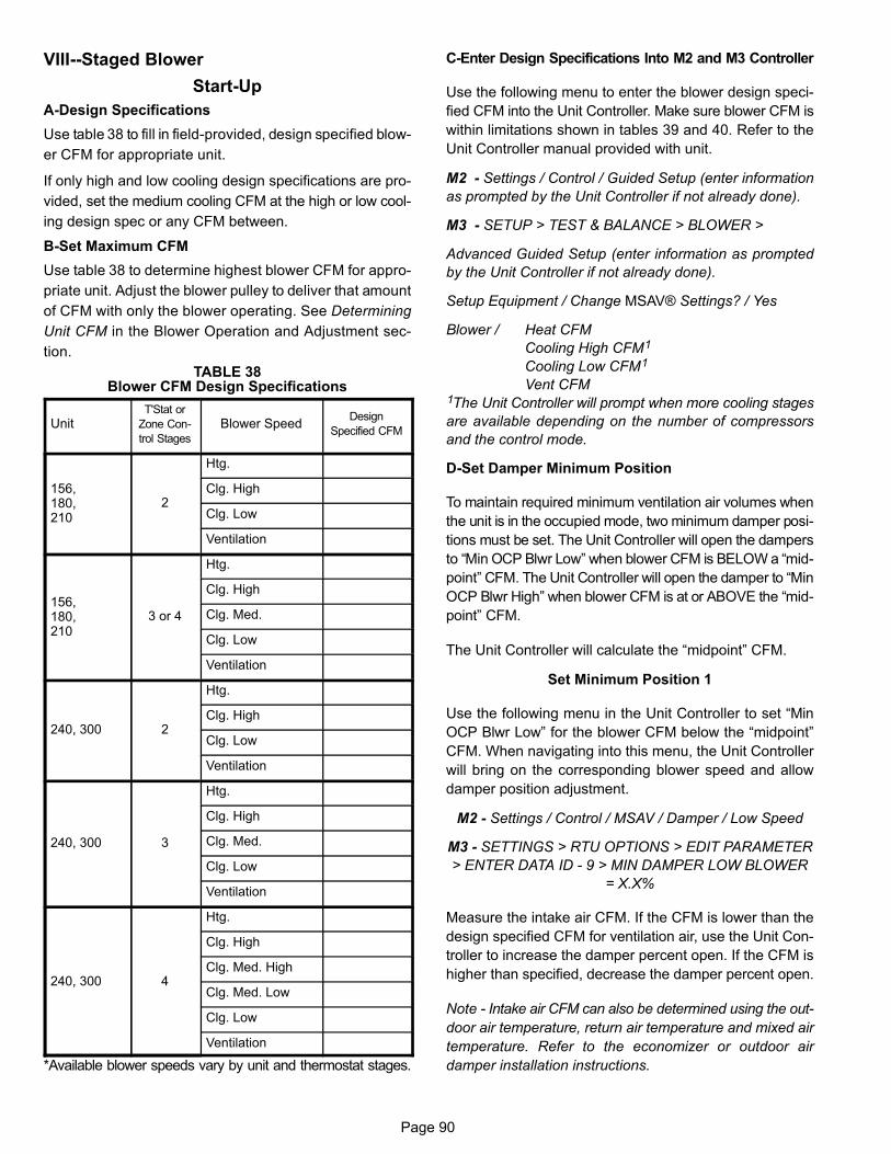
Page 90
VIII--Staged Blower
Start-Up
A-Design Specifications
Use table 38 to fill in field-provided, design specified blow
er CFM for appropriate unit.
If only high and low cooling design specifications are pro
vided, set the medium cooling CFM at the high or low cool
ing design spec or any CFM between.
B-Set Maximum CFM
Use table 38 to determine highest blower CFM for appro
priate unit. Adjust the blower pulley to deliver that amount
of CFM with only the blower operating. See Determining
Unit CFM in the Blower Operation and Adjustment sec
tion.
TABLE 38Blower CFM Design Specifications
UnitT'Stat or
Zone Con
trol Stages
Blower SpeedDesign
Specified CFM
156,180,210
2
Htg.
Clg. High
Clg. Low
Ventilation
156,180,210
3 or 4
Htg.
Clg. High
Clg. Med.
Clg. Low
Ventilation
240, 300 2
Htg.
Clg. High
Clg. Low
Ventilation
240, 300 3
Htg.
Clg. High
Clg. Med.
Clg. Low
Ventilation
240, 300 4
Htg.
Clg. High
Clg. Med. High
Clg. Med. Low
Clg. Low
Ventilation
*Available blower speeds vary by unit and thermostat stages.
C-Enter Design Specifications Into M2 and M3 Controller
Use the following menu to enter the blower design speci
fied CFM into the Unit Controller. Make sure blower CFM is
within limitations shown in tables 39 and 40. Refer to the
Unit Controller manual provided with unit.
M2 - Settings / Control / Guided Setup (enter information
as prompted by the Unit Controller if not already done).
M3 - SETUP > TEST & BALANCE > BLOWER >
Advanced Guided Setup (enter information as prompted
by the Unit Controller if not already done).
Setup Equipment / Change MSAV® Settings? / Yes
Blower / Heat CFM
Cooling High CFM1
Cooling Low CFM1
Vent CFM1The Unit Controller will prompt when more cooling stages
are available depending on the number of compressors
and the control mode.
D-Set Damper Minimum Position
To maintain required minimum ventilation air volumes when
the unit is in the occupied mode, two minimum damper posi
tions must be set. The Unit Controller will open the dampers
to “Min OCP Blwr Low” when blower CFM is BELOW a “mid
point” CFM. The Unit Controller will open the damper to “Min
OCP Blwr High” when blower CFM is at or ABOVE the “mid
point” CFM.
The Unit Controller will calculate the “midpoint” CFM.
Set Minimum Position 1
Use the following menu in the Unit Controller to set “Min
OCP Blwr Low” for the blower CFM below the “midpoint”
CFM. When navigating into this menu, the Unit Controller
will bring on the corresponding blower speed and allow
damper position adjustment.
M2 - Settings / Control / MSAV / Damper / Low Speed
M3 - SETTINGS > RTU OPTIONS > EDIT PARAMETER
> ENTER DATA ID - 9 > MIN DAMPER LOW BLOWER
= X.X%
Measure the intake air CFM. If the CFM is lower than the
design specified CFM for ventilation air, use the Unit Con
troller to increase the damper percent open. If the CFM is
higher than specified, decrease the damper percent open.
Note - Intake air CFM can also be determined using the out
door air temperature, return air temperature and mixed air
temperature. Refer to the economizer or outdoor air
damper installation instructions.

Page 91
Set Minimum Position 2
Use the same menu in the Unit Controller to set “Min OCP
Blwr High” for the blower CFM above the “midpoint” CFM.
When navigating into this menu, the Unit Controller will
bring on the corresponding blower speed and allow
damper position adjustment.
M2 - Settings / Control / MSAV / Damper / High Speed
M3 - SETTINGS > RTU OPTIONS > DAMPER > MIN
DAMPER POSITION BLOWR ON HIGH = X.X%
Measure the intake air CFM. If the CFM is lower than the
design specified CFM for ventilation air, use the Unit Con
troller to increase the damper percent open. If the CFM is
higher than specified, decrease the damper percent open.
Note - Intake air CFM can also be determined using the out
door air temperature, return air temperature and mixed air
temperature. Refer to the economizer or outdoor air
damper installation instructions.
E-VFD Bypass
M2 Controller
The supply air VFD is factory-set to by-pass the VFD manu
ally. To by-pass the VFD and operate the blower in the con
stant air volume mode, use the following Unit Controller
menu and set to “engaged”:
Settings / Control / MSAV / VFD Bypass
To configure the unit to by-pass the VFD automatically, use
the following Unit Controller menu and set to “automatic”:
Settings / Install / New M2 / MSAV VFD Bypass
Caution - Units not equipped with a VFD will be set to Set
tings / Control / MSAV VFD Bypass / None. The blower mo
tor could be damaged and/or result in product or property
damage if the setting is changed to automatic or manual.
M3 Controller
The supply air inverter is factory-set to by-pass the inverter
manually. To by-pass the inverter and operate the blower in
the constant air volume mode, use the following Unit Con
troller menu and set to “engaged”:
SETTINGS > RTU OPTIONS > BLOWER > VFD BY
PASS
To configure the unit to by-pass the inverter automatically,
use the following Unit Controller menu.
SETUP > INSTALL
Press SAVE until the menu reads:
CONFIGURATION ID 1
Change the 6th character position to A for automatic by
pass option.
Press SAVE
Caution - Units not equipped with an inverter will have the
6th character set to N, indicating the inverter is not by
passed. The blower motor could be damaged and/or result
in product or property damage if the setting is changed to
automatic or manual.

Page 92
TABLE 39MINIMUM AND MAXIMUM CFM
Gas Heat Minimum CFM
Unit Gas Heat Size Airflow CFM
LGH156-300S Low, Std. Med. 4500
LGH180-300S High 5125
Electric Heat Minimum CFM
Unit Heat Size (kW) Airflow CFM
LCH156 All 5200
LCH180-300S All 6000
Cooling Minimum CFM - 220 CFM/ton
Unit Blower Speed Airflow CFM
LGH/LCH156 Low, Med. Low, Med., Med. High 2860
LGH/LCH180 Low, Med. Low, Med., Med. High 3300
LGH/LCH210 Low, Med. Low, Med., Med. High 3850
LGH/LCH240 Low, Med. Low, Med., Med. High 4400
LGH/LCH300S Low, Med. Low, Med., Med. High 5500
Cooling Minimum CFM - 280 CFM/ton
Unit Blower Speed Airflow CFM
LGH/LCH156 High 3640
LGH/LCH180 High 4200
LGH/LCH210 High 4900
LGH/LCH240 High 5600
LGH/LCH300S High 7000
Smoke and Ventilation Minimum CFM - 150 CFM/ton
Unit Not Applicable Airflow CFM
LGH/LCH156 NA 1950
LGH/LCH180 NA 2250
LGH/LCH210 NA 2625
LGH/LCH240 NA 3000
LGH/LCH300S NA 3750
Heating and Cooling Maximum CFM - 480 CFM/ton
Unit Blower Speed Airflow CFM
LGH/LCH156 High 6240
LGH/LCH180 High 7200
LGH/LCH210 High 8400
LGH/LCH240 High 9600
LGH/LCH300S High 12000
TABLE 40MINIMUM AND MAXIMUM CFM - 180U, 240U, 300U
Gas Heat Minimum CFM
Unit Gas Heat Size Airflow CFM
LGH180U/240U/300U Low, Std., Med. 4500
LGH180U/240U/300U High 5125
Electric Heat Minimum CFM
Unit Heat Size (kW) Airflow CFM
LCH180U/240U/300U All 6000
Cooling 1 Minimum CFM - 130 CFM/ton
Unit Blower Speed Airflow CFM
LGH/LCH180U Low 1950
LGH/LCH240U Low 2600
LGH/LCH300U Low 3250
Cooling 2 Minimum CFM - 160 CFM/ton
Unit Blower Speed Airflow CFM
LGH/LCH180U Med. Low 2400
LGH/LCH240U Med. Low 3200
LGH/LCH300U Med. Low 4000
Cooling 3 Minimum CFM - 190 CFM/ton
Unit Blower Speed Airflow CFM
LGH/LCH180U High 2850
LGH/LCH240U High 3800
LGH/LCH300U High 4750
Cooling 4 Minimum CFM - 220 CFM/ton
Unit Blower Speed Airflow CFM
LGH/LCH180U High 3300
LGH/LCH240U High 4400
LGH/LCH300U High 5500
Smoke and Ventilation Minimum CFM - 150 CFM/ton
Unit Not Applicable Airflow CFM
LGH/LCH180U 2250
LGH/LCH240U 3000
LGH/LCH300U 3750
Heating and Cooling Maximum CFM - 480 CFM/ton
Unit Blower Speed Airflow CFM
LGH/LCH180U High 7200
LGH/LCH240U High 9600
LGH/LCH300U High 12000

Page 93
Operation
This is a summary of cooling operation.
Note - During a dehumidification demand the blower oper
ates at the highest speed. Free cooling is locked-out during
reheat operation. Refer to reheat start-up and operation
section for details.
A-Two-Stage T'Stat; 3- and 4-Compressor Units
1-Economizer With Outdoor Air Suitable
Y1 Demand -
Compressors Off
Blower Cooling Low
Dampers modulate
Y2 Demand -
Compressors Off
Blower Cooling High
Dampers Modulate
156, 180H, 210, 240H, 300S - If dampers are at maximum
open for three minutes, compressor 1 and 2 are energized
and blower stays on cooling high.
180U, 240U, 300U - If dampers are at maximum open for
three minutes, two compressors (one from each circuit) are
energized and blower stays on cooling high.
2-No Economizer or Outdoor Air Not Suitable
Y1 Demand -
First-stage Compressors On
Blower Cooling Low
Dampers Minimum Position
Y2 Demand -
All Compressors On
Blower Cooling High
Dampers Minimum Position
B-Three-Stage T'Stat, 3 and 4 Compressor Units AND
Zone Sensor (4 Clg. Stages), 3-Compressor Units
1-Economizer With Outdoor Air Suitable
Three-Compressor Units:
Y1 Demand -
Compressors Off
Blower Cooling Low
Dampers Modulate
Y2 Demand -
Compressors Off
Blower Cooling High
Dampers Modulate
Note - If dampers are at maximum open for three minutes,
compressor 1 is energized and blower stays on cooling high.
Y3 Demand -
Compressors 1 and 2 On
Blower Cooling High
Dampers Maximum Open
Y4 Demand -
All Compressors On
Blower Cooling High
Dampers Maximum Open
Four-Compressor Units:
Y1 Demand -
Compressors Off
Blower Cooling Low
Dampers modulate
Y2 Demand -
Compressors Off
Blower Cooling High
Dampers Modulate
156, 180H, 210, 240H, 300S - If dampers are at maximum
open for three minutes, compressors 1 and 2 are energized
and blower stays on cooling high.
180U, 240U, 300U - If dampers are at maximum open for
three minutes, two compressors (one from each circuit) are
energized and blower stays on cooling high.
Y3 Demand -
Compressors 1, 2 and 3 On
(180U, 240U, 300U any three compressors are on
Blower Cooling High
Dampers Maximum Open
2-No Economizer or Outdoor Air Not Suitable
Three-Compressor Units:
Y1 Demand -
Compressor 1 On
Blower Cooling Low
Y2 Demand -
Compressors 1 and 2 On
Blower Cooling Medium
Y3 or Y4 Demand -
All Compressors On
Blower Cooling High
Four-Compressor Units:
Y1 Demand -
Compressors 1 and 2 On
180U, 240U, 300U - Two Compressors On
(one from each circuit)
Blower Cooling Low
Y2 Demand -
Compressors 1, 2 and 3 On
180U, 240U, 300U any three compressors are On
Blower Cooling Medium
Y3 Demand -
All Compressors On
Blower Cooling High
C-Zone Sensor (4 Clg. Stages), 4-Compressor Units
1-Economizer With Outdoor Air Suitable
Y1 Demand -
Compressors Off
Blower Cooling Low
Dampers modulate
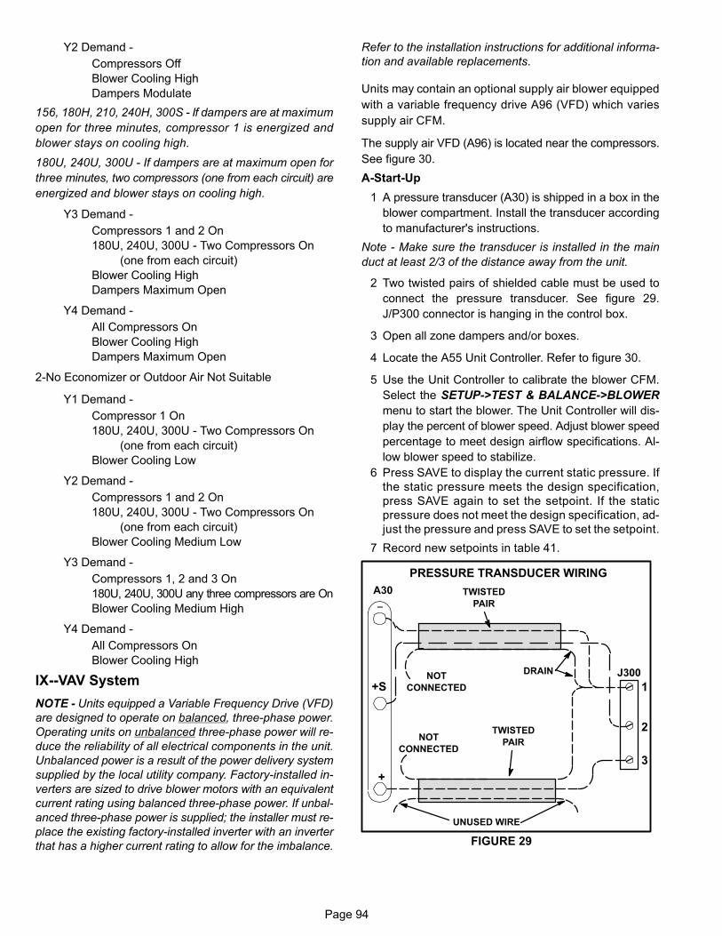
Page 94
Y2 Demand -
Compressors Off
Blower Cooling High
Dampers Modulate
156, 180H, 210, 240H, 300S - If dampers are at maximum
open for three minutes, compressor 1 is energized and
blower stays on cooling high.
180U, 240U, 300U - If dampers are at maximum open for
three minutes, two compressors (one from each circuit) are
energized and blower stays on cooling high.
Y3 Demand -
Compressors 1 and 2 On
180U, 240U, 300U - Two Compressors On
(one from each circuit)
Blower Cooling High
Dampers Maximum Open
Y4 Demand -
All Compressors On
Blower Cooling High
Dampers Maximum Open
2-No Economizer or Outdoor Air Not Suitable
Y1 Demand -
Compressor 1 On
180U, 240U, 300U - Two Compressors On
(one from each circuit)
Blower Cooling Low
Y2 Demand -
Compressors 1 and 2 On
180U, 240U, 300U - Two Compressors On
(one from each circuit)
Blower Cooling Medium Low
Y3 Demand -
Compressors 1, 2 and 3 On
180U, 240U, 300U any three compressors are On
Blower Cooling Medium High
Y4 Demand -
All Compressors On
Blower Cooling High
IX--VAV System
NOTE - Units equipped a Variable Frequency Drive (VFD)
are designed to operate on balanced, three-phase power.
Operating units on unbalanced three-phase power will re
duce the reliability of all electrical components in the unit.
Unbalanced power is a result of the power delivery system
supplied by the local utility company. Factory-installed in
verters are sized to drive blower motors with an equivalent
current rating using balanced three-phase power. If unbal
anced three-phase power is supplied; the installer must re
place the existing factory-installed inverter with an inverter
that has a higher current rating to allow for the imbalance.
Refer to the installation instructions for additional informa
tion and available replacements.
Units may contain an optional supply air blower equipped
with a variable frequency drive A96 (VFD) which varies
supply air CFM.
The supply air VFD (A96) is located near the compressors.
See figure 30.
A-Start-Up
1 A pressure transducer (A30) is shipped in a box in the
blower compartment. Install the transducer according
to manufacturer's instructions.
Note - Make sure the transducer is installed in the main
duct at least 2/3 of the distance away from the unit.
2 Two twisted pairs of shielded cable must be used to
connect the pressure transducer. See figure 29.
J/P300 connector is hanging in the control box.
3 Open all zone dampers and/or boxes.
4 Locate the A55 Unit Controller. Refer to figure 30.
5 Use the Unit Controller to calibrate the blower CFM.
Select the SETUP->TEST & BALANCE->BLOWER
menu to start the blower. The Unit Controller will dis
play the percent of blower speed. Adjust blower speed
percentage to meet design airflow specifications. Al
low blower speed to stabilize.
6 Press SAVE to display the current static pressure. If
the static pressure meets the design specification,
press SAVE again to set the setpoint. If the static
pressure does not meet the design specification, ad
just the pressure and press SAVE to set the setpoint.
7 Record new setpoints in table 41.
PRESSURE TRANSDUCER WIRING
TWISTED
PAIR
UNUSED WIRE
DRAINNOT
CONNECTED
NOT
CONNECTED
TWISTED
PAIR
FIGURE 29
A30
+S
_
+
J300
1
2
3

Page 95
FIGURE 30
SUPPLY AIR VARIABLE FREQUENCY DRIVE
A55 UNITCONTROLLER
A96SUPPLY AIR
VFD
DETAIL A
P300
J300
24V
P267
Note - The Unit Controller will lock-out the unit for 5 minutes
if static pressure exceeds 2.0”w.c. for 20 seconds. The
Unit Controller will permanently shut down the unit after
three occurrences. See Unit Controller parameters 110,
42, and 43 to adjust default values.
8 If the desired CFM cannot be met with current pulley
setup, refer to the Blower Operation and Adjustments
section to adjust CFM.
B-Unit Operation
Use the Unit Controller to check unit mechanical operation.
See the Service - Test section of the Unit Controller manu
al.
TABLE 41RECORD ADJUSTED SETPOINTS
ParameterSetpoint
DescriptionSetpoint
“w.c.DisplaySetting
386 Smoke
387 Ventilation
388 Heating
389 Cooling
C-Supply Air VFD Bypass (Optional)
IMPORTANT - All dampers must be open to prevent dam
age to duct work and dampers.
1 Turn off all power to unit.
2 Locate J/P247 and J/P248 connectors near the VFD.
See figure 31.
3 Disconnect P247 from J247 and connect J249 to
P247. See figure 32.
4 Disconnect J248 from P248 and connect connect
P248 jumper plug to J248. P248 jumper plug is at
tached to the J248 wire harness near the J248 jack
connector. See figure 33.
5 Locate VFD control relay K203 on the lower control
panel next to terminal strip TB24. See figure 31.
6 Locate wires labeled K203-A and K203-B in area
shown in figure 31. Disconnect insulated terminals.
7 Locate wires labeled K3-A and K3-B coming from K3
blower relay. Connect to K203-A to K3-A and K203-B
to K3-B.
8 Restore power to unit. Blower will operate in constant
air volume (CAV) mode.
9 Check the indoor blower motor nameplate for full load
amperage (FLA) value. Measure the amp readings
from the indoor blower motor operating in bypass
mode. If measured amps are higher than nameplate
FLA value, decrease the CFM by opening (turning
counterclockwise) the motor pulley. See figure 10. Do
not exceed minimum and maximum number of pulley
turns as shown in table 5.
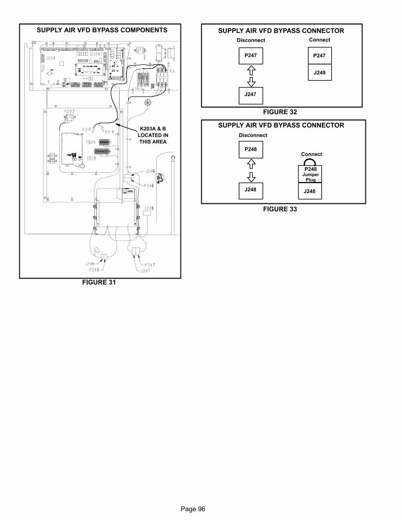
Page 96
FIGURE 31
SUPPLY AIR VFD BYPASS COMPONENTS
K203A & B
LOCATED IN
THIS AREA
J249
FIGURE 32
SUPPLY AIR VFD BYPASS CONNECTOR
P247
J247
P247
Disconnect Connect
P248Jumper
Plug
J248
FIGURE 33
SUPPLY AIR VFD BYPASS CONNECTOR
P248
J248
Disconnect
Connect

Page 97
X-Wiring Diagrams and Sequence of Operation
LCH156 UNIT DIAGRAM
1
11
10
12
15
1
12
35
6
8
9
4
14

Page 98
LCH156 DIAGRAM KEY DESCRIPTION
J/P JACK/PLUG DESCRIPTIONKEY COMPONENTA55 PANEL, MAIN BOARD LENNOX
B1 COMPRESSOR 1
B2 COMPRESSOR 2
B3 MOTOR, BLOWER
B4 MOTOR, OUTDOOR FAN 1
B5 MOTOR, OUTDOOR FAN 2
B10 MOTOR, EXHAUST FAN 1
B11 MOTOR, EXHAUST FAN 2
B13 COMPRESSOR 3
B21 MOTOR, OUTDOOR FAN 3
C1 CAPACITOR, OUTDOOR FAN 1
C2 CAPACITOR, OUTDOOR FAN 2
C6 CAPACITOR, EXHAUST FAN 1
C8 CAPACITOR, EXHAUST FAN 2
CB10 CIRCUIT BREAKER, MAIN DISCONNECT UNIT
C18 CAPACITOR, OUTDOOR FAN 3
CB8 CIRCUIT, BREAKER T1
CB18 CIRCUIT, BREAKER T18
F30 FUSE, TRANSFORMER T29 PRIMARY
F31 FUSE, TRANSFORMER T29 SECONDARY
HR1 HEATER COMPRESSOR 1
HR2 HEATER COMPRESSOR 2
HR5 HEATER COMPRESSOR 3
J11 JACK, GFI, RECEPTACLE
CONTACTOR, COMPRESSOR 1CONTACTOR, COMPRESSOR 2
CONTACTOR, BLOWER
RELAY, OUTDOOR FAN 1CONTACTOR, COMPRESSOR 3
K65�1,2 RELAY, EXHAUST FAN
F4 FUSE, MAIN UNIT
F6 FUSE, EXHAUST FAN
A178 PANEL, COMP 3 & 4 AND 2ND STAGE HEAT � C3
F10 FUSE, OUTDOOR FAN MOTOR
F61 FUSE, UNIT SCCR OPTION

Page 99
LCH180 UNIT DIAGRAM
1
11
10
12
15
1
1 2
3
5
6
8
9
4
14

Page 100
LCH180 KEY DESCRIPTION

Page 101
LCH210 UNIT DIAGRAM
10
1
11
12
15
1
2
3
4
5
6
8
9
4
14
1
11

Page 102
LCH210 KEY DESCRIPTION
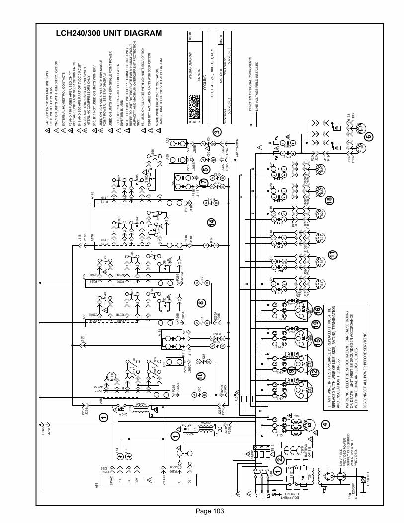
Page 103
LCH240/300 UNIT DIAGRAM
10
18
1
11
15
1
2
3
5
6
8
9
4
14
1
16
19
17
12
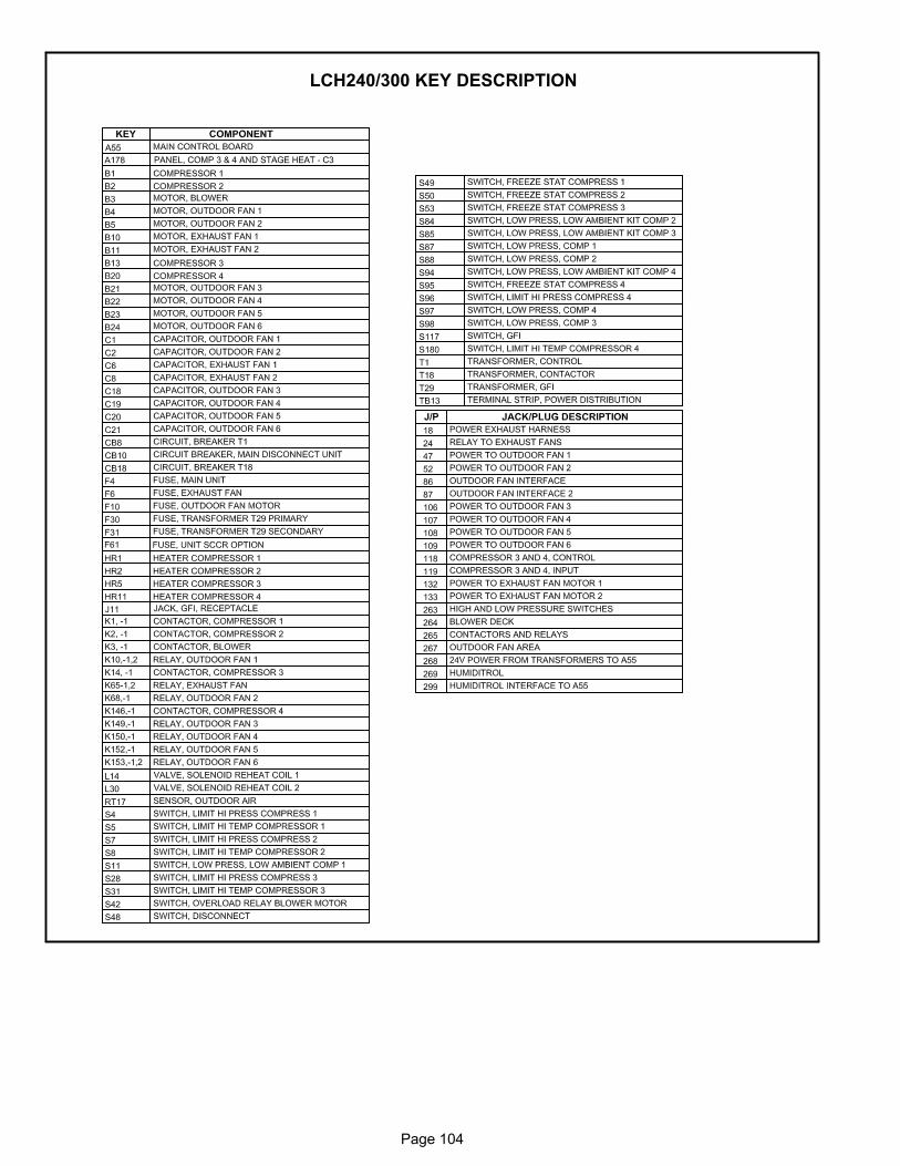
Page 104
LCH240/300 KEY DESCRIPTION

Page 105
Sequence of Operation 156H / 300S
POWER:
1. Line voltage from TB2, unit disconnect S48, or other
factory or field installed optional power disconnects,
such as CB10, energizes transformer T1 and T18.
Transformer T1 provides 24VAC power to the A55 Unit
Controller and T18 provides 24VAC power to A59
Compressor 3 and 4 Controller. The two controllers
provide 24VAC power to the unit cooling, heating and
blower controls and thermostat.
2. Terminal block TB13 is also energized when the unit dis
connect closes. TB13 supplies line voltage to com
pressor crankcase heaters, compressors, blower
motors and fan motors.
BLOWER OPERATION (OCP INPUT MUST BE ON):
3. The A55 Unit Controller receives a demand from thermo
stat terminal G. A55 energizes blower contactor K3 with
24VAC.
4. N.O. K3‐1 closes, energizing blower B3.
ECONOMIZER OPERATION:
5. The A55 Unit Controller receives a demand and energizes
exhaust fan relay K65 with 24VAC at 50% (travel) out
side air damper open (adjustable).
6. N.O. K65‐1 and K65‐2 both close, energizing exhaust
fan motors B10 and B11.
1ST STAGE COOLING (BOTH COMPRESSORS B1 AND
B2 ARE ENERGIZED):
7. First stage cooling demand energizes Y1 and G in the
thermostat. G energizes blower, if blower is not already
running (see step 3).
8. 24VAC is routed to the A55 Unit Controller. After A55 proves
N.C. low pressure switch S87 and S88, N.C. freezestat S49
and S50 and N.C. high pressure switch S4 and S7, com
pressor contactors K1 and K2 are energized.
9. N.O. contacts K1-1 and K2-1 close energizing compressor
B1 and B2.
10. A55 Unit Controller and A59 Compressor 3 and 4 Con
troller energize fan contactor K10 (all units), K68 (all units),
K149 (180H-300S only), K150 (180/210H only), K152
(210H only), K153 (210H only) based on low ambient
switch S11 and S84 inputs and predefined control logic.
11. N.O. contact K10-1 (all units), K68-1 (all units), K149-1
(180H-300S only), K150-1 (180H/210H only), K152-1
(210H only), K153-1 (210H only) close energizing fan B4
(all units), B5 (all units), B21 (all units), B22 (180H/210H on
ly), B23 (210H only), B24 (210H only).
12. Relay contacts K10-1 (210H), K10-2 (156H, 240H, 300S) or
K68-1 (180H) open de-energizing compressor 1, 2 and 3
crankcase heater HR1 (all units), HR2 (all units) and HR5
(156H-210H only).
2ND STAGE COOLING (B13 IN 156H-210H AND BOTH
B13 AND B20 IN 240H AND 300S ARE ENERGIZED):
13. Second stage cooling demand energizes Y2.
14.24VAC is routed to A59 Compressor 3 and 4 Con
troller. After A59 proves N.C. low pressure switches
S98 and S97, N.C. freezestats S53 and S95 and N.C.
high pressure switches S28 and S96, compressor
contactors K14 and K146 are energized.
NOTE: LCH156-210 units will be equipped with S98, S53,
S28 and K14 only.
15. N.O. contacts K14-1 close energizing compressor B13.
16. N.O. contacts K146-1 close energizing compressor B20
(LCH240/300 only).
17. A59 Compressor 3 and 4 Controller energizes fan contac
tor K150, K152, K153 (240H/300S only) based on low am
bient switch S85 and S94 inputs and predefined Controller
logic.
18.N.O. contacts K150-1, K152-1 and K153-1
(240H/300S only) close energizing condenser fan
B22, B23 and B24 (240H/300S only).
19.N.C. contacts K153-2 (240H/300S only) open de-en
ergizing compressor 3 and 4 crankcase heater HR5
and HR11 (240/300S only).

Page 106
LCH180U/240U/300UUNIT DIAGRAM
1
1
2
4
5
7
8
99
10
10
11
13
14
15
16

Page 107
LCH180U/240U/300U KEY DESCRIPTION

Page 108
Sequence of Operation LCH180U/240U/300U
POWER:
1. Line voltage from TB2, unit disconnect S48, or other
factory or field installed optional power disconnects,
such as CB10, energizes transformer T1 and T18.
Transformer T1 provides 24VAC power to the A55 Unit
Controller and T18 provides 24VAC power to A59
Compressor 3 and 4 Controller. The two controllers
provide 24VAC power to the unit cooling, heating and
blower controls and thermostat.
2. Terminal block TB13 is also energized when the unit dis
connect closes. TB13 supplies line voltage to com
pressor crankcase heaters, compressors, blower
motors and fan motors.
BLOWER OPERATION (OCP INPUT MUST BE ON):
3. See Staged No Bypass and Staged With Bypass next 2
pages.
ECONOMIZER OPERATION:
4. The A55 Unit Controller receives a demand and energizes
exhaust fan relay K65 and K231 with 24VAC at 50%
(travel) outside air damper open (adjustable).
5. N.O. K65‐1, K65‐2, K231-01 and K231-02 close, en
ergizing exhaust fan motors B10 and B11.
1ST STAGE COOLING
6. First stage cooling demand energizes Y1 and G in the
thermostat. G energizes blower, if blower is not already
running (see step 3).
7. 24VAC is routed to the A55 Unit Controller. After A55 proves
N.C. low pressure switch S87, N.C. freezestat S49, and
N.C. high pressure switch S4, high temperature limits S5
and S8, compressor contactors K1 and K2 are energized.
8. N.O. contacts K1-1 and K2-1 close energizing compressor
B1 and B2.
9. A55 Unit Controller and A178 Compressor 3 and 4 Con
troller energize fan transformers T5 and T59 based on low
ambient switch S11 and S85 inputs and predefined control
logic.
10. Transformer T5 energized outdoor fans B4, B5 and B21.
Transformer T59 energizes outdoor fan B22, B23 and B24.
11. Relay contacts K191-2, K194-2 open de-energizing com
pressor 1 and 2 crankcase heater HR1 and HR2.
2ND STAGE COOLING
12. Second stage cooling demand energizes Y2.
13.24VAC is routed to A178 Compressor 3 and 4 Con
troller. After A178 proves N.C. low pressure switch S98,
N.C. freezestat S53, and N.C. high pressure switch S28,
hight temperature limits S31 and S180, compressor con
tactors K14 and K146 are energized
14. N.O. contacts K14-1 close energizing compressor B13.
15. N.O. contacts K146-1 close energizing compressor B20.
16.N.C. contacts K233-2 and K234-01 open de-energiz
ing compressor 3 and 4 crankcase heater HR5 and
HR11.

Page 109
Staged-Blower UNITS - NO BYPASS
OPERATION:
1 A55 energizes the K203 relay coil.
2 K203-2 N.O. contacts close to start A96 forward
rotation signal STF.
3 A133 controls the second stage power exhaust
relay K231 coil through pin #5. K231-1 and -2
N.O. contacts will close to start the second power
exhaust fan when A133 energizes the K231 coil.
4 Blower B3 speed is controlled by a 0-10VDC sig
nal from A133 AO1 to A96 terminal 2.
5 A96 status is monitored by A133 through N.C.
contacts B-C on A96.
New Form No.Supersedes
WIRING DIAGRAM
MSAV/ VAV BLOWER - NO BYPASS
02/19
COOLING
SECTION B3��������REV. 1
537718-02
24V POWER
537718-03
L1
L2
L3
B10
F6
F6
TB13
K65
A
B
A55
P265
J265EJ265B
P265
J265E
K231
A
B
24V COMMON
K203-2
9
6
STF
SD
K203
AB
2
A96
5
J246
P246
J247
P247
B3
C
B
J248
P248 P248
J248
B11
C8
P133
J133
K231-2
9
6
F6 FUSES ARE USED ON 240/300Y�VOLT UNITS WITH FACTORYINSTALLED POWER EXHAUST
F6 FUSES ARE USED ON ALLY�VOLT UNITS WITH FIELDINSTALLED POWER EXHAUST
P248
KEY COMPONENT
A55 PANEL, MAIN CONTROL
A96 CONTROL, INVERTER
A133 CONTROL, GENERAL PURPOSE
B3 MOTOR, BLOWER
B10 MOTOR, EXHAUST FAN 1
B11 MOTOR, EXHAUST FAN 2
C6 CAPACITOR, EXHAUST FAN 1
C8 CAPACITOR, EXHAUST FAN 2
F4 FUSE, MAIN UNIT
18 POWER EXHAUST HARNESS
24 POWER, RELAY TO EXHAUST FANS
132 POWER TO EXHAUST FAN MOTOR 1
133 POWER TO EXHAUST FAN MOTOR 2
246 POWER TO VFD
247 POWER, VFD TO MTR
265 A55 TO CONTACTORS AND RELAYS
K65 RELAY, EXHAUST FAN
K203 RELAY, INVERTER START FWD ROTATION
S48 SWITCH, DISCONNECT
TB13 TERMINAL STRIP, POWER DISTRIBUTION
248 VFD CONTROL
J/P JACK/PLUG DESCRIPTION
K231 RELAY, EXHAUST FAN 2
J248
J259
(ODF)PWM 2
(ODF)PWM 3
COM
(IDB)PWM 1/VO
RELAY
COM
FB
20V
A55
K65-2
9
6
K65-1
7
4
K231-1
7
4
PCR55
300 DUCT STATIC PRESSURE
267 A30 INPUT
R55 RESISTOR,VFD LOADING, A96
A55
GND
0-10 VDC IN
P267
J267
� +S +
A30 SENSOR, DUCT STATIC PRESSURE
A30SETRA
DENOTES OPTIONALCOMPONENTS
DENOTES FIELDINSTALLED WIRING
RST
WVU
G
G
A96
F4/F61
F4 USED ON LCH UNITS.F61 USED ON LGH UNITS WITH SCCROPTION
F6 FUSE, EXHAUST FAN
F61 FUSE, UNIT SCCR OPTION

Page 110
MSAV UNITS - WITH BYPASS
1 A55 energizes K202 and K203 relay coils.
2 K203-1 N.O. contacts close and K203-3 N.C.
contacts open to allow A133 to control the sec
ond stage power exhaust relay K231 coil through
pin #5. K231-1 and -2 N.O. contacts will close to
start the second power exhaust fan B11 when
A133 energizes K231 coil.
3 K203-1 N.C. contacts open to de-energize K3
relay coil. K3 contacts open to interrupt power to
B3 blower motor through K3 N.O. relay contacts.
4 K202 contacts close to allow power to B3 blower mo
tor from A96.
5 K203-2 N.O. contacts close to start A96 forward rota
tion signal STF.
6 Blower B3 speed is controlled by a 0-10VDC signal
from A133 AO1 to A96 terminal 2.
7 A96 status is monitored by A133 through N.C. con
tacts B-C on A96.
COOLING
REV. 0
S42 USED ON M−VOLT UNITS AND UNITS WITHHIGH EFFICIENCY MOTORS AND MOTORSLESS INTERNAL OVERLOAD PROTECTION
S48
B11
C8
F6
F6
P133
J133
TB13
F6 FUSES ARE USED ON 240/300 Y−VOLTUNITS WITH FACTORY INSTALLEDPOWER EXHAUST
F6 FUSES ARE USED ON ALL Y−VOLTUNITS WITH FIELD INSTALLED POWEREXHAUST
R S T
WVU
G
G
A96
J246
P246
J247
K3
K231-1
7
4
K231-2
9
6
S42
K202
J249
P247
B3
P24
J24
P18
J18
KEY COMPONENTA55 PANEL, MAIN CONTROL
A96 CONTROL, INVERTER
A133 CONTROL, GENERAL PURPOSE
B3 MOTOR, BLOWER
B10 MOTOR, EXHAUST FAN 1
B11 MOTOR, EXHAUST FAN 2
C6 CAPACITOR, EXHAUST FAN 1
C8 CAPACITOR, EXHAUST FAN 2
F6 FUSE, EXHAUST FAN
18 POWER EXHAUST HARNESS24 POWER, RELAY TO EXHAUST FANS
132 POWER TO EXHAUST FAN MOTOR 1133 POWER TO EXHAUST FAN MOTOR 2194 GP CONTROL INPUT, OUTPUT
246 POWER TO VFD247 POWER, VFD TO MTR
265 A55 TO CONTACTORS & RELAYS
K65 RELAY, EXHAUST FAN
K203 RELAY, INVERTER START FWD ROTATION
S48 SWITCH, DISCONNECT
TB13 TERMINAL STRIP, POWER DISTRIBUTION
248 VFD CONTROL
J/P JACK/PLUG DESCRIPTION
K202 CONTACTOR, VFD POWER TO MOTOR
K231 RELAY, EXHAUST FAN 2
K3 CONTACTOR, BLOWER
249 POWER, CONTACTOR BYPASSK65
A
B
P265
J265E
K231
A
B
24V COMMON
K203-29
6
STF
SD
K203AB
2
A96
5
C
B
J248
J248
K202AB
K3
A
B
P248J248
K203-382
P248
J248
S42 SWITCH, OVERLOAD RELAY BLWR MOTOR
J259
(ODF)PWM 2
(ODF)PWM 3
COM
(IDB)PWM 1/VO
RELAY
COM
FB
20V
A55
K65-1
7
4
K65-2
9
6
PC
R55 RESISTOR, VFD LOADING, A96

Page 111
ELECTRIC HEAT DIAGRAM
11
5
8
17
13
6
3
16
10
Lennox Commercial
HEATING
NOT USED ON 15 AND 30KW UNITS
TB3 IS USED IN SOME UNITS
KW HE1 HE2 HE3 HE4 HE5 HE6 HE7 HE8 HE9 HE10 HE11
45 15 15 15
60 15 15 15 15
15 7.5 7.5
30 15 15
90 15 15 15 15 15 15
DESIGNATION VOLTAGE
Y 208−230/60/3
G 460/60/3
J 575/60/3
M 380−420/50/3
B UNITS 090 TO 150
K15−1
K15−1
K15−1
K16−1
K16−1
K16−1
K17−1
K17−1
K17−1
K18−1
K18−1
K18−1
B
KW HE1 HE12 HE13 HE14
45 15 7.5 15 7.5
60 15 15 15 15
C − D
REMOVEJUMPER PLUG WHEN FIELD INSTALLINGELECTRIC HEAT S15 USED IN 90 TO 150 UNITS
DESCRIPTION
KEY DESCRIPTION
A55 PANEL, MAIN
F3 FUSE, ELECTRIC HEAT 1
F4 FUSE, UNIT
F42 FUSE, ELECTRIC HEAT 2
F43 FUSE, ELECTRIC HEAT 3
F44 FUSE, ELECTRIC HEAT 4
F45 FUSE, ELECTRIC HEAT 5
F46 FUSE, ELECTRIC HEAT 6
F49 FUSE, ELECTRIC HEAT 7
F50 FUSE, ELECTRIC HEAT 8
HE1 ELEMENT, ELECTRIC HEAT 1
HE2 ELEMENT, ELECTRIC HEAT 2
HE3 ELEMENT, ELECTRIC HEAT 3
HE4 ELEMENT, ELECTRIC HEAT 4
HE5 ELEMENT, ELECTRIC HEAT 5
HE6 ELEMENT, ELECTRIC HEAT 6
HE7 ELEMENT, ELECTRIC HEAT 7
HE8 ELEMENT, ELECTRIC HEAT 8
HE9 ELEMENT, ELECTRIC HEAT 9
HE10 ELEMENT, ELECTRIC HEAT 10
HE11 ELEMENT, ELECTRIC HEAT 11
HE12 ELEMENT, ELECTRIC HEAT 12
HE13 ELEMENT, ELECTRIC HEAT 13
HE14 ELEMENT, ELECTRIC HEAT 14
J7 JACK, ELECTRIC HEAT SUB−BASE KIT
J37 JACK, ELECTRIC HEAT LIMIT
J271 JACK, HEATING SENSORS 1
J272 JACK, HEATING SENSORS 2
J265C JACK, CONTACTOR RELAY
J266 JACK, HEATING CONTROL
K9,−1 RELAY, HEATING
K15,−1 CONTACTOR, ELECTRIC HEAT 1,2
K16,−1 CONTACTOR, ELECTRIC HEAT 1A,2A
K17,−1 CONTACTOR, ELECTRIC HEAT 3,4
K18,−1 CONTACTOR, ELECTRIC HEAT 5,6
P7 PLUG, ELECTRIC HEAT SUB−BASE KIT
P37 PLUG, ELECTRIC HEAT LIMIT
P271 PLUG, HEATING SENSORS 1
P272 PLUG, HEATING SENSORS 2
P265 PLUG, CONTACTOR RELAY
P266 PLUG, HEATING CONTROL
S15 SWITCH, LIMIT PRIMARY ELECTRIC HEAT
S19 THERMOSTAT, ELECTRIC HEAT LIMIT
S20 SWITCH, LIMIT SECONDARY ELECTRIC HEAT 1
S107 SWITCH, PRIMARY ELECTRIC HEAT
S157 SWITCH, LIMIT SECONDARY ELECTRIC HEAT 2
S158 SWITCH, LIMIT SECONDARY ELECTRIC HEAT 3
S159 SWITCH, LIMIT SECONDARY ELECTRIC HEAT 4
S160 SWITCH, LIMIT SECONDARY ELECTRIC HEAT 5
S161 SWITCH, LIMIT SECONDARY ELECTRIC HEAT 6
S171 SWITCH, LIMIT SECONDARY ELECTRIC HEAT 7
S172 SWITCH, LIMIT SECONDARY ELECTRIC HEAT 8
TB2 TERMINAL STRIP, UNIT
TB3 TERMINAL STRIP, ELECTRIC HEAT
TB2, CB10 OR S48 MAY BE USED
T18 USED ON HEAT PUMP UNITS
H2
S100−NC
S69
S99 − NC
S99 − NO
S100 − C
S69
S45
GV3
S45
H2
S19
S15
S19 IS USED ON HEAT PUMP 90 THROUGH 150 UNITSONLY.
3
4
16
13
14
9
17 14

Page 112
ELECTRIC HEAT DIAGRAM
Lennox Commercial
HEATING
NOT USED ON 15 AND 30KW UNITS
TB3 IS USED IN SOME UNITS
S15 IS USED ON B UNITS 90 TO 150
REMOVE JUMPER PLUG WHEN FIELDINSTALLING ELECTRIC HEAT
TB2, S48 OR CB10 MAY BE USED
KW HE1 HE2 H1A H2A HE3 HE4 HE5 HE6 HE7 HE8
45 15 15 15
60 15 15 15 15
15 7.5 7.5
30 15 15
45 15 7.5 15 7.5
60 15 15 15 15
90 15 15 15 15 15 15
120 15 15 15 15 15 15 15 15
DESCRIPTION
KEY DESCRIPTION
A55 CONTROL, BOARD LENNOX
F3 FUSE, ELECTRIC HEAT
F4 FUSE, UNIT
F42 FUSE, ELECTRIC HEAT 1 A, 2A
F43 FUSE, ELECTRIC HEAT 3, 4
F44 FUSE, ELECTRIC HEAT 5
F45 FUSE, ELECTRIC HEAT 6, 7
HE1 ELEMENT, ELECTRIC HEAT 1
HE2 ELEMENT, ELECTRIC HEAT 2
HE3 ELEMENT, ELECTRIC HEAT 3
HE4 ELEMENT, ELECTRIC HEAT 4
HE5 ELEMENT, ELECTRIC HEAT 5
HE6 ELEMENT, ELECTRIC HEAT 6
HE7 ELEMENT, ELECTRIC HEAT 7
HE8 ELEMENT, ELECTRIC HEAT 8
J7 JACK, ELECTRIC HEAT SUB−BASE KIT
J37 JACK, ELECTRIC HEAT LIMIT
J265 JACK, CONTACTOR RELAY
J266 JACK, HEATING CONTROL
J271 JACK, HEATING SENSORS STG 1
J272 JACK, HEATING SENSORS STG 2
K9,−1 RELAY, HEAT
K15,−1 CONTACTOR, ELECTRIC HEAT 1,2
K16,−1 CONTACTOR, ELECTRIC HEAT 1A,2A
K17,−1 CONTACTOR, ELECTRIC HEAT 3,4
K18,−1 CONTACTOR, ELECTRIC HEAT 5,6
P7 PLUG, ELECTRIC HEAT SUB−BASE KIT
P37 PLUG, ELECTRIC HEAT LIMIT
P265 PLUG, CONTACTOR RELAY
P266 PLUG, HEATING CONTROL
P271 PLUG, HEATING SENSORS STG 1
P272 PLUG, HEATING SENSORS STG 2
S15 SWITCH, LIMIT PRIMARY ELECTRIC HEAT
S19 THERMOSTAT, ELECTRIC HEAT LIMIT
S20 SWITCH, LIMIT SECONDARY ELECTRIC HEAT 1,2
S107 SWITCH, PRIMARY ELECTRIC HEAT
S157 SWITCH, LIMIT SECONDARY ELECTRIC HEAT 1A
S158 SWITCH, LIMIT SECONDARY ELECTRIC HEAT 2A
S159 SWITCH, LIMIT SECONDARY ELECTRIC HEAT 3,4
S160 SWITCH, LIMIT SECONDARY ELECTRIC HEAT 5,6
TB2 TERMINAL STRIP, UNIT
TB3 TERMINAL STRIP, ELECTRIC HEAT
T18 USED ON HEAT PUMP UNITS
H2 H2
S100−NC
S69
S99 − NC
S99 − NO
S100 − C
S69
S45
GV3
S45
S19
S15
S19 IS USED ON HEAT PUMP 090THROUGH 150 UNITS ONLY.
DESIGNATION VOLTAGE
G 460/60/3
J 575/60/3
5
8 13
3
16
10
3 16
13
11
17
4
14
14
9
6
17

Page 113
SEQUENCE OF OPERATIONEHA-15, 30, 45, 60, 90 - Y
EHA-15, 30, 45, 60, 90 - G, J and M
The Y voltage diagram use elements configured
in a Wye. The G and J voltage diagram use ele
ments configured in a Delta. Both diagrams follow
the following sequence of operation:
NOTE:Two electric heat sections are used in all 15kW
through 90kW heaters. The heat sections are la
belled first electric heat section (left side) and
second electric heat section (right side). See fig
ure 16.
NOTE: In the case of EHA 15 and 30kW, the second
heat section (right side) is a slave (only has elec
tric heat elements and a limit). Line voltage is sup
plied to elements in both heat section one (left
side) and two (right side) by the contactors in heat
section one (left side).
HEATING ELEMENTS:
1 Terminal strip TB3 is energized when the unit dis
connect closes. TB3 supplies line voltage to elec
tric heat elements HE1 through HE14. Each heat
ing element is protected by fuse F3.
FIRST STAGE HEAT:
2 Heating demand initiates at W1 in thermostat.
3 24VAC is routed to the main control module A55.
After A55 proves N.C. primary limits S15 (heat
section one, left side), S107 (heat section two,
right side), the electric heat contactor K15 and
heat relay K9 are energized.
4 N.O. contact K15‐1 closes allowing the first bank
of elements in heat section one (left side) to be en
ergized.
5 At the same time, N.O. contacts K9‐1 close. A
N.O. contact in A55 closes, energizing electric
heat relay K17.
6 N.O. contacts K17‐1 close allowing the first set of
elements in heat section two (right side) to be en
ergized.
SECOND STAGE HEAT:
7 With the first stage heat operating, an additional
heating demand initiates at W2 in the thermostat.
8 24VAC is routed through the main control module
A55, which in turn energizes the
electric heat contactor K16.
9 N.O. contacts K16‐1 close allowing the second
set of elements in heat section one (left side) to be
energized.
10 Simultaneous with step eight, a N.O. contact in
the A55 Unit controller closes, allowing 24VAC to
energize electric heat contactor K18.
11 N.O. contacts K18‐1 close allowing the second
set of elements in heat section two (right side) to
be energized.
END OF SECOND STAGE HEAT:
12 Heating demand is satisfied. Terminal W2 in the
thermostat is de‐energized.
13 Electric heat contactors K16 and K18 are
de‐energized.
14 The second set of electric heat elements in heat
sections one (left side) and two (right side) are de‐
energized.
END OF FIRST STAGE HEAT:
15 Heating demand is satisfied. Terminal W1 in the
thermostat is de‐energized.
16 Electric heat contactors K15 and K17 are
de‐energized.
17 The first set of electric heat elements in heat sec
tions one (left side) and two (right side) are de‐en
ergized.

Page 114
F/A
A63
K2
7
A
B
A2
Y1
Y2
Y3
K27-1
17
TO PROVIDE THREE COMPRESSOR STAGES.
REQUIRES 3 HEAT, 3 COOL THERMOSTAT
AND K27 RELAY.
K5
5
B
A
K55-1
7
5
2
S86
J2
64
A
1
2
J2
62
B
5
6RT6
RT6
RT16
3
A1
72
J2
53
A1
73P
25
5
P255
J2
50
J2
52
P2
50
P2
52
P2
53
J255 1 6 3 4
J2
55
2
S42
1
S149
J2
62
C
10
11
12
P297
P298J298A
1
2B
3
4C
5
6
7
P299
D
8
9
10J299A
1
2
3B
4
5C
6
7
10
J100
1
4
P100
J99
1
4
P99
D
8
9
J297A
1
2B
3
4
5
6
7
8C
9
10
A91
VO
VIN
GNDJ299A
1
2
J297A
7
6
2
R
OCP
C
G
W1
W2
Y1
Y2
24 V COMMON
24 V POWER
4
S52
S27
J264C
6
7
8
S135
5
W1
W2
P2
62
P2
62
P2
64
C
R
C
AI-1
HUM
TMP
DO-1
C
DO-2
DI-1
R
C
DI-2
R
DI-3
R
DI-4
C
A55
P304
6
7
A1
71
J2
51
P2
51
J2
61
1
2
3
4
8
R
OCP
C
G
W1
W2
Y1
Y2
TO R
TO G
TO Y1
TO PROVIDE SUPERMARKETREHEAT SCHEME
USE S86 DEHUMIDISTAT AND K55.
ALL OTHER THERMOSTAT
SIGNALS REMAIN CONNECTED
AS SHOWN ON THE RIGHT.
TO M2 THERMOSTAT INPUTS
2
2
ELECTRONIC OR ELECTROMECHANICAL THERMOSTAT
POWER:
1 Terminal block P297 on the A55 Unit Controller energizes the thermostat components with 24VAC.
OPERATION:
2 The A55 Unit Controller proves the optional N.O. filter switch S27 (indicates dirty filter when closed) and optional N.O. air flow switch S52 (indicates no air [i.e. broken belt] system shuts down).
3 The A55 receives data from the supply and return smoke detectors A171 and A172, blower motor overloadrelay S42, discharge sensor RT6 and return air sensor RT16.
4 The A55 receives data from the electronic thermostat A2 (Y1, Y2, W1, W2, G, OCP) and the CO2 sensor (ifeconomizer is used) via terminal block P297. A55 energizes the appropriate components.
Lennox Commercial
ACCESSORIES
REV. 3.0
1
3
P298-8 (DO-1) IS SERVICE RELAY OUTPUT (24VAC)
IF USED CONNECT TO AN INDICATOR LIGHT
FOR MOTORS WITH S42 AND S135 EXTERNAL OVERLOAD LESS
INVERTER, SEE INVERTER WITH BY PASS FOR S42 HOOK UP
REMOTE LOCATION OF RT6
4
USE S86 DEHUMIDISTAT AND K55 FOR OPTIONAL
SUPERMARKET REHEAT SCHEME, M2 PARAMETERS NEED TO BE
MODIFIED UNDER THE SETTINGSMENU OR VIA UC SOFTWARE
FOR SIMULTANEOUS HEATING AND COOLING.
2
THERMOSTAT HOOKUP FOR PROGRAMMABLE CONFIGURATION
OF THE M2 BOARD (A55).5
6 M2 SETTINGS MUST BE MODIFIED WHEN A42, S42, S52, S135
OR S149 ARE INSTALLED
7 A42 USED ON 036 THROUGH 72 UNITS ONLY
CONNECT A172 SENSOR TO J261 ON SUPPLY AIR SMOKE
DETECTOR ONLY8
1
2
4
3
3
4
3

Page 115
ELECTRONIC OR ELECTROMECHANICAL THERMOSTAT KEY DESCRIPTION
DESCRIPTION
KEY COMPONENT
A2 SENSOR, ELECTRONIC THERMOSTAT
A42 MONITOR, PHASE PROTECTOR
A55 PANEL, MAIN
A63 SENSOR, CO2 (IAQ) OPTIONAL
A91 SENSOR, HUMIDITY
A171 SENSOR ONE, SMOKE, RETURN AIR
A172 SENSOR TWO, SMOKE, SUPPLY AIR
A173 MODULE, CONTROL SMOKE DETECTION
J99 JACK, RT16 RETURN AIR SENSOR
J100 JACK, RT6 SUPPLY AIR SENSOR
J250 JACK, SMOKE DETECTOR ONE
J251 JACK, SMOKE DETECTOR ONE
J252 JACK, SMOKE DETECTOR TWO
J253 JACK, SMOKE DETECTOR TWO
J255 JACK, MODULE, CONTROL SMOKE DETECTION
J261 JACK, SUPPLY SMOKE DETECTOR JUMPER
J262 JACK, ECONOMIZER
J264 JACK, BLOWER DECK
J297 JACK, THERMOSTAT - DDC INTERFACE
J298 JACK, IAQ INTERFACE
J299 JACK, SAFETY INTERFACE
K27, -1 RELAY, TRANSFER
K55,-1 RELAY, BLOWER
P99 PLUG, RT16 RETURN AIR SENSOR
P100 PLUG, RT6 SUPPLY AIR SENSOR
P250 PLUG, SMOKE DETECTOR ONE
P251 PLUG, SMOKE DETECTOR ONE
P252 PLUG, SMOKE DETECTOR TWO
P253 PLUG, SMOKE DETECTOR TWO
P255 PLUG, MODULE, CONTROL SMOKE DETECTION
P262 PLUG, ECONOMIZER
P264 PLUG, BLOWER DECK
P297 PLUG, THERMOSTAT - DDC INTERFACE
P298 PLUG, IAQ INTERFACE
P299 PLUG, SAFETY INTERFACE
P304 PLUG, SYS BUS
RT6 SENSOR, SUPPLY AIR TEMP
RT16 SENSOR, RETURN AIR TEMP
S27 SWITCH, FILTER
S52 SWITCH, AIRFLOW
S42 SWITCH, OVERLOAD RELAY BLOWER MOTOR LO
S86 SWITCH, DEHUMIDISTAT
S135 SWITCH, OVERLOAD RELAY BLOWER MOTOR HI
S149 SWITCH, OVERFLOW

Page 116
ECONOMIZER
ECONOMIZER SEQUENCE OF OPERATION
POWER:
1 A55 Unit Controller energizes the economizer components with 24VAC.
OPERATION:
2 The A55 along with outdoor enthalpy sensor A7 and indoor enthalpy sensor A62 (if differential enthalpy is used)
determine when to power the damper motor B7.
3 A55 supplies B7 with 0 - 10 VDC to control the positioning of economizer.
4 The damper actuator provides 2 to 10 VDC position feedback.
DESCRIPTION
KEY COMPONENT
A7 SENSOR, SOLID STATE ENTHALPY
A130 CONTROL, ERS
A55 CONTROL, MAIN PANEL LENNOX
A62 SENSOR, ENTHALPY INDOOR
A72 CONTROL, REMOTE MIN POS (OPT)
B7 MOTOR, DAMPER ECONOMIZER
B43 MOTOR, EXHAUST DAMPER
J3 JACK, UNIT ECONOMIZER
J104 JACK, SENSOR OUTDOOR ENTHALPY
J105 JACK, SENSOR RETURN AIR ENTHALPY
J153 JACK, ENTHALPY / DAMPER MOTOR
J193 JACK, ENTHALPY SENSOR
J298A JACK, IAQ INTERFACE
J262A JACK, DAMPER MOTOR
J262B JACK, ENTHALPY SENSORS
P3 PLUG, ECONOMIZER BYPASS
P153 PLUG, ENTHALPY / DAMPER MOTOR
P193 PLUG, ENTHALPY SENSOR
P262 PLUG, ECONOMIZER OUTPUT
S118 THERMOSTAT, DESICANT DEFROST
S174 SWITCH, EXHAUST DAMPER
A55
P2
62
B
7
8
A7P1
04
B7
2
3
5
1
A72
2
1
4
3
1 2
1
B7
RED
WHITE
BRWN
BLK
J2
62
A1
J2
62
A
2
A62
3
4
J1
04
2
1
P3
J3
3
J2
98
1
2
8
9
7
P1
05
J1
05
1
3
9
B43
S174
3
S118
R W
B
J2
98
8
9
10
P1
53
J1
53
1
3
2
4
5
6
P1
93
J1
04
2
1 1
J1
93
2
4
TB37
1
3
2
4
K1
K2
K4
5
6
A130
5
5
6
Lennox Commercial
ACCESSORIES
1
2
3
5
4
6
1
2
4
3