


Languages
Pages
Legal


1. Optical matching in MICE
Ulisse Bravar University of Oxford
2 June 2004 • Constraints• Software• MICE proposal mismatch• MICE Note 49 (September 2004, Bob Palmer)• New Coils from Mike Green • MICE Stages IV and V • Current issues

2. Constraints
• Baseline configuration: flip modep = 200 MeV/c
= 42 cm in LH
• Goals:
achieve minimum as stated: FC & CCuniform B-field inside spectrometer (to 1%): EC
uniform inside spectrometer: MC

3. Software
• Matching code from Bob Palmer: ICOOL + minimization routine ‘empty’ MICE channelparaxial tracks
• Numerical evolution of , by John Cobb: ‘empty’ MICE channel
from G. Penn, MuCool note 71:
2 ’’ – (’)2 + 4 2 2 – 4 = 0

4. MICE proposal
• MICE proposal to RAL:• coil configuration from
tab. 4.1 • currents from tab. 4.2,
case 1a
• p = 220 MeV/c• p = 200 MeV/c• p = 180 MeV/c
• MISMATCH for p = 200 MeV/c !!!

5. MICE Note 49
• Currents from Bob Palmer’s note, Sept. 2003Tab. 4 & 5 SFOFO = 43 cm
• 200 MeV/c looks OK:
= minimum in LH
= uniform in solenoid
• Mismatches at 180 and 220 MeV/c

6. New Coils
• Coil configuration from Mike Green and INFN-GE after CERN 2004 meeting (room temperature).
• Currents determined with Bob Palmer’s minimization routine.
• Again at p = 200 MeV/c looks OK.
• Note: big increase in match coil region.

7. MICE stages IV and V

8. Present issues
• Visibly, BP ‘better’ than MG.
How good is good?
Issues: • achromaticity
• beam scraping, large in MC, stay-clear area
• peak B-field in FC varies, i.e. B = 0 away from centre of LH

9. ICOOL simulations (1)
• Actual beam • ‘Empty’ channel
from paraxial beam consistent with from G. Penn eqn.
from beam with = 6 mm rad is mismatched

10. ICOOL simulations (2)
• ‘Empty’ channel + paraxial beam
• ‘Empty’ channel + actual beam
• ‘Full’ channel (i.e. LH + RF) + actual beam (i.e. = 6 mm rad)
• Problem: matching for p = 200 MeV/c, but p is NOT constant along ‘full’ channel.

11. Cooling
• MICE proposal• MICE Note 49• New coils
= 6 mm rad,
cooling = • 13.5% (MICE proposal)• 15.2% (MICE Note 49)• 14.6% (New coils)
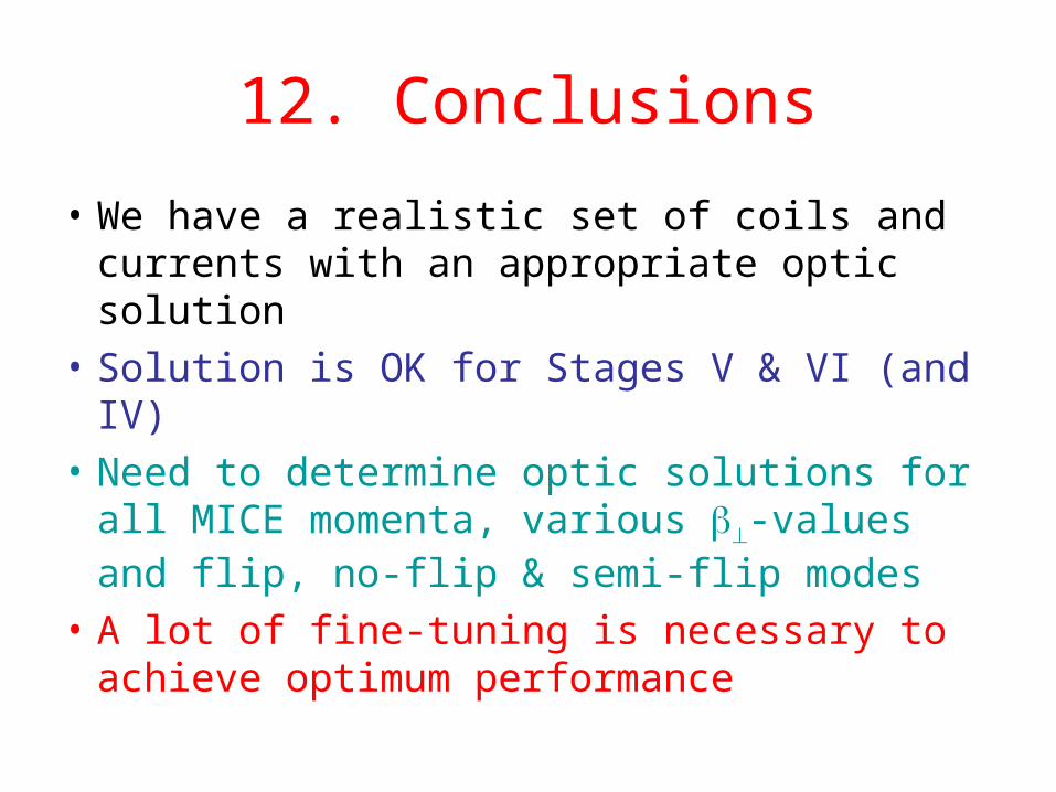
12. Conclusions
• We have a realistic set of coils and currents with an appropriate optic solution
• Solution is OK for Stages V & VI (and IV)
• Need to determine optic solutions for all MICE momenta, various -values and flip, no-flip & semi-flip modes
• A lot of fine-tuning is necessary to achieve optimum performance
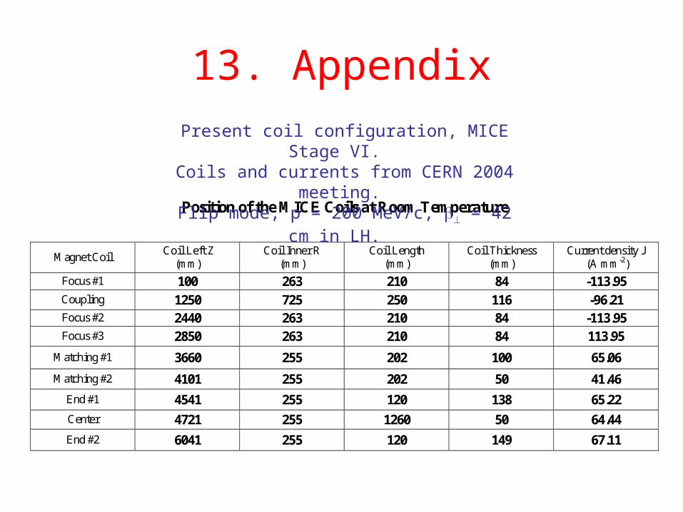
13. Appendix
Position of the MICE Coils at Room Temperature
Magnet Coil Coil Left Z
(mm) Coil Inner R
(mm) Coil Length
(mm) Coil Thickness
(mm) Current density J
(A mm-2)
Focus #1 100 263 210 84 -113.95 Coupling 1250 725 250 116 -96.21 Focus #2 2440 263 210 84 -113.95 Focus #3 2850 263 210 84 113.95
Matching #1 3660 255 202 100 65.06
Matching #2 4101 255 202 50 41.46
End #1 4541 255 120 138 65.22
Center 4721 255 1260 50 64.44
End #2 6041 255 120 149 67.11
Present coil configuration, MICE Stage VI. Coils and currents from CERN 2004 meeting. Flip mode, p = 200 MeV/c, = 42 cm in LH.
Top Related