


Languages
Pages
Legal


Carpentry and Joinery
Volume 3

This page intentionally left blank
Carpentry and Joinery
Volume 3Edition
Brian PorterLCG, FIOC, Cert Ed
Former Lecturer at Leeds College of Building
and
Christopher TookeLCG, FIOC, Cert Ed
Former Lecturer and Programme Manager at
Ealing, Hammersmith & West London College,
Chief Examiner for the Institute of Carpenters
AMSTERDAM BOSTON HEIDELBERG LONDON NEW YORK OXFORD
PARIS SAN DIEGO SAN FRANCISCO SINGAPORE SYDNEY TOKYO

Butterworth-Heinemann is an imprint of ElsevierLinacre House, Jordan Hill, Oxford, OX2 8DP30 Corporate Drive, Burlington, MA 01803
First published by Arnold 1986Second edition, 1991Reprinted 1999, 2001, 2003, 2004 (twice), 2005Third edition, 2007
Copyright © 1986, 1991, 2007, Brian Porter and Christopher Tooke. Published by Elsevier Ltd. All rights reserved
The right of Brian Porter and Christopher Tooke to be identified as the authors of this work has been asserted in accordance with the Copyright, Designs and Patents Act 1988
No part of this publication may be reproduced, stored in a retrieval system or transmitted in any form or by any means electronic, mechanical, photocopying, recording or otherwise without the prior written permission of the publisher
Permission may be sought directly from Elsevier’s Science & Technology Rights Department in Oxford, UK: phone (+44) (0) 1865 843830; fax (+44) (0) 1865 853333; email: [email protected]. Alternatively you can submit your request online by visiting the Elsevier web site at http://elsevier.com/locate/permissions, and selecting Obtaining permission to use Elsevier material
NoticeNo responsibility is assumed by the publisher for any injury and/or damage to persons or property as a matter of products liability, negligence or otherwise, or from any use or operation of any methods, products, instructions or ideas contained in the material herein. Because of rapid advances in the medical sciences, in particular, independent verification of diagnoses and drug dosages should be made
British Library Cataloguing in Publication DataA catalogue record for this book is available from the British Library
Library of Congress Cataloging-in-Publication DataA catalog record for this book is available from the Library of Congress
ISBN 13: 978-0-7506-6505-6ISBN 10: 0-7506-6505-X
Typeset by CharonTec Ltd (A Macmillan Company), Chennai, Indiawww.charontec.comPrinted and bound in Great Britain
07 08 09 10 11 10 9 8 7 6 5 4 3 2 1
For information on all Butterworth-Heinemann publications visit
our web site at http://books.elsevier.com

Contents
Foreword by David R Winson ix
Foreword by Christopher Addison x
Preface xi
Acknowledgements xiii
CHAPTER ONE PREFABRICATED BUILDINGS 1
1.1 Small demountable timber-framed structures 1
1.2 Timber-framed dwellings 6
1.3 Timber-framed curtain walls 19
1.4 Timber-framed infill panels 19
CHAPTER TWO EXTERNAL CLADDING 20
2.1 Cladding properties 20
2.2 Timber cladding 20
2.3 Detailing 27
2.4 Timber tiles 28
2.5 Plywood cladding 33
2.6 Surface finishes to timber cladding 35
2.7 Other claddings 36
CHAPTER THREE WINDOWS 39
3.1 Window profiles 39
3.2 Types of windows 42
3.3 Metal casement in wood surround 62
3.4 Glass louvred windows 64
3.5 PVCu (Polyvinyl chloride unplasticised) windows 66
3.6 Fixing window frames 68
3.7 Skylights (roof window) 73
3.8 Glass and glazing 79
3.9 Window boards 85
3.10 Sealants 87
3.11 Protection on site 87
3.12 Window hardware (ironmongery) 89
CHAPTER FOUR DOMESTIC DOORS, FRAMES AND LININGS 96
4.1 Classification (single-leaf door patterns) 96
4.2 Ledged-braced and battened door 99
4.3 Framed-ledged-braced and battened doors 105
4.4 Stable door 106
4.5 Panelled doors 107
4.6 Flush doors 113
4.7 Louvred doors 117
4.8 Double margin doors 120
4.9 Doors with curved top rail 124
4.10 Fire doors 125
4.11 Door frames 133
4.12 Door linings (often referred to as door ‘casings’) 137
4.13 Door schedule 140
4.14 Door hanging (door types) 141
4.15 Door sets 151
4.16 Domestic sliding interior doors 155
4.17 Storage and protection 156
4.18 Door hardware (ironmongery) 158
CHAPTER FIVE DOMESTIC GARAGE DOORS 180
5.1 Garage door types 180
5.2 Fitting and hanging hinged doors 181
5.3 Hardware 183
5.4 ‘Up-and-over’ single-door systems 186
5.5 Surface finish 189
CHAPTER SIX DOMESTIC GATES 191
6.1 Single personnel-access and garden gates 191
6.2 Domestic vehicle- and personnel-access gates 192
6.3 Gate hanging 194
6.4 Suitable material (for gate construction) 202
CHAPTER SEVEN STAIRS 203
7.1 Terminology 203
7.2 Design 206
7.3 Stair construction 213
7.4 Balustrades 232
7.5 Installation (site fixing) 233
7.6 Apron linings and bulkheads 236
7.7 Protection 237
7.8 Stair calculations 237
CHAPTER EIGHT WOOD WALL TRIMS AND FINISHES 249
8.1 Mouldings (shaped sections) 251
8.2 Architraves 259
vi Contents

8.3 Skirting boards 269
8.4 Rails around a room 276
8.5 Delft (plate) shelf 280
8.6 Cornice (drop or false cornice) 280
8.7 Infill panel frame 281
8.8 Raking moulds 282
8.9 Detection of services 284
CHAPTER NINE CASING-IN AND WALL PANELLING 286
9.1 Casings 286
9.2 Wall panelling 294
9.3 Fire performance (rate of flame spread) 303
9.4 Bath panelling 303
CHAPTER TEN JOINERY FITMENTS AND PURPOSE – MADE JOINERY 307
10.1 Shelving 308
10.2 Designing fitments 311
10.3 Wood drawers 319
10.4 Drawers made from plastics 325
10.5 Cupboard doors 327
10.6 Kitchen units 334
10.7 Finishes 339
CHAPTER ELEVEN SHORING BUILDINGS 341
11.1 Design 341
11.2 Types of shoring 342
11.3 Safety 350
CHAPTER TWELVE REPAIRS AND MAINTENANCE 351
12.1 General repairs survey 351
12.2 Customer relations 356
12.3 Hand/power tools and equipment 357
12.4 Remedial treatment 362
12.5 Door and window hardware 376
12.6 Making good repaired areas 376
12.7 Health and safety 376
Volumes and Chapters 381
Index 383
Contents vii

This page intentionally left blank

Forewordby David R Winson, Registrar of the Institute ofCarpenters
As with previous books in this series, anybody having an interest in car-
pentry and joinery, whether they are undertaking basic study, additional
study to prepare for an Institute of Carpenters advanced qualification, or
even purely as a reference work, will find this book an essential and
invaluable addition to their expanding toolkit.
This book, the last in a series of three, completes a superb set of refer-
ence works for carpenters and joiners. It provides the reader with step-
by-step practical advice and sufficient knowledge to reach competency
in a number of areas from prefabricated buildings, through stair con-
struction and on to repairs and maintenance of existing buildings. Its
text is concisely and factually written, the accompanying illustrations
are clearly defined, and where calculations are necessary they are
explained in an easy to understand manner, helping the reader to
quickly come to terms with the subject matter.
Throughout its pages the book gives unequivocal guidance, particularly
in regard to the Building Regulations, Health and Safety and other
equally important regulations, enabling the reader to carry out a wide
range of different work competently but above all else, safely.
It has again been a privilege to be able to review this revised and
updated edition of a much renowned textbook used extensively by those
engaged in teaching the craft of carpentry and joinery. This book, along
with the other two books of the series, has been included in the Institute
of Carpenters’ recommended reading list for nearly two decades and
will continue to be so.
It has been particularly so in the knowledge that the authors, both of
whom I have the privilege of working with, are members of the Institute
with a great many years’ experience, and membership, to call upon.
I wish all readers every success in their chosen careers and I am con-
fident that this book will, like the others in the series, assist greatly in
that success.

Forewordby Chris Addison, Technical Officer of the BritishWoodworking Federation
It is a pleasure, on behalf of the British Woodworking Federation, to
welcome a new edition of an established textbook on Carpentry and
Joinery. Since the original publication twenty years ago, this series
has become a classic companion for both the student and the work-
ing carpenter and joiner.
Acknowledged experts Brian Porter and Christopher Tooke have
completely revised this volume, adding new material and bringing it
fully up to date for the twenty-first century. We particularly welcome
the extended coverage on the use of fire doors and frames, as part of
passive fire protection.
It is always a challenge to keep up to date with Building Regulations
and the industry standards whether British, European or interna-
tional, and the useful end-of-chapter references direct the reader to
the relevant information.
From the standpoint of the timber and woodworking industry, the
BWF wishes this valuable publication every success.

Preface
The Building Industry is constantly changing with the introduction
of new ideas and innovations. Since the last edition of Book 3 we
have witnessed numerous changes to the Building Regulations and a
movement to bring British Standards in line with Europe. Further
pieces of legislation have also had a marked effect on our trade and
how we operate – particularly in regard to Health and Safety.
Changes in the type, and sourcing of our main raw material ‘wood’
in whatever form it takes – be it timber or manufactured boards, is an
issue we cannot ignore. Many tropical hardwoods that were once
freely available are now more difficult to obtain.
Hardwood and Softwood now come from sustainable sources that
use proper forest management. Before wood in its many forms is
exported to the UK, it is certificated by one of the following organi-
zations and marked accordingly. This mark identifies that the wood
has been cut from trees within a sustainable forest. For example:
• FSC (Forest Stewardship Council)
• CSA (Canadian Standards Association)
• PEFC (Programme for the Endorsement of Forest Certification)
• MTCC (Malaysian Timber Certification Council)
Training needs for students have also seen major changes, with a much
greater emphasis towards work based on the job training – qualifications
now available to the Carpenter & Joiner now include:
Qualification Level Available Awarding Body
NVQ (National Wood Occupations:Vocational Levels 1, 2, & 3Qualification)
SVQ (Scottish Wood Occupations:Vocational Levels 1, 2, & 3Qualification)
Construction Wood Occupations:Award ● Foundation
● Intermediate● Advanced
(Continued)
� CITB (ConstructionIndustry TrainingBoard) and C&G(City & Guilds)

With this revised new edition, we have taken into account all the
changes we thought necessary to furnish the reader with current updated
information. Together with Volumes 1 & 2 this should meet the require-
ments necessary for their endeavour to gain enough knowledge within
their chosen Wood Occupation (Carpentry and Joinery) to be successful
in their examinations and chosen career.
Because of the extensive cross-reference index in the book you should
find navigating through it and across the series quite a simple task.
Furthermore, references to Building Regulations, British Standards
etc., are included at the end of each section.
This book has been revised to compliment new editions of Carpentry &
Joinery 1 and Carpentry & Joinery 2. As with all the books in the series,
you will find that due to its highly illustrative content, it is very easy to
follow. We believe that a textbook of this nature, deserves well-detailed
pictures and annotated diagrams which speak louder than words.
The first edition of this book came into print over 20 years ago and
has proved itself time and time again as a valuable source of refer-
ence to students of all the wood trades across the world.
Finally, we both feel and ardently believe that Brian’s final sentence
of the Preface in his first edition to Volume 2, is as important as
ever – if not more so now . . . “Perhaps it could be said that the good
craft worker is one who signs his or her work with pride.”
Brian Porter & Christopher Tooke
xii Preface
Qualification Level Available Awarding Body
IOC Carpentry Carpentry & Joinery:and Joinery ● Foundation
● Intermediate Institute of Carpenters● Advanced Craft
(MIOC)● Fellow (FIOC)
Master ● Carpentry Institute of CarpentersCertificate ● Joinery The Worshipful CompanyScheme ● Shopfitting of Carpenters
City and GuildsThe Worshipful Companyof Joiners and Ceilers
�

Acknowledgements
This new Third Edition of Carpentry and Joinery would not have
been possible without the kind help and assistance of the following
companies and organisations who supplied us with technical infor-
mation and permission to reproduce their artwork and photographs.
For this we are both very grateful.
Celuform Ltd, Glass and Glazing Federation, Pilkington (UK) Ltd,
Royde and Tucker (Architectural Ironmongery) Ltd, Scandia-Hus
Ltd, and Timber Research and Development Association (TRADA).
Company Figure Number(s)
“balanceuk” Ltd 3.24
Building Research Establishment (BRE) 1.8(a), 1.8(b), 1.8(d),
1.8(e)
Bosch UK Ltd 8.43
Chasmood Ltd 4.89, 4.90
Christopher Addison-British 4.37, 4.38
Woodworking Federation (BWF)
Chubb Ltd 4.76(b), 4.96
Clico (Sheffield) Tooling Ltd 8.8
Fisher Fixing Systems Ltd 3.34
Freidland Ltd (Bell push) 4.97
Henderson Garage Doors Ltd 5.13
Ingersoll-Rand Business Ltd (Briton 4.87
Door Closers)
Jeld-Wen UK Ltd 3.30, 3.31
Josiah Parks (Union) 4.91, 4.95, 4.96, 4.97
Makintosh and Partners Group Ltd 8.5
National House Building Council 3.43, 3.44
(NHBC)
Naco Windows (Ruskin Air 3.27, 3.28
Management) Ltd
Reynolds (UK) Ltd (Crompton 3.65, 4.71, 4.72, 4.79,
Hardware, ERA and Yale) 4.80, 4.81, 83(b), 4.85,
4.96, 4.97, 5.3 to 5.11,
6.9 to 6.13
Selectaglaze Ltd 3.52
Slik Sliding Door Gear Ltd 10.27, 10.28
Solatone (Door bell) 4.97
Stewart Milne Timber Systems Ltd 1.8(f)

xiv Acknowledgements
The Bath Knob Shop (tBKS) 3.61, 3.62, 3.66, 3.67,
Architectural Ironmongery 4.69, 4.78, 4.88, 4.93
Titon Ltd 3.60, 3.63, 3.64
Trend Machinery & Cutting Tools Ltd 4.62, 7.15, 10.32, 10.33,
10.34, 10.35
Velux Company Ltd 3.36, 3.39, 3.40
Finally, we would both like to thank Hilary Yvonne Porter once again
for her continual help, patience and support during the writing of this
new third edition.

In many situations, prefabricated timber buildings provide an alter-
native to traditional (masonry) on-site building.
The components which go towards constructing load-bearing walls,
and in some cases the floors and roof, are either fully or partially pre-
fabricated. This process can be carried out on site, but in the UK it will
almost certainly be done within a factory, where conditions can be con-
trolled and operatives are not hindered by unreliable weather.
Once the on-site foundations have been constructed, the pre-made units
or components can be delivered and erected as and when required.
The main advantage of prefabrication compared with fabrication on
site is that the superstructure can be erected very quickly to form a
weather-resistant envelope, thereby providing a sheltered environment
for greater work continuity across the building trades.
Whether the building is to be demountable (capable of being disman-
tled and reassembled elsewhere) or a permanent fixture will mainly
depend on its use and size.
Structures of this type may be used as site huts for temporary accom-
modation. Although more commonly used these days, prefabricated,
proprietary modular units are generally employed. These not only pro-
vide temporary accommodation for site personnel and their equipment,
but also offer storage space for perishable and/or valuable building
materials.
However, garden sheds and summer-houses are usually constructed as
timber-frame structures.
Prefabricatedbuildings
1
1.1 Smalldemountabletimber-framedstructures

The floor, sides, and roof may consist of one or more panels. These
panels are joined together at their corners and along their length with
coach bolts or similar devices capable of cramping and holding the
joint temporarily or permanently secure.
2 Prefabricated buildings
A1 B1 B2
C1 D1 D2
C1 C1A1
A1
B1
A1
A1
B1 � Right side openingB2 � Left side opening
A1
A1D2D1
(b)
A1
(a)
Interchangeable module system,e.g. 1.2 m, 2.4 m or 1.5 m, 3.0 m, etc.
Coats,boots Partition
Hatch Drawings chest
Worktop – drawings under
Diagonal brace – solidtimber noggings or
galvanized-steel bracenotched into studding Door
Fillet
(c)
Stable
Stable
Unstable(Weatherboard clad)
(Plywood clad)
Coach bolt
Coverlaths (d)
(e)
Rubber gasket(draught- andweather-seal)
Bolt check Exterior cladding
Pocket cut in inner lining –spanner access
Note: Shutters over windows optional
Fig. 1.1 Timber-framed wall panels.

Small demountable timber-framed structures 3
1.1.1 Construction and erection
It is common practice to make panels to a modular size (say multiples
of 500 mm or 600 mm) to suit board or timber lengths – panels can
then be interchangeable as shown in Fig. 1.1a. In this way (provided
that structural stability is not affected), a door or window can be sited
to suit almost any situation.
Figure 1.1b shows a possible floor layout of a site hut using six panel
variations. Except for the partition, the order for the wall panels might
read as follows in Table 1.1.
1.1.1.1 Walls
Wall panel sizes vary, being often influenced by:
(a) the type of building;
(b) the size and type of cladding;
(c) transportation;
(d) handling techniques, for example, by hand or machine.
The structural strength of a panel is derived from the row of vertical
members called ‘studs’. Studding is trimmed at the top by a head-
piece, and at the bottom with a sole-piece of the same sectional size.
All the joints are nailed.
If panels are to be externally clad with a strip material, e.g. weather-
board, etc. (see Chapter 2), the framework should be diagonally cross-
braced to prevent ‘racking’ (lateral movement) as shown in Fig. 1.1c.
Diagonal noggings of solid timber or perforated galvanized-steel
strapping, let into and nailed on to studding under the cladding, can be
used as bracing as shown in Fig. 1.1c. Diagonal cross-bracing is not
always necessary when the frames are clad with a sheet material – an
exterior cladding of exterior-grade plywood can provide very good
resistance to racking.
Figure 1.1d shows how panels can be joined together. If the panels are
lined on the inside – possibly to house some form of insulation material
between the studding – pockets should be left to allow access to coach
bolts, etc. A more effective joint can be made by introducing a rubber-
type gasket between the edges of the panels as shown in Fig. 1.1e – as
the bolts are tightened, an airtight and watertight seal is formed.
1.1.1.2 Floors
Floor panels should be as large as practicable and decked with
tongued-and-grooved boards or exterior-grade plywood. Panel sizes

must be adaptable to wall modules, and provision must be made for
bolting panels together and for anchoring the walls to them, as well
as for fastening down to ground sleepers, as shown in Fig. 1.2. Floor
panels may also incorporate thermal insulation (see also Volume 2,
section 5.3 Thermal insulation).
1.1.1.3 Roofs
Whole roof sections can be prefabricated as shown in Fig. 1.3a to drop
on to and be anchored to wall sections via bolt-on angle plates or steel
straps. Joists may be cut from the solid, laminated or, for lightness,
fabricated using the box–beam method (a solid timber framework
clad both sides with an exterior-grade plywood). Thermal insulation
may be incorporated within roof sections (but see Volume 2,
4 Prefabricated buildings
Table 1.1 Order of wall panels Site hut (see Fig. 1.1) – wall panels 1.2 m (type 600 module)
Panel code Number
A1 7B1 1B2 0C1 2D1 1D1 1
Total number of panels 12
Floor panel
End-grainexposure
reduced byusing header
Wall panel
Cladding
Joist/header
Anchor strap
Double-headed(duplex) nails
Sleeper (preservative-treated)
Inner lining (optional)
Angle plate/gutter bolt (optional)Decking (plywood) Floor panels
(joint bolted)
Insulation (optional)
Extended toform drip
Fig. 1.2 Floor panels and wall-
to-floor details
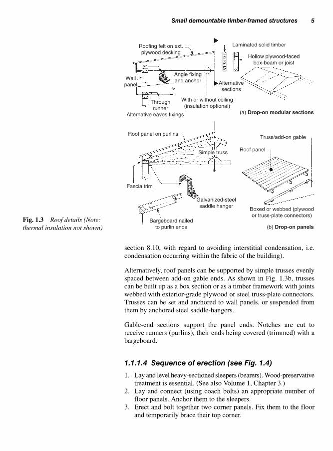
section 8.10, with regard to avoiding interstitial condensation, i.e.
condensation occurring within the fabric of the building).
Alternatively, roof panels can be supported by simple trusses evenly
spaced between add-on gable ends. As shown in Fig. 1.3b, trusses
can be built up as a box section or as a timber framework with joints
webbed with exterior-grade plywood or steel truss-plate connectors.
Trusses can be set and anchored to wall panels, or suspended from
them by anchored steel saddle-hangers.
Gable-end sections support the panel ends. Notches are cut to
receive runners (purlins), their ends being covered (trimmed) with a
bargeboard.
1.1.1.4 Sequence of erection (see Fig. 1.4)
1. Lay and level heavy-sectioned sleepers (bearers). Wood-preservative
treatment is essential. (See also Volume 1, Chapter 3.)
2. Lay and connect (using coach bolts) an appropriate number of
floor panels. Anchor them to the sleepers.
3. Erect and bolt together two corner panels. Fix them to the floor
and temporarily brace their top corner.
Small demountable timber-framed structures 5
Roofing felt on ext.plywood decking
Wallpanel
Angle fixingand anchor
Laminated solid timber
Hollow plywood-facedbox-beam or joist
Alternativesections
Throughrunner
With or without ceiling(insulation optional)
Alternative eaves fixings (a) Drop-on modular sections
(b) Drop-on panels
Roof panel on purlins
Fascia trim
Simple truss
Bargeboard nailedto purlin ends
Galvanized-steelsaddle hanger
Boxed or webbed (plywoodor truss-plate connectors)
Roof panel
Truss/add-on gable
Fig. 1.3 Roof details (Note:
thermal insulation not shown)

4. (a) Form the adjacent end corner;
(b) Add the internal partitions (if any);
(c) Loosely bolt on the remaining panels;
(d) Check for alignment and squareness – add temporary corner
braces;
(e) Tighten all nuts. Fix to the floor.
5. (a) Bolt on gable sections and fix intermediate trusses; or
(b) Drops on and bolt together whole roof sections.
6. (a) Lay and fix roof panels;
(b) Tape over the panel and ridge joints with waterproof self-
adhesive tape;
(c) Fix trim – the eaves and barge-board.
These are permanent buildings consisting of an outer timber frame-
work structurally designed to support an upper floor and/or a roof
structure. All loads are transmitted to the foundations via the timber-
studded framework. This studded wall framework can be built up by
one of two methods:
(i) balloon-frame construction, or
(ii) platform-frame construction.
In balloon-frame construction (Fig. 1.5), which is generally not used
much in the UK, the wall panels extend in height from the ground floor
to the eaves. The upper floor is suspended from within the full-height
studded wall structure. Load-bearing partitions can offer mid-support.
In platform-frame construction (Figs 1.6 and 1.7) storey-height wall
panels are erected off the ground-floor platform. These load-bearing
panels provide support for the upper-floor platform, off which the
upper wall panels are erected.
6 Prefabricated buildings
Lay and level sleepers Lay floor panels Erect corner panels
Add partition and
remaining wall panels
Fix gable ends and
intermediate trusses or
modular roof sections
Lay/fix (anchor) roof
sections/panels, tape
(waterproof tape) panel
and ridge joints, fix
bargeboard and trim
1 2 3
4 5 6
Fig. 1.4 Site hut assembly
details
1.2 Timber-framed dwellings

Stu
d h
eig
ht
Corner brace(temporary)
Single panel
Temporarystays (props)
Corner/side-wall panelsBase/foundation(ground floor)
1 2
Roof carcaseStructural shellframework
3 4
Fig. 1.5 Balloon-frame con-
struction and stages of erection
Stu
d h
eig
ht
Stu
d h
eig
ht
Single panel
See Fig. 1.7 (‘A’, ‘B’, ‘C’)
Temporary stays(props)
Ground-floor platform1 Ground-floor wall panels2
Upper-floor platform3 Upper-floor wall panels4
Roof carcase5 Walls clad – roof covered6
A
B
C
Fig. 1.6 Platform-frame con-
struction and stages of erection

8 Prefabricated buildings
Isometric detailat ‘B’ (Fig. 1.6)
Insulation boardTruss-plate connector
Truss clip
Tilt fillet
Fascia Vent
Soffit board
Brick cladding
Sheathing
Packing
Breather membraneHeader, 50 × 195
Head-binder, 97 × 44
Head-binder, 97 × 44
Blocking, 50 × 195
Joist, 50 × 195
Cavity barrier
Top rail of wallframe, 97 × 44
Top rail of wall frame
Bottom rail of wall frame, 97 × 44
Inner lining
Vapour control layerCavity barrier
Thermal insulation
Wall tie
Bottom rail of wallframe, 97 × 44
Sole-plate, 100 × 60,nail-fixed via cartridge-
fixing tool or strap anchoror anchor bolt
Concrete floor slab
Insulated screed DPM
Panel 2365
Ventilation
Thermal insulation
Ceiling
Studding at 600 centres
Decking
Header
Possible details about ‘C’ (Fig. 1.6)
Possible details about ‘B’ (Fig. 1.6)
Possible details about ‘A’ (Fig. 1.6)Cover lath
15 mm gap forthermal movement
Sheathing Stud
Joists
Fig. 1.7 Vertical section through platform-framed construction – see Fig. 1.6
Figure 1.8a–f illustrates the main stages in the erection of a partially
off-site prefabricated timber-frame house. (Not all the photographs
are of the same house.) It should be noted that in these cases the
breather membrane (as shown in Fig. 1.8(f)) is fixed over the face of the
panels in-situ; in this way the probability of a pre-covered panel
becoming damaged while in transit or stored on site is avoided.
However, many manufacturers prefer to pre-cover their panels, to
ensure early weather protection to the building as a whole.
With both methods, the roof structure bears upon load-bearing wall
panels.
Nearly all timber-framed houses in the UK are built using the platform-
frame construction method; therefore the text that follows refers to
this method.

Panels may be constructed by one of three methods:
(i) Stick built: this is the least popular method, which involves fab-
ricating all the panels on site.
Timber-framed dwellings 9
1.2.1 Wall construction
(a) Soleplate in place, used to provide a floor screed. Notice the provision for service pipes
(b) Exterior corner panels being erected
(c) Interior studwork showing temporary bracing for stability
(d) Roof trusses pre-assembled over ground floor slab – prior to being lifted up in place
(e) Part of pre-assembled roof being lifted and lowered into position
(f) Exterior cladding in progress on left hand construction
Fig. 1.8 Erection of a timber-framed house

(ii) Partial off-site prefabrication (Fig. 1.9a): a jig-built studded
framework is clad with a sheathing (sheet material – usually
exterior-grade plywood see Volume 1, section 4.1.2) to prevent
racking and is then often covered with a breather membrane
(see Figs 1.10 and 1.11). Insulation, a vapour control layer, and
10 Prefabricated buildings
Off-site partprefabricated
Off-site fullyprefabricated
Add-on brickcladding
Moisture barrier
Top rail
Sheathing
Stud
Breathermembrane
(moisture barrier)
Bottom railFlexiblewall tie Vapour
controllayer
Vapourcontrollayer
Timbergrounds
Innerlining
(a) Panel (b) Brick cladding (c) Timber claddingFig. 1.9 Wall panel types
(e) Insulation (e.g. rock or glass mineral wool)
(b) Sheathing (WBP Ply, OSB, etc.)
Outside dwelling(exterior)
Inside dwelling(interior)
Vertical section
Horizontal section
(d) Breather membrane (also acts as a temporary weather shield)
(a) Timber stud
(c) Vapour control layer
(f) Lining (e.g. plasterboard/ fibreboard)
Fig. 1.10 Part vertical and
horizontal sections through a
wall panel

Timber-framed dwellings 11
an inner lining are fixed on site after the house has been made
watertight. The panel size will depend on the means of transport
and the site-hoisting facilities available.
(iii) Fully off-site prefabricated panels: if the building is to be clad
with masonry (i.e. brickwork), then the panels will include wall
ties prefixed to the studs via breather-membrane-covered sheath-
ing, bitumen-impregnated fibreboard, or OSBs (orientated strand
board) (see Volume 1, Table 4.10), as well as insulation, a vapour
control layer, and the inner lining, as shown in Fig. 1.9b.
Timber-clad panels (Fig. 1.9c) could include pre-fixed windows.
Figure 1.10 shows part vertical and horizontal sections through a
completed panel. Components include:
(a) Structural timber studs: these are usually ‘structural’-graded soft-
wood, sawn or (more likely) planed finish. Preservative treatment
will be required in most cases. Hardwoods may also be used.
The stud sections are 38 mm minimum finished thickness (usu-
ally 45 mm), with a width of 95 mm finish (or wider, to accommo-
date the necessary thickness of thermal insulation material).
(b) Sheathing: the most common sheet materials are:
(i) Plywood – structural sheathing quality, bonded to WBP stand-
ard (see Volume 1, section 4.1.2).
(ii) OSB (orientated strand board) – multi-layer board, cross-
banded in a similar fashion to 3-ply-veneer plywood (see
Volume 1, section 4.5).
(iii) Medium board – should be stiff enough to provide racking
resistance (see Volume 1, section 4.6.3).
(iv) Bitumen-impregnated fibreboard – racking resistance of the
panel must be provided by other means (see Volume 1, Table
4.10). Provided that the panel joints are sealed, breather mem-
brane may be omitted.
Exterior Interior
Watervapour
Cla
ddin
g
Ventilated cavity
Breather membrane
WBP Ply or OSB as sheathing
Vapour control layerwell lapped at all times
Fig. 1.11 Providing a vapour
check

(c) Vapour control layer: this is usually a 250 or 500 gauge polythene
membrane fixed to the warm side of the insulation (see also
Volume 2, Fig. 5.8). All joints should meet on studs or noggings
and should overlap by at least 100 mm. Stainless steel staples
should be used.
(d) ‘Breather’ membrane: this is a waterproof membrane which helps
keep the timber-framed shell weathertight but, because of its per-
meable nature, allows water vapour to escape from inside the
dwelling as and when required to do so.
(e) Insulation material: this must be a permeable type of either rock
wool or glass mineral wool. A thickness of 90 mm would give a
U-value (see below) of about 0.32 W/(m2°K) through the whole
wall structure (including cladding), which is nearly double the
statutory requirement to satisfy the Building Regulations Approved
Document L1, 2002.
(f) Lining: suitable lining materials and the requirements regarding
surface spread of flame are the same as those for partitions, as
discussed in Volume 2, section 9.4.2.
Figure 1.11 shows how the vapour check is made – its presence should
prevent moisture in the warm air entering the insulation-filled (or
partly filled) cavity and condensing out as it reaches the dew point (the
temperature at which dew begins to form) at or near the cold outer sur-
face. An inadequate vapour control layer could result in the insulation
becoming wet and ineffective and increase the moisture content of the
timber framework. However, because it is almost impossible to achieve
a 100% vapour check, those small amounts of vapour which do pass
through should be allowed to continue unhindered via the permeable
breather membrane into a ventilated cavity (all forms of cladding
should be vented behind) where they can disperse freely.
Figure 1.12a shows a skeleton view of a panel, with a lintel over a win-
dow opening, being connected to a similar panel at a corner. All panel
joints are butted together – the method of securing the joints will depend
on the panel type and corner details, etc. (Figs 1.12b and c). Further to
nailing and using metal corner straps, the timber head-binders should
lap all the panel joints, both at corners and on the straight.
In Fig. 1.12c it can be seen how provision has been made for services
(electric and telephone cables, etc. in suitable trunking) by rebating
the edges of each panel. A plough groove houses a loose tongue which
serves as a location aid, panel stiffener, and draught-seal. Rubber
draught-seals can be provided at corners and floor levels.
Panels can be secured at ground-floor level via a timber sole-plate pre-
viously fixed to the concrete floor slab (see Fig. 1.7). (Fixing to a tim-
ber-suspended ground floor is shown in Volume 2, Fig. 5.8.) Upper
floor and roof connection details are also shown in Fig. 1.7. (See also
Volume 2, Fig. 7.6, for arrangements with a flat roof.)
12 Prefabricated buildings
Note: Temperature difference mayalso be expressed in celsius (C). As a temperature difference of 1 C � 1 °K, a U-value is the samewhether expressed in W/(m2 °C) orW/(m2 K).

U-value, or ‘thermal transmittance’, provides a measure of the rate at
which heat will flow through a building structure between two envir-
onments at different temperatures. It is the rate of heat flow (in watts)
through one square metre of the structure when the environmental
temperatures on each side differ by 1°K, and it therefore has the units
watts per metre squared per °C or W/(m2°K).
Timber-framed dwellings 13
Head-binder
Joist 450–600 centres
in line with studs
Top rail of wall frame
Internal lining
Vapour control layer
Thermal insulation
Sheathing
Vapour control layer
Lintel
Sill
Cripple stud supporting lintel
Stud
Bottom rail of wall frame
Sole-plate over DPC
(a)
Butt joint
Plywood
sheathing
Corner
add-on
Ext. corner
Inner lining –
e.g. medium board
(fire-retarding grade)Rubber
draught-seal
Galvanized-steel
fixing plate
Loose tongue Sheathing
Sheathing-clad skeletonpanel modules
Fillet Channel for services
(c)
(b)
Example of joining fully prefabricated panels (single-storey buildings)
75 mm nails,
min. 6 at min. 400 centres
vertically staggered
Note: Insulation not shown
Fig. 1.12 Timber-framed wall connection details
1.2.2 U-value

Each component in the structure, and the air layer on each side of the
structure, has its own thermal resistance to heat flow (see below), and
the U-value of the assembled structure is calculated from
where Rtotal is the sum of all the thermal resistances offered by the com-
ponents of the structure, and the air which surrounds them, at any given
point in the structure. To find the thermal resistance of a material, we
must know its thermal conductivity and hence its thermal resistivity.
This gives an indication of an individual material’s ability to conduct
heat. It is the rate of heat flow (in watts) through one square metre of
a sample of material one metre thick when there is a temperature dif-
ference of 1°K between the surfaces of the material; it therefore has
U-value1
total
�R
14 Prefabricated buildings
Table 1.2 Typical values of thermal conductivity and thermal resistiv-ity for various materials and products
Thermal Thermalconductivity (k) resistivity (1/k)
Material (W/(m °K)) (m °K/W)
Air 0.026 38.46Expanded polystyrene 0.034 29.41Balsa wood 0.040 25.00Fibreglass (glass-wool fibre) 0.040 25.00Fibreboard – insulation and 0.053–0.065 15.38–18.87
medium board (varies with density and m.c.)
Bitumen-impregnated fibreboard 0.070 14.29Hardboard (fibreboard) 0.080 12.50Aerated-concrete building 0.110–0.196 5.10–9.09
blocks (varies with density)Softwood 0.130 7.69Hardwood 0.150 6.67Chipboard 0.150 6.67Plasterboard 0.160 6.25Plastering 0.380 2.63Glass 1.050 0.95Brick work – commons (varies 1.250 0.80
with density)Concrete (dense) 1.430 0.70Steel 50.00 0.02Aluminium alloy 160.00 0.006
1.2.3 Thermalconductivity (k)

the units (W/m2)/(m °K) or W/(m °K), i.e. watts per metre per °K (or
W/(m C) if temperature differences are quoted as celsius).
Manufacturers of building materials quote the thermal conductivity
as an indication of a material’s thermal performance – the lower the
thermal conductivity, the greater the material’s resistance to heat flow
through it. For example, typical thermal conductivities might be:
for brickwork 1.25 W/(m °K)
for woodwork (solid) 0.13 W/(m °K)
Therefore wood has a much greater resistance to heat transfer, i.e. it
is a better insulator, than brickwork. Table 1.2 gives other typical
values of thermal conductivity.
This gives an indication of a material’s ability to resist the flow of
heat and is defined as the reciprocal of thermal conductivity, i.e. 1/k.
Its units are therefore m °K/W (or m C/W).
For a particular thickness of material, this gives the resistance to heat
flow through one square metre of the material when there is a tem-
perature difference of 1 °K between the surfaces of the material. It
has the units m2°K/W (or m � C/W) and is calculated by multiplying
the thermal resistivity by the thickness of the material. For example,
for glass fibre with a thermal conductivity (k) of 0.04 W/(m °K),
For a thickness of 90 mm (0.09 m) of this glass fibre,
thermal resistance � thermal resistivity � thickness
� 25 m °K/W � 0.09 m � 2.25 m2°K/W
Values of thermal resistance can be used to calculate the U-value of
a structure. It is usual to take arbitrary figures for the thermal resist-
ances of the air layers on each side of the structure (remember that
U-values relate to differences between environmental temperatures,
not surface temperatures) and for any air gaps within the structure,
as shown in the example below.
thermal resistivity1
1
0.04 W/(m K)25 m K/W
�
� �
k
��
Timber-framed dwellings 15
1.2.4 Thermalresistivity (r)
1.2.5 Thermalresistance (R)

16 Prefabricated buildings
Assuming that the section through the wall panel shown in Fig. 1.10
consists of the following (disregarding the vapour control layer and
the breather membrane):
Material Thickness
Plasterboard 12.5 mm
Glass-fibre insulation (mineral wool) 90 mm
Plywood sheathing 9.5 mm
then the U-value of the panel can be determined by first calculating
the thermal resistance of each element in the structure, using the val-
ues for k given in Table 1.2.
For example, for the plasterboard
The following table can be drawn up:
k
k
�
�
0.16 W/(m K) from Table 1.1
1 1
0.16 W/(m K
�
�∴
))6.25 m K/W
thickness 1.27 mm 0.0127 m
1
�
� �
� �
�
∴ Rk
tthickness
6.25 m K/W 0.0127 m
0.08 m K/W2
� �
�
�
�
Thermal Thermal ThermalThick- conduc- resis- resistance,ness, T tivity, k tivity, 1/k R � T � 1/k
Material (m) (W/(m °K)) (m °K/W) (m2°K/W)
Plasterboard 0.0127 0.16 6.25 0.08
Glass-fibre 0.09 0.04 25 2.25insulation
Air space 0.18within cavity (arbitrary value)
Plywood 0.0095 0.14 7.14 0.07sheathing
Inner and 0.18outer surface air layers (arbitrary value)
Total thermal resistance 2.76

For the panel section, therefore
These provide a means of closing the cavity and limiting the volume
of the cavity between the timber framework and any external
cladding (brickwork, etc.) or connecting elements – in the event of a
fire, the cavity could otherwise allow smoke and flame to spread
through or around the structure. Location and distribution of cavity
barriers must satisfy the requirements of the Building Regulations
Approved Document B, Fire Safety: 2000.
A cavity barrier may, for example, be constructed of:
(a) timber not less than 38 mm thick;
(b) steel not less than 5 mm thick;
(c) calcium silicate, cement-based or gypsum-based plasterboard
not less than 12.0 mm thick;
(d) wire-reinforced mineral wool blanket not less than 50 mm thick.
These are seals of non-combustible material used to close an imperfec-
tion of fit between building elements and components, for example,
where smoke and flame could otherwise pass. For specific locations, see
the Building Regulations Approved Document B, Fire Safety: 2000.
In the event of a possible fire, timber used as an external cladding may
increase the likelihood of the fire spreading to other buildings. Generally,
domestic buildings must be separated by a space of at least 1 m and
restricted to wall areas of 3 storeys in height and 24 m in length. See the
Building Regulations Approved Document B, Fire Safety: 2000.
Over the past few years there has been a slight increase in this form
of building construction, where the units are made under factory con-
ditions, in a dry environment and quality controlled. This reduces the
risk of on-site defects associated with traditional forms of construction.
Once prefabricated in the factory, these large pre-finished sectional
units are then connected together on site to form a whole house – a
highly specialized operation requiring special production techniques,
transportation, and lifting facilities.
U-value1
1
2.76 m K/W
0.36 W/(m K)
total
2
2
�
�
R
�
�≈
Timber-framed dwellings 17
1.2.6 Cavity barriers(see Fig. 1.7)
1.2.7 Fire stops
1.2.8 Fire spread
1.2.9 Volumetric houseunits (whole or part off-site houseprefabrication)
Note: In the above calculation, noallowance has been made for sec-tions including a stud. If externalcladding had also been included,the overall U-value would havebeen in the region quoted earlier(0.32 W/(m2 °K)).

18 Prefabricated buildings
Note: With this method of building, the main load-bearing structure must beprovided with lateral support and resistance to racking.
Roof
Front elevation (façade)
Columns of structural framework
Joint Joint Joint
Non-load-bearing panels (curtain wall) covering structural framework
Horizontal section A-A
A A
Fig. 1.13 Timber-framed panels
forming a curtain wall
Roof
Front elevation (façade)
Masonry cross-wall
Timber-framed infill panel
Horizontal section A-A
A A
Fig. 1.14 Timber-framed infill
panels

Timber-framed infill panels 19
Originally introduced in 2001 (as part of Approved Document L1:
Conservation of Fuel and Power) with the latest revision in 2006, its
purpose is to determine the energy efficiency on all new construction
in relation to insulation, heating, lighting, etc.
A SAP rating may vary between 1 and 100, indicating the higher the
range the more energy efficient the property.
Furthermore, it will give the prospective home owner an idea of
the probable running cost of the property and its effects on the
environment.
These form a non-structural façade to cover a framed load-bearing
structure. An example of how light timber-framed panels can be used
for this purpose is shown in Fig. 1.13. Although the panels are lighter,
their construction and insulation techniques are similar to those already
mentioned. The panels will rely on the main substructure for their
fixing and support.
By using masonry cross-walls (either end or party walls) to support
all the main load-bearing parts of a building, for example the floors
and the roof, the front and back walls can, in some situations, be made
as an infill panel (or panels) as shown in Fig. 1.14.
1.3 Timber-framed curtainwalls
1.4 Timber-framed infillpanels
References
Building Regulations Approved Document L1, Conservation of Fuel
and Power in Dwellings, 2002 (SAPs).
Building Regulations Approved Document B, Fire safety: 2000.
BS 5268–6.1:1996, Structural use of timber. Code of practice for
timber walls. Dwellings not exceeding four storeys.
BS 1282: 1999, Wood Preservative. Guidance on choice use and
application.
BS 4072: 1999, Preparations for wood preservatives.
BS 4261: 1999, Wood Preservation. Vocabulary.
BS 5589: 1989, Code of practice for wood preservation.
BS 5268–5: 1989, Structural use of timber, code of practice for the
preservative treatment of structural timber.
BS 5707: 1997, Specification for preparations of wood preservatives
in organic solvents.
TRADA Timber-framed construction.
BRE Timber-framed construction information sheet.
NORDIC Timber construction buildings.
BBA (British Board of Agreement).
1.2.10 StandardAssessmentProcedures (SAPs)

No matter what form it takes, cladding provides a non-load-bearing
weather protection and in most cases a decorative finish to whatever
structure it is required to cover.
Any material may be used as a cladding provided that it is available
in an acceptable form, and that it possesses the necessary properties,
for example:
(a) weather resistance;
(b) durability;
(c) strength to resist impact;
(d) resilience to abrasion;
(e) fire performance;
(f) thermal insulation;
(g) minimal maintenance
and that it complies with current regulations (Approved Document
B4 2000, Fire spread).
The relationship between the material, its form and type, is shown in
Table 2.1 with reference to Fig. 2.1.
In the UK, brickwork is more often than not the main external cladding
used with timber-framed houses. However, if other cladding mater-
ials are not used all over, they are often included in the design and used
alongside brickwork or stonework as a form of visual relief. Examples
of how this could be achieved are shown in Fig. 2.2.
Timber used as a cladding material has been common practice since
the early days of house building as a protection against the elements.
Depending on the timber species, the climatic conditions, and any pre-
servative treatment, its life span can exceed 50 years – any boards that
do show signs of decay or defect at a later date can easily be replaced.
External cladding2
2.1 Claddingproperties
2.2 Timbercladding

Timber cladding 21
Table 2.1 Cladding materials, their form/type and application
Cladding material Form/type Application Figure reference
Softwood timbers which have Square edged Vertically 2.1 (a)been preservative treated, plus Matchboard Vertically 2.1 (a)some varieties of hardwood Profiled weatherboard Horizontally 2.1 (b)(see Volume 1, Tables 1.14 Diagonally (chevron) 2.1 (c)and 1.15)
Aluminium Profiled strips Vertically 2.1 (a)
Steel (treated or coated) Strip and full sheets (profiled) Vertically 2.1 (a)Horizontally 2.1 (b)Diagonally 2.1 (c)
Plastics (PVC-u) (see Fig. 2.15) Profiled weatherboard Vertically 2.1 (a)Horizontally 2.1 (b)Diagonally 2.1 (c)
MDF (external grade, see Matchboard Vertically 2.1 (a)Volume 1, section 4.6.6) Profiled weatherboard Horizontally 2.1 (b)
Full sheet Diagonally (chevron) 2.1 (c)Panel 2.1 (d)
Non-combustible board Strips Horizontally 2.1 (b)(magnesium-based cements) Full sheets Panel 2.1 (d)(see Volume 1, section 4.8)
WBP Plywood (see Volume 1, Strips Horizontally 2.1 (b)Chapter 4, section 1.2) Full sheet Panel 2.1 (d)
Tempered hardboard (see Strips Horizontally 2.1 (b)Volume 1, section 4.6.5) Full sheet Panel 2.1 (d)
Western red cedar (softwood) Profiled weatherboard or Horizontally 2.1 (b)(preservative treated or Hung shingles Vertically hung 2.1 (e)untreated heartwood) (see Matchboard Vertically 2.1 (a)Volume 1, Table 1.14) Board or Board/Batten Diagonally (chevron) 2.1 (c)
Vertically 2.1 (a)
Cement-bonded particle Strips and full sheets Panel 2.1 (e)board (see Volume 1, 4.4)
Clay Hung tiles Vertically hung 2.1 (e)
Concrete Hung tiles (square Vertically hung 2.1 (e)edged, and patterned)
Slate (natural and synthetic) Hung slates Vertically hung 2.1 (e)
Cement rendering on steel Rendering (flat, textured Built-up surface 2.1 (f)mesh pattern surface) covering
Masonry Brickwork, blockwork Built-up surface 2.1 (f)and stonework covering
Note: Reference should be made to Fig. 2.1, which shows the format in which the above materials appear.Also see Figs 2.3 and 2.4.

22 External cladding
Timber cladding in most cases is fixed to horizontal or vertical timber
battens (grounds), which are preservative treated, with any cut ends also
treated before fixing.
A common size for grounds is 38 � 25 mm, which is fixed to the
studwork, in the case of timber-framed construction, through the
breather membrane and spaced at a maximum of 600 mm (see Fig.
2.5). By using grounds, it also provides a cavity to assist with venti-
lation (see section 2.2.4).
(a) Vertical
(d) Panelled
(b) Horizontal
(e) Hung (tiles) slate or wood shingles
(c) Diagonal (chevron)
(f) Rendered (smooth/ textured or metal laths/ expanded metal)
Fig. 2.1 Cladding formats (see Table 2.1)
Gable end
Gable end Gable end
Shaded areas – cladding other than masonry
Note: Reference must be made to the Building Regulations Approved Document ‘B’, Fire Spread, when using timber as an exterior form of cladding
Fig. 2.2 Incorporating more than one cladding into the design
2.2.1 Fixing battens(grounds)

Timber cladding 23
To limit the possible entry of water between joints and overlaps,
cladding profiles in all cases are designed and fixed in such a way
that any water is quickly dispersed. A variety of common profiles is
available from most timber merchants with sizes ranging from 22 mm
thick for tongue-and-groove boarding (matchboarding), and 16 mm
for feather-edge boarding reduced to 6 mm on one edge.
Details of square-edged boards together with examples of weather-
boarding, which is usually fixed horizontally, are shown in Fig. 2.3a.
Matchboarding or square-edged boards are fixed vertically (Fig. 2.3b),
or diagonally, to form a chevron pattern (Fig. 2.1c).
Figure 2.3 shows some examples of cladding profiles in relation to
their fixings.
Min. lap30 mm
Min. lap30 mm Min. lap
20 mm 20 mm
6 mm min.
16 mm min.
15 mm min.50 mm max.
(single-nailed)
100 mm max.
50 mm min.(staggered double-nailed)
Square-edgedboard
Feather-edgedboard
Rebated feather-edged board
Rebatedshiplap
Note: Nails should not penetrate lapped board, to allow moisture movement
Board and batten Board on board
Modified matchboard
(a) Horizontal weatherboarding
(b) Boards used in vertical cladding
Back grooved (or grooved slots)for ventilation and stress relief
Standard tongued-and-groovedV-jointed matchboardFig. 2.3 Examples of cladding
profiles and their fixing
2.2.2 Timber profiles
Note: Cladding should be kept atleast 150mm above ground level

24 External cladding
When fixing, allowance must be made to allow the timber to expand
and contract during changes in climatic conditions that would other-
wise lead to the cladding splitting. For this reason, fixing must not be
through the area where the cladding overlaps, see Fig. 2.3a.
Timber cladding may be fixed to the structure in three ways:
(i) Horizontally (Fig. 2.3a): visually appears to lengthen yet reduce
the height of the cladded area. (This is the most popular method
used in the UK.).
(ii) Vertically (Fig. 2.3b): produces the reverse effect, making the
cladded area appear taller. Vertical fixing is preferred, as it
allows water to be shed from the surface more rapidly.
(iii) Diagonally (Fig. 2.1c): produces a pleasing effect; at the same
time it can assist water dispersal.
Cladding that has been quarter sawn, offers less movement compared
to tangentially sawn timber, particularly in vertical cladding, see
Fig. 2.4.
Whether the cladding is fixed to a timber-framed structure (as shown in
Fig. 2.5 and Fig. 1.9), or via timber battens (grounds) fixed to masonry
(when a breather membrane is usually omitted), it will require back-
venting with a gap of at least 25 mm to ensure the safe venting away of
any moisture which may enter the cavity, be it from outside the cladding
or from the vapour pressure from inside the dwelling. Otherwise both
the cladding and the wall it serves could suffer the effect of permanent
dampness.
Additionally, any vented areas must include a fire stop (see Fig. 2.6),
as required by the Building Regulations, to prevent the possibility of
any fire spread between dwellings.
2.2.3 Fixing timbercladding
2.2.4 Venting timbercladding
A A
Horizontal section A-Astable quarter sawn boards
Horizontal section A-Atangential sawn boards
High MC High MC
MC = moisture content
Dried:unacceptable distortion
Dried:acceptable distortion
Fig. 2.4 Moisture movement in
vertical cladding

Timber cladding 25
Figure 2.6 shows how back-venting can be provided at this level.
Provided that gaps are left under window sills and at the eaves, nat-
ural venting is easily obtained.
Horizontal cladding (Fig. 2.6a) will require vertical preservative-
treated back battens (grounds) – these do not restrict venting (see also
section 2.2.1).
Venting is restricted with a vertical cladding of standard matchboard
on horizontal battens (Fig. 2.6b); however, this can be overcome by
leaving staggered gaps or by cutting notches along each run of back
batten, or by using counter battens (crossing over) as shown in
Fig. 2.6c. On the other hand, board-and-batten and board-on-board
vertical cladding will be self-venting, due to the gaps behind each
cover board. As with horizontal cladding, gaps at the top and base of
the cladding (eaves and sills, etc.) will still be required.
Figure 2.6 deals in the main with venting, but fixings about ground
level are also shown to overcome problems associated with ground
vegetation and the incidence of water splashing. For these reasons, a
minimum gap of a 150 mm is left between the first board and ground
level (see also Fig. 2.5).
Breather membrane (moisture barrier)
Studs 600 mm max
Sheathing plywood
Decking
Concrete slab
DPM
Thermal insulation
Treatedwallplate
DPC
Treated grounds
Weatherboard
Min. 200 mm
Min. 150 mm
Note: Back edge of weatherboard overhangs DPC by not less than 35 mm
Ventilation withinsect gauze atbase (see Fig. 2.6a)
Fig. 2.5 Vented weatherboard to a timber-frame house

26 External cladding
Nearly all commercial softwood will need treating with a wood pre-
servative (timber derived from the heartwood of Western red cedar is
one exception). The heartwoods of many hardwoods may be used in
their natural state, without the use of a wood preservative, for example,
Fixing
Fixing
Breathermembrane
Ctrs. 600 mm max.200 mm
min.Venting behind
horizontal cladding
Venting behind vertical cladding
Ground level
Ground level
(a)
(b)
Venting behind verticalcladding via counter battens
Ground level(c)
Back-grooved board may be used6 mm gap
Vented void
Frequent gaps inor between timberbattens (grounds)
Mastic
Alternative vertical joints
Packingbehindcounterbattens
X
X
X
Bevelled counterbattens – preventmoisture lodging
Note: If a cavity barrier is required (e.g. building regulations) at ‘X’, wired mineral wool can be positioned as necessary. This should still allow the back cavity to breathe. Fly-proof gauge can be fixed across all vent openings
Fig. 2.6 Fixing and providing a ventilated cavity
2.2.5 Durability
Note: By venting the back of the cladding, a vented cavity has been formed which may be regarded by the localauthority and the Building Regulations as a fire hazard. If this is the case, a cavity barrier of wired mineral wool (seethe note in Fig. 2.6) may be acceptable to restrict the movement of smoke or flame (see section 2.2.6)

Detailing 27
Sapele, European Oak and Utile. (See Volume 1, Table 1.15 for fur-
ther examples.)
Restrictions are placed on areas of timber cladding in close proxim-
ity to a boundary (see Building Regulations Approved Document B,
Fire spread: 2000) for fear of fire spreading from another building or
other source by way of radiant heat or flying embers, etc. It is really
a question of calculating all the ‘unprotected areas’ (for example win-
dow and door openings and cladding), before the boundary distances to
satisfy the Building Regulations can be determined for that amount
of unprotected area – or vice versa.
Butting horizontal cladding up against masonry should be avoided –
a suitable gap should be left as shown in Fig. 2.7, so that end-grain
treatment can be maintained with ease.
Corner detailing is important – not only because of appearance but
also because of end-grain exposure.
Figure 2.8a shows examples of corner details for vertical board-on-
board cladding, with Fig. 2.8b showing corner details for horizontal
weatherboard cladding.
Figures 2.9 to 2.11 shows how horizontal and vertical cladding can
be finished around a window opening. Extra ventilation under the sill
of a wide window can be achieved by cutting a grill into the under-
sill batten or by planting a weather-strip (board) on to the batten and
widening the abutting gaps.
2.3 Detailing
Breather membrane
WeatherboardOptional cover lath
FlashingSealant
Note: With regards to availability of suitable timbers to meet this criteria, refer back to the preface
Fig. 2.7 Horizontal details at junction between cladding and masonry
2.2.6 Fire performance

28 External cladding
Timber tiles are generally manufactured from Western Red Cedar
(see Volume 1, Table 1.14) and used either for roofing or cladding.
Although naturally durable they will have been preservative treated
prior to purchasing.
Figure 2.12a shows how they are cut from the log (quarter sawn) to
form either:
(i) shingles;
(ii) shakes.
Shingles are produced by cutting the log to the required length (Fig.
2.12a), usually 400 to 600 mm, and then quarter sawn to produce
straight grain – to prevent cupping. The block is then sawn to produce
tapered shingles of 75 to 355 mm in width with 2 to 4 mm at their thin
edge (Fig. 2.12b). Additionally, shingles may have a profiled (rounded)
face known commonally as ‘fish scale’ faced.
2.4.1.1 Fixing
Shingles are fixed to horizontal grounds (see sections 2.2.1 and 2.6),
which are spaced according to length and type.
Breather membrane(moisture barrier)
B B
Treated verticalgrounds
Horizontal section through B-B: Alternative weatherboarding corner details
Horizontal section through A-A: Alternative board on board corner details
Fixed to treatedhorizontal grounds
or to sheathing
Quarter sawn fillet
External corners
A A
Fig. 2.8 Vertical and horizontal boarding (board-on-board) typical corner details
2.4.1 Shingles (Fig. 2.12c)
2.4 Timber tiles(Figs 2.1e and 2.12)

Vertical battens
Horizontal counterbattens
Breather membranelapped over flashing
Insect screen
15 mm gap
Flexible
sealant
Vapour
control
layer
Timber
blocking
Lintels to
window
opening
Vertical head detailSection A-A
Vertical battens
Horizontal battens
Breather membrane
6 mm gap
Flexible sealant
Sealant
Vapour control layer
Horizontal studwork
at window opening
Vertical sill detailSection C-C
Flashing returned under sill
Thermal insulation
A
A
CBB
C
Note: Insect screens must be added before cladding
Note: Weathering detail, see Fig. 3.6
Key to Fig. 2.9
Window opening
Vertical battens
Breather membrane
Insect screen
8 mmgap
Flexible
sealant
Vapour control
layer
Vertical studs at
window opening
Horizontal jamb detailSection B-B
Sill detail
Window board
Thermal insulation
Horizontal counterbattens
Fig. 2.9 Horizontal weatherboarding – window and window opening details

Vertical battens
Vertical battens
Vertical battens
Horizontal battens
Horizontal battens
Horizontal battens
Breather membranelapped over flashing
Breather membrane
Breather membrane
Insect screen
15 mm gap
8 mmgap
6 mm gap
Flexible
sealant
Flexible
sealant
Flexible sealant
Sealant
Vapour
control
layer
Vapour control
layer
Vapour control layer
Timber
blocking
Lintels to
window
opening
Horizontal studwork
at window opening
Vertical head detailSection A-A
Horizontal jamb detailSection B-B
Vertical sill detailSection C-C
Sill detail
Window board
Flashing returned under sill
A
A
C
BB
C
Note: Insect screens must be added before cladding
Key to Fig. 2.10
Thermal insulation
Window opening
Vertical studs at
window openingThermal insulation
Fig. 2.10 Vertical tongue-and-groove boarding – window and window opening details
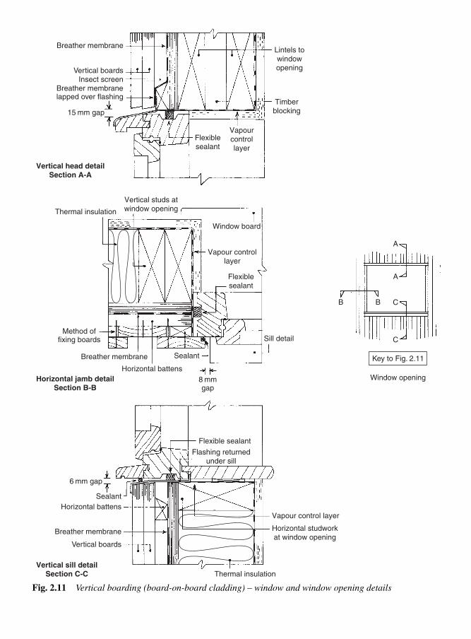
Breather membrane
Sealant
Vertical boards
Vertical boards
Horizontal battens
Horizontal battens
Breather membranelapped over flashing
Breather membrane
Breather membrane
Insect screen
15 mm gap
8 mmgap
6 mm gap
Flexiblesealant
Flexible sealant
Sealant
Vapourcontrollayer
Vapour controllayer
Vapour control layer
Timberblocking
Lintels towindowopening
Vertical studs atwindow opening
Horizontal studworkat window opening
Vertical head detailSection A-A
Horizontal jamb detailSection B-B
Vertical sill detailSection C-C
Sill detail
Window board
Flashing returnedunder sill
A
A
CBB
C
Thermal insulation
Method offixing boards
Key to Fig. 2.11
Window opening
Thermal insulation
Flexiblesealant
Fig. 2.11 Vertical boarding (board-on-board cladding) – window and window opening details

32 External cladding
Two stainless steel nails are used with each shingle to form a single
layer to include a double layer at the base for extra protection –
ferrous metal nails should not be used (see Volume 1, section 1.10.3g).
Joints must be staggered with a gap of 5 mm between each shingle to
allow for moisture movement (see Fig. 2.1e).
In the case of shakes, again the log is cut to the required lengths (simi-
lar to shingles), and quarter sawn (Fig. 2.12a).
However, before they can be tapered, the blocks are ‘split’ using a
cleaver (Fig. 2.12d) to produce a ‘rough’ cut finish. They are then taper
2.4.2 Shakes (Fig. 2.12f)
(b)
Blocks cut to formtapered shingles
(e)
Blocks cut to formtapered shakes
(c)
Sawn face(shingle)
(f)
Rough face(shake)
(a)
Length of shingleor shake
Shingle Shake
(d)
Shakes
Mallet
Cleaver
Machine cut Hand and machine cut shakes
Fig. 2.12 Producing shingles
and shakes

Plywood cladding 33
sawn (Fig. 2.12e) to produce a shake with the ‘rough’ face on the
outside (Fig. 2.12f).
Shakes are usually 100 to 355 mm in width and 610 mm long taper-
ing down to 4 mm.
2.4.2.1 Fixing
Similar to shingles, shakes are fixed by securing stainless steel nails
to horizontal grounds.
Plywood must have been manufactured for exterior use (see BS EN
636: 2003, Plywood specifications; WBP, see Vol. 1, section 4.1.2)
and should be not less than 9.5 mm thick. It may be used in strip form
(as weatherboard) or sheet (panel) form (Fig. 2.13b).
A typical corner detail of ply cladding is shown in Figs 2.13a and
2.13b together with a suitable corner cover lath.
Figure 2.13b shows how a vertical ply panel abutment can be formed –
edge exposure to the weather should always be reduced to a minimum.
Figure 2.14 shows detailing around a window opening. As with other
timber cladding, back-venting is a requirement – it can be achieved
in a similar way to solid timber cladding (see Fig. 2.6).
Nails used for fixing the cladding should be hot-dip galvanized or
corrosion-resistant, for example stainless steel, silicon bronze, or cop-
per. Aluminium nails are unsuitable when the timber has been treated
with certain wood preservatives.
2.5.1 Detailing
A
A
B
B
Joint cover lath
Sealant filled joint (movement gap)
False cover lath to produce a panel effect
External corner
Solid or built-up corner cover lath
Horizontal section A-A Horizontal section B-B
(a)(b)
Fig. 2.13 Vertical and corner
joints for plywood panels
2.5.2 Fixing plywoodcladding
2.5 Plywoodcladding
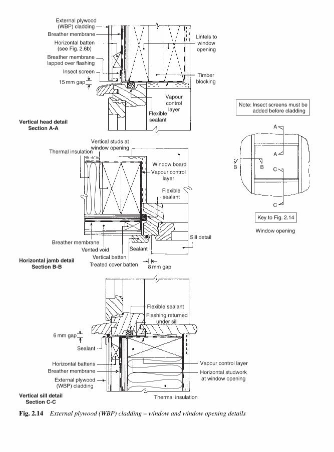
Vertical head detailSection A-A
Horizontal jamb detailSection B-B
External plywood(WBP) cladding
Horizontal battens
Breather membrane
6 mm gap
Flexible sealant
Sealant
Vapour control layer
Horizontal studworkat window opening
Vertical sill detailSection C-C
Flashing returnedunder sill
Thermal insulation
Breather membrane
Horizontal batten(see Fig. 2.6b)
Breather membranelapped over flashing
Insect screen
15 mm gap
Flexiblesealant
Vapourcontrollayer
Timberblocking
Lintels towindowopening
External plywood(WBP) cladding
A
A
CBB
C
Note: Insect screens must be added before cladding
Key to Fig. 2.14
Window opening
Vertical batten
Treated cover batten
Vented void
Breather membrane
8 mm gap
Flexiblesealant
Vapour controllayer
Vertical studs atwindow opening
Sill detail
Window board
Thermal insulation
Sealant
Fig. 2.14 External plywood (WBP) cladding – window and window opening details

Surface finishes to timber cladding 35
Where extra-good holding power is important, improved nails (Volume
1, Table 12.1) can be used. As a general guide, nails should have a
length of two and a half times the thickness of the board they are to
fix (annular-ring nails need only be twice this thickness).
Nails should be positioned as shown in Fig. 2.3, to help counter the
effect of moisture movement without the boards splitting. Face fix-
ing with round rustproof wire nails is common with weatherboard-
ing, board-and-batten, and board-on-board cladding. Matchboarding
can be secret nailed (the nail head being concealed by the groove in
the board) or fixed with proprietary metal clips, which are concealed
by the board that follows.
The use of timber preservatives requires proper safety precautions
when applying, as most are classified as inflammable and harmful. The
types in general use include organic-solvent and water-borne preser-
vatives (see Volume 1, section 3.3). As with a lot of materials they may
contain harmful chemicals, so it is advisable to consult the COSHH
regulations before use. Furthermore, there must be adequate ventila-
tion, the provision and use of personal protective equipment, and
strict following of the manufacturer’s instructions. (See BS 1282: 1999,
Wood preservatives. Guidance on choice, use and application.)
Surface finishes, i.e. paints, varnishes and woodstains can be classi-
fied as low to high build surface coatings. For example:
(i) Paint – High-build, will obscure the surface below making it
opaque.
(ii) Varnishes – High-build, allows the underlying surface to be
seen (transparent) and provide protection.
(iii) Woodstains – Low to High build, provide a coloured surface
finish which can be semi-transparent or opaque.
Low build – offers minimal surface protection.
Medium build – offers adequate protection.
Finishes can have decorative and weather-protective qualities, yet be
permeable to water vapour (micro-porous); that is to say, if water
vapour enters the wood from behind the cladding (most should be
vented away) or moisture enters via surface jointing, etc., it can escape
through the permeable (breather) surface. If an impermeable paint or
varnish film is used as outer surface protection and moisture enters
the wood via small cracks, etc., it could become trapped and cause a
breakdown of the surface film. Typical examples of film failures are
bubbling, flaking, and splitting paintwork. With clear varnishes, the
timber below could become discoloured with blue-stain fungi, etc.
2.6 Surfacefinishes to timbercladding

36 External cladding
Suitable micro-porous finishes can be grouped as:
(a) exterior emulsion paints;
(b) exterior wood stains;
(c) certain alkyd paints.
These are water-based acrylic paints producing an opaque coloured
‘silk’ finish. Application methods vary – some manufacturers may
specify two brush coats, others three. Surfaces may last as long as five
years without retreatment; however, this will depend greatly on the
amount and type of exposure, for example atmospheric pollution.
These have a water-repelling non-opaque (translucent) matt to semi-
gloss finish and are available in many light-fast colours. These stains
generally protect wood against blue-stain and mould growth. Appli-
cation usually involves a minimum of two brushed coats.
2.6.2 Exterior woodstains
Note: It would appear that both the above groups perform best when theyare applied to sawn timber (unplaned).
Although not generally associated with cladding, alkyd paints should
also be mentioned. These paints can be classified as:
(a) general-purpose alkyds – non-breather-type impermeable paints,
available in a high-gloss finish.
(b) exterior-quality alkyds – low-gloss paints with low permeability
(micro-porous), suitable for outside use but usually confined to
coating the outer surfaces of exterior joinery, i.e. doors, win-
dows, etc.
Plywood may be available as a pre-finished panel which has received
a heavy coating of synthetic resin – possibly covered with a layer of
white or coloured mineral chippings (see Volume 1, section 4.1.2).
Tempered hardboard, exterior-grade cement-bonded particle board, and
non-combustible boards (see Volume 1, Chapter 4) can all be fixed in
a similar way to plywood, i.e. on preservative-treated back battens.
Surface treatment will be similar to that for timber.
Plastics are usually used in the form of weatherboard, and available
in a variety of finishes including simulated timber, shown in Fig. 2.15,
together with fixing details. Corner and edge detailing usually involves
2.6.3 Alkyd paints
2.6.4 Plywood finishes
2.7 Othercladdings
2.6.1 Exterior emulsion paints

Other claddings 37
using special extruded sections supplied by the manufacturer of the
main profile.
Masonry – brickwork, stonework, and blockwork – is very popular as
a cladding to timber-framed houses. Masonry is attached to the load-
bearing timber structure by means of flexible metal ties that allow for
any differential movement between the dissimilar materials – examples
are shown in Chapter 1, Figs 1.7 and 1.9.
The use of cement rendering (see Table 2.1 and Fig. 2.1f) (a mixture of
sand, cement, and sometimes lime (or substitute), with water to make
a mortar) as a cladding relies on sheets of expanded metal stapled
across a framework of timber to key, hold, and reinforce the rendering
when set. These days, proprietary metal lath backings are available in
the form of galvanized welded wire mesh, reinforced with stainless
steel wire. A sheet of perforated absorbent stiff paper is incorporated
within the fabric, and a breather paper may also be included. The lath
is stapled with stainless steel staples every 150 mm to vertical preser-
vative-treated battens fixed at 400 mm to 600 mm centres. A ventilated
space of at least 25 mm deep should be left behind the rendering.
Timbergrounds
Extrudedprofiles
Plastics Cellularboxed section
Foam-filledsections
Fixing clip
Direct fixing
Fixing (tongue) clip
Interlocking detail
Note: Sections for edging and jointing internal and external angles are availableFig. 2.15 Plastics (uPVC)
weatherboarding

38 External cladding
References
BS 1282: 1999, Wood Preservatives. Guidance on choice use and
application.
BS 4072: 1999, Copper/Chromium/Arsenic – Preparations for wood
preservatives.
BS 4261: 1999, Wood Preservation, Vocabulary.
BS 5589: 1989, Code of practice for wood preservation.
BS 5268–5: 2005, Structural use of timber, code of practice for the
preservative treatment of structural timber.
BS 5707: 1997, Specification for preparations of wood preservatives
in organic solvents.
BS 5534: 2003, Code of practice for slating and tiling (including
shingles).
BS 476–3: 2004, Fire tests on building materials and structures.
Classification and method of test for external fire exposure to roofs.
BS 7956: 2000, Specification for primers for woodwork.
BS 6150: 2006, Code of practice for painting of buildings.
BS 476–7: 1997, Fire tests on building materials. Surface spread of
flames.
BS 8414–1: 2002, Fire performance of external cladding systems.
BS EN 634–2: 1997, Cement-bonded particle board, specification.
BS EN 633: 1994, Cement-bonded particle boards, definition.
BS EN 636: 2003, Plywood specifications, Fire safety: 2000.
Building Regulations Approved Document B1, Fire Spread: 2000.
Tile hangings – tiles or shingles – are lapped as roof tiles and double-
nailed to preservative-treated battens. Because the battens will be fixed
horizontally, notches may be cut or gaps left along their run – or counter
battens used as previously mentioned with vertical matchboard – to
allow for full back-venting of the cavity.
Metal cladding is usually available as a proprietary cladding system,
in which case manufacturers will supply all the necessary fixings and
fixing details.
The main purpose of a window is to allow natural light to enter a build-
ing yet still exclude wind, rain, and snow. Windows are also a means
of providing ventilation when the glazed area is made to open and
trickle vent (Fig. 3.64) within their frame. An openable ‘light’ (a single-
glazed unit of a window) is called a ‘casement’ or ‘sash’ – hence the
term ‘casement window’ or ‘sash window’.
Timber components of the window need to be profiled externally in
such a way as to prevent water penetrating the building through small
gaps by the process of capillarity (see section 3.1.2). Failure to do so
could result in a high moisture content of timber and its eventual
breakdown by moisture-seeking fungi, not to mention the many
other structural and environmental effects associated with dampness
(as featured in Volume 1, section 2).
Modern methods of window construction have mostly overcome this
problem by the introduction of various means of weathering to the
frame (Fig. 3.10).
Most building materials are porous (i.e. contain voids or pores), thus
allowing moisture to travel into or through them. Moisture may enter
these materials from any direction, even the underside, and travel
upwards as if defying the laws of gravity.
Upward movement of moisture is responsible for rising damp and is
caused by a force known as ‘capillary’ force, which in the presence
of surface tension produces an action called ‘capillarity’.
The microscopic molecules of which water is composed are of a
cohesive (uniting or sticking together) nature which, as a result of
Windows3
3.1 Windowprofiles
3.1.1 Surface tension(Fig. 3.1)

their pulling together, produces the apparent effect of a thin flexible
film on the surface of water. The effect is known as ‘surface tension’.
As can be seen in Fig. 3.1, the reluctance of this ‘skin’ to be broken
can be shown by filling a container with water just below its brim,
then slowly adding more water until a meniscus (curved surface of
liquid) has formed (Fig. 3.1a). Its elasticity can be demonstrated fur-
ther by carefully floating a small sewing needle on its surface. Figure
3.1b shows how a depression is made in the ‘skin’ by the weight of a
needle. If, however, surface tension is ‘broken’ by piercing the ‘skin’
the needle will sink.
A clear clean glass container partly filled with water will reveal a
concave meniscus where the water has been drawn up the sides of the
glass (Fig. 3.2a). This indicates that a state of adhesion (molecules
attachment of dissimilar materials) exists between the glass and water
molecules and at this point is stronger than the cohesive forces within
the water.
Figure 3.2b shows what happens when a series of clean glass tubes is
stood in a container of water. The water rises highest in the tube with
the smallest bore (hole size), indicating that the height reached by
capillarity is related to the surface area of water in the tube. It can there-
fore be said that, if the surface area of water is reduced or restricted,
the downward pull due to gravity will have less effect, whereas
upward movement will be encouraged by surface tension.
A similar experiment can be carried out by using two pieces of glass
as shown in Fig. 3.2c. This method produces a distinct meniscus
which can be varied by making the gap at the open end wider or nar-
rower. It should now be apparent that, for capillary force to function,
40 Windows
Water
Needle
(a)
(b)
WaterContainer
Meniscus
Fig. 3.1 The effect of surface
tension
3.1.2 Capillarity (Fig. 3.2)

all that is needed is water with its cohesive properties and a porus
material, or a situation providing close ‘wettable’ surfaces which
encourage adhesion.
Knowledge of how water acts in certain situations, and reacts towards
different materials, enables a building and its components to be
designed with built-in water and moisture checks. For example, the
common method of preventing moisture from rising from the ground
into the structure is by using a horizontal damp-proof course (DPC)
like those shown in Volume 2, Fig. 5.1. Penetrating damp has also
been avoided by leaving a cavity between outer and inner wall skins.
However, a vertical DPC would be used where both skins meet around
door and window openings.
There are many other places – particularly the narrow gaps left around
doors and sashes – which provide ideal conditions for capillary action
if preventative steps are not taken. The first line of defence should be
to redirect as much surface water away from these areas as possible,
by recessing them back from the face wall and encouraging water to
drip clear of the structure.
Figure 3.3 shows how a ‘throat’ (groove) cut into the underside of over-
hangs, i.e. thresholds, window sills, drip moulds, etc., interrupts the
flow of water by forcing it to collect in such a way that its increase in
weight results in the drip being formed. Further examples of throat-
ings are shown in Figs 3.6, 3.10, 3.15 and 3.16.
Window profiles 41
Adhesion
Water
Glass sheets
Packing
Gap
Elasticband
Tray of water
(a)
(c)
(b) Glass tubesFig. 3.2 The effect of capillarity
3.1.3 Preventativemeasures against theentry of moisture

It is inevitable that water will find its way around those narrow gaps,
so anti-capillary grooves, or similar, are used. Figure 3.4 shows how
these grooves work, and Fig. 3.6 illustrates how they are included in
window design.
Most standard windows are made from softwood, usually European
Redwood (pinus sylvesttis) or European whitewood (picea abies or
abies alba), both non-durable, which, at the manufacturing stage, is
treated with wood preservative before being coated with a wood
primer (base coat). The method of preservative treatment will depend
on the stage at which treatment is carried out; for example, after com-
ponents have been machined or at the assembled staged (see Volume 1
Chapter 3; also CP 153: part 2: 1970, Table 3).
Some hardwood timbers may also be used for extra durability, includ-
ing Idigbo (terminalia ivorensis), European Oak (quercus robur),
Meranti/Red Lauan (shorea spp), Sapele (entandrophragma cylin-
dricum) (see Volume 1, Table 1.15), and Brazilian Cedar (cedrela spp).
42 Windows
1st and 2nd Line of defence
Fig. 3.4 Anti-capillary grooves
Wettable source
Overhang
Arrangement at a window sill – head, weather board, etc.
Water collects
Drip
Throat
ClearanceFig. 3.3 Encouraging water
to drip
3.2 Types ofwindows

An opening light may operate in many different ways, for example, it
may be swung, tilted, turned, or slid; and in some cases it may combine
more than one of these operations to facilitate cleaning or draught
prevention. Figure 3.5 has been included to simplify identification.
Generally, the frame will consist of a head, jambs, and sill (or cill)
for a simple single-light casement window, but other types, such as
multi-light casement windows, include Transoms and Mullions (see
section 3.2.4).
The casement is constructed with a top rail, a pair of stiles and a bot-
tom rail – glazing bars may also be included to reduce the glazed area
as well as adding an aesthetic design to the window.
Types of windows 43
Side-hung
Top-hung Bottom-hung(opening inwards)
Vertical pivot
Horizontalpivot
Tilt and turn –side – and bottom –
hung (doubleaction –
inward opening)
Louvre Vertical sliding(double-hung)
(Projecting windows)
Verticalmoving axis
Horizontalmoving axis
Fig. 3.5 Diagrammatic method
of showing opening lights
3.2.1 Single-lightcasement windows

Figure 3.6 shows details of two types of casement windows:
● the obsolete ‘traditional’ type, which housed its casement fully
within its frame; and● the more modern ‘stormproof’ type which, because of its double-
rebate system, projects slightly outside the window frame – this is
brought about because both the frame and the casement are rebated –
thereby giving much better weather protection as a whole, and the
added benefit of increased natural light.
Because the rebate in the frame of the ‘stormproof’ type is only half
the casement width, direct glazing or deadlight (non-openable) can be
incorporated into the window frame without the need of a casement.
Construction methods will depend mainly on the type of window and
the sectional profile of its members. Traditional sections (and storm-
proof sections to BS 644: 2003, Timber windows) are shown in detail
in Fig. 3.6 (Fig. 3.10 shows how these sections can be modified). The
important feature of all these sections is how the grooves are formed
to provide protection against the entry of moisture by capillary action
(see Fig. 3.4).
44 Windows
Drip mould Stormproof type Traditional type (obsolete)
Weather seal
Casement(sash)
Top rail
Head
Jamb
Bottom rail
Sill (cill)
Sub-sill
Height Height
Plan
Sash stile
Frame
Fig. 3.6 Sectional details of single-light casement windows
3.2.2 Construction

Window frames should be held together at the corners with either
combed joints (multiple corner bridles) with not less than two tongues,
or mortise-and-tenon joints. The tongues or tenons should not be less
than 12 mm in thickness. Where horns are required for building-in pur-
poses, they should not be less than 40 mm in length. Joints should be
glued, with a suitable synthetic adhesive, and be held together with
wedges and/or pegged with hardwood or metal star dowels (Fig. 3.7).
Casements should be joined by using combed or mortise-and-tenon
joints, glued (as above), and pegged and/or wedged (depending on
the type – bridle joints cannot be wedged). Traditional casement
joints are shown in Fig. 3.7. Stormproof casements details are shown
in Fig. 3.12.
Types of windows 45
Width reduced for haunch – possiblearea of weakness (top and bottom joints)
when wedging the joint
Portion of mould (ovalo) cutaway – square to rebate depth Franked (reverse)
haunch
Top rail
Top rail
Top railTop rail
StilesBottom
rail
Hardwood ormetal (star) dowel
Stoppedscribe Stopped
scribe
Sash stile
Sash stile
Sash stile
Wedging approx.slope 1 in 10
(a) Hand scribed and haunched mortise- and-tenon joints
Bottom sash rail Bottom sash rail
(b) Hand scribed and franked (reverse haunch) mortise-and-tenon joints
A
B B
A A-A
B-B
Fig. 3.7 Joints using traditional
sash stile and sash rail
Note:1. The term ‘sash’ stile or rail is derived from the wood sectional profile
used to make up sashes for sash windows (see section 3.2.8). The samewood sections, however, are used to construct traditional casements.
2. Mortise-and-tenon joints: the use of a ‘franked’ haunch (as shown indetail ‘b’) on shallow rebate/moulded small sectioned stock reduces therisk of splitting the stile during wedging and can produce a stronger joint

Sashes can be hung in one of the three ways shown in Fig. 3.8, where
the V indicates the hinging side and that the knuckle (Fig. 3.58) of
the hinge is to that face. (Three different types of hinge are shown in
Fig. 3.58, together with their respective fixing details.)
The screws used to fix hinges will be exposed to varying amounts of
strain, particularly those used on the top hinges on side-hung sashes,
and those on sashes which are top hung, which will constantly be
subjected to withdrawal.
Because openable casements must provide varying amounts of ven-
tilation a multi-positioned casement stay similar to the one shown in
Fig. 3.58 is used. This also gives a means of securing the sash when
closed. Side-hung casements also use a window fastener (Fig. 3.58)
fixed midway to the closing side stile and jamb.
Glass is not usually fixed until the window is built into the structure,
but its weight must be taken into account with regard to hinge and
screw sizes. The glass also plays an important part in holding the
casement square (with regard to setting blocks see the section on
glazing – section 3.8).
Introducing more than one light into a window frame will mean its
division by other members, namely mullions (intermediate vertical
members) and/or transoms (intermediate horizontal members). The
possible combinations are many and vary according to the number
and size of lights and whether they are openable or dead. Figure 3.9
shows how they may appear, but to fully appreciate all the possibilities,
including combination with door frames, manufacturers’ catalogues
should be consulted.
46 Windows
Interior
H H
H H
Anticlockwiseclosing(ACW)
Clockwiseclosing(CW)
H � Hinge Exterior
H
H
H H
ACW side-hung CW side-hung Top-hung
H
H
Fig. 3.8 Opening casements
3.2.4 Multi-lightstandard (stormproof)casement windows
3.2.3 Hanging openingcasements

Figure 3.10 shows joint locations and section details of a standard
three-light casement window. Provision has been made for a resilient
weather-strip within the casement rebate of the frame. Window
frame joints for this type of window (Fig. 3.11) are usually made
with a mortise and tenon – glued, wedged, and/or pinned through the
tenon from the inside face of the frame with metal or wood dowel.
For reasons of economy, some manufacturers use scribed butt joints
held together with glue and screws in place of the mortise and tenon.
Casement joints between rails and stiles are combed joints, glued and
pinned with metal or wood dowel from the inside face of the case-
ment. Generally the faces of the casement would reveal the stiles run-
ning the full height of the casement opening, with the rails butting up
Types of windows 47
Two lights Three lights Four lights
Head
Transom
TransomJamb
Sill
Five lights Six lights
Dead light
Casement
Sub-light
Mullion
Jamb
Waist rail – window – door frame(combination windows)
Vent light
Fig. 3.9 Variations in casement
window design
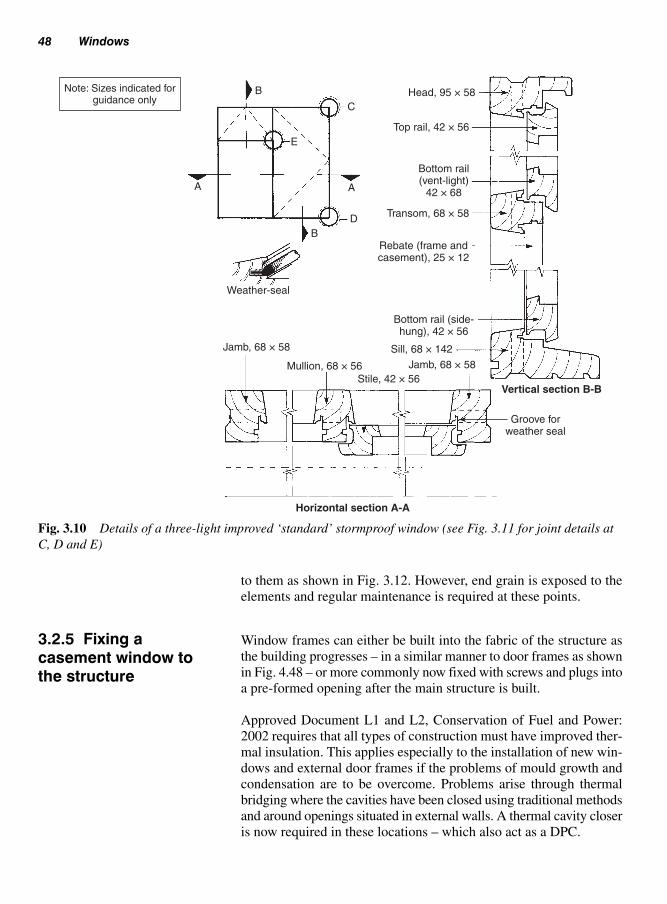
to them as shown in Fig. 3.12. However, end grain is exposed to the
elements and regular maintenance is required at these points.
Window frames can either be built into the fabric of the structure as
the building progresses – in a similar manner to door frames as shown
in Fig. 4.48 – or more commonly now fixed with screws and plugs into
a pre-formed opening after the main structure is built.
Approved Document L1 and L2, Conservation of Fuel and Power:
2002 requires that all types of construction must have improved ther-
mal insulation. This applies especially to the installation of new win-
dows and external door frames if the problems of mould growth and
condensation are to be overcome. Problems arise through thermal
bridging where the cavities have been closed using traditional methods
and around openings situated in external walls. A thermal cavity closer
is now required in these locations – which also act as a DPC.
48 Windows
Head, 95 × 58
Rebate (frame andcasement), 25 × 12
Bottom rail (side-hung), 42 × 56
Sill, 68 × 142
Stile, 42 × 56
Mullion, 68 × 56
Jamb, 68 × 58
A
B
A
D
Jamb, 68 × 58
Weather-seal
Vertical section B-B
Horizontal section A-A
C
B
Groove forweather seal
Note: Sizes indicated for guidance only
E
Transom, 68 × 58
Bottom rail(vent-light)
42 × 68
Top rail, 42 × 56
Fig. 3.10 Details of a three-light improved ‘standard’ stormproof window (see Fig. 3.11 for joint details at
C, D and E)
3.2.5 Fixing acasement window tothe structure

Types of windows 49
Star dowel
End-grain exposure
Stile
Top rail
Top rail
Bottom rail
Generally accepted arrangement
Fig. 3.12 Casement corner-joint
(combed) arrangements
Horn
Joint about C
Joint about E
Joint about D
Horn and possiblecut-back line
(outside of wall reveal)
Note: See Fig. 3.10 for joint locations of c, d and e
Fig. 3.11 Window frame joints
(see Fig. 3.10)

Thermal cavity closers are available from proprietary manufacturers
in a variety of shapes and sizes to fit any situation. Figure 3.13 shows
a vertical section of how a typical window is incorporated into the main
outer fabric of the house.
A bay is an integral part of a building that projects outwards beyond
the main building line. It may be square, rectangular, splayed, or seg-
mental in plan, and it may extend one or more storeys above the ground.
If only the window itself projects, without any substructure to ground
level, it is called an ‘oriel’ window. Bay windows are built from a num-
ber of standard or high-performance windows joined together at their
corners to produce the following named types:
(a) Square bays (sometimes called 90° bays) (Fig. 3.14a): the fronts
of these bays, unlike the ends, are often made up of more than one
frame. Bay corners (angular mullions) may be constructed by one
of three methods:
(i) a solid corner post (traditional);
(ii) a mitred section with either an inset fillet (tongue) or a face
cover;
(iii) a solid corner infill.
50 Windows
Win
dow
heig
ht
A
B
A Front elevation
Window board
Thermal insulation
inside lintel
Steel lintel to suit span/load
Plaster
Head
B
Windowboard
Plaster
Vertical section A-A
Thermal insulationThermal cavity closer
Face brickwork
Sealant
Fixings
Window width
Horizontal section B-B
Sill
Block work
Fig. 3.13 Window installation details
3.2.6 Casement baywindows

(b) Splayed bays (Fig. 3.14b): these have a similar construction to
square bays, except that the sides are splayed – usually to an angle
of 45° or 60°.
(c) Segmental bays (Fig. 3.14c): each bay segment may be made
up of three to seven window frames to make further segmental
subdivisions.
Types of windows 51
Vertical DPC
(a) Square bay
(b) Splayed bay
Gasket
Gasket-sealed infillCorner infill Tongue
Solid ortonguejointed
Sill mitre –glued and dowelled,
with or withouthandrail bolt
(see Vol.1, Fig. 12.11)
(c) Segmental bay
Vertical DPC nailed intoback (mortar key) groove
60°
120° 135°
45°
Birdsmouthed jambDPC
nailedto jamb
Mullions – solid or tongued
Note: Thermal insulation not shownFig. 3.14 Bay window shapes
and corner construction

These frames usually have a curved sill, which is why this type of bay
is sometimes known as either a ‘circular’ or a ‘shallow circular’ bay.
Figure 3.14 also shows how these bays meet up with wall reveals.
For the purpose of this chapter, an energy-saving type of window is one
which obtains its efficiency from an ‘all-round’ draught- and weather-
seal and has the capability of being glazed with a sealed double-glazed
unit of a total thickness not exceeding 24 mm, as shown in Fig. 3.15,
unless a stepped-edge type is used (Fig. 3.49).
Figure 3.16 shows member details of a high-performance window.
Most of these windows are in hardwood. Some models may have built-
in ventilation in the form of a duct mortised into the top rail of the case-
ment, which can be regulated from inside the building (Fig. 3.64).
Casement rebates often accommodate sealed double-glazed units of up
to 24 mm thickness. Special sliding hinges (friction-stay types) permit
easy cleaning from inside the building – details of these hinges and
special latching and locking mechanisms are shown in Figs 3.59, 3.62,
and 3.63.
The term ‘high-performance window’ can be misleading, but generally
means a window which has one or more energy-saving feature within
its design, such as weather-seals, thermal insulation, and ‘Low E’ glaz-
ing (see section 3.5). Many have integral ventilation and security fas-
teners. Most have a type of hinge mechanism which enables openable
lights to be cleaned from inside the building.
High-performance windows are generally made from a hardwood or
from the softwood Douglas fir (Pseudotsuga menziesii) – both should
be moderately durable. The former may be better and, provided sap-
wood is excluded, preservative treatment may be optional. However,
selected European redwood (Pinussylvestris), which is non-durable,
may be used, in which case preservative treatment would be necessary.
Firstly, let us differentiate between a sash window and a casement
window. Both are designed to house the glazing, but opening case-
ments are hinged, whereas sashes slide open.
Double-hung sash windows consist of two vertical sliding sashes,
one offset above the other. Both sashes are counterbalanced at each
side either by a weight, suspended by a line (cord or chain), or by a
spring balance mechanism (see section 3.2.14). Figure 3.17 shows
the basic principle of using a weight to counterbalance the weight of
the sash and its glass.
52 Windows
3.2.7 High-performance casementwindows
Note: The design principles whichfollow also apply to top-hungcasements, but vent lights gener-ally occur only within the frame-work of energy-saving types.
3.2.8 Double-hungsash windows

There are two main types of window: the traditional cased windows
with ‘cased’ or ‘boxed’ frames (the case houses the weights), and the
more modern types which have ‘solid’ frames with a spiral spring bal-
ance either attached or housed in them.
Types of windows 53
Combed joint
Weather-moulding – drip
Head
Top rail
Glazing-bead
Weather-seal
Double-glazedsealed unit
Window board
Bottom rail
Sill
Sub-sillLine of facebrickwork
Note: Trickle vent not shown
Note: Sectional sizes vary according to styles
Fig. 3.15 Energy-saving casement window

Head, 90 × 58
Weather-seal
Ventilator, mortisedthrough top rail – night
ventilation (see Fig. 3.64)
Double-glazedsealed unit
Bottom rail, 55 × 68
Sill, 90 × 68
Window board
Sub-sill
Note: Sectional sizes vary according to styles
Fig. 3.16 High-performance casement window
Single sash Double-hungsash window
Edge view
Outside
Note: When closed, front sash to top and in front of bottom sash (viewed from outside)
Sash up
Sash down
Fig. 3.17 Counterbalancing sashes with weights

Figures 3.18 and 3.19 show the arrangement of components and how
they are assembled and joined together. Pulley stiles are trenched
into the head and sill and back-wedged within the sill housing. The
inner and outer linings are grooved, to receive the tongues cut into
the edges of the pulley stiles and head. Right-angle joints between
the head and linings are stiffened with glue blocks.
Detachable ‘pockets’ are cut into both pulley stiles (Fig. 3.20) to allow
access to the weights and sash lines. Two pulley wheels are mortised
Types of windows 55
Inside liningA Parting slip
Glue blockNail
Head
Horn
Horn
Meeting rails(splayed rebate)
Draught-board
Putty pointing
Glass
GlassB
Sill
Vertical section A-A
Inner lining
Back lining (ext. ply)
Sash cord
Detachable pocket
Parting slip (mid-feather/wagtail)
Weight
Pulley stile
Outer lining
Parting bead
Part elevation
Horizontal section B
A
Bead
Pulley (Fig. 3.65)mortised and housed
into pulley stile
Fig. 3.18 Part double-hung
sash window with cased frame
3.2.9 Cased frames

into each stile, with their centres not more than 115 mm or less than
90 mm from the head.
The sashes are held in check by the linings on the outer side and by
the bead on the inner. At sill level, an upstand (draught-bead) may be
incorporated in the design, which should (theoretically) allow a gap
to be left between meeting rails for ventilation purposes without cre-
ating a draught at sill height. Sashes are held apart with parting bead,
which is housed into both pulley stiles and the head.
56 Windows
Inner lining
Glue block
Glue block
Nail (pivot)
Parting slip(mid-feather/
wagtail)
Back lining(plywood)
Pulley-stile pocket(hidden detail)
Wedge
Throating
Outer lining andparting bead cut away
to prevent water lodging
Sill
Outer lining
Outer lining(head)
Pulley-stiletongue
Glue block
Mortise holefor pulley
(see Figs 3.18and 3.65)
Head
Pulley stile
Fig. 3.19 Sectional
constructional cut-away details
of a cased frame

Although some are left open, the back of the cased frame should be
lined with exterior-quality plywood to prevent mortar droppings, dust,
etc. from entering the box and restricting the distance the weight can
travel. (If the top-sash weight were not allowed to drop its full distance,
the sash would not close.)
A parting slip (or ‘wagtail’ or ‘mid-feather’) should be mortised
through the head of each side and held up with a peg or nail, which
allows it to swing freely (its purpose is to separate the weights). On
tall windows, weights tend to swing when the sashes are being
opened – the parting slip prevents the weights from touching one
another.
Figure 3.21 shows vertical and horizontal sections through the frame
and sashes. Alternative methods of housing the spiral spring balances
are also shown in Fig. 3.24.
Joints between jambs, head, and sill may be combed-jointed or
mortised-and-tenoned. Outer linings are nailed and glued to the jambs
Types of windows 57
Saw cut (kerf)
Saw cut (kerf)
Section B-B(Pulley stile)
Section A-A(Pulley stile)
Enlargedalternative at X
Split with the grainA
Tongueremoved
BB
X
A
Fig. 3.20 Forming a detachable
3.2.10 Solid frames

and head. Parting beads may incorporate a form of weather-seal, and
staff beads are sometimes omitted to allow the sashes to tilt inwards
for easy cleaning and to be removed from their frames for maintenance
purposes, i.e. painting, etc. Some proprietary solid-framed sash win-
dows are categorized as having high performance – because of the
facilities already mentioned and their ability to accept sealed double-
glazed units.
58 Windows
Extended outer lining
Combed joint
Head
Parting bead(flexible
weather-seal)
Spiral balancespring
Sash fastener(see Fig. 3.66)
Meeting rails(weather-sealed)
Bead – screwedand cupped
Bottom rail(weather-sealed)
Draught – board
Window board
Front elevation
Sash stile
Built-up pulley stile(plastics or metal insert)
Solid pulley stile Solid pulley stile
Sill
Vertical section A-A
Glass
Alternative arrangements about B
Parting bead/flexible weather-seal
A
A
B
Double-glazed sealed unit
Weather-sealSpiral balance spring
Fig. 3.21 Double-hung sash
window with solid frame

Corners are scribed, with either a combed joint (Fig. 3.12) or a mor-
tise-and tenon joint (Fig. 3.22a). Through tenons may be used where
horns are to be retained, otherwise a haunch should be used. Where
the backs of stiles are grooved to receive cords or a spring balance, a
franked haunch (see Fig. 3.22a) – also known as a ‘reverse haunch’ –
should be used, otherwise the small amount of wood left between the
Types of windows 59
Machine scribe(through)
Hand scribe(stopped)
Franked (reverse) haunch
(a)
Mortise-and-tenonmeeting rail (e)
Cross-halving(mitred)
Dovetailed bridle(b)
Bridle
Stile
Meeting rail
(d)
Cross-halving(scribed)
Glazing bar –(vertical)*
Glazing bar –(horizontal)*
Horn
Mortise-and-tenon(through)
(c)
a
d/e
c
b
Front elevation
Through-glazing bars*(for mortise-and-tenon
joints)
Key to Fig. 3.22* Through-glazing bars to run theshortest distance of the fully glazedopening – be it vertical or horizontal
Stub-tenon (f)
Fig. 3.22 Traditional sash joints
3.2.11 Sashes
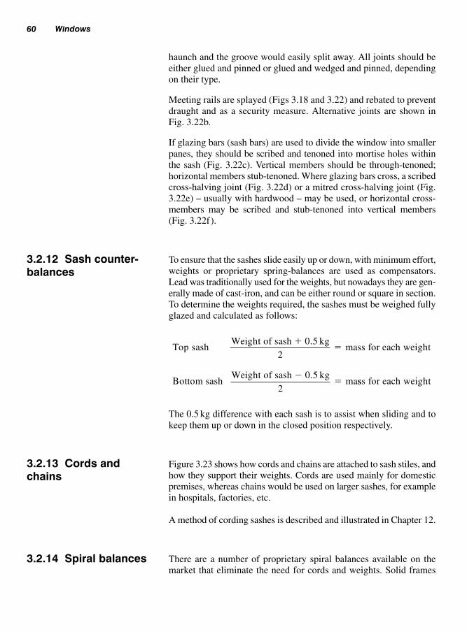
haunch and the groove would easily split away. All joints should be
either glued and pinned or glued and wedged and pinned, depending
on their type.
Meeting rails are splayed (Figs 3.18 and 3.22) and rebated to prevent
draught and as a security measure. Alternative joints are shown in
Fig. 3.22b.
If glazing bars (sash bars) are used to divide the window into smaller
panes, they should be scribed and tenoned into mortise holes within
the sash (Fig. 3.22c). Vertical members should be through-tenoned;
horizontal members stub-tenoned. Where glazing bars cross, a scribed
cross-halving joint (Fig. 3.22d) or a mitred cross-halving joint (Fig.
3.22e) – usually with hardwood – may be used, or horizontal cross-
members may be scribed and stub-tenoned into vertical members
(Fig. 3.22f).
To ensure that the sashes slide easily up or down, with minimum effort,
weights or proprietary spring-balances are used as compensators.
Lead was traditionally used for the weights, but nowadays they are gen-
erally made of cast-iron, and can be either round or square in section.
To determine the weights required, the sashes must be weighed fully
glazed and calculated as follows:
The 0.5 kg difference with each sash is to assist when sliding and to
keep them up or down in the closed position respectively.
Figure 3.23 shows how cords and chains are attached to sash stiles, and
how they support their weights. Cords are used mainly for domestic
premises, whereas chains would be used on larger sashes, for example
in hospitals, factories, etc.
A method of cording sashes is described and illustrated in Chapter 12.
There are a number of proprietary spiral balances available on the
market that eliminate the need for cords and weights. Solid frames
Top sashWeight of sash 0.5 kg
2mass for each
�� weight
Bottom sashWeight of sash 0.5 kg
2ma
�� sss for each weight
60 Windows
3.2.12 Sash counter-balances
3.2.13 Cords andchains
3.2.14 Spiral balances

are used to support the sashes (see section 3.2.10) to include a groove
that is run either on the edge of the sashes or in the solid frame to
accommodate the spiral spring (see Fig. 3.24a and b).
Figure 3.24 shows the sequence and procedures involved when fit-
ting a ‘balanceuk’ spiral balance.
Regular cleaning and maintenance of the spiral rod with a light oil is
recommended to improve the operating action of the spring. Other
points to consider when fitting a spiral balance are not to:
● bend the spiral rod;● forget to fit the limit stop;
Types of windows 61
Sash cord
150 m
in.
Knot
Knot
Weights
Sash nail (tack) –not clout nail
Chain
Inset pivotbar
Sash plateand bar
Washer andsplit-pin
connector
Boltconnector
Loopconnector
Knot
Sash stile
Fig. 3.23 Methods of attaching
cords and chains to sashes and
sash weights
Note: Consult fixing instructionswhen fitting this type of spiral balance.

● use the wrong spiral rod for the weight of sash;● tension more than necessary;● tension before glazing.
With the possible exception of some types of louvred windows, win-
dows made of steel and aluminium alloys are now generally fixed
direct to masonry without a timber subframe, which in the case of
aluminium-alloy windows was formerly thought necessary to avoid
62 Windows
3.3 Metalcasement inwood surround
16 mm
16 mm
16 mm
16 mm17 mm
(a) (b)
(c) (d)
Pulley stile
Spiral balance may be fitted into the sash stile (a) or pulley stile (b)
Top sash (c) and bottom sash (d) prepared to receive the foot of the spiral balance
56 mm
58 mm
11 mm
(e) Inserting the spiral balance(f) Securing the top of the spiral balance
Fig. 3.24 Installing a ‘balanceuk’ sash balance

direct contact with the alkaline components of mortar and concrete
(especially when damp). However, with the use of modern gaskets
and sealants (chalking agents) the adverse reactions, which were pre-
viously expected, now seem to be avoided.
Because of the slenderness of the metal profiles of domestic types of
window, the use of timber as a subframe is still popular. Wood species
such as oak, sweet chestnut, western red cedar, and Douglas fir may,
because of their acid content (particularly when damp), attack or react
with steel. A subframe made from timber from these species should
therefore either be sealed or have a gasket positioned between it and
any metalwork.
Metal casement in wood surround 63
(g) (h)
(i) Fixing travel stops
Securing foot of spiral balance to base oftop sash (g) and bottom sash (h)
(j) Adjusting tension on the spiral balance using tensioning hook (supplied)
Top travel stop
Top sash
25 mm
100 mm
Bottom travel stop
Fig. 3.24 (Continued)
3.3.1 Metal casementwindows
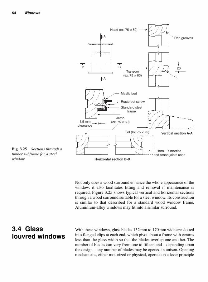
Not only does a wood surround enhance the whole appearance of the
window, it also facilitates fitting and removal if maintenance is
required. Figure 3.25 shows typical vertical and horizontal sections
through a wood surround suitable for a steel window. Its construction
is similar to that described for a standard wood window frame.
Aluminium-alloy windows may fit into a similar surround.
With these windows, glass blades 152 mm to 170 mm wide are slotted
into flanged clips at each end, which pivot about a frame with centres
less than the glass width so that the blades overlap one another. The
number of blades can vary from one to fifteen and – depending upon
the design – any number of blades may be opened in unison. Opening
mechanisms, either motorized or physical, operate on a lever principle
64 Windows
3.4 Glasslouvred windows
Head (ex. 75 × 50)
Drip grooves
Transom(ex. 75 × 63)
BP
A
A
Mastic bed
Rustproof screw
Standard steelframe
Sill (ex. 75 × 75) Vertical section A-A
Horn – if mortise-and-tenon joints used
Horizontal section B-B
1.5 mmclearance
20
Jamb(ex. 75 × 50)
Fig. 3.25 Sections through a
timber subframe for a steel
window

with coupled linkages. The operating handles (levers) are ‘handed’
(right-hand or left-hand) on the drive side of the frame, and the opposite
side houses a following device.
The metal framework and flanged louvre clips may be made of gal-
vanized steel or aluminium alloy. Flanged clips may also be made of
plastics.
Figure 3.26 shows three possible louvre arrangements – configur-
ations of both louvred and fixed lights are numerous.
Figure 3.27 shows how the ‘Naco de luxe’ louvred window is fitted
and fixed.
1. The framework must be square (diagonals equal) and have a min-
imum width of 50 mm, at least 50 mm of which must be flat and
square with its outer face.
2. Check for plumb and twist.
3. Position the operating channel plumb tight down on to the
square sill.
4. Loosely fix the operating channel, then the non-operating channel
in line with it.
5. Insert the PVC channel seal between the channel and the timber
surround (see (a)), then tighten the screws.
6. Cut the head and sill weather-bars to fit between the channels.
7. Fix the weather-bars between the channels. The heel of the head
weather-bar aligns with the inner face of the channels (see (b)).
Use a non-setting mastic to seal the ends of the weather-bars and
the underside of the sill weather-bar. Point the outside of the head
weather-bar.
8. Insert glass blades as per the manufacturer’s instructions. When the
louvre window is closed, blades should touch each other through-
out their length, and the upper and lower blades should touch the
flexible PVC weather-tongue.
Glass louvred windows 65
Fully louvred Top-louvred, transom rail,and fixed light
Louvred withfixed lightFig. 3.26 Glass louvred windows

Figure 3.28 shows a fully louvred ‘weatherbeta’ works-assembled and
sealed aluminium window.
Figure 3.29 shows how it could be fitted and fixed to a timber
subframe.
With more emphasis being made to energy-efficient construction,
timber may be substituted for the use of PVCu as a material for the
construction of windows. However, we should mention here what is
involved when manufacturing PVCu windows including possible pol-
lutants in the air during manufacture, as opposed to timber, which is a
renewable source of material.
66 Windows
50 mm
Head weather-bar
Insid
e
Openin
g h
eig
ht
Sill weather-bar(b)
(a)
Channel jamb
Inside
PVC channel seal
1 5
2
3 7
6
4 8Fig. 3.27 Fitting a ‘naco de
luxe’ louvred window
3.5 PVCu(Polyvinylchlorideunplasticised)windows

PVCu (polyvinyl chloride unplasticised) windows 67
Head
38 mm × 8 cskfixing screw
57 mm × 8 cskfixing screw
25 mm × 8 rd headFixing screw
Mastic bed
Weather-seal
Glass louvre blade
Jamb Mastic bedWeather-seal
Sill clip
Blade holder
Sill
Fig. 3.28 Fully louvred ‘naco
weatherbeta’ sealed window
Fig. 3.29 Louvred-window fixing
details to a timber subframe

PVCu window profile is a multi-chambered material, extruded usu-
ally with a bright white finish conforming to BS 7413: 2002 – other
finishes are available.
Various window designs are available which are similar in style to
the more traditional timber windows, as shown in Fig. 3.9, but incor-
porate, as standard, all the requirements necessary for PVCu to be
energy efficient.
The example shown in Fig. 3.30 has sliding sashes supported on
precision-made spring balances and includes 24 mm ‘Low E’ (Low
Emissivity) glazing units, which is the term used to describe glass
that has been treated with a surface coating which allows the sun’s
rays through, but reflects any heat back into the room.
Sashes, including those of timber construction, can be tilted inwards
for maintenance, as well as allowing the glass to be cleaned
(Fig. 3.31).
Window frames are usually fixed into the wall structure in one of
three ways:
(i) being built in as the wall is being built (Fig. 3.32);
(ii) inserting wall plugs and screws into a pre-formed opening
(Fig. 3.33b);
68 Windows
Fig. 3.30 Typical PVCu window
Note: Approved Document F,Means of ventilation 2002,requires that all types of windowsinclude a method of ventilationwithin the design of the window.
3.6 Fixingwindow frames

(iii) fixing into pre-formed rebated reveals, for example double-hung
cased windows Fig. 3.33d.
As shown in Fig. 3.32a, once the walls have reached sill height, win-
dow frames are positioned and held plumb by means of an anchored
stay and rail at the head (hooked over the window head) ready to be
walled in as brickwork progresses.
An arrangement of how a head and sill for a standard casement win-
dow may fit into the wall is shown in Fig. 3.32. Figure 3.32b shows
how a vertical DPC (which must run the full height of the window) is
attached to the back of the jambs with galvanized clout nails and is
sandwiched between the outer wall leaf and the cavity closer. (Direct
contact between an outer and inner wall leaf is not permitted without
an intervening DPC – otherwise, moisture might be allowed to travel
freely from the outer surface of porous brick or blockwork to the
inner plasterwork. This is often a problem with older houses where
vertical DPCs have been omitted.)
The methods of keying the sill and head horns, and providing mid-jamb
anchorage into the wall, are similar to those used with door frames (see
Chapter 4, Figs 4.5, 4.6).
All outside joints (small gaps) between the window frame and the
wall must be sealed. Traditionally, these joints were made good and
weathertight with a mixture of red mastic and boiled linseed oil, mixed
to a stiff consistency, then applied with a narrow pointing trowel to
form an angled fillet.
Fixing window frames 69
Fig. 3.31 Tilting the sashes for
maintenance and cleaning
3.6.1 Built-in windowframes

However, nowadays, modern sealants are available for most situations
(see section 3.10); they are supplied in cartridge form and fit into a
dispensing gun.
This method of installation is ideal for windows such as high-
performance types and those made of polished hardwood that may be
put at risk during the early stages of construction.
As shown in Fig. 3.33a, openings are formed by the bricklayer or mason
with the aid of a removable template (profile) (see section 3.6.3) made
to suit the window opening (size of window frame plus a fitting clear-
ance of not less than 3 mm all round). To facilitate removal once the
mortar has set, the profile should be allowed to reach a high moisture
content before being built-in – on drying, subsequent shrinkage should
then aid its removal. Planed (wrot) timber should be used for construc-
tion of the opening. Alternatively, for awkward and small openings, the
70 Windows
Nail
Stay
Spirit-level
Temporary support
Frame cramp
Frame cramp
Frame cramp
Horn – sill andhead (built-in)
Horn
AA
Built-in(a)
Vertical DPC
Rebate for sealantSub-sill
Horn cut back(splayed)
DPC nailed(galvanized clout nails)
to jamb(b) Horizontal section A-A
Fig. 3.32 Fixing a built-in
window frame
3.6.2 Non-built-inwindow frames

top and bottom rails of the profile itself can be made detachable (see
Chapter 4, Fig. 4.65) – the sides can then be easily withdrawn.
Propping and positioning profiles is the same as if window frames
were being built-in. Unless they are required elsewhere, profiles can
remain in position until it is safe to fit the windows. Covering the pro-
files with polythene will offer temporary weather protection to the
inner structure.
Fixing window frames 71
Spirit-levelStays
Temporary support towindow profile
(a) Profile removed Window installed
(See Fig. 3.34)
(b)
Plywood web
Metal lugThrough fixing via
plastics plug
Section A-A
(c) (d)
Metal bracketFolding wedges
Fixing bracket
Cased frame in check – wedgedand/or fixing brackets
Frame in-check – throughfixing or metal lugs
A
Clearance
A
Fig. 3.33 Fixing a non-built-in
window frame

Cased frames of double-hung sash windows (Fig. 3.33d) are simi-
larly positioned in check (see Fig. 3.33c) restricts window opening
by forming a masonry rebate – mainly for two reasons: to slim down
the appearance of the outer linings and, as with all rebated reveals, to
provide a good weather-seal. The window is fixed in position with
folding wedges driven between the reveals and the cased sides (in
line with the head and sill). Skewed nails into plugs or steel angle
brackets may also be used. Architraves are nailed to the inside linings
(sides and head) and to the inside face wall via wood plugs or pallets
to cover the main wedged fixings.
Joints between the framework and the outer wall are sealed as previ-
ously mentioned for built-in window frames.
To aid the bricklayer when forming the openings for windows, tim-
ber templates of the window profile (Fig. 3.33) are constructed from
72 Windows
Fig. 3.34 ‘Fischer’ frame-fixing devices
3.6.3 Profiled openings

planed timber, which are made in such a way as to be easily removed
without damage to the surrounding brickwork, see section 3.6.2. These
need to be made solid, square and braced as they may be used further
elsewhere on the site.
Figure 3.33b shows how jambs may be fixed with a flush reveal, using
the type of fixings shown in Fig. 3.34. The plastics plug and sleeve
are as one, and the whole assembly comes complete with a matching
screw and provision for capping the screw head if the fixing is made
through the jamb’s rebate.
If the reveal is rebated, and thereby providing a positive outward
window check as shown in Fig. 3.33c, inward movement may be
checked by:
(a) plastics plugs and screws through the jamb;
(b) steel fixing plates, used as fixing lugs, screwed to plugged
reveals.
As more and more people make use of their loft/attic space there has
been an increase in loft conversions. Planning permission is required
by the local authority if the area to be converted is to be ‘habitable’,
i.e. extra bedroom or study, etc., which may also include ‘en suite’
facilities.
However, consideration must be given to means of access to the
room by a staircase, which may mean the loss of valuable space from
the floor below.
If the loft space is not to be used as a habitable area and a window is
required just to provide light then planning permission is generally
not required as long as the window is fitted in line with the pitch of
the roof (Fig. 3.35) and does not effect the elevation. However, clar-
ification from the local planning office must be sought before pro-
ceeding as required for a dormer window.
Many proprietary types of windows are available where the opening
casement may be top-hung (Fig. 3.35) (recommended on lower
pitched roofs) or pivot-hung (Fig. 3.36).
However, for a ‘habital’ room, the window must be of a certain design,
by law, in order to act as a means of escape in an emergency – consult
the window manufacturer.
Fitting of the window may be carried out from the inside of the roof
space thus eliminating the necessity for a scaffold to be erected.
Skylights (roof window) 73
3.6.4 Direct fixing
3.7 Skylights(roof window)
Note: Consultation with a reputablebuilding contractor together withan architect or buildingsurveyor/designer who will drawup the plans and carry out all thenecessary alterations is advisable.
Note: Provision must be made toprevent any loose items fallingfrom the roof to the ground, whilstwork is being undertaken.

Before proceeding with any alterations to the roof, a risk assessment
conforming to H&S regulations must be carried out before the work
commences. This includes the area at ground level to be fenced-off
with warning signs indicating workings above.
The installation procedure generally follows as:
1. install a solid floor inside the roof space;
2. remove the sarking felt (or underslating felt), if fitted;
74 Windows
Fig. 3.36 ‘Velux’ pivot-hung
skylight
Fig. 3.35 Top-hung
skylights
3.7.1 Installation

3. remove the roof tiles to form an opening in the roof which is
large enough to be trimmed out (see Volume 2, section 8.9 Roof
openings) to suit the new window (truss rafters must not be cut);
4. cut the tile battens;
5. secure a suitable batten across the rafter/s to be cut, which is fixed
to the remaining rafters that are not affected. This provides sup-
port to the rafter/s being cut and prevents damage to the roof and
remaining tiles (Fig. 3.37);
6. remove the casement from the new window to make the frame
lighter;
7. cut the rafter/s and trim to form the prescribed opening, in effect
leaving an opening formed by two trimming rafters and two
trimmers (Fig. 3.38) to the manufacturer’s recommendations;
8. fix the frame to the opening using the brackets supplied. It is
important that the frame is sitting square on the rafters;
9. fit the flashing and back gutter (supplied by the manufacturer)
around the frame to make it watertight (Fig. 3.39);
10. cut and fit the apron lining into pre-formed grooves running
around the inside edges of the frame, similar to fitting a window
board (see Fig. 3.54c);
Skylights (roof window) 75
Existing rafters
Temporary support battern
Rafter to be cut Existing roofing feltcut for new opening
Fig. 3.37 Forming the opening,
in a traditional pitched roof
Fig. 3.38 Trimming the opening
Trimmed rafters
Trimmers
Note: An existing truss rafter roofwill need to be re-designed toaccommodate any extra loadingon the roof.Truss rafters and their componentsmust never be cut.

11. fit architraves around the opening to provide a suitable finish;
12. check all weathering before cutting and replacing roof tiles
around the opening.
Finally, the casement is replaced back inside the frame and checked to
make sure it is operating correctly.
Figure 3.40 shows how the sash can be rotated through 180° for main-
tenance and cleaning of the window.
A large window will mean a large opening in the roof’s surface and
greater loading on its members. In this case professional advice should
be sought from either a structural engineer or an architect as to pro-
viding a means of accommodating any extra loading from the window.
This could simply mean doubling-up the trimming rafters and trim-
mers, but no action should be taken until a full risk assessment is made
by one of these professional bodies.
When fitting this type of window to an existing property, it will require
planning permission from the local authority as it affects the appear-
ance or the shape of the original building.
In a new construction, the design of the dormer window varies and may
include either a flat, pitched or curved roof (Fig. 3.41). Figure 3.42
shows a completed dormer window with a pitched roof and hipped end.
76 Windows
Fig. 3.39 Fixing the flashing Fig. 3.40 Rotating the sash for cleaning
3.7.2 Dormer windows

Because of the added load on the roof, dormer windows require add-
itional support either via a ‘double rafter’ or a ‘double floor’ joist.
This basically means two similar-sized timbers secured together, or a
thicker size timber may be used, for example 75 mm.
Skylights (roof window) 77
Fig. 3.41 Types of dormer
windows
3.7.3 Dormerconstruction
Fig. 3.42 Dormer window with
hipped ended pitched roof

Double rafters are included where the ‘cheeks’ (sides of the dormer)
are fixed and supported by the roof structure (Fig. 3.43) (see also
Volume 2, Chapter 8, Roofs of equal pitch, for terminology and con-
struction). Construction of the dormer using the roof as support is as
follows:
(i) position rafter/s in roof structure to form opening;
(ii) trim opening – to accommodate trimmed rafters;
(iii) cut and fix wall-plates and outer dormer cheek stud;
(iv) fix lintel to support the roof;
(v) cut and fix remaining cheek studs;
(vi) fix lay board, ridge support and ridge board;
(vii) cut and fix common rafters.
Figure 3.43 shows details of a pitched roof dormer window with
rafters that have been ‘doubled-up’ to provide the additional support.
Trimmers are used to form the opening for the window as well as
supporting a lay board for the flashing.
Dormers that are constructed with a flat roof (as shown in Fig. 3.44)
require the cheeks of the dormer to be either supported by a double
roof joist or a double floor joist.
Construction of the in-built dormer with a flat roof using double floor
joists is as follows:
(i) position double floor joist where window is to be constructed;
(ii) cut and fix plate for vertical studs;
(iii) fix dormer cheek studs;
78 Windows
Fig. 3.43 Dormer with pitched
roof (gable end)
Trimmer takes loadfrom cut rafters
(trimmed rafters)
Lintel supportsdormer roof
Double rafter supportsdormer cheek studs and
load from the trimmer
Lay board
Trimmer takes loadfrom cut rafters
Common rafters
Ridge board
Trimmed rafter
Dormer cheek studs
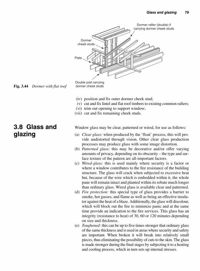
(iv) position and fix outer dormer cheek stud;
(v) cut and fix lintel and flat roof timbers to existing common rafters;
(vi) trim out opening to support window;
(vii) cut and fix remaining cheek studs.
Window glass may be clear, patterned or wired, for use as follows:
(a) Clear glass: when produced by the ‘float’ process, this will pro-
vide undistorted through vision. Other clear glass production
processes may produce glass with some image distortion.
(b) Patterned glass: this may be decorative and/or offer varying
amounts of privacy, depending on its obscurity – the type and sur-
face texture of the pattern are all-important factors.
(c) Wired-glass: this is used mainly where security is a factor or
where a window contributes to the fire resistance of the building
structure. The glass will crack when subjected to excessive heat
but, because of the wire which is embedded within it, the whole
pane will remain intact and planted within its rebate much longer
than ordinary glass. Wired glass is available clear and patterned.
(d) Fire protection: this special type of glass provides a barrier to
smoke, hot gasses, and flame as well as being an effective insula-
tor against the heat of a blaze. Additionally, the glass will discolour,
which will block out the fire to minimize panic and at the same
time provide an indication to the fire services. This glass has an
integrity (resistance to heat) of 30, 60 or 120 minutes depending
on size and thickness.
(e) Toughened: this can be up to five times stronger that ordinary glass
of the same thickness and is used in areas where security and safety
are important. When broken it will break into relatively small
pieces, thus eliminating the possibility of cuts to the skin. The glass
is made stronger during the final stages by subjecting it to a heating
and cooling process, which in turn sets up internal stresses.
Glass and glazing 79
Dormer rafter (double) ifcarrying dormer cheek studs
Dormercheek studs
Plate
Double joist carryingdormer cheek studsFig. 3.44 Dormer with flat roof
3.8 Glass andglazing

(f) Laminated: this is manufactured with two or more layers of
polyvinylbutyral (PVB) between the panes of glass to provide a
reduction in noise and ensures that the glass, if broken, remains
in place.
The thickness of glass used will depend on the surface area of the
window pane and its exposure to wind.
In certain circumstances, where persons could be put at risk if acci-
dental breakage occur (see BS 6262–4: 1994), glass sizes are restricted,
for example low-level glazing, including doors and side window panels.
Where such areas are to be glazed, special safety glasses are a neces-
sary requirement (see Chapter 4, section 4.6.6, Critical glazed areas).
When designing the sash, where possible, particular attention should
be made to the size of the glass panels in relation to the size of the sash
(this may also include doors with glass panels, see Fig. 4.21).
Figure 3.45 shows, geometrically, a method to obtain the size of the
glass pane. This is not only ‘pleasing’ to the eye, but is also in pro-
portion to the window sash – known also as the ‘Golden-ratio’:
(i) set compass to line a–b (the width of the panel) and scribe an
arc to give position c;
(ii) the compass is now set to b–c and an arc is scribed to give
position d (the height of the panel).
80 Windows
3.8.1 Size of glass
d
c
ab
Fig. 3.45 Obtaining the correct
proportion for glass panels
3.8.2 Fixing glass
Traditionally putty is used for securing glass. It is a mixture of Linseed
oil and inorganic fillers (BS 544: 1969) and applied using a putty knife
onto primed timber. The putty becomes semi-rigid after time, by
absorption into the timber and by oxidation – forming a skin.
The rebate size will depend on the thickness of the glass or double-
glazed unit and on the type of glazing material, for example putty or
glazing beads or glazing compounds.

Rebates designed for Linseed oil putty fronting (pointing) should be
at least 8 mm deep, unless they are for small frames. Non-setting com-
pounds and tapes will need a rebate 10 mm to 12 mm deep. Rebates
should be wide enough to receive 2 to 3 mm of back putty or com-
pound, the thickness of the glass or unit, and the putty fronting or
bead. It is important that rebates should be primed or sealed accord-
ing to the type of putty or compound used.
Figure 3.46 shows a typical arrangement for a single-glazed window
with putty-bed and fronting (pointing).
The window may be glazed in the following manner:
(i) Check that the glass is the right size for the opening, with 2 mm
clearance all round (Fig. 3.46a).
(ii) Run a putty bed around the back of the rebate (Fig. 3.46b).
(iii) Position setting blocks (short pieces of sealed hardwood or PVC)
in the bottom rebate (Figs 3.46c and 3.47). Location blocks (simi-
lar to setting blocks) may be required at the top and sides to pre-
vent glass movement within a casement when it is opened. (See
BS 8000: part 7: 1990, Workmanship on site. Code of practice
for glazing.)
(iv) Position the glass in the frame and gently and evenly press
around the edges until back putty squeezes out to leave at least
a 2 mm backing (Fig. 3.46d).
(v) Hold the glass in position with glazier’s sprigs (flat-cut nails)
positioned at about 400 mm centres (Fig. 3.46e). Sprigs are
tapped into place by sliding the head of a small hammer over
the glass.
(vi) Cut back the back putty at an angle to produce a sight-line for
the putty fronting (Fig. 3.46f).
Glass and glazing 81
(a)
(e) (f) (g)
(b) (c) (d)
Fig. 3.46 Single-glazed window
with putty fronting (pointing)
Note: Linseed oil putty is not suit-able when used with modernmicro-porous paints and stains.(See BS 8000: part 7: 1990,Workmanship on site. Code ofpractice for glazing.)

(vii) Run putty all the way round between the glass and the rebate.
Then, starting at the top, cut the putty back to just under the back
sight-line viewed through the glass, using a putty knife, a hacking
knife (preferable), or an old chisel; then work down the sides
and finally along the bottom in the same way (Fig. 3.46g). If
the putty pulls away from the glass this can be remedied by
gently running a thumb across or down the putty bevel.
Figures 3.47 and 3.48 shows the use of a front bead in place of putty
fronting. Glass may be beaded externally, as shown, or internally in
the case of extreme weather exposure and to provide greater security.
Beads may be nailed or screwed depending on the situation, with rust-
proof screws sunk into screw cups to facilitate removal. Screws should
be not more than 76 mm from the corners or 250 mm apart. Those parts
of the bead which are to make contact with the bedding medium should
be primed or suitably sealed to prevent absorption, as with rebates.
When non-setting compounds are used as a bedding, distance pieces
of a non-absorbent resilient material, e.g. plasticized PVC, are set
82 Windows
Note: As soon as the putty hasdried sufficiently it should bepainted over, masking the gap leftbelow the back sight-line. This willensure a weather-seal between theglass, the putty fronting, and theframework.
Glazing bead(screwed or nailed)
flush or with overhang
Glass
Glazing compound
Setting block
Sill
Fig. 3.48 Single-glazed window
with front bead
Min. 30 mmfrom corner of glass
Setting blocks(25 to 75 mm long)
Locationblocks
(25 mm long)
Fig. 3.47 Single-glazed window
with front bead

between the rebate and the back of the glass to prevent the compound
from becoming further compacted when the glass is subjected to
high winds. They are usually spaced at under 300 mm centres.
There are three main reasons why windows are double or secondary
glazed:
(i) To cut down the heat loss through single-glazed windows.
Thermal insulation values increase as the air space between panes
widens up to 20mm – this optimum value may then be maintained
until the gap reaches 200mm.
(ii) To reduce the incidence of condensation on the glass by allowing
the area within the inside surface of the glass to stay at a temper-
ature above the dew point (the temperature at which the water
vapour in the air condenses).
(iii) Double glazing can be designed to give good levels of noise
(unwanted sound) reduction by:
(a) providing good all-round airtight seals;
(b) increasing the glass thickness;
(c) providing an air space of between 100mm and 200mm
between panes; using sound-absorbing material as a lining
around the air space (secondary glazing – see Fig. 3.53);
(d) ensuring a different thickness of glass for the outer and inner
panes;
(e) insulating the window from its surrounding wall structure
with resilient material.
There are four different methods of providing double glazing:
(a) Sealed double-glazed units (Fig. 3.49): two panes of glass are
held apart by a spacer, then filled with dry air or an inert gas and
sealed. However, on more modern high-performance windows
Glass and glazing 83
3.8.3 Double andsecondary glazing
Non-setting compound
Bead Distance piece
Putty fronting
Optionalbead
Sprig
Sealed surface
Stepped-edged
Setting block
Square-edged (beaded)
Space 6 to 20 mm
Fig. 3.49 Fixing sealed double-
glazed units

(Fig. 3.16) the glass unit is usually 24mm thick to include two
4mm pieces of glass with a 16 mm gap.
Two types are available: ‘square-edged’ for wide rebates, and
‘stepped-edged’ for narrow rebates. The wider the space between
the panes, the better the thermal insulation; but sound insulation
values will, in the main, only be due to the double thickness of
glass (increased mass).
(b) Coupled windows (linked windows) (Fig. 3.50): these consist of
two casements hinged together, one of them also being hinged to
the window frame. Normally, both open while linked together, but
hinged separation is possible – usually for cleaning purposes.
(c) Secondary casements (sashes) (Fig. 3.51): these provide an add-
on method of double glazing. A glazed framework of timber,
metal, or plastics is attached to the inside of the existing window
framework. These secondary casements may be hinged, made to
slide, or static, but all should be detachable for cleaning purposes.
There are many proprietary systems on the market including the
use of aluminium extruded channels. These are secured to the win-
dow reveal and support vertical or horizontal sliding glass units.
Figure 3.52 gives an example of a proprietary horizontal sliding
secondary glazing used in a window reveal.
84 Windows
Coupling (linking)mechanism
Opening coupled
Divided
Weather-seal
SillFig. 3.50 Coupled (linked) win-
dows double glazing
Seal
Casement Hinged and/ordetachable inner
frame
Casement – fixedor opening
Fig. 3.51 Secondary casements
(sashes) double glazing

(d) Double windows (Fig. 3.53): these consists of two window
frames in the same opening – set apart with a gap of between
100mm and 200mm to give maximum sound insulation as pre-
viously described.
These can be made from solid timber, plywood, blockboard or MDF
(medium density fibreboard). Their back edge is tongued into a pre-
formed groove in the sill (Figs. 3.48 and 3.54a), while the board’s width
possibly (depending on the method of wall construction) spans a cavity.
Window boards 85
Plaster reveal
Horizontal view about A
Min 12 mm
Handle
Packer
Horizontal slidingsecondary glazed unit
(A)
Fig. 3.52 ‘Selectaglaze’
secondary glazing system
Outward opening
Inward opening orprovision for sliding
Insulation board
Stuck or planted bead(provides edge protection)
Sill
100 to 200 mm
Fig. 3.53 Double windows
3.9 Windowboards (Fig. 3.54)

The board is nailed or screwed down to the inner wall leaf via a series
of packings and plugs. Packings are positioned at intervals to suit the
board’s thickness. The thickness of the packing can be determined by
using a short end of window board, a wedge, and a short level as shown
in Fig. 3.54b.
86 Windows
A A
Inside elevation
Packings
Section A-A Level
(d)
(b)
Detail ‘b’(nosing returned)
Short end ofwindow board
PackingTemporary wedge to determine
packing thickness
Solid
Blockboard – solid nosing(tongued)
Plywood – solid nosing(rebated)
Veneered plywood – solid nosing(grooved)
(a)
Possible window – board profiles
Fixing via solidpackings
(c)
Fixing via thin folding wedges(procide easy adjustment)
Plastic foam filling
Plastic extrusion
MDF-Bullnosed
Fig. 3.54 Window boards and
their fixing

If the required thickness is non-standard, then folding wedges may be
used – slide one upon the other until the correct thickness is obtained,
then pin them together or nail them directly into the blockwork below
(Fig. 3.54c).
Because window boards are generally fixed before plastering is car-
ried out (first fix), there is no need for them to be a tight fit. It is usual
to let the front edge overhang the plasterwork and extend by that
amount beyond both reveals in which case, whatever front-edge finish
or shape is used, it should be repeated and returned around each end
as shown in Fig. 3.54d.
To seal the gap between the frame and brickwork, it is necessary to
provide some form of flexible sealant that will prevent the entrance
of moisture into the building. The sealant also needs to be flexible
enough to accommodate the movement of the building, as well as
provide a continuous seal against the elements and match to its appli-
cation (BS 6213: 2000).
Various sealants are available. These may be silicon or acrylic based
and are available in cartridges and applied around the frame by the use
of an applicator gun. The plastic nozzle may be cut to suit the diam-
eter of the bead required. After application, the bead of sealant can be
smoothed off by a damp rag, as well as any surplus before setting.
Expanded polyurethane foam is another type of sealant, which is
applied between window or door frames and their surrounding open-
ings after fixing, filling irregular gaps and improving insulation.
Windows should reach the site in a dry and semi-weather-protected
condition having been previously treated with a good-quality prim-
ing paint and/or a water-repellent type of preservative at their place
of manufacture.
Site storage should be such that windows are stacked flat or reared on
edge – and not as shown in Fig. 3.55.
Figure 3.56 shows two examples of proper storage:
● flat on bearers with spacers to allow for ventilation;● stacked vertically on edge (head to sill) on bearers with support to
prevent falling over.
Protection on site 87
3.10 Sealants
3.11 Protectionon site
3.11.1 Storage

In either case windows must always be positioned out of twist, and
preferably indoors. If they are to be stored in the open, stacks must be
kept off the ground, free from rising damp. The top and sides of stacks
should be protected from bad weather by a vented cover – air circu-
lation within the stack is essential to counter any condensation which
might otherwise form on the underside of the covering, particularly if
plastic sheeting is being used. The stack should be assembled and
covered in such a way that as windows are used from the stack, those
that remain are left with adequate vented cover.
Before frames are installed, those parts (particularly end grain) that are
to be enclosed within the wall structure, i.e. jambs, head, and sill
should be fully protected by painting against any ingress of moisture,
88 Windows
Fig. 3.55 How not to store win-
dow frames on site
Prop
WeightFloor bearer
Flat on bearers
Middle bearer to provideall-round air circulation
May also be stacked flat-head to sill on floor bearers
Vertical with support prop
Floor bearers
Fig. 3.56 Examples of proper storage of window frames
3.11.2 Preventativemeasures before andafter installation

etc. If, for whatever reason, the remaining exposed woodwork cannot be
fully protected against bad weather after installation, the whole frame-
work should be clad with polythene or similar impervious material.
Where window openings are used as access points for lengths of timber,
for example floorboard or skirting board, the exposed parts of the frame-
work which may make contact (i.e. sills and the lower parts of jambs
and mullions) should be temporarily boxed as shown in Fig. 3.57.
Hardware has been divided into three sections:
● Traditional cased windows● Modern and high performance windows● Double-hung sash windows
(a) Butt hinge: used on traditional type sashes (Fig. 3.6) with each
of the leaves of the hinge housed into the jamb and sash hanging
stile. Positioning of the hinges should be just below the top rail
and above the bottom rails so that end grain is avoided when let-
ting in the hinges.
(b) Stormproof hinge: for use on stormproof sashes (Fig. 3.6). These
are housed into the rebate of the sash hanging stile and into the
jamb. Positioning is similar to that for the butt hinge.
Window hardware (ironmongery) 89
Reveal lining –jamb (plywood)
A
B
Inner facing
Reveal lining – sill (plywood)
Outer facing
Horizontal section through B Vertical section through A
Plastics-foamself-adhesive strip
300 p
lus
Fig. 3.57 Sill and jamb protec-
tion against scuffing
3.12 Windowhardware(ironmongery)
3.12.1 Traditional (see Fig. 3.58)

(c) Easyclean hinge: this type of hinge is surfaced fixed and not
housed into the sash or jamb. Mainly used for windows above
ground level, due to the fact that possible intruders could remove
the hinges from outside. However, the advantages are that the hinge
requires no housing-in, and when opened allows the sash to swing
out enabling the outside of the glass to be cleaned.
(d) Casement stay: face fixed onto the bottom rail with two pins
secured to the top edge of the sill, it allows the sash to be opened
and secured in a number of set positions. When closing the sash,
the casement stay is positioned behind the inner off-set pin and then
hooked over the outer pin. By doing so, this will pull the sash tight
into the rebate.
(e) Window fastener: secured to the face of the sash closing stile, with
the ‘striking plate’ housed or surfaced fixed to the window jamb.
Once the window is closed the handle locks into the wedge shape
knuckle, thus locking and pulling the sash tight into the frame.
90 Windows
Knuckle
(a) Butt hinge (b) Stormproof hinge (c) Easyclean hinge
Closing edge
(d) Casement stay
Offset pin
StayPlan
Hinge
Pin
(e) Window fastener (wedge pattern)
Fig. 3.58 Casement window
hardware (ironmongery)

Modern window hardware may have a dual function, for example a
‘friction stay’ shown in Fig. 3.59 that serves as both a hinge and a
stay. Figure 3.59a shows the friction stay, in this case fitted to the
base of the sash for concealment. When fully open the outside of the
glass can easily be cleaned – ideal for windows above ground level.
The stay may also be fitted to the side of the sash (Fig. 3.59b) as top
hung, again concealing the hinge and allowing for easy cleaning of
the glass.
The ‘Titon Axaflex’ window stay (Fig. 3.60), however, doubles as a
fastener. It holds the sash open at various positions and when closed
locks it in place.
A variation on the two-pin casement stay (Fig. 3.58d) is the screw-
down adjustable stay (Fig. 3.61), which allows the sash to be locked
open at any position.
The window fastener shown in Fig. 3.62 includes a locking key for
security and has two latching positions: one with the casement fully
closed and the other with it partly open (13 mm gap at the closing
edge) – useful as a night vent.
When the fastener shown in Fig. 3.63 is closed it activates two lock-
ing mechanisms: one from behind the handle and the other from the
espagnolette bolt (rectangular steel bar), which is shot into the win-
dow head for greater security.
Window hardware (ironmongery) 91
(a) Side opening mechanism with friction stay
(b) Fully reversible pivoting mechanismFig. 3.59 Friction window stay
3.12.2 Modern andhigh performance
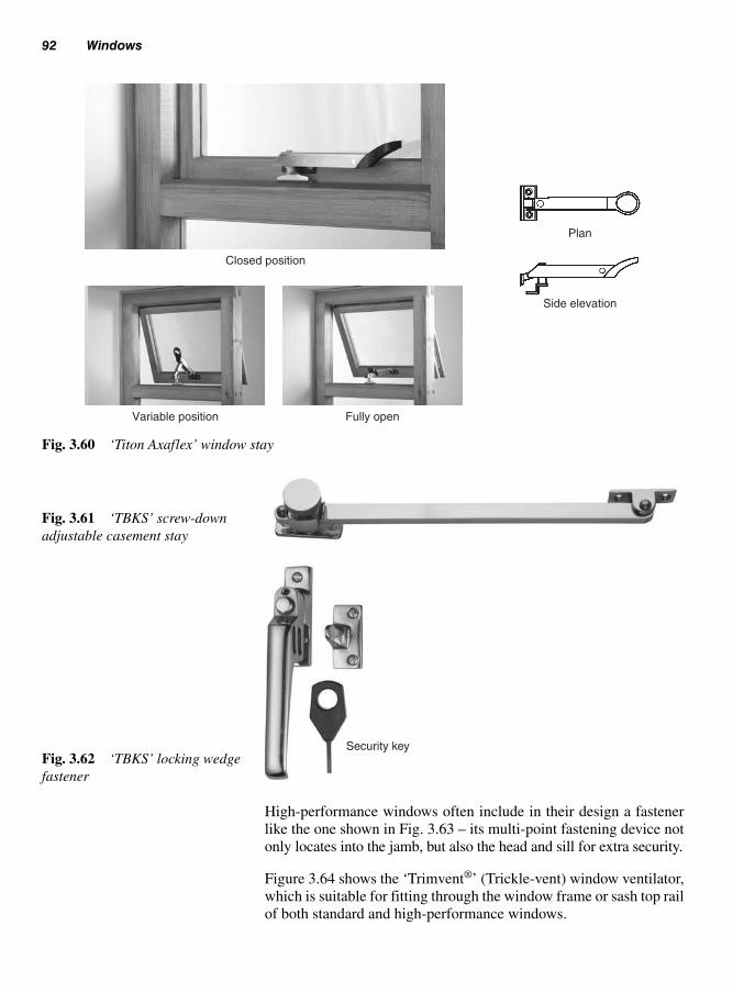
High-performance windows often include in their design a fastener
like the one shown in Fig. 3.63 – its multi-point fastening device not
only locates into the jamb, but also the head and sill for extra security.
Figure 3.64 shows the ‘Trimvent®’ (Trickle-vent) window ventilator,
which is suitable for fitting through the window frame or sash top rail
of both standard and high-performance windows.
92 Windows
Fig. 3.61 ‘TBKS’ screw-down
adjustable casement stay
Fig. 3.62 ‘TBKS’ locking wedge
fastener
Security key
Closed position
Plan
Side elevation
Variable position Fully open
Fig. 3.60 ‘Titon Axaflex’ window stay

Window hardware (ironmongery) 93
Espagnolette fitted to closing edge of sash Centre locking pointFig. 3.63 Multi-point fastener
Trickle-vent in head of frame
Trickle-vent in top rail of sash
Fig. 3.64 ‘Titon’ Trimvent®
window ventilator

Hardware used on double-hung sash windows includes:
● Weights (Fig. 3.17); (see section 3.2.12);● Chains/cords (Fig. 3.23); (see section 3.2.13);● Spiral spring balances (Fig. 3.24); (see section 3.2.14);● Sash pulleys (Fig. 3.65) – usually housed into the top of the pul-
ley stiles (two each side) with the wheel made of either pressed
Cast-iron, brass or nylon to accommodate the cord or chain;● Sash fastener (Fig. 3.66) – shows three types available, each is
secured to the sash meeting stiles and may be secured by a turn-
screw or key;
94 Windows
Fig. 3.65 Sash pulley
Lever fastener (locking) Brighton sash fastener Fitch fastener (locking)
Fig. 3.66 Sash fasteners
Fig. 3.67 Sash lift
3.12.3 Double hungsash windows

Window hardware (ironmongery) 95
References
BS 6262–4:1994, Glazing for buildings. Safety related to human
impact.
BS 644: 2003, Timber windows.
BS 7413: 2002, Unplasticized polyvinyl chloride (PVC-U) profiles for
windows and doors. Specification.
BS 6213: 2000, Selection of construction sealants. Guide.
BS 8000: 1990 part 7, Workmanship on site. Code of practice for glaz-
ing.
BFRC Window energy rating (WER) is now available rated between A
and G on a BFRC window energy label, similar to home appliances
(‘A’ being the most efficient).
CP 153: part 2: 1970 (Table 3).
Building Regulations Approved Document F: 2000.
Building Regulations Approved Document L1 and L2, Conservation
of Fuel and Power: 2002.
Building Regulations Approved Document N, Glazing – safety in rela-
tion to impact, opening and cleaning: 2002.
● Sash lift (Fig. 3.67) – secured to the bottom rail it enables the
bottom sash to be lifted to the required position.

Doors, door frames and linings are an integral part of a domestic build-
ing and must provide a method of easy access or egress for any part of
the dwelling without restrictions. This also applies to any outbuildings,
which will require the same conditions.
There are many different door designs that may be straightforward
and plain, or ones that include panels, glazed areas and even circular
headed. However, whichever door is selected it must suit the dwelling
and be aesthetic in design.
This chapter deals with a variety of doors and the methods used to
support them, including the various types of ironmongery required
for them to work efficiently.
Doors may be divided into four main groups and may be used intern-
ally or externally according to their appearance and method of con-
struction:
(i) Unframed (matchboard) doors (Fig. 4.1):
(a) ledged and battened;
(b) ledged, braced, and battened.
(ii) Framed doors (Fig. 4.1):
(a) framed, ledged, and battened;
(b) framed, ledged, braced, and battened;
(c) panelled (solid and/or glazed).
(iii) Flush doors (Fig. 4.1):
(a) plain;
(b) panelled (vision panels).
(iv) Special doors (Fig. 4.1):
(a) shaped heads;
(b) double margin;
(c) stable door.
Domestic doors,frames and linings
4
4.1 Classification(single-leaf doorpatterns)

Classification (single-leaf door patterns) 97
Doors may be further subdivided by their siting and/or function. For
example, exterior doors must be designed to exclude the weather from
the building and be strong enough to provide security – they are there-
fore generally thicker, heavier, and more substantial in construction than
Unframed
Matchboarded
Framed
Single panel
GBS/D
GBS/D
GBS/D
GBS/D
Framed
Two-panel Three-panelSingle panel
Framed
Four-panel Six-panel Eight-
panel
Flush
Plain
Optional glazed areas
Glazed areas
Special doorsFlush
Vision panel Panelled effect (embossed)
Note: GBS/D–glazing bar sub-division.Fig. 4.1 Examples of
single-leaf door patterns

98 Domestic doors, frames and linings
interior doors. Fire doors (section 4.10) provide fire resistance between
compartments, etc. Louvred doors provide permanent ventilation.
Domestic doors are available in many sizes, which are indicated in
Tables 4.1 to 4.3 – most are indicated in both imperial and metric sizes.
4.1.1 Door types
Table 4.1 Exterior door sizes
Height Width Thickness
Exterior metric single-leaf doors2000 mm 807 mm 44 mm2040 mm 726 mm 44 mm2040 mm 826 mm 44 mm
Exterior metric double-leaf doors2000 mm 1106 mm 44 mm
Exterior imperial single-leaf doors6�6� (1981) 2�0� (610) 13�4� (44)6�6� (1981) 2�3� (686) 13�4� (44)6�6� (1981) 2�6� (762) 13�4� (44)6�6� (1981) 2�9� (838) 13�4� (44)6�8� (2032) 2�8� (813) 13�4� (44)
Exterior imperial double-leaf doors6�6� (1981) 3�10� (1168) 13�4� (44)
Table 4.2 Internal door sizes
Height Width Thickness
Interior metric single-leaf doors2040 mm 626 mm 40 mm*2040 mm 726 mm 40 mm*2040 mm 826 mm 40 mm*Interior imperial single-leaf doors6�6� (1981) 2�0� (610) 13�8� (35)6�6� (1981) 2�3� (686) 13�8� (35)6�6� (1981) 2�6� (762) 13�8� (35)6�6� (1981) 2�9� (838) 13�8� (35)Interior imperial double-leaf doors6�6� (1981) 3�10� (1168) 13�8� (35)6�6� (1981) 4�6� (1372) 13�8� (35)
*Fire doors are 44 mm thick
Table 4.3 Mobility door sizes
Height Width Thickness
Mobility single-leaf doors2040 926 40*
*Fire doors are 44 mm thick

Ledged-braced and battened door 99
840 mmmax.
Ledge:20 × 91 min.
2055 m
m m
ax.
H H
H H
Front elevation
E � EqualH � Hinge
E E
Battens(matchboard15 mm min.
Ledge:20 × 91 min.
150 � 5 mm38 mm
150 � 5 mm
15 � 5 mm
Rear elevation
Plan
(b)
Alternative detailing
Batten(matchboard)
Brace
Ledge
(d)(c) Arrow-headed bracing(chevron bracing)
(a)
(i) (ii) (iii) (iv)
Variations on matchboard joints
(i) ‘V’ tongue-and-groove (vt&g) (ii) ‘V’ both sides (vt&g)
(iii) Bead one side (t&g) (iv) Bead both sides (t&g)
Note: Sizes shown are finished sizes
Fig. 4.2 Ledged-braced and battened (matchboarded) door construction
These types of doors (door leafs) are commonly used as exterior doors
to outhouses, sheds, garages (for pedestrian access), and screens.
Provided they are made and fixed correctly, they will withstand a lot
of harsh treatment and remain serviceable for many years.
As can be seen from Fig. 4.2, the face of the door is made up of V or
beaded tongue-and-groove matchboard, known as ‘battens’ (Fig. 4.2a).
4.2 Ledged-braced andbattened door(Fig. 4.2)
4.2.1 Construction

100 Domestic doors, frames and linings
These are nailed or stapled to three horizontal members called ‘ledges’.
These ledges (if the door opens outwards the top edges should be
bevelled, see Fig. 4.2b) are held square to the battens by similarly fix-
ing two diagonal pieces of timber called ‘braces’ (Fig. 4.2d).
A less expensive version of this door is the ledged-and-battened
door. As its name implies, it is built without a brace – its suitability
therefore relies entirely upon its nailed construction, which under
normal circumstances would prove inadequate. It can however, be
used quite satisfactory in small openings or as a temporary door.
The importance of a brace is illustrated in Fig. 4.3, where it will be
seen that its effectiveness is controlled by its direction. If the door is
to retain its shape, the brace must always point away and in an upwards
direction from the hanging side (hinged side), otherwise the door could
sag at the closing side (see Fig. 4.4) – hence the term ‘sag bar’ some-
times used when referring to a brace.
This means that this type of door should be handed (designed to hang
either its left or right hand side). To avoid this, manufacturers either
supply the braces loose to be fixed in situ (on site) to suit the hand-
ing, or fix them as a chevron pattern (Fig. 4.2c) – in this way only one
of the braces is fully effective. To further increase the effectiveness
of the brace, particularly in more heavier doors, the ends of the braces
can be cut into the ledges using a bird’s mouth joint (Fig. 4.2d).
Figure 4.4 shows how a ledged-and-battened (matchboard) door should
not be fixed.
The making of a simple card or wood model (Fig. 4.5) should help
clarify bracing principles:
1. Cut four pieces of stiff card, thin plywood, or hardboard, etc.,
500 mm long by 50 mm wide to form the sides, top and bottom.
2. Join them together at the corners with a single nail, pin, or screw.
This will allow each corner to pivot and produce a scissor movement.
3. Lay the frame flat. Move the corners until they are square (at
90° to each other).
4. Cut a piece of rigid material to fit between corners A and C – this
will act as the brace.
5. While the brace is held in position take hold of side H. Lift the
whole frame up and turn it until vertical. The brace should now
be self-supporting, and therefore the frame will remain square.
However, if the bracing piece has been omitted, or positioned into
the opposite corners B and D, the frame would have collapsed. In
4.2.2 Door braces

Ledged-braced and battened door 101
Dead weight of door
Hinge(H)
Hinge(H)
Unbraced Braced inwrong direction
Fullybraced
Arrowheadchevron bracing
StableUnstable
Bra
ce in
com
pres
sion
(sa
tisfa
ctor
y)
Hanging sideWeight of doorrestrained by
hinges
Closing sideUnrestrained-
requires brace toprevent door from
sagging
Indicates possible movement when braceis omitted or positioned in wrong direction
Brace in tension (unsatisfactory)
H
H
H
H
H
H
H
H
Fig. 4.3 Bracing principle
fact, corners B and D would have become wider apart (Figs 4.5a
and b), so allowing the brace to fall out.
Figure 4.6 shows some of the requirements specified by BS 459:
1988 for the construction of a ledged-and-braced battened door, but
it is worth noting that traditionally such doors have been and are still
in some cases made from heavier sectioned timber. They may also
include other features such as those shown in Fig. 4.2, for example
weathering to ledges (bevelling on their top edge) where the door is
4.2.3 Assembly

102 Domestic doors, frames and linings
subjected to weather from both sides (Fig. 4.2b), or extra brace
restraint by housing braces into the ledges (Fig. 4.2d).
A typical order of assembly for a ledged-and-braced battened door is
illustrated in Fig. 4.6.
Stage 1
(a) Cut the battens and ledges to length;
(b) Check that the ledges are not twisted (plane them out of twist if
necessary);
(c) Paint or preserve all the tongues and grooves and the ledge faces
that will come into contact with the battens;
(d) Rest the battens face down across the bearers, then lightly cramp
the battens together;
(e) Double-screw each ledge to the cramped edge battens (Fig. 4.7).
Stage 2
(a) Cut the braces to fit between the ledges;
(b) Edge-nail the braces to the ledges (ensure that the door is kept
square during this operation – if necessary use end stops).
Fig. 4.4 Example of door sag (missing
‘sag bar’)
Brace (sag bar) removed
H
a
D C
A B
b
H
H
Hangin
g s
ide
Pin
Fig. 4.5 Model to simulate frame movement
Note: Widening gap at the top ofthe door (due to omission orwrongly positioned brace). Alsothe ‘thumb latch’ closing mecha-nism (see section 4.18, Hardware)should not have been used in thissituation – the ‘beam’ is on thewrong side of the door face (seeFig. 4.77)

Ledged-braced and battened door 103
E E
E
E
E
Note: Wider door
E
Fig. 4.7 Positioning edge
battens
Stage 1
Stage 2
Stage 3 Stage 4
Fig. 4.6 Stages of assembly
Note: Edge battens must be equal(E) and of sufficient width to allowfor fixing. This is achieved by placing either a batten or joint tothe centre of each ledge.

104
Do
me
stic
do
ors
, fram
es a
nd
linin
gs
Table 4.4 Sequence of operations for ledged braced and battened door construction
Powered Process Item Member Operations Machines hand tools Hand tools Ironmongery Remarks
Preparing Door Ledges, Cut to Cross-cut – – – Cut to nominal size timber battens, length, circular saw (Ex)
braces ripping, benchdeeping
Planing Hand-feed Planer Hand plane – Finished size – width planer/surfacer, and thicknesspanel thicknesser
Battens Form V, Spindle Router Rebate plane – Worked by machine tongue-and- moulder Plough plane or handgroove
Assembly Door Battens, Fix battens Nail gun, Hammer Nails/staples Paint or preserve ledges, to ledges power driver T & Gs – leave to braces dry before assembly
Cut bevel – Chop saw Panel saw, –and fix hammer
Punch and – – Hammer, – Boards held face to clench nails nail punch face during treatment
Finish Door * Sanding Belt sander Belt, Orbital Cork sanding – Finish depends on or random block, glass or grade of abrasive
garnet paper usually before assembly
Door Knotting – – Paint brush – Shellac knotting Painting primer paint
* This depends on the type of finish. For varnishing/polish finish a belt sander would be used, with the grain. For a paint finish an orbital/random sander is used to prepare the surface and help with the adhesion of the paint to the wood

Framed-ledged-braced and battened doors 105
Stage 3
(a) Turn the door over on to bearers which have been placed length-
wise;
(b) Double-nail each batten to the ledges and braces taking care to
avoid the bearers as after the nails have been punched below the
surface they will protrude 10 mm through the door.
Stage 4
(a) Turn the door back onto its face, where the protruding point of
each nail will be visible;
(b) Clench each nail by bending it over in the direction of the grain,
then punch the clench below the surface of the wood.
An overall sequence of operations can be listed in chart form as an
easy means of reference. Table 4.4 shows how the door’s construc-
tion can be tabulated.
The only difference between this type of exterior door and the ledged-
braced-and-battened door is the addition of a frame around the
matchboarding.
This door is constructed of all solid softwood and is designed to
withstand a reasonable amount of rough treatment. It is quite often
used in and around farm and industrial buildings.
The frame, as shown in Fig. 4.8, has two stiles and a top rail, which
are of the same thickness. The bottom rail and the middle (lock) rail
are thinner, to allow for the batten thickness plus 2 mm. All joints are
either: through mortised-and-tensioned (the bottom and middle rails
having bare-faced tenons) with proportions as illustrated; glued,
wedged, and pinned with hard wood or metal (star) dowels; or dowel-
jointed as described for panelled doors (section 4.5).
Braces should be a close fit between the stiles and the rails, be butted
or tongued, and be positioned to slope upwards and away from the
hanging side of the door (see Fig. 4.2).
Battens (matchboard) should be tongued-and-grooved with V or
bead joints and tongued or rebated into the stiles and top rail,
then nailed or stapled (with a pneumatic nail gun) to all framing
members.
4.3 Framed-ledged-bracedand batteneddoors
4.3.1 Construction

106 Domestic doors, frames and linings
All tongues, grooves, and rebates should be painted or treated with
wood preservative before assembly. (See Volume 1, Chapter 3, taking
into account the safe use and storage of wood preservatives.)
This type of door was originally used on farm stable buildings when
housing horses or ponies, but has become more popular recently in
domestic buildings as a back door into the garden from the kitchen or
utility room (Fig. 4.9). It is divided into two halves, which allows the
top half to be open while the bottom half can be securely shut. When
4.4 Stable door
Brace 30 × 95Stile 45 × 95
36 mm Min.
T
T
T
W
T
T
Top rail
Alternativesabout A-A
Middle rail30 × 145
36 mm Min.
Bottom rail30 × 145
T � Not to exceed 5 × WW � Not less than 12 mm and not more than 16 mmSee also Volume 1, section 10.3.3
45 × 95 mm
Equal
Equal
A Part elevation
Matchboard inset 2 mm
Alternative sections through B
A-A
B
A
Min. 18Max. 32
W
W
Fig. 4.8 Framed-ledged-braced
and battened door
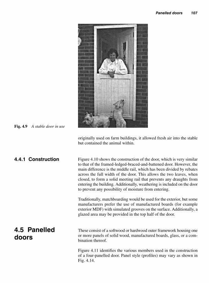
Panelled doors 107
originally used on farm buildings, it allowed fresh air into the stable
but contained the animal within.
Figure 4.10 shows the construction of the door, which is very similar
to that of the framed-ledged-braced-and-battened door. However, the
main difference is the middle rail, which has been divided by rebates
across the full width of the door. This allows the two leaves, when
closed, to form a solid meeting rail that prevents any draughts from
entering the building. Additionally, weathering is included on the door
to prevent any possibility of moisture from entering.
Traditionally, matchboarding would be used for the exterior, but some
manufacturers prefer the use of manufactured boards (for example
exterior MDF) with simulated grooves on the surface. Additionally, a
glazed area may be provided in the top half of the door.
These consist of a softwood or hardwood outer framework housing one
or more panels of solid wood, manufactured boards, glass, or a com-
bination thereof.
Figure 4.11 identifies the various members used in the construction
of a four-panelled door. Panel style (profiles) may vary as shown in
Fig. 4.14.
4.4.1 Construction
4.5 Panelleddoors
Fig. 4.9 A stable door in use

108 Domestic doors, frames and linings
The frame includes two stiles, with two or more rails (top rail, bot-
tom rail, middle or lock rail, glazing bars, and/or intermediate/frieze
rails) and in some cases intermediate vertical members (muntins
and/or glazing bars).
Joints between members may be mortised-and-tenoned or dowel-
jointed.
Glazing bars are mortised-and-tenoned (see Chapter 3, Figs 3.22c to f
for double-hung sashes).
4.5.1.1 Mortise-and-tenon joints (Fig. 4.13a)
The top, bottom, and at least one more rail (except with single-panel
doors) should be through-jointed. Stub tenons into stopped mortise
Possible provisionfor dead light
(glazed panel)
Split middle rail(rebated meeting rails,
opening inwards)
Verticalsection A-A
(meeting rails)
Front elevation
Mastic seal
Possible weatheringarrangement to bottom rail
B
A
A
Rebatedbottom rail
Alternative vertical sectionthrough B
Seal
Fig. 4.10 Stable door
construction
4.5.1 Construction

Panelled doors 109
holes can be used to join any other rails to stiles or muntins to rails –
fox wedging may be employed as shown in Fig. 4.12.
Tenon thickness should in nearly all cases be as near to one-third the
thickness of the members being joined as is practicable (depending
Fig. 4.11 Traditional four-
panelled door with alternative
panel arrangements
Hinge
A (V) B (V)
A/B (H)
D (H)
D (V)C (V)
C (H)
Top rail
Closing stile
(b) Panel(Bead flush)
Muntin
(d) Panel(Raised and
fielded)
Bottom rail
(a) Panel(Bead butt)
Middle or lockrail
Hanging stile
(c) Panel (Raised)
Hinge
Note: See also Fig. 4.14
(H) �
(V) � VerticalSection
HorizontalSection
Fig. 4.12 Fox-wedged stub
tenons
Saw kerf
Wedges
Unwedgesdovetailed mortise
Vertical section midway through joint
Wedles foxed

110 Domestic doors, frames and linings
on chisel size). The tenon width should not exceed five times its thick-
ness. Haunches should be as deep as the tenon is thick and never less
than 10 mm. Tenons should be clear of the top and bottom of the door
by a distance not less than 36 mm – see Fig. 4.8. All joints should be
glued and wedged as necessary.
Where moulding has been worked (stuck) on to the inside edge or
edges of the door framework, rail ends should be through-scribed as
shown in Fig. 4.13a.
4.5.1.2 Dowelled joints (Fig. 4.13b)
Dowels should be made of hardwood or of the same species as the
members being jointed – not less than 16 mm in diameter and
125 mm in length and at centres of not more than 55 mm, with no less
than the number of dowels per joint as shown in Table 4.5.
Dowels to bottom rails should be not less than 45 mm up from the
bottom of the door. All dowels must be fluted and joints glued. Joints
to moulded sections should be through-scribed, with tongues to help
stiffen the joints.
Note: Hand-made doors may bepart-scribes as shown in Chapter3, Fig. 3.22a
Fig. 4.13 Through-scribes
(a) (b)
(a) Single-Haunched mortise and tenon
(b) Double dowelled
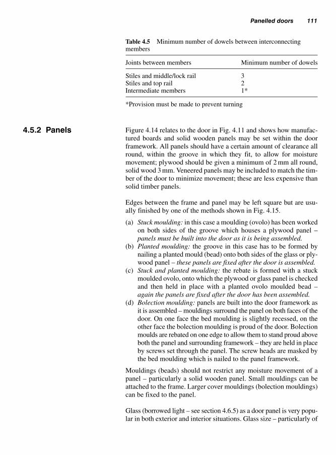
Panelled doors 111
Figure 4.14 relates to the door in Fig. 4.11 and shows how manufac-
tured boards and solid wooden panels may be set within the door
framework. All panels should have a certain amount of clearance all
round, within the groove in which they fit, to allow for moisture
movement; plywood should be given a minimum of 2 mm all round,
solid wood 3 mm. Veneered panels may be included to match the tim-
ber of the door to minimize movement; these are less expensive than
solid timber panels.
Edges between the frame and panel may be left square but are usu-
ally finished by one of the methods shown in Fig. 4.15.
(a) Stuck moulding: in this case a moulding (ovolo) has been worked
on both sides of the groove which houses a plywood panel –
panels must be built into the door as it is being assembled.
(b) Planted moulding: the groove in this case has to be formed by
nailing a planted mould (bead) onto both sides of the glass or ply-
wood panel – these panels are fixed after the door is assembled.
(c) Stuck and planted moulding: the rebate is formed with a stuck
moulded ovolo, onto which the plywood or glass panel is checked
and then held in place with a planted ovolo moulded bead –
again the panels are fixed after the door has been assembled.
(d) Bolection moulding: panels are built into the door framework as
it is assembled – mouldings surround the panel on both faces of the
door. On one face the bed moulding is slightly recessed, on the
other face the bolection moulding is proud of the door. Bolection
moulds are rebated on one edge to allow them to stand proud above
both the panel and surrounding framework – they are held in place
by screws set through the panel. The screw heads are masked by
the bed moulding which is nailed to the panel framework.
Mouldings (beads) should not restrict any moisture movement of a
panel – particularly a solid wooden panel. Small mouldings can be
attached to the frame. Larger cover mouldings (bolection mouldings)
can be fixed to the panel.
Glass (borrowed light – see section 4.6.5) as a door panel is very popu-
lar in both exterior and interior situations. Glass size – particularly of
Table 4.5 Minimum number of dowels between interconnectingmembers
Joints between members Minimum number of dowels
Stiles and middle/lock rail 3Stiles and top rail 2Intermediate members 1*
*Provision must be made to prevent turning
4.5.2 Panels

112 Domestic doors, frames and linings
Panel typePart vertical
section through railsPart horizontal
section through rails or muntin
Square-edgedplywood or
MDF
Bead and butt(Fig. 4.11a)
Bead flush(Fig. 4.11b)
Raised(Fig. 4.11c)
Raised andfielded
(Fig. 4.11d)
Raised, sunkand fielded(Fig. 4.30)
Sunk
Fielded (flat)
Raised
Plywood/MDF
Bead
Planted bead can be used atthe top and bottom of panels to
reduce end-grain exposureand short grain
Fig. 4.14 Vertical and horizon-
tal sections through different
panel types (see Fig. 4.11)
Manufactured board Manufactured board or glassManufactured board
or solid timber
(a) Stuck moulding (Ovolo) (c) Stuck and planted (d) Bolection moulding(b) Planted mould
Fig. 4.15 Detailing between frame edge and panel

Flush doors 113
an unbroken (i.e. without glazing bars) area within a door – is very
important because of the high risk of injury if breakage occurs. Rec-
ommendations for such situations can be found within BS 6262–4:
1994, Glazing for buildings. Safety related to human impact – see
also Chapter 3, section 3.8, Glass and glazing.
Figure 4.16 shows a type of panelled door made up using a timber
framework containing a cellular core that has been clad both sides
with either hardboard or plastics (PVCu).
Both faces of the door have been moulded to give the appearance of
a traditional panelled door, which can include an aperture for glazing.
Generally, moulded doors with plastics facings are used in external
situations, whereas internal doors are faced with hardboard that has
been pre-treated with a primed textured wood grain finish suitable to
receive a paint or wood stain.
Except for glazed and louvred apertures, the whole outer surface of a
flush door should be perfectly flat.
Both interior and exterior qualities of doors can be constructed – gen-
eral construction and the type of adhesive used in the manufacture of
the facing material being the main differences. Other factors include
door thickness, rigidity, and provision for fixing hardware, etc.
With the exception of the solid (laminated timber) door, some form
of framework will be required to retain the core of the door and/or
provide a fixing for rails, etc.
Top, bottom, and intermediate rails should be notched or bored (Fig.
4.18) to allow movement of air through the door to help prevent
4.5.3 Moulded paneldoors
4.6 Flush doors
4.6.1 Construction(Fig. 4.17)
‘X’ mesh (Fig. 4.17) core
Stile
35 or 40 mm, depending on
door type
3 mm moulded hardboard floor facings
Section A-A
Moulded hardboard facing in one piece over both faces
A ABuilt-up timber
lock block
Fig. 4.16 Panel effect moulded
door

114 Domestic doors, frames and linings
Laminated(solid core)
Laminatedsolid core
Vent slot(saw kerf)
Honeycombed core –paper/cardboard
Hollow boredcore
‘X’ mesh core
Vent hole(bored)
Particle boardcore
Timber rails Softwood spirals(shavings)
Framed solidcore
Hinge block(optional)
Lock block
Hollow(glazed aperture)
cellular(various cores)
Letter plate rail
Fig. 4.17 Framework for
flush doors – together with their
core
Vent hole
Vent slot (saw kerf)
Fig. 4.18 Venting top, inter-
mediate, and bottom rails

Flush doors 115
distortion (air becoming trapped within the core of the door) at the
assembly stage and so that, in the case of interior doors, air within
can be at equilibrium with that which surrounds it.
The framework is assembled in a very simple fashion. Joints may be
mortised-and-tenoned, but are more likely to be tongued-and-grooved
or butted and stapled together. With cellular doors, the main strength
of the door is derived from the stressed skin linings (facings), which
clad both sides of the frame and its core.
Solid cores include laminated timber and sheet particle board (chip-
board or flax board). Hollow cores include rails tenoned into mor-
tised stiles or tongued into grooved stiles. The cellular boxes are
formed using cross-halved timber or hardboard, paper/card strips, or
softwood spirals formed by shaving short blocks of wood of uniform
thickness.
Facings are generally plywood or hardboard, often with a decorative
face veneer. Exterior-door facings should be of weather-resistant
material, for example exterior-grade plywood or oil-tempered
hardboard. Facings are glued under pressure to the framework and
core.
4.6.2 Cores (Fig. 4.17)
Framed coreHardboard or MDF
3 or 5 ply
Decorative veneer
Fig. 4.19 Door facings
4.6.3 Facings (Fig. 4.19)
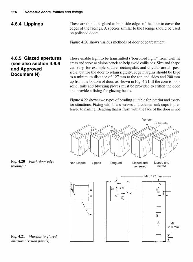
116 Domestic doors, frames and linings
These are thin laths glued to both side edges of the door to cover the
edges of the facings. A species similar to the facings should be used
on polished doors.
Figure 4.20 shows various methods of door edge treatment.
These enable light to be transmitted (‘borrowed light’) from well lit
areas and serve as vision panels to help avoid collisions. Size and shape
can vary, for example square, rectangular, and circular are all pos-
sible, but for the door to retain rigidity, edge margins should be kept
to a minimum distance of 127 mm at the top and sides and 200 mm
up from the bottom of door, as shown in Fig. 4.21. If the core is non-
solid, rails and blocking pieces must be provided to stiffen the door
and provide a fixing for glazing beads.
Figure 4.22 shows two types of beading suitable for interior and exter-
ior situations. Fixing with brass screws and countersunk cups is pre-
ferred to nailing. Beading that is flush with the face of the door is not
4.6.4 Lippings
4.6.5 Glazed apertures(see also section 4.6.6and ApprovedDocument N)
VeneerSubstrate
Lipped andmitred
Lipped andveneered
TonguedLippedNon-LippedFig. 4.20 Flush-door edge
treatment
Min. 127 mm
Min.200 mm
Fig. 4.21 Margins to glazed
apertures (vision panels)

Louvred doors 117
recommended, as this will cause the surface finish (paint or varnish)
to crack along the joint at the edge of the door due to the timber
movement of the beading.
Before exterior doors are beaded, the aperture edges should be sealed –
waterproof tapes can be used.
Glass as a material when used in doors can be very dangerous when
broken, especially at positions where there is a possibility that this
may occur – either accidentally or on purpose (vandalism). For this
reason glass must be strong enough to withstand human impact (see
Building Regulations Approved Document N: 2000, BS 6206: 1991,
and Chapter 3, section 3.8).
In Fig. 4.23 the areas indicated are ‘critical’ areas in terms of safety
and if broken must disintegrate into small particles that are not sharp
or pointed. This also applies to windows.
In most cases, the purpose of a louvre sited within a door is to accom-
modate the need for permanent ventilation through it. Figure 4.24
shows how this is achieved, while at the same time offering privacy
and, in the case of an exterior door (depending on blade pitch and pro-
jection), weather protection. Figure 4.25 shows how louvres may be
sited to suit different types of door.
Figure 4.26 shows details of how a lightweight interior louvred
wardrobe or airing cupboard door could be constructed.
4.6.6 ‘Critical’ glazedareas (doors andscreens) (Fig. 4.23)
10 Bolectionbead
6
Interior doors Exterior doorsFig. 4.22 Glazing beads
4.7 Louvreddoors
4.7.1 Construction
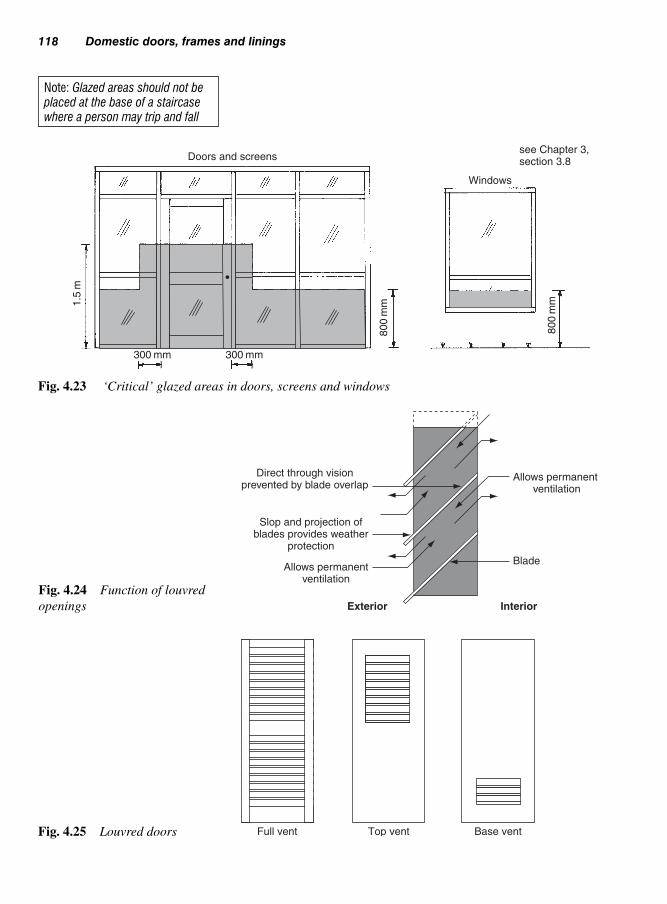
118 Domestic doors, frames and linings
Doors and screens
Windows
1.5
m
300 mm 300 mm
800
mm
800
mm
see Chapter 3,section 3.8
Fig. 4.23 ‘Critical’ glazed areas in doors, screens and windows
Direct through visionprevented by blade overlap
Slop and projection ofblades provides weather
protection
Allows permanentventilation
Allows permanent ventilation
Blade
Exterior Interior
Fig. 4.24 Function of louvred
openings
Full vent Top vent Base ventFig. 4.25 Louvred doors
Note: Glazed areas should not beplaced at the base of a staircasewhere a person may trip and fall

Louvred doors 119
Louvres in exterior doors usually have to provide security. They are
therefore more sturdy in construction – as shown in Fig. 4.27. If the
louvred area is such that when the louvres are removed this leaves an
aperture large enough for a person to pass through, then this becomes
a security risk. In this case, a secondary barrier in the form of a steel
grille (or similar) should be considered.
75
60°
45°
100
30
Vertical section
Fig. 4.26 Lightweight interior
louvred door
A Optional security grill
Overlap
45°
Section A-AA
Scollop
Fig. 4.27 Louvre suitable for an
exterior situation

120 Domestic doors, frames and linings
This type of door is used where an opening is too wide to accommo-
date a normal size door and not wide enough for two separate doors,
which would otherwise look out of proportion. For this reason a dou-
ble margin door is used to give the impression that there are two sep-
arate doors, but in fact there is only one door.
Generally, the door incorporates panels surrounded by a frame to
include stiles, meeting stiles, top rails, frieze rails, middle rails and
bottom rails. Wedged mortise-and-tenon joints are used throughout
as well as folding wedges (Fig. 4.29) and a loose tongue to secure the
meeting stiles (Fig. 4.30).
The door is assembled first by jointing together the meeting stiles using
glue and three sets of folding wedges, which need to be cut back below
the depth of the grove running around the internal edges of the frame.
This prevents the ends of the wedges protruding through into the groove
if any shrinkage takes place in the timber, which could in turn dam-
age the panels.
4.8 Doublemargin doors(Fig. 4.28)
Meeting stiles
Hanging stile
Frieze rail
Panel
Middle rail
A A
Fig. 4.28 Double margin door
4.8.1 Construction
Note: See Figs 4.29 and 4.30 fordetails

Double margin doors 121
Loosetongue
Meeting stile
Bead-butt-moulding
Folding wedges
Meeting rails
Folding wedges cutback below groove
Isometric detail aboutA-A, see Fig. 4.28
Key to jointing meeting stiles(see Fig. 4.28)
Fig. 4.29 Method of securing
meeting stiles with folding
wedges
Fig. 4.30 Use of loose tongue to
secure meeting stiles (see also
Fig. 4.14)

122 Domestic doors, frames and linings
Galvanized metal bar
Top rail
Meeting stile
Fig. 4.31 Galvanized metal bar
to strengthen door
Shaped top rail
Vertical glazing bar
Horizontal glazing bar(lay - bar)
Middle rail
Stile
Bottom rail
A A
Door stile Match boarding
Horizontal section A–A
Fig. 4.32 Doors with segmented
shaped head

Double margin doors 123
Next, the top rails, frieze rails, middle rails and bottom rails are inserted
into the meeting stiles followed by all the panels. Finally, the outer
stiles are secured and the whole door is cramped and checked for square
before all the outer wedges are inserted. Dowels are also inserted in
the joints for further strength.
After the door has been reduced in height, galvanized metals bars
25 � 6 mm are housed into the edges (which are stopped 12 mm from
each end) at the top and bottom of the door and secured with non-
corrosive screws (Fig. 4.31). This will help strengthern the two leafs
Matchboarding
Door stile
Fig. 4.33 Matchboarding simi-
lar thickness to door
Matchboarding
Alternativemethod
Door stileFig. 4.34 Matchboarding
both sides

124 Domestic doors, frames and linings
and prevent the door from sagging. One and a half pairs of 100 mm
hinges are used to hang the door.
Figure 4.32 shows an example of a door with a segmented top rail suit-
able for internal use, where both sides of the door have been faced with
tongue-and-groove boarding (matchboarding) below the middle rail.
Any joinery that involves circular work often requires the production
of a setting-out rod to produce the curved work full size to enable tem-
plates and jigs to be made for use with woodworking machinery.
For doors of similar design used externally, the matchboarding
would run past the bottom rail for weathering purposes similar for a
framed-ledged-and-braced door (Fig. 4.8) with the matchboarding on
the external face only. Volume 2, section 4.1 gives examples of the
methods used to set out various geometrical shapes.
Again, mortise-and-tenon joints are used for the rails into the stiles
with the matchboarding supported by a groove running around the
inside edges of the door and below the middle rail similar to Fig. 4.8.
Above the middle rail are vertical and horizontal glazing bars (hori-
zontal glazing bars are sometimes referred as ‘lay-bars’), which are
stub mortised into the outer frame and cross-jointed, similar to those in
Figs 3.22c to f. The matchboarding in this case is the same thickness as
the door (Fig. 4.33) for decorative purposes and for easier construction.
Figure 4.34 shows an alternative method where two layers of match-
boarding, approximately 18 mm thick, are used back to back.
Forming the curved top rail will require two or more pieces of timber
(depending on width and shape of the door) that are shaped and jointed
together on their ends with handrail bolts and dowels (see Volume 1,
Fig. 12.11).
Jointing of the top rail to the stiles needs to be carried out taking into
account the sufficient strength required at this point. One of two
methods is recommended:
● a bridle joint with dowels (Fig. 4.35); or ● a ‘hammer-headed’ joint (Fig. 4.36) with hardwood wedges, which
are inserted after assembly to pull up the shoulders.
4.9 Doors withcurved top rail
4.9.1 Construction

Both methods will ensure sufficient strength but the latter may prove
to be more expensive to construct.
Fire doors are required to close openings within walls and, to satisfy
the Building Regulations, are required to offer fire resistance for a set
minimum period of time.
Fire doors 125
Door stile
Dowels
Shaped head
Remove after assembly
Fig. 4.35 Bridle joint – for
curved head
Curved top rail
Wedges
Shouldertongues
Door stile
Wedges
Edge of door showingassembled joint betweenstile and curved top rail
Fig. 4.36 Hammer-headed
joint – for curved head
4.10 Fire doors

If fire breaks out within a building, a fire door will have to perform
two main functions:
(i) help contain the fire within a confined area, while allowing per-
sons to safely vacate the building;
(ii) help prevent fire spreading and limit the movement of smoke to
other areas.
Fire doors must therefore be self-closing at all times.
The design of these doors (and of the door frames which house them)
is critical, in that they have to undergo stringent tests by an approved
testing body in accordance with recommendations laid down within
BS 8214: 1990 (code of practice for fire door assemblies with non-
metallic leaves) and BS 5588–0: 1996 to ensure that their prescribed
duration of fire resistance is met.
The current official term used by British Standards and the Building
Regulations to describe these doors is ‘fire-resisting doors’ (BS
8214:1990) and is often preceded by figures indicating (in minutes)
their integrity – the period of time during which a door resists the
passage of flame or hot gases, or when flaming appears on the face
of the door away from the fire.
Fire door manufacturers must now comply with the Building Regula-
tions and relevant British Standards to identify fire-resisting doors by
the following specification bodies:
● BWF (British Woodworking Federation);● TRADA (Timber Research and Development Association).
4.10.1.1 British Woodworking Federation (BWF)
The fire-resistance of a fire door certified by the BWF is indicated
by a label (Fig. 4.37). These labels are placed in specific locations,
i.e. on the top of the door or on the underside of the frame head
(Fig. 4.38a to d).
A foil-backed card (‘gaptester’ see Fig. 4.37) is also available to check
the gap around the fire door as well as for checking for the appropriate
labels on the top of the door.
4.10.1.2 TRADA (Timber Research and DevelopmentAssociation).
Fire-resisting doors certified by BM TRADA (Timber Research and
Development Association) are coded by means of a small (9 mm
126 Domestic doors, frames and linings
4.10.1 Fire-resistantgrading
Note: The letters FD (Fire-Door)are placed in front of the timeperiod to identify it as a fire-resist-ing door and may also include theletter ‘S’, which indicates that asmoke seal is included

Fire
do
ors
127
Black
Red
Blue
Yellow
Red
Orange
Green
Fig. 4.37 BWF fire-resistance labels

128
Do
me
stic
do
ors
, fram
es a
nd
linin
gs
FIRE DOOR CERTIFICATES
Up till now, nearly everyone has used the
phrase ‘Fire Door Certification’ instead of
the correct term ‘successful fire test report’.
The term ‘Fire Door Certificate’ should only
be used when it has been provided by a
UKAS Accredited Independent body such
as CERTIFIRE.
♦ The permanent, tamper evident and fully
traceable BWF-Certificate label is the
principal means of communicating to
everyone that the fire door leaf/frame/
installation will perform to the rating stated
on it.
♦ Where a ‘hard-copy’ document is required
to be held on file by the relevant specifier,
contractor or user to record the details of
the fire doors supplied, then this can be
obtained from the BWF-CERTIFIRE
Manufacturer. This Certificate will, therefore
provide certificated evidence of the test for
such a door assembly and will correspond
to the appropriate BWF-CERTIFIRE CF No.
on the label.
♦ The BWF-CERTIFIRE Scheme is designed
to overcome the historical malpractice of
copying “fire door certificates” to cover a
variety of fire door applications.
Fig. 4.38 Position of BWF labels on doors and frames

diameter) coloured cylindrical plug (Fig. 4.39) inserted into a 20 mm
deep hole drilled into the edge of the hanging side of the door – pos-
itioned either 600 mm down from the top or 600 mm up from the
bottom of the door.
Each plug (Fig. 4.39) has a coloured outer circle that identifies the
fire-resistance of the door, which may be 30, 60, 90 or 120 minutes as
shown in Table 4.6.
Generally as a guide, a 44 mm thick door has a fire resistant rating of
30 minutes and a 54 mm door 60 minutes; furthermore, the letters FD
(fire door) are placed in front to identify it as a fire-resisting door and
may also include the letter ‘S’, which indicates that it has a smoke-
seal included (see Approved Document B, Fire Safety: 2000).
Fire doors 129
Trada symbol
B
A
Door600 m
m600 m
m
Coloured tree/background
Coloured insert (plug)positioned at A or B
Fig. 4.39 Position of BM
TRADA fire-code plugs
Table 4.6 Fire Resistance – Outer Colour Coding
Outer colour Resistance against fire (minutes)
Yellow 30Dark blue 60Brown 90Black 120

Independent fire door manufacturers include their membership num-
ber on the plug (Fig. 4.40) to prove that they have manufactured the
door, using TRADA specifications.
The colour of the inner tree on the plug indicates whether an intumes-
cent seal (see section 4.10.5) has been included with the door and/or
frame to increase resistance against fire.
Other specifications may include glazing, whether it’s a factory-hung
door set or certified installation – see Table 4.7.
The construction of a fire door is critical to its performance. Therefore
the design of the structure of a fire door should be left to manufacturers
with experience in the manufacture of fire doors; or the services of an
engineer with experience in fire safety engineering should be sought.
130 Domestic doors, frames and linings
056
Outer colour periodof fire resistance
Inner/treecolour – status
Unique member’scertification number
Fig. 4.40 BM TRADA colour
codes for plugs
Table 4.7 Inner/tree colour and specifications – when plug is fixed todoor edge
Fire door type Inner/tree Additional Inner/tree protection colour
Approved FD30 & Red Approved factory MustardFD60 only. fitted glazingIntumescent sealsto be fitted.
Approved FD90 & Green Certified factory SilverFD120. Intumescent hung door set.seals in door – Certified installed Limefactory fitted. door set.
When plug is fixedto door frameApproved frame to Green As abovematch door. All intumescent seals to door and frame fitted.
4.10.2 Construction
Note: Intumescent seals withsmoke seal must be fitted in specified areas. See BuildingRegulations, Approved DocumentB, Fire Safety; 2000 – Table B1 – Provisions for fire doors.

Fire doors 131
Specialist manufacturers nowadays tend to use manufactured boards
that offer a high resistance to fire. These tend to be a lot heavier than
conventional doors, thus requiring good sturdy hinges for support –
often three to a door with the central hinge nearer the top (see section
4.14.4).
Figure 4.41 shows a typical part horizontal section through a modern
manufactured fire-resisting door rated as an FD30. An intumescent
seal (see section 4.10.5) is now included in all fire-door sets and may
be placed on the edge of the door, or around the inside edge of the
frame. As stated previously, all such designs must be tested before any
rating is approved.
● Fire door – a door-leaf design which has been tested to resist fire
and the main components of a fire door assembly;● Fire door frame – a door frame made for a fire door which must
be compatible with the fire door;● Glass opening – a special opening in a fire door produced in
preparation for glazing;
● Glazed aperture – an opening glazed in accordance with the door
manufacturer’s instructions using the correct fire-resisting glass,
beads and intumescent materials;
Intumescent or proprietaryglazing channel
Fixings
Rebate tobead
Fig. 4.41 Possible arrange-
ments for beading glass into fire-
resisting doors
Note: If the glazed opening is not carried out in accordance with the doormanufacturer’s instructions, the fire door’s certification is invalid
4.10.3 Definitionsrelating to fireresistance (taken fromBWF)
Note: In order to be impartial these definitions should not refer to the BWF orto certificated manufacturers

132 Domestic doors, frames and linings
● Fire door-set – a fire door-leaf which is supplied pre-hung, in (or
along with) it’s compatible fire door frame, hinges, glazing, intu-
mescent fire (and smoke) seals and door furniture from one
source;● Fire door assembly – all the correct compatible components,
although supplied by different manufacturers;● Fire door installation – a fire door set or fire door assembly that
has been installed satisfactorily to comply with the Building
Regulations and relevant British Standards.
These are permitted within a fire-resisting door or screen, provided
that the glass is of a type proved by fire test, and is limited to an area
and aspect ratio as defined in the fire door test report.
The method of fixing the glass is very important and should be in
accordance with BS 8213–4:1990 and the door and glazing manu-
facturer’s instructions if failure around the edges is to be avoided.
Figure 4.41 shows examples of how beads can be fixed.
An intumescent material is one that expands when subjected to high
temperature. Such materials are available in paint, paste, or strip
form.
If intumescent material in strip form is fixed into the top and side
edges of a door, or within the rebate of its frame, then if that door is
subjected to temperatures of between 140 and 300° (depending on
the product type), the material will expand and seal the gap, which
should not exceed 3 mm. At these temperatures the intumescent
material will foam and expand to between four and five times its
original volume – it will not burn. Figures 4.42a, b and c show vari-
ous methods of application (there are others) in the door jamb and
the edge of the door.
The result of the material being activated is shown in Fig. 4.42b and c.
These intumescent seals are an integral part of the fire-resistance
rating given to the door-leaf in conjunction with its approved
frame.
Figure 4.42d shows where, in the case of an FD30 fire door, the intu-
mescent seal may be interrupted by the hinge. However, with FD60
fire doors, two intumescent seals are required.
4.10.4 Glazedapertures
4.10.5 Intumescentseals
Note: The use of a 25 mm deepdoorstop or rebate is no longernecessary or desirable. The inclu-sion of an intumescent sealreduces the use of a doorstop to its ability

Door frames 133
Door frames require a rebate to act as a door check, otherwise the
door would swing through the opening, straining the hinge and/or
splitting the jamb. Methods of forming a rebate can be seen in
Fig. 4.43. Door frames should be strong enough to carry a door
without receiving support from a wall and should usually arrive
on site ready assembled – with the exception of large openings
(Fig. 4.44b).
(a)
Intumescentseal
(b)Door leaf Door leaf
Intumescent seal stableunder normal conditions
Intumescent seal activated dueto high temperatures (gap seal)
12 mm ‘planted’door stop
12 mm ‘planted’door stop
Door leaf
Intumescent seal stableunder normal conditions
Intumescent seal activated due tohigh temperature (gap seal)
Door leaf
Backset notless than 14 mm
Intumescent seal tobypass the hinges
(d)FD30 FD60
(c)
Note: FD60 will require twice the amount of intumescent seal than FD30
Fig. 4.42 Door-frame-to-door treatment
Rebate for door is formed by planting a stop lath – nailed
or screwed in position
Rebate for door is formedin the solid ‘stuck’
‘Planted’
Fig. 4.43 Forming rebate
for door
4.11 Door frames

134 Domestic doors, frames and linings
(a)
Open frame
(EXT. & INT. )
VFO VFO
EXT � Exterior
VFO
(Exterior) Interior(EXT.) (EXT.) (INT.)
Open frame(garage)
Closedframe
Closedframe withtransom
Openstorey-frame
Storey-framewith transom
(b) (c) (d) (e) (f)(g)
Closed frame French windows Closed vestibule frames
EXT
VFO VFO
EXT
With side lightsor infill panels
(g) (h) (h)
INT � Interior VFO � Viewed from outside
Fig. 4.44 Door frames
These are mainly used with exterior doors. Construction and erection
details are shown in Fig. 4.45.
4.11.1 Open door frames(Figs 4.44a and b)
Splayed horn
Hardwood ormetal star dowel
Vertical DPC
Cavityinsulation
Wall clamp
Jambs
Metal dowelMetal shoe with pin
In situ concrete upstand
Concrete floor slab
Sand and cementfloor screed
FFL
FFL
Hole in tenon offset
Hardwood dowelHorn removed
Head Brace(temporary)
Plumbstick
Stout stay(temporary)
Stay nailed to heador hooked over
Hounchedmortise-and-tenon
Distance
pieces
(temporary)
(a)
(b)
(c)(d)
(e)
(f) (g) (h)
FFL � Finish floor level
Fig. 4.45 Open door frames assembly and fixing

These are exterior door frames which may include in their design a
sill (threshold) or ‘fanlight’ (glazed opening above the door) as
shown in Figs 4.44c and 4.44d. Methods of providing these openings
are shown in Fig. 4.47d.
In the case of French windows or Vestibule frames, Figs 4.44g and
4.44h, these may include side lights (glazed areas) to one or both side
of the door opening.
Figure 4.46 shows how various frame members are arranged to
suit either an inward- or an outward-opening door. If the main frame-
work is constructed of softwood, then the sill should be made
from a durable hardwood (see Volume 1, Tables 1.14 and 1.15). Corner
joints may be mortised-and-tenoned or combed. Joints between the
transom rail and jambs should be through mortised-and-tenoned.
Adhesives should be at least BR types (see Volume 1, Table 11.1).
Frames are erected and fixed to masonry in much the same way as
described for casement windows (see Chapter 3, section 3.6.1), i.e.
building-in horns and the use of wall cramps. Fixing to pre-formed
openings is also possible, as with door sets (described and illustrated
in section 4.15).
High-performance features such as weather-seals within door frame
rebates are also sound practice (Fig. 4.46a).
Figure 4.45 deals with the making, assembly, and fixing of a suitable
open door frame. The head and jambs are joined together by using a
mortise-and tenon joint (Figs 4.45a and b), which should be coated
with paint or a suitable resin adhesive, assembled, cramped, wedged,
and dowelled. If cramping the joint is not practicable, the joint could
be draw-bored (Fig. 4.45d) – when a hardwood dowel is driven
through the off-centre holes the shoulders of the joint will be pulled
up tight. Because the frame has only three sides, a temporary tie (dis-
tance piece) fixed across the bottom of the jambs and a brace at each
corner will be necessary if it is to retain its shape.
If the frame is to be built into the structure, temporary propping will
be needed (Fig. 4.45e). When the frame has been accurately pos-
itioned – both level and plumb – the permanent securing process
can begin. Firstly, provision is made at the foot of each jamb for
good anchorage to the step, either by using a metal dowel (Fig. 4.45f),
shoe (Fig. 4.45g) or a concrete stool (Fig. 4.45h). As the walls are
built up on either side, wall clamps are fixed at approximately
500 mm intervals with screws to the back of the jambs (Fig. 4.45),
then walled in. On reaching the head (Fig. 4.45a), it will be seen that
the horns have been cut back on the splay. This allows the face
Door frames 135
4.11.2 Closed doorframes (Figs 4.44c, d, g, h)
4.11.3 Door frameassembly

136 Domestic doors, frames and linings
High-performance seal tohead, transom, or jamb
(a)
(A)
(B) (D)
(B)
(C)
(C)
(A)
Lintel
Lintel
Lintel
Head
Transom
Inwardopening
Head
HeadTransom
Glazing
High-performance weatherbar and seal
Inwardopening
Key to sections
Outwardopening
Vertical DPC
Mastic seal
Wall cramp
Weatherboard(add-on)
Horizontal section A-A
18
18
57
57
Head and jambsection
83
TransomWeather-bar
(metal or plastics)12 mm upstand
44
35 44
99 142
Sill /threshold
Sill /thresholdDPC
Vertical sectionabout B-B
(Inward opening)
Vertical sectionabout C-D
(Outward opening)
Door leaf
Provision fordoor mat
Note: For the sake of clarity, mastic seals between framework and masonry have been omitted from the vertical sections
Verticalsection
about C-C
Fig. 4.46 Sectional details through door frames

Door linings 137
walling to lap and totally enclose them, to make ready for the lintel
above.
If, however, the frame is to be fixed into an existing opening, other
fixing devices will have to be employed, for example wood (not rec-
ommended) or plastics plugs, wedges, etc. (see Volume 1, section
12). Either way, it follows that the horns will not be needed as a fix-
ing aid and they will therefore have to be sawn off. For greater sta-
bility, a haunched mortise-and-tenon joint is then used (Fig. 4.45c).
As the name implies, with a storey frame, the jambs are at least as
long as the room is high. The frame may incorporate a fanlight,
which can be a very useful feature when borrowed light, ventilation,
or both are required from an adjacent room or space. As shown in
Fig. 4.44, the framework is made up of a grooved section. This
groove provides lateral (sideways) support both to the frame and to
the partition/wall that is set into it. As the storey frame is erected
before the partition, it also provides a useful vertical guide for the
blockwork, etc. which follows.
Figure 4.47a shows how frames which incorporate a fanlight are
jointed. Those without are shown in Fig. 4.47b, where the space between
the frame head and the ceiling has provision made so that it can be
clad with plasterboard – possibly with an infill of insulation (sound
and/or thermal) material, depending on the partition location.
Figure 4.47c shows how the jambs may be fixed to the ceiling joists.
It should be noticed that whichever way the joists run provision can
still be made for fixing, either by using packings or by inserting
bridging pieces (noggings) between the joists.
Variations on how the fanlight area can be treated are shown in
Fig. 4.47d.
Linings are used internally on inner single-leaf walls to mask the reveal
and soffit of a doorway. They must at the same time provide sufficient
support by which an internal door can be hung. They may arrive on site
requiring assembly before fixing, but can be already pre-assembled
beforehand in the workshop.
Section sizes vary but are generally smaller than those used for door
frames and because of this they are often made using housing joints
(Fig. 4.48) – mortise-and-tenon joints being unsuitable. When fixed,
the outer edges of the lining are in line with the finish of the wall,
which may be plaster, or any other type of suitable wall covering.
4.11.4 Storey frames(Figs 4.44d, e and f)
4.12 Door linings(often referred toas door ‘casings’)

138 Domestic doors, frames and linings
Walls of brick or block walls are often left as a natural feature with
no finish.
Linings are constructed to suit the thickness of the internal wall and
are classified as either narrow or wide linings.
Figure 4.48 shows how both solid (rebated) and plain (planted-rebate)
linings are sited in relation to the wall, and how the joints between the
jambs and head are formed and assembled.
Head
(a)
Dowel
Transom
GrooveFixedlight
Louvred Top-hungsash
Bottom-hung sash(hopper)
(d) Fanlights
Bridgingpiece (nogging)
Plasterboard
(b)
HeadExtendedjamb
reducedto width ofbuildingblocks
Wallclamp
Dowel
Packing
(c)
Lightweight buildingblock built into groove
Extended jambs nailed direct tojoist or via packing or nogging
Fig. 4.47 Storey frames – within
partition walls
4.12.1 Narrow doorlinings

Door linings 139
Figure 4.49 shows the procedure for fixing an assembled door lining
into a pre-formed opening (see section 4.13.1, Framing openings).
Fixings may be made by:
(a) proprietary fixings (see Fig. 3.34);
(b) driving wood plugs into brickwork seams (not recommended, see
Volume 1, section 12.1);
(c) using cut clasp nails driven into lightweight building blockwork;
(d) plastics plugs and screws – this method is not suitable for frames
which house fire doors, because of the low melting point of
plastics.
Because of the impracticality of using wide solid timber, framed pan-
els (Fig. 4.50a) or a skeleton framework clad with board (Fig. 4.50b)
can be used to construct wide door linings. In both cases they will be
fixed to a framework of timber grounds (Fig. 4.50c) pre-made in the
workshop to suit the reveal opening. Any framing joint may be used –
Fig. 4.50d shows some examples.
In high-class work the lining will often include a plinth block to pro-
vide a neat finish where the skirting meets the base of the architrave
(Fig. 4.50).
Architraves
Stop lath
Door
Rebate
Door
Plasterwork
(a) Solid lining(casing) (rebated)
(b) Plain lining(casing)
Dovetail-nailingglued joint
Tongue not lessthan 10 � 10
(d) Corner joint
Min. 32 mm
(c) Corner joint
Partitionblockwork
Packing
Fixing(see Fig. 3.34)
Fig. 4.48 Narrow door linings
(casings)
4.12.2 Wide doorlinings
Note: A lining must be in contactwith its wall at all fixing points (notto exceed 600 mm centres), eitherdirectly or via a packing piece

140 Domestic doors, frames and linings
Intro
Table 4.8 shows a door schedule, which should be read with the sample
floor plans to a domestic house shown in Fig. 4.51.
Before any door is fitted and hung, the door schedule needs to be con-
sulted. This is a visual means of identifying the fitting requirements
of each individual door and will cover such areas as:
(i) type of door;
(ii) location;
(iii) sizes;
(iv) door handing (see Fig. 4.53);
(v) hardware required;
(vi) any glazed openings;
(vii) finish to door.
Jambs
Head cut to lengthPacking between head and lintel
Packing
Fixing through packing
Lining Spirit level
Brace to keep
framework square
Mark plugs. Cut and pack back of jambs as necessary
Ensure jambs are straight – try distance piece or use straight-
edge pinchrod/barDistance piece
Packs jambs to suitfinished floor level (FFL)
Packing
Lining offered to openingOpening
Fixings (seeFig.3.34)
Fixings (see Fig. 3.34)
FFL
Max. 150 mm
Max. 600 mm
Note: Plastic plugs must not be used with fire-resisting doors
Fig. 4.49 Fixing narrow door linings (casings)
4.13 Doorschedule (seeTable 4.8 and Fig. 4.51)

Door hanging 141
Also it is used in the planning stages of the construction to identify
the different components required. This should ensure that all items
are ordered and available when the door is fitted.
Doors are used to seal off rooms or areas for security (especially in
external walls), as well as for privacy (particularly in bedrooms and
bathrooms), even if the door is slightly ajar (Fig. 4.52). The door
hanging side is determined by the architect’s floor plans where con-
sideration is given to the required maximum floor space and the area
taken up by the door when in the open position, i.e. space for kitchen
fitments, lounge furniture, etc. Furthermore, the location of the light
switch needs to be easily assessable when entering the room. Where
doors have been altered at a latter stage to hang on the opposite side
(for convenience), the light switch is no longer easily assessable and
will need to be relocated.
The door frame or lining, as previously described, must be securely
fixed to the structure to take the weight of the door, especially when
Plinth blockTimber grounds
(a) (b)
(c)
(d)
Panel
Wide panelled lining
Architrave
Wide built-up lining(skeleton framework)
Require framed grounds
Cover board
Framed grounds
Plinthblock
Skirting board
Halvings Mortise andtenonPlywood webs in groove –
with stubbed tenons
Alternative joints for groundsFig. 4.50 Wide door linings
4.14 Doorhanging (doortypes)

Table 4.8 Door hardware (ironmongery) schedule – refer to Fig. 4.51 (Location plan of building)
Description Location (Fig. 4.51) Total
D01 D02 D03 D04 D05 D06 D07 D08 D09 D010
Door
Hardwood Ex – Circular headed entrance door 1 1
2032 � 838 � 44 – Type EC227
Softwood Ex – French window lights 1981 � 584 � 44 – Type ES479 2 2
Softwood Ex Stable door 1981 � 762 � 44 – Type IG947 1 1
Softwood Int. Flush panelled effect door 1981 � 762 � 35 – Type IP364 1 1 1 1 1 1 1 7
Hardware
100 mm Brass butts hinges – knuckle ball bearings Cat. No. BB/BB 02 (pairs) 1 1 pr
100 mm Brass Butts – washed hinges Cat. No. BB/BB 06 (pairs) 1 3 4 prs
75 mm Steel butts hinges. Cat. No. SL/65 (pairs) 1 1 1 1 1 1 1 7 prs
65 mm 5 Lever Rebated upright mortise sash lock (BS EN 1300:2004) 1 1
Cat. No. SL/66
65 mm 5 Lever upright mortise lock (BS EN 1300:2004) Cat. No. SL/62 1 1
65 mm 5 Lever upright mortise Dead lock (BS EN 1300:2004) Cat. No. SL/60 1 1
75 mm 5 Lever upright mortise Sash lock (BS EN 1300:2004) Cat. No. SL/67 1 1
Night latch with brass cylinder Cat. No. NLB64 1 1
75 mm Tubular latch Brass plated Cat. No. TLB88 1 1 1 1 1 1 1 7
Brass plated door chain. Cat. No. BP381 1 1
180° Security door viewer. Cat. No. SDV189 1 1
Brass Letter plate 255 � 75 mm. Cat. No. BLP78 1 1
Brass Lock Lever door furniture set Cat. No. BF/678 1 1 2
Brass Lever latch door furniture set Cat. No. BF/343 1 1 1 1 1 1 1 7
Brass Indicator bolt Cat. No. IL/B56 1
Security hinge bolts Cat. SHB/731 (pairs) 1 2 2 5 prs
Brass Security barrel bolt Cat. No. HB/56 1 2 3
Surface finish
Painted – Make: Well-known Ltd. Colour Code – Type 56DC X X X X X X X X 8
Self Finish – (Translucent) Make: Well-known Ltd. Code – Type T45 X 1
Stained – Make: Well-known Ltd. Code – Type ST89 X 1
Range
IP364 ES479 IG947 EC227
Note: As shown in this example,references have been made to acatalogue (Cat.) number – in thiscase a supplier/manufacturershould be substituted

the door is in the open position – this puts extra strain not only on the
hinges, but also on the frame fixings.
The term used to describe the side and edge of a door frame from
which a door-leaf is hung is ‘handing’. Two methods of handing are
shown in Fig. 4.53.
Door clearance is shown in Table 4.9.
Door hanging 143
D01
D02
D03
D04
D05 D06
D07
D08
D09
D10
Hallway
Stairs up
Kitchen
Ground floor First floor
Dining room
Bathroom/WC
Bedroom 3
Bedroom 1
Bedroom 2Living room
SHW
Fig. 4.51 Sample floor plans to
a domestic house
Light switch
Floor plans
Less privacy when
door is slightly ajar
Allows for privacy even
when door is slightly ajar
Fig. 4.52 Positioning the hang-
ing side of the door
Clockwise closing
Door leaf
Plan view
(Previously known as ‘Left-hand’)
(Previously known as ‘Right-hand’)
Anticlockwise closing
Note: Some ironmongery catalogues still refer to left or right opening
Fig. 4.53 Handing for door hanging and hardware

When hanging this type of door the width of the rebate on the frame
will be determined by whether the door is to swing outwards or
inwards, i.e. whether the hinges (tee-hinges) are to be fixed onto the
ledges or directly onto the matchboarding. Tee hinges (Fig. 4.69) are
used as butt hinges would be difficult to fit to the edge of the door
(Fig. 4.54).
144 Domestic doors, frames and linings
Tee hinge
Tee hinge
Exterior
Interior
Sectional plan
Note: Different width of rebateFig. 4.54 Positioning the door
Table 4.9 Door-leaf edge clearance
Door-leaf edge clearance (mm)
Frame/lining member Internal doors External doors
Jamb leg 2 2.5Head 2 2.5Transom 2 2.5Threshold 3 3.5
4.14.1 Ledged-braced-and-battened doors
Once the method of hanging and ‘handing’ has been established the
next operation is to fit the door. The following is guidance on how
this can be achieved.
1. Check that the bottom of the door is parallel with the step or
threshold. Fit it if necessary.
2. Fit the door’s hanging edge into its rebate, and ensure it is
straight with no gaps.
3. a. With an assistant, position the door’s hanging edge just inside
its rebate. Using half the width of a pencil, scribe the closing
edge. This will provide door clearance (Fig. 4.55). Remove
waste wood and bevel back to produce a 3 mm lead-in –
known as a ‘leading edge’.
b. Alternately, measure the distance between rebates (allowing
for clearance), transfer it to the door’s face, and remove waste
wood as in 3a.
4. Place the door into the rebates, remembering to allow for floor
clearance. Mark its height from inside the top rebate and remove
waste wood.

Door hanging 145
5. Lay the door flat over two saw stools and screw tee hinges (Fig.
4.69) to the battens or ledges, using only two screws per hinge.
6. Position the door into its frame. Use thin wedges as packings and
adjust to give clearance all round (2–3 mm at the sides and top,
4–6 mm to the floor). Fix the top hinge to the jamb, using only
one screw, then fix the bottom hinge likewise.
7. Remove the packings. Check the clearance, noting any adjust-
ments needed, and remedy if necessary.
8. Repack the door. Unscrew the door from its frame (bottom hinge
first), then remove both hinges from the door.
9. Paint the backs of the hinges and refix them to the door, using all
the screws this time.
10. Rehang the door and fix all the remaining screws.
Framed doors, i.e. framed-ledged-and-braced, panel, flush, etc., allow
the butts to be fitted to the edge of the door rather than the face. Hanging
the door is similar, but fitting the butts requires them to be ‘housed’
into the edge of the door and frame. This may be carried out by the
traditional method, or by more modern methods with portable power
tools and jig (section 4.14.3).
The stages which follow should be read in conjunction with Fig. 4.56
(Hanging a door with standard (cranked) butt hinges).
1. Position the hinges on the door edge, 150 down and 225 up, or
see Fig. 4.57. Mark their position.
2. With the door positioned within the frame (check the top clear-
ance), use a straight edge to transfer the hinge positions on to the
frame or lining.
3. Set a marking gauge or combination square to the width of the
hinge leaf.
4. a. Gauge or rule the hinge-leaf width along the door edge and the
frame or lining. Where rebates have been formed from the solid,
stage 4b will apply.
b. With frames and linings with stuck rebates, provision must be
made for rebate back clearance. A back template made from
Waste, plusleading edge
Held by assistant
Door
Jamb Jamb
Pencil scribe
Closing edge Hanging edge
Positioned justinside rebate
Fig. 4.55 Fitting the door to the
closing edge
Note: When using pre-paintedhinges, stages 9–10 will not apply
4.14.2 Fitting hinges tostandard doors

146 Domestic doors, frames and linings
1. Mark hinge position (Fig. 4.57).
5. Set marking gauge to hinge- leaf thickness.
10. Screw hinge to door.
11. Offer and screw door hinge to frame/ lining (one screw per hinge).
12. Check clearance and fit – if satisfactory, fix remaining screws.
8. Gently feather to recess depth.
7. Chop ends of hinge recesses.
9. Pare recess to depth – undercut back slightly.
6. Gauge door face and frame/lining.
4(a) Gauge or rule hinge-leaf width along door edge and frame/lining. If rebate is cut out of the solid, see stage 4(b).
2. Transfer hinge position to frame/lining.
3. Adjust marking gauge or combination square to hinge- leaf width (see Fig. 4.60)
X� D plusclearance
‘D’
4(b)
Mark orscore
Plywood/hardboard
back template‘x’ wide
Bent nail (holding aid)or tack into position until
recess is cut
Fig. 4.56 Hanging a door with
standard (cranked) butt hinges
hardboard or plywood cut to width ‘x’ (door thickness minus
gauged hinge-leaf width plus back clearance of 1 to 1.5 mm)
will enable a line to be marked with a pencil or scored with a
scriber or chisel.

Door hanging 147
5. Set the marking gauge to the hinge-leaf thickness.
6. Gauge the door face and the frame or lining edge over the length
of each hinge-leaf position.
7. Holding the chisel vertical, accurately chop the ends of each hinge-
leaf recess to the gauged line.
8. Gently feather to the recess depth with the chisel sloping, its face
uppermost.
9. Pare and clean each hinge recess. Undercut very slightly towards
the back.
10. Fully screw each hinge to the door, after first using a bradawl to
form a pilot hole. If slot-headed screws are used, the slots should
be in line with the door height – in this way, paint or polish build-
up is avoided and appearance is enhanced.
11. Offer the hinged door to the frame or lining recess. Pack-up as
necessary and, using one screw per hinge, secure in position.
12. Check the door leaf for clearance and fit. If satisfactory, fix all
remaining screws.
4.14.2.1 Using a ‘Stanley’ butt gauge
When hanging a door leaf into a non-rebated lining, this provides an
alternative to using a marking gauge at stages 3 and 5 above. (Rebates
are formed with planted stop lath after the door leaf has been hung.)
1. Using the gauge as a square, transfer the face positions of the hinge
leaf to the door-leaf edge and to the edge and inside face of the lin-
ing (not shown) (Fig. 4.58a).
Three hinges on doorsexceeding 20 kgin weight – but
recommended on alldoors to help counteract
any tendency for stileto warp
Hinge
Hinge
770
770
Equal
Equal
Letterplate
Mortise lockor latch
� Centre line
LC
LCLC
LC
LC
LCFig. 4.57 Positioning hardware
on doors, frames, linings and
door sets
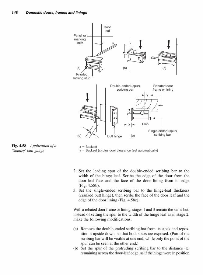
2. Set the leading spur of the double-ended scribing bar to the
width of the hinge leaf. Scribe the edge of the door from the
door-leaf face and the face of the door lining from its edge
(Fig. 4.58b).
3. Set the single-ended scribing bar to the hinge-leaf thickness
(cranked butt hinge), then scribe the face of the door leaf and the
edge of the door lining (Fig. 4.58c).
With a rebated door frame or lining, stages 1 and 3 remain the same but,
instead of setting the spur to the width of the hinge leaf as in stage 2,
make the following modifications:
(a) Remove the double-ended scribing bar from its stock and repos-
ition it upside down, so that both spurs are exposed. (Part of the
scribing bar will be visible at one end, while only the point of the
spur can be seen at the other end.)
(b) Set the spur of the protruding scribing bar to the distance (x)
remaining across the door-leaf edge, as if the hinge were in position
148 Domestic doors, frames and linings
Pencil ormarking
knife
Doorleaf
Knurledlocking stud
(a) (b) (c)
(d) (e)
Double-ended (spur)scribing bar
Butt hinge
x � Backsety � Backset (x) plus door clearance (set automatically)
Plan
Single-ended (spur)scribing bar
Rebated doorframe or lining
X
Y
Fig. 4.58 Application of a
‘Stanley’ butt gauge

as shown in Fig. 4.58d. In this way, the spur of the rear scriber is
automatically set to include door clearance between the door
face and rebate check when scribing from within the door frame
or lining rebate, as shown in Fig. 4.58e.
Jigs of this type are used in conjunction with a portable power router,
to recess the hinge leaf into a door edge and its casing or frame. They
may be purpose made or a proprietary product.
A purpose-made jig suitable for an internal door and its lining
(with planted rebate) is shown in Fig. 4.59. It consists of an MDF
or plywood running-board template with cut-outs to suit the
surface dimension of the hinge leaf plus, as shown in Fig. 4.60, an
offset to allow for the thickness of a guide-bush and cutter clearance
(see also Volume 1, Fig. 6.44). The jig is held secure to the door
with cramps via a timber apron runner fixed to the underside of the
running-board at a distance from the face to suit the hinge type. The
door likewise must be held vertically secure on its edge, whereas
the hinged side of the lining will require securing to the jig horizon-
tally. Each routed hinge-leaf recess will result in two rounded corners;
these can either be cut out square with a chisel, or by using a pro-
prietary corner chisel, which after positioning is struck with a
hammer.
Door hanging 149
4.14.3 Door hinge jigs
Note: This type of jig/template isgenerally only suitable where sev-eral doors of the same type are tobe hung
Cramp securingjig to door lining
Vertical section A-A(Door lining in place)
Vertical section A-A(Door in place)
A
A
Apron runner
MDF or plywoodrunning board
Cramp securingjig to door stile
Fig. 4.59 Isometric and sec-
tional details of a purpose made
door hinge jig

150 Domestic doors, frames and linings
Plywood template
Plywood template
Collet chuck
Baseplate
Template guide bush
Bit
Guide-bush
Cutter
Router base
Work piece
D
d
E �D�d
2
Fig. 4.60 Making provision for
the guide-bush and cutter when
out the template
Note: Correct PPE must be used as well as a suitable extraction system
Fig. 4.61 Using the ‘trend’
hinge template
The ‘trend’ hinge jig as shown in Fig. 4.61 is a portable metal template
for recessing the hinge leaf into the door edge and inside face of its
reveal (casing or frame) – it can be used for both standard and fire door
requirements.

Door sets 151
Figure 4.62 shows:
(a) the hinge-leaf aperture being set to length;
(b) the hinge-leaf aperture being set to width;
(c) how provision is made for depth of cut to accommodate the thick-
ness of leaf.
The construction, hanging and fitting of fire doors is strictly controlled
by current building regulations and fire doors are only constructed by
certificated manufacturers.
Once the door has been fitted the required hardware is as follows:
Hinges: these should have narrow leaves and be made of non-
combustible material (having a melting point higher than 800°C). The
positioning and number of hinges will depend on the weight of the
door and the registered fire door manufacturer’s specifications –
usually three is specified. Figure 4.63 gives an example.
Closer: all fire doors will require an approved self-closing device
(Figs 4.87 and 4.88). Rising butts (Fig. 4.76) are allowed for this pur-
pose only in certain situations.
Mortise locks/latches: like the hinges, these should be as slender and/or
low-mass as practicable, thus reducing the amount of metal which
will conduct heat in the event of a fire.
A door set can be regarded as an external or internal door which has
been matched to a frame or lining, assembled, and pre-hung under
factory conditions with all the necessary hardware – locks, latches,
etc. It will be delivered to site either fully assembled or packaged in
such a way that it can be assembled as and when required (Fig. 4.64).
(a) Setting the length (b) Setting the width (c) Setting the depth of leaf thickness
Fig. 4.62 Making preparations for using a ‘trend’ door hinge jig on a door stile
4.14.4 Fire doors (seesection 4.10)
4.15 Door sets
Note: Hardware should not inter-fere with intumescent strips but,where this is unavoidable, suchareas may be coated with an intu-mescent paste

152 Domestic doors, frames and linings
Because the door set may have been surface-finished in the fac-
tory (painted or polished), the use of detachable hinges such as the
‘snappinge’ – snap-in door hinge (Fig. 4.64). This snap-in mechanism
permits easy assembly and dismantling of door sets. The hinge knuckle
portion is housed in the door jamb, and the pocket into which the tongue
fits is housed into the door leaf as shown in Fig. 4.64a. Because the
pocket does not protrude beyond the face of the door, doors can be
stacked flat one upon the other without interference of the hinge
knuckles. Figure 4.64b shows how the hinge tongue is released from
its pocket when the door leaf is removed from its frame enables the
door leaf to be delivered at a later stage, thereby reducing the risk of
surface damage (see also Figs 4.71, 4.72 and 4.76).
Templates (profiles) 10 mm wider and taller than the door set are
built into the masonry to leave a slightly oversize opening on their
removal. Templates should be detachable, to facilitate removal.
Figure 4.65 shows two types of template. The system shown on the
left-hand side consists of a detachable framework lined with 12 to
Fire door
1982 × 762
15
02
00
22
5
Note: Position of hinges is an example only.
Follow fire door manufacturer’s
specifications
Fig. 4.63 Examples of position-
ing hinges on fire door
4.15.1 Framingopenings

Door sets 153
Jamb
Tongue of hinge component
DoorPush and snap-in
Releasing doorfrom frame
(a) (b)
Wall
Note: ‘Snappinge’ hinges are no longer in production
Door furniture and
glazing by others
Storey height unit
(Kit and ready-hung door set)
Door height unit
(Kit and ready-hung door set)
Snap-in hinges
Snap-in
hinges
Keep
Glazing beads
loose pinned
Fig. 4.64 Door set system
18 mm plywood of a width equal to the thickness of the wall plus any
plasterwork. The plywood liner is fixed to the blockwork, etc., as the
wall is being built, and acts as a profile for the plasterer. After the inner
framework is removed (when the masonry is complete), the plywood
is retained as a fixing for the door set.

154 Domestic doors, frames and linings
The system shown on the right-hand side of Fig. 4.65 involves remov-
ing the whole (detachable) template to leave an opening of fair-faced
blockwork, etc. In this case, the door frame or lining will need fixing
to the wall via pallets or plugs and screws. (Plastics plugs must not
be used as a fixing for a fire-door set.)
In the example shown in Fig. 4.65, the door set linings are made out
to suit various wall widths by using add-on extension pieces.
Plywood sub-liningPlywood
corner webslet into frameto maintain
wall-face line
BB
Cleat
Cleat
Cleat
AA
50 × 50Framework Folding wedges
Plywood webs
Mid-packing
50 × 50Distancepiece on
cleats
Folding wedges
Built-upblockwork
Built-upblockwork
Distance pieces
Blockwork BlockworkPlywood sub-liningfixed to blockwork
5 mm Tolerance
Extension linings to suitwidth of wall
Through fixings(gapped screws)
Fixed architraveDoor set entered from this side Door set entered from this side
Horizontal sections A-Aplywood template (profile) retained
as fixing
Horizontal sections B-Bwhole template profile removed
Profiles in position
Inner framework/profiles removed
Linings in position
x
Framework collapses inwards afterstriking cleats and distance pieces,and is lowered via folding wedges
x
Fig. 4.65 Forming openings for door sets

Domestic sliding interior doors 155
(i) If necessary, assemble the door set framework/lining (Fig. 4.64),
including one set of architraves.
(ii) Drill the door frame/lining to receive fixing screws – see Fig. 4.66.
(iii) Offer the frame/lining to the opening – the fixed architrave acts as
a check (restraint).
(iv) Level the head or transom rail – adjust the foot or framework
as necessary.
(v) Check for straightness and plumb.
(vi) Using the holes in the jambs, drill into the masonry. Insert plugs
and screws – see Chapter 3, Figs 3.33 and 3.34.
(vii) Position packings (Fig. 4.66a) behind all fixing points between
the back of the jambs and the wall. Tighten the screws. Check
with a distance piece or the door leaf (on drop-on or push-in
hinges) for correct clearances.
(viii) Remove the door leaf (if supplied). Plug all fixing points with
wood pellets or plastics caps, as shown in Fig. 4.66b.
(ix) Fix loose architraves on the opposite side (Fig. 4.67) and the
fanlight if fitted (see also section 8.2).
With the exception of stage (vi), the above fixing procedures will also
apply to timber-studded partitions.
Sliding a door across an opening provides a useful alternative to hin-
ging where floor space is restricted. There is, however, the disadvan-
tage that unless the door slides into a wall, surface wall space is lost.
There are several proprietary systems on the market. In the main, these
consist of an overhead track from which the door is suspended and
slide via a series of wheels made from plastics. The whole of the top
sliding gear is covered by a pelmet, which should be made detachable
Jamb orlining
X
Packing(plugging)
Pelletsmachined orhandmade
(a)
Fixing
Plastics cap – colouredto match wood finish
(b)
Wood anddirection of
grain tomatch jamb
Spotted withadhesive
Packings –purpose-madefrom hardboard
or plywood
Note: ‘X’ gaps around fire-resisting door sets (5 mm each side, 10 mm at head) to be plugged with mineral wool, intumescent mastic, or other non-combustible filler
Fig. 4.66 Fixing points for
frames, linings and door sets
Note: Fire-door sets should haveany gaps between the jambs and the wall plugged with a non-combustible filler as shown in Fig. 4.66
4.15.2 Fixing a door setinto masonry walls
4.16 Domesticsliding interiordoors

156 Domestic doors, frames and linings
to enable maintenance to the gear to be carried out without disturbing
any decorations.
The foot of the door may be grooved to receive a metal channel which,
as the door is slid open or shut, runs over a plastics guide-pin secured
to the floor.
Figure 4.68 shows a typical arrangement for sliding-door gear.
In large door openings it may be possible to have a pair of sliding doors
running on the same track and abutting when closed (see Chapter 10,
Joinery fitments).
Alternatively, instead of the doors running across the face of the
wall, they may disappear into specially constructed stud partitioning
either side.
Doors, their frames, and door sets should not be delivered to site until
they are required. If, on delivery, it is found that they have not been4.17 Storage andprotection
Corner mitre
Skirting boards abut
architrave
1
Head 1st jamb 2nd jamb Skirting board
2 3 4
Nailed mitre
Note: Fig. 4.67 gives a sequence of
fixing a standard architrave.
However, there are variations
to this method, therefore
see section 8.2
Fig. 4.67 Sequence of fixing architraves (see also Fig. 8.14)

Storage and protection 157
factory-sealed or primed, both faces and all four edges should be imme-
diately treated with the appropriate sealer or primer.
All doors awaiting use should be close ‘stacked’ (not less than three
bearers placed across the length of each door) and stacked flat (out of
twist) off the floor and under cover of a well-ventilated building.
Door stacks should have a dust cover, but this should not restrict
through ventilation. Doors which have been shrink-wrapped should
be left with the wrapping intact until required for conditioning (as
explained below at 4.17.2).
If polished or painted, jambs and linings are at risk of being damaged
by heavy and/or awkward objects (fittings and fitments) being rubbed
against them as they are being moved about the building. They should
be temporarily clad or boxed (see Chapter 3, Fig. 3.57) to a height of
not less than 1 m. Sills to exterior door frames which are continually
passed through by building operatives should be securely covered
with a detachable board.
Doors should be introduced slowly into the climatic conditions in
which they will remain. It is important, therefore, that interior doors
are not present in a building which is drying out after the operation of
any wet trade (laying concrete screeds or plastering, etc.), because of
the risk of high moisture intake into the wood.
4.17.1 Protection ofdoor framework
Lining
Architrave
Sectional plan
Plasterwork
Openposition
Front elevationDoor slides over or into wall
A B
Soffitlining
Optional plaster line
Channel (track)
Pelmit (detachable)
Heightadjustment
Door leaf
DoorMetal channel ploughed
into bottom of door
Nylon guide
Detail about‘A’
Detail about‘B’
Nylon roller
Fig. 4.68 Domestic sliding-
door gear
4.17.2 Conditioning

158 Domestic doors, frames and linings
In order for it to operate correctly, door hardware (often referred to as
‘ironmongery’) can be divided into four sections in relation to its use:
Length
Tee hinge (light-duty)
Scotch hinge (heavy-duty)
Fig. 4.69 Tee hinges
4.18 Doorhardware(ironmongery) Hardware Use
Hinges Door hanging devicesLocks and latches Door restraint and securityClosers Self-closing mechanismsDoor furniture Handles, knobs, letter-plates, etc.
The types of hinges available are varied depending on the type of door
to be hung. For a door such as a ledge-braced-and-battened door,
tee-hinges (Fig. 4.69) are used. They are formed from light gauge
metal and finished in a black epoxy lacquer, often referred to as
‘black-japanned’, or they may have a galvanized finish for extra pro-
tection. Two types are available (Fig. 4.69): the standard type for
lightweight doors, or the ‘Scotch’ hinge, which is more robust for
heavier doors such as garage doors. These are screwed to the face of
the door and frame, as the thickness of the door is insufficient to
receive a standard type hinge.
Thicker doors require standard cranked type hinges, which are housed
into the edge of the door and the inside edge of the frame and are
listed below.
A standard cranked steel butt hinge is shown in Fig. 4.70. The knuckle
of the hinge must protrude beyond the face of the door leaf and the
edge of the door jamb. Use 100 mm hinges on exterior doors and 75 mm
ones on interior doors.
Loose-pin butt hinge (Fig. 4.71): once the door leaf has been hung, it
may be detached from its frame by removing the pins from the hinge
knuckle – this is ideal for light-duty door sets.
Lift-off butt hinge or loose butts (Fig. 4.72): a medium-duty hinge
which enables the door leaf to be detached from its frame.
Cast butt hinge (Fig. 4.73a): made from cast-iron, this hinge is very
hardwearing and is classed as ‘heavy-duty’.
4.18.1 Hinges

Door hardware 159
Heavy duty stainless steel hinge with bearings (Fig. 4.73b): this type
of hinge is used in areas where there is likely to be above-normal
usage. For example, main entrance doors, etc.
Brass butts with phosphor bronze washers (Fig. 4.73c): again used in
areas of high use. The phosphor washers reduce the amount of ware
on the brass knuckles.
Hurlinge (Fig. 4.74): this light-duty butt hinge does not require housing
into the door or jamb; provided the correct screw size is used, the leaf
thickness of the hinge provides door clearance. Care must be taken
not to permit a build-up of paint around the hinge when painting, other-
wise a condition known as ‘hinge bind’ will result – this is when, on
Standard cranked steel butt
Doorleaf
Jamb
Standard fixing
Recess leafand jamb
Alternative fixing
Recess leaf only
Doorleaf
JambFig. 4.70 Standard cranked
steel butt hinge
Fig. 4.71 Narrow-pattern butt
hinge with loose cup-head pin

160 Domestic doors, frames and linings
closing the door, the hinge leaves touch before the door leaf is fully
closed.
Rising or skew butt hinge (Fig. 4.75a): this is a lift-off hinge with a
helical knuckle which causes the door to rise as it is opened. This
movement enables the bottom of the door to clear carpets, etc. and to
fall shut under the door’s own weight, thereby providing a simple
self-closing device.
Because the door starts to rise as soon as it is opened, the top inside
corner (hinged side) of the door will need to be slightly splayed, as
shown in Fig. 4.75b, to avoid catching the door head or transom rail.
Parliament hinge (Fig. 4.75c): a hinge that is used on a door frame
situated in a deep wall reveal. If a convential hinge were to be used,
the door would bind against the wall preventing it to be opened more
than 90°. A parliament hinge will allow the door to swing on a wide
radius, thus clearing the wall (Fig. 4.75d).
The disadvantage of this particular hinge is the projecting knuckles
when the door is closed. This may not only be unsighty but can
‘catch’ a person’s clothes whilst walking by.
Doorleaf
Jamb
Standard fixing
Recess leaf and jamb(Anticlockwise closing shown)
Alternative fixing
Recess leaf only(Anticlockwise closing shown)
Doorleaf
JambFig. 4.72 Lift-off butt hinge or
loose butts

Milledjoints
(a)
(b) (c)
Leaf
Jamb
Standard fixing
Recess leafand jamb
Alternative fixing
Recess leaf only
Milledjoints
Leaf
Jamb
Fig. 4.73 (a) Heavy duty cast
iron butts; (b) Double ball bear-
ings stainless steel hinge; (c)
Brass butt with phosphur bronze
double washers and brass pins
Jamb
Standard fixing
Doorleaf
Jamb
Doorleaf
Fig. 4.74 ‘Hurlinge’ hinge
(note: available with loose cup-
head pin)
Note: Care must be taken when fit-ting these hinges – although theyare very strong they are also quitebrittle and can be damaged ifstruck with a hammer.

162 Domestic doors, frames and linings
(a)
(b)
Clockwise closing doorshowing splayed corner
Door open
Hinge in open position
Doorclosed
Directionof hingeopening
Door jamb
Cover lath
‘Knuckle’
Brickwork
(d)
Doorleaf
Jamb
Standard fixing
Recess leaf and jamb(Anticlockwise closing shown)
Alternative fixing
Recess leaf only
Doorleaf
Jamb
Rising butt (handed)
(c)
Fig. 4.75 Clearance and projection hinges
4.18.2 Latches and locks
Hinge bolts (Fig. 4.76): The use of hinge bolts will prevent the door
from being forced of its hinges – particularly in outward opening
doors where intruders may try to remove the hinge pins to gain entry.
The bolt may take the form of a steel rod attached one hinge leaf
(shown in Fig. 4.76a), which engages into a hole in the opposite leaf
(attached to the door frame) when in the closed position.
Alternatively, other types include independent bolts (Fig. 4.76b) that
are secured both in the edge of the door and frame.
Once the door has been hung, the door schedule is consulted to deter-
mine which type of locking mechanism is to be used depending on
the type of door and its location.
Further subdivision will be necessary:
(a) thumb latch (Fig. 4.77);
(b) rim locks (Fig. 4.78b, also see Fig. 12.14a)

Door hardware 163
(c) cylinder mortise locks (Fig. 4.79f);
(d) mortise locks (Fig. 4.79);
(e) mortise latches (Fig. 4.80);
(f) cylinder rim locks (cylinder rim nightlatches) (Fig. 4.81).
4.18.2.1 Thumb latch (ledged-braced-and-batteneddoor) (Fig. 4.78) (also see Fig. 4.2)
The thumb latch, sometimes known as a Norfolk or Suffolk latch, pro-
vides a simple yet trouble-free means of holding a ledge-braced-and-
battened door closed whilst at the same time allowing it to be opened
from both sides. If, on the other hand, the door has to be fixed shut at
some time for security reasons, then the addition of a lock and/or bolt
should be considered.
It should be fixed in the following manner:
1. Make a slot in the door, into which the sneck is pushed;
2. Screw the face-plate (to which the sneck is hinged) to one face of
the door;
3. Fix the beam and keeper to the opposite side;
4. The stop can now be screwed to the frame.
The ledged-braced-and-battened door, because of it thickness com-
pared to standard doors, requires hardware that is fixed onto the face.
(a) (b) NB. All measurements are in millimetres
Fig. 4.76 Hinge bolts

164 Domestic doors, frames and linings
Probably the simplest way of making the door secure is by the use of
a tower bolt, screwed to the door’s ledge (see Fig. 4.78a).
To lock the door, a rim lock or rim dead lock (Fig. 12.14a) is used in
areas of security (Fig. 4.78b), which will require a keyhole to be
made in the door (Fig. 4.78c).
4.18.2.2 Lock/latch terminology
Backset (Fig. 4.82) The distance by which the vertical centre line
of the keyhole and/or spindle hole is set back from the front of the
outer forend.
Blank An unnotched key – see ‘Key blank’.
Beam
Sneck
Sneck
Stop
KeeperFace-plate
Handle
Fig. 4.77 Thumb latch (Norfolk
or Suffolk latch)
(c)
(a)
(b)
Keyhole
Remove withchisel
Staple/keep
Keep
Tower bolt
Rim lockFig. 4.78 Locks for ledged-
braced-and-battened door

Door hardware 165
(b) Deadlock (5 levers) –
for security
(c) Horizontal lock (5 levers) –
used with knob furniture
(d) Hook – bolt lock
(for sliding doors)
(e) Claw – bolt lock
(for sliding doors)
(f) Cylinder dead lock
(a) Upright mortise lock
(sash lock)
Fig. 4.79 Mortise locks
Bolt (Fig. 4.82) The part of the lock or latch which protrudes from
the case and enters a striking-plate or keep to lock or latch the door.
Case (Fig. 4.82) Contains the lock and latch mechanism.
Claw bolt (Fig. 4.79e) Sections of this bolt move sideways, dove-
tail fashion, as the bolt is shot (pushed out of its case via a key). It is
used on sliding doors.
Cylinder (Fig. 4.84) This houses the pin or disc tumbler and spring
mechanism. It may be round-faced or profiled.
Cylinder lock or latch (Figs 4.79f) A lock or latch which uses a
cylinder key mechanism (also available as an upright mortise lock
(sash lock)).
Deadbolt (Fig. 4.82) A square-ended bolt moved by a key.
Deadlatch (Fig. 4.81) A nightlatch with a spring bolt capable of
being locked with a key or catch.

166 Domestic doors, frames and linings
Tubular mortise latch (roller latch) Tubular mortise latch
General-purpose mortise latch
Fig. 4.80 Mortise latches
Double-locking nightlatch (spring-boltcan be deadlocked) (wide stiles)
Nightlatch (narrow stiles)
Twin-cylinder automatic deadlock
Fig. 4.81 Cylinder rim locks (cylinder rim nightlatches)

Door hardware 167
Deadlock (Fig. 4.79b) A lock with a square-ended bolt operated by
a key or thumb-turn.
Disc tumbler lock A cylinder lock with discs instead of pin tum-
blers (not dealt with in this chapter).
Double-handed lock A lock which, by being turned upside down,
can be used on either clockwise or anticlockwise closing doors. The
keyway has a hole at both ends of the slot.
Escutcheon (plate) A cover for a keyhole – part of the lock furniture.
Face-plate (the outer of a double forend) A cover plate fixed to the
inner forend.
Follower The part of the bolt mechanism which withdraws the spring-
bolt as it is turned. It may have one or more horns (see Fig. 4.83).
Forend (Fig. 4.82) Mortise lock or latch fixing plate.
Full-rebated forend (Fig. 4.85) A purpose-made forend or attach-
ment specially shaped for use either with a rebate in a door jamb or
(more likely) with door-to-door meeting stiles.
Handing (Fig. 4.53) With locks and latches, interior or exterior
operation may also be necessary.
Hook bolt (Fig. 4.79d) Used for securing sliding doors – as the
bolt (which is pivoted) enters the keep, it lifts up and then drops over
the keep.
Horizontal lock (Fig. 4.79c) This allows a greater distance between
the door edge and the spindle hole or keyhole. It is used with knob
furniture.
Keep or keeper Fixed on or into the door jamb to retain the bolt
(Fig. 4.78b).
Key See Fig. 4.83d.
Key blank A key sized to fit a keyhole, but not notched to suit the
locking mechanism.
Latch (Figs 4.80 and 4.81) A bevelled spring bolt, or a roller bolt used
to fasten a door. Certain types are lockable, e.g. nightlatches (Fig. 4.81).
Levers (Figs 4.83a and b) Flat shaped plates which form part of the
locking mechanism – the greater the number, the better the lock’s
security. Figure 4.83a shows their operation; Fig. 4.83b shows how
they are fitted within the lock case.
Lever handles (Fig. 4.91) Lock or latch furniture which operates
the spring bolt of a lock or latch.

168 Domestic doors, frames and linings
Lock (Figs 4.79 and 4.83b) A case containing a locking device,
usually operated by a key.
Locking latch (Fig. 4.81) A latch (spring bolt or roller bolt) cap-
able of being locked.
Lock set Matched lock and furniture (handles, spindle, escutcheon,
etc.) ready for fixing.
Mortise lock or latch (Figs 4.79 and 4.80) A locking or latching
device which is mortised into a door stile.
Narrow-case lock or latch A rim lock or latch suitable for narrow
door stiles.
Nightlatch (Fig. 4.81) A latch with a bevelled spring bolt or a
roller bolt, which automatically latches as the door is closed. The
latch may be withdrawn from its keep by a key from the outside or by
a knob or lever from the inside. Latches may also be retained within
their case, or deadlocked.
Pin tumbler mechanism (Fig. 4.84) A cylinder mechanism con-
sisting of a row of spring-loaded tumblers which rise and fall to meet
Fixing point
Live – orlatch – bolt hole
Lip
Deadbolt hole
Fixing point
Bullet
Keyhole (keyway)
Deadbolt
Spindle hole
Live or latch bolt
Follower
Single fore-end
Double fore-end
Backset
Fixing point
Fixing point
Backset
Overall size of lock
Case
Striking plate
Fig. 4.82 Mortise-lock components

Door hardware 169
SpringStud
Lever
KeyholeKey
Notch
(a)
Wards
(c) (d)
Bow
Shank
Collar
PinLever notchesor bitting
Blade
Ward notch or bitting
Bolt
Forend
Bolt
Bolt thrower
Brass levers withfalse notching
Hardened steelanti-drill plates(invincible only)
Horn
Slots to accommodatebolt through furniture
Spring
Hardenedsteel rollers
Easily reversiblelatch (no need toremove top plate)
(b)
Fig. 4.83 Mortise latch/lock mechanisms
the V-notches cut in the key. When all the junctions between pins (the
lower parts of the tumblers) and the drivers (the upper parts of the
tumblers) are aligned (by using a correctly cut key), the cylinder plug
can be rotated to operate the latch.
Plug (Fig. 4.84) The part of the cylinder into which the key is put.
It can be rotated when the correct key is used to allow the pins and
drivers to separate. It may also have a disc tumbler mechanism (not
dealt with in this chapter).

170 Domestic doors, frames and linings
Locked
Unlocked
Notchings or bittings
Blade
Fluting
Shoulder
Bow
Rim cyclinder(round face)
Profiled cyclinderFig. 4.84 Cylinders and their
operation
(a)(b)
(c) (d)(e)
(f)(g)
Rebatedmortise latch
Fig. 4.85 Full-rebate compo-
nents sets: (a) rebate in door
jamb, (b) striking-plate, (c) rim
section, (d) plain forend;
(e) mortise lock, (f) rebated
forend, (g) rebate in door

Door hardware 171
Rebated lock or latch (Fig. 4.85) A mortise lock or latch with a
full-rebated or adapted forend.
Reversible bolt A spring bolt which can be turned round to suit the
door handling. Caution The bolt is under pressure from a compressed
spring, and this spring can become dislodged if the case is opened. If
it is necessary to open the case, wear eye protection and carry out the
operation within a tall-sided open-top cardboard box.
Rim lock or latch A lock or latch which is screwed on to the face
of a door.
Roller bolt (Fig. 4.80) An alternative to a bevelled spring bolt – it
does not require handing.
Rose A plate which fits behind a cylinder or a door knob.
Sash lock (Fig. 4.79a) The same as an upright mortise lock.
Sash wards See ‘Wards’.
Shoot of a bolt The distance a bolt moves.
Skeleton key A key cut to suit a number of differently warded
locks, by bypassing the wards. (This is not possible with a cylinder
or levered lock.)
Spindle A square-sectioned steel bar which forms part of the lock
furniture. It passes through the follower and fits into a lever handle or
knob on each side.
Spring bolt (latch bolt) (Fig. 4.82) A bolt which is spring-loaded
to retain it in the extended position. One edge is bevelled to form a
lead to enable it to ride over its striking-plate before entering its keep.
It is operated by handles or knobs.
Spring-latch (Fig. 4.81) A latch with one spring bolt, operated by
a key from outside and by a knob from inside.
Staple A box-shape keep fixed to a door jamb to receive the bolt of
a rim lock or latch.
Striking-plate (Fig. 4.82) A metal plate let into and screwed to the
door jamb to shroud the mortise holes which receive bolts from mor-
tise locks and latches.
Tubular mortise latch (catch) (Fig. 4.80) A mortise latch which
fits into a single round hole.
Upright lock A mortise or rim lock with a narrow case to fit into
(sash lock) or on to the width of a door stile.

172 Domestic doors, frames and linings
Wards (Fig. 4.83c) Metal rings fixed to the inside of the lock case
such that a key must pass around them in order to operate the bolt –
often used with levers.
Warded lock A lock which relies solely on wards as a means of
security – suitable only where security is of little importance.
4.18.2.3 Fitting and fixing a mortise lock
(i) Determine the position (usually 900 m/m) of the spindle hole.
For asthectic reasons, locks fitted to multi-light doors should
have their spindle hole in line with the glazing bar nearest to
the middle of the door.
(ii) At a convenient open position, gently wedge the door to pre-
vent it swinging. (Overtightening will cause damage to the
door and frame, and possibly to the wall.)
(iii) Lightly mark the top and bottoms of the mortise hole (Fig.
4.86a) and transfer across the door edge (Fig. 4.86b).
(iv) With a marking gauge or combination square, gauge the centre
of the door leaf and the amount of backset (Fig. 4.86c).
(v) Measure and transfer to the door the distances down the back-
set line to the centres of the spindle hole and keyhole (Fig.
4.86d).
(vi) Bore the spindle hole and the keyhole as shown in Figs 4.86e
and f – from both sides of the door leaf.
(vii) With a chisel, cut out the keyhole from both sides of the door
leaf (Fig. 4.86g).
(viii) Using a bit with a diameter equal to the width of the lock case,
and a depth stop, bore a series of holes for the mortise (Fig.
4.86h).
(ix) Chop and clean out the mortise hole square – if a swan-necked
mortise chisel is available it is most useful for this purpose
(Fig. 4.86i).
(x) Position the lock in the hole. Mark around its forend (Fig.
4.86j), then chop out a recess in the door’s edge until the
forend fits flush. Screw the lock to the door.
(xi) Fit the spindle and handles to the door. Check that the spring
bolt and key operate.
(xii) Close the door. Mark the top and bottom of the latch bolt and
dead-bolt on to the face of the door jamb (Fig. 4.86k).
(xiii) Square across the rebate. Gauge distance ‘x’ (Fig. 4.86l). Chop
out the mortises in the jamb to form the keep.
(xiv) Adjust the mortise holes in the door jamb until the latch bolt
and dead bolt operate freely, then position the striking-plate
over the holes. Mark out the recess and chop out until the strik-
ing-plate is flush with the woodwork – screw back to the door
jamb.

Door hardware 173
X
Spindle hole
Key hole
Chop out waste
(a) (b) (c) (d)
(e) (f) (g) (h)
(i) (j) (k) (l)
Fig. 4.86 Fitting and fixing a
mortise lock
Door closers are mechanical devices which force or encourage a door
to close on its own. Some ‘push’, others ‘pull’, and rising butts (already
described under the heading ‘Hinges’) simply rely on the weight of the
door leaf. Methods of application vary – some are attached to the door
and/or the frame, some form part of the hinge mechanism, while
others are concealed.
Figure 4.87 shows examples of an overhead door closer that can be
used on either hand of door, and can be adapted to suit most hanging
situations. It contains a hydraulic check, adjusted by a turn-screw,
which prevents the door from slamming. Manufacturers fixing tem-
plate is also supplied with the unit.
The closer shown in Fig. 4.88 fixes on to the edge of the jamb and is
suited for doors up to 50 kg. The tension arm slides across a nylon
guide strip as the door is opened, and closes under pressure from a
coil spring in the tube. Pressure adjustment is made with a detachable
tommy (tension) bar, as shown in the diagram. This is screwed into
the closer and, in this case, rotated to the right to increase the tension.
The arm is then screwed into the left corresponding hole and, when
located back on the door, the tommy bar is removed. This is a simple
yet functional mechanism.
4.18.3 Door closers
Note: Caution: Manufacturers’instructions must be carefully readand understood. When charged(wound) these springs are under agreat deal of tension and thereforeconsideration must be given to the health and safety not only ofoneself, but also of others whomay be around.
Care must also be taken not toover-tension the spring, which maycause the gate to slam and causedamage or loosen the meetingpost.

174 Domestic doors, frames and linings
Door closer fittedto door with armfixed to face offrame head
Door closer fittedto door with armfixed to undersideof frame head
Door closer fittedto face of framewith arm fixed todoor
Fig. 4.87 ‘Briton’ overhead
door closer – three methods of
application

Door hardware 175
Figure 4.89 shows a concealed door spring which fits inside the edge
of the door and is attached via a chain to the door jamb. The mech-
anism is only visible when the door is open.
A ‘dictator’ door check is shown in Fig. 4.90a, which may be fitted
to the top of the door (other applications are available including hor-
izontal fixing). This is generally used with door closers shown in
Figs 4.88 and 4.89 to eliminate the ‘slamming’ action of the door,
which may lead to the frame becoming loose and the hinges being
damaged.
The hook is secured to the head of the frame to receive the wheel of
the ‘dictator’. As this wheel engages, hydraulic fluid contained in the
cylinder passes through a valve – this will dampen or slow down the
door as it engages into the hook. The ‘dictator’ door check is ideal for
situations where the door needs to be securely locked shut, for example
entrance doors to offices or flats.
When a pair of doors with rebated closing stiles are used, together
they will be required to close in the correct sequence. For this reason,
a door selector can be used (Fig. 4.90b). This ensures that the door
with the leading edge will always end up in its correct final position.
Again with the assistance of the door closers shown in Figs 4.87,
4.88 and 4.89.
Door furniture consists of those items of hardware which are fixed
either directly or indirectly to the face of a door and/or its framework.
Manufacturers often divide such items into the following groups:
(a) Lever furniture (Fig. 4.91)
}or{Lock and/or latch
furniture; or
(b) Knob furniture (Fig. 4.92) Mortise-lock and rim
lock furniture;
(c) Letter-plates, postal knockers (Figs 4.93 and 4.97c);
DoorPlanted
door stop Frame jamb
‘Tommy’ barremoved after
adjustment
Tensioned
Closer arm
Direction of door
• Adjustable tension• Max door weight 50 kg
Roller wheels in motionwhen door is opened
and closedHole for
‘Tommy bar’
Plate fixed to door
Fig. 4.88 ‘Gibralter’ door closer
4.18.4 Door furniture

176 Domestic doors, frames and linings
Fits into doorTension retained plate
screwed to jamb
Doorleaf
Doorjamb
Fig. 4.89 ‘Chasmood adjunct’ door closer
(d) Finger and kicking plates (Fig. 4.94);
(e) Door handles and pulls (Fig. 4.95);
(f) Security furniture (Fig. 4.96);
(g) Sundry items of furniture (Fig. 4.97).
Figure 4.97 gives examples of sundry items of door furniture:
(a) Proprietary door stops are used to protect the wall and to prevent
straining the hinges if opened too far.
(b) Shows one type of door coat hanger, but this may also make up a
number of hangers on a board fitted to the door or wall.
(c) Shows a letter plate with anti-draught flap, similar to Fig. 4.93.
(d) Shows two types of bell push: the conventional battery/
transformer type, and the other a solar powered. The ring box may
be located anywhere within the dwelling without the need for
wiring.
(a) (b)
Frame head
Hook
Door
Fig. 4.90 Door checks. (a) Dictator door check; (b) ‘Union’ door selector

Door hardware 177
Interior door Exterior door
Latch lever handle Lock lever handleFig. 4.91 Lever furniture
Keyhole escutcheon
Flap
Knob
Spindle
Rose
Fig. 4.92 Knob furniture
Fig. 4.93 Combined
letter-plate/postal knocker

12mmBody dia
Door viewer
Indicator bolt
25 mm
to
55 mm
Barrel bolt
Door chain (alarm chains available)Fig. 4.96 Security furniture
Finger plate
(metal or plastics)
Kicking plate
(metal)
Fig. 4.94 Finger and kicking
plates
Cylinder pull
(for night cylinder latch) Bar pullFlush pull
(for sliding doors)
Fig. 4.95 Door handles and
pulls

Door hardware 179
(a)
(b) (c)
(d)
Skirting board door stops Floor door stop
Hat and coat hook Letter plate with anti-draught flap
Bell push (labelled) ‘Solartone’ door bellpush (solar power)
Fig. 4.97 Sundry items of door furniture
References
BS 459: 1988, Specification for matchboarded wooden door leaves for
external use.
BS 6206: 1991, Impact performance.
BS 6262–4:1994, Glazing for buildings. Safety related to human impact.
BS 8214: 1990, Code of practice for fire door assemblies with non-
metallic leaves.
BS 5588–0:1996, Fire precautions in the design, construction and use
of buildings. Guide to fire safety codes of practice for particular
premises/applications.
BS 6206: 1981, Specification for impact performance requirements for
flat safety glass and safety plastics for use in buildings.
BS 6262: 1982, Code of practice for glazing for buildings.
BS 544: 1969, Specification for linseed oil putty for use in wooden
frames.
BS 952–1:1995, Glass for glazing. Classification PAS 23.
Building Regulations Approved Document B, Fire Safety: 2000.

Garage doors are much the same in their construction as some exterior
house doors (see Chapter 4). The main door openings are of course
wider, and doors are therefore hung in pairs, unless a one-piece door
is used, in which case it would be of the ‘up-and-over’ type or made to
slide. (Large sliding and folding-leaf doors are outside the scope of
this book.) See Work Activities – by Brian Porter & Reg Rose
Chapter 6. Table 5.1 shows common sizes that are available.
Because these doors are made to open outwards and are often left
open for long periods, provision should be made in their design and
construction for all-round protection against the weather.
Only three types/systems are to be considered here:
(i) ledged-braced and battened double-leaf doors;
(ii) framed-ledged braced and battened double-leaf doors;
(iii) ‘up-and-over’ single-door systems.
Methods of construction and hardware for these doors are shown in
Chapter 4. Each door is side-hung either with Scotch-tee hinges (see
Fig. 4.69) or with bands and hooks (crooks) (see Fig. 5.3), which offer
greater security and longer service. General security can be provided
Domestic garagedoors
5
5.1 Garage doortypes
5.1.1 Ledged-and-braced batteneddouble-leaf doors (Fig. 5.1)
Table 5.1 Garage doors (nominal door opening size)
Height Width Thickness
Double-leaf side-hung wood garage doors6�6� (1981) 7�0� (2134) 13⁄4� (44)7�0� (2134) 7�0� (2134) 13⁄4� (44)

Fitting and hanging hinged doors 181
by two tower bolts (see Fig. 5.4) – one at the top, the other at the bottom
of the inside face of the door – and a rim deadlock.
If, due to the door’s width, brace lines (sag bars) are at an angle of less
than 45° to the horizontal, then a two-piece (via the middle ledge)
single brace may be adopted as shown.
Where doors meet, a cover lath is fixed (screwed from the inside of the
door) to the door leaf which is to receive the lock. This forms a door-
handing rebate.
Construction details are shown in Fig. 5.2. These are heavier and
stronger doors than those shown in Fig. 5.1 and usually require
stronger hinges, i.e. bands and hooks. Glazed panels may be included
in the design as shown in Fig. 5.2. Meeting stiles can be rebated from
the solid, or the doors may be reduced in width to accept two planted
staff beads (the former method is better where security is of special
importance).
Before starting, check the door opening for plumb and square-
ness and that it coincides with the door sizes (use a lath or
pinch rod).
Blocking at top andbottom for tower boltsAlternative brace line
A A BOutside elevation Inside elevation
Rim deadlock
Tower boltLedges
ex. 25 × 150Tee hinge
Door jamb
Brace ex. 25 × 100
Horizontal section A-A
16 mm matchboard
Horizontal section about B
Cover lathex. 25 × 75Fig. 5.1 Ledged-and-braced
battened double-leaf doors
5.1.2 Framed-ledgedbraced and batteneddouble-leaf doors (Fig. 5.2)
5.2 Fitting andhanging hingeddoors
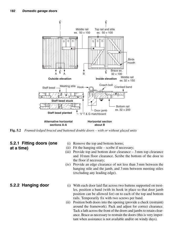
182 Domestic garage doors
(i) Remove the top and bottom horns;
(ii) Fit the hanging stile – scribe if necessary;
(iii) Provide top and bottom door clearance – 3 mm top clearance
and 10 mm floor clearance. Scribe the bottom of the door to
the floor if necessary;
(iv) Provide an edge clearance of not less than 3 mm between the
hanging stile and the jamb, and 3 mm between meeting stiles
(excluding any leading edge).
(i) With each door laid flat across two battens supported on trest-
les, position a band (with its hook in place so that door jamb
position can be allowed for) on to each of the top and bottom
rails. Temporarily fix with two screws per band.
(ii) Position both doors into the opening (provide a check (restraint)
around the framework). Pack and adjust for correct clearance.
Tack a lath across the front of the doors and jambs to retain clear-
ance. Brace as necessary to restrain the doors (this is very impor-
tant when assistance is not available and/or on windy days).
Middle railex. 50 × 150
BAABrace ex.32 × 100
Middle railex. 32 × 150
HookCoach bolt
Staff beadMeeting stile
Staff bead stuck
Staff bead planted
Cranked band
Birdsmooth
Bottom railex. 32 × 200Door jamb
Alternative horizontalsections A-A
Horizontal sectionabout B
CL CL
CL CL
Outside elevation Inside elevation
Top rail and stileex. 50 × 100
‘V’ T & G matchboard
Fig. 5.2 Framed-ledged braced and battened double doors – with or without glazed units
5.2.1 Fitting doors (oneat a time)
5.2.2 Hanging door

Hardware 183
(iii) Slide the pin of each hook into the band loops. Temporarily fix
with two screws per hook.
Note: Because each pin is a loose fit within its loop, the top hooks
should be lightly pushed away from the door as they are being
fixed; conversely, the bottom hooks should be pushed towards
the door. In this way, and provided the shoulders of the pins were
held tightly up against the bottom of each band loop, the door
should not drop or fall out of plumb when the door packings are
eased and then removed together with the front distance lath.
(iv) After removing the packings, etc., lift the doors off their hinge
pins (hooks). Lay them flat once more and, dealing with one
band at a time, mark the position of the coach bolt (a bradawl
may be used for this purpose) then remove the band. Bore a
hole to receive the bolt, paint the back of the band and its door
position, then fully fix the band back on to the door, including
the coach bolt, not forgetting to use a steel washer behind the
nut (see Volume 1, pages 167–8). This procedure should be
repeated with all the bands.
(v) Adopt a similar procedure with each hook but, before remov-
ing it from the jamb, gently tap the base of each pin (collar) so
that an impression is left on the jamb where the pin was
welded to the back-plate. Any protruding bits of metal can be
let into the jamb by cutting a shallow sloping groove with a
chisel – alternatively a hole may be bored, provided it slopes
upward to prevent water from lodging behind the crook. Only
two screws per hook should be used at this stage.
Note: It is important that, after the bands and hooks are
removed at stages (iv) and (v), they are returned to their origi-
nal positions. If, as mentioned, each one is dealt with sepa-
rately, mistakes will be avoided.
(vi) Seal the bottom edge of the doors by painting and/or treating
with preservative. Particular attention should be paid to the
end grain of the stiles.
(vii) Rehang the door. Check for all-round clearance and for twist.
Small amounts of twist may be removed by recessing the
back-plate of the offending hook or hooks (diagonally oppo-
site) into the jambs.
(viii) Fit and fix stop laths and a threshold as necessary.
(ix) Fix remaining hardware – security and stays, etc.
(x) Glaze as necessary.
Hardware for side-hung garage doors can be divided into the
following:
(a) hinges;
(b) security;
(c) door stays.
5.3 Hardware

184 Domestic garage doors
Fig. 5.3 Cranked band and hook
Fig. 5.4 Tower bolt Fig. 5.5 Garage door bolt
(adjustable ‘drop’ bolt)
Fig. 5.6 Bow or
D-handle bolt
Fig. 5.7 Monkey-
tailed bolt
Tee hinges are dealt with in Chapter 4, section 4.18.1.
A cranked band and hook is shown in Fig. 5.3. The crank (bend) in
the band (strap) enables the face of the door to be in line with the front
edge of its jamb. When the door is in the open position, it can be
lifted off its hinges – this useful feature permits easy access for main-
tenance; for example, all future painting can be done under cover.
Added security can be achieved by replacing the screws which attach
the hooks to the jambs with clutch screws.
5.3.1 Hinges

Hardware 185
One door leaf will be held shut by bolts. The most common type of
bolt, and the least expensive, is the tower bolt (Fig. 5.4). Figure 5.5
shows a much larger version known as an adjustable ‘drop’ bolt.
Stronger and heavier bolts such as the ‘bow’ or ‘D-handle’ bolt (Fig.
5.6) and the ‘monkey-tail’ bolt (Fig. 5.7) generally have handles
within easy reach of the operator, thereby avoiding any over-reaching
or bending. These heavy-duty bolts are square in section and spring-
loaded to prevent them dropping when used vertically at the top of
the door.
An alternative bolt for the bottom of the door, which is also operated
without bending, is the foot bolt (Fig. 5.8). As its name implies, this
is shot by pushing down with the foot. The bolt is retracted by press-
ing down on the side pedal.
The other door leaf can be held closed by a rim deadlock (see Fig.
12.14a) or a padlock with a hasp and staple. The type shown in Fig. 5.9
has a floating staple to compensate for any moisture movement, and
all its fixing-screw heads are concealed when fastened.
Stays provide a means by which garage doors may be safely held open
(at at least 90° to their opening). The door already fitted with a bolt
may be provided with an extra keep for when the door is open, and a
further bolt may be added to the foot of the adjacent door. If the doors
hinge back to a wall or fence, probably the simplest and most effective
means of providing a stay is by using two cabin hooks (Fig. 5.10).
Fig. 5.8 Foot bolt Fig. 5.9 Hasp and staple
5.3.3 Stays
5.3.2 Security (bolts)

186 Domestic garage doors
Failing that, the most satisfactory method – shown in Fig. 5.11 – is to
use two Crompton garage door holders; their automatic check secures
the doors in the open position. The doors are closed by simply releas-
ing the catch by pulling on the acorn pendants, then closing the doors
by hand. At no time should the cords be used to close the doors.
These doors are more likely to be made from galvanized steel, alu-
minium, or GRP (glass reinforced polyester) than timber, but the great
advantage that the timber door has over the others is that purpose-
made sizes are easily constructed. Generally accepted door-opening
sizes for these one-piece doors are shown in Table 5.2.
For fixing detail see Fig. 6.13Fig. 5.10 Cabin hook and staple
View outside with door open View inside with door shut
Standard fixing
DoorA
BLintel
Fig. 5.11 Garage door holder
5.4 ‘Up-and-over’single-doorsystems

‘Up-and-over’ single-door systems 187
Figure 5.12 shows two possible types of door. Fig. 5.12a uses a
framed-ledged-and-braced battened method of construction, whereas
Fig. 5.12b has a solid-timber outer frame with a central muntin and
midrails. For the sake of appearance, the outer surfaces of the two
exterior-grade plywood panels have been subdivided by two false
muntins.
When these doors are fully open (overhead), their own dead weight
makes them inclined to sag across their width. This deflection can be
overcome by fixing a purpose-made brace longitudinally along each
rail. These braces may be available from the door-gear manufactur-
ers (Fig. 5.12i), but possible alternatives are shown in Fig. 5.12ii – iv.
‘Up-and-over’ gear must match the door’s weight and material and
may be fitted by a number of methods including:
(i) Canopy;
(ii) Tracked;
(iii) Optimizer.
Figure 5.13 shows the principle by which these door systems operate:
(i) Canopy (Fig. 5.13a): a common system suitable for most wood
doors, which when in the open position leave one-third of the
door protruding (providing a canopy).
(ii) Tracked (Fig. 5.13b): includes horizontal tracks secured to the
wall or ceiling to support and allow the door to retract com-
pletely back into the garage.
Table 5.2 Door-opening sizes for singleleaf up-and-over garage doors
Width Height
6�6� (1982) 6�6� (1982)6�6� (1982)* 7�0� (2134)7�0� (2134) 6�6� (1981)7�0� (2134)* 7�0� (2134)7�6� (2286) 6�6� (1982)7�6� (2286) 7�0� (2134)8�0� (2438) 6�6� (1982)8�0� (2438) 7�0� (2134)9�0� (2743) 6�6� (1981)9�0� (2743) 7�0� (2134)14�00� (4265) 6�6� (1981)
* Most common sizes
5.4.1 Door-gear

188 Domestic garage doors
(iii) Optimizer (Fig. 5.13c): the lifting gear is secured to the door
frame with the tracks on the door – which eliminates the need
for horizontal tracks.
Figures 5.13b and c are recommended for double size doors of tim-
ber, metal or GRP, with the addition of remote control. Sliding and
folding door gear is shown in Work Activities, B. Porter and R. Rose
(2004) Elsevier, Chapter 6.
Adjustment
Outside elevation
Outside elevation
Inside elevation
Inside elevation
(i) Steel (TIE) brace
(a) Framed-ledged braced and battened door
(b) Framed and panelled door
(ii) Metal angle
(iii) Metal channel
A A Brace line
(iv) Hardwood back rail (stiffener)
Part elevation
Rail
Muntin False muntin Stile
Ext. grade plywoodSection A-A
In the horizontal position, deflection will occur due to the dead weightof the door, restraint can be offered by using cross-members
Fig. 5.12 ‘Up-and-over’ single-
leaf garage doors
Note: Unless ordered separately,hardware for up-and-over doorscomes complete with the operat-ing gear – see manufacturers’ catalogues.

Surface finish 189
Sliding garage doors are usually purchased ‘self finished’, which
means they have been coated in a suitable protective coating against
the elements. Depending on the material of the door, this coating is
built up in layers and may be classified as low to high build as seen in
the following examples:
(i) Timber
Paint – exterior paint (medium/high build) includes primer, under-
coat and finish coat in matt or gloss.
Stain – either spirit, water or oil based (low build) and available as a
semi-transparent coloured coating applied to hardwoods or softwoods
to enhance the grain of the timber.
Varnishes – (low build) include syntectic, copal and water thinned –
contain PVA which is low odour and quick drying.
Note: Micro-porous stains maycontain fungicides. They can alsooffer resistance to ultra-violet raysthat otherwise could lead to theeventual breakdown of their pro-tection (see vol. 1, Chapter 2)
Note: See Section 2.6 regardinghigh/medium and low finishes.
Canopy
Tracked
Optimizer
A spring above the doorprovides the tension
needed to help the doorto open and close
The door opens into thegarage along horizontal
tracks
Side springs help the doorto open and close smoothly
The tracks are fitted tothe side of the door
Side springs help the doorto open and close smoothly
(a)
(b)
(c)
Fig. 5.13 ‘Henderson’ operating
gear for ‘up-and-over’ doors
5.5 Surfacefinish

190 Domestic garage doors
References
BS 459: 1988, Specification for matchboarded wooden door leaves for
external use.
BS 6262: 1982, Code of practice for glazing for buildings.
BS 544: 1969, Specification for linseed oil putty for use in wooden
frames.
BS 952–1: 1995, Glass for glazing. Classification.
Building Regulations Approved Document B, Fire Safety: 2000.
BS 1282: 1999, Wood Preservatives. Guidance on choice use and
application.
BS 4261: 1999, Wood Preservation, Vocabulary.
BS 5589: 1989, Code of practice for wood preservation.
BS 5268–5: 1989, Structural use of timber, code of practice for the pre-
servative treatment of structural timber.
BS 5707: 1997, Specification for preparations of wood preservatives in
organic solvents.
BS 7956: 2000, Specification for primers for woodwork.
BS 6150: 2005, Code of practice for painting of buildings.
BS 7664: 2000, Specification for undercoat and finishing paints.
BS EN ISO 4618–3: 2000, Paints and varnishes. Terms and definitions
for coating materials. Surface preparation and methods of application.
BS EN 12051: 2000, Building hardware.
BRE Digest 301: 1985, Corrosion of wood by metals.
(ii) Steel
Usually galvanized and finished with coating of polyester powder (high
build) which has been baked on during the manufacturing process.
(iii) GRP (glass reinforced polyester)
Includes a smooth gloss or simulated timber finish which is almost
maintenance free.

Gates are means by which persons and/or vehicles can pass through
what could otherwise be a physical barrier to a property or area. The
degree of security offered by a gate will depend on:
(a) its type;
(b) its method of construction;
(c) its height;
(d) its ability to be locked.
The importance of the above will greatly depend on the purpose of the
gate. For example, the security of a garden, driveway, side, or yard gate
for a domestic dwelling will eventually be at the discretion of the
house owner; on the other hand, commercial and industrial premises
will require their gates to be heavily secured as and when required.
These latter types of gate are outside the scope of this book. However,
they may resemble hinged solid garage type doors shown in Chapter 5.
These gates are not usually wider than 1 m and, unless a visual barrier
is required, are generally slatted so that wind pressure is less of a prob-
lem and water is driven off their surfaces more quickly.
Figure 6.1 shows three examples of slatted gates. All have been
designed in such a way that their upper surfaces are either sloping or
covered by a weathered capping to discourage water from lying upon
them. The greatest danger from wet rot is where palings lap rails and
braces and abut ledges or rails. Particular attention to pre-painting/
preserving is important around these areas.
As shown in Fig. 6.1 gates (a) and (b) can be made up of a mortised-
and-tenoned framework. Joints should be either wedged and glued
(with exterior-type resin adhesives) or painted and pegged (dowelled).
Alternatively, a ledged-braced-and-paled construction could be used.
Gate (c) must be framed, braced, and paled. Gaps between palings
should be narrow enough to prevent a toe-hold, thereby preventing
Domestic gates6
6.1 Singlepersonnel-accessand garden gates

rails being used as a ladder and discouraging children from swinging
on the gate.
Where the gateway serves only vehicles, it is worth considering a
wide single gate. On the other hand, if it is to double as a garden gate,
two (double) gates would be more practicable – regularly opening
and closing a wide gate can be awkward and difficult.
Figures 6.2 and 6.3b show a modified field gate. Its design lends itself
to having a personnel gate to open across one-third of the overall
opening width to give greater ease of access. However, such arrange-
ments are not always practicable with openings wider than 2.4 m, as
the gate stop and/or bolt keep could interfere with vehicle tyres.
Figure 6.3a shows one of a pair of traditional-type double garden gates.
Both gates are capable of being swung, but one is usually kept ground-
bolted until vehicle access is required. The bolt (see Figs 5.4 to 5.8)
is shot into the driveway via a protruding timber, metal, or concrete
gate stop, which can be a hazard when both gates are open.
To give the appearance of a traditional field gate, an extended cruck
(bent) stile has been used. In Fig. 6.3c and d this serves as a straining
anchor for the through or cross-tie; but in Fig. 6.3b, although functional,
it is mainly ornamental.
Timber for the cruck stile would have originally been taken from nat-
urally bent wood. Today, this design is copied by laminating timber
to whatever shape is required.
192 Domestic gates
6.2 Domesticvehicle- andpersonnel-accessgates
A Capping coversend grain
Drip grooveVertical section
through B
Vertical section through A
Vertical section C-C
Brace
CB
D
(a) (b) (c) C Pale
Top rail
Decorativestile end
LedgeBare-faced tenon
Stile Palings
Alternative horizontal sections through D
Bottom rail
Fig. 6.1 Single personnel-
access and garden gates

Domestic vehicle- and personnel-access gates 193
Fig. 6.2 Modified field gate to
include personnel access
(a) Double gates
(b) Field-type gate (double gate)
(c) Five-bar field gate
(d) Modified field gate
Gate stoptimber (preserved),concrete, or metal
Ornamental cruck(laminated timber)
W
Tie
Tommy bar fortightening strainer
12 mm dia.steel straining tie
Centre straineror tapped tube
Weldedplate – ornut andwasher
Tie
Bolt keep(steel tube)
Bolt, washers, andtimber connectors
W13 W
23
Rail
Upright
Fig. 6.3 Domestic vehicle- and
personnel-access gates

Meeting stiles for the gates should be dealt with as shown in Fig. 5.2
(garage doors).
Figure 6.3c shows a five-bar field gate of simple construction. The top
rail and stiles – one of which is extended, either straight or as a lam-
inated cruck – are made from 75 mm thick timber. Mid-rails (mortised
into the stiles), the upright tie, and the brace can be bolted together with
timber connectors (Volume 2, p. 145, Fig. 8.21) where they intersect.
Figure 6.3d shows a fully framed five-bar gate with a tie made from
end-tapped steel rod. The rod passes through the gate and is anchored
by a plate and nut under the bottom rail. Tension adjustment can be
made via the plate and nut sited on the hanging edge of the cruck.
Alternatively, tension can be achieved via a mid-strainer made from
a piece of internally tapped steel tube.
Gates can be hung from brick walls or pillars (Fig. 6.6), concrete
posts (Fig. 6.7), or timber posts (Fig. 6.8). Each should be plumb and
well anchored to the ground or substructure.
The procedure for hanging gates differs from that already mentioned
for garage doors only in the amount of clearance left. Between the
gate and its post, 12 mm clearance is allowed for face-hung gates –
the gap for gates hung on hooks between posts will depend on the
hook protrusion. Floor clearance may be as much as 75 mm.
If a driveway or path slopes towards the swing of the gate or gates,
there are three methods of dealing with the situation, depending on
the amount of slope:
(i) use double gates with sufficient gap under the gates to clear the
ground when fully open (Fig. 6.4a),
(ii) level sufficient of the driveway to allow the gates to open fully
(Fig. 6.4b),
(iii) use purpose-made offset (cranked) bands and hooks at the bot-
tom hinge positions – these will enable the gate or gates to tilt
upwards as they are opened (Fig. 6.4c).
If the outside pavement is sloping and the driveway is in line with it,
as shown in Fig. 6.5, one end of the gateway will be higher than the
other. Provided the rails of the gate are level, the stiles and palings
may be extended accordingly (see Volume 2, p. 20, re datum lines.)
In the main made from ferrous metals (containing iron) that are not only
subjected to rusting, but may also be in danger from corrosion which can
194 Domestic gates
6.3 Gate hanging
6.3.1 Sloping paths
6.3.2 Gate hardware(ironmongery)
Note: Where hinges are face-fixed,a certain amount of lift can be cre-ated by chopping the top back-plate of the hook into the post andpacking out the bottom; however,gates will not be plumb when theyare closed. Similarly, gates hungbetween posts can have theirhooks fixed out of plumb, and inthis way the gate can be made totilt upwards as it opens

be accelerated by the acid condition of certain woods, which becomes
active as their moisture content is increased (see Volume 1, page 50(g)).
Under normal conditions ironmongery (to a certain extent) can be pro-
tected by painting, but if acidic conditions do exist – such as when
using English oak or western Red Cedar – then ironmongery should be
galvanized or black-powered coated to prevent direct contact, as paint-
ing provides only short-term protection (see Volume 1, Chapter 3).
Hardware falls into the following categories:
● hinges;● catch or latch mechanism;● bolts and stays.
Gate hanging 195
(a)
PavementGate Slope of driveway/path
Drive flattened
(b)
Pave
ment
Slope of driveway/path
Plan of driveway
Gate lifted to slope of drive
Undersized pin allowsfor movement
Offset band and hook(c)
Level
X
Note: Top and bottom of gates should be level, if necessary, tapered gap ‘X’ may be added to bottom of gate, but bottom rail of gate should still be level
Slope of street
Fig. 6.4 Dealing with a sloping
path or driveway
Fig. 6.5 Dealing with sloping
street pavements

6.3.2.1 Hinges
Figure 6.6 shows a double-pronged hook, which is secured in the
brickwork to receive a straight (uncranked) band type that is to be
fixed to the face of the gate.
Figure 6.7 shows two methods of securing a hook and plate, either
direct to the timber post or to the concrete post via a timber facing.
Notice that the timber batten has been splay cut on one end to assist
with dispersing any surface water.
Heavy gates of wider sectioned timber will require a double-strap (or
band and crook) field-gate hinge and hook bolt as shown in Fig. 6.8.
(The long band via both sides of the top rail, the short band towards
the bottom of the stile.) Both are held in place to the gate via coach
bolts and screws. The top hook is bolted through the gate post, as it
will be in tension; the bottom hook can be driven into the gate post as
this will be in compression. The thickness of the gate fits between the
strap and is secured through the gate with coach bolts. The hook may
be driven or bolted into the post.
196 Domestic gates
Note: The hinge ‘band’, togetherwith its ‘hook and plate’, is some-times collectively referred to as a‘band and crook’
Curled eye, straight band
See also Fig. 6.7
Masonry wall
Timber facing (50 × 100) boltedto concrete post
Cranked band (see Fig. 5.3)
Timber post
Concrete post(reinforced)
Hook on plate
Fig. 6.6 Double-pronged hook
to brickwork
Fig. 6.7 Hook and plate to
timber gate post or timber facing
to concrete gate posts

6.3.2.2 Catch or latch mechanism
Of the many examples, three are listed below:
● automatic gate catch (Fig. 6.9);● spring-loaded automatic gate catch (Fig. 6.11);● throw-over gate loop (Fig. 6.12);● thumb-latch – see Fig. 4.77 (also known as Norfolk or Suffolk
latch).
Automatic gate catch
Probably the most efficient catch for narrow gates is an automatic
gate catch like the one shown in Fig. 6.9 – except for the occasional
drop of oil on the speck pivot, it is maintenance-free. The malleable
iron peg is screwed to the opening gate, and the speck case is screwed
either to the gate post (with a single gate) or to the static gate (held
closed by a ground bolt) of double gates.
It is important that an automatic gate catch is accompanied by a stop
lath (Fig. 6.10) or some other form of gate check, otherwise the peg
will become dislodged after a short time.
Tall gates will require a means of latching accessible from both
sides. A thumb-latch (Chapter 4, Fig. 4.77) would be ideal for this
Gate hanging 197
Timber gate post
Long band
Short band and drive hook Hook to bolt
Fig. 6.8 Double-strap field-gate
hinge and hook bolt – for heavy
gates
Fig. 6.9 Automatic gate catch

purpose – possibly with the addition of a horizontally fixed tower bolt
(Chapter 5, Fig. 5.4) for added security.
Spring-loaded automatic gate catch
Figure 6.11 shows another type of automatic gate catch that is acti-
vated via a spring-loaded rocker arm with rubber rotatable wheels at
either end. It is activated when struck by the striker-plate attached to
the closing stile – usually in line with the top rail of mid-height gates.
Figure 6.11a shows the rocker arm about to be struck in the open
position. Figure 6.11b on the other hand shows the gate closed with
the catch in the closed position. Figure 6.11c gives a vertical view
behind the gate, with the gate and catch closed.
However, single modified field gates will require a more substantial
means of latching to hold the gate closed (see Fig. 6.12).
198 Domestic gates
Gate postGate stop(stop lath)
Gate
With gate stop (in check) Without gate stop (un-checked)
Gate post
Gate stileStop lath
Gate post
Gate stile
Stop lath
Striker-plate
Spring-loadedautomatic catch
(a) Horizontal section through gate post and gate (in the open position)
(b) Horizontal section through gate post (in the closed position)
(c) Vertical elevation
Weatheredgate post
Spring-loadedautomatic gate
springStriker-plate
Plan view
Gate stile
Plan view of ‘stricking’ plate
Fig. 6.10 An automatic gate
catch in check
Fig. 6.11 Plan view of spring-loaded automatic gate catch

Throw-over gate loop (Fig. 6.12)
Where such a gate incorporates a personnel gate (Figs 6.2 and 6.3b), a
‘throw-over gate loop’ is usually used (see Fig. 6.12). This is bolted
to the personnel access gate and loops over the secured field gate. When
lifted, it allows the gate to be opened separately, allowing entry.
6.3.2.3 Anchor bolts and stays
There are various methods used to allow the gate to be held either in
the open or closed position.
For example:
● Tower bolt (see Figs 5.4 and 4.78);● Adjustable ‘drop’ bolt (Figs 6.12 and 5.5);● Cabin hook and staple (Figs 6.13 and 5.10);● Gate holder (Fig. 6.14);● Gate spring (Fig. 6.15).
Tower bolt
Secured vertically or horizontally to the stile of a medium sized gate, its
purpose is to hold it in either the open or closed position (see Fig. 5.4).
Gate hanging 199
Throw-over loop radiates up
Weathered top railThrow-over loop
secured to top railwith coach bolt
and washer
Weatheredbottom rail
Adjustable ‘drop’ bolt securedto base of meeting stiles
Fig. 6.12 Throw-over gate loop

200 Domestic gates
Weathered post (bevelled top)(see Volume 2, section 2.5)
Cabin hook
Staple
Fig. 6.13 Cabin hook and staple
Adjustable ‘drop’ bolt (Fig. 6.12)
The temporary static gate (depending on which way the opening gate
is handed [right or left-hand opening]) is usually held in the closed
position with an anchor bolt like those featured in Figs 6.12, 5.4 and
5.5. Additionally, in some cases these bolts can also be used to
restrain the gate in the open position. They are secured onto the stile
of the gate (at the base) and locate into the ground (see Fig. 6.3a).
Cabin hook and staple (Fig. 6.13)
Additionally, a cabin hook and staple may be used to hold the gate open.
The hook is fixed to the wall or weathered post with the staple secured
to the gate stile, or visa versa, as shown in Fig. 6.13 (see also Fig. 5.10).
Gate holder
Figure 6.14 shows a type of gate holder that consists of a bar with a
tapered hook and counter-balanced weight.
When the gate is opened, and passes over the tapered hook (which is
always in the ‘up’ position because of the weight), it forces it to go
down until the gate locates into the recess, which then holds it in place.
To close the gate, pressure is applied (by foot) onto the hook and the
gate pulled forward. The tapered hook then returns to the ‘up’ pos-
ition ready for the next time the gate needs to be secured.

Gate spring (closer for small to medium weightedgates) (Fig. 6.15)
To ensure that the gate returns to the closed position a coiled gate
spring (Fig. 6.15) can be attached to the back of the gate stile (usu-
ally about halfway down) and secured to the post with sufficient
length screws supplied by the manufacturer.
At each end of the spring a bracket is included (for fixing), which
encloses small circular rotating wheels with holes to assist with
tensioning.
It is usual for one end of the spring to have a permanent pin in one of
the holes to be already in place. Depending on the weight of the gate,
the other end of the spring is adjusted (rotated) to the required ten-
sion, using a ‘tommy bar’. This is a small strong metal pin inserted
into one of the small holes in the wheel and rotated in the opposite
direction of the gate closing (see also Chapter 4, Fig. 4.88). Once suf-
ficiently tensioned, a smaller, permanent pin is placed into the adjacent
Gate hanging 201
Direction of gateBottom of gate
Knurled anchor setinto concrete
Counter-balancedweight
Fig. 6.14 Gate holder at base of
gate
Gate spring
Back of gateFig. 6.15 Gate spring
Note: Caution: Manufacturers’instructions must be carefully readand understood. When charged(wound) these springs are under agreat deal of tension and thereforeconsideration must be given to thehealth and safety not only of oneself, but also of others whomay be around.
Care must also be taken not toover-tension the spring, whichmay cause the gate to slam andcause damage or loosen the meeting post.

hole, and after careful checking to ensure it is in place, the ‘tommy
bar’ can then be removed.
Timber is subjected to weather from all sides; therefore, no matter how
good the design to reduce end-grain exposure or water traps, unless the
timber used is classified as being durable (Volume 1, Tables 1.14 and
1.15), such as English oak, teak, or the softwood western red cedar, or
it is suitably treated with a wood preservative (see Volume 1, section 3),
the chances are that if surface treatment is not regularly reapplied (be
it paint, varnish, or exterior stains) the woodwork will suffer decay –
usually from the effects of wet rot (see Volume 1, section 2).
Timber gate posts will of course require the same treatment, particularly
at or about ground level (see Volume 2, section 2.5).
202 Domestic gates
6.4 Suitablematerial (for gateconstruction)
References
BS 1282: 1999, Wood Preservatives. Guidance on choice use and
application.
BS 4261: 1999, Wood Preservation, Vocabulary.
BS 5589: 1989, Code of practice for wood preservation.
BS 5707: 1997, Specification for preparations of wood preservatives in
organic solvents.
BS 6100–1.3.6: 1991, Glossary of building and civil engineering terms.
BS 6150: 2005, Code of practice for painting of buildings.
BS 7956: 2000, Specification for primers for woodwork.
BS 7664: 2000, Specification for undercoat and finishing paints.
BS EN ISO 4618–3: 2000, Paints and varnishes. Terms and definitions
for coating materials. Surface preparation and methods of application.
BS EN 12051: 2000, Building hardware.
BRE Digest 301: 1985, Corrosion of wood by metals.
The primary function of any stair is to provide safe access from one
floor, or landing level, to another. The ways by which this is achieved
may vary according to the design of the stair or the space available.
This chapter as a whole is concerned with the:
(a) design;
(b) construction; and
(c) installation (site fixing) of straight-flight stair to domestic
dwellings.
● The term ‘stair’ refers to a number of ‘steps’ together with any
‘balustrade’;● A ‘step’ (Fig. 7.1a) consists of one ‘tread’ and its ‘riser’;● A ‘flight’ (Fig. 7.1b) has a continuous number of steps from a floor
or ‘landing’ (Fig. 7.1c).● A ‘balustrade’ (Fig. 7.1d) contains a handrail with an infilling
between it and a ‘string’ (Fig. 7.1e), landing, or floor.
Listed below are some of the terms used in the Building Regulations,
Approved Document K: 2000 together with their interpretation.
(a) Going (Fig. 7.1f): the horizontal distance across the width of a
tread from its nosing to the nosing of the tread or landing above it.
(b) Landing (Fig. 7.1c): a floor or platform at the top or bottom of a
flight or between flights.
(c) Nosing (Fig. 7.1g): the front edge of a tread and/or landing –
usually rounded or splayed.
(d) Pitch (Fig. 7.1h): the slope of the stair (measured in degrees).
(e) Pitch line (Fig. 7.1i): an imaginary line connecting the nosing of
each tread within a flight to the nosing of a landing at its top.
(f) Rise (Fig. 7.1j): the vertical distance between the upper surface of
a tread or landing and that of the tread or landing immediately
above or below it.
(g) Tread (Fig. 7.1k): the top surface of a step. (It should be noted that
this term is also listed below under ‘Stair components’.) Other
types of treads are shown below.
Stairs7
7.1 Terminology

(i) Alternating tread (Fig. 7.28) – used on specially designed stairs
to fit in an area that would be otherwise unsuitable for a con-
ventional stair.
(ii) Kite winder (Figs 7.25 and 7.26) – the centre tapered tread in a
set of winders (often referred to as a ‘Kite’ winder) that fits into
the 90° corner radiating out from the newel.
(iii) Tapered tread (Figs 7.25 and 7.26) – usually the treads either side
of a stair with kite winders in a 90° or 180° turn radiating out from
the newel. However, they may be part of a ‘spiral’ stair (not
included in this volume) where all the treads may be tapered.
Only those members associated with a straight flight as used in domes-
tic dwellings are listed below. Reference should also be made to BS
585: Part 1, 1989 and BS 5395: Part 1, 2000.
(a) Apron lining (Fig. 7.2a): a board used to line the edges of the
stairwell.
204 Stairs
Step (a)
Balustrade (d)
Pitch line (i) Pitch (h)
Tread (k)
Going (f)
Nosing (g)
Geometricalgoing – used
when setting out
Ris
e (
j)
String (e)
Flight (
b)
Landing (c)
Fig. 7.1 Stair terminology
7.1.1 Stair components

(b) Baluster (Fig. 7.2b): a vertical member forming part of a
balustrade.
(c) Balustrade: an assembly made up of a handrail with the infilling
between the handrail and a floor, landing, or stair string (see
section 7.4).
(d) Bracket (Fig. 7.2c): either an upright member fixed to a carriage
to add support to a tread, or a triangular member (web) fixed to
the underside of a tread and the back of a riser.
(e) Carriage (Fig. 7.2d): an inclined member to which brackets are
fixed upright. It provides extra support to the stair.
(f) Handrail (Fig. 7.2e): a handhold, either as part of a balustrade
fixed into or on to newels, or fixed separately to a wall above the
wall string.
(g) Newel (Fig. 7.2f): a post onto or into which a string, handrail, or
balustrade rails (Figs 7.8c and 7.29b) are fixed. It forms an end
or change in direction of a stair.
(h) Riser (Fig. 7.2g): the vertical member of a step.
(i) String (Fig. 7.2h): an inclined board into which treads and risers
are housed.
Terminology 205
Handrail (e)
Wall string (j)
Newel (f)
String (h)
Bracket (c)
Carriage (d)
Riser (g)
Tread (k)
Balusters (b)
Apron lining (a)
Extended newel(Storey post)
Spandrel (l)
Outer string (i)
Newel (f)
Glue blocks
Fig. 7.2 Stair components
Note: Bottom and top steps mayalso be fixed to a newel. If thenewel post extends from one floorto another it may be termed a‘storey post’

(j) Outer string (Fig. 7.2i): a string away from a wall.
(k) Wall string (Fig. 7.2j): a string running against and parallel to a
wall – usually attached to it.
(l) Tread (Fig. 7.2k): the horizontal member onto which the foot is
placed.
(m) Spandrel frame/panelling (Fig. 7.2(1)): a panel enclosing mem-
bers under the slope of an outer string.
Of the many aspects to be considered when a stair is designed, the
following should receive prime consideration:
(a) the siting of the proposed stair – whether there is enough room
(this requires accurate site measurement);
(b) construction and installation details must conform with current
legislation – Building Regulations, etc.;
(c) suitable material for the stair members;
(d) the finished appearance (aesthetics).
Unless it only provides access to or from a dais, platform, split-level
floor, or balcony, the stair will have to pass through a floor in order to
reach its upper landing. The opening in the floor is called a ‘stair-
well’.
The size (Fig. 7.3), shape, and location of the stairwell will depend on
the stair width, pitch, siting, or type. Trimming arrangements to a stair-
well are shown in Volume 2, Figs 6.1 to 6.7.
206 Stairs
7.2 Design
7.2.1 Site details (Figs 7.3 and 7.4)
FFL
Headro
om
Finished floorlevel (FFL)
Sectional elevations
Stairwell
Length of opening tosuit stair pitch
Possible wall – possible alternative (form bulkhead)
Wall
Bulkhead
Plan
Widthof stair
Pitch
line
Fig. 7.3 Factors affecting stairwell

Design 207
Stair type is also a major factor which helps to determine the floor space
required at the foot of the stair, as shown in the following examples:
(a) Fig. 7.4a – a straight single flight;
(b) Fig. 7.4b – two straight flights with a quarter-space landing
between flights turning through 90°;
(c) Fig. 7.4c – two straight flights with a half-space landing between
flights, turning through 180° (known as a ‘dog-leg’ stair);
(d) Fig. 7.4d – three straight flights with two quarter-space landings,
turning through 180° (known as an ‘open-well’ stair).
Figure 7.5 shows where and how measurements are taken for a
single straight flight. The ‘storey rod’ – a stout length of timber (say
Note: The flights shown in Figs7.4b–d need not necessarily be ofequal length
Quarter-spacelanding
Up
Up UpUp
(a) (c)
(b) (d)
Elevations
Half-spacelanding
(c)(b) Quarter-spacelanding(open-newelstair)
(a) Straightflight
Plan views(d) Open-well stair
with two quarter-space landings(open newel stair)
Dog-legstair withhalf-spacelanding
Fig. 7.4 Examples of floor
and well space in relation to
stair type

38 mm � 38 mm section) – must be long enough to reach from the
finished floor level (FFL) at (a) to the landing FFL at (b) in Fig. 7.5.
Some means of plumbing the storey rod and determining the floor
levels must be employed – a spirit level could serve this purpose.
In cases where the FFL has yet to be laid, the thickness of subsequent
floor screeds, etc. must be allowed for, otherwise the bottom and/or
top rise would not match the others in the flight – any deviation in
rise within a flight would contravene the Building Regulations, thereby
making the whole stair totally unacceptable.
Measurements and recordable site observations to an existing stair-
well would include the following:
(i) storey height (total flight rise) – FFL to FFL;
(ii) stairwell dimensions – length, width, and depth of floor;
(iii) stairwell – check for squareness in plan; (Fig. 7.5(c))
(iv) any bulkhead projections – trims, etc.; (Fig. 7.5(d))
(v) condition of floors, materials used, whether level – if not, by
how much out;
(vi) total available going – any opening (door or window) or
obstructions.
208 Stairs
Plasterboardceiling Apron
(d)
(c)
FFL
FFL (14)
FFL
FFL
FFL
Trim (cover lath)(b)
Decking
13 Jois
t
12
34
56
78
910
1112
13
14
Lowest point(trim)
2
1
Storey rod
(a)
Allowance iffloor screed is
to be laid
Stair-well dimensions (plan view)
Possible obstruction (doorway etc.)
Ceili
ng h
eig
ht
W =
W =
L =
L =
Diag.=Diag.=
FFL � Finished floor level
Fig. 7.5 Taking site measure-
ments for a straight flight and an
existing stairwell
Note: Openings may be trimmed ina variety of ways – see Volume 2,Figs 6.1 to 6.7
If, on the other hand, the stair is to be part of a new development, the
stairwell would be constructed in accordance with the chosen stair
design.
Table 7.1 lists the requirements for stairs with straight flights and
their landings in accordance with the current Building Regulations
(Approved Document K1, Protection from falling, collision and
impact), and should be used in conjunction with Fig. 7.6.
An example of how a stair’s rise and going (as shown in Table 7.1)
can be calculated is described in section 7.8, Stair calculations.
Any doors, including cupboard or duct doors, which open out near
the base or landing of a stair (Fig.7.7), must leave a minimum space
of 400 mm. This ensures a safe means of escape in the event of an
emergency.
Figure 7.8 shows extra considerations based on BS 5395:part 1:2000.
To ensure adequate headroom clearance over stairs with a pitch of
411⁄2° to 42° (the maximum for a private stair), a minimum clearance
of 1.5 m measured at right angles to the stair’s pitch line should be
allowed beneath any ceiling or bulkhead as shown in Fig. 7.8a. If the
flight is short enough for a person to jump down the stair, minimum
clearance should be increased to 1.8 m (Fig. 7.8b). With an open-
riser stair, gaps between treads and risers should be deep enough for
the toe of a person ascending or twisting about the stair not to
become trapped (Fig. 7.18).
Figure 7.8c shows how a balustrade made up of boards running par-
allel to the stair or landing could provide a foothold for a child to
climb. This type of balustrade should therefore not be constructed in
buildings which are likely to house or have their stair used in any
way by unaccompanied small children.
Timber used in the construction of stairs should comply with BS
1186: Part 2, 1988 and BS1186: Part 3, 1990.
Table 7.2 lists the minimum finished thickness of members for stairs
with a close string (one which fully houses the ends of the treads (if
fitted) and risers. Open-riser stairs (see Fig. 7.18) will require thicker
treads and string members. If treads, risers, or strings are made up of
more than one piece of solid timber (strings no more than two), no
Design 209
7.2.4 Suitability ofmaterials
7.2.2 BuildingRegulations
7.2.3 Otherrequirements

210 Stairs
Table 7.1 A stair must meet the following conditions as shown in Figs 7.6 and 7.7
Requirements
Private – Institutional and assembly – intended to be serving a place where used for only one a substantial number of
Item Figure dwelling people will gather
1. Width of stair Fig 7.6a No recommendations are given. However designers must consultApproved Documents B, Fire safety and M, Access facilities for dis-abled people *
2. Pitch of flights (b) Max. 42° Max. 32°
3. Risers per flight (c) Min. 3†‡ Min. 3†‡Max. 16†‡ Max. 16†‡
4. Rise of step (b) Min. 155 mm, Max. 220 mm* Min. 135 mm, Max. 180 mm*used with going (x) or Min. 165 mm, Max. 200 mm* used with going (y)
5. Going of step (b) (x) Min. 245 mm, Max. 260 mm* Min. 280 mm, Max. 340 mm*(y) Min. 223 mm, Max. 300 mm*
6. Sum of twice the Min. 550 mm, Max. 700 mm Min. 550 mm, Max. 700 mmrise plus going (2 � R � G)
7. Gap between treads (d) Smaller than 100 mm (should not permit a 100 mm dia. Sphere to (open riser) pass through it)
8. Going of landing (e) Not less than the width of the stair (Fig. 7.1)
9. Headroom over (c) Min. 2 m Min. 2 mstair and/or landing (measured vertically from the pitch line)
10. Handrail position (f) Flights over 600 mm total rise – one each side for stairs over 1 mwide and over; at least on one side for stairs less than 1 m wide
11. Height of handrail (f) Min. 900 mm Min. 900 mmto flight
12. Height of balustrading (f) Min. 900 mm Min. 900 mmguarding a flight
13. Height of balustrade (f) Min. 900 mm Min. 1100 mmguarding a landing
14. Gap between balustrade (g) Max. 50 mm Max. 50 mmand pitch line
15. Gap between balusters (g) Smaller than 100 mm (should not permit a 100 mm dia. Sphere to members pass through it)
16. Doors opening out Fig. 7.7 Doors situated over a landing, including cupboard or duct doors, onto landings or near may open out as long as the space between the open door is not less stair. than 400 mm for safe exit as a means of escape*
* See Building Regulations (Approved Document K)† BS 5395: Part 1, 2000‡ With certain exceptions – see BS 5395: Part 1, 2000‡ See Building Regulations

Design 211
7.2.5 Surface finish
piece should be less than 50 mm wide across its face – fronts of treads
should not be less than 90 mm. All joints should be made and glued
according to BS 1186: Part 2, 1988. Strings should be at least 225 mm
nominal depth.
With a hardwood stair a clear finish is often specified. However, hard-
wood with a less interesting grain pattern or colour may be stained with
a coloured translucent finish. In either case, wood preparation is essen-
tial, i.e., all standing procedures must follow the grain.
Unobstructed width of stairway
Width(clear of handrails)
(a)
Strings Outer strings
Going(x) or (y)
Min. 135 – Max. 180
(b)
Min. 280Max. 340
θ Max. 42°
θ θ
θ Max. 38°
Institutional or assembly – where asubstantial number of people will gather
Headroomnot less than 2000
OverlapMin. 16 mm
100
(d)(c)
Number of risers should be limited to16 if the stair serves an area used
as a shop or assembly area
Gap must be smallenough not to permit the
passage of a 100 mmsphere
Rise
Refer to Table 7.1 regardingsizes of rise and going
The relationship between thedimensions of the rise and going
is that twice the rise plus thegoing (2 × R + G) must equal
between 550 mm and 700 mm.
Private stairway – servingone domestic dwelling
Ignore intrusions like strings,skirtings and newels
Fig. 7.6 Requirements to satisfy Building Regulations (Approved Document K) and Table 7.1

A softwood stair may also be treated similarly, however, they are more
usually painted. Therefore, it has been acknowledged that when sand-
ing, a transversing pattern be employed. This has the effect of levelling
the grain, bearing in mind the opaque finish of paint.
212 Stairs
(e)
Landing
Landing
Not less than width of stair
Balustrade – institutional and assembly
Pitch line(f)
900 M
in.
900 M
in.
900 M
in.
1100 M
in.
(g)Pitch lin
e
Gap must be smallenough not to permit
the passage of a 100 mmdia. sphere
Handrails must be provided toflights with a total rise over600 mm. Stairs of 1 m andover require two – under 1 m wide, at least one.
Gap50 mm Max.
Handrail heightsMin. 900
Balustrade – private stairway(within one dwelling)
Balustrade
100
Fig. 7.6 (Continued)
Door
openin
g
400
Dooropening
400
Landing
Landing400 Cupboard
Fig. 7.7 Doors opening out near a stair

The important thing is that no matter which finish is used it should be
in keeping with its surroundings and all treads must have a non-slip
surface.
Stair construction may be dealt with in the following sequence:
(i) setting-out;
(ii) preparation of stair members, i.e. strings, treads, risers (if used),
newels, and handrails;
(iii) assembly of stair members;
(iv) bottom step (if applicable);
(v) balustrades.
This is the most critical part of the job! Any inaccuracies at this stage
could result in the overall stair length being too long or too short and
once the stair has been assembled very little can be done to rectify any
errors. Work should therefore be double-checked throughout all the ini-
tial stages of setting-out (marking-off if a storey rod is being used),
preferably by the person responsible for taking on-site measurements.
If the stair is to be a ‘one-off’, it is set out on one of its strings. If, on
the other hand, more stairs of the same dimensions (total rise and
total going) are to follow – perhaps at a later date – then a workshop
rod could be made.
Stair construction 213
Min. 1.5 m clearance
(a)
90°
(b)
(c) Landing
Danger – mid-rails could be used by children as toe-hold to climb balustrade
Dangerzone
Balustrade
1.8 min. – shortflights only
Min. 2.0 mclearance
Fig. 7.8 Additional safety
aspects (BS 5395: Part 1, 2000)
7.3 Stairconstruction
7.3.1 Setting-out

Table 7.2 Minimum finished thickness of stair members (close string and risers)
Tread thickness (mm) Riser thickness (mm)Overall width of stair String thickness Outer newel
Method of support including string (mm) Wood Ply MDF* Wood Ply MDF* wood (mm) thickness (mm)
Supported by a Up to and including 20 18 22 14 9 12 26 A square section side wall, or up to 990 of 69 or cross 9 goings unsupported section of
Exceeding 990 but not 26 24 25 14 9 12 26similar strength
exceeding 1220and stiffness
More than 9 goings Up to and including 20 18 22 14 9 12 32 A square section unsupported 990 of 90 or cross
section of Exceeding 990 but not 32 24 25 14 9 12 32
similar strength exceeding 1220
and stiffness
*Recommended sizes only – consult structural engineer.MDF must be moisture resistant and treads covered with a suitable material, i.e. carpet, to prevent wear.COSHH regulations must be observed.

Before setting-out can begin a plywood, MDF or hardboard template of
the tread and riser end-section – including an allowance for wedging –
will be required (Fig. 7.9). In addition to this, a ‘pitch board’ (Fig.
7.10a) accurately cut to a right angle and with sides equal to the
step’s rise and going will be required, together with a ‘margin tem-
plate’ (Fig. 7.10b) made up of a strip of thin board attached to a tim-
ber stock, which allows it to slide parallel with the string for use as a
margin width gauge. The margin template also provides a seat for the
pitch board, which is used in conjunction with it.
A method of setting out and marking off strings of a short straight
flight is listed below and illustrated in Figs 7.11 and 7.12.
(i) String length (Fig. 7.11) Provided an allowance is made at each
end for the portions above and below the margin line, string length
can be calculated using the theorem of Pythagoras (Volume 2,
pages 9 and 10). Select the stringboards, mark a face side and true
one edge of each board (these must be straight and capable of
butting one another squarely), and mark the face edge.
(ii) Step division (Fig. 7.12a) Position the margin template stock
against the face edge of the wall string (WS) and gauge a mar-
gin line down the length of the face side. Then, mark a series of
accurately measured steps ‘x’ along the line according to the
number of rises in the flight – in this case five; therefore A to F
must equal 5 � ‘x’.
(iii) Transfer (Fig. 7.12b) Use a try square to transfer the distances
‘x’ from the margin line to the edge WS. Butt the face edges
of WS and the outer string (OS) together – transfer A to F on
to OS.
Stair construction 215
Wedge allowance
Nosing centre
Alternative nosing templates
Plywood, hardboardor MDF tread and
riser template
Pencil/awl markscentre for nosing bit
Fig. 7.9 Tread and riser
templates

(iv) Wall string (Fig. 7.12c) Working from the left-hand-side face
edge (positioned away from you), hold the pitch board against
the margin template – as if it were attached to it – and with a
pencil mark the FFL and rise ‘1’ from position A to B on the
margin line. Slide the assembly between B and C and mark
going ‘1’ and rise ‘2’. Continue like this until the top FFL is
reached.
(v) Outer string (Fig. 7.12d) Similarly working from the face edge,
although this time from right to left and with the pitch board
turned over, mark all the rises and goings. Then, using a sliding
bevel set to the angle shown, mark both newel positions on the
string – riser lines ‘1’ and ‘5’ should fall in the centre of the newels.
Using the same bevel settings, mark the extent of the string
tenon length ‘y’ (minimum 50 mm) from the shoulder line as
shown in Fig. 7.12e. The ends may now be cut off.
(vi) Treads and risers (Fig. 7.12e) Tread and riser templates (pos-
itioned according to OS or WS) are laid flat on the string with their
face edges against the lines which will form the faces of the
treads and risers. (Butting the templates against the pitch board
may help here.) In each position, mark around the template until
216 Stairs
Ris
e
90°
Going
(a) Pitch board(plywood/hardboard)
String
Stock
Screw/nail – glued
Combined pitch boardand margin template
Margin
(b) Margin template
Inaccurate
Independent movementof margin template and
pitch board
Blade (plywood/hardboard)
X�
x
Note: If combined boards are used, top and bottom stocks (double stock) must be in line. Independent pitch boards and margin templates (with single stock) are preferred.
Fig. 7.10 Pitch board and margin template

Stair construction 217
Wall string (WS)
A B
X
C
1 2 3
E F
54
Top
Top
Top
Top
Outer string (OS)
WS
FFL
FFL
FFL1 2 3 4 5
5
N
3 2
N
1
N
1 1 2 3 4FFL
WS
N
Face of riser – centre of newel
OS
FFL
FFL5432FFL
Pitch board turned-overTenon shoulder lines (SL)
Cut
Top
SLOS
SL
Cut
TopWS
y � 50 mm minimum length of tenon
SL � Shoulder line WS � Wall string
OS � Outer stringN � Newel
FFL � Finished floor level
(a)
(b)
(c)
(d)
(e)
D
Y Y
OS
WS
Fig. 7.12 Setting-out strings
Margin line
FFLFFL
X
Str
ing
a b
String/check length � ‘x’ × (number of rises)
Fig. 7.11 Determining the true
length of the string
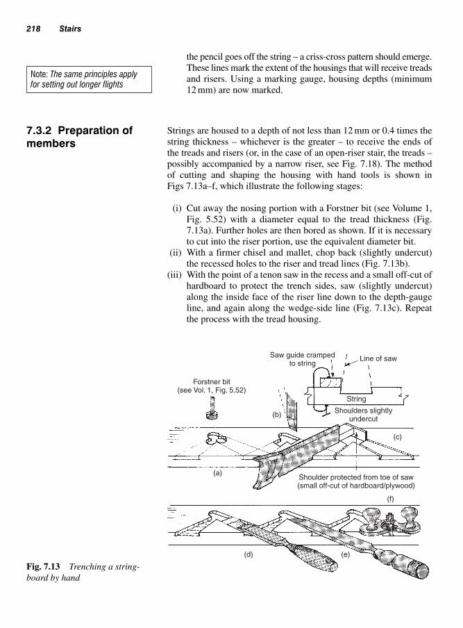
the pencil goes off the string – a criss-cross pattern should emerge.
These lines mark the extent of the housings that will receive treads
and risers. Using a marking gauge, housing depths (minimum
12 mm) are now marked.
Strings are housed to a depth of not less than 12 mm or 0.4 times the
string thickness – whichever is the greater – to receive the ends of
the treads and risers (or, in the case of an open-riser stair, the treads –
possibly accompanied by a narrow riser, see Fig. 7.18). The method
of cutting and shaping the housing with hand tools is shown in
Figs 7.13a–f, which illustrate the following stages:
(i) Cut away the nosing portion with a Forstner bit (see Volume 1,
Fig. 5.52) with a diameter equal to the tread thickness (Fig.
7.13a). Further holes are then bored as shown. If it is necessary
to cut into the riser portion, use the equivalent diameter bit.
(ii) With a firmer chisel and mallet, chop back (slightly undercut)
the recessed holes to the riser and tread lines (Fig. 7.13b).
(iii) With the point of a tenon saw in the recess and a small off-cut of
hardboard to protect the trench sides, saw (slightly undercut)
along the inside face of the riser line down to the depth-gauge
line, and again along the wedge-side line (Fig. 7.13c). Repeat
the process with the tread housing.
218 Stairs
Note: The same principles applyfor setting out longer flights
7.3.2 Preparation ofmembers
Saw guide crampedto string
Forstner bit(see Vol. 1, Fig. 5.52)
(b)
(a)
String
Line of saw
Shoulders slightlyundercut
(e)(d)
(f)
(c)
Shoulder protected from toe of saw(small off-cut of hardboard/plywood)
Fig. 7.13 Trenching a string-
board by hand

(iv) Remove most of the waste wood with a chisel and mallet (Fig.
7.13d) – avoid using the chisel up-turned, as it will tend to dig into
the trench bottom.
(v) Waste wood beyond the reach of a bench chisel can be pared
away with a long-bladed paring chisel (Fig. 7.13e).
(vi) Level the bottom of the trenches with a hand router (Fig. 7.13f – see
Volume 1, Fig. 5.37).
When a portable electric-powered router is to be used to cut the hous-
ings, a jig similar to the one shown in Fig. 7.14a would be suitable for
a fixed-base type; but the tread and riser inlet/outlet portions of the
jig can be omitted if a plunge-type router is to be used (Fig. 7.14b).
(A router template guide and its application are shown in Volume 1,
p. 190, Fig. 6.44.)
The string must be firmly held to the bench, just as the jig is to the string
(clamps and wedges may be employed), to enable the router to be safely
manoeuvred with both hands.
Figure 7.15 shows the use of a proprietary staircase jig clamped to
the stair string which is adjustable to suit the required rise and going
housings.
Figure 7.16 shows how an outer string is joined to the top and bottom
newels with mortise-and-tenon joints. The stub tenons should be not
less than 50 mm long and 12 mm thick. If the bottom step extends
beyond the newel face (see Figs 7.19 and 7.27), two haunches will be
used as shown.
Strings to open-riser stairs will require some provision to prevent
spreading. Several of the treads could be tenoned through the strings
and/or strings could be screwed to the housed treads. (Screw heads
Stair construction 219
String
String
(a) Inlet/outlet for non-plunge router
(b) Inlet/outlet not necessary with plunge routers
Note: Jigs must be securely held to workpiece (string) and workpiece to bench
Fig. 7.14 Jigs for trenching with a portable electric-powered router

Clamp
Note: Dust extraction not shown
Fig. 7.15 ‘Trend’ staircase jig
Handrail
Newel
A
B
A – Used with projecting bottom step
B – Used with non-projecting bottom step
= – Equal
Horizontal section X
Newel
String
Extendednewel
Pendant drop
X
Fig. 7.16 Outer string and
handrail to newels

should be domed or cupped – see Volume 1, page 252, Table 12.2 –
or sunk below the surface then covered with a wood pellet (see
Fig.7.17).) Steel brackets or tie rods with anchor plates may be other
alternatives – see Fig. 7.17.
Figure 7.18 shows different ways of preparing treads and risers.
Treads should be not less than 235 mm wide and their nosings should
project not less than 15 mm beyond the face of the risers. (Projection,
like tread width, must be uniform throughout the whole flight.) Riser
tops should be housed (e.g. plywood risers) or tongued to a depth of
not less than 5 mm, but never more than one quarter of the tread
thickness.
Riser bottoms may be tongued into the treads or grooved to receive
the tread. Open-riser stairs do not have a full riser. However, so that the
opening does not contravene the regulations (see Table 7.1), they may
use a narrow riser, either hanging down from the underside of a tread
(the most common method) or as an up-stand from the back of the
tread’s surface (this could serve as a dust trap, producing a ‘shadow’
line with polished stairs, Fig. 7.18).
Stair construction 221
7.3.3 Treads and risers
Wedge Strings
Tread
Pellet
Cup and cap
Screwed (screwheads capped, domed or
pelleted – See Vol. 1, p. 255)
Rod (tapped) and plate
Tie (MS)
Tie masked by‘drop’ riser
Housed and mortisedand tenoned
Dome
Fig. 7.17 Preventing string-
boards spreading
Note: As with the handrails stringshoulders may also be housed intothe newel posts to conceal anyshrinkage

Newels will be stop-mortised as shown in Figs 7.16 and 7.19 to a
depth of not less than 50 mm. The joints will eventually be tightened
by draw-boring and pinning as shown in Chapter 4, Fig. 4.45.
Housings which receive treads and risers should be not less than
12 mm deep.
Newel post tops are shaped according to style and ease of handling.
The pendant drop (Fig. 7.19) is similarly shaped – elaborate shapes
may provide inaccessible dust traps.
222 Stairs
Min. 5 mm
Plywood / MDF riser
Tongues and groovesnot less than 5 × 5 mm
Cove or similar bead
Screw line
All gaps must beless than 100 mm
Tread-and-riser stairs
Should be deep enoughto avoid toe trap
Alternative nosing
Mid-rail
Narrow ‘drop’ riser
Open-riser stairs
Dust trap‘Upstand’ riser
Fig. 7.18 Preparation of treads
and risers
7.3.4 Newels

The handrail above a wall string is fixed to the wall either directly (Fig.
7.20a) or via a steel bracket (Fig. 7.20b). A handrail forming part of
a balustrade may be fixed to the face of a newel post (Fig. 7.20c). In
most other cases, handrails are stub-mortised into the newel post –
the underside of some are grooved to receive the tops of balusters as
shown in Fig. 7.20d.
Stair construction 223
Mortised and housed to receive handrail
Draw-bored – (SeeChapter 4, Fig. 4.45)
Lower newel posts
Tread and riserhousing
min. 12 mmdeep
String
Tread – bottom step
NewelProtruding bottom step
Upper newel post
Pendantdrop
Fig. 7.19 Preparation of
newel posts
7.3.5 Handrails (Fig. 7.20)

Assembly may take place in one of two ways:
● laid flat (Fig. 7.21);● laid on edge (Fig. 7.23).
7.3.6.1 Laid flat
Figure 7.21 shows the various stages involved:
(i) Position strings face edge down on a framework of two runners
supported by cross-members (distance pieces). Use blocks to pre-
vent the clamps, which pass under the runners, from falling over.
The framework must not be twisted.
(ii) Position, glue, and cramp between strings enough treads (depend-
ing on the length of flight) to enable the stair to be checked for
square by measuring across the diagonals (see Fig. 7.23(c)), using
as measuring points the squaring marks transferred from the face
edge of the string at the setting-out or marking-off stage. Use side
runners to protect the strings and help distribute cramping pressure.
(iii) With two operatives opposite one another striking in unison, drive
glued wedges (ensuring treads are seated tight into the tread
housings) between the walls of the string housings and the
underside of the treads until tight.
(iv) Fix the remaining treads (except the bottom and top steps if newel
posts are to be used) in the same manner – extra cramps may be
required.
(v) Cut back protruding wedges to allow the risers to be slid into
position. Similarly wedge these risers, then screw them to the
back edge of the treads (Fig. 7.22).
(vi) Glue angle blocks (glue blocks) between the treads and risers –
two per tread for stairs up to 900 mm wide, three for stairs up to
224 Stairs
Mop-stick handrail
Newelpost
Plankhandrail
(c)
Note: Danger possible finger trap
Bracket
(b)
Caphandrails
(d)
Baluster
Built-up (laminated)handrail
(a)
Fig. 7.20 Examples of handrail sections and their fixing
7.3.6 Assembly of stair members

Stair construction 225
Bearers
Base runner
Block – cramp steady
Side runners – aid cramping
Softboardprotects stringsT bar cramp
top and bottom
Pneumatictable cramp
Riser wedge
B
Base framework
A Treadwedge
A-AA
Cramping square
C
C
Screwing risersto treads
C-C
Glue-blocking
D-D
Wedging (NB – clamps not shown)
BB-B
D
D
Line from faceused to square
framework
Fig. 7.21 Stair assembly – laid flat
990 mm wide, and four for stairs above 990 mm wide (distance
between blocks not to exceed 150 mm), as shown in Fig. 7.22.
For stairs with winders (see Fig. 7.25), glue blocks are spaced at
150 to 200 mm from the string and 150 to 225 mm thereafter.
An alternative method of cramping the stair would be by using a
proprietary pneumatic cramping table.
7.3.6.2 Laid on edge (Fig. 7.23)
This is generally a popular method of cramping.
(i) Pre-assemble treads and risers into steps with the aid of a jig/
cradle (Fig. 7.23a).

(ii) Lay one string flat on to an assembly bench (with a smooth
flat material positioned between the bench top and the string to
prevent the string faces being bruised) and position the assem-
bled steps into the string housings (Fig. 7.23b).
(iii) Seat the opposite string (ensuring that treads and risers are
squarely positioned in and against the front edge of the string
housings), then apply top pressure (Fig. 7.23c) via a purpose-made
226 Stairs
Min. 75 mm
Glue block(corner removed)
Min. length 2 × riser thicknessmin. penetration into tread 23 mm
Underside of stair
Stiffens joint (optional)
230 mm Min. ctrs thickness10 gauge (5 mm)
Fig. 7.22 Screws and glue
blocks
Cradle Plywood webStacking steps
(c)(b)
First placement
Plate
Second string – square – top pressure
Adjustablesteel frame
(d)
Strings
Plate
Bearer
Bench Bench
Use of metal cramping frames and folding wedges
(a)
Glue block nailedin position
Note: Stair is wedged while under pressure
Riser-to-tread assembly jig Under pressure
Foldingwedges
Fig. 7.23 Stair assembly –
laid on edge

cramping frame which may be fabricated from steel angle, lengths
of timber, and hardwood wedges (Fig. 7.23d). In this situation
the riser wedges are driven in first to ensure that the Pre-assembled
treads and risers are positioned tight into their housings.
(iv) Apply glue to wedges of top and bottom risers first, prior to
being driven.
(v) Check for square as previously described at section 7.3.6.1(ii).
(vi) Cut back protruding wedges to allow for tread wedges.
(vii) Continue as described at 7.3.6.1(vi).
Because of the narrowness or absence of risers, an open-riser stair must
be handled very carefully until temporary bracing has been fixed as
shown in Fig. 7.24, otherwise the joints between the treads and the string
may become strained, with the possibility of breaking the glue line.
Tapered treads or winders are used with a straight flight in most cases
(unless it is a spiral stair, see Approved Document K) to provide a
continuous turn without the use of landings and to give additional
headroom to a stair below as well as providing a pleasing effect to the
building.
However, this type of stair may prove to be more expensive to con-
struct and install, including in some cases problems when moving
furniture up and down the flights.
Building Regulations Approved Documents, A, D, and K will need
to be consulted before this type of stair is to be considered, which
does include the following:
(i) tapered treads at their narrowest end (radiating out from the
newel) must not be less than 50 mm, see Fig. 7.25f.
Stair construction 227
Broken joints (strain)
Open riser
Plywood of chipboard(stiffened to prevent
buckling)
BraceBearer
Stable stair
Unstable stair
Pressure
Note: Viewed from undersideFig. 7.24 Temporary bracing
for an open-riser stair
7.3.7 Straight flightswith winders (Fig. 7.25)
Note: If the bottom step is to proj-ect forward of the newel, it is builtseparately and left until the newelshave been fixed on site. Similarly,the top riser and nosing may beleft loose and fixed on site

(ii) a stair under 1 m wide (Fig. 7.25c) with tapered treads, when
used in conjunction with a straight flight, must all be equal
in depth (from nosing to nosing) and not less than the goings
on the straight flight when measured in the centre of the flight
(Fig. 7.25e).
(iii) a stair over 1 m wide (Fig 7.25d) with tapered treads, when used
in conjunction with a straight flight, must all be equal in depth
(from nosing to nosing), and not be less than the goings on the
straight flight when measured 270 mm in from both sides of the
strings (see Fig. 7.25g).
Figures 7.25 and 7.26 give two examples for this type of stair incorp-
orating tapered treads.
Figures 7.25a and 7.26a show a stair with a 90° turn (quarter turn)
using tapered treads and would be used in a situation where a straight
flight would be impractical because of limited space available.
Another example is shown in Figs 7.25b and 7.26b, which show a
180° turn (half turn) on the stair. This is ideally suited for a loft con-
version as the half turn takes account of the sloping roof and gives
sufficient headroom when in use.
228 Stairs
(a) (b)
(c)
Elevations
Up Up
Kite winder
Taperedtread
90° turn
180° turn
Kite winders
Quarter turnof winders
(tapered treads)
Half turnof winders
(tapered treads)
Planviews
270 270
270
270
(d)
Plan
Plan
(g)
Equal Equal
Equal
Equal
(e)
(f) Min. 50 mm
Fig. 7.25 Samples of stairs with winders (tapered treads)

Because of possible accidents on this stair type, consideration must
be given to Approved Document K in relation to design and fitting.
Furthermore, it is necessary to set out full size all the required true
shapes of treads, strings and setting out of the newel posts, to obtain
the construction details and required jigs.
Further details can be found in Carpentry and Joinery: Work Activities
by Brian Porter and Reg Rose (2002), section 11.10.
If a bottom step protrudes forward of a newel, it will be constructed
separately. Figure 7.27 shows how three of these step ends would
appear, together with details of how they may be made up, as follows:
(i) Splayed end (Fig.7.27a): Riser mitres may be tongued (with a ply-
wood tongue) or screwed together via a ledge. The riser is tongued
into and pocket-screwed on to the underside of the tread. The step
end is housed into and screwed to the newel.
(ii) Bull-nosed (quadrant) end (Fig. 7.27b): The riser is pre-formed
either by laminating several layers of wood veneer (plywood)
around a former or by bending and gluing thin plywood to a tim-
ber backing, with a built-up quadrant block. Fixing of the riser to
the tread and of the step to the newel are as above.
(iii) Half-round end (Fig. 7.27c): This has a similar construction to a
bull-nosed end, except that the step protrudes both forwards and
sideways.
In all cases, the underside of the tread will need grooving to receive the
riser tongue. This can be done with a portable electric-powered router,
as shown in Volume 1, 6.15.
Stair construction 229
Tapered tread
Tapered tread
Tapered tread
Taperedtreads
Tapered tread
Kite winderKite winder
Kitewinder
(a) (b)
Fig. 7.26 Examples of floor and well space in relation to tapered tread stairs
7.3.9 Shaped ends tobottom treads
7.3.8 Construction(tapered treads)

230 Stairs
Note: Once the stair assembly is completed and leaves the workshop it should be protected against any intake ofmoisture – particularly while in transit, be it to storage or site. Finished surfaces (especially polished hardwoods orsoftwoods) may need protection against scratches. Softwood rubbing strips or rolls of corrugated card or plastics,held in position with tape or bands, etc., could be used for this purpose.
Two brackets, glued and screwed to back of riser
Mitres withloose tongue
(glued)
Riser pocket – screwed to tread
Riser cut to veneer thicknessat this point – bent, glued, and
screwed to laminated block
Riser in the solid
Built-up (laminated block)
Thin plywood (1.5–2.0 mm)bent, glued, and pinned tosolid riser and corner block
Laminated veneers,or formed roundblock – as above
Bend
Part laminatedpart solid
(c) Half-round step – projected forwards and sideways of newel
Plan Plan
Elevation Elevation
PlanPlan
Elevation Elevation
Foldingwedges –
tighterveneer
Solid orlaminated
block
(a) Splayed-end step – projected forward of newel
Riser
Tongueand groove
PlanPlan
Elevation Elevation
Tread
Built-upformer
Bevelledto form hook
(b) Bull-nosed (quadrant) step – projected forward of newel
Fig. 7.27 Shaped ends to bottom steps

This type of design is only used in situations where there is insuffi-
cient space for a conventional stair, for example a loft conversion that
requires access to only one habitual room. See Building Regulations
Approved Document K.
Each tread has been specially shaped by removing part of the tread
(generally a quarter of the width) to form alternating handed treads
which must include non-slip surfaces.
The safety aspect of this stair relies on familiarity and regular use.
Additionally, a handrail must be included on both sides of the stair.
7.3.10.1 Construction (alternating treads)
The method of construction is similar to conventional stairs where
the treads are housed into the strings. However, wedges are generally
not included as these would be exposed and would not keep in with
the design of the surrounding area.
Treads may be secured by fixing through the strings into the end grain
of the treads to prevent spreading by the methods shown in Fig. 7.17.
The open risers must be constructed in such a way that a 100 mm diam-
eter sphere cannot pass through the gap below each tread, even when a
‘drop’ riser is included, Fig. 7.28 (see also, section 7.3.3 and Fig. 7.18).
Stair construction 231
Handrail must befitted to both sides
Maximumrise 220 mm
Timber/metal rodto conform to
Min. 100 mm gap
Min. going 220 mm
Min. 16 mmoverhang
Tread reducedto 3/4 width
Gap must be small enoughnot to permit the passage
of a 100 mm diameter sphere 100Alternative method
with ‘drop’ riser
Fig. 7.28 Alternating treads
7.3.10 Alternatingtreads (Fig. 7.28)

Balustrades may be described as having either:
(a) an open vertical infilling of balusters;
(b) an open sloping infilling of knee-rails, or
(c) a closed (solid or panelled) infill.
Open vertical balusters (Fig. 7.29a): Square (32 mm � 32 mm), rec-
tangular (32 mm � 61 mm), or spindle (45 mm � 45 mm) sections
may be used as balusters. They are mortised or housed with or without
‘spacers’ into the handrail and the string or string capping.
232 Stairs
7.4 Balustrades
Infill sections(balusters)
Square SpindleRectangular
Spacer
Baluster
StringOpenverticalinfilling
(a)
(c)
(b) Open sloping knee-rails(see Fig. 7.8(c))
String
String
String
Capping
Inclined sections
Muntin
Panel
String
Stubtenon
Panelled
Plywood panel
Bottom railString capping
String
Inclined section
Panel
Fig. 7.29 Types of balustrades
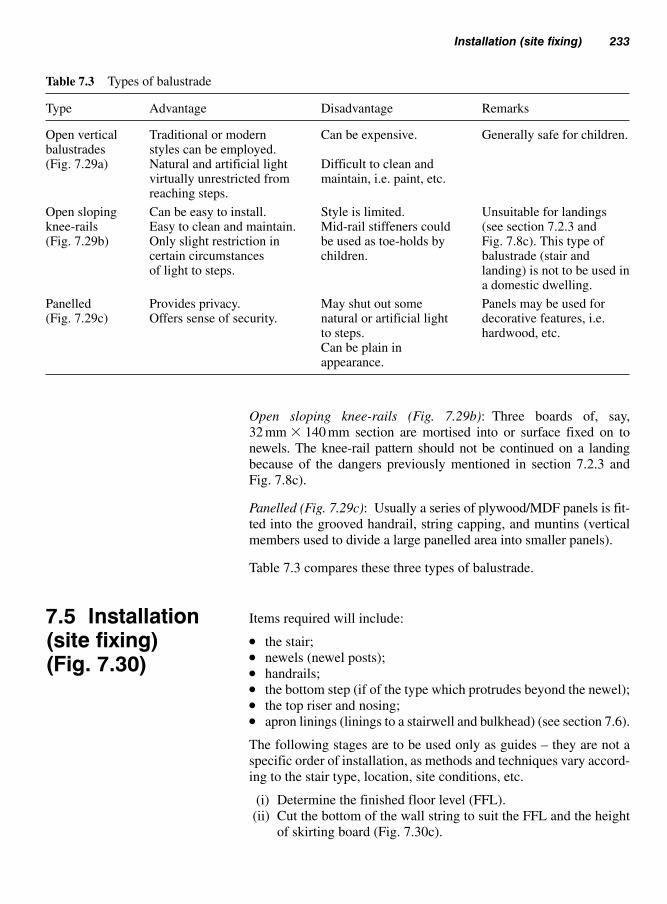
Open sloping knee-rails (Fig. 7.29b): Three boards of, say,
32 mm � 140 mm section are mortised into or surface fixed on to
newels. The knee-rail pattern should not be continued on a landing
because of the dangers previously mentioned in section 7.2.3 and
Fig. 7.8c).
Panelled (Fig. 7.29c): Usually a series of plywood/MDF panels is fit-
ted into the grooved handrail, string capping, and muntins (vertical
members used to divide a large panelled area into smaller panels).
Table 7.3 compares these three types of balustrade.
Items required will include:
● the stair;● newels (newel posts);● handrails;● the bottom step (if of the type which protrudes beyond the newel);● the top riser and nosing;● apron linings (linings to a stairwell and bulkhead) (see section 7.6).
The following stages are to be used only as guides – they are not a
specific order of installation, as methods and techniques vary accord-
ing to the stair type, location, site conditions, etc.
(i) Determine the finished floor level (FFL).
(ii) Cut the bottom of the wall string to suit the FFL and the height
of skirting board (Fig. 7.30c).
Installation (site fixing) 233
7.5 Installation(site fixing) (Fig. 7.30)
Table 7.3 Types of balustrade
Type Advantage Disadvantage Remarks
Open vertical Traditional or modern Can be expensive. Generally safe for children.balustrades styles can be employed.(Fig. 7.29a) Natural and artificial light Difficult to clean and
virtually unrestricted from maintain, i.e. paint, etc.reaching steps.
Open sloping Can be easy to install. Style is limited. Unsuitable for landings knee-rails Easy to clean and maintain. Mid-rail stiffeners could (see section 7.2.3 and (Fig. 7.29b) Only slight restriction in be used as toe-holds by Fig. 7.8c). This type of
certain circumstances children. balustrade (stair and of light to steps. landing) is not to be used in
a domestic dwelling.
Panelled Provides privacy. May shut out some Panels may be used for (Fig. 7.29c) Offers sense of security. natural or artificial light decorative features, i.e.
to steps. hardwood, etc.Can be plain in appearance.
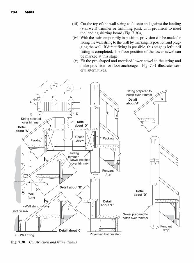
(iii) Cut the top of the wall string to fit onto and against the landing
(stairwell) trimmer or trimming joist, with provision to meet
the landing skirting board (Fig. 7.30a).
(iv) With the stair temporarily in position, provision can be made for
fixing the wall string to the wall by marking its position and plug-
ging the wall. If direct fixing is possible, this stage is left until
fitting is completed. The floor position of the lower newel can
be marked at this stage.
(v) Fit the pre-shaped and mortised lower newel to the string and
make provision for floor anchorage – Fig. 7.31 illustrates sev-
eral alternatives.
234 Stairs
AB
DE
C
String notchedover trimmer
Detailabout ‘A’
Detailabout ‘D’
Packing
Landingtrimmer
A
A
X
X
X
Newel notchedover trimmer
Detail about ‘B’
Detail about ‘C’
Detailabout ‘E’
Detailabout ‘D’
Detailabout ‘A’
Wallfixing
X = Wall fixing
Wall string
Section A-A
Projecting bottom step
Newel prepared tonotch over trimmer
Pendantdrop
Pendantdrop
Coachscrew
Packing
String prepared tonotch over trimmer
Fig. 7.30 Construction and fixing details

Installation (site fixing) 235
Steel tube or bar sunkinto concrete slab
FFL
FFL
Screed
Newel set into screed
Concrete floor
Decking
Nogging
Joist hanger
Joists
Nogging
Plan views (decking not shown)
Joist ornogging
Bolt
Cleat
Skew-nailedNewel
Fig. 7.31 Bottom newel – post
anchorage
(vi) Attach the lower newel to the string using draw-pins (pointed
hardwood dowel, see Figs 7.16 and 7.19).
(vii) Fit and fix the pre-made bottom step to the wall string (glue and
wedge, Fig. 7.30c), the riser (glue and screw the riser to the
tread or the tread to the riser), and the newel (screw the step
riser to the newel, Fig. 7.30e).
(viii) Notch the top newel over the trimmer to form a location joint
(Fig. 7.30d). If the stairwell is not square with the wall, small
allowances may be made at this stage.
(ix) Assemble the top newel to the string and handrail and (if used)
the knee-rails to both newels. Joints are glued and drawn
together as necessary, draw-board. If balusters are tenoned

to both the handrail and the string, they too must be included
at this stage.
(x) Fit the top riser and the landing nosing and fix together (glue
and pocket-screw, Fig. 7.27a). Glue and screw the assembly to
the string, newel housing, and the tread below. Alternatively, the
landing nosing and top riser may be fitted after the stair has been
fitted in place. The top landing nosing is positioned in place
with the top riser pushed up from underneath and ‘packed’ off
the face of the trimmer (Fig. 7.30a). Once fitted, it is then secured
to the top tread.
(xi) Locate the stair into its final position. Check for wall and floor
alignment and that the newels are plumb.
(xii) Securely fix the lower newel (the method will depend on the
type of floor construction, Fig. 7.31). Fix the top newel from
trimmer to newel using a coach screw (see Fig. 7.30(d)) and the
landing nosing to the trimmer. Nail or screw (depending on the
base material) the wall string to the wall at under tread locations
(Fig. 7.30b) – use wood packings at fixing points between the
wall and the string if after alignment it is found that there are any
gaps; otherwise the stair could be either distorted or damaged.
(xiii) Cut and fix string balustrades with equal gaps, as shown in
section 7.8.1.
Landing balustrade assemblies form an attachment with their handrail
and floor margin strip (Fig. 7.33a). They may be fixed with the stair or
at a later stage – in either case the stairwell opening must not be left
without guard rails.
The exposed edges of the stairwell can be lined with either solid timber
or plywood (Fig. 7.33a). The lining (apron) is packed off the trimming
to provide edge support to a margin strip that edges the landing decking
and may provide a fixing for balusters. The under edge, which could act
as an edge for the plasterer, is covered by a wood trim.
In situations where the room above a stair extends forward of the stair-
well, a bulkhead similar to that shown in Fig. 7.33b may be formed.
236 Stairs
Note: Before the stair is tried(reared up) in its intended posi-tion, a securely anchored groundstay (kicker) will be required at thefoot of the stair as a precautionagainst the stair sliding, as shownin Fig. 7.32
7.6 Apron liningsand bulkheads
Slide
Against wall
Danger
Fig. 7.32 Providing a tempor-
ary stair anchor

Once installation is complete, treads (particularly their nosings) can
in some cases be protected from the traffic of operative’s footwear by
tacking thin strips of wood, plywood, or hardboard (rough side up) to
the surfaces.
Newels can easily be damaged by the movement of building materials
(lengths of timber, pipes, etc.). This risk can be reduced by wrapping
them in card or plastics and/or tying narrow strips of hardboard or
plywood, etc. around them with tape or bands.
Handrails may need similar protection.
Before any templates (pitch board, etc.) or jigs (a cramp-on guide for
repetitive work, i.e. cutting housings, Figs 7.10 and 7.14) can be made,
the rise and going for each step must be calculated from the information
obtained from the site visit (see section 7.2.1).
A stair may be designed to be constructed to use the minimal amount
of materials and space, however at the same time it must conform to
current Building Regulations (Approved Document K).
Stair calculations 237
7.7 Protection
7.8 Staircalculations
Room wall
Bulkhead
Stair
Headro
om
Baluster
Margin strip(nosing) Decking
Joists
Solid orplywood/
MDF lining
Trim Trimmer
(a) Apron lining
Stair pitch
(b)
Bearer
Plasterboardsoffit
Void
Shelf
Possible cupboardspace Stud
Trimmer
PartitionPitc
h line(b)
Fig. 7.33 Stairwell lining and
bulkhead construction

A situation may arise where the subdivisions (number of rises) of the
total rise and going may not be exactly equal to the total rise or going
of the original measurements from site, in which case they are adjusted
accordingly.
The final measurement may be 1 to 5 mm over or under – this differ-
ence in measurement can be, in some cases, lost in the fitting and the
cleaning-up process. However, amounts 5 mm or over may prove to
be more difficult.
Example calculation for a domestic (private) dwelling
Let’s assume a total rise of 2.52 m from FFL to FFL (finished floor
level) and a total going from the face of the first riser to the face of the
last riser of 3.25 m. These are the measurements obtained from site.
Using a calculator (similar to Fig. 7.35) and the maximum step rise
of 220 mm (as shown in Tables 7.1 and 7.4), divide this figure into the
total rise of 2520 mm; this will give you 11.454. We can round this
up to 12.
We can now divide the rise (2520 mm) by 12 to give 210 mm, which
is below the maximum of 220 mm. Because the stair in question now
has 12 risers, it will require 11 goings (always one less than the num-
ber of risers).
Therefore, to summarize, a single riser height can be calculated as
follows:
2520 � 220 � 11.454 (round up to 12 risers)
2520 � 12 � 210 mm (for each riser)
So this particular stair has 12 risers at 210 mm with 11 goings (whose
size is yet to be determined). The maximum angle for a private stair
is 42° (see Table 7.1). To be on the safe side an angle of 41.9° would
be preferable to use.
At this point you will require a scientific calculator – alternatively
refer to section 7.3.1, Setting-out.
The tangent of an angle (Tan) (Fig. 7.34)
This is the result of the ratio of the opposite and adjacent sides in a
right-angled triangle. If the angle and the length of one of the sides are
known it is possible, by the use of trigonometry, to obtain the unknown
length of the other side.
238 Stairs
Note: In this example, all measure-ments will be expressed in millimetres.

Alternatively, if the length of the opposite and adjacent sides are known,
the angle can be determined by rearranging (transposing) the formula
(Fig. 7.34).
To find the going (adjacent), the formula for the tangent (Tan) of an
angle can be used but will need transposing (rearranging) a number
of times until the required formula to find the adjacent is obtained.
As the rise and angle is known, the formula of Tan, which is the result
of the length of the opposite side of the known angle divided by the
length of the adjacent side of the known angle, can be used.
This is written first as:
First, as the adjacent is the unknown factor, we arrange the formula
so that both sides are required to be multiplied by the adjacent.
Therefore:
Because the right-hand side has two adjacents, they can both be can-
celled out.
Therefore:
Which leaves us with:
The left-hand side now contains Tan, which we need to remove as we
only want the adjacent.
Tan Adjacent Opposite� �
Tan AdjacentOpposite
AdjacentAdjacent� � �
Tan AdjacentOpposite
AdjacentAdjacent� � �
TanOpposite
Adjacent�
Stair calculations 239
(Adjacent)
Tan of 41.9° �Opposite
Adjacent
41.9°
(Opposite)
Ris
e =
210 m
m
Fig. 7.34 The tangent of
an angle
Note: Remember that any series ofadjustments must be kept in bal-ance, i.e. both sides!

We can do this by dividing both sides by Tan.
Tan is placed under the formula (because we are dividing) on both sides
in order to keep in balance.
Therefore:
Now as Tan appears twice on the left-hand side, they cancel each
other out.
Therefore:
So finally, we are left with our required formula for determining the
adjacent.
This now reads:
Therefore:
Using a scientific calculator (Fig. 7.35), the Tan of 41.9° is required.
This is carried out by typing 41.9 and then pressing the Tan button
(Fig. 7.35) � 0.897248684.
Therefore to find the going, the rise of 210 is divided by
0.897248684 � 234.048 mm, or 235 mm (rounded up)
To summarize,
Going210
.897248684235 mm� �
Adjacent (going)210
Tan 41.9º�
Adjacent (going)Opposite
Tan�
Tan Adjacent
Tan
Opposite
Tan
��
Tan Adjacent
Tan
Opposite
Tan
��
240 Stairs
41.9
2nd functionbutton
Tan button Tan button
2nd functionbutton
2nd F
2nd F DEG 2nd F DEG
ONOFFlogIn
0 =++/-
1 M+�32
4 RMX65
EXP )(X2%
� tancossin
7 x m�98
.897248684
2nd F ONOFFlogIn
0 =++/-
1 M+�32
4 RMX65
EXP )(X2%
� tancossin
7 x m�98
Fig. 7.35 Using a calculator to obtain the TAN of 41.9º
Note: Ensure that the calculator isset to degrees (DEG)

Finally, with this calculation, the stair has:
12 risers at 210 mm, with 11 goings at 235 mm, with a pitch of 41.9°
However, we must now check the aggregate (the amount or sum of
the ratio 2 � R � G must be between 550 and 700).
Their aggregate, according to the rule would therefore be:
2 � 210 � 235 � 655 mm
As 655 mm is not less than 550 mm nor more than 700 mm, this will
be acceptable provided that the angle formed by the going and the
pitch line (hypotenuse) is between the acceptable limits of 32° and
42° – which it is.
Finally, we can carry out the following checks:
To check the risers against the total rise measurement,
210 � 12 � 2520 � original total rise.
To check the goings against the total going measurement,
235 � 11 � 2585 � below original total going of 3250,which is satisfactory.
The angle 41.9° used in this calculation is under the maximum accept-
able limit of 42° for combinations of rise and going within the fol-
lowing ranges shown at (a) in Table 7.4.
Example stair calculation under the category forinstitutional and assembly
For a stair that comes under Institutional and Assembly (where
people gather), for example a hospital or hotel, the calculations are
similar to a private stair, but by using the maximum riser height and
minimum going (Table 7.5) the angle achieved will always be just
over 32° as opposed to a private stair (Table 7.4b), where there is a
possibility of exceeding the maximum angle of 42°.
It should not, however, be less than 30° as this could prove to be too
tiring when walking up the stair; for example, by using the minimum
rise of 135 and maximum going of 340 it will give an angle of 21°
which is far too low.
Assuming a total rise of 2.555 m with a total going of 4.5 m
Stair calculations 241
Table 7.4 Combinations of rise and going for private stair
Rise (mm) With Going (mm)
(a) 155 to 220 245 to 260or
(b) 165 to 200 223 to 300

Therefore:
2555 divided by the maximum rise of 180 � 14.194
� 15 (rounded up)
2555 divided by 15 � 170.3333 (15 risers at 170.3333 mm)
0.3333 of a millimetre is so small that it would be difficult to include
in the measurements so the rise could be rounded up to 171.
To check to see how it compares to the original total rise of 2555,
171 � 15 � 2565
This now means we are oversize by 10 mm, which would be difficult
to lose during fitting.
Therefore:
Let’s try 170 mm, but by checking the measurements again,
170 � 15 � 2550
We are now under by 5 mm.
Another way would be to use
170.5 � 15 � 2557.5
That now means we are over by only 2.5 mm, even better!
Again, this may be adjusted on site after fixing.
To summarize:
2555 � 180 (max rise) � 14.194 (round up to 15)
2555 � 15 � 170.3333 (round up to 171)
15 � 171 � 2560 (oversize by 10 mm)
Try:
15 � 170 � 2550 (undersize by 5 mm, but may be lost when fixing on site)
Try adding 0.5 mm to 170 mm
15 � 170.5 � 2557.5
242 Stairs
Table 7.5 Combinations of rise and going for Institutional& Assembly stair
Rise (mm) with Going (mm)
135 to 180 280 to 340

We are now oversize by 2.5 mm, which is easily lost when fixing on
site. However, 0.5 mm is difficult to work with so in this example we
will use 170 mm for each riser. This will mean we are under by 5 mm
on the total rise (2.555 m). But as stated previously, this may be
adjusted when fitting the stair on site.
To check the angle the required minimum going of 280 mm (Table 7.5)
is divided into 170 (rise) using the scientific calculator (Fig. 7.37)
and the formula for Tan (Fig. 7.36).
170 divided by 280 � 0.607142857. Now by pressing the 2nd func-
tion on the calculator, then the Tan button (Fig. 7.37), the angle
obtained is just over 31°.
To summarize, the stair has 15 risers at 170 mm with 14 goings at
280 mm. According to the rule of twice the rise plus the going
(2 � R � G) should be between 550 and 700, their aggregate would be:
2 � 170 � 280 � 620 mm.
As 620 mm is not less than 550 mm nor more than 700 mm, this will
be acceptable provided that the angle formed by the going and the
pitch line (hypotenuse) is between the acceptable limits of around
30° to 32°, which it is.
Stair calculations 243
Going � 280 mm
Tan �Opposite
Adjacent
Tan°
Ris
e �
170 m
m
Fig. 7.36 Using Tan to find
the angle
.607142857
2nd functionbutton
2nd functionbutton
Tan button Tan button2nd F
2nd F DEG 2nd F DEG
ONOFFlogIn
0 =++/-
1 M+�32
4 RMX65
EXP )(X2%
� tancossin
7 x m�98
31.26373169
2nd F ONOFFlogIn
0 =++/-
1 M+�32
4 RMX65
EXP )(X2%
� tancossin
7 x m�98
Fig. 7.37 Calculating the angle

Once the stair has been fitted and the handrail is in place, the balus-
ters are cut and fixed into the underside of the handrail (Fig. 7.20 and
7.29), and into the string or string capping (or in the case of landings,
the landing capping).
In this example we have 12 goings at 258 mm with 95 � 95 mm newel
posts and we will use 32 � 32 mm spindles. The horizontal gap
measured between each of the vertical balusters is obtained first by
adding together the total step goings measured between the newels of
the stair (Fig. 7.38).
As the top and bottom riser faces are generally central on the newel
post, a deduction of 2 �1⁄2 the thickness of the newel post is taken off
the total goings.
For example, there are 12 goings at 258 � 3096 � 2 �1⁄2 the thick-
ness of newel, i.e. 95. This will leave 3001 mm as shown in Fig. 7.38
(spindle run).
As the Building Regulations stipulate that a 100 mm sphere cannot
pass through any openings, this needs to be included when calculat-
ing the final gap size.
To obtain the number of balusters, the formula used would be:
Example (Fig. 7.38)
The diagram in Fig. 7.38 shows two examples where spindles are to
be fitted and spaced equally, either on the stair or along the landing.
In both cases, the horizontal run must be obtained first.
Therefore:
Spindle run � 3001 mm, spindle width � 32 mm.
The figure is now rounded up to give 23 spindles with 24 gaps (always
one more gap than the number of spindles).
To obtain the exact spacing between each baluster, the spindle widths
are multiplied by the number of spindles required. This figure is then
deducted from the spindle run.
3001
32 10022.7348
�� �
3001
132
Spindle run
Spindle width 100�
244 Stairs
7.8.1 Calculating thenumber of balustradesand the spaces in-between (Fig. 7.38)

Finally, the result is divided by the number of gaps.
Therefore:
Example
Using the information above:
The result is 23 spindles with 24 gaps spaced at 94.3 mm.
Finally, to recap, stair calculations are not always straightforward
and do require figures to be adjusted to suit the situation. A copy of
the current Building Regulations for consultation is always required
when undergoing this task.
A stair usually includes a capping piece (Fig. 7.29), which is wider
than the thickness of the string by around 12 mm, and grooved (usu-
ally 6 to 8 mm deep) both sides along its length. The groove under-
neath the capping is designed to fit over the top edge of the string,
and once cut is secured in place, whereas the groove along the top
edge (whose width is the same thickness as the balusters) will allow
the spacing and fixing of the balustrade. Usually a chamfer or pencil
round is included along the top edges of the capping.
Once the balusters are fixed in place, it is usual practice to fill in the
exposed groove between each of the balusters with a spacer.
For this exercise we are using the horizontal space between the balus-
ters obtained in section 7.8.1 above. To obtain the true length of the
3001 (32 23) 3001� ��
��
24
736
2494 375.
Spindle run (spindle widths no. of spindles� � ))
no. of gaps
Stair calculations 245
7.8.2 Calculatingspacer length betweenbalusters (spindles)using a stair of 41.9°
Landing
3001 mm (Spindle run)
3001 mm (Spindle run)
95 × 95Newel posts
Fig. 7.38 Calculating spindle
gaps

spacers, and assuming the gaps are equal, calculations using Tan and
Pythagoras theorem are used together with the horizontal measure-
ment between each baluster (see section 7.8.1) and the angle of the
stair (Fig. 7.39).
Before we can obtain the length of X (the true length of the spacer)
the length of the opposite side needs to be found first.
To find the length of the opposite side, the formula for the tangent
(Tan) of an angle can be used, but will need transposing (rearran-
ging) until the required formula to find the opposite is obtained.
As the adjacent side and angle is known, the formula of Tan, which is
the result of the length of the opposite side of the known angle divided
by the length of the adjacent side of the known angle, can be used.
This is written first as:
First, as the opposite is the unknown factor, we arrange the formula
so that both sides are required to be multiplied by the adjacent.
This is written here as:
Because the right-hand side has two adjacents, they can both be can-
celled out.
Tan AdjacentOpposite
AdjacentAdjacent� � �
TanOpposite
Adjacent�
246 Stairs
Balusters
94.3Adjacent
94.3Adjacent
41.9° 41.9°
Opposite
Opposite
Stair cappingString
Length of spacer
X
Fig. 7.39 Calculating spacer
length between balusters
Note: Remember any series ofadjustments, must be kept in bal-ance, i.e. both sides!

Stair calculations 247
Therefore:
This leaves us with:
We now have the required formula to obtain the length of the
opposite side
Therefore:
Tan 41.9° � 94.3 � Opposite side
Using the calculator we first find the Tan of 41.9° as before in Fig.
7.35, which is 0.897248684, by inserting 41.9 and pressing the Tan
button.
Now we multiply 0.897248684 by 94.3 which gives us 84.6 – the
length of the opposite side.
Using Pythagoras’ theorem below, we can obtain the length of X – the
length of the spacer (Fig. 7.39).
‘The square on the hypotenuse of a right-angled triangle (X) is
equal to the sum of the squares of the opposite two sides.’
The term ‘square’ refers to the length of each of the sides multiplied
by themselves.
For example 94.3 � 94.3 � 84.6 � 84.6.
The calculator can be used for this operation as it contains a ‘square’
button (Fig. 7.40).
First type in 94.3 and then press the X2 button to obtain 8892.49.
Tan Adjacent Opposite� �
Tan AdjacentOpposite
AdjacentAdjacent� � �
94.3
2nd F
DEG
ONOFFlogIn
0 =+.+/-
1 M+32
4 RMX65
EXP )(X2%
tancossin
7 x m98
8892.49
Squarebutton
÷
�
�
Tan button2nd F
DEG
ONOFFlogIn
0 =+.+/-
1 M+32
4 RMX65
EXP )(X2%
tancossin
7 x m98
Squarebutton
Square rootbutton
Recall memorybutton
Memory in button
Tan button
Square rootbutton
Recall memorybutton
Memory in button
÷
�
�
Fig. 7.40 Finding the square of a given figure

This figure is stored in the calculator by pressing the M� button.
Repeat the same process for 84.6.
Both results are now stored.
To recall the results, the recall memory (RM) button is pressed to
give 16049.65 (Fig. 7.41).
We now need to find what number multiplied by itself will give us
16049.65.
This is known as the ‘square root’ of a number (Fig. 7.41).
The square root button is finally pressed to give us the true length of the
spacer, which is 126.6 mm.
248 Stairs
16049.65 126.6
Tan button2nd F
DEG
ONOFFlogIn
0 =+.+/-
1 M+32
4 RMX65
EXP )(X2%
tancossin
7 x m98
Squarebutton
Square rootbutton
Recall memorybutton
Memory in button
÷
�
�
Tan button2nd F
DEG
ONOFFlogIn
0 =+.+/-
1 M+32
4 RMX65
EXP )(X2%
tancossin
7 x m98
Squarebutton
Square rootbutton
Recall memorybutton
Memory in button
÷
�
�
Fig. 7.41 Obtaining the true length of the spacer
References
Building Regulations, Approved Document K, Protection from falling,
collision and impact, section K1: 2000.
Building Regulations, Approved Document A, Structure: 2000.
Building Regulations, Approved Document D, Toxic substances:
2000.
BS 5395: Part 1: 2000, Stairs, ladders and walkways. Code of practice
for the design, construction and maintenance of straight stairs and
winders.
BS 7956: 2000, Specifications for primers for woodwork.
BS 4071:1996 (amended 1992), Specification of polyvinyl acetate
(pva) emulsion for wood.
BS EN 923, 2005 Adhesives. Terms and definitions.
BS EN 12436: 2002, Adhesives for load-bearing timber structures.
Casein adhesives. Classification and performance requirements.
BS EN 1186–2, 1988, Timber for, and workmanship in joinery.
Specification for workmanship.
BS EN ISO 4618–3:2000, Paints and varnishes. Terms and definitions
for coating materials. Surface preparation and methods of application.
HSE (Health & Safety Executive) Manual handling leaflets.

With the exception of the ‘Delft’ shelf, which is sometimes called a
‘Plate’ shelf, examples as to where we might find wood trims and fin-
ishes are shown in Fig. 8.1. Table 8.1 can be used to identify and locate
the most common of these wall trims and finishes so as to ascertain
whether they have a functional or decorative role, or possibly both.
Take note that architraves and skirting boards have several functions;
these include:
(a) Concealing gaps which are likely to occur as a result of moisture
or thermal movement from abutting dissimilar materials;
Wood wall trimsand finishes
8
Ceiling accesshatch
ArchitravePlaster cornice
Ceiling access hatchArchitrave
Framedfilling panel
Spandrelpanel in fill
Plinth block orarchitrave block
Drop or falsecornice
Frieze/picturerail
Frieze
Filling area
Dado/chair/waist rail
Dado area
Skirting board(plinth)
Servinghatch
Plaster cornice
Fig. 8.1 Examples as to where internal trims and finishes may be found

(b) Protecting plasterwork from the occasional knock at floor level
by floor cleaning machines;
(c) Providing a decorative finish, and in some cases a decorative
feature.
Dado rails on the other hand can:
(a) Physically protect plasterwork at or about waist height when
moving furniture or chairs up against a wall;
(b) Serve solely as a decorative feature.
Where trims are used, or serve as a means to protect a wall’s surface
(plasterwork, see Fig. 8.2), wood or wood composites (section 8.1.1)
250 Wood wall trims and finishes
Potential damage due tounprotected plasterwork
Skirting board acting as abuffer to protect plasterwork
Vacuumcleaner
Vacuumcleaner
Potential damage to plasterwork
Trolley or furniturepushed against a wall
Chair being rocked orpushed against a wall
Fig. 8.2 Wall trims used to pro-
tect plasterwork

are the ideal medium for this purpose because they are much more
resilient to knocks than plasterwork.
Decorative properties: with the exception of a specific ‘chair rail’
(Fig. 8.2), all the other items listed in Table 8.1 will be shaped as a
moulding to be in keeping with the design and style of the room.
Unlike shaped sections used for doors and windows (section 4.5.3,
Fig. 4.15 and section 3.2.1, Fig. 3.6) the shaped edge or edges of
moulded trims do not always reflect their end use. Some do, how-
ever, have recognizable profiles, which carry a common name recov-
ered from a bygone age of the classical periods. It is these classical
lines (see Volume 1, section 1.9.4) that we tend to copy when repro-
ducing the various shapes we call mouldings.
Figure 8.3 shows how classical shapes based on the Roman and
Grecian styles can be reproduced using simple geometrical means.
Roman styles are based on the arcs of a circle (see Volume 2, section
4.1), whereas Grecian styles may be based on the softer curves of the
ellipse, parabola and hyperbola formed as a result of conic sections.
Figure 8.4 shows how conic section are derived by taking vertical
and sloping sections though a cone – hence the term ‘conic’ sections.
Mouldings (shaped sections) 251
Table 8.1 Wall trims and finishes (Mouldings) in relation to their use
Component Functional Decorative Location
Architrave Yes (P) Yes Wall to door/hatch lining Ceiling to hatch lining
Skirting board Yes (P) Yes Wall to floorPlinth blocks Yes (P) Yes Joints between architrave (Fig. 8.17) and skirting boardCorner block Yes (P) Yes Corner joints between (Fig. 8.13) architrave legs & headDado (chair or Yes/No Yes (P) Wall trim (830–900 mm) waist) rail above floor level(Fig. 8.2)Picture (frieze) Yes/No Yes (P) Wall trim (400–500) rail (Figs 8.1, below ceiling level8.5 and 8.31)Delft (plate) shelf Yes (P) Yes Wall trim (400–500) (Fig. 8.35) below ceiling levelCornice (drop or Yes (P) Yes Wall trim – can be usedfalse) (Fig. 8.37) to house concealed
lighting unitsInfill panel frame No Yes (P) Wall trim – mid-way (Fig. 8.39) between picture rail &
dado rail
‘P’ � primary use.
8.1 Mouldings(shapedsections)

Romanbased on arcs
Grecianbased on ellipse or parabolic curve
Cove (cavetto)
Ellipticalmoulding
Ovolo
HyperbolicHyperbolic Parabolic
Quadrant(bullnose)
Scotia
Inclinedellipticalmoulding
Cyma-recta(ogee)
Parabolicmoulding
Cyma-reversa(reverse ogee)
Parabolicmoulding
1 2 3 40
1
2
3
4
4
3
2
1
04 3 2 1
0
1
2
3
40 1 2 3
0123
1
2
3
0 1 2 3
12
3
0
0
1
1 2
2
3
35
5
6
6 7
7
0
01
1
2
2 3
34
5
5 6
6
7
7
8
8
8
8
Fig. 8.3 Drawings geometrically formed shapes suitable for mouldings

Commercially produced shaped sections (profiles) for architraves
and skirting boards are generally limited to a small number or design
profiles; similarly repeated sections are however available in various
sizes. Examples of these are shown in Fig. 8.5, together with profiles
for dodo and picture rails and various panel mouldings.
If a painted finish is required it can be most cost effective to use clear
grades of softwood, preferably Redwood (dead and large live knots
must be avoided on the moulded portion). Medium density fibreboard
(MDF) (Vol. 1, section 4.6.6 change) mouldings are a more modern
and popular alternative, providing an unblemished surface usually
pre-painted as part of the manufacturing process. MDF profiles are
also available covered in a variety of different films, to simulate dec-
orative hardwoods. The use of hardwood moulded profiles is usually
reserved for small decorative features and finishes.
Propriety, or commercially produced shaped sections used as mould-
ings are produced either by:
(a) Moulding machine;
(b) Spindle moulder (vertical spindle or shaping machine);
Mouldings (shaped sections) 253
Perspective view ofcone sections A-C
Plan viewof sections
Hyperbolasection C-C
Ellipsesection A-A
Parabolasection B-B
B
BC
C
A
A
C
A
B
Fig. 8.4 Shapes derived from
sections of a cone (conic sections)
used to form Grecian mouldings
8.1.1 Materials usedfor mouldings
8.1.2 Forming theshaped profile

(c) Embossing (pressing);
(d) Machine carving (using computer-aided-design ‘CAD’).
Purpose-made mouldings are produced either by:
(a) Spindle moulding (this machine is outside the scope of this series
of books. Special training and certification is required before oper-
ating a spindle moulding machine);
(b) Portable powered hand router with shaped cutters (Volume 1,
section 6.15);
(c) Hand tools (including moulding planes) (Fig 8.7);
(d) Combination and multi-planes (universal plane) (Fig 8.8).
254 Wood wall trims and finishes
Skirting
25 × 225 mm25 × 175 mm25 × 150 mm25 × 125 mm19 × 150 mm
25 × 175 mm25 × 150 mm
19 × 150 mm19 × 100 mm 19 × 75 mm
19 × 150 mm19 × 75 mm 16 × 75 mm
19 × 150 mm19 × 75 mm 16 × 75 mm
25 × 150 mm25 × 100 mm
19 × 150 mm19 × 75 mm16 × 100 mm
19 × 100 mm16 × 100 mm16 × 75 mm
19 × 100 mm
19 × 100 mm
25 × 75 mm
25 × 63 mm 25 × 38 mm 19 × 50 mm 25 × 50 mm
19 × 50 mm
19 × 75 mm19 × 63 mm19 × 50 mm16 × 50 mm
19 × 75 mm19 × 50 mm16 × 75 mm16 × 50 mm
16 × 75 mm16 × 63 mm16 × 50 mm
19 × 75 mm19 × 63 mm19 × 50 mm
25 × 75 mm25 × 63 mm
19 × 75 mm19 × 63 mm19 × 50 mm
19 × 75 mm19 × 63 mm19 × 50 mm
25 × 75 mm25 × 63 mm25 × 50 mm
25 × 75 mm25 × 63 mm
Torus/ogee (reversible) skirting
Architrave
19 × 50 mm 19 × 38 mm 12 × 38 mm 12 × 25 mm
Astragal
19 × 50 mm 16 × 38 mm 12 × 38 mm 12 × 32 mm 12 × 25 mm
Ogee panel mould
Ogee arcitrave
Ovolo arcitrave
19 × 50 mm 16 × 50 mm 16 × 38 mm 16 × 25 mm
12 × 25 mm 12 × 19 mm 12 × 16 mm 12 × 12 mm
Ovolo stops and glass beads
Scotia
50 × 50 mm 38 × 38 mm 25 × 25 mm 19 × 25 mm
50 mm 25 mm 22 mm 19 mm 16 mm 12 mm
Quadrant
38 mm 25 mm 19 mm
Flat half round Half round
C/RND arcitrave
Bullnose arcitrave
Pencil round
arcitrave
Twice pencil round
arcitrave
Torus/ovolo (reversible) skirting
Pencil round skirting
Ovolo skirting
Bullnose skirting
C/RND skirting
C/RND/Bullnose (reversible) skirting
C/RND/Pencil round (reversible) skirting
OQEE skirting
DADD rail
Torus mould Picture rail
Makintosh and Partners Group Ltd
Fig. 8.5 Commercially available shaped sections (profiles) – mouldings

Almost any moulding can be produced or reproduced with a portable
powered router (Volume 1, section 6.15), providing the appropriate
cutters are available. For large profiles the router will be hand held
and passed over the work piece via the appropriate fence or jig. For
smaller moulding profiles of a short run-off, the router may be
inverted into a purpose-made table and used as a small spindle moul-
der (Volume 1, section 6.15.4).
Working mouldings using hand tools can be a slow process, but there are
occasions that warrant this – usually when a short length, non-standard
moulding is required due to damage, or when it is impracticable to start
making up a machine cutter to suit. Hand working means using all the
tools at your disposal; this may include using portable powered hand
tools such as the router and planer – not only can they speed up the
process but they can, used correctly, add to detailing accuracy. Figure 8.6
shows how a simple parabolic ovolo moulding profile, often used on the
edge of skirting boards, can be reproduced using hand tools, as follows:
(a) Ensure the sample is clear of paint build-up (Fig 8.6a) – remove
as necessary.
(b) Make a template of the profile out of card (Fig 8.6b), or use a
proprietary needle template former (Fig. 8.6c).
(c) Mark off the end profile of the section to be copied (Fig 8.6d).
(d) Score gauge lines along all the square edges to be formed on the
face side and face edge (Fig. 8.6e) – this will help when setting
width gauges of the moulding tools.
(e) With the stock (base material, for example a length of timber)
held vertically in the vice and using a plough plane or portable
powered hand router cut a groove to form the quirk (Fig. 8.6f).
(f) With the stock held securely flat, form as many grooves as prac-
ticable to the contour depth of the prescribed moulding profile
(Fig. 8.6g).
(g) Gradually remove remaining waste with bench planes (Fig.
8.6h) whilst constantly checking for the finished profile with the
template (Fig. 8.6b).
(h) Using step down grades of abrasive papers and shaped sanding
blocks (Fig. 8.6i) remove all the flats left by the planing.
Mouldings (shaped sections) 255
8.1.4 Purpose-mademouldings
8.1.3 Uniformity ofcommercially producedmouldings
Note: Even though architraves and skirting boards differ in sectional size it iscommon practice to use the same moulded profile in the same room
If you purchase pre-formed mouldings from a supplier you expect
uniformity throughout that particular pattern. However, the finished
shaped section can vary between each run-off or batch, and between
different suppliers, so don’t be surprised if the profile does not match
your previous order. These variations are usually due to slight differ-
ences in cutter profile. It is always advisable to use the same supplier
for mouldings and order enough from the same run-off or batch.

This method can be adapted to suit many different profiles, but there
will be occasions when inward curves (coves) will need to be formed.
In these cases special wooden moulding planes are used (Fig. 8.7).
There are instances when a complicated or intricate piece of moulding
would be difficult to accurately produce by moulding planes or even an
electric router. In which case, as shown in Fig. 8.8, the ‘Clifton’ multi-
plane together with its range of cutters can for short run-offs produce
very good results, and in many situation be easier to set up than the
router.
Scratch stock: two examples of these purpose-made devices are shown
in Fig. 8.9. They are ideal for cutting (scratching) small moulding
256 Wood wall trims and finishes
Mark gauge line
Cut sample
Needle templateformer
(c)(b)
(e)
(d)
(a)
Card template
Plough plane
Series of grooves cut with a ploughplane of portable power router
(h)
(f)
(g)
2 3
1
4
(i)
Safe edged plane
Contouredsanding blocks
Waste removal with bench planes
Note: Any paint or varnish should be removed from sample
Fig. 8.6 Copying an ovolo
section using hand tools

Mouldings (shaped sections) 257
Ogee mould
Safe edgeof plane
Hollow wood plane(concave moulding plane)
Round wood plane(convex moulding plane)
Note: Different plane sizes and profiles are available
Fig. 8.7 The purpose and appli-
cation of traditional wood
moulding planes
Fig. 8.8 ‘Clifton’ universal
multi-plane
details, particularly when applied to dense hardwoods. Figure 8.9a
follows the traditional pattern, whereas Fig. 8.9b shows one of my
modified designs.
The blade can be made from an old saw blade, which is shaped by
grinding or filing with a cutting (scraping) angle of about 80° to suit

a required profile. In use the scratch stock (fence) must be held square
against the edge of the timber whilst pushing the cutter forward and at
the same time lowering it very slowly into the wood – it will take a lit-
tle practise to perfect this technique. First cuts should always be made
into off-cuts of the same wood species.
258 Wood wall trims and finishes
Profiled blade
StemStock
Machinescrew headSaw kerf
Captive nut housedin to prevent turning
(a) Traditional hand-made scratch stock
Crosshalving joint
Section through stem
Stock withextended fence
(b) Improved (modified) scratch stock with fence
Note: Made from hardwood – usually beech
Fig. 8.9 The purpose-made ‘scratch stock’

Architraves are more usually associated with forming a frame around
internal door linings, but in fact architraves are also used to frame
wall and ceiling hatches and some window linings. In all cases they
cover the joint between the plasterwork and the wood lining or reveal.
Some common profiles are shown in Fig. 8.10, also see Fig. 8.5.
As shown in Fig. 8.11 several methods of framing an opening with
architrave can be used to frame an internal door lining, but before
describing the different fixing methods we should consider which
joint to use and why.
As shown in Fig. 8.11a and 8.11b, the simplest method of joining the
head to the legs is by using a mitre joint. The only problem here is you
cannot conceal any gaps, which more often than not will (as shown
in Fig. 8.12) occur as the timber loses yet more moisture – chances
are you will have noticed the effects of this in your own home with-
out realizing what caused it. Methods of reducing the effect of
shrinkage include using corner blocks at the head, and plinth blocks
at floor level where they abut the skirting board.
Corner blocks: another way of joining the head to the legs is by using
a corner block as shown in Fig. 8.11c, 8.11d, 8.12 and 8.13 featuring
a Yorkshire Rose to show how these may be personalized but, as
shown in Fig. 8.12, care should be taken to avoid any potential block
shrinkage by either housing the architrave into the block or using a
material of minimal shrinkage such as MDF. Figure 8.10e shows the
use of an ornate pediment head; again, it would be advisable for this
to house the tops of the legs to conceal any shrinkage.
Plinth blocks: as shown in Fig. 8.1, 8.11b, d and e when the thickness
of the architrave is greater than the thickness of the skirting board,
Architraves 259
Ogee
Ovolo
Chamfer/round
Bullnose
Pencil round
Twice pencil round
Fig. 8.10 Commonly available moulded sections used as architraves
8.2 Architraves

Head
Legs
(b) Mitred head – plinth blocks
(a) Mitred head – droped legs
(c) Corner blocks to head with droped legs
(d) Corner blocks & plinth blocks
(e) Pediment head & plinth blocks
Fig. 8.11 Methods of framing an internal door lining or reveal
Shrinkage effect on mitres (greater
shrinkage with plain sawn architrave)
Minimal shrinkage (quarter sawn architrave)
Hardwood
MDF (minimal shrinkage)
Shrinkage
Dowel
Prefixed head architrave to corner block
Head and leg architraves housed into corner blocks
Hardwood corner blockMdf corner block
Gap as a result of shrinkage
Fig. 8.12 Shrinkage at corners

Architraves 261
Fluted
See Fig. 8.12
Fig. 8.13 Incorporating decora-
tive features within corner and
plinth blocks
legs can extend to the finished floor level and butted against it. If, on
the other hand, the architrave is thinner than the skirting board or is
of an ornate nature liable to become damaged at about floor level, it
is advisable to incorporate a solid block (although usually shaped
with a chamfer to follow the outline of the architrave allowing the
door to open beyond 90°) of timber or MDF known as a plinth or
architrave block (three examples are shown in Fig. 8.11b, 8.11d, and
8.11e; also see section 8.2.4, Fixing plinth blocks).
The amount (linear metres) required for each door opening will
depend on:
(a) The opening size (this will vary between door sizes, whether they
are imperial or metric sized. So beware of the term ‘Standard
Opening Size’ – ALWAYS CHECK BEFORE ORDERING).
(b) The width of the architrave (generally available from 50 to 75 mm
EX) – see Fig. 8.5.
(c) The condition of the architrave. This is very important – use only
joinery quality. Reject any lengths with severe defects, such as
large ‘dead knots’, or those which are ‘sprung’ – see Volume 1,
section 1.7.8 (Table 1.7).
8.2.1 Orderingarchitrave

Timber merchants can supply architrave as ‘sets’ (2 legs, 1 head)
with a small provision of waste – again you must state the door’s size.
For example, an imperial door 6� 6�� � 2� 6�� (1981 mm � 762 mm)
using 50 mm wide architrave would require:
2 legs @ 2.1 m
1 head @ 0.9 m
and would require a standard 5.1 m length.
Beware – wider architraves would require a longer head length and
possibly a longer leg length.
Figure 8.14 shows two methods and sequences of fixing architrave
around a rectangular door opening with mitred head and dropped legs.
METHOD ‘A’
STAGE 1 – First leg
(a) Mark the margin distance – usually about 4–6 mm at intervals
around the edge of the door lining. The thickness of one leg of a
4-fold joiner’s rule (Volume 1, section 5.1.2) or combination
square (Volume 1, Fig. 5.9b) is usually adequate (narrow mar-
gins with non-tapering architraves can restrict the amount the
door is allowed to swing open without catching it. Narrow mar-
gins can also restrict the knuckle of the hinge housing and the
lead-in of a lock striking-plate (see Fig. 4.82). Large margins on
the other hand reduce the width required for fixing, particularly
with rebated casings.
Where several doors are involved it may be worth considering
using a ‘margin template’ like the one shown in Fig. 8.15. It can
be made from either solid wood (preferably dense hardwood),
plywood, or MDF with a rebate formed along two of its edges to
the required depth to suit the margin width and shoulder depth to
allow it to sit up against the door lining.
(b) Position the leg of the architrave against the wall as shown and
mark the point where the internal margin for the leg meets the
head margin.
(c) This is the ‘heel’ of the mitre, which will be cut at 45° from the ‘toe’.
(d) With the aid of a ‘mitre box’ (Volume 1, Fig. 5.96k) and a fine-
toothed saw cut the mitre – avoid using a ‘mitre block’ (Volume 1,
Fig. 5.96j) as this can be less accurate. Alternatively, use a propri-
etary hand mitre saw (Volume 1, Fig. 5.97), or electric ‘crosscut
mitre saw’ (Volume 1, Fig. 6.29).
(e) Using 38–45 mm oval nails fix (leaving nail heads to draw) to the
door lining.
262 Wood wall trims and finishes
8.2.2 Fixing architraves(three-sided openings)

Architraves 263
Check markfor mitre
Stage 1 Stage 2 Stage 3
Toe Gauge lines
Heel
4 to 6 mmmargin
Avoid nailing into wall
Method ‘A’
Extended gauge line
(a)
Door lining(casing) jamb
Margin
Stage 1 Stage 2 Stage 3 Stage 4
Method ‘B’
(b)
Head architrave fixed(nails left to draw)
Stage 6
Stage 4 Stage 5
Note: Bottom of leg will either be skew nailed to skirting board or fixed to a plinth block
Fig. 8.14 Two methods of fixing
architrave around a door opening
(see also Fig. 4.67)
Note: If there is any doubt as to thesquareness of the opening, use ashort end of architrave as a gaugeto pencil in cross lines as shown ateach corner. This will allow you tomark a true bisected mitre for anaccurate heel and toe angle. Anyminor adjustments to the mitrejoint can be made by taking fineshavings off with a block plane(see Volume 1, section 5.4.2).

STAGE 2 – Head architrave
(a) Mitre the adjoining end of the head architrave – adjust by plan-
ing if required.
(b) Once fitted mark the position of the heel to toe at the other end.
(c) Cut the mitre but do not fix in place.
STAGE 3 – Second leg
(a) Position and mark the top mitre as before.
(b) Cut the mitre.
STAGE 4 – Head architrave
(a) To the margin lines fix to the door lining using 38–45 mm oval
nails (leaving nail heads to draw).
264 Wood wall trims and finishes
50 – 75mm
Outer face of
margin template
Inner face
of
Margin template
Margin depth 4 – 6 mm
Margin template
Rebate
Door lining head
Margin line
Architraveset to margin
Note: Rebate formed on two edges – the template is turned through 90° to Mark both left and right hand corners
Templatein use
Fig. 8.15 Architrave margin template

STAGE 5 – Second leg
(a) Reposition architrave leg – adjust by planing if necessary.
(b) To the margin lines fix to the door lining using 38–45 mm oval
nails (leaving nail heads to draw).
STAGE 6 – Final stage
(a) Complete the nailing process at about 300 mm centres.
(b) Ensuring that the outer edges of the mitre are in line, from the
top of the mitre drive a nail at an angle across the mitre as shown
(Fig. 8.14).
(c) Punch all the nails just below the surface.
(d) The bottom outer edge will eventually be secured by skew-
nailing to the skirting board.
METHOD ‘B’
STAGE 1 – Head architrave
(a) Mark the margin distance – as in method ‘A’.
(b) As shown at ‘a’ (Fig. 8.14) – using a short end of architrave mark
cross-over gauge lines at each corner.
(c) Cut a mitre at one end – as in method ‘A’.
(d) Whilst holding the head architrave in position against the gauge
lines on the lining and plasterwork check the heel and toe of the
mitre for fit – adjust as necessary.
(e) Whilst holding the head architrave in position mark the heel and
toe of the opposite end – check for 45° and cut as before.
(f) Fix (leaving nail heads to draw) to the door lining – as method ‘A’.
STAGE 2 – First architrave leg
(a) Hold plumb against the head architrave – mark the toe and heel
from the extended head gauge lines as shown at ‘a’ (Fig. 8.14).
(b) Check the bisection line with your mitre or combination try
square – if satisfactory cut as before using a mitre box or ‘mitre-
saw’ (see Volume 1, section 6.11).
(c) If it is found to be off 45°, cut by hand and if required fit to head
mitre using a block plane.
(d) Fix (leaving nail heads to draw) to the door lining – as method ‘A’.
STAGE 3 – Second leg
Repeat as Stage 2.
STAGE 4 – Final stage – as method ‘A’.
Where an architrave has to abut an adjacent wall, and it spans a gap
narrower than its width and its abutting surface is either uneven or
out of plumb, it will require shaping to ensure a close fit against its
Architraves 265
8.2.3 Scribingarchitraves
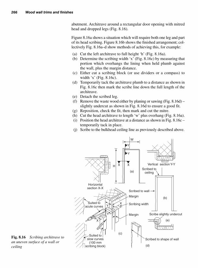
abutment. Architrave around a rectangular door opening with mitred
head and dropped legs (Fig. 8.16).
Figure 8.16a shows a situation which will require both one leg and part
of its head scribing. Figure 8.16b shows the finished arrangement; col-
lectively Fig. 8.16a–d show methods of achieving this, for example:
(a) Cut the left architrave to full height ‘h’ (Fig. 8.16a).
(b) Determine the scribing width ‘x’ (Fig. 8.16c) by measuring that
portion which overhangs the lining when held plumb against
the wall, plus the margin distance.
(c) Either cut a scribing block (or use dividers or a compass) to
width ‘x’ (Fig. 8.16c).
(d) Temporarily tack the architrave plumb to a distance as shown in
Fig. 8.16c then mark the scribe line down the full length of the
architrave.
(e) Detach the scribed leg.
(f) Remove the waste wood either by planing or sawing (Fig. 8.16d) –
slightly undercut as shown in Fig. 8.16d to ensure a good fit.
(g) Reposition, check the fit, then mark and cut the mitre.
(h) Cut the head architrave to length ‘w’ plus overhang (Fig. 8.16a).
(i) Position the head architrave at a distance as shown in Fig. 8.16c –
temporarily tack in place.
(j) Scribe to the bulkhead ceiling line as previously described above.
266 Wood wall trims and finishes
W
XX
Y
Y
H
X
XY
Y
Vertical section Y-Y
Scribed to ceiling
Scribed to wall
Margin
Margin
Scribing width
Scribe slightly undercut
Scribed to shape of wall
(d)
(e)
(b)
(a)
(c)Suited to
slow curves (100 mm
scribing block)
Suited toacute curves
Horizontal section X-X
Fig. 8.16 Scribing architrave to
an uneven surface of a wall or
ceiling

Architraves 267
(k) Remove the waste wood either by planing or sawing – slightly
undercut as shown in Fig. 8.16d to ensure a good fit.
(l) Reposition, check the fit, then mark and cut the mitre.
(m) Repeat the procedures as described in section 8.2.2.
As shown in Fig. 8.17a, where the architrave is thicker than the skirt-
ing board there is, unless the lower corner of the architrave needs
protection, no need for a plinth block. If, on the other hand, the skirt-
ing board is thicker than the architrave, and/or protection is required
(Fig. 8.17b), a plinth block is usually the answer (Fig. 8.17c).
8.2.4 Fixing plinthblocks (also known as‘Architrave block’, seealso Fig. 8.13)
(a)
(b)
(c)
(e)
(d)
Blockwork
Architrave thicker than skirtingboard – provides a stop end
Skirting board thicker thanarchitrave – unsatisfactory finish
Plinth block provides stop end forboth architrave and skirting board
Horizontal section
Approx. 6 mm(depends on width of ‘X’)
Hingeknuckle
Bare faced tenonhoused glued andscrewed to back of
plinth block
Door lining
150 mmmin.
Housing skirting board intoplinth block conceals any
shrinkage across plinth block
X
Fig. 8.17 Using a plinth block

As shown in Fig. 8.17d, plinth blocks are traditionally first fixed to the
architrave via a bare faced tenon glue and screwed to the back of the
block – the legs are fixed in the normal way. The block will then form an
end stop for the skirting board, the profile of which is usually housed into
the block. In this way any shrinkage gaps that may occur are shrouded.
Alternatively, both the architrave and the skirting board can be butted
against the block. In this way the block is fixed first, followed by the
architrave, then the skirting board.
The relationship between the architrave and the plinth block can
vary. An example is shown in the horizontal section in Fig. 8.17e.
Figure 8.18 shows a method and sequence of fixing architraves
around a wall serving hatch or ceiling access trap.
STAGE 1 – Marking out
(a) Mark a margin distance of about 3–5 mm around the opening;
(b) If there is any doubt as to the squareness of the opening (pay par-
ticular attention to ceiling openings), use a short end of archi-
trave to gauge the width at each corner to enable the true mitre
angle to be formed.
STAGE 2 – Left-hand architrave (a).
(a) Cut the bottom mitre;
(b) Hold firmly into position whilst marking the heal point of the top
mitre;
(c) Nail into position – leave nail heads to draw.
STAGE 3 – Head architrave (b)
(a) Cut and fit the left-hand mitre;
(b) Hold firmly into position whilst marking the heal point of the
RH mitre – cut the mitre and put to one side.
STAGE 4 – Bottom architrave (c)
(a) Cut and fit left-hand mitre;
(b) Hold firmly into position whilst marking the heal point of the
right-hand mitre – cut the mitre.
(c) Nail into position – leave nail heads to draw.
STAGE 5 – Right-hand architrave (d)
(a) Cut and fit bottom mitre;
(b) Hold firmly into position whilst marking the heal point of the top
mitre – cut the mitre.
268 Wood wall trims and finishes
8.2.5 Fixing architraves(four-sided openings)
Note: This procedure can be usedto find the mitre angle of any angle(both acute and obtuse)

STAGE 6 – Final assembly
(a) Hold (b) and (d) in position – check mitres (a–b, b–d, c–d) for fit –
adjust if required;
(b) Nail ‘d’ into position, then ‘b’;
(c) Ensuring that all the mitres are fair-faced, carefully nail across
each mitre;
(d) Complete the nailing pattern then punch all nail heads just below
the surface in preparation to receive any filler;
(e) Using a block plane remove a small arris (sharp corner) all round
the framework.
We have already seen how skirting boards form a decorative finish
between the wall and floor, and how they offer protection to the wall
against everyday activities like vacuuming the carpet or sweeping the
floor. The skirting board size (in particularly its depth) and moulding
details usually reflect the period in which the property was built.
A selection of commonly available moulded sections is shown in
Fig. 8.19 (also see Fig. 8.5). If wood is to be used, available lengths are
as for processed timber, for example, lengths will start at 1.8 m then
upwards in increments (multiples) of 300 mm up to a maximum
of 6.3 m.
Skirting boards 269
Stage 6
(a) (d)
(c)
(b)
Stage 5
(a) (d)
(c)
(b)
Stage 4
(a)
(c)
Stage 3
(a)
(b)
Stage 2
(a)
Stage 1
W
W Bisected angleproduces a true mitre
Fig. 8.18 Sequence of fixing architraves around wall and ceiling openings
8.3 Skirtingboards
Note: Figure 8.14 shows architravearound a rectangular door openingwith mitred head and dropped legs.

External and internal corners are dealt with differently. External corners
are mitred (Fig. 8.20), internal corners are scribed (Fig. 8.21). The main
reason for using a scribed joint is to minimize the shrinkage gap across
the width of the skirting board; remember that the greatest amount of
shrinkage across a section of timber takes place tangentially, followed by
radially and then finally the least is longitudinally (see Volume 1, section
1.7.2–3). Figure 8.22 shows how this can affect an internal mitre. The
amount of shrinkage will depend on the moisture content of the wood
on installation and the position of the growth rings, for example are they
predominantly across the width as with quarter sawn timber, or down its
depth as with tangentially sawn timber (see Volume 1, section 1.7.3).
8.3.1.1 The mitre
Very few corners are perfectly square, but just like those angles which
are acute (less than 90 degrees) or obtuse (greater than 90 degrees) the
mitres angle, as shown in Fig. 8.23 can be easily found, by bisection of
the angle. This is best done by using a mitre bevel board, which needs
to be between 75mm to 100mm wide and about 900mm in length.
The following method of bisecting any angle can be used to great effect:
1. Position the mitre board flat on the floor and up against one wall,
overlapping the corner by as much as its own width – mark off the
floor at its outer edges.
2. Reposition the board to touch the other wall and mark floor as
before.
3. By marking a line from the corner point of the wall to where the
outer lines intersect, the bisecting line will produce a true mitre line.
4. The mitre line can now be marked onto a bevel board ready to be
transferred to a sliding bevel.
270 Wood wall trims and finishes
Chamfer/round/
pencil (reversible)
BullnoseOvoloPencil
round
Torus/ovolo
(reversible)
Torus/ogee
(reversible)
Fig. 8.19 Commonly available
moulded sections used as skirting
board
8.3.1 Corner joints

Skirting boards 271
AA
B B
Plan of 90° true mitreExploded view of mitre
T
T
Fig. 8.20 Cutting a true mitre to
a 90° external corner
A
A
B
B
45° mitre cut
Plan of 90° true scribe
Exploded viewof scribe
Waste
Saw cut(coping saw)
Saw cut(tenon saw)
1
2
3
(b)
(a) (c)Mitred portion removed toreveal of reversed profile,
slightly undercut
5. This angle can be transferred direct to the skirting board, or used
as the angle for marking onto a mitre box.
8.3.1.2 The scribe
As we have seen, internal corners are scribed to reduce the effect of
shrink as can be seen from Fig. 8.21. Cutting a scribed joint is not as
straightforward as using a mitre. It involves several processes, for
example:
STAGE 1
Using a mitre box cut a true mitre as if to fit an internal corner. This
in effect will produce a front view of the skirting boards profile as
shown in Fig. 8.21a.
Fig. 8.21 Forming a true scribe
(reverse profile) to a 90° internal
corner

272 Wood wall trims and finishes
Gauge lath widerthan skirting board
Gauge lathparallel toface wall
Bisecting a 90° corner using a gauge lath
Floor mitre check lines
Marks on floor
Mitre bevel board Mitre bevel board
Transfer to sliding bevel
Fig. 8.22 Possible effect after
shrinkage at an internal corner
Minimalshrinkage gap
Width whenshrunk
Width onfixing
Plan viewshowing possible shrinkage
gap to an internal corner mitre
Plan viewshrinkage gap to an internal
corner scribed joint
Skirting board sawn sectiontogether with moisture content
affect amount of shrinkage
Quartersawn
Plansawn
Fig. 8.23 Using a mitre bevel
board to bisect angles

STAGE 2
Remove the waste portion (Fig. 8.21b and 8.21c). With the exception
of the top cut, cuts may be slightly undercut – this will ensure a
close-fitting joint.
STAGE 3
Before fixing offer the scribe up to the face of a short end of skirting
board to check to check the fit.
Whenever a moulding comes to a stop without an abutment its mould
is either returned to the wall it is fixed to or the floor it sits on.
8.3.2.1 Returned to wall
Fig. 8.24 shows two methods of returning the moulded profile. In
Fig. 8.24a the profile is cut across the end grain – this method is
known as a Mason’s mitre. The second method shown in Fig. 8.24b is
used with complex moulds and quality work: a true mitre is formed
with a short end of skirting board, which is glued and pinned together.
When set, the waste end is carefully cut back leaving a true return
without any end-grain exposure.
Skirting boards 273
Note: This method of cutting areverse profile can be used on anymoulded profile; curved sectionsare generally cut away with theuse of a coping saw.
8.3.2 Stop ends
E E
E
Front elevation
Plan
(a)
Front elevation
Waste wood to be removed
Plan
Return mitre
Saw
(b)
Mason’s mitre
Fig. 8.24 Returning the end
profile of a skirting board
towards a wall
8.3.3 Lengtheningskirting board (headingjoints)
8.3.2.2 Returned to floor
Fig. 8.25 shows two methods of returning a moulded profile back
towards the floor. The first example (Fig. 8.25a) is only suitable for a
skirting board with a chamfered face, whereas Fig. 8.25b can be used
with any shape of mould – even the most complex.
Heading joints are only used where the run is too great for a standard
length of skirting board – with good planning heading joints can
often the avoided.
If such a joint is required, as shown in Fig. 8.26, it is formed by mak-
ing two accurate opposing 45° cuts using a mitre box. Great care is

required for this joint as any inaccuracy will be difficult to conceal.
The overlapping portion should face the main natural light source
(window) to reduce the effect of any shadow line. The joint is
secured by skew nailing.
Before any fixing takes place it is important to plan the sequence you
intend to follow – not only for economic reasons but to avoid cutting
a mitre and/or scribe at both ends. Two fixing sequences are shown in
Fig. 8.27.
In Fig. 8.27a the sequence follows a clockwise direction, whereas
Fig. 8.27b follows an anti-clockwise direction – only lengths numbered
three, seven, and nine have either a mitre or scribe at both ends.
Skirting boards are generally fixed to walls by nailing through the face
of a board. As shown in Table 8.2 the methods used can vary according
274 Wood wall trims and finishes
Front elevationFront elevation
PlanPlan
45°
(a) (b)
E
E E
Fig. 8.25 Returning the end
profile of a skirting board back
towards a floor
8.3.4 Fixing skirtingboards
Note: Always ensure that any con-cealed services (electric cables,etc.) are detected (see section8.9) before any fixings are made
To face main light source
Front elevation
Plan
45° mitre cut
Screwnail
Hidden nailFig. 8.26 A lengthening or
heading joint

Skirting boards 275
1
2
3
11
10 8
9
7
6
5
4 A
(a) Clockwise cuttings
(b) Anti-clockwise cuttings
8
7
6
11
10 1
9
2
3
4
5 B
Fig. 8.27 Possible sequences
for arranging and fixing skirting
board
Table 8.2 Wall trims and finishes (mouldings) in relation to their use
Wall base material Fixing medium Fixing Comments
Brickwork Plastic plugs Screws Various Proprietary makes
Brickwork Direct † Masonry Goggles must be nails worn
Breeze (clinker) Direct † Masonry Goggles must be blocks nails wornBreeze (clinker) Plastic plugs Screws Various Proprietary blocks makesAerated concrete Direct Cut clasp Not readily blocks nails availableAerated concrete Special Plastic Screws Various Proprietary blocks plugs makesMost base Special Wall Adhesion Various Proprietary materials Adhesive makes
Note: As a general rule the length of the fixing is usually 21⁄2 � thethickness of the material to be fixed.† Masonry nails should penetrate the base material by not less than 25 mm.

276 Wood wall trims and finishes
Knee pad
Kneeler board(short end of floorboard)
Fig. 8.28 Adding pressure to a
‘sprung’ length of skirting board
prior to fixing
to the different types of base material used for walls (see also Volume 1,
section 12, Fixings devices).
Fixing centres can vary – with long lengths 600 mm centres are usu-
ally adequate.
More often than not the skirting board will be slightly sprung in its
length. It will therefore need to be pushed to the floor before being
fixed. As shown in Fig. 8.28 a short end of board (kneeler board) can
be used for this purpose.
If, as shown in Fig. 8.29a, the floor is uneven and a close fit is
required then it can be scribed similar to architrave. However, a word
of warning – you should always bear in mind that if you reduce the
depth of the skirting board at the ends (Fig. 8.29b and 8.29c), the
lengths of the abutting skirting boards should be reduced to bring them
in line. The alternative is to increase the depth of the skirting board to
be scribed by gluing a strip of timber to the under side (Fig 8.29c).
Then, by using an offcut of the strip as a scribing block, scribe the
skirting board to the floor.
As shown in Table 8.1 the two rails commonly fixed around a room
are the ‘dado’ and ‘picture rail’. The dado rail can have two main
functions: firstly to divide the height of the room into two horizontal
areas, and secondly as a means of protecting the wall from being
damaged from chair backs and wall furniture, hence the reason for
calling it a ‘chair wall rail’, or possibly a ‘waist rail’ because it is
usually situated at about waist height. Figure 8.30 shows four typical
dado sections.
8.3.5 Scribing skirtingboards
8.4 Rails arounda room

Rails around a room 277
Offcuts of scribing blockused as packings
(a)
(b)
(c)
Added strip Offcut of strip usedas scribing block
Added strip
EE
E
W
W
W
Scribing block
Note: In most cases the end depth ‘W’, should not be altered (cut away) as at (b)
Fig. 8.29 Scribing skirting board to an uneven floor
Fig. 8.30 Examples of shaped
sections used as dado rails
Picture hanger (hook)
Fig. 8.31 Examples of shaped
sections used as picture rails
Originally, the primary function of the picture rail (Fig. 8.31) was to act
as a bracket for a picture hook from which a picture was hung – these
could be very large and heavy so their fixings were very important.
Today, picture rails, just like dado rails, are often provided more as a
decorative feature.

Figure 8.32 illustrates the importance of taking a datum line around
the room. There are several methods of striking this line (see Volume
2, section 1.7) including:
(a) Traditional spirit levels;
(b) Digital spirit levels;
(c) Water levels;
(d) ‘Cowley’ automatic level;
(e) Laser levels.
Once this level line is struck – ideally as the top line of the dado rail –
this can be repeated at the picture rail height. It can be easier to use a
‘gauge rod’ cut to the filling height – this should be kept and marked
‘template’ as it will be useful at a later stage when, assuming that a
dado rail is to be fixed first, the picture rail is fixed to the wall.
The same principles as those used for the skirting board will apply.
When corners have to be bisected, the methods shown in Fig. 8.23
can still be used, but if there are wall units covering the floor at this
point use two short ends of board hand held across the corner instead
of laying them on the floor.
The same methods as those shown in Fig. 8.24 can be used. If, how-
ever, a complicated shape is to be returned in the solid then, as shown
in Fig. 8.33, the profile can be marked from the back. Then very care-
fully cut away the waste wood with a coping saw; with its blade set
to cut on the pull stroke, ragged edges on the face mould can be
avoided. The shape can then be finished with a sharp chisel and abra-
sive paper held round the appropriate former.
278 Wood wall trims and finishes
8.4.1 Setting out
8.4.2 Treatment atcorners (see alsosection 8.8, Rakingmoulds)
8.4.3 Stop ends
Filling height gaugerod (template)
Picture railunder edge
Dadotop edge
DatumlineDado height Datum
line
Important: consider these points whensetting filling height gauge rod
Note: When levelling the dado datum line, do not take the height from the skirting board, as this may not be level. (See Vol. 2, Section 1.6 & 1.7)
Fig. 8.32 Setting out walls of a room for fixing dado and picture rails

Rails around a room 279
Lengthening joints should always be avoided; the picture rail should
never be joined in its length. Dado rails can be joined by using adja-
cent 45° cuts as shown in Fig. 8.26.
The sequence described in section 8.3.4 for fixing skirting boards
will still apply, as well as the types of fixing used as shown in Table
8.2. Concealed proprietary snap fixing suitable for dado rails is avail-
able – a typical example is shown in Fig. 8.34 (they should be fixed
according to the manufacturer’s instructions).
8.4.4 Lengtheningdado and picture rails(heading joints) (seealso section 8.3.3)
8.4.5 Fixing rails
Using a coping saw to cut onthe ‘pull, not push’ action
Direction of cut
End profile markedon the back face
Endelevation
Front elevation
Plan view
Marking and cutting a return end
Fig. 8.33 Scribing and cutting a
dado returned stop end
Fig. 8.34 Proprietary concealed
fixing device for fixing dado rails
Note: Special regard should begiven to fixing picture rails as theoccupants could decide to use themas they were originally intended, i.e.for hanging pictures and mirrorsfrom. These could be extremelyheavy so it is important to take thisinto account at the fixing stage.

These shelves were originally designed to display ‘Delftware’ plates,
which typically have a blue decoration on a white background. They
are usually associated with hallways or dining rooms where they sup-
port ornamental plates or ornaments to good effect, out of harm’s way.
They can very often take the place of a picture rail.
Figure 8.36a shows a modern design, whereas Fig. 8.36b and 8.36c
illustrate two classical designs – all have dentil bracket supports.
Sizes range from 100 mm by 100 mm to 150 mm by 150 mm; they are
usually fixed to the wall by using screw and plugs. Figure 8.36d
shows how the fixings can be concealed behind a bracket.
Cornices are more usually associated with plasterwork where wall
meets ceiling, or the finish around the top of a wall or cupboard unit.
There are, however, occasions were we can use a cornice to head wall
panelling or independently as a feature, and as a means of housing
concealed lighting to illuminate the freeze area (Fig. 8.1) of a room.
280 Wood wall trims and finishes
8.5 Delft (plate)shelf (Fig. 8.35)
8.6 Cornice(drop or falsecornice)
Plate groove (stop)
Bracket (dentil)
(a)
(d)
(b) (c)Fixing to wallbehind bracket
Front elevation Use this bracketto conceal wall fixing
Fig. 8.36 Different Delft shelf
designs
Fig. 8.35 Example of the use of
a Delft shelf

Figure 8.37 shows examples of cornice arrangements capable of con-
cealing fluorescent tubes. The illustration in Fig. 8.37a is made up of
two runs of moulding and a shelf, whereas Fig. 8.37b is built up of a
wall plate with a horizontal board, dentil brackets and moulded cap-
ping boards.
This type of framework is purely decorative. Traditionally this work
was undertaken by the plasterer using a fibrous plasterwork tech-
nique (a skill still used today). However, a less expensive alternative
is to use a wood moulding. Figure 8.38 shows examples of the type
of profile that could be used for this purpose. There is a great variety
in proprietary decorative mouldings on the market, which also
include those which have been embossed or even carved.
The infill panel arrangements can vary greatly in their design, usu-
ally to suit the decor of the room. Figure 8.39 shows how corner details
may vary. In Fig. 8.39a a basic 45° mitre cut is made, whereas in Fig.
8.39b the mitre is formed by bisecting the angle as shown in Fig.
8.21. The mitre for the quadrant at Fig. 8.39c is more complex. In
this case, as shown in Fig. 8.39d, the mitre line is developed using
geometry to produce a curved mitre line. Had a straight cut been made,
the abutting moulding detailing would not have met up as shown in
Fig. 8.39e. Alternatively, as shown in Fig. 8.39f, the curved moulding
is widened to meet the requirements at ‘X’.
Infill panel frame 281
8.7 Infill panelframe
Fluorescentlighting tube
Wall plate
Bracket(dentil)
(b)
(a)
Steel back bracket
Steel fixingplate
Fig. 8.37 Wood cornice with
concealed lighting

Methods of fixing the moulding to the wall really depend on their
section size, length and condition (i.e. if they have any slight distor-
tions). For example, the light sections of moulding may be stuck to
the wall using a suitable panel adhesive. Heavier or longer sections
will require mechanical fixings (Table 8.2).
Moulding trims inclined at an angle (raking moulds) are used to even-
tually join up to one or more different levels to provide continuity of
the moulding. In this case we are concerned with raking moulds
which continue around a corner. Three examples are given below and
shown in Fig. 8.40.
282 Wood wall trims and finishes
(a) (a) (c)
W
W
W
(d)
W
W
X
(d)
(f)
(e)
45° mitre
X � Extra wide to enablemouldings to match at mitre
Curved mitreline to enable
mouldingsto match
Fig. 8.39 Corner details for an
infill panel
Machine-cut moulds Embossed(pressed) mould
Machine carvedFig. 8.38 Available mouldings
for constructing infill panels
8.7.1 Fixing panelmouldings
8.8 Rakingmoulds (Fig. 8.40)

Raking moulds 283
Front elevation
Frontelevation
Endelevation
Endelevation
Plan Plan
(a) One raking two level (b) Two raking square in plan
Front elevation
End elevation
Plan
(c) One raking one level non-square in plan
Fig. 8.40 Possible arrangements for raking moulding
1
1
2
2
3
3
4
4
5
5
678
9
Front elevation
Raking mould
Raking mould
Section of raking mould
Front elevationof mitre
Front elevation
End elevation
Projectionpoints C
Projection points A
0 to 5
0
12
34
5
0
Plan
1
1
2
2
3
3
4
4
5
5
6
89
0
7
Rake of mouldLevel m
ould
Section of level mould
Plan
0 to 5
Projection points B
0 to 5
b′
b″
a′
30°
Top edge bevel cut for raking mine
123
45
0
b′
b″
a′
Note: Projection points of A, B and C are the same distance apartFig. 8.41 Raking moulding –
bevel and section details
(a) One raking and two level – square in plan (Fig. 8.40a);
(b) Two raking – square in plan (Fig. 8.40b);
(c) One raking one level – non square in plan (Fig. 8.40c).

284 Wood wall trims and finishes
In these situations it would not be advisable, or indeed practicable, to
use the same section timber for both the level and inclined mould, if
the moulds are to correctly meet at the corner mitres.
Figure 8.41 illustrates a method of finding the bevel for the back of
the moulding, the top edge bevel for the inclined mitre, and the
required profile of the inclined moulding if the overall profile detail-
ing is to meet at the mitre joint.
Figure 8.42 shows a method of using the same section mould, either
level or inclined throughout, by inserting a small level mould before
and/or after each corner mitre – internal scribed, external mitred.
The face mitres for the level and inclined moulds are formed by
bisecting the angles (see Fig. 8.23).
Fig. 8.42 Raking moulding
in situ
8.9 Detection ofservices
Before any refurbishment or new work is carried out, carpenters and join-
ers must always be aware of the possibility of any hidden services, particu-
larly electrical ones which may be hidden behind existing partitions or solid
walls – coming into contact with live cables while fixing could be fatal.
However, there are various battery operated devices on the market that
are capable or detecting electrical cables, pipework and timber studs.
One example is shown in Fig. 8.43.
Using the various modes settings, it is capable of detecting and locat-
ing any brickwork, concrete and wooden structures before drilling
work commences.

Detection of services 285
Fig. 8.43 Bosch Wallscanner
D-Tect 100
References
Health and Safety at Work Act (HSAWA) 1974
The Construction (Health, Safety and Welfare) Regulations 1996
BS EN 923: Adhesives. Terms and definitions.
BS EN 1186–2: 1988, Timber for, and workmanship in joinery.
Specification for workmanship.
BS 8417: 2003, Preservation of timber – recommendations.
BS 5973: 1993, Code of practice for access and working scaffolds and
special scaffold structures in steel.
BS 1139–3: 1994, Specification for pre-fabricated access and working
towers.
BS 1139–4: 1982, Specification for pre-fabricated steel splitheads and
trestles.
BS 1129: 1990, Timber ladders, steps, trestles, and lightweight stagings.
BS 2037: 1994, Aluminium ladders, steps, and trestles for the building
and civil engineering industries.
BS 2482: 1981, Specification for timber scaffold boards.
BS 5973: 1993, Section 9 – tying to buildings.
Graphic display
Display lighting
Mode button
On/Offswitch
Measurementbutton
Handgrip
Front elevation
Operating displaymode
Centre point ofdetected object
Middle line of theD-tect 100
Area not yetsearched
Graphic display
Outer edges ofthe D-tect 100(dashed lines)
Surfacedisplay
Searched area
Drilling depthscale
Possible hiddenobjects
Alignment aid
Bosch Wallscanner D-tectin use – detecting metal
pipework

In relation to the internal finishes of a building, these areas of work
are used for practical and economical reasons to cover or resurface
structural and non-structural items, which either are not in keeping
with their surroundings and/or provide fire protection in accordance
with the Building Regulations.
The term ‘casings’ usually refers to the framework, facework, and
trim which go towards forming an enclosure into which service pipes,
cables, steel and concrete beams and columns, etc., are or could
be housed. Figure 9.1 shows examples of where casings are often
found.
These steel beams – often referred to as ‘binders’ – are used within
intermediate framed floors to reduce the effective span of bridging
joists, just as purlins are used within the roof structure to reduce the
span of roof rafters. A floor using one of these beams would be known
as a ‘double floor’, one using two beams as a ‘triple floor’, and so on.
Structural steelwork will have to be clad to protect it from the effects
of fire – the amount of fire resistance will depend on the location and
function.
Suitable materials which contribute to fire resistance include concrete,
plaster (coated plasterboard), and non-combustible boards. Board
materials will require some form of groundwork onto which they can
be fastened.
Casing-in and wall panelling
9
9.1 Casings
9.1.1 Steel beams(binders)

Casings 287
Figures 9.2 and 9.3 show how timber groundwork can be formed and
fixed around a steel universal beam (UB) to receive a fire-protective
boarding.
Encasement support (Fig. 9.2) will require either:
(a) A series of cradles fixed at centres of 450 to 600 mm, depending
on the sectional size of any counter battens or panel thickness;
(b) Framed grounds to both sides of the beam and its underside.
Reinforced concretecolumn or steel
universal column
Reinforced-concrete beam or steel universal beam
Half-column
Skirting boardover pipe-board/box
Cornerpipe-board/box
Wall pipe-board/box
Fig. 9.1 Examples of situations
requiring casing (casings)
Decking Floorjoist
Nogging to carryplasterboard
CradleBearer
UB
Bearerbolted to
beam
Cradlecarriessoffit
Alternativecorner joints
for cradle
Runner
Clip
Cleat
Fig. 9.2 Timber cradles and
grounds for casing a partially
exposed steel beam
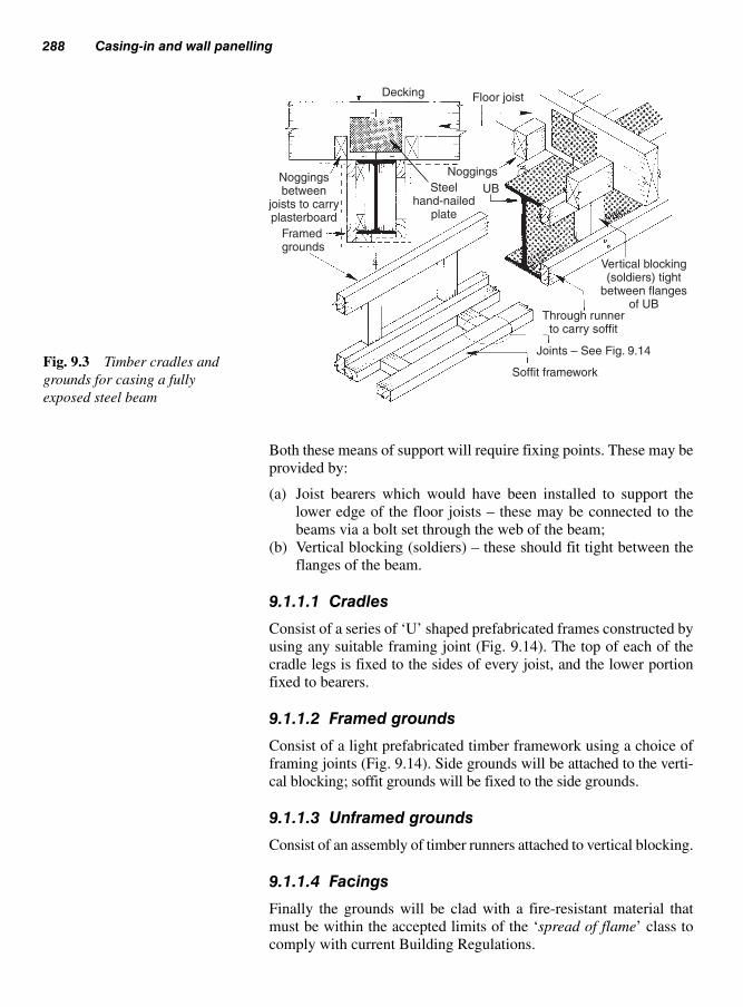
288 Casing-in and wall panelling
Both these means of support will require fixing points. These may be
provided by:
(a) Joist bearers which would have been installed to support the
lower edge of the floor joists – these may be connected to the
beams via a bolt set through the web of the beam;
(b) Vertical blocking (soldiers) – these should fit tight between the
flanges of the beam.
9.1.1.1 Cradles
Consist of a series of ‘U’ shaped prefabricated frames constructed by
using any suitable framing joint (Fig. 9.14). The top of each of the
cradle legs is fixed to the sides of every joist, and the lower portion
fixed to bearers.
9.1.1.2 Framed grounds
Consist of a light prefabricated timber framework using a choice of
framing joints (Fig. 9.14). Side grounds will be attached to the verti-
cal blocking; soffit grounds will be fixed to the side grounds.
9.1.1.3 Unframed grounds
Consist of an assembly of timber runners attached to vertical blocking.
9.1.1.4 Facings
Finally the grounds will be clad with a fire-resistant material that
must be within the accepted limits of the ‘spread of flame’ class to
comply with current Building Regulations.
Decking Floor joist
Noggings
Steelhand-nailed
plate
Framedgrounds
UB
Vertical blocking(soldiers) tight
between flangesof UB
Through runnerto carry soffit
Joints – See Fig. 9.14
Soffit framework
Noggingsbetween
joists to carryplasterboard
Fig. 9.3 Timber cradles and
grounds for casing a fully
exposed steel beam

Casings 289
In this case, before any grounds are assembled it is good to check for
any discrepancies in beam size. Timber grounds will be attached to
the beam using a method approved by the building designer – this
may involve using a cartridge operated fixing tool (Volume 1, section
8) to drive the hardened steel pins into the concrete.
Figure 9.4 shows an optional arrangement for fixing the grounds. Either:
(a) Two side frames and an under beam frame would be used; or
(b) The under beam framework has been dispensed with to allow the
facing soffit material to bridge between them. In this case extra
care must be taken to ensure that the facing materials are in line
and the soffit width is uniform along its length.
Groundwork can then be clad to enhance the beam’s appearance or to
match with a ceiling, providing it meets and complies with current
Building Regulations in relation to surface spread of flame, etc.
These can be dealt with in much the same way. With the exception of
three-sided half-columns (divided by a wall), timber groundwork can
be self-restraining. Figure 9.5 shows two alternative ways of fixing
timber grounds to a steel column. If provision has been made for bolt-
ing timber blocks between the flanges, groundwork may be necessary
on only two sides (Fig. 9.5a), otherwise blocks can be trapped
between the flanges (Fig. 9.5b) to act as fixing and stabilizing points
for the groundwork, which envelopes the whole column as shown.
Casing a concrete column is shown in Fig. 9.6. A set of four framed
grounds is made-up so that, when they are together as shown, their
Framed groundsfixed to beam
Casing
Reinforced-concrete floor slab
Framework fixed via woodinserts cast into the concrete
Note: Steel reinforcement not shown
Reinforced-concrete
beam
Alternative methods(with or without soffit framework)
Fig. 9.4 Fixing timber grounds with or without soffit to a concrete beam
9.1.3 Steel columns
9.1.4 Concretecolumns
9.1.2 Concrete beams

290 Casing-in and wall panelling
interconnecting internal dimensions are slightly larger than the column.
Before proceeding, however, checks must be made to ascertain the
largest cross-section of the column to ensure that the framework will be
slightly oversize at all points. Slight adjustments can then be made by
using stopped packings between the face of the column and the backs
of the grounds. These packings must be prevented from falling down
behind the grounds, if, or when more likely, shrinkage takes place due
to moisture movement. Therefore, as a precaution, a nail can be driven
into the packing – just above the cross member as shown in Fig. 9.6.
Steel universalcolumn
(UB) – stanchion
Fire protection(casing)
Rebateduprights
screwed toblocks
Firmed groundsscrewed to blocking
Alternativeblocking arrangements
Cross-membersnotched into
frame uprights
Blocking wedgedtight between flanges
(b)
(a)
Block bolted throughsteel column (stanchion)
Fig. 9.5 Fixing timber ground
around steel columns
Thin packing(hardboard,
plywood, etc.)
Protruding nail headprevents packingfrom sliding down
Framed grounds (boxed)screwed together, plumbed,then tightened against faceof concrete with packings
Enlarged detailFig. 9.6 Fixing timber grounds
around a concrete column

Casings 291
Steelwork, although non-combustible will lose structural strength and
distort in temperatures at about 800°C. Steelwork must therefore be
protected from heat generated by fire for a specific period of time to
enable a compartment or building as a whole to be safely evacuated.
To achieve this integrity structural steelwork must be able to attain a
prescribed period of fire resistance. This may be obtained either by
spraying with a fire resistant coating and/or being encased with a
non-combustible material. Materials such as gypsum-based plaster-
board, and many other proprietary products manufactured specif-
ically for this purpose, could be used.
In the main, pipes and cables are hidden from view – provision for
them having been made within a hollow floor or in purpose-made
ducts in both the floor and the walls. There are, however, situations
where such services have to be brought out on to the surface, and it is
in these situations that provisions such as those shown in Figs 9.7 and
9.8 can be applied.
Figure 9.7a shows how a pipe-box can be formed behind a skirting
board. It is always an advantage if the front is detachable, either fully or
over the greater part of its length – access is then possible without undue
damage to decorations if maintenance or ‘add-ons’ are required. Where
edge joints occur ‘veeing’ not only makes them less obvious but also
aids dismantling – a trimming-knife (with the blade retracted to its min-
imum) can simply be run along the joint to cut the film of paint or var-
nish. By under bevelling the edge or edges of the pipe-board, the joint
between the wood and the plaster is keyed and is less apparent.
Figure 9.7b and 9.7c deal with situations where pipes or cables are
sited vertically. Provided the pipe-boards have been fixed to the walls
at the first fixing stage of construction, forming a detachable casing as
shown is relatively easy. However, before front covers (casings) are
fixed, it is important to ensure that where the pipes, etc. pass through
the ceiling and/or floor, this area is suitably sealed to form a cavity
barrier (fire stopped), thereby preventing the passage of flame.
Otherwise, in the event of a fire, gaps could let the ducting act as a
flue, allowing fire to spread rapidly between floors.
Where a backboard (pipe-board) is not provided at the first fix stage,
the arrangements shown can be modified by fixing timber grounds
directly to the walls as shown in Fig. 9.8.
Front boards (inspection covers) should be screwed into position –
the use of screw cups and/or domes (see Volume 1, Table 12.6) is
recommended.
9.1.5 Fire resistance
9.1.6 Casings forservice pipes andcables
Important Note: Where servicespass through a ceiling or wall of afire-resistant construction anygaps or openings around thesepipes or cables, etc. must beproperly fire stopped and sealedbefore they are encased or hidden

292 Casing-in and wall panelling
In situations where a detachable facing is not practicable for fear of
disturbing and damaging a decorative finish, then some form of
access trap may be more desirable. Figure 9.9 gives some examples
on how simple access traps may be provided which will allow access
to regulating or stop vales.
The access traps themselves, may be opened via a hinge or similar,
and held closed by the use of magnetic catches.
Other materials may include a plastic cap to fit into an access hole.
V joint
Pluggedto wall
Pipe-board Floor coveringAlternative seat for
skirting board(a) Detachable casing – using skirting board as facing
Cover
Pipe-board
Detachableboxedcasing
(b) Detachable corner casing
Plasterwork
Detachable cover board
(c) Detachable face of wall casings
ScrewScrew cup
Bevelled keyfor plasterwork
Service pipes
Cleat fixedfrom within
casing
Note: Pipe-board fixed to wall at first-fixing stage of building construction. All ducts must be sealed where they meet walls, floors and ceiling
Fig. 9.7 Casing around service pipes and cables

Casings 293
Vertical section through adetachable skirting board
Horizontal section through a cornercasing with detachable facing
Horizontal section througha detachable wall casing
Horizontal section through a wallcasing with detachable facing
Note: Stop or regulating values should always have a means of access
Fig. 9.8 Casing in pipes without a pipe backing board
Front elevationsBottom hung traps (piano hinged)
– with magnetic touch catches
Vertical sectionstoptap behind skirtingboard – hinged access
Stoptap
Stoptap
Wall
Stoptap
Plastic plug(coffee jar top etc.)
Plug
Stoptap
Vertical sectionCircular plastic plug
Wall
Three options
Fig. 9.9 Accessing a stoptap behind skirting board

294 Casing-in and wall panelling
Suspended ceilings are now mostly constructed from lightweight
proprietary systems which use a grillwork of extruded or pressed
metal sections on to or into which panels of plasterboard, fibreboard,
or plastics either sit or are slotted. These systems are outside the
scope of this book – if further information is required, refer to the
British Gypsum handbook and other trade literature.
Wall panelling may be used to:
(a) Conceal unsightly services or uneven surfaces;
(b) Provide a decorative feature;
(c) Provide hygiene and easy clean surfaces;
(d) Provide special acoustic properties;
(e) Incorporate thermal installation;
(f) Provides a resilient and hardwearing surface.
Fig. 9.10 Examples of false-
work and panelling
Three-quarter-heightwall panelling
False (suspend)ceiling
Full-heightwall panelling
Bath panelling
Step/seat
Plumbing
Waist-height‘dado’ panelling
Window and door linings (see Chapters 3 and 4) may also be referred
to as ‘casings’ just as double-hung sash windows, which use weights
housed within a ‘cased’ or ‘boxed frame’, are sometimes called
‘cased window frames’.
Broadly speaking panelling may, like, many items of temporary
work, or work which replaces or otherwise serves as a permanent
substitute for the original surface, may be regarded as “falsework.”
Figure 9.10 shows how falsework may be used as a ‘cover-up’. For
example, the ceiling is false and is suspended from the floor or roof
above to mask pipework or heating ducts, etc. The wall panelling in this
case has been fixed over the plastered or self-finished walls to mask the
original surface. Purpose-made bath panels to cover the plumbing sys-
tem are nearly always available as an optional extra with the bath, but
there are instances where these cannot be used, for example with partly
sunken baths or raised baths with a stepped frontage.
9.1.7 Other casings
9.2 Wallpanelling
Note: Because of its temporarynature, items of formwork (Vol. 2,Chapter 3) are also referred to as‘falsework’
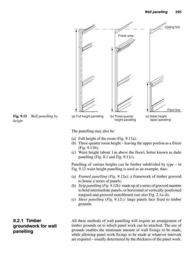
Wall panelling 295
The panelling may also be:
(a) Full height of the room (Fig. 9.11a);
(b) Three-quarter room height – leaving the upper portion as a frieze
(Fig. 9.11b);
(c) Waist height (about 1 m above the floor), better known as dado
panelling (Fig. 8.1 and Fig. 9.11c).
Panelling of various heights can be further subdivided by type – in
Fig. 9.12 waist height panelling is used as an example, thus:
(a) Framed panelling (Fig. 9.12a): a framework of timber grooved
to house a series of panels;
(b) Strip panelling (Fig. 9.12b): made up of a series of grooved muntins
to hold intermediate panels, or horizontal or vertically positioned
tongued-and-grooved matchboard (see also Fig. 2.1a–d);
(c) Sheet panelling (Fig. 9.12c): large panels face fixed to timber
grounds.
All three methods of wall panelling will require an arrangement of
timber grounds on to which panel work can be attached. The use of
grounds enables the minimum amount of wall fixings to be made,
while allowing panel work fixings to be made at whatever intervals
are required – usually determined by the thickness of the panel work.
Ceiling line
Frieze area
(a) Full height panelling (b) Three-quarter height panelling
(c) Waist height ‘dado’ panelling
Floor line
Fig. 9.11 Wall panelling by
height
9.2.1 Timbergroundwork for wallpanelling

296 Casing-in and wall panelling
There are two main types:
● Unframed;● Framed.
Unframed grounds (Fig. 9.13a): consist of a series of timber laths
individually fixed to the wall at pre-determined centres; these may be
positioned vertically or horizontally. Grounds must be fixed plumb
and in line (use of a straight edge or builders line, see Volume 2,
section 1.2) – great care must be taken to ensure that internal and
external angles are always plumb.
Framed grounds: a prefabricated open framework of timber jointed
and assembled as shown in Fig. 9.13b. Grounds should be plumbed
and levelled with the aid of wood or plastics packing, then fixed to
the wall via plugs or direct fixings. The use of nails or screws will
depend on the plug type and base material.
Raised and fielded solid panel
Panel (Manufactured board)
Simulated framed panelling (planted)
Flush
Framed
(c) Sheet panelling
A
C
1 unit
(a) Framed panelling
T & G matchboard
Plywood-strip panelsExamples of horizontal section B
(b) Strip panelling (vertical or horizontal)
B
Examples of horizontal section A
Examples of horizontal section CFig. 9.12 Three types of waist
height (dado) panelling

Wall panelling 297
The use of cartridge operated fixing tools (Volume 1, section 8.3)
may be considered if the base material is suitable.
Whether individual or framed grounds are used (Fig. 9.13) will depend
on the base material and the amount and type of panelling. In any
case (with the exception of strip panelling), grounds should be posi-
tioned behind each vertical and horizontal joint. The number of inter-
mediate grounds and the distance between them will depend on the
permitted span of the panelling material.
Grounds for dado and three-quarter panelling can be bevelled, as
shown in Fig. 9.19, to form a key for plaster. Suitable tee joints for
framed grounds are shown in Fig. 9.14; corner joints should be
adapted accordingly. Venting behind panels via groundwork is essen-
tial where rooms are liable to be subjected to high humidity. Vents
may be sited at about skirting board height and extend to the height of
the panel. They must not extend into the ceiling or floor (false or oth-
erwise) otherwise, in the event of a fire, the venting channels could
act as a flue and cause the fire to rapidly spread to other rooms.
Fixings may be made by one or a combination of the following methods.
Concealed drop-on fixings (Fig. 9.15) illustrates four methods:
(a) Tongued blocks (plywood buttons) screwed on to the rear face
of the panelling and dropped into edge-grooved groundwork
(Fig. 9.15a);
(b) Cranked metal plates screwed on to the rear face of the panelling
and again using grooved groundwork (Fig. 9.15b);
(c) Bevelled blocks cut to fit over bevelled grounds (Fig. 9.15c);
(a) Individual grounds(unframed) (b) Framed grounds
Fig. 9.13 Unframed (individ-
ual) and framed grounds
9.2.2 Fixing panellingto timber grounds

298 Casing-in and wall panelling
(d) Slotted metal plates fixed to the rear of the panel work, allowing it
to be dropped on to protruding screw heads set at pre-determined
centres (Fig. 9.15d).
Finally, slot screwing as described in Volume 1, section 10.2.1e may
also be used.
9.2.2.1 Concealed face fixings
Figure 9.16 shows several methods of concealing face fixings. The
use of screws is most common, but nail heads can be concealed in a
Plywood gussetor steel plate(to wall side)
Mortised and tongued (through and/or stub
tenons)
Halving joint
Plywood web glued into groove
Grooved stub – tenoned and
webbed
Fig. 9.14 Framing joints for
framed grounds
Wallpanel
Wall panel
Wall panel
Base material
Cranked steel hanger
Hardwood orplywood block
Round-head screw
Slotted steelscrew-plate
Vertical grounds
Horizontal grooved grounds
Horizontal bevelled grounds
Bevelled hardwood block
Slot cut in panel
(c)
(d)
(a) (b)
Fig. 9.15 Fixing panels using
drop-on fixings

Wall panelling 299
similar way. The best methods are to use a bead (Fig. 9.16a), a fillet
of wood or plastics (Fig. 9.16b), or a cover lath (Fig. 9.16c). The use
of counter-bored holes plugged with pellets cut across the grain of a
matching species of wood is another alternative (Fig. 9.16d).
9.2.2.2 Panel adhesives and adhesive pads (Fig. 9.22)
These are most suited to lightweight panelling – manufacturers’ instruc-
tions should always be consulted with regard to their use and appli-
cation. If the wall surfaces are sound and plumb, timber grounds may
in some cases be dispensed with.
Often referred to as ‘traditional’ panelling, this is made up of a series
of framed units consisting of a framework of grooved or rebated solid
timber (usually joined together with mortises and tenons), which
houses one or more solid or plywood panels. Panel shapes are often
as shown for panelled doors (see Fig. 4.14).
Traditional panel work is usually made of hardwood and is prefabri-
cated in the workshop into unit sizes suitable for safe transportation
and easy access into the premises in which it is to be fixed. Examples
are shown in Figs 9.12a and 9.17. Units are normally partly polished
before they are fixed and are finished on site when the danger of sur-
face damage is at a minimum.
This type of panelling can have the effect of making walls appear longer
or taller, depending on whether the boards are laid horizontally or
vertically. The direction of the groundwork will predominately be at
right angles to the run of the strip panelling.
9.2.3 Framed wallpanelling
(a) (b)
Cover bead
Wood or plastics fillet
(c)
CoverlathMachined pellet strip
Pellet Flush Domed(d)
Fig. 9.16 Concealing face
fixings
9.2.4 Strip wallpanelling (Fig. 9.12b)

300 Casing-in and wall panelling
Wood in the form of tongued-and-grooved boards or plywood is the
most common strip material, but metal and plastics profiles are also
popular. Reference should be made to ‘External cladding’ (Chapter
2) for the different profiles and methods of concealing the fixings.
Figure 9.18 shows two examples of secret fixing vertical or horizon-
tal tongued-and-grooved boarding (strip panelling).
This modern panelling – often referred to as ‘flush’ panelling – con-
sists of manufactured boards in their natural state or faced with
another material. For example, typical base materials would include
blockboard, laminboard, MDF, plywood, particle boards (chip-
board), and different fibreboards such as softboard (insulation
board), medium boards, and hardboards. Finishes such as polished
wood veneers, stainless steel, brushed aluminium, plastics, plastics
laminates, and various woven fabrics are very popular.
Figure 9.19 shows vertical sections through three heights of sheet
panelling. The full-height panelling (Fig. 9.19a) is left short at the top
to allow for ventilation if needed and is covered by a scribed fillet or
cornice. If a suspended ceiling is to be incorporated, allowance can
also be made at the head. The plinth is recessed.
9.2.5 Sheet wallpanelling (Fig. 9.12c)
Frieze area A
A
B B
Front elevation (three-quarter panelling)
Framed grounds
Panel bottom rail
Skirting
Vertical blocks behind skirtingPilaster Skirting continuesaround the pilaster
Muntin
Horizontal section B-B Vertical section A-A
Built-up cornice withconcealed strip lighting
Panel top rail
Panel mid-rail
Raisen & fielded panel
F.F.L
Fig. 9.17 Traditional frieze height framed panelling

Wall panelling 301
The three-quarter panelling (Fig. 9.19b), shows how concealed strip
lighting can easily be set into (behind) the cornice to illuminate the
frieze and ceiling. A skirting board has been used to cover the gap
left under the panelling, which can be used to ventilate the back of
the panelling.
Secret nailing
Horizontal sections
Proprietaryfixing clip
Secret fixing using proprietary clips
Fig. 9.18 Secret fixing tongued-
and-grooved boarding
Fri
eze
Acrylic dust-cover
Part vertical elevation
Striplight
Suspendedceiling
CorniceGroundsbevelled toform key
for plaster
Dado
Waist(dado)- height
Three-quarter-height
Full-height
( ) (b) ( )
Fig. 9.19 Vertical sections
through sheet wall panelling at
different heights

302 Casing-in and wall panelling
Tongued-and-grooved Extruded metal or plastics sections
Fig. 9.21 Sheet panelling
internal external corner details
(a) Loose tongue or tongue-and- groove
(b) Rebated with infill of wood, metal, or plastics
(c) Extruded metal channel with optional infill
(d) Extruded metal ‘I’ section – as tongue
(e) Extruded metal ‘I’ section – forms groove for panelsFig. 9.20 Fixing sheet panelling
Figure 9.19c shows how a dado rail trims the top edge of the dado
panelling.
Different methods of joining panels vertically are shown in
Fig. 9.20. Figure 9.21 shows how internal and external angles can be
treated.
Thin sheets of suitably faced plywood or fibreboard may be used as
panelling for reasons of lightness or economy. Figure 9.22 shows some

Bath panelling 303
possible methods of fixing them to the base material and of making
sheet-to-sheet connections with or without the use of timber grounds.
If a fire breaks out within the confines of a room with walls and ceil-
ing clad with a combustible material, it is obvious that the risk of
flames spreading over the surfaces will be much greater than if they
had been covered with a non-combustible material like plaster.
Therefore, because many of the materials used for wall panelling are
to some extent combustible, limitations are in some cases put on their
use, unless they are suitably treated with a fire retardant to satisfy
current Building Regulations.
Rate of flame spread and its classification are discussed at Chapter 2,
section 2.2.6, Fire performance.
The type of panel will depend on where the bath is sited in the room,
for example:
(a) With only one long side exposed;
(b) With one long side and one end exposed;
(c) With two long sides and one end exposed.
Capping
Packing
Adhesive padsor paneladhesive
Timber grounds
Extruded metal/plastics‘I’ section
Extruded metal/plastics sectionwith flexible cover fillet
Cover lath
Butt-joint connections
Without timbergrounds
With timbergrounds
Vertical sections
Horizontal sections
Fig. 9.22 Fixing thin sheet
panelling
9.4 Bathpanelling
9.3 Fireperformance (rateof flame spread)

304 Casing-in and wall panelling
We are going to consider two types of panelling:
● pre-formed panels made from various materials;● panels built-up in-situ.
9.4.1.1 Pre-formed panels (Fig. 9.23)
These usually only require a small-sectioned timber plate attached to
the floor as a restraint and to provide a means of fixing the bottom
edge of the panel or toe piece. The top edge is held in place by a
groove formed by a pre-fixed timber or metal section stiffened to the
underside of the rolled edge of the bath. The arrangement and fixing
of the stiffener can vary between makes of bath.
9.4.1.2 Built-up bath panels (Fig. 9.24)
These will require a supporting timber back framework constructed
with simple framing joints (Volume 1, section 10.3) secured to the
under edge of the bath stiffener and the floor. It is important that
these frames are not over-tightened between these points otherwise
Wall fixing
Timber bath edge frame(edge stiffener)
Acrylic bath
A
Bath edgedetail
A
Base board
Adjustable legs
Vertical section through bath, and side panel
Metal stirrups – support baseboard and bath edge frame
Plinth (toe piece)
Proprietary pre-formedbath side panel
Metal stirrup
Preformed side panel
Floor fixing for plinth(timber plate)
Preformed end panel
Horizontal section A-A
Fig. 9.23 Fixing pre-formed
bath panel

Bath panelling 305
there will be a tendency to lift the front edge of the bath and possibly
cause it to distort.
The panelling material can be attached to this subframework. The
panel material may be in the form of a framed, strip, or sheet panel
(see sections 9.2.3–5), with various decorative finishes.
Metal bath
A
Bath edgedetail
Top rail fit underbath edge rim
Raised panel
Plinth set back
Vertical section through bath and side panel
Floor fixing for plinth
Plinth
Plan view Horizontal section – ‘A’
End & side panel corner detail
� Centre lineFig. 9.24 In-situ built-up
bath panel

306 Casing-in and wall panelling
References
BS 1282: 1999, Wood Preservatives. Guidance on choice use and
application.
BS 4261: 1999, Wood Preservation, Vocabulary.
BS 5589: 1989, Code of practice for wood preservation.
BS 5707: 1997, Specification for preparations of wood preservatives in
organic solvents.
BS 476–7: 1997, Fire tests on building materials (surface spread of
flame).
BS EN 634–2: 1997, Cement-bonded particle board, specification.
BS EN 636: 2003, Plywood specifications.
BS 5973: 1993, Code of practice for access and working scaffolds and
special scaffold structures in steel.
BS 1139–3: 1994, Specification for prefabricated access and working
towers.
BS 1139–4: 1982, Specification for prefabricated steel splitheads and
trestles.
BS 1129: 1990, Timber ladders, steps, trestles, and lightweight stagings.
BS 2037: 1994, Aluminium ladders, steps, and trestles for the building
and civil engineering industries.
BS 2482: 1981, Specification for timber scaffold boards. Building
Regulation Approved Document B, Fire safety: 2000.
BS 5973: 1993, Section 9 – tying to buildings.
HSE Information Sheet General Access, Scaffolds and Ladders
Information Sheet 49.
Building Regulation Approved Document B, Five Spread: 2000.

Examples of how some domestic fitments may appear are shown in
Fig. 10.1. It is usual for each group of fitments to be named accord-
ing to their location, for example:
(a) kitchen fitments;
(b) bathroom fitments;
(c) bedroom fitments.
Fitments are, of course, found in other areas of the home, such as a
lounge or a dining room but, because their use is often multi-purpose,
they are less specifically named. Such an item could consist of a fit-
ted base or wall unit – even a shelved room-divider – which might at
sometime be expected to house among other things a television, video,
and/or hi-fi systems.
Joiners can also be expected to fit out offices, workshops, and ware-
houses of industrial premises. Commercial premises such as shops
and banks, etc. usually employ specialist shop fitters, kitchen fitters
or joinery firms which specialize in purpose-made joinery products.
Broadly speaking, joinery fitments can be divided into six groups:
● Shelving: these are fitted between alcoves or supported on uprights;● Free-standing units: these stand off the floor without added support;● Hung units: these rely upon a wall and/or ceiling for support;● Fitted units: these are ‘free-standing’ or ‘hung’ units which –
because of possible instability when in use or the need to fit close to
a wall, floor, ceiling, or another unit – require fixing to whatever
they abut;● Built-in fitments: these rely fully or in part upon their attachment
to a floor, wall, or ceiling, or a combination thereof, for the forma-
tion of the structural framework and/or the stability of the fitment
(Fig. 10.9).
Joinery fitmentsand purpose-made joinery
10

308 Joinery fitments (purpose made joinery)
Wall shelving
TablesFolding
table/shelfFloor
cupboard
(Base units)
Sink unit
Wall cupboard
Wall – fixed
Wall vanity unit
Headboard andside units
Floor unitbookcases
Cupboard/shelfroom dividers
Tall cupboards wardrobesFig. 10.1 Examples of some
joinery fitments
Shelves are expected to support the differing weight-to-volume ratios
of a vast variety of items and materials. It is therefore essential that,
before shelves are constructed or assembled, consideration is given to
both their function and location as these are the essential factors that
must be integrated within the overall design.
Figure 10.2 a shows the dangers of:
(i) using shelving of inadequate thickness or strength to withstand
the necessary imposed loads; or
(ii) expecting shelving to span an unrealistic distance.
Figure 10.2b and 10.2c can be regarded as suitable remedial alterna-
tives, i.e. providing the necessary intermediate support and/or using
stronger material.
Shelves are made up of either ‘solid’ or slatted material, examples of
which are shown in Fig. 10.3 (see also Volume 1, section 10.2.). Over the
years, various methods of supporting shelves have evolved which the
joiner can adapt to suit their specific requirements. A few examples of
10.1 Shelving
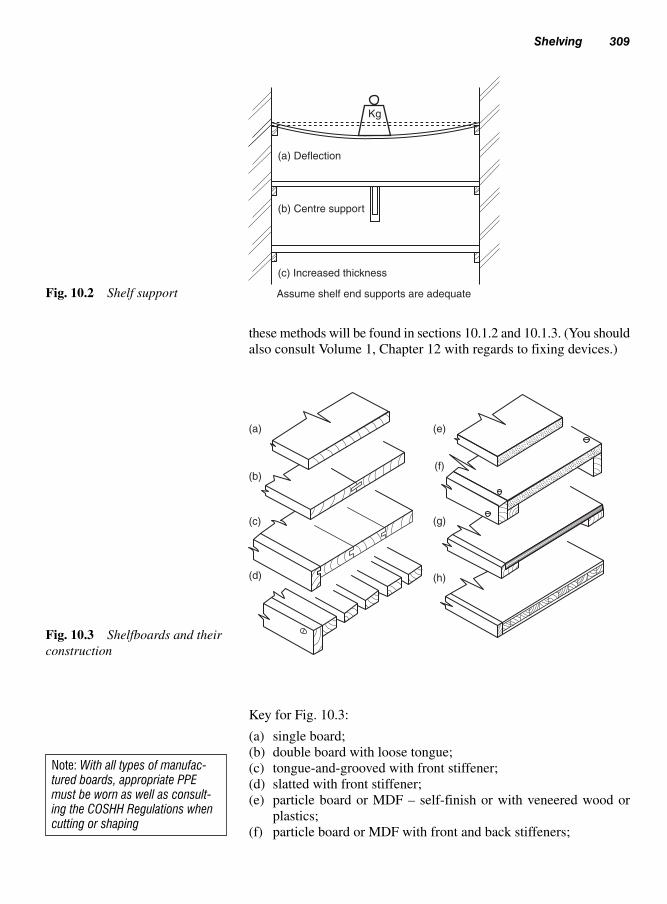
Shelving 309
(a) Deflection
(b) Centre support
Kg
(c) Increased thickness
Assume shelf end supports are adequateFig. 10.2 Shelf support
these methods will be found in sections 10.1.2 and 10.1.3. (You should
also consult Volume 1, Chapter 12 with regards to fixing devices.)
Note: With all types of manufac-tured boards, appropriate PPEmust be worn as well as consult-ing the COSHH Regulations whencutting or shaping
(a)
(b)
(c)
(d)
(e)
(f)
(g)
(h)
Fig. 10.3 Shelfboards and their
construction
Key for Fig. 10.3:
(a) single board;
(b) double board with loose tongue;
(c) tongue-and-grooved with front stiffener;
(d) slatted with front stiffener;
(e) particle board or MDF – self-finish or with veneered wood or
plastics;
(f) particle board or MDF with front and back stiffeners;

310 Joinery fitments (purpose made joinery)
(a)
(b)
(c)
(d)
Fig. 10.4 Traditional methods
of shelf support and assembly
10.1.2 Traditionalshelving
(g) plywood or MDF with front stiffener and back support;
(h) blockboard or laminboard with slipped front edge.
As can be seen from Fig. 10.4, shelves can be supported by:
(a) bearers fixed to wall;
(b) brackets – metal, or purpose-made from timber and/or plywood;
(c) timber – framed uprights (standards);
(d) solid uprights (enclosed units), where provision for shelf adjust-
ment can be made.
The methods in Fig. 10.4a and 10.4b rely on walls for their support,
whereas those in Fig. 10.4c and 10.4d may be free-standing units.
Commercially produced forms of shelf support may follow a similar
pattern to those in Fig. 10.4b and 10.4d, but provide for greater flexi-
bility, in both their construction and the means of shelf adjustment.
Figure 10.5a shows how metal brackets of various styles and sizes
can be positioned to any height by hooking them onto an upright
metal channel which has been secured to a wall. Figure 10.5b shows
how a series of holes bored in a solid upright enables metal or plastic
shelf-supporting studs and their sockets to be positioned to suit shelf
10.1.3 Proprietarysystems and shelving aids

requirements. Alternatively, a metal strip can be housed or surface
fixed with adjustable pegs as shown in Fig. 10.5c.
The following considerations should always be taken into account
before any work begins. First, it is necessary to ensure that fitment
heights suit the user, i.e. an adult, a child, or in some cases a dis-
abled person. All work surfaces, cupboards, and shelving in regular
use should be easily accessible without the need for excessive bend-
ing or stretching. Wall-cupboard doors should be made to slide,
unless they can be hinged opened without the risk of a person acci-
dentally walking into an open door. Tall narrow units should be
fastened back to a wall or up to a ceiling to prevent them toppling
over – such units are particularly at risk when all the hinged doors
are open. (There has always been this danger with some free stand-
ing wardrobes – especially if they have heavy mirrored doors.)
Secondly, the width and length of fitments are important, especially
when units are designed to house sinks, vanity basins, or gas or elec-
trical appliances. If base units are to be backed, then an allowance of
not less than 50 mm should be left between the back and the wall for
pipe-work and skirting board, etc. Figures 10.6 and 10.7a and b give
some guidance as to various accepted unit sizes.
Finally, the type and method of construction should be considered, as
below.
Designing fitments 311
(a)
(b) (c)
Fig. 10.5 Proprietary methods
of shelf support
10.2 Designingfitments

750
450
800 – 1200
300 – 600 50 – 100
910 –
922
500
300
300
300
600
722
2056 –
2092
600
Note: Sizes will vary between manufacturersFig. 10.6 Guide for sizing
kitchen fitments
430
450 572 – 900 900 900
Dressing table Tallboy Wardrobe
570 – 590
End elevation
300
2260
2092
700
1064
Bridging unit
Note: Sizes will vary between manufacturers
(a)
600 – 900
Front elevation
450 – 500
End elevation
760 –
800
450
300 –
700
100
Shelved and
mirrored door
wall unit
Base
vanity
unit
Note: Dimensions will vary
(b)
Fig. 10.7 Guide for sizing bedroom and bathroom fitments
‘Carcase work’ generally refers to the main framework of the whole
unit but – because they form part of the main framework with some
methods of construction – the top and plinth sections will also be
dealt with under this heading.
10.2.1.1 Worktables
As shown in Fig. 10.8, there are four main considerations:
(i) the joint between the rails and the table legs;
(ii) whether to include tie rails;
(iii) whether to include a drawer or drawers;
(iv) how to attach the table top.
By mortising the rails into the legs (Fig. 10.8a) a strong joint can be
made. Its strength is determined by the rail depth (tenon depth) and the
leg section (tenon length) – effective length is increased by mitring
the ends of each tenon as shown. The use of a top mid-rail (Fig. 10.8b)
dovetail-housed into the front and back rails will depend on the table
length.
A much simpler method of corner jointing is shown in Fig. 10.8c,
which uses a Crompton table-plate to hold the rails in position. The
legs are bolted to the plate via a steel washer and a wing-nut – studs
having previously been screwed into the corner of each leg. The main
advantage of this method is that the legs can be easily dismantled at
any time simply by unscrewing the wing-nuts.
Tie rails prevent table legs from spreading. Legs placed upon smooth
surfaces like a vinyl-covered floor will stress the joints between the
rails and legs, particularly if the legs are splayed. Therefore, pro-
vided they do not impede the users’ leg room, ties will prove an asset.
Drawers can be included within the design, but can add considerably to
the overall cost of the table. Figure 10.8d shows how the construction
can be modified to include table-top drawers. The way in which the
table-top is attached will depend on what material the top is made of
and whether there is any likelihood of moisture movement of the top
after fixing. Manufactured boards (Fig. 10.8e) present little difficulty,
therefore any of the methods shown in Fig. 10.8g could be adopted. On
the other hand, if a solid timber top (suitably jointed) was required (Fig.
10.8f), then rigid fixings using pockets and blocks should be avoided.
Round-head screws through steel washers should be used where steel
movement plates meet the underside of the table-top. Turn-buttons are
screwed to the underside of the table-top, then – when the top is in
position – the buttons are turned until their tongues fit into the grooves
or slots cut into the backs of the top rails. The screws can then be
tightened.
Designing fitments 313
10.2.1 Carcaseconstruction

314 Joinery fitments (purpose made joinery)
Front rail or drawer
Front elevation Optional tie rails End elevation
End rail
Legs
(a)
Plywood or
hardwood
turn-button
(b)Mid-rail
Screwed via pocket
(c)
(g)
Plastics or
wood block
(d)
(e)
(f)
Plastics laminate – square edge
Plastics laminate – post formed
Tongued-and-grooved
Double tongue-and-grooved
Laminated timber
Front elevation of proprietory corner plate
Plan
Steel movement
(shrinkage) plates
Leg
Wing-nut
Table rails
Frame fixed with corner plates
Detachable from rails
Plan view of leg attached prior to securing with wing-nut
Fig. 10.8 General-purpose
work tables

10.2.1.2 Purpose made base units (free-standing orfitted)
Figure 10.9 shows four methods of constructing these units:
Boxed or rail-and-slab construction (Fig. 10.9a) is the method favoured
by most unit manufacturers. Base, ends, and intermediate upright pan-
els and shelving are all cut from sheet material – usually 16 mm thick
plastics-faced particle board. Modular sizes usually reflect standard
metric sheet sizes. Unit backs, which hold the unit square, are usually
made from pre-finished hardboard, particle board or MDF.
Designing fitments 315
Upright slab(standard)
Rail
(a) Boxed or rail-and- slab construction
(c) Skeleton-framed (front and back) construction
(b) Front-framed and slab construction
(d) Skeleton-framed (cross-frames) construction
Separate plinth
Half-lap cornerdetail
Base-unit
carcase
Double through –dovetail corner
detail
Top
Fig. 10.9 Methods of
constructing base units for fitted
or freestanding cupboards

Most manufacturers generally prefer to use proprietary knock-down
fittings (see Fig. 10.12b), which enable the whole unit to be packed
flat. All that is then required for on-site assembly is the ability to
understand the manufacturer’s drawings and usually the use of a
screwdriver or a special tool supplied. Originally these knock-down
fittings were available only to the manufacturers of assembly-line fit-
ments, but similar fittings are now freely available from most hardware
suppliers. The plinth may be separate or built into the carcase.
10.2.1.3 Front-framed and slab construction (Fig. 10.9b)
Again, the ends and intermediate upright panels are of sheet material.
A back is optional. The front is framed-up from small timber sections
(e.g. 25 mm � 50 mm) jointed by mortise-and-tenon and/or halving
joints. The plinth may be separate or built into the carcase.
10.2.1.4 Skeleton-framed (front and back)construction (Fig. 10.9c)
Front and back frames are joined to cross-rails which serve as shelf
bearers and/or drawer runners. The plinth is usually separate.
10.2.1.5 Skeleton-framed (cross-frames) construction(Fig. 10.9d)
Framed uprights serve as shelf-bearers or supports for drawer runners.
They are positioned to suit door or drawer lengths and are notched to
receive front and back runners. The plinth may be separate, but is usu-
ally formed by notching back to take a toe piece.
Figure 10.10 shows a unit made of manufactured board to include
housing joints to receive the fixed shelf and baseboard (traditionally
known as the potboard) which are glued, pinned and later filled with
a suitable filler.
To support the backboard of the unit, a groove is machined at the back
of each upright (or standard).
A front and back cross-rail may be included that has been dovetailed
into the top of the uprights for extra strength. Screws may be used
through these rails to assist with the fixing of the top rather than using
fixing blocks (Figs 10.8 and 10.10d).
Manufactured board often requires edging, as shown in Fig. 10.11
especially in the case of particle board or blockboard; for this reason
edgings of either natural wood (Fig. 10.10b) fitted into grooves along
all exposed edges, or plastic laminated strip (Fig. 10.10c) which are
applied by various means using heat. All these edged finishes should
fully match the unit.
316 Joinery fitments (purpose made joinery)

Figure 10.11 shows several arrangements for edges of panels.
Designing fitments 317
Rail stop-dovetailedinto standard for strength
Back board
Upright(Standard)
Shelf (fixed)
Baseboard
Plinth (For details seeFig. 10.12a)
Block detailssee Fig. 10.12b
Fixing blockfor plinth
Iron-onedging
(c)
(b)
(d)
(a)
HardwoodedgingNote: For sake of clarity,
back rail is not shown
Groove for backboard
Fig. 10.10 Cupboard unit with traditional jointing methods
Timber core
Framedflush panel
Edgedmanufactured
board
Lippedmanufactured
board
Framedpanel
Corrugatedfasteners
Note: See volume 1, 10.2.1
Fig. 10.11 Fabricating end
panels and divisions (standards
or uprights)
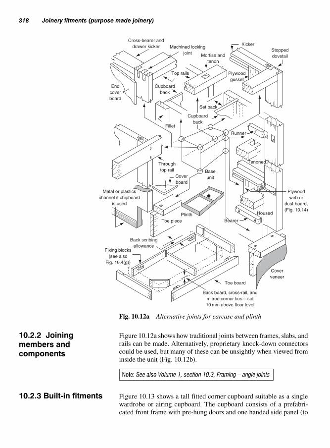
318 Joinery fitments (purpose made joinery)
Cross-bearer and
drawer kicker Machined locking
jointMortise and
tenon
Kicker
Stopped
dovetail
Plywood
gusset
Top rails
End
cover
board
Cupboard
back
Fillet
Set back
Cupboard
back
Runner
Tenoned
Base
unit
Bearer
Cover
veneer
Toe board
Back board, cross-rail, and
mitred corner ties – set
10 mm above floor level
Plinth
Toe piece
Back scribing
allowanceFixing blocks
(see also
Fig. 10.4(g))
Housed
Plywood
web or
dust-board,
(Fig. 10.14)
Through
top rail
Cover
board
Metal or plastics
channel if chipboard
is used
Fig. 10.12a Alternative joints for carcase and plinth
Figure 10.12a shows how traditional joints between frames, slabs, and
rails can be made. Alternatively, proprietary knock-down connectors
could be used, but many of these can be unsightly when viewed from
inside the unit (Fig. 10.12b).
Figure 10.13 shows a tall fitted corner cupboard suitable as a single
wardrobe or airing cupboard. The cupboard consists of a prefabri-
cated front frame with pre-hung doors and one handed side panel (to
10.2.2 Joiningmembers andcomponents
Note: See also Volume 1, section 10.3, Framing – angle joints
10.2.3 Built-in fitments

suit either left- or right-hand walls). Existing walls serve as a back
and the other side. The drawing shows two alternative types of door,
and the front frame can differ in the way that the bottom rail is attached
to the toe board when forming a plinth.
Both the front frame (without doors) and the side frame are plumbed,
then scribed to the walls. Positions of wall bearers (shelf positions)
and uprights are levelled, marked, and (where necessary) plugged to
the wall to receive shelves and the edge of the side panel. The front
frame is then fixed to the front edges of the shelves and the side panel.
The cornice or trim is then fixed between the cupboard and the ceiling,
then the doors are re-hung and the handles and catches are fitted.
It has always been regarded as a major achievement when an appren-
tice joiner can successfully make and fit, by traditional means, a
drawer into a pre-formed drawer opening, because the operation as a
whole requires a considerable amount of skill.
These should match the type of drawer. For example, Fig. 10.14
shows a cut-away view of a traditional drawer opening designed to
Wood drawers 319
Connectingbolt
(unit-to-unit)
Top corner fixingplate (back to wall) Camlock
Campost
Plastics corner block
Fig. 10.12b Joints for slab
construction using proprietary
fittings
10.3 Wooddrawers
10.3.1 Draweropenings

320 Joinery fitments (purpose made joinery)
Cornerwebs
Drawerrunner
Top fixing hole
KickerBack vent
Dust -board
Drawer stop – glued and pinned
Thickness ofdrawer front
Drawer rail
Fig. 10.14 Traditional drawer
openings
Cornice
A B
A B
C C
1500
70
2200
600
Airing cupboardor wardrobe
PlanScribe
Scribe
Flush door
500
25 × 50Bearer (battens)
fixed to wallSide panel
Note: Shelf not shown
Alternative horizontal sections C-C
25 × 40
25 × 40Bearer
25 × 40
25 × 50
50 × 25
25 × 75Toe board
12 mm Chipboard40 × 25 Laths
Lay-ondoor
Alternative vertical sections A-A and B-B
Alternative corner details
Plywood/Hardboard
Note: Timber sizes are sawn sizes (ex.)
Fig. 10.13 Fitted corner cupboard

house the whole of the drawer front (Fig. 10.15a). If the drawer
recess consists of solid sides, top, and dust-board bottom, the action
of the close-fitting drawer compressing the air behind it could make
drawer closing awkward, unless the drawer back is lower than the
sides or a vent hole is cut into the back of the carcase.
In all cases, the run of the drawer is checked by gluing and tacking
two hardwood or plywood drawer stops near the ends of each drawer
rail as shown.
Figure 10.15 shows how different fronts can be used. Figure 10.15a
may be set in line with or raised outside the carcase – it slides over a
bottom runner. Figure 10.15b is similar, but the drawer rail is set
back the thickness of the drawer front – in this way the drawer rails
within a nest of drawers (drawers set one upon another) may be omit-
ted or concealed. With single drawers, the overhang below the
drawer sides can be cut away to form a drawer pull. The drawer front
in Fig. 10.15c is sloping and drops below the sides; therefore the
drawer rail can again be omitted or concealed – the runners in this
case are inset midway into the drawer sides. Figure 10.15d has a drop
front to allow easy access to clothing, etc. and is often found within
a wardrobe.
Wood drawers 321
(a) (b)
(c)
(e)
(d)
Drop front – easy-access clothes etc. (mid-runner)
Bevelled front (mid-runner)
Flush or raised drawer front (bottom-runner)
False front (bottom or mid-runner)
Lapped over drawer rail (bottom runner)
Fig. 10.15 Types of drawer
front

10.3.1.1 Drawer runners (Fig. 10.16)
Traditionally, drawer runners were built into the main frame carcase,
and the bottom of the drawer sides slid over them, wood on wood
(Fig. 10.16a). Candlewax was used as a lubricant. Drawers in constant
use eventually became worn, with the result that the drawer front
became displaced.
Hardwood inset mid-runners (Fig. 10.16b) use a groove cut into the
drawer sides. They are also subject to wear.
Modern runners are available in many different forms. Some are made
from plastics (Fig. 10.16c) or of fibre-reinforced plastics (Fig. 10.16d) –
both give easy drawer movement. Others are made of metal, with inter-
vening steel or plastics ball-races to give the effort-free motion we asso-
ciate with the drawers of modern filing cabinets. Hardwood top-hung
322 Joinery fitments (purpose made joinery)
Drawer side
Runner
Kicker
Guide
Rigid PVC or fibre-reinforced plastics drawer
slides
Metal extending drawer runner – three-quarter
and full access
(a) (c)
(d)
(e)
(b)
Plastics runnersHardwood mid-runner
Side of carcase
Top side hung Mid-side hung
Vertical sections through alternative arrangements
Use of hardwood side and top hung drawer runners
(Stronger than top side hung)Top hung
Bench or unit topHardwood runner
Hardwoodrunner
Hardwoodguide
Drawer sides
(f)
Fig. 10.16 Drawer runners

track (Fig. 10.16f) is ideal for adding a drawer under a worktop or table,
but is only intended for use with shallow drawers with light contents.
10.3.1.2 Drawer joints (Fig. 10.17)
Drawer sides to a non-overhanging front will normally be dovetailed
(worked either by hand or by machine) and stopped (lapped dove-
tails) if the face of the drawer is to show, otherwise through dovetails
can be used. Overhanging drawer fronts can be trenched to receive a
dovetailed housing, or planted on as a false front to a through-
dovetailed framework.
The drawer back can be joined to the sides by using either through
dovetails or stopped housings. The drawer bottom fits into grooves
cut into the drawer sides and front (or into add-on beads as shown in
Fig. 10.18(5a)) and is then nailed on to the bottom edge of the drawer
back. Glue blocks are stuck between the sides and the bottom.
Wood drawers 323
(a)
(d)
Drawerfronts
Drawersides
Drawer bottom
Underside
Machineddovetails
(e)
Falsefront
(f)
Drawerside
Glue blocks10 to 12 mm
square
Drawer back
(b)
(c)
Drawerside
Note: Pins and dovetails are the same size
a: Stopped housing; b: Through dovetail; c: Stopped dovetail (lapped);
d: Machined dovetail; e: Dovetail housing; f: Through dovetails and false front.Fig. 10.17 Drawer joints

Modern drawers come nowadays, together with bedroom units, kitchens
units etc., usually ready assembled. Thus reducing the installation time
by qualified experienced fitters or the competent home owner.
The drawers are often made of MDF or particle board with a timber or
plastics laminated veneer with ball-bearing runners and cushion closers.
10.3.1.3 Drawer construction (traditional)
The following stages refer to those shown in Fig. 10.18.
324 Joinery fitments (purpose made joinery)
Remove twist(face side) Fit drawer front
2 mm
Bottomthickness
10 mm
Cut to length
Frontsidesback
12
3
4 5
6
75a
9
8
11
12 13
10
14
15
Drawer/cupboard lockDrawer-lock chisel
Planeflat
Lead-in
10–12
A
B
C
Stack
Glue
Baseboard
Held in vice
Grooving jig
Knock-in escutcheon
60
See volume 1,section 10.3.7
12 mm
Fig. 10.18 Stage-by-stage trad-
itional drawer construction
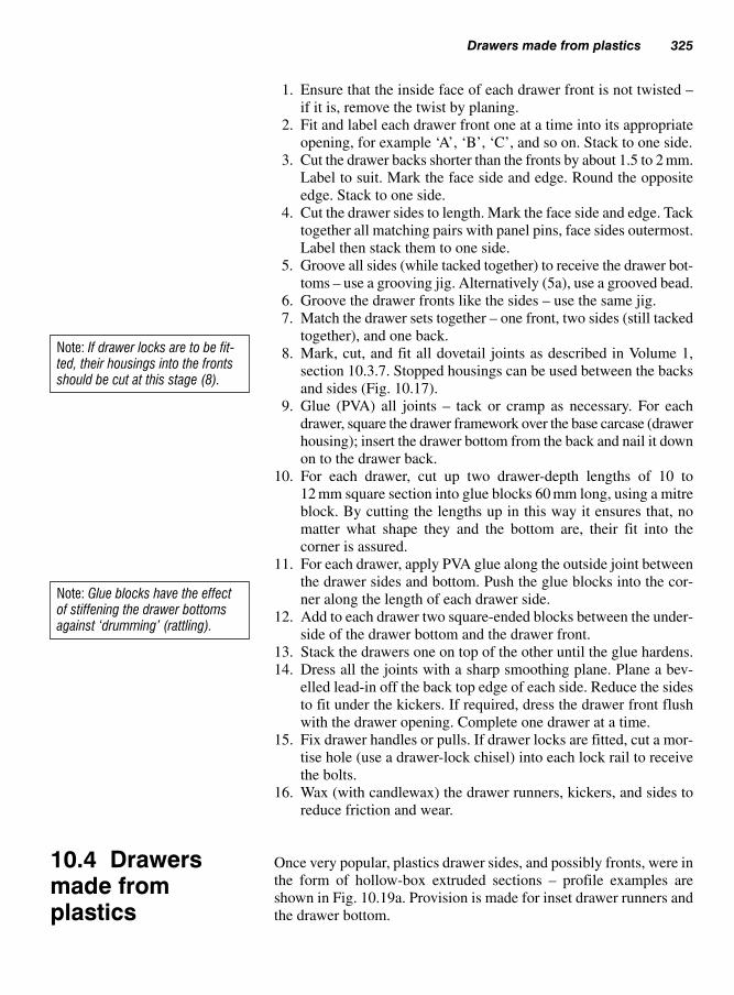
1. Ensure that the inside face of each drawer front is not twisted –
if it is, remove the twist by planing.
2. Fit and label each drawer front one at a time into its appropriate
opening, for example ‘A’, ‘B’, ‘C’, and so on. Stack to one side.
3. Cut the drawer backs shorter than the fronts by about 1.5 to 2 mm.
Label to suit. Mark the face side and edge. Round the opposite
edge. Stack to one side.
4. Cut the drawer sides to length. Mark the face side and edge. Tack
together all matching pairs with panel pins, face sides outermost.
Label then stack them to one side.
5. Groove all sides (while tacked together) to receive the drawer bot-
toms – use a grooving jig. Alternatively (5a), use a grooved bead.
6. Groove the drawer fronts like the sides – use the same jig.
7. Match the drawer sets together – one front, two sides (still tacked
together), and one back.
8. Mark, cut, and fit all dovetail joints as described in Volume 1,
section 10.3.7. Stopped housings can be used between the backs
and sides (Fig. 10.17).
9. Glue (PVA) all joints – tack or cramp as necessary. For each
drawer, square the drawer framework over the base carcase (drawer
housing); insert the drawer bottom from the back and nail it down
on to the drawer back.
10. For each drawer, cut up two drawer-depth lengths of 10 to
12 mm square section into glue blocks 60 mm long, using a mitre
block. By cutting the lengths up in this way it ensures that, no
matter what shape they and the bottom are, their fit into the
corner is assured.
11. For each drawer, apply PVA glue along the outside joint between
the drawer sides and bottom. Push the glue blocks into the cor-
ner along the length of each drawer side.
12. Add to each drawer two square-ended blocks between the under-
side of the drawer bottom and the drawer front.
13. Stack the drawers one on top of the other until the glue hardens.
14. Dress all the joints with a sharp smoothing plane. Plane a bev-
elled lead-in off the back top edge of each side. Reduce the sides
to fit under the kickers. If required, dress the drawer front flush
with the drawer opening. Complete one drawer at a time.
15. Fix drawer handles or pulls. If drawer locks are fitted, cut a mor-
tise hole (use a drawer-lock chisel) into each lock rail to receive
the bolts.
16. Wax (with candlewax) the drawer runners, kickers, and sides to
reduce friction and wear.
Once very popular, plastics drawer sides, and possibly fronts, were in
the form of hollow-box extruded sections – profile examples are
shown in Fig. 10.19a. Provision is made for inset drawer runners and
the drawer bottom.
Drawers made from plastics 325
Note: If drawer locks are to be fit-ted, their housings into the frontsshould be cut at this stage (8).
Note: Glue blocks have the effectof stiffening the drawer bottomsagainst ‘drumming’ (rattling).
10.4 Drawersmade fromplastics

The sides are cut to length and jointed with purpose-made corner blocks
which fit into the hollow-box section. The joint can be made by:
(a) glueing,
(b) using non-retractable barbed metal shores;
(c) using retractable click catches which fit into pre-mortised holes
cut into the drawer section. (These drawers are made to order by
the manufacturer.)
Drawer fronts (other than plastics) can be attached to the profile by
screws (Fig. 10.19c) or by omitting the front profile and using special
end connectors as shown in Fig. 10.19d – in which case the front will
have to have provision made to receive the drawer bottom.
326 Joinery fitments (purpose made joinery)
11 12 14 Easy-cleanprofile
80 to 1
38 m
m
41 to 1
80 m
m
80 to 1
40 m
mRunnergroove
3.4 mm
26Roller runners(a) Plastics-drawer side profiles
(b)
(d)
(c)
(e)
Drawer front
Carcaseside
5–10 mm clearancedepending on runner type
Runner
Fig. 10.19 Drawers made
from plastics
10.4.1 Assembly (Fig. 10.19b)

These range from simple plastics strips with bull-nose ends, screwed
or dowelled to the sides of the drawer housing (Fig. 10.19e), to those
with effortless action as a result of using rollers, ball-races and self-
close mechanism.
Doors may be inset, flush, or protruding in relation to the cupboard car-
case – much will depend on the door material and the front design of the
cupboard. Hinges are available to satisfy most door positions. Doors
can be hung on hinges or made to slide. Hung doors give quick, full, and
easy access into a cupboard, but when doors are open or being opened
they can be a hazard as mentioned earlier. Sliding doors, on the other
hand, can restrict cupboard access, since usually only half or one-third
of the front area can be opened at any one time.
Cupboard doors (Fig. 10.20) may be made by the following methods:
● Panelled doors (Fig. 10.20a) – a frame work of timber grooved on
the inside edges to receive a panel of wood, manufactured board or
safety glass (Fig. 10.20b) which must comply with current safety
legislation or regulations which relate to safety applications.
BS 6262-4: 1994.● Flush wood doors (Fig. 10.20c) – constructed of sheet material,
i.e. MDF, laminboard or blockboard, face one or both sides with
wood veneer with lipped edges all round.● Flush particle board doors (Fig. 10.20d) – made from chipboard
that has been faced and edged with melamine or laminated plastics.● Rebated doors (Fig. 10.20e) – timber framework faced with man-
ufactured board, i.e. plywood or MDF.
Cupboard doors 327
Fig. 10.20 Cupboard door materials
10.5 Cupboarddoors
10.4.2 Drawer runners
Safetyglass
(b)
(a) Panelled(c) Flush – Blockboard
or laminboard
(d) Flush – Chipboardfaced and edged
melamine or laminatedplastics
(e) Rebated – plywood orMDF on framed backing
Note: All panelled doors and flush doors may now be processed from MDF

Doors set inside their frame require butt hinges (Fig. 10.21a). For neat-
ness, uncranked butts can be set with only half of the hinge knuckle
showing – notice the lead-in on the closing edge of the door.
The two-leaf cranked hinge (Fig. 10.21b) allows a door to fit partly or
fully (with a ‘lay-on’ fitting) over the door frame. Open doors could
interfere with adjacent fitments.
328 Joinery fitments (purpose made joinery)
Lead-in
Rebated
Adjustingscrew
Locatingdowels
Locating dowel
Spring loadedconcealed cabinet hinge
Light dutybarrel hinge
Three-leaf hinge(cranked)
Two-leaf hinge(one cranked)
Solid-drawnbrass butt hinge
(a)
(b)
(c)
(d)
(e)
(f)
Plastics plug
Lay-on fixing
Lay-on fixing
Semi-concealeddouble-cranked hinge
(g)
Door dampener(face-fixed or insert)Fig. 10.21 Hanging cupboard
doors
10.5.1 Hangingcupboard doors (Fig. 10.21)

Three-leaf cranked hinges (Fig. 10.21c) can used with a rebated and
a lay-on fixing.
Barrel hinges (Fig. 10.21d) can be used on lift-off doors. They are fixed
by screwing the metal dowel either directly or via a plastics plug into
the edge of the door and the door frame.
Semi-concealed double-cranked hinges (Fig. 10.21e) allow similar
cupboard units to butt one against the other – outside door edges do
not interfere with adjacent closed doors.
Self-latching concealed hinges (Fig. 10.21f) do not interfere with adja-
cent doors. They have a built-in adjusting mechanism and are usually
self-closing over the last part of the closing arc.
The Soft-close door dampener mechanism shown at Fig. 10.21g is
fixed to the closing edge of the unit by two screws. Used with the
spring-loaded concealed cabinet hinge it prevents the cupboard door
from “slamming” shut, by the protruding piston that gently retracts
back into its cyclinder – different types are available.
Cupboard catches – different types are available as shown in Fig.
10.22, to suit different type and sizes of door.
10.5.1.1 Fitment furniture (Fig. 10.23)
When door or drawer edge grips are not used, handles or pulls should
be positioned so that the door or drawer opens or slides with ease and
should be sited at a convenient position to avoid over-reaching.
Bar handles, knobs, and pulls are attached with bolts or screws. Flush
pulls – associated with sliding doors – are recessed into the face of the
door. Door or drawer edge grips are extruded from aluminium or plas-
tics. Attachment is usually via a barbed tongue, which is gently driven
into the grooved edge of the door or drawer. The grooves should be
stopped short, and the tongues cut back so that they do not show on
the door edge or drawer end.
As shown in Fig. 10.24, arrangement of sliding doors will depend on
the number of doors and the overall opening size.
Thin sliding-door panels (Fig. 10.25) – whether glass, plywood, or
hardboard – use either grooves cut into their surrounding framework
(plastics inserts provide a smoother action) or purpose-made chan-
nels of plastics or fibre-reinforced plastics. Whichever method
is used, the top grooves will need to be deeper than the bottom
grooves, to enable doors to be positioned and lifted out for cleaning
purposes, etc.
Thicker and heavier doors can be run off a bottom- or top-track
system.
Cupboard doors 329
10.5.2 Sliding doors

330 Joinery fitments (purpose made joinery)
Striking-plate
Steel ball set in spring barrel
Ball catch
Plastics wheel or plunger catch
Lightweight door catches
Tension screws (top and bottom)
Adjustable double-ball catch
Magnetic door catches
Staple
Poles ofmagnet
Door leaf
Fig. 10.22 Cupboard catches
10.5.2.1 Bottom-track sliding-door systems
Figure 10.26 shows examples of how some of the bottom-track sys-
tems work. Arrangements at the top are such that they keep the door
from deviating from its straight path. This is achieved by pinning guide-
laths on each side of the door, or using a channel to house the top
edge of the door, or a retractable or non-retractable guide-pin.
Bottom arrangements include the use of nylon saddle slides (two per
door) to carry the door over the top of a ‘fibre’ track, which is either

Cupboard doors 331
Single track – one door Double track – two doors
Double track – three doors
Fig. 10.24 Arranging sliding
doors
Safetyglass doors
Top track deeper than bottom –allows doors to lift out
Handles either recessed or holes
with plastics inserts, or flush pulls
Aluminium channel with plastics inserts
Plastics-laminateinserts – to suit plywood
or hardboard doorsFibre or plastics channel
Channels for glass, plywood, or hardboard sliding doors
Fig. 10.25 Channels for thin
sliding doors
Domed cover Screw/bolt
Spike or teethprevent turning
KnobNut
Washer
‘D’ handle
Flush pull
Bar pull
Tongue
Tonguestopped short
Using door/draweredges as grips
Extruded aluminium section(there are many profiles)
Screw fixing
Washer
Fig. 10.23 Handles, pulls, and
grips
housed in or surfaced fixed. Alternatively, wheel runners can be used
over the same type of track. One problem with this arrangement is that
the base track stands proud of its base board – restricting cleaning.
This can in part be overcome by leaving the track short at each end.
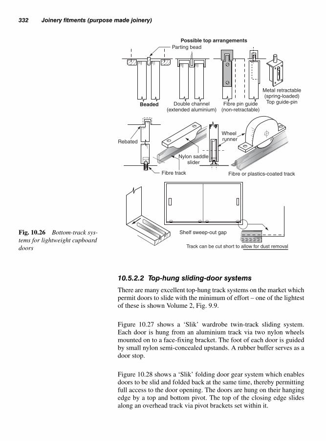
10.5.2.2 Top-hung sliding-door systems
There are many excellent top-hung track systems on the market which
permit doors to slide with the minimum of effort – one of the lightest
of these is shown Volume 2, Fig. 9.9.
Figure 10.27 shows a ‘Slik’ wardrobe twin-track sliding system.
Each door is hung from an aluminium track via two nylon wheels
mounted on to a face-fixing bracket. The foot of each door is guided
by small nylon semi-concealed upstands. A rubber buffer serves as a
door stop.
Figure 10.28 shows a ‘Slik’ folding door gear system which enables
doors to be slid and folded back at the same time, thereby permitting
full access to the door opening. The doors are hung on their hanging
edge by a top and bottom pivot. The top of the closing edge slides
along an overhead track via pivot brackets set within it.
332 Joinery fitments (purpose made joinery)
Possible top arrangements
Parting bead
Beaded
Rebated
Double channel(extended aluminium)
Fibre pin guide(non-retractable)
Metal retractable(spring-loaded)Top guide-pin
Wheel runner
Nylon saddleslider
Fibre track Fibre or plastics-coated track
Shelf sweep-out gap
Track can be cut short to allow for dust removal
Fig. 10.26 Bottom-track sys-
tems for lightweight cupboard
doors
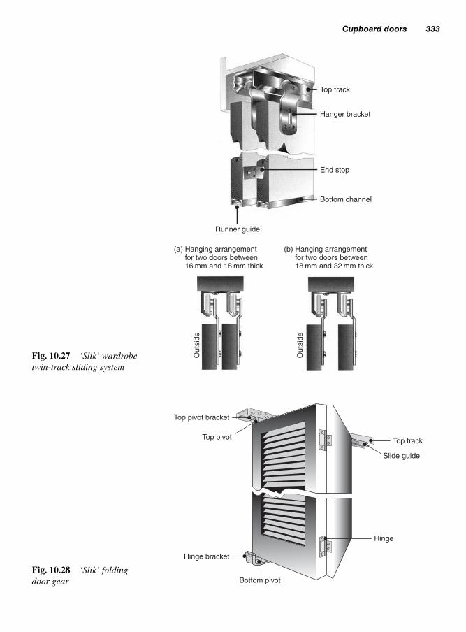
Cupboard doors 333
Top track
Hanger bracket
End stop
Bottom channel
Runner guide
(a) Hanging arrangement for two doors between 16 mm and 18 mm thick
(b) Hanging arrangement for two doors between 18 mm and 32 mm thick
Outs
ide
Outs
ide
Fig. 10.27 ‘Slik’ wardrobe
twin-track sliding system
Top pivot bracket
Top pivot
Bottom pivot
Top track
Slide guide
Hinge
Hinge bracket
Fig. 10.28 ‘Slik’ folding
door gear

Kitchen units nowadays are available ready assembled (reducing
installation time) in modular sizes to suit most kitchen appliances.
A method of installing the kitchen units is listed below and illustrated
in Figs 10.29, 10.30 and 10.31.
(i) Datum line (Fig. 10.29) A horizontal datum line (see Datums,
Volume 2, 1.6) is marked around the wall approximately 1 m
above the floor where the kitchen units are to be fitted. As the floor
may be out, it may be an idea to take a series of measurements to
determine the highest point (or shortest distance to the datum line)
of the floor. As appliances may be fitted into or under the units,
measure the height of the units from this point. Remember that a
refrigerator will need a ventilation gap at the top.
Adjustable legs are included with most modern units and are
adjusted to suit varying floor levels.
The required height for the units is marked on the wall (meas-
ured at the floors highest point) and transferred around the wall,
parallel to the existing datum line.
(ii) Worktop back support rail (Fig. 10.30) This rail (25 � 50) is
secured to this new line with plugs and screws, and will provide
a support to the worktop as well as a levelling point for the units.
(iii) Wall units (Fig. 10.31) At this point mark lines around the wall
to position the units, from the datum line (Fig. 10.29), allowing
334 Joinery fitments (purpose made joinery)
10.6 Kitchenunits
E3
E2
E�
E3
E2
E�
Back rail line
FFL (Finished floor level)
Upperwall unit
Wall unittop
(a) 1000Datum line
‘E’ � equal
(b)
Fig. 10.29 Fixing datum lines

Steel cornerfixing plate
Datum lineDatum line
Datum line
Tall wallcupboard unit
Wallcupboard
unit
(c)
(b)
(a)
Ceiling fixing Wall fixing
Preparing forwall fixing
End wallfixings
Dropdistance
Adjustablebracket dowelledto cupboard side
Hanging platescrewed to wall
Note: Bottom support brackets may be used
(d)
Fig. 10.31 Fixing wall units
Worktop back support rail
Worktop cut away for clarity
Gap forservices
Adjustable feet(legs) screwed
to floor
Units levelledfrom back rail
Unit back rail set down tosuit drawer line type units
Top rail to suit full cupboard units
Backclearance
Toe board plinthclip attaches to leg
Detachable toe board
Single unit
Double corner unit
Corner fillet
Double unit
Fig. 10.30 Fixing worktop base units

for the thickness of the worktop and ensuring adequate head-
room. If tall base units are to be included then these will deter-
mine the height of the wall units, if not, then it may be worth
considering fitting the wall units first, starting in the corner, if
corner units are included.
Wall units maybe levelled and secured onto timber battens with
corner fixing plates (Fig. 10.31(b) and fixed to the ceiling (Fig.
10.31(c)).
Proprietary adjustable fixings are the modern alternative as
shown in Fig. 10.31(a) end wall fixings shown at Fig. 10.31(d).
(iv) Base units (Fig. 10.30) Starting from the corner (if corner units
are included) position the units in place and level off from the
back support rail adjusting the leg as required. Allowance at the
back of the units provides for installation of services etc.
All base and wall units are secured together with proprietary screws
or bolts as shown in Fig. 10.12b.
After the units are fitted and levelled, the worktop may then be
placed in position to be joined (see Fig. 10.32).
This operation is carried out using a heavy duty electric router, tem-
plate, guide bush (see Volume 1, p. 190, Fig. 6.44), suitable straight
router cutter, and proprietary jig with locating pins which are secured
in place using small ‘G’ cramps – Fig. 10.33.
Sufficient personal protective equipment (PPE) must be worn during the
cutting process and an adequate extraction system fitted to the router.
Figure 10.32 shows the corner of the worktop that has been prepared
prior to assembly, including also the slots for the panel connectors
and biscuits for jointing and locating the tops together securely.
The necessary shaping of the joint is performed with a proprietary
jig, for example the ‘TREND’ worktop jig as shown in Fig. 10.33.
This versatile jig, together with an electric router and guide bush, can
be used to perform a number of required operations for different
worktop layouts using the locating pins.
When using a proprietary jig the manufacturer’s instructions must be
followed to ensure a good quality joint on the worktop.
Figures 10.33 to 10.35 show the stages of operations involved when
cutting and fitting the worktop.
After marking out the areas for cutting, the jig, which has been securely
fitted to the edge of the worktop, is used with the router to perform the
necessary shaping as shown in Fig. 10.33.
336 Joinery fitments (purpose made joinery)
10.6.1 Worktops

Kitchen units 337
Worktop jig
Locating pins
Fig. 10.32 The ‘TREND’ work-
top jig and accessories
Worktop jig
Note: Dust extraction system not shown
Fig. 10.33 Using the jig to form the joint
Panel connector
Fig. 10.34 Fitting the panel
connectors to the underside
workshop

The jig also includes facilities for forming the slots in each end of the
worktops to receive the panel connectors. After the worktops are jointed
together using a suitable adhesive, the panel connectors are then tight-
ened using the appropriate spanner.
Figure 10.34 shows how the panel connectors fit into the panel slots.
The last operation is to cut the slots to receive the oval shaped bis-
cuits that fit into the slots formed at both ends of the worktops. Once
the adhesive has been applied, they will swell up and ensure a tight
fit within each pre-formed slot.
A special self-guiding cutter is used with the router to form the slots for
the biscuits (Fig. 10.35). Alternatively, a biscuit jointer could be used.
10.6.1.1 Cutting apertures in worktop
Forming the aperture/s in the worktop for sink units or cooking hob
may be undertaken by the use of a jigsaw (see Volume 1, Chapter 6)
or router (if a template is made, see Volume 1, 6.15.3) after first care-
fully marking out the correct positions. Masking tape may be used on
the worktop for clarification of the marking out and to help prevent
breaking-out of the cut edges.
Always double-check marking out otherwise mistakes cannot always
be rectified after.
Figure 10.36 shows the cutting of an aperture by the use of a jigsaw
after first drilling 12 mm pilot holes in each corner as starting points. By
using a special down-cutting blade, break-out from the upper surface
can be reduced. A firm grip and downward pressure on the jig-saw is
recommended, otherwise there will be a tendency for the jigsaw to lift
during the cutting operation.
338 Joinery fitments (purpose made joinery)
Biscuits
Slot for biscuit
Slot for connector
Note: Dust extraction system not shown.Fig. 10.35 Forming the slots for
biscuit jointing

Finishes 339
All edges of the aperture must be sealed with an appropriate water-
proof sealant.
When all the units and worktop are fitted, the final operation is to fix
the finishes to the wall units. This may be in the form of cornices or
pelmets as shown in Fig. 10.37.
(i) Cornices – bind the units together at the same time providing a
continuous decorative finish across the units. Usually available
in 3 m lengths, either as a moulding of solid timber, or MDF cov-
ered with a decorative plastic laminate.
Using a purpose made mitre box, proprietary mitre box and fixed
saw or electric powered mitre saw – mitres are cut to the required
angle.
Mouldings must be held securely in the mitre box either by a
temporary screw or turn button.
To prevent break-out to the exposed edges, all cuts must be made
to the decorative face.
Particularly with solid timber, internal mitres are scribed (see Fig.
8.21) to minimise any shrinkage.
(ii) Pelmets – has similar functions to cornices by binding the units
together and providing a decorative finish, but also may conceal
electric lighting. Corners are mitred in a similar fashion to cor-
nices and fixed to the underside by means of various methods.
To prevent light leakage along the joints an opaque sealant is
used.
10.7 Finishes
Downward pressure
Special downwardcutting blade
Caution – there will be atendency for the saw to pushupwards as it cuts
Fig. 10.36 Worktop cut-outs

340 Joinery fitments (purpose made joinery)
References
Health and Safety at Work Act (HSAWA) 1974.
Control of Substances Hazardous to Health Act (COSHH) 1994.
BS 952–1:1995, Glass for glazing.
BS 4071:1996 (amended 1992): Specification of polyvinyl acetate
(pva) emulsion for wood.
BS 6206: 1981: Specification for compact requirements.
BS 6262–4: 1994, Glazing for buildings.
Provision and use of work equipment regulations (PUWER).
Workplace (Health Safety & Welfare) Regulations 1992:
Cornice
Mitre box
Turnbutton
Wedge
Top tie
Plan view of standard mitre box
A
A
Modified mitre box (JIG)Back fillet
Section A–A
Temp screwor fillet
Cornice
Fig. 10.37a Mitred cornice
Metal corner bracket
Door
Plastic cornerblock
Plastic cap
Underside ofwall unit
Pelmet
Direct fixing
Concealed strip lighting
Fig. 10.37b Pelmet fixing

Shoring is a means of providing temporary support to a building being
altered or repaired, and is used when a wall is in danger of moving and
becoming unstable – possibly as a result of:
(a) natural subsidence (earth movement);
(b) mining subsidence (underground workings);
(c) undermining of foundations by water;
(d) lack of/breakdown of lateral restraint (bulging or overturning);
(e) structural alteration to the fabric of the building;
(f) vibration from heavy traffic, etc.;
(g) gale damage;
(h) an explosion;
(i) decomposition (erosion) of the building material;
( j) corrosion of the building material or part of it.
Flying shores are outside the scope of this book, but are easily iden-
tified because of the way they use adjacent buildings for support, for
example across a street or over a courtyard.
The design for shoring is undertaken by a qualified structural engineer
who will determine the type of shoring and sizes of timbers and steel-
work required. The sizes of components indicated in this chapter
should be used as a guide only.
Consideration will be given to the layout of the site in relation to the
amount of space available and the protection of the general public –
to include temporary site hoarding, covered walkways (see Volume
2, section 2.2), and to identify and protect any existing underground
services.
In a number of cases the shoring may be erected and left in place for
a number of years before any work or alterations are carried out. This
is often the case with ‘raking’ and ‘flying shores’, but the use of ‘dead’
shoring often involves the fitting or replacement of a lintel, or for an
opening to be formed in an existing wall.
Shoring buildings11
11.1 Design

These can be in the form of:
(a) Raking shores – supporting buildings (Fig. 11.1a);
(b) Dead shores – supporting brickwork/stone above while under-
taking work below (Fig. 11.1b);
(c) Flying shores – support between two buildings – nowadays
usually in steelwork (Fig.11.1c).
A raking shore is used where a wall is at risk of moving outwards.
Situations which could contribute to this effect have already been
mentioned – several are illustrated in Fig. 11.2.
Although these shores are mainly used as a temporary means of sup-
port, there are instances – especially within inner cities – where they
have remained erected for many years.
Ideally, rakers should be inclined at an angle of between 45° and 50° to
the horizontal, but – because floor space is often limited by a boundary
or restricted by an obstruction – this angle is often increased to a
maximum of 60°.
342 Shoring buildings
11.2 Types ofshoring
(a) Raking shores (c) Flying shores(b) Dead shoresFig. 11.1 Types of shoring
Bulge –Excessive loadingand/or settlement
Spread –From roof
(push over)
Lean –Due to settlement
(subsidence,undermining, etc.)
Some situationsassociated with
dead shores
Thrust
Fig. 11.2 Situations requiring
raking shores
Note: In some cases it may be acombination of the above
11.2.1 Raking shores

Figure 11.3 shows where and how rakers are positioned to counter any
horizontal thrust being exerted from or about floors and/or walls. The
required intersections of centre lines under different floor-to-wall situ-
ations are also shown.
The following should be read in conjunction with Figs 11.4 and 11.5.
Figure 11.4 illustrates the procedure, while Fig. 11.5 shows clearly the
details of the shore and its components. Possible stages of erection are
as follows (Fig. 11.4):
1. Locate and mark the position of the needle.
2. Mark the needle height and position on a rod.
3. Determine the length of the raker by:
(a) scaling off a drawing (approximate);
(b) using Pythagoras theorem to find the length of the hypotenuse
(raker), see Volume 2, section 1.3.1;
(c) trigonometry;
(d) site measurement (where space permits): lay the rod on
the ground, from or against a wall; form a triangle of the
Types of shoring 343
Shores positioned againstend, party, and dividing walls
Cross-bracing
Tie
Tie
Two or more rakersmay be required
Raking shore
Needle
(R)(R)(R)
(R)
(R)
(R)
(B)(B)
(W)
(B)Range Range
‘B’ � Bearing
‘R’ � Raker
‘W’ � WallFig. 11.3 Positioning rakers
11.2.2 Assembly anderection of a singleraking shore

appropriate angle; then measure the length of the hypotenuse
(raker) off the ground.
Order timber for the raker (a special order due to its large sec-
tional size) or fabricate (laminate) it from smaller sections.
4. Cut a hole (100 mm � 75 mm) into the wall to a depth of not less
than 150 mm to receive a hardwood needle (100 mm � 100 mm
reduced to 100 mm � 75 mm at one end).
5. Prepare the wall piece, needle, and cleats.
6. Fit the wall piece to the wall – scribe and pack off as necessary.
Fix it to the wall with wall hooks, anchor bolts or holdfasts (see
Figs 11.5 and 12.7). Fit and fix the needle and cleats.
Prepare the ground for a concrete pad or timber grillage, then
position and fix the sole-plate.
Check the raker length with a rod.
7. Prepare the raker and fix it by gently levering into position with a
crowbar. (Never over-tighten!)
8. Fix the cleat to the sole-plate. Fix the raker to the sole-plate with
a metal dog. Fit and fix bracing boards.
344 Shoring buildings
45° to 60°
80°
Rod
Rod length
Raker length
Mark needleposition
Mark heighton rod
Determine rakerposition and lengthby scale drawing, sitemeasurement, pythagoras,or trigonometry
Pierce wall toreceive needle
Check line
Fit and fix wallpiece and needle.Prepare ground(sole-plate)Note: Pack wall pieceto fit wall if necessary
Gently leverraker intoposition(neverovertighten)
Fix basecleat, dogs,and bracingboards
Conc. pad ortimber grillage
1
5
6 7 8
2 3 4
Prepare wall piece,needle, and cleats
Fig. 11.4 Assembly and erec-
tion of a single raking shore
Note: Where more than one raking-shore system is used, theyshould be longitudinally tied at thetop and bottom and cross-braceddiagonally
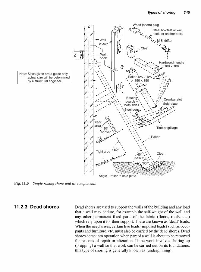
Dead shores are used to support the walls of the building and any load
that a wall may endure, for example the self-weight of the wall and
any other permanent fixed parts of the fabric (floors, roofs, etc.)
which rely upon it for their support. These are known as ‘dead’ loads.
When the need arises, certain live loads (imposed loads) such as occu-
pants and furniture, etc. must also be carried by the dead shores. Dead
shores come into operation when part of a wall is about to be removed
for reasons of repair or alteration. If the work involves shoring-up
(propping) a wall so that work can be carried out on its foundations,
this type of shoring is generally known as ‘underpinning’.
Types of shoring 345
Wallpiece
Wallhook
Cleat
Wood (seam) plug
M.S. drifter
Hardwood needle100 × 100
Leverage
Crowbar slot
Sole-plate
Timber grillage
Raker
CleatTight area
Angle – raker to sole-plate
80°
80°
45°
to 60°
90°
or over
Slackarea
Lin
e o
f rake
r
Bracingboards –
both sides
Steel dogs
Raker 125 × 125or 150 × 150
Steel holdfast or wallhook, or anchor bolts
Note: Sizes given are a guide only, actual size will be determined by a structural engineer.
Fig. 11.5 Single raking shore and its components
11.2.3 Dead shores
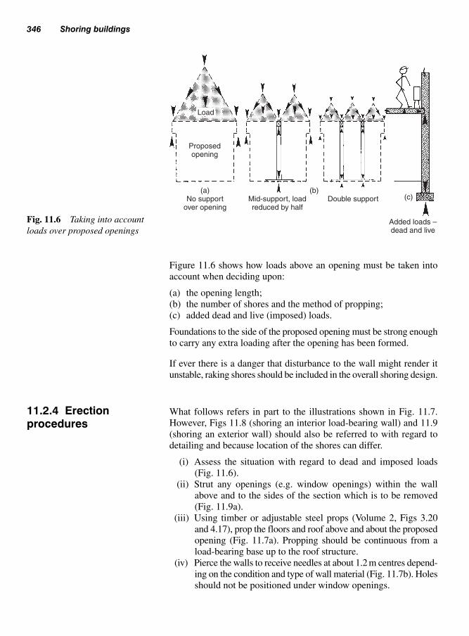
Figure 11.6 shows how loads above an opening must be taken into
account when deciding upon:
(a) the opening length;
(b) the number of shores and the method of propping;
(c) added dead and live (imposed) loads.
Foundations to the side of the proposed opening must be strong enough
to carry any extra loading after the opening has been formed.
If ever there is a danger that disturbance to the wall might render it
unstable, raking shores should be included in the overall shoring design.
What follows refers in part to the illustrations shown in Fig. 11.7.
However, Figs 11.8 (shoring an interior load-bearing wall) and 11.9
(shoring an exterior wall) should also be referred to with regard to
detailing and because location of the shores can differ.
(i) Assess the situation with regard to dead and imposed loads
(Fig. 11.6).
(ii) Strut any openings (e.g. window openings) within the wall
above and to the sides of the section which is to be removed
(Fig. 11.9a).
(iii) Using timber or adjustable steel props (Volume 2, Figs 3.20
and 4.17), prop the floors and roof above and about the proposed
opening (Fig. 11.7a). Propping should be continuous from a
load-bearing base up to the roof structure.
(iv) Pierce the walls to receive needles at about 1.2 m centres depend-
ing on the condition and type of wall material (Fig. 11.7b). Holes
should not be positioned under window openings.
346 Shoring buildings
Load
Proposedopening
(a)No support
over openingMid-support, loadreduced by half
Double support(b)
(c)
Added loads –dead and live
Fig. 11.6 Taking into account
loads over proposed openings
11.2.4 Erectionprocedures

(v) If access to the opening is to be restricted once the shores are
in position, place the new lintel (beam) – a steel universal
beam (UB) or reinforced concrete – against the foot of the wall
at this stage.
(vi) Position needles (steel or timber, Fig. 11.10) through the wall,
after making sure that when the shore is in position they are long
enough to allow a working space to one or both sides of the
existing wall (Fig. 11.7c). The material and sectional size of
the needles will determine their permitted overhang.
(vii) Position sole-plates to both sides of the wall upon a solid base.
Types of shoring 347
Windowstrutting Overhang
(workingspace)
Spacefor newlintels
Pad stone
(a) Floors shored
(b) Window strutted, needle holes pierced, and new lintel positioned nearby
(e) Shore and needles fully braced
(c) Needles and sole-plate positioned
(d) Dead shores plumbed and fixed, tightened to needles via wedges
(f) Masonry cut away to leave cogged key
(g) Piers made good and lintel in position
Note: Needles must not be positioned under windows or wall openings.
Fig. 11.7 Erection procedures for dead shoring

(viii) Position dead shores (Fig. 11.7d). Sectional size will depend on:● the type and height of the building (the number of storeys);● the length of the shore;● the distance between shores.
They should provide a stable base for the needles (see
Fig. 11.8).
After plumbing the shores, use hardwood folding wedges
(Fig. 11.9b) to tighten the needles up against the underside of
348 Shoring buildings
Adjustable steel prop(See Vol. 2, Fig. 3.20)
Interior load-bearing wall
Proposednew opening
600
Fig. 11.8 Dead shoring for an
internal load-bearing wall.
Roof
(a) StrutsWallpiece
Window strutting100 × 50
Packing Plan bracing
NeedleSteel dogTieBrace
Longitudinalbracing
Shore
TieFolding wedgesSole-plate
Newlintel
800 to900
Throughbearing runner
alternativemeans of propping
first-floor joists
Conc. floor
(b) Folding wedges
X
Foldingwedges
Adjustablesteel props
Note: Sizes to be determined by a structural engineer.
Fig. 11.9 Dead shoring for an exterior wall

the wall. Packing may be needed to ensure that the needles are
level. Wedges may be positioned at the head or foot of the shore.
Secure the joints with cleats (nail heads left to draw) and
steel dogs.
(ix) Brace the needles to the shores and longitudinally brace and tie
the shores together (Fig. 11.7e). Plan bracing (across the top of
the needles) may also be used.
(x) Check all joints inside and out for tightness.
(xi) Masonry may now be carefully removed as necessary (Fig. 11.7f).
(xii) Rebuild piers to form a bearing for the new lintel (Fig. 11.7g).
The pad stone is usually cast in concrete. Construct formwork if
an in-situ concrete lintel is to be cast (see Volume 2, Fig. 3.19).
After the lintel is installed and/or set, the masonry above is
made good.
(xiii) Leave the masonry until it is set and strong enough to sustain
the loads to be placed upon it when the shoring is removed.
(xiv) After the prescribed period of time, the shoring is ‘eased’ (by
gently slackening the folding wedges a small amount – any
settlement of the wall structure will be detected if the wedges
start to retighten) and eventually struck (dismantled). This stage
should be undertaken only on the instruction and with the super-
vision of the person responsible for the design and construction
of the shoring – usually a structural engineer.
(xv) Dismantle the shoring in reverse order to its assembly.
(xvi) If raking shores have been used to accompany the dead shores
they will be dismantled last.
Type of shoring 349
Needle
ShoreSteel dog
Stable
Twist orbuckle
Unstable
Packing
Timberblocking Packing
Head-plate
Shores
UB steelneedle
Fig. 11.10 Providing a stable
base for needles
This type of shoring (Fig. 11.1(c)) is used in situations where, for
example, an opening has been formed between buildings, which may
include a row of terraced houses. The remaining end walls therefore
must be supported to prevent distortion, which will lead to eventual
collapse. Generally, the shoring is situated high enough to allow max-
imum support and, if required, pedestrians or traffic.
Shores of this nature are specifically designed by structural engineers.
Because shoring is required to support and/or restrain a load-bearing
structure, its design is very important. In the interests of safety, there-
fore, all shoring systems should be designed by a structural engineer
(including calculations to show the loading upon all shoring load-
bearing members and the sectional sizes and spacing to support those
loads) and should be erected by persons competent to do so, under
the direction of the designer (usually a structural engineer).
Safe working platforms must be provided for operatives erecting,
servicing, and dismantling shoring – see Volume 2, Chapter 10
‘Scaffolding’. Many shoring operations will require the erection of
a hoarding as a means of offering site and public protection, see
Volume 2, Chapter 2 ‘Fences and hoarding’.
350 Shoring buildings
References
Construction (Health, Safety and Welfare Regulations) 1996.
HSE Information Sheet. General access, scaffolds and ladders –
Information sheet 49.
Heath and Safety Regulations 1977.
The Highways Act 1980.
BS 5268–5: 1989, Structural use of timber, code of practice for the
preservative treatment of structural timbers.
BS 5973: 1993, Code of practice for access and working scaffolds
and special scaffold structures in steel.
BS 1139–3: 1994, Specification for prefabricated access and working
towers.
BS 1139–4: 1982, Specification for prefabricated steel splitheads and
trestles.
BS 1129: 1990, Timber ladders, steps, trestles, and lightweight sta-
gings.
BS 2037: 1994, Aluminium ladders, steps, and trestles for the build-
ing and civil engineering industries.
BS 2482: 1981, Specification for timber scaffold boards.
BS 5973: 1993, Section 9 – tying to buildings.
11.2.5 Flying shores
11.3 Safety

During their working life, most carpenters and joiners will spend a great
deal of their time repairing and/or maintaining various items associ-
ated with buildings and their contents.
Firms that specialize in this type of work tend to employ craftsmen
who are flexible, in the sense that they are conversant with and capable
of carrying out basic jobs outside their own specialist area. For example,
a carpenter and joiner may be expected to glaze or re-glaze a window,
or use a trowel and float to do some patchwork on a plastered wall or
concrete floor. The ability to lay or renew broken tiles or slates may
also be a requirement.
A sound knowledge of building construction is essential for all skilled
operatives engaged on this type of work.
Certain items of hardware are expected to be replaced periodically,
due to wear through use; failure to provide and carry out a general
maintenance programme (for example, to ensure that the building
remains watertight and that protective coatings to woodwork are regu-
larly reapplied, etc.) will lead to deterioration and eventual failure of
many other building materials.
In these days of short-term apprenticeships, multi-skill training to a
high standard is not practicable. This, among other factors, has led to
the setting up of firms which specialize in specific areas of work, for
example timber decay due to fungal or insect attack, damp-proofing,
insulation, and replacement windows, to mention just a few.
As with any job, the way in which one organizes repair work is very
important; therefore, when called upon to survey a building with
regard to carrying out repairs, a true record should be made of its
Repairs andmaintenance
12
12.1 Generalrepairs survey

existing condition. There are four ways by which a record can be
made:
(i) a detailed list (schedule),
(ii) annotated sketches,
(iii) a combination of (i) and (ii),
(iv) camera.
Figure 12.1 and Table 12.1 have been drawn up as an example of how
a pre-war ‘back-to-back’ end terrace house could be surveyed by
352 Repairs and maintenance
Entry &exit
Dampness tochimney breast
Flight holes – purlin,staircase, floor
DN
Second floor (attic)
UP DN
DN
Door sticking
Rotten floor board
First floor
Defective bottom sash
Ground floor
Rotten window frame
Area 1
Area 2
UP
UP
Defective sash cord
Loose floorboard
Defective treads(2nd and 3rd up)
Floor springingDoor sticking
Suspect dry rot
Rotten joist ends (wet rot)
Cellar
Plasterwork – damp
Lower sash – bottom rail rotten Top sash – cracked window pane
Rotten floor boardand skirting board
3rd
2nd
1st
4th
Attic
2nd floor
1st floor
Ground floor
Bed room
Bath
room
Living room
Store
Kitchen
Store
Cellar
SL
Void
Unvented void
Survey page and suggested layout
Pictorial view of property
SL � Skylight
DN � Down
Fig. 12.1 Typical floor plan layout to show some possible defects to a pre-war back-to-back terrace house

General repairs survey 353
Table 12.1 Example of how a repairs survey on a back-to-back end terrace house could be tabulated (to beused with Fig. 12.1)
Location Defect Possible cause Remarks
1. Living room Rotten floorboard and Dry rot (unvented under- See Volume 1, Chapter 2skirting board floor space)Floor area under window Cellar rot (wet rot) – See Volume 1, Chapter 2springing confirmation in cellarExterior door sticking Over-painted; moisture See Table 12.2
movement; door sagging; defective hinge; etc.
2. Stairs to first floor Nosing split Heavy wear; timber defect; See section 12.4.9(second and third riser groove cut too deep.treads)
Squeaking steps Shrinkage due to moisture See section 12.4.9movement; treads and risers unhoused.
3. Bathroom Rotten floor board Wet rot, due to water spillage See Volume 1, under bath or leaking waste/water pipe. Chapter 2
4. Bedroom Defective door latch Worn and over-painted RenewDoor sticking Defective hinge RenewLoose floorboard Access trap to services See section 12.4.8Cracked window pane Unknown Reglaze – see section (top sash) 12.4.5Rotten bottom rail Window condensation Renew(lower sash)Damp plasterwork Surface condensation – See Volume 1, Chapter 2
penetrating damp
5. Stairs to second Flight holes in treads, Woodworm (common See Volume 1, Chapter 2floor (attic) risers and strings furniture beetle)
6. Second floor Flight holes in the purlin Woodworm (common Volume 1, Chapter 2(attic) and floorboards furniture beetle)
Gable-end window sash Defective sash cords Renew all cords – see will not open section 12.4.7Dampness to chimney Defective cement pointing, lead See Volume 1, Fig. 2.5breast step, flashing, or lead soakers;
interstitial condensation.
7. Note: On returning downstairs, recheck rooms and staircases.
8. Kitchen Window (bottom Defective haunch or wet rot Dismantle sash, insert sash) – joint of stile false tenon, possibly and bottom rail splice stile
9. Cellar(area 1) Rotten window frame Cellar rot (wet rot) See Volume 1, Chapter 2(area 2) Rotten joists ends (living Cellar rot (wet rot) See Volume 1, Chapter 2
room floor)Cellar void Dampness (see living No ventilation Provide ventilation (air
room – dry rot) bricks) to external wall –pierce interior walls

using method (iii). – Further examples may be found in Work
Activities in Section 13 by Brian Porter and Reg Rose.
The listing of external repairs is often dealt with separately – preferably
after the internal inspection. This is because defects found within the
dwelling could be the result of an exterior defect which, without close
scrutiny, might otherwise have been missed. For example, a damp patch
on the inner face of an external wall could be the result of surface
condensation, but on the other hand it could have been caused by an
excessive amount of rainwater running down the outside face wall,
due to a blocked fall pipe or a defective gutter joint.
Provisional observations from ground level can be enhanced by the
use of binoculars. Or a more detail report may need the use of some
form of scaffolding (see Vol 2, chapter 10 Scaffolding).
A survey of this nature should cover the following:
1. Face walls● Stability (any signs of structural movement – settlement
cracks) – note the close proximity of any trees.● Height of the damp proof course (DPC) above the ground
level – should not be less than 150 mm.● Air grate (air bricks) clear and away from any overgrown
vegetation.● Cement pointing – no open joints.● Cement rendering – no visible cracks or loose parts (no hol-
low sound when gently tapped).● Staining (no undue discolouration) – particularly just above
the DPC line or under the roof eaves, and behind the rain
water fall pipes.
2. Wall openings● Doors – general condition of the woodwork, and particular
attention to weather seals around the frame, threshold and
weatherboard.● Windows – general conditions of the woodwork, glass and
putty/sealant pointing – particularly weather seals around
window frames.
3. Fall pipes● Soil pipes – joints fully caulked (sealed).● Vent pipes – joints fully caulked (sealed), and extend above
any window or house vent opening at least 900 mm if less than
3 m away (as per Building Regulations).● Particular attention should be paid to the backs of cast iron
pipes, as this is usually the first place to corrode (rust) due to
lack of paint protection.
4. Gully grates● Check for signs of water being discharged over the edges into
the soil, onto the path/patio or up against the wall of the house.
354 Repairs and maintenance
Note: A similar survey for a semi-detached can be found in WorkActivities, section 13

● Check the water level in the ‘U’ bend by pouring a bucket of
water down into the gully.
5. Eaves guttering (spouting)● Falls – no signs of static water in the guttering. Test the fall of
the guttering on a dry day by pouring water into the guttering
at its highest point.● Joints – check for any water stain on the underside of the gut-
tering, and signs of any moss growth.● Vegetation growth within the gutter – due to static water or
poor falls. Check any wooden gutters for similar signs, which
may also be due to similar conditions or possible decay.
6. Eaves (pitched and flat roof)● Fascia boards (open, closed or flush eaves) – for signs of
decay and/or distortion.● Soffit boards (closed eaves) – for, the presence of any ventila-
tion grills or gaps.
7. Flat roofs● Surfaces – visible falls, signs of ponding (retained grit residue
on roof surface without solar chippings), check also for any
signs of vegetation growth.● Solar chippings – in place on built-up felt roofs.● Flashings and aprons (metals (lead) or felt) – intact and
securely fixed within their abutment wall.
8. Pitched roofs● Surfaces – check for missing, displaced or defective roof tiles
and slates. Also missing displaced or defective hip and ridge
tiles.● Verges – cement pointing to verge tiles/slates. Check the roof
finial, bargeboards and soffits for signs of decay and/or dis-
tortion, etc.● Roof lights (skylights) – glazing and water seals.● Dormer windows – as above (roof surfaces, eaves, glazing and
water seals).
9. Chimney stacks● Brickwork, blockwork, etc. – stability (no signs of structural
movement), cement pointing or rendering is intact – check for
any sooty deposits between joints, in particular at perpends
(vertical joints).● Flaunching (cement collar around the chimney pots) – intact,
check also for sooty deposits at joints with brickwork and
chimney pots.● Chimney flashings – check for missing or defective step flash-
ings and soakers (‘L’ shaped pieces of metal – usually lead),
which lap one another from the chimney back gutter to the
front apron to form a weather seal between the underside of
the stepped flashings and roof tiles/slates. The front apron can
General repairs survey 355

often be viewed from ground level. However, the back gutter
would require access to the roof.
10. House steps● Check for level and surface wear. Any cracks, mould growth
etc.● Check handrails for stability, fixing and fully intact.● Does the stair comply with current Building Regulations –
Approved Document ‘K’ in relation to pitch, rise or going,
headroom, handrails or balustrade?
11. Garden path and driveway● Surface condition – cracks, mould growth etc.● Drain inspection chamber – metal covers intact and secure.
12. Boundaries● Walls – make observations with regards to settlement and dis-
tortion (The local authority must be informed of any walls
adjacent to a public thoroughfare or highway that appears to
be in a dangerous condition).● Wooden fences and gate posts – check for any signs of decay
particularly at and around ground level and where water can
be retained, such as where rails cross over posts etc. (see
Volume 2, 2.5).● Wooden gates – check for sag (see 4.2.2), distortion (twist),
and decay, particularly at joints, junctions and where mem-
bers overlap (as above), also behind metal fixings.
13. Out-buildings (attached and/or detached)● Garages – observations as above.● Porches and conservatories – as above.
14. Dangerous materials and liquids● Make a note of any suspicious materials or liquids (foul water
etc.) that you may encounter. For example asbestos which was
once a common building material used in roofing and pipe
insulation etc. – seek advice where necessary.● Always wear the appropriate safety wear. Carry out a risk
assessment before proceeding with the site survey.
Once the site survey has been completed, you may be required to
pass on this information to a colleague via a written report. You could
also include a simple annotated line diagram of each elevation indi-
cating any defects. Include also a written schedule similar to Table
12.1 and any photographs of particular areas showing defects areas
from the survey.
Most items of repair work are done while the building’s occupants
are in residence. The occupants should be inconvenienced as little as
possible, and care must be taken to minimize damage to decorations
356 Repairs and maintenance
12.2 Customerrelations

and not to damage furniture in any way. Exterior work may involve
working from or over a cultivated garden. Landscaping and planting-up
of even a small garden can run to many hundreds, if not thousands, of
pounds – therefore care must be exercised both inside and outside the
building as necessary.
Occupants should receive prior notice of the nature and timing of the
work proposed (time span will depend on the type and amount of work
to be done) well before work begins to allow them time to prepare the
site as necessary. Most firms are expected to provide dust-sheets and
assistance in moving heavy furniture, lifting carpets, etc.
Operatives employed to carry out small interior repair or maintenance
work within a fully furnished home should be prepared to wear the
appropriate footwear.
Gardens should be treated with similar respect – a lawn could take
years to recover from damage caused by the foot of a ladder, etc.
Exterior finishes to house walls can easily be damaged by rearing or
running ladders, etc. up against them. If the wall surface is liable to
become marked or damaged, consider wrapping the top of the ladder.
Never allow anything to be dropped to the ground, be it from a scaffold
roof or through a window. The risk of injuring a passer-by or by-
stander may be obvious, but the possible damage to the object and its
landing place are not always apparent.
Finally, one cannot emphasise enough that from the outset of the job
that a little care and consideration can go a long way towards good
customer relations, which will not only provide you and your com-
pany, but will also add credits to your competence as a skilled capa-
ble operative.
Once an item of woodwork has been installed, fixed, and possibly
serviced by other trades, its removal or repair and eventual reinstate-
ment may require the use of tools and equipment outside the normal
list generally prescribed for a bench-hand or a building-site worker.
In fact many of the tools found in a maintenance joiner’s toolbox or
bass (basin-shaped stout hessian holdall) would normally be found in
tool kits used by an engineer or bricklayer.
Listed below are examples of the types of hand and power tools
required (see also Volume 1, Chapters 5 and 6), including equipment
often needed. Items marked * may be carried in a Joiners bass.
Quality and sharp tools should always be protected. The main reason
for using a bass is that it is easy and light to carry, and tools are
Hand/power tools and equipment 357
12.3 Hand/powertools andequipment

instantly accessible. The main disadvantage is that unprotected tools
can easily become damaged by the constant knocking of one against
another. Items such as sharp chisels may protected by plastic caps or
masking tape.
(a) Measuring, setting-out, and marking tools
(i) 1m folding rule;
(ii) 3 m steel tape measure;
(iii) 1 m spirit level;
(iv) 300 mm spirit level (or boat level)*;
(v) Builder’s line (chalk line)*;
(vi) Plumb bob*;
(vii) Combination square*;
(viii) Marking gauge*;
(ix) Sliding bevel*.
(b) Saws
(i) Panel saw*;
(ii) Tenon saw (short-bladed)*;
(iii) Bushman-type tubular-steel frame saw;
(iv) Flooring saw;
(v) Pad saw*;
(vi) Hacksaws – large and junior*;
(vii) Coping saw*;
(viii) Jig saw;
(ix) Reciprocating saw;
(x) Circular saw.
(c) Planes
(i) Jack plane (wooden types are often preferred to metal, because
they are lighter and less likely to break);
(ii) Smoothing plane (metal)*;
(iii) Rebate plane*;
(iv) Block plane*;
(v) ‘Surform’ types (planes and files)*;
(vi) Planer (see Volume 1, Chapters 6 and 7 for safe use of power tools).
(d) Boring tools
(i) Carpenter’s brace and an assortment of bits, including a coun-
tersink, and a turnscrew*. Drill bits with tapered square shanks
(morse drills) and an expanding-bit set should be included.
Loose bits should be kept in a stout bit roll; (Vol. 1, Chapter 5)
(ii) Hand drill (wheel-brace), with a boxed set of twist drills*;
(iii) Set of bradawls*;
(iv) Drill/screwdriver (see Volume 1, Chapters 6 and 7 for safe use
of power tools).
358 Repairs and maintenance
}}
Saw teeth must
be protected with
a sheath if saws
are to be carried
in a bass. (Vol. 1,
Chapter 5)
See Volume 1, Chapters 6 and 7
for safe use of power tools

(e) Chisels*
An assortment of:
(i) Bevel-edge chisels;
(ii) Firmer chisels;
(iii) Registered chisels;
(iv) Gouges;
(v) Engineer’s cold chisel – for cutting steel and masonry*;
(vi) Mason’s chisels – for plugging (seaming chisel and star-drill
chisels) and cutting (bolsters)*;
(vii) Flooring chisel (tonguing tool)*.
All loose chisels must be kept within a stout chisel roll. (Vol. 1,
Chapter 5)
(f) Axe or blocker*
The blade must be protected with a thick, strong, leather or similar
sheath.
(g) Hammers
(i) Engineer’s hammer*;
(ii) Club or lump hammer;
(iii) Warrington hammer (number 2)*;
(iv) Claw hammer*;
(v) Nail and staple gun (see Volume 1, Chapters 6 and 7 for safe use
of power tools).
(h) Sanders
(i) Belt;
(ii) Orbital sheet heavy duty
(iii) Random orbital ‘Palm’ grip
( iv) Detail sander.
(i) Screwdrivers
(i) Rigid-blade types – large and small (electrician’s) slotted and
Pozidriv*;
(ii) Ratchet*;
(iii) Spiral ratchet, with an assortment of bits and drill points;
(iv) Turnscrew (for use with a carpenter’s brace)*;
(v) Power screwdriver (see Volume 1, Chapters 6 and 7 for safe
use of power tools).
(j) Pincers and pliers*
(k) Adjustable spanner*
(l) Punches
Nail punches, centre punch, and drifts*.
Hand/power tools and equipment 359
} (see Volume 1, Chapters 6 and
7 for safe use of power tools);

360 Repairs and maintenance
(m) Metal files
(i) Mill saw file (with a wood/plastics handle) or a ‘Farmer’s
friend’ file with a metal handle*;
(ii) Saw file;
(iii) Warding file*;
(iv) Needle files (set).
(n) Knifes
(i) Pocket knife;
(ii) Trimming knife*;
(iii) Cobbler’s hacking knife – for removing hard dried putty point-
ing (fronting) and bedding from glazed window rebates*;
(iv) Putty pointing knife*.
(o) Trowels
(i) Bricklayer’s pointing trowel*;
(ii) Mastic pointing trowel*;
(iii) Plasterer’s float.
(p) Ancillary equipment
(i) Dust-brush (painter’s)*;
(ii) Oilstone (combination stone in box)*; (an assortment of
sharpening stones are available)*;
(iii) Oil can
(iv) Cork block and abrasive papers*;
(v) Wrecking bar (tommy bar);
(vi) ‘G’ cramps (minimum two);
(vii) Saw stool or ‘Workmate’; (or similar)
(viii) Nail and screw box;
(ix) Nail and screw bag (circle of stout fabric with draw-string)
for use with a bass – filled with assorted types and sizes*;
(see Vol. 1, Chapter 5)
(x) Window-cord box – containing a ‘mouse’, pulley pegs
(pointed dowel), sash nails (tacks), and 38 mm oval nails;
(xi) Panel-pin tin (box), assorted sizes*;
(xii) Joiner’s bass (note: a plumber’s bass is smaller); (see Vol. 1,
Chapter 5)
(xiii) Toolbox;
(xiv) Nail and screw pouch;
(xv) Tool-belt and holsters;
(xvi) Plasterers hand-board (hawk);
(xvii) Mastic gun with assortment of cartridges;
(xviii) Dustsheets (fabric or plastic);
(xix) Box of plastic plugs (assorted sizes).
(q) Personal Protective Equipment (P.P.E.)
(i) Respiratory protection
There a number of different types of protective masks avail-
able, each suited for various working situations. For example
working with:

Hand/power tools and equipment 361
● Clay products, hay, pollen, iron products● MDF dust;● Mist and fumes;● Organic vapours, fine toxic dust and fibres and aqueous mists;● Solid and liquid aerosol variants including brick and wood
dust, concrete plaster and sandstone;● Water based mists.
(ii) Ear defenders
These need to be comfortable as they may be worn for long
periods of time. Various types include:● Banded ear plugs;● Ear plugs;● Electronic ear-defenders;● Foam ear plugs;● Large foam-filled cups and adjustable headband.
(iii) Goggles/Specs/Full mask
Need to be impact resistant, anti-mist and allow the operative
maximum visibility. Various types are available for protection
against:● Bright light that may damage eyes, i.e. welding;● Grinding particles, sanding dust and pressure washing;● Liquid droplets and molten metals.
(iv) Head protection (Safety helmet, Hard hat)
Provides protection to the head against falling or stationary
objects. Made from high density polythene. Some types include
ear and visor protection in one. Check the life span of the hard
hat or bump cap and replace when necessary. Types include:● Bump cap;● Hard hat.
(v) High visibility clothing
A highly reflective material, which allows the operative to be
seen whilst working in dangerous situations. Must be water proof
and hardwearing. Available as:● A jacket;● Loose bands;● Trousers;● Waistcoat.
(vi) Knee protection
Protection of the knees is important, particularly when work-
ing on a hard, wet or uneven surface. Various types include:● Anti-slip, no-mark knee pads;● Gel swivel knee pads – in situations of continuous turning;● Knee pads – general use;● Kneeling mat;● Safety trousers with protective knee pads.

362 Repairs and maintenance
(vii) Protective gloves (Safety gloves)
Various types are available which can be made of cowhide,
latex and other synthetic materials, or a knitted material with
various coatings. Depending on their use, they need to be hard
wearing, heat, tear and puncture resistant. Some types may have
extra padding on the palms and fingers and may include finger
grips. Other types are disposable after one use. Protective gloves
are used for protection against:● Abrasions;● Chemicals - acids and caustic corrosive chemicals;● Cuts;● Heat;● Splinters.
(viii) Protective footwear (Safety boots)
There are many situations where the foot may be damaged by
hard surfaces, heavy objects, protruding nails or chemical
spillage. Footwear may include metal toe guards and/or sole
protectors against penetrating items such as nails or other sharp
objects. They may also be coated to resist corrosive liquids.
Types include:● Boots;● Disposable over shoes;● Shoes;● Sports trainer boots;● Trainers;● Wellington boots.
Note: Under the Health and Safety Act 1974, all P.P.E. must be
provided by the employer and worn where necessary.
(r) Testing equipment
Various testing equipment may be used before any work com-
mences i.e. location of services, and studwork checking a mate-
rial for moisture content etc. These include:● Moisture meter (see Volume 1, 1.7.1);● Stud locator (see Fig. 8.43);● Pipe/metal locator (see Fig. 8.43);● P.A.T. (Portable Appliance Test) unit.
Any items of woodwork – structural or non-structural – could at
some time be liable to damage or deterioration. Maintenance joiners
should therefore be prepared to tackle almost any type of job – the
following are just a few of the items that could be encountered.
12.4 Remedialtreatment
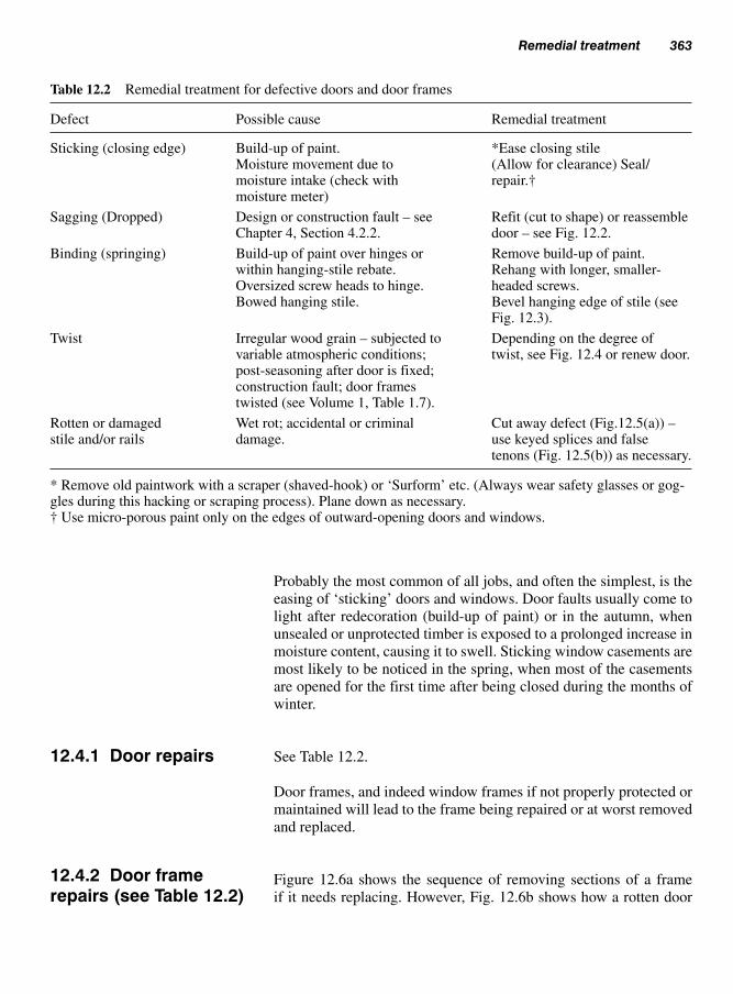
Probably the most common of all jobs, and often the simplest, is the
easing of ‘sticking’ doors and windows. Door faults usually come to
light after redecoration (build-up of paint) or in the autumn, when
unsealed or unprotected timber is exposed to a prolonged increase in
moisture content, causing it to swell. Sticking window casements are
most likely to be noticed in the spring, when most of the casements
are opened for the first time after being closed during the months of
winter.
See Table 12.2.
Door frames, and indeed window frames if not properly protected or
maintained will lead to the frame being repaired or at worst removed
and replaced.
Figure 12.6a shows the sequence of removing sections of a frame
if it needs replacing. However, Fig. 12.6b shows how a rotten door
Remedial treatment 363
Table 12.2 Remedial treatment for defective doors and door frames
Defect Possible cause Remedial treatment
Sticking (closing edge) Build-up of paint. *Ease closing stileMoisture movement due to (Allow for clearance) Seal/moisture intake (check with repair.†moisture meter)
Sagging (Dropped) Design or construction fault – see Refit (cut to shape) or reassemble Chapter 4, Section 4.2.2. door – see Fig. 12.2.
Binding (springing) Build-up of paint over hinges or Remove build-up of paint.within hanging-stile rebate. Rehang with longer, smaller-Oversized screw heads to hinge. headed screws.Bowed hanging stile. Bevel hanging edge of stile (see
Fig. 12.3).
Twist Irregular wood grain – subjected to Depending on the degree of variable atmospheric conditions; twist, see Fig. 12.4 or renew door.post-seasoning after door is fixed; construction fault; door frames twisted (see Volume 1, Table 1.7).
Rotten or damaged Wet rot; accidental or criminal Cut away defect (Fig.12.5(a)) – stile and/or rails damage. use keyed splices and false
tenons (Fig. 12.5(b)) as necessary.
* Remove old paintwork with a scraper (shaved-hook) or ‘Surform’ etc. (Always wear safety glasses or gog-gles during this hacking or scraping process). Plane down as necessary.† Use micro-porous paint only on the edges of outward-opening doors and windows.
12.4.1 Door repairs
12.4.2 Door framerepairs (see Table 12.2)

364 Repairs and maintenance
Add weather-board
Panelled doorBattened door
Opened joints
Remove top bevel, lift door,add weather-board to cover gap
Dismantle and reassemble, orcorner-to-corner cramp then face
one or both sides with suitablemanufactured board (e.g. plywood)
Remove
New hinge
positions
Fig. 12.2 Sagging doors
Protrudingscrew heads Hinge being sprained
Gap
Check clearance
Bowed stilebinding on rebate
Build-up ofpaint (cushion)
Fig. 12.3 Hinge-bound doors
Add stop laths,or ease rebate,
or bothFig. 12.4 Possible remedy for
slightly twisted doors

Remedial treatment 365
frame (usually wet rot or damaged jamb foot) can be repaired by
splicing.
● Make 45° cuts sloping down towards the exterior – in this way,
water is shed away from the joint (Fig. 12.6b(i)).● Remove the defective portion. Expose and clean out the anchor
peg hole (Fig. 12.6b(ii)). Use a sharp chisel to chop away waste
when forming the scarf.
45° cut
(a)
Keyedsplice
Defective doorstile and jamb
(damage or rot) Falsetenon
Splice
Peg/dowel
(b)
Fig. 12.5 Repairing a damaged
door
Saw cuts
Jamb saw cuts
1
3
2
5
4
Saw cuts
Saw cuts
Jambs – extra cutsmay be needed
2
1
x
3 4
Head
Sill
Open door frame Closed door/window frame
� Numbered sequence for removal from opening
Fig. 12.6a Removing door/win-
dow frames from their openings

● Cut a replacement piece out of material with the same or similar
(oversize) section (Fig. 12.6b(iii)), or use squared unrebated sec-
tion – the profile can be marked off the existing one after the joint
has been fixed.● Bore holes for the anchor peg and fixing screws (see Fig. 4.45).
Treat all end grain and the back with wood preservative and –
when dry – paint them.
366 Repairs and maintenance
Fig. 12.6b Splicing a damaged door jamb
Decay or defect
45° kerfsmin. 200 mm
Dowel holein concrete
Scarfedsplice
Splicecomplete
(i) (ii) (iii) (iv)
Holdfast
Steel drifter
Lath to cover headof holdfast
Screwdriver
Seaming chiselFoot of jamb loose
Wood wedge
(See Vol. 1, Fig. 12.15)
Modern methodusing frame fixing
(see Figs. 3.33 and 3.34)
(a) Traditional method of fixing (b) Modern method of fixing using ‘frame-fixings’
Fig. 12.7 Refixing a loose door frame

Remedial treatment 367
● Place cement grout (sand and cement mix) around the peg hole.
Coat the splice joint with waterproof mastic before tightening it
by leverage from the floor and screw through the splice.● Dress the joint with smoothing and rebate planes and make good
the cement work around the base (Fig. 12.6b(iv)).
12.4.2.1 Loose door frames/jambs
These were originally secured back to the wall using steel hold-fasts
as shown in Fig. 12.7a. These would be fixed to the face of the jamp
and concealed with a cover lath.
However, ‘frame fixings’ (Fig. 12.7b), are now used as a modern alter-
native and, depending on the situation, a number of different varieties
are available.
See Table 12.3.12.4.3 Sash repairs
Table 12.3 Remedial treatment for defective sashes
Defect Possible cause Remedial treatment
Sticking As doors (Table 12.2). As doors (Table 12.2).
Sagging Defective or worn hinge(s). Renew hinge(s).Inadequate or defective Re-glaze and reposition setting or locating glazing glazing blocks as shown blocks. in Fig. 3.47.Defective corner – rotten Repair* or remake sash.or damaged.
Binding As doors. As doors.(springing)
Twisted Construction fault; twisted Small amounts may be frame. taken up by stays and
fasteners – see also Fig. 12.4.
Rotten or Wet rot – see Volume 1, Opening sashes should damaged Chapter 2. be remade. Fixed sashes members could be repaired
(spliced and false tenoned) – see Fig. 12.5.
Broken Sash sticking; accidental, See Section 12.4.5 glass or criminal damage. Re-glazing a window.
* Steel mending plates (angle plates) should only be used as a temporary measure

368 Repairs and maintenance
Condensation
Shrinkage dueto differentialmovement ofcomponents
Shrinkage gap – hardenedputty breaks and becomes
displaced – moisture retained
Areas subject todecay due to wet rot
Moisture retaineddue to capillarity(via narrow gap)
Fig. 12.8 Decay as a result of
permanent moisture presence
Wood pellet
Try not to cutback beyond
this line
Splice
Sill
Sill
Fig. 12.9 Repairing a damaged
or rotten sill
The sill and the bottom of jambs and mullions are the most likely
places in which to find rot. Jambs and mullions can be dealt with in
the same way as door jambs (Fig. 12.7). However, a word of warning –
if the jambs or mullions form part of a bay window, it is highly likely
that they have been used as loadbearing members to the floor or (more
likely) the roof above in which case, before they are disturbed, all
dead and imposed (live) loads bearing on the members must be suit-
ably and safely supported (see Chapter 11). Defective load-bearing
members should not be spliced but should be replaced as a whole.
Window sills can present problems, especially if the defects extend
from outside to beyond the front line of the sash. In this case it would
be advisable to replace the whole window (for example, see Volume 1,
Fig. 2.10). Figure 12.9 shows how the nosing of a sill can be spliced.
12.4.4 Window framerepairs
Note: The removal of windowframes is similar as for doorframes. See Fig. 12.6a

Work on large window panes should only be undertaken by special-
ist glaziers who are equipped for such work.
Where practicable, an opening light should be unscrewed from its
frame and broken glass removed safely at ground level. However,
broken glass within a fixed light must be treated with extra caution –
operatives should at all times position themselves at a safe distance
above and away from the window, in case any broken pieces of glass
become dislodged during the work. The area below the window must
be cordoned off with adequate warning signs displayed to ensure that
no one enters this potential danger zone.
Before any work begins, operatives must be wearing either safety
glasses or goggles, which must remain in position during the whole
operation as protection from glass splinters which will inevitably be
shed in varying degrees while the broken glass pane is being removed.
Stout leather gauntlet-type gloves with rubber finger-grips should be
worn to protect hands and wrists while handling glass – particularly
when removing broken pieces.
Starting at the head or top rail, work around the frame or sash remov-
ing old putty fronting (pointing) with a ‘hacking knife’ and hammer.
After all the edges of the glass within the rebate have been exposed,
remove any glazing sprigs (or panel pins) with pliers; then, using an
old wide wood chisel held flat against the glass, gently tap the putty
bedding with its blade as shown in Fig. 12.10. This action will dis-
lodge the broken glass pieces from the rebate.
Repeat as necessary. Detached sashes can be laid flat on the ground
during the latter part of this process. When all the broken pieces have
been removed, old putty back bedding should be hacked away
to leave a clean rebate that should then be painted (sealed) before
re-glazing.
Before any glass is replaced or newly installed, consideration must be
given to areas known as ‘critical’ glazed areas (see Chapter 4, section
4.6.6) and the use of safety glass (toughened glass). These are situ-
ations where there is a possible danger of breakage not only acciden-
tally, but also by potential intruders.
Methods of glazing the window are explained in Chapter 3,
section 3.8.
If the glass is ‘beaded’-in, the operation as a whole is made easier,
but beware of displacing pieces of glass when removing beads.
Remedial treatment 369
Note: Any form of glazed areas canbe a potential safety hazardwhether installing or removingglass if not carried out correctly –using risk assessment procedures
12.4.5 Re-glazing awindow
12.4.6 Removing thebroken glass pane

It is false economy not to renew all four cords if one sash cord breaks.
There are many schools of thought as to how this operation should be
carried out, but the method below will prove to be both quick and
effective. All work is carried out from inside the dwelling, therefore
the surrounding floor area should be protected. If a dust-sheet is used
for this purpose, it should not be placed on a polished floor where you
might stand or walk, as it will very likely slip from under you.
The following should be read in-conjunction with Fig. 12.11.
(i) Close and securely fasten the sashes to prevent sliding or
falling over when beading is removed.
(ii) Cut any remaining cords to the lowered sash and gently lower
the sash weight to the bottom of the case. (Never allow a
weight to drop under its own weight, as this could damage the
case and its fixing.)
(iii) Leaving the head and sill staff beads in place, remove the right-
and left-hand staff beads (Fig. 3.18) by first using a sharp trim-
ming knife to cut through any layers of paint covering the joint,
then (after removing any screws) easing the beads out from the
centre by using an old wide wood chisel or flooring chisel (see
Fig. 12.12a) until they are bow-shaped and can be disengaged
from their corner mitres. Nails should be pulled through the
beads with pincers to avoid damaging the paint film. (Round-
headed nails should not have been used but, if they have been,
cut off the protruding portion with a junior hacksaw). The beads
should then be laid at their respective sides of the window after
marking (T) at their top ends.
(iv) Unfasten the lower sash. Lift it out of the window, remove old
cord and nails from the stiles, and put it to one side.
(v) Unfasten and lower the top sash and cut its cords as at stage (ii).
370 Repairs and maintenance
Stout (strong) leathergauntlet-type industrial
gloves (finger-grips)
Slide (gently tap)
Old wide wood chisel
Broken glass
Board or flat base supportFig. 12.10 Dislodging broken
glass from its framework
12.4.7 Renewing sashcords

Remedial treatment 371
(vi) Holding the sash steady to prevent it falling, remove the part-
ing beads (after cutting through any paintwork as previously
described) by starting at the sill end and easing them out of
their grooves with a chisel. They may or may not be nailed – if
they are, remove with care.
(vii) Lift out the top sash, remove old cords and nails from the
stiles, and put it to one side.
(viii) Remove the pockets (one screw each side, Fig. 3.20) and take
out the weights from their cases. Each weight should have its
old cord removed and be chalk-marked ‘F’ (front) or ‘B’ (back),
then laid on the floor at its appropriate side of the window.
(ix) Mark line (sash-cord) lengths as shown in Fig. 12.11a.
Suitable distances X and Y, to allow for cord fixing and pulley
clearance (Fig. 12.11e), are marked with chalk on the stiles of
both sashes. These distances are then transferred to the face of
the pulley stiles.
(x) Figure 12.11b shows how a cording ‘mouse’ can be made from
either small ‘rolled’ lead sheet or a short length of sash chain
(sometimes used on heavy sashes in place of cord). The mouse
string (not less than 2 m long) is attached to the end of a ‘knot’
(hank) of good-quality waxed or recommended alternative sash
cord as shown, and the mouse is made ready to be threaded
over the pulley wheel. (Ensure that the pulley wheel is freely
running and not broken – lubricate or replace as necessary.)
(xi) Figure 12.11c shows two alternative methods of cording the
window. At the end of the run, the cord is attached to the
appropriate back top sash weight (TSW) (see Fig. 3.23).
(xii) Working from the right-hand or left-hand side (depending on
the method of cording), feed the corded weight for the top sash
into the box (Fig. 12.11c). With the weight resting in the verti-
cal position off the box bottom (making sure it is on the correct
side of the parting slip, (Fig. 3.19) pull the weight up to just
below the pulley and wedge the cord with a dowel peg. Then
pulling the cord down the pulley stile, cut it off 50 mm above
the chalk line X. Tie the bottom-sash weight (BSW) to the loose
cut end of the cord, pull it up to the pulley and wedge it in that
position, then cut the cord 30 mm below the chalk line Y.
Repeat these processes on the opposite side. Fix the pockets
back into position.
(xiii) Attach the cords to the sashes either by nailing with sash nails
or by knotting, as shown in Fig. 12.11e (see also 3.23). Use at
least four nails per stile – each nail should be slightly sloping
away from the rebate to avoid touching the glass. Nails should
not interfere with the pulley. Cord the top sash first, then
release its pulley wedges and reposition the parting beads.
Then cord the bottom sash. Replace the staff beads – if nails
are to be used (screws in cups are preferred), use ovals.
(xiv) When the window is re-corded in this way, it should be noticed
from Fig. 12.11f that when the top sash is closed its weights
Note: Front and back weights maydiffer in size and/or weight
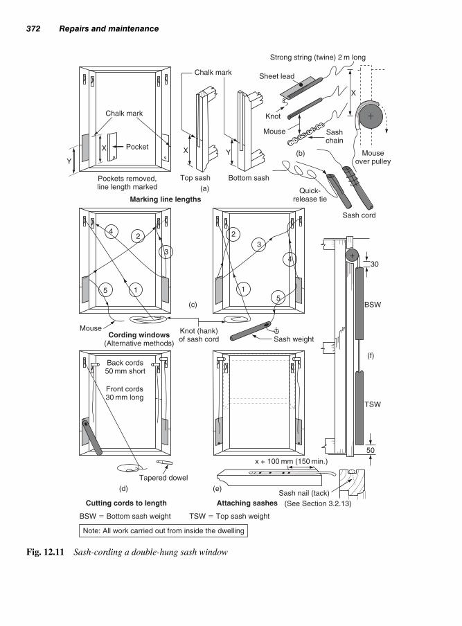
372 Repairs and maintenance
Chalk mark
Y
X
Pockets removed,line length marked
Marking line lengths
(a)
42
3
15
MouseCording windows
(Alternative methods)
Back cords50 mm short
Front cords30 mm long
Tapered dowel
(d)
Cutting cords to length
BSW � Bottom sash weight TSW � Top sash weight
Chalk mark
YX
Strong string (twine) 2 m long
Sheet lead
Knot
Mouse
(b)
Sashchain
X
Mouseover pulley
Top sash Bottom sash
Quick-release tie
Sash cord
30
2
3
4
15
(c)
Knot (hank)of sash cord Sash weight
BSW
(f)
TSW
50
x + 100 mm (150 min.)
(e)Sash nail (tack)
(See Section 3.2.13)Attaching sashes
Note: All work carried out from inside the dwelling
Fig. 12.11 Sash-cording a double-hung sash window

Remedial treatment 373
will be suspended 50 mm above the sill, thus allowing for any
stretch in the cords, or build-up of mortar dust, etc., in the case
bottom which could possibly interfere with the distance the
weight can travel to allow the sash to close properly. The bot-
tom-sash weights should be a minimum of 30 mm below the
pulley when the bottom sash is closed. Ensure that the sashes
run freely – rubbing candle wax over the sliding parts of the
sash can ease their movement.
(xv) Remove dust from the sill and window board with a dust
brush. Collect up spent nails and old sash cord, together with
the dust sheets, and remove them from site.
As mentioned in Table 12.1, the defect may be due to decay (rot).
However, if it is due to damage caused by carelessness in forming an
under-floor access trap (Fig. 12.12a), the two solutions are shown in
Fig. 12.12(b) and (c): either simply replace the damaged board and
provide bearings and joint cover as necessary or – if the damage cov-
ers more than one board – extend the repair or trap.
Warning: if a board has to be cut out of the floor and its underside is
not visible, there is always the possibility that services, i.e. electric
cables or water and gas pipes, may run beneath it. First switch off the
mains electricity supply to the premises or check with adequate elec-
tric metal detector – it is better to be safe than sorry! – and proceed
with caution.
Figure 12.12d shows how board ends can be cross cut. Damaged boards
can be chopped out on to a joist, using a chisel, or cut alongside.
A jig saw is useful here, but only if the underside of the board is vis-
ible and clear of services. Alternatively, a series of small holes can be
bored to help the point of a flooring saw or tenon saw to get started
on piercing the board.
A pad saw can then be used to lengthen the cut and detect any pipe-
work. (Flooring saws may differ in shape but are all designed to start
a cut from off the surface of a board and to cut into corners. They are
a most useful addition to the tool kit.)
A similar procedure can be used to rip down the tongue of a laid board.
Equally useful is a small portable circular saw set so that its blade cuts
the tongue but does not protrude below the underside of the board.
To remove or lift a board, find a suitable end joint and cross cut the other
end of the length to be removed. Rip down one tongue if the tongue-
and-groove joints between the boards are wide, or both tongues if close.
Punch the nails to at least two-thirds of the board’s depth. Using
two wide flooring chisels (sometimes called ‘tonguing tools’ – not brick
layer’s bolsters), lever the board up from one edge.
12.4.8 Repairingfloorboards

Creaking treads and damaged nosings are among the most common
faults associated with stairs. Access to the whole of a tread-and-riser
staircase is usually not possible, due to its underside (soffit) having
been plastered over.
374 Repairs and maintenance
(a)Access trap
Bearer fixed toside of joist
Joist
Damage
Flooring chisel causes damageto tongue and groove
Hole for servicesUnder-groove
removed
Bearer
EasedcornerJoint cover lath
Joist Joist
(b)
Renewing damaged board
Services (c)
Extending access trap
(d)
Caution: Services often run along joists as well as through them
Known safeareas – jig sawmay be used
Series of holesprovides start for saw
Note: New boards should be screwed, not nailed
Defective board
Jig
saw
Pre-cut slot throughtongue and groove
Fig. 12.12 Renewing damaged floorboards
12.4.9 Repairing stairs

A creaking tread is generally the result of the parting of the joint
between the riser and tread (Fig. 12.13a). This can usually be rem-
edied by gluing and screwing the tread on to the riser as shown in Fig.
12.13b. (If the treads are covered with carpet, the countersunk screw
heads will not be visible; otherwise, wood pellets can be used over
the screw heads.)
If this method does not work, then access to the underside of the
treads will be necessary to check on glue-blocking, string housing,
and mid-carriage support (if used). Adding steel brackets might be a
possible remedy.
A defective nosing can be repaired by carefully cutting away the
damaged portion and splicing on a new one (Fig. 12.13c). If possible,
do not cut back beyond the riser face. Cut the splice end at 45° (avoid
Remedial treatment 375
Tread
Gap
(a) (b)
Riser
String
Mark shape of nosing
Tread (defective nosing)
Sawkerfs
Chisel
Tread
Splice
(c)
Fit squared section
Tread
(d)
(e)Glue and screw in position – pellet and shape
Defect chiselled away
Front elevation
Plan
Plan
Plan
Note: All splicings etc, should be screwed as well as glued – screws not only hold the joint, but also serve as cramps.
Fig. 12.13 Surface repairs to a
close-string stair

the walking line 300 mm in from either side) to lengthen the joint
glue line. Fit the new rectangular section, then mark and shape the
nosing profile (Fig. 12.13d). Glue and screw the new section into
position, plug the screw-head holes with pellets, and sand to the fin-
ished shape (Fig. 12.13e). If a scotia or similar mould has been used
between the underside of the nosing and the riser, renew the whole
length – glue and pin it into position.
The working mechanism of locks, fasteners, bolts, etc. should be
kept free from paint, etc. and be lubricated to ensure trouble-free use.
(A dry graphite lubricant should be used for locks.)
Items of hardware found to be defective through wear should be replaced
with their nearest alternative. It is possible, however, that the position of
the new fixing holes, etc. will differ from the original ones, in which case
the old screw holes can be plugged with glued wood dowel or wood
filler. Unused holes (spindle holes, keyholes, etc.) and recesses should
be concealed with a filling of wood as shown in Figs 12.14a–f.
The filling piece is cut first, with slightly tapered edges to self-tighten
when fitting, placed on the timber and marked around the edges with
a sharp knife before carefully chiselling out. Alternatively, to dis-
guise a repair in timbers that are to receive a polish or varnish finish,
a diamond shaped filling piece, of similar timber, may be used (as
shown in Fig. 12.14(e) and 12.14(f)) which matches the grain and
colour of the existing timber.
The lock keep will similarly have to be filled, as shown in Fig.
12.14(g) and (h).
Making good small areas of brickwork, plasterwork and wall and
floor tiles can be found in Work Activities Section 13.5.3–5 by Brian
Porter and Reg Rose.
Before any work is carried out, particularly on older buildings, those
responsible for the building must inform those people concerned of
the location of any suspicious materials. Furthermore, a risk assess-
ment must be undertaken to identify any dangerous situations includ-
ing the following:
(a) Use of scaffolding (see Volume 2, Chapter 10);
(b) Unsafe building (see Chapter 11, shoring);
(c) Welfare of operatives and general public (see Volume 2, Chapter
2, fencing and hoardings);
376 Repairs and maintenance
12.5 Door andwindow hardware
12.6 Makinggood repairedareas
12.7 Health andsafety

Health and safety 377
Fig. 12.14 Making-good holes
and recesses
(a) Old rim lock – holes and recesses to be filled
(b) Holes and recesses enlarged to receive filling pieces
(c) Overthick filling piece glued and pinned in place
(d) Dressed flush with smoothing plane, fill nail holes and small gaps with wood filler – sand smooth
(e) Alternative method using diamond shaped filling piece glued and pinned in place (for polished timber to disguise repair)
(f) Dressed flush with smoothing plane, fill nail holes and small gaps with wood filler – sand smooth
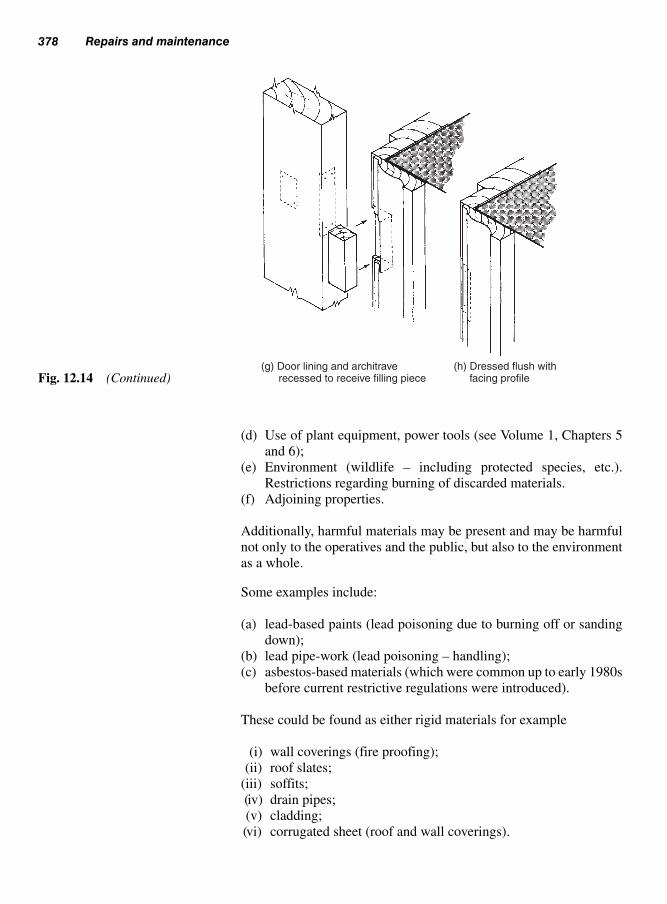
(d) Use of plant equipment, power tools (see Volume 1, Chapters 5
and 6);
(e) Environment (wildlife – including protected species, etc.).
Restrictions regarding burning of discarded materials.
(f) Adjoining properties.
Additionally, harmful materials may be present and may be harmful
not only to the operatives and the public, but also to the environment
as a whole.
Some examples include:
(a) lead-based paints (lead poisoning due to burning off or sanding
down);
(b) lead pipe-work (lead poisoning – handling);
(c) asbestos-based materials (which were common up to early 1980s
before current restrictive regulations were introduced).
These could be found as either rigid materials for example
(i) wall coverings (fire proofing);
(ii) roof slates;
(iii) soffits;
(iv) drain pipes;
(v) cladding;
(vi) corrugated sheet (roof and wall coverings).
378 Repairs and maintenance
(g) Door lining and architrave recessed to receive filling piece
(h) Dressed flush with facing profileFig. 12.14 (Continued)

Health and safety 379
References
Health and Safety at Work Act (HSAWA) 1974.
Control of Substances Hazardous to Health Act (COSHH) 1994.
The Construction (Health, Safety and Welfare Regulations) 1996.
Building Regulation Approved Document N: 2000 Glazing – safety in
relation to impact, opening and workmanship:
HSE (Health & Safety Executive) Safety leaflet ‘Working with
asbestos’.
HSE (1995) Asbestos alert for building Maintenance, repair and refur
bishment workers be awareof asbestos the hidden killet. Pocket card
INDG 188.
HSE Information Sheet General Access, Scaffolds and Ladders,
Information Sheet 49.
BS 8417: 2003, Preservation of timber – recommendations.
BS 5973: 1993, Code of practice for access and working scaffolds and
special scaffold structures in steel.
BS 1139–3: 1994, Specification for prefabricated access and working
towers.
BS 1139–4: 1982, Specification for prefabricated steel splitheads and
trestles.
BS 1129: 1990, Timber ladders, steps, tretles, and lightweight stagings.
BS 2037: 1994, Aluminium ladders, steps, and trestles for the building
and civil engineering industries.
BS 2482: 1981, Specification for timber scaffold boards.
BS 5973: 1993, Section 9–tying to buildings.
or semi-rigid materials such as
(i) caulking (flexible jointing material used for sealing);
(ii) artexing (walls and ceilings) – since 1986 now contain asbestos
substitutes. However, always check before work is carried out;
(iii) insulation.
In the case of (c) asbestos based materials or suspitious materials
these must be reported, i.e. to the Health and Safety Executive repre-
sentative, and the area sealed off before any work is carried out. If
identified as dangerous, a specialist company must be employed to
remove any material of this kind before work commences.
Note: Suitable protective clothingmust be worn at all times duringgeneral maintenance work even ifthere is only a slight suspicion of any dangerous materials (seesection 12.3q)

This page intentionally left blank

Volumes andChaptersChapter Volume 1 (3rd Edition)
1 Timber
2 Enemies of wood & wood based products
3 Wood preservatives & protection
4 Manufactured boards & panel products
5 Handtools & workshop procedures
6 Portable electric mains powered hand tools & machines
7 Battery-operated (cordless) hand tools
8 Cartridge operated fixing tools (ballistic)
9 Basic static woodworking machines
10 Basic woodworking joints
11 Wood adhesives
12 Fixing devices
13 Practical projects
Chapter Volume 2 (3rd Edition)
1 Site setting-out
2 Fences and hoarding
3 Formwork
4 Turning pieces & arched centres
5 Ground floors
6 Upper floors
7 Flat roofs
8 Roofs of equal pitch
9 Partitions
10 Scaffolding
Chapter Volume 3 (3rd Edition)
1 Prefabricated buildings
2 External cladding
3 Windows
4 Domestic doors, frames & linings
5 Domestic garage doors
6 Domestic gates
7 Stairs
8 Wood wall trimmings & finishes
9 Casing-in, falsework & wall panelling
10 Joinery fitments & purpose-made joinery
11 Shoring buildings
12 Repairs & maintenance

This page intentionally left blank

AAbutment (flat roof to wall) (see
Volume 2)
Abrasive wheels – see grinding
wheels (Volume 1)
Abrasives (sanding) (see Volume 1)
Access (see Volume 2)
for floors (see Volume 2) 373, 374
scaffold (see Volume 2)
tower scaffold (see Volume 2)
trap (ceilings) 268, 292, 373
to services (see Volume 2) 293
Adhesive (see also Volume 1) 45
pads 299
for panels 282, 299, 338
Adjustable steel props (see Volume
2)
‘A’-frame trestles (see Volume 2)
Air
brick (see Volume 2)
Air-borne sound (see Volume 2)
Air drying (see Volume 1)
Air duct (see Volume 2)
Airing cupboard 117, 318–19
Anchor bracket 221
Anchor straps (see Volume 2), (see
also holding straps)
bolt 199
Anchorage (see Volume 2)
bolt 4, 199
to column box (see Volume 2)
flat roof (see Volume 2)
floors (ground) (see Volume 2)
floors (upper) (see Volume 2)
pitched roof (see Volume 2)
Angle (see Volume 2)
fillet (see Volume 2)
measurer (see Volume 2)
template (see Volume 2)
tie (see Volume 2)
Angles (setting-out) (see Volume 2)
Angosperms (see Volume 1)
Annual ring (growth ring) (see
Volume 1)
Apron lining (see also Volume 2)
75, 204, 236
Arch geometry (see Volume 1)
Arch shapes (see Volume 2)
Arched centres (see Volume 2)
Architrave (see also wall trim
and finishes) & (see also
Volume 2)
fixing 72, 155, 156, 262
margin template 262, 264
ordering 261–2
scribing 265–7
sections 259
Arcs and segments (setting-out)
(see Volume 2)
Arris rail (see Volume 2)
Artificial drying – see Kiln drying
(see Volume 1)
Automatic level (see Volume 2)
gate latch 197–8
BBacking angle (dihedral angle) hip
rafter (see Volume 2)
Backing bevel (see Volume 2)
Backset (lock) 164
Ballistic fixing tools (see Volume 1)
Balloon-frame construction 6
Baluster 205
calculating spaces 245–8
Balustrade 205, 232–3, 244
Band and hook (crook) 184
Bar handle 329
Barge board (see Volume 2)
Bath panelling 303–5
Battery operated (cordless) tools
(see Volume 1)
Barrier (see also Volume 2) 79,
191
cavity 17, 291
fence/hoarding (see Volume 2)
moisture 10, 25, 28
vapour (see Volume 2) (see
vapour control layer)
Index

Base units 308, 311, 315–16, 335,
336
Baseplate (see Volume 2)
Bass (joiners) 360
Bathroom fitments 312
Bay windows 50–2, 368
Bead, panel 109, 111, 112
butt 109, 112, 121
flush 109, 112, 116–17
Beading 116–17
Beam (see also Volume 2) 102, 164
box 4, 5
clamps (adjustable) (see
Volume 2)
concrete 286, 288–9
formwork (see Volume 2)
hanger (roof) (see Volume 2)
prop (see Volume 2)
timber (see Volume 2)
Bedroom fitments 308, 312
Beetle – see insect attack (see
Volume 1)
Bench mark (see Volume 2)
Binder (see Volume 2)
Birdsmouth (‘v’ notch) (see
Volume 2)
Biscuit jointing (worktops) 338
Bits – wood boring (see Volume 1)
Bitumen impregnated board 11
Blank (key) 164, 167
Blinding, over-site (see Volume 2)
Block floors (see Volume 2)
Blockwork (see Volume 2)
Blow-holes (see Volume 2)
Blue stain (blueing) fungi – see sap
staining fungi (Volume 1)
Bob (plumb-bob) (see Volume 2)
Bolection mould 111, 112
Bolt 165
barrel 178
bow (D-handle) 184
claw 165
coach (carriage) 2, 182
foot 185
garage-door 185
hook 165, 167, 196, 197
lock or latch 165, 168
monkey-tail 184, 185
reversible 171
tower 164, 181, 184, 199
Boning rod (see Volume 2)
Boot lintel (see Volume 2)
Bore dust (frass) from wood
boring insects (see
Volume 1)
Boring tools (see Volume 1)
Borrowed light 111, 116, 137
Botanical names of wood (see
Volume 1)
Bow (timber distortion) (see
Volume 1 and 2)
handle bolt 184, 185
Box beam 4–5
Box tie (see Volume 2)
Boxed-core doors 113, 114
Boxed gutter (see Volume 2)
Boxed striking plate 90, 170, 171,
330
Braces (see also Volume 2) 100,
105
Bracing – see scaffold (see
Volume 2)
BRE (Building Research
Establishment) – see end of
each chapter
Break back tool (formwork) (see
Volume 2)
Breather membrane 8, 10, 11, 12,
25–31, 34
Breather paints/stains (see Volume 1)
(see micro-porous)
Brick cladding (see also Volume 2)
8, 10
Bricklayers stand (see Volume 2)
Bridging joist (see Volume 2)
Bridle joint (see also Volumes 1 &
2) 125
British standards (BS) – see end of
each chapter
Brown rots (see Volume 1)
Buckle (see Volume 2)
Builder’s line (see Volume 2)
Builder’s square (see Volume 2)
Building line (see Volume 2)
Building regulations – see end of
each chapter
Built-in fitments 307–8, 318–19
Bulkhead (stairs) 206, 237
Bull-nosed step 229, 230
Butt gauge 147–9
Butt joint (see also Volume 1) 13,
303
384 Index

CCabin hook 186, 200
Calculating the radii for a
segment (see Volume 2)
Calculations
balustrade gaps 244
infill spacer pieces 232, 245–8
regulations 237
rise and going 237, 241, 242
stairs 237
Canopy (see Volume 2)
Capillarity 39, 40–1
Capping (see also stairs) & (see
also Volume 2) 73, 191,
192, 232, 245, 303
Carcase construction (joinery)
313–14
Carcaseing timber (see Volume 1)
Carpentry (carcase construction)
229, 313
Carriage (stairs) 205
Carriage bolt see coach bolt
Cartridge-operated fixing tools
(see Volume 1)
Case (of a lock) 165, 168
Case hardening (see Volume 1)
Cased frames 55–7
Casement windows
metal 63–4
secondary 83, 84
wood 42, 62–3
Casing-in, falsework and
panelling 294
beam and columns 286–90
fire resistance 291
pipe-boards 291, 292
Casting concrete (see Volume 2)
Cavity barrier
closer 8, 17
Cedar (Western Red) (see Volume
1)
boarding 23, 28–31, 37, 107,
123, 303
shakes 32–3
shingles 28–32
Ceiling (see Volume 2)
binder (see Volume 2)
joist (see Volume 2)
suspended 294, 300, 301
ties (see Volume 2)
Centres (see Volume 2)
Chain link fencing (see Volume 2)
Chalk line (see Volume 2)
Chamfers (see Volume 2)
Chipboard (see also Volumes 1 &
2) 227, 318, 327
flooring (see Volume 2)
roofing (see Volume 2)
Chord (see Volume 2)
Circles parts of (see Volumes
1 & 2)
Circular saws (see Volume 1)
Cladding (external)
application and formats 21
battens (fixing) 22
boarding 23, 28, 29, 30, 31, 35,
37
durability 26
finishes 35
fire performance 27
fixing 28–32
horizontal weather boarding 23,
28, 29
maintenance 20, 27
materials 20–1, 35
moisture movement 24
plastics 36, 37
plywood (external) boarding
33–5, 36
profiles 24
resilience 20
shakes see Cedar
shingles see Cedar
strength 20
thermal insulation 20, 25, 29,
30, 31, 34
timber 20
venting 24, 25, 26
vertical (board-on-board) 25,
28, 31, 35
vertical tongue and groove 30
weather resistance 20
Clean-out hole (formwork) (see
Volume 2)
Claw bolt (lock) 165
Cleat (see also Volume 2) 154,
235, 292, 344, 345
Cleft-chestnut paling (see Volume
2)
Clifton universal plane 257
Climbing formwork (see
Volume 2)
Index 385

Close couple roof (Couple close
roof) (see Volume 2)
Close boarded fencing (see
Volume 2)
Closed eaves (see Volume 2)
Closers (door), 173–5
Coach (carriage) bolt (see also
Volumes 1 & 2) 2, 182, 199
Coil tie (see Volume 2)
Coiled-steel hanger (see Volume 2)
Cold-deck flat roof (see Volume 2)
Collar roof (see Volume 2)
Column, concrete (see also
Volume 2)
concrete 289–90
formwork (see Volume 2)
Common rafters (spars) (see
Volume 2)
Compound bevels (see Volume 2)
Compression (see Volume 2)
Concealed face fixings (panelling)
298–9
Concrete (see also Volume 2)
beam 288–9
column 289–90
coping (see Volume 2)
floor slab (see Volume 2)
floors (incorporating wood) (see
Volume 2)
formwork (see Volume 2)
foundation (see Volume 2)
lintel (see Volume 2)
over-site (see Volume 2)
posts (see Volume 2)
roof slab (see Volume 2)
screed (see Volume 2)
upstand 56, 134
walls (see Volume 2)
Cone ends (formwork) (see
Volume 2)
Conditioning – see manufactured
boards (Volume 1)
Conifers (see Volume 1)
Construction regulations (see
Volume 2)
Constructional hearth (see
Volume 2)
Contact adhesive (see Volume 1)
Conversion (see timber)
Coping (see Volume 2)
Cordless tools (see Volume 1)
Corner block 259, 260, 319, 326,
240
Cornice 249, 280–1, 301, 320, 339,
340
Corrosion of metal (see Volume 1)
Couple close roof (close couple
roof) (see Volume 2)
Couple roof (see Volume 2)
Coupled windows 84
Couplers (scaffold) (see Volume 2)
Cover lath 2, 8, 33, 153, 303
Cowley automatic level (see
Volume 2)
Cradling 226, 287, 288
Cranked band and hook 184
Crimped tie (see Volume 2)
Cripple rafter (see Volume 2)
Critical glazed areas 117, 118, 369
Cross-cutting machines (see
Volume 1)
Crown rafter (see Volume 2)
Cupboards,
catches 330
door and drawer furniture
319–27, 327–34
Cupping of timber (see Volumes 1
& 2)
Curled eye, straight band 196
Curtain walls 18, 19
Customer relations 356–7
Cutting list (see Volume 1)
Cylinder (lock) 165, 170
Mechanism 162, 165, 169
mortise lock165
rim lock/latch 166
DDado panelling 294, 295, 296
Dado rail
shaped sections 277
Damp-proof course (d.p.c.) (see
Volume 2)
Damp-proof membrane (d.p.m.)
(see Volume 2)
Dampness possible causes (see
Volume 1)
Datum (see Volume 2)
Dead bolt 165, 168
Dead latch 165
Dead loads 345
Dead lock 164, 165, 166, 167
Dead shores 342, 345–6
Death-watch beetle (see Volume 1)
Decagon (see Volume 2)
Decibel (see Volume 2)
386 Index
Decking (see Volume 2)
flat roofs (see Volume 2)
floors (see Volume 2)
materials (see Volume 2)
nailing (see Volume 2)
units (forms) (see Volume 2)
Deepened joists (see Volume 2)
Deflection (see Volumes 1 & 2)
Delft shelf (plate shelf), 208
Demountable partition (see
Volume 2)
Density
fibreboard (see Volume 1)
MDF (see Volume 1)
timber (wood) (see Volume 1)
Density of timber (see Volume 1)
Dermatitis (see Volume 1)
Detachable pocket 55, 57
D-handle bolt 184, 185
Diagonal bracing (see Volume 2)
Digital measurements (see
Volume 2)
Dihedral angle (backing angle) (see
Volume 2)
Disc tumbler (lock) 176
Distortion of timber (see
Volume 1)
Dog iron (steel) (see also Volume 2)
345, 348, 349
Dog-leg stair 207
Door schedule 140
Door
bell 179
closers 173–5
cores 115
boxed 114
hollow 114, 115
honeycombed 114
laminated 114
solid 115
spiral 114
dampener (cupboard) 328
facings 115
fitting and hanging 181–3
folding 188, 332, 333
frame 133–7
furniture 153, 175–9
Garage 180
GRP (glass reinforced polyester)
186, 188, 190
handles 178
hanging 181–3, 328–9
hardware 183–6
hinge jig 149–151
hinges 145, 151, 158–62
holder 186, 200
linings 96, 137–40
locks and latches 162
operating gear 187–9
panels 107–13
repairs 107–13
sag 102, 364
security 165, 178, 180–1, 185
stays 185–6
storage and protection 156–7
surface finish 189–90
systems 180, 332
‘up and over’ 186
Door types
double margin 120–4
flush 97, 109, 112, 113–17
glazed 116–17, 117, 118, 132
panelled 107–13
segmented head 122
sliding 155–6, 157, 329–33
Dormer window 76–7
Double
floor (see Volume 2)
header nails (duplex) 4
joist (see Volume 2)
margin door 120–4
nailed (see Volume 2)
roof (see Volume 2)
windows 85
Double-glazed units 52, 53, 54, 58,
83–4
Double-handed lock 167
Double-hung sash windows 52–4,
55, 58, 72, 94, 372
Douglas fir (see Volume 1)
Dovetail housing
joints 323
machined 323
stopped 318, 323
through 323
Dowelled joints (doors) 110–11
Down-pipe (Fall-pipe) (see Volume
2) 354
DPC (damp proof course) (see
Volume 2)
DPM (damp proof membrane) (see
Volume 2)
Draught-board 55
Drawer
construction 324–5
fronts 321
Index 387

Drawer (Contd.)
joints 323–4
plastic 325–7
runners 322–3, 327
wood 319–25
Drills (see Volume 1)
Drip groove (see Volume 2) 56, 192
Driving tools (see Volume 1)
Drop arch (see Volume 2)
Drop-bolt 184, 185, 199, 200
Dry rot (see Volume 1)
Drying defects (see Volume 1)
Drying timber (see Volume 1)
Durability of timber (wood)
(see also Volumes 1 & 2)
26–7, 42
EEarth auger (see Volume 2)
Easing and striking (see Volume 2)
Eaves (see also Volume 2) 5, 6, 25,
355
Electronic level (see Volume 2)
Encroachment onto public footpath
(see Volume 2)
End gable (see Volume 2)
jointing (see Volume 2)
Equilateral arch (see Volume 2)
Equilibrium moisture content (see
Volume 1)
Escutcheon (plate) 167
Espagnolette bolt (windows) 91, 93
Extending ladders (see Volume 2)
External cladding, see cladding
(external)
Eyepiece (level) (see Volume 2)
FFace side & edge (see Volume 1)
Face-plate 163, 164, 167
Fall-pipe, see down-pipe (see
Volume 2) 354
False tenon 353, 363, 365, 367
Falsework 294
Falsework (formwork) (see Volume
2)
Fan hoarding (see Volume 2)
Fan trussed rafter (see Volume 2)
Fanlight 135, 137, 138
Fascia (see also Volume 2) 5, 8,
355
board (see Volume 2)
Feather-edge boarding (see Volume
2)
Fence (barrier) (see Volume 2)
post (concrete) (see Volume 2)
posts (see Volume 2)
types 258, 356
chain-link (see Volume 2)
cleft-chestnut-pale (see
Volume 2)
paling (military) (see Volume
2)
palisade and close-boarded
(see Volume 2)
panel (see Volume 2)
post-and-rail (see Volume 2)
ranch (see Volume 2)
Fencing sloping ground (see
Volume 2)
Fender (kerb) (see Volume 2)
Fender wall (see Volume 2)
Fibre building boards (see Volume
1)
Fibre cement boards (see Volume 1)
Fibre saturation point (FSP) (see
Volume 1)
Field gate 192–3, 194, 195, 196,
197, 198, 199
Fink trussed rafter (see Volume 2)
Finger plate 178
Fire doors 125, 151
performance 27, 126, 303
Fire resistance (see also Volume 2)
131, 291
stops, 17
spread, 17
Fireplace opening (see Volume 2)
Firring piece (see Volume 2)
First fixing (see also Volume 1)
291
Fitments 311
built-in 318–19
furniture 329
kitchen units, 334–6
Fixing plates (see Volume 1)
Fixings (nails, screws, plugs plates,
etc.) (see Volume 1)
Flake board – see OSB board (see
Volume 1)
Flame, surface spread of (see also
Volume 2) 303
Flame-retardant treatment (see
Volumes 1 & 2)
388 Index

Flanking sound (see Volume 2)
Flat roofs (see Volume 2)
abutments (see Volume 2)
anchorage (see Volume 2)
construction (see Volume 2)
covering (see Volume 2)
decking (see Volume 2)
eaves details (see Volume 2)
formwork (see Volume 2)
joists (see Volume 2)
thermal insulation (see Volume 2)
ventilation (see Volume 2)
verge details (see Volume 2)
water dispersal (see Volume 2)
Floor (see Volume 2)
anchorage (see Volume 2)
board (see Volume 2)
clips (see Volume 2)
cramp (see Volume 2)
joists (see Volume 2)
layout (see Volume 2)
levelling (see Volume 2)
openings (see Volume 2)
strutting (see Volume 2)
trimming (see Volume 2)
Floor slab, concrete (see Volume 2)
Floorboard (see Volume 2)
end jointing (see Volume 2)
fixing (see Volume 2)
repairing 373–4
Flooring – see decking (see
Volume 2)
grade chipboard (see Volume 2)
plywood (see Volume 2)
Floors (see Volume 2)
door openings (trimming) (see
Volume 2)
floating (see Volume 2)
split level (see Volume 2)
timber suspended ground (see
Volume 2)
timber suspended upper (see
Volume 2)
Flue (treatment around) (see
Volume 2)
Fluid pressure – re formwork (see
Volume 2)
Flush eaves (see Volume 2)
Flush doors 113–17
Fluted (Posts) (see Volume 2)
Flying shores 341–2, 350
Folding hoarding (see Volume 2)
Folding steps (see Volume 2)
Folding wedges (see also Volume 2)
120, 121
Follower (locks/latches) 167
Foot bolt 185
Footing (ladder) (see Volume 2)
Forend (locks/latches) 167
Form panel (see Volume 2)
Form ties (see Volume 2)
Forms (shutter) – formwork (see
Volume 2)
Formwork (see Volume 2)
anchorage (see Volume 2)
for beams & lintels (see
Volume 2)
bearers (see Volume 2)
climbing (see Volume 2)
decking (see Volume 2)
design (see Volume 2)
for flat roofs (see Volume 2)
for floors (see Volume 2)
forms (see Volume 2)
hardware (see Volume 2)
insitu (see Volume 2)
lining (see Volume 2)
loads on (see Volume 2)
moulds (see Volume 2)
openings (see Volume 2)
preparation (see Volume 2)
pressures (see Volume 2)
safety (see Volume 2)
sheeting (see Volume 2)
spacers & ties (see Volume 2)
steel systems (see Volume 2)
striking (see Volume 2)
ties & spacers (see Volume 2)
for walls (see Volume 2)
Fir (see Volume 1)
Firring pieces – re roofs (see
Volume 2)
Foundation, concrete (see Volume
2)
Fox wedging 109
Frame
cramp 70
door 133–7
fixing 72, 366, 367
Framed, ledged, and braced
battened doors 105–6
Framed panelling 295
Framing anchor (see Volumes 1 & 2)
joints (see Volume 1)
Index 389

Frass (see Volume 1)
Fruiting body (sporophore of fungi)
(see Volume 1)
Fungi (wood rotting) (see
Volume 1)
Funnel (Lead) (see Volume 2)
Furniture beetle (see Volume 1)
GGable (see Volume 2)
end (see Volume 2)
ladder (see Volume 2)
roof (see Volume 2)
vents (see Volume 2)
wall (see Volume 2)
Gap filling adhesives (see
Volume 1)
Garage door, see door, garage
Gate
hanging 194–202
hardware 194–5
anchor bolts and stays
199–202
catch and latch 197–9
closer (spring loaded) 198
gate spring 201–2
throw-over, hoop 199
hinges 158–62, 196
bands & hooks (crooks) 180
tee-hinges 158
palings 191–2
posts 194, 196, 202
sloping paths 194
stop 192, 198
types 191
field 193
garden 191–2
personnel access 191–4
vehicle access 192
Geometry (see Volume 2)
arcs and segments (see Volume 2)
pitched roofs (see Volume 2)
polygons (see Volume 2)
Glass (glazing) 79
apertures 116–17, 132
critical glazed area 117
fixing 80–3
location blocks 81
obtaining correct proportion
80
re-glazing (repairs) 369
setting blocks 81
types 79, 84
Glazed
area 107, 117, 118, 135, 369
doors 117, 118,
Glue blocks 224–5, 325
Grading timber (see Volume 1)
Grain (see wood),
Gravel board (see Volume 2)
Grillage, timber – re shoring 344,
345
Grinding machines (see Volume 1)
Ground floors (see Volume 2)
Grounds, timber (see Volume 2)
Growth rings (see Volume 1)
GRP (glass reinforced polyester)
doors 186, 188, 190
Guard rail (see Volume 2)
Gusset plate (see Volume 2)
Gutter (see Volume 2)
bracket (see Volume 2)
types (see Volume 2)
Gymnosperms (see Volume 1)
HHalf-round step 230
Half-space landing 207
Hammer-headed joint 124, 125
Hand tools (see Volume 1)
Handing (doors) 143, 144
Handrail bolt 51
Hardboard (see Volume 1)
Hardcore (see Volume 2)
Hardwoods (see Volume 1)
Hasp and staple 185
Hatch (in wall) (see Volume 2)
Haunch (see Volume 1)
Hazard classification (see Volume
1)
Head-plate (see also Volume 2) 349
Head tree (formwork & shores) (see
Volume 2)
Headroom (stairs) 206, 237
Health and Safety (see Volume 2)
Hearth (see Volume 2)
Heptagon (see Volume 2)
Herring-bone strutting (see Volume
2)
Hexagon (see Volume 2)
Highway authority (see Volume 2)
Highways Act (see Volume 2)
Hinge jig 149, 150
Hinges
390 Index

butt 158–62
‘hurlinge’ 160
liftoff 159
rising 160
snappinge 152
tee 158
Hip rafter (see Volume 2)
edge bevels (see Volume 2)
plumb cut (see Volume 2)
seat cut (see Volume 2)
true length (see Volume 2)
Hipped roof (see Volume 2)
Hoarding (see Volume 2)
Holdfast 366
Holding-down straps (see
Volume 2)
Hollow-core doors 115
Honey-combed sleeper wall (see
Volume 2)
Honeycombed-core doors 114
Hook and band 180, 181
Hook bolt 165, 167
Horizontal lock 165, 167
HSE (Health & Safety Executive)
(see also Volume 2) 379
Hydrostatic pressure (see Volume 2)
Hygroscopic materials (see
Volume 1)
IImpact sound (see Volume 2)
Imposed loads (see also Volume 2)
345–6, 368
Independent tied scaffold (see
Volume 2)
Infill panel (see also Volume 2)
281, 282
Insects – wood boring (see
Volume 1)
Insitu formwork (see Volume 2)
Inspection (Scaffold) (see
Volume 2)
Insulation (see also Volume 2)
10–11
board 8, 85, 300
sound 84, 85, 137
thermal 4–5, 8, 13, 25, 29, 30,
31, 34, 50
Intermediate guard rail (see
Volume 2)
Intumescent seals 132
Ironmongery
doors 158
windows 89–95
JJack rafter (see Volume 2)
edge bevels (see Volume 2)
placement (see Volume 2)
plumb cut (see Volume 2)
seat cut (see Volume 2)
true length (see Volume 2)
Joinery (work usually associated
with benchwork) 307
Joinery timber (see Volume 1)
Joint pin (see Volume 2)
Joist – floor & ceiling (see
Volume 2)
bearing (see Volume 2)
bow (see Volumes 1 & 2)
bridging (see Volume 2)
buckle (see Volume 2)
built-in (see Volume 2)
clips (see Volume 2)
drilling holes (see Volume 2)
double (see Volume 2)
flat roof (see Volume 2)
hanger (see Volume 2)
header (see Volume 2)
joints (see Volume 2)
lapped (see Volume 2)
layout (see Volume 2)
levelling (see Volume 2)
notching (see Volume 2)
sectional size (see Volume 2)
span (see Volume 2)
support (see Volume 2)
trimmed (see Volume 2)
trimmer (see Volume 2)
trimming (see also Volume 2)
ceiling hatch 259
KKeep (keeper) 167
Kerb (fender) (see Volume 2)
Kerf (saw cut) (see also Volume 1)
57
Key 169
blank 167
Kicker (see Volume 2)
Kicking plate 178
Kitchen fitments 308
Knob furniture 177
Knots (see Volume 1)
Index 391

LLadder/steps (see Volume 2)
extending (see Volume 2)
gable (see Volume 2)
lashing (see Volume 2)
rung (see Volume 2)
scaffold (see Volume 2)
slope (see Volume 2)
stile (see Volume 2)
types (see Volume 2)
Lagging to arch centres (see
Volume 2)
Laminated-core doors 114
Laminated plastics (see Volume 1)
Laminated timber (see also
Volumes 1 & 2) 113, 115,
314
Laminated veneers 230
Lancet arch (see Volume 2)
Landing
half-space 207
quarter-space 207
Laser beam (line) (see Volume 2)
digital distance meters (see
Volume 2)
levels (see Volume 2)
safety (see Volume 2)
Latches 162–3, 167
Lateral restraint (walls) (see
Volume 2)
support (joists) (see Volume 2)
Laying (see Volume 2)
chipboard flooring (see
Volume 2)
floor boards (see Volume 2)
LCD (liquid crystal display) panel
(see Volume 2)
Lead
joints (see Volume 2)
works (see Volume 2)
Lean-to roof (see Volume 2)
Ledger (see Volume 2)
timber (see Volume 2)
tubular scaffold (see Volume 2)
Ledged and battened door 100, 101
Ledged braced and battened door
99–105, 144–5, 163–4
Ledged framed braced and battened
door 105–7, 181, 182
Letter-plate 176, 177, 179
flap 177
Levels (see Volume 2)
automatic (cowley) (see
Volume 2)
electronic (see Volume 2)
laser (see Volume 2)
spirit (see Volume 2)
water (see Volume 2)
Levelling situations (see Volume 2)
Lever furniture 177
Levers 65, 165, 167, 169
Lift height (see Volume 2)
Line
builder’s (see Volume 2)
building (see Volume 2)
chalk (see Volume 2)
datum (see Volume 2)
horizontal (level) (see Volume 2)
sight (see Volume 2)
straight (see Volume 2)
vertical (plumb) (see Volume 2)
Linear measurement (see Volume 2)
Lining materials (partitions) (see
Volume 2)
Lintel (concrete) (see Volume 2)
Lippings 116
Live loads (see also Volume 2) 345
Load-bearing walls (see Volume 2)
Loads
dead 345
imposed 345, 346, 368
live 345, 346, 368
Lock rail 108, 109, 111, 325
set 168
Locking latch 168
Locks
cylinder 165
double-handed 167
horizontal 167
mortise 151, 165, 168
rim 171
sash 165, 171
terminology 164–72
upright 171
Longitudinal bracing (see
Volume 2)
Louvred doors 117–19
windows 118, 119
MMachine graded timber (see Volume
1)
Machines – woodworking (see
Volume 1)
392 Index

Maintenance & repairs 351
Maintenance of tools (see
Volume 1)
Manufactured boards (see
Volume 1)
Margin template 215–16, 262
Matchboard 97, 100, 107, 123, 124
MDF (Medium Density Fibre)
board (see Volume 1)
Measuring (see Volume 2)
different heights (see Volume 2)
tapes (see Volume 2)
Medium board (see Volume 1)
Metal casement windows 63–4
Micro-porous paints/stains (see
Volume 1)
Military paling fence (see Volume
2)
Mitre (see also Volumes 1 & 2)
230, 264, 270, 273, 281,
340
block (see Volume 1)
box (see Volume 1)
joint 259
saw (see Volume 1)
square 247
square over template (see Volume
1)
template (see Volume 1)
Mobile scaffold (towers) (see
Volume 2)
Moisture (see also Volume 1) 41
barrier 10, 25, 28
content 12, 24, 39, 70, 270
meter (see Volume 1)
movement 24, 32, 35, 111
resistant adhesive (see Volume 1)
Monkey-tail bolt 184, 185
Monopitch roofs (see Volume 2)
Mortise-and-tenon joints (see also
Volume 1) 45, 59, 108–10,
120, 124, 137
Mortise locks and latches 147, 151,
165, 166, 168, 169
fitting and fixing 172–3
Mortise machines (see Volume 1)
Mould boxes (see Volume 2)
Mould oil (see Volumes 1 & 2)
Mouldings 251–9
clifton multiplane 256
forming the shaped profile
253–4
materials 253
profiles (see Volume 1)
scratch stock 256–8
sections 251–9
Mullion 46, 50, 89, 368
Multiplane 254, 256, 257
Muntin 108, 109, 187, 233, 295
NNails (see Volume 1)
Nailing decking (see Volume 2)
Nailing techniques 33–5, 100, 102,
105, 139, 146, 235, 269,
301, 371, 372
Narrow-case lock/latch 168
Natural defects (see Volume 1)
Natural drying (see Volume 1)
Needle (shoring) 343, 344, 345,
346, 347, 348, 349
Neutral axis (see Volume 2)
Newel post 205, 221, 222, 223,
224, 229, 233, 244
NHBC (National House Building
Council) (see Volume 2)
Nightlatch 163, 165, 166, 167, 168
Noggings (see also Volume 2) 2, 3,
12, 137, 138, 235, 287, 288
Noise
airborne (see Volume 2)
impact (see Volume 2)
Nominal (sawn timber sections)
(see Volume 1)
Nonagon (see Volume 2)
Nosing 86, 203, 204, 215, 218,
221, 222, 228, 233, 236,
237, 368, 374, 375, 376
Notching joists (see Volume 2)
OObservation (see Volume 2)
bay (see Volume 2)
window (see Volume 2)
Octagon (see Volume 2)
Off-cuts (see Volume 1)
Oil stones (see Volume 1)
Open eaves (see Volume 2)
Open-newel stair 207
Open-riser stair 218, 227
Optical site square (see Volume 2)
Ordnance survey bench mark
(OBM) (see Volume 2)
Index 393

Oriel window 50
Organic-solvent preservatives 35
OSB (orientated strand board)
10, 11
Outrigger joist (see Volume 2)
Over-site concrete (see Volume 2)
Overhead door closer 173, 174
PPad stone (shoring) 347, 349
Paints (see also Volumes 1 & 2) 35,
189
alkyd 36
exterior emulsions 36
Paling fences (see Volume 2)
Palisade fences (see Volume 2)
Panel connectors (worktops)
fencing (see Volume 2)
products (boards) (see Volume 1)
Panelled door 107–13
Panelling 286
bath 303–5
dado 249, 250, 276, 277, 278,
279, 294, 295, 296, 297,
301, 302
framed 295, 296, 300
sheet 295, 296, 300–3
strip 295, 296,297, 299–300
stud 3
Panels
door 107–13
infill 18, 19, 281–2
stick-built (timber frame) 9
vision 97, 116
wall 2, 3, 4, 5, 6, 7–8, 9–13, 18
Parapet wall (see Volume 2)
Partitions (see Volume 2)
assembly (see Volume 2)
demountable (see Volume 2)
fire resistance (see Volume 2)
fixing (see Volume 2)
joints (see Volume 2)
lining materials (see Volume 2)
non- demountable (see Volume 2)
openings (see Volume 2)
panels (see Volume 2)
proprietary (see Volume 2)
provision for services (see
Volume 2)
Parts of a circle (see Volume 2)
Pattern rafter (see Volume 2)
Pegging out (see Volume 2)
Pentagon (see Volume 2)
Picture rail 249, 253, 254, 276,
277, 278, 279, 280
shaped sections 277
Pin tumbler mechanism 168–9
Pin-hole borer (Ambrosia beetle)
(see Volume 1)
Pinch rod (see Volume 2)
Pipe-board/box 287, 291, 292
Pitch board 215, 216, 217, 237
Pitch line 203, 204, 206, 209, 210,
212, 237, 241, 243
Pitch of roof (see Volume 2)
Pitched roofs (see Volume 2)
Plain sawn timber (see Volume 1)
Planer (portable powered) (see
Volume 1)
Planes (hand tools) (see Volume 1)
Planing machines (see Volume 1)
Plasterboard (see also Volume 2) 10,
16, 17, 167, 288, 291, 294
edge profiles 23 (see also
Volume 2)
sizes 16 (see also Volume 2)
types 17, 291
Plastic cladding (weatherboarding,
etc.) 36–7
types 21
guttering (see Volume 2)
laminates (see Volume 1)
plugs (see Volume 1)
Platform-frame construction 6, 7, 9
Platform steps (see Volume 2)
Plinth block 139, 141, 249,
259–61, 267, 268
fixing 267–8
Plug – (fire resistance ID) 129, 130
Plugging (seaming) chisel (see
Volume 1)
Plugs (see Volume 1)
plastics (see also Volume 2)
140, 275, 293, 360
wood 72, 139
Plumb-bob (see Volume 2)
and line (see Volume 2)
and rule (see Volume 2)
Plumb stick (see spirit level) (see
Volume 2)
Plywood (see also Volumes 1 & 2)
11
cladding 33–5
decking (see Volume 2)
394 Index

finishes 36
gussets (see Volume 2)
panels 33, 111, 187, 232, 299
sheeting (sheathing) 11
sizes (see Volume 1)
Pole ladder (see Volume 2)
Polygons (see Volume 2)
Polyvinyl acetate (PVAc) (see
Volume 1)
Porterbench (double sided) (see
Volume 1)
Porterbox storage system (drop
fronted tool box with saw
stool, and hardware chest)
(see Volume 1)
Posts (fence) (see Volume 2)
PPE (personal protective equipment)
35, 336, 360–2
Pre-cast concrete (see Volume 2)
Prefabricated timber buildings 1
Pre-fabricated wall forms (see
Volume 2)
Preservation of wood (see
Volume 1)
Preservatives (wood) application
(see Volume 1)
Profile board (see also Volume 2)
86
Proprietary
joinery fitments 307–40
partitions (see Volume 2)
staging (see Volume 2)
Propping (see Volume 2)
Props
adjustable, steel (see Volume 2)
raking (see Volume 2)
Pugging (see Volume 2)
Pulley
sash 56, 59–60, 94
stile 55, 56, 57, 58, 62, 94, 371
Purlin (see also Volume 2)
bevels (see Volume 2)
Purlin roof (double roof) (see
Volume 2)
Putlog (see Volume 2)
coupler (see Volume 2)
end (see Volume 2)
Putlog scaffold (see Volume 2)
Putty 55, 80, 81, 82, 354,
360, 369
PVA (polyvinyl acetate) adhesive
(see Volume 1)
Pythagoras, theorem of (see
Volume 2)
QQuadrant-end step 229, 230, 252
Quarter sawn timber (see Volume 1)
Quarter-space landing 207
RRadial shrinkage (see Volume 1)
Radius (see also Volume 2)
Rafter (see Volume 2) , (see also
common, crown, cripple,
valley, jack, hip rafter)
Rail (see also Volume 2) 45
arris (see Volume 2)
bevelled (see Volume 2)
Raker (see also Volume 2)
Raking
mouldings 282–4
shores 342–5
Rammer (under fencing) (see
Volume 2)
Ranch fencing (see Volume 2)
Rate of growth (see also growth
rings) (see Volume 1)
Reaction wood (see Volume 1)
Rebated lock or latch 171
Re-cording sashes 55, 61, 371, 372
Reduced voltage (see Volume 1)
Redwood (Scots pine) (see
Volume 1)
Regularized timber (see Volume 1)
Regulations
floor construction (see Volume 2)
formwork (see Volume 2)
roof construction (see Volume 2)
scaffolding (see Volume 2)
Relative humidity (see Volume 1)
Release (parting) agent – see mould
oil
Repairs and maintenance 351
customer relations 356–7
door and window hardware 142,
376
door frame repairs 363–7
door repairs 363
hand tools and equipment
357–62
health and safety 376–9
making good holes and recesses
377
Index 395

Repairs and maintenance (Contd.)
re-glazing 369
remedial treatment 362–76
renewing sash cords 370–3
repairing floorboards 373–4
sash repairs 367–8
stairs 374–6
survey 351–6
window frame repairs 368
Resins in wood (see Volume 1)
Reveal pin (see Volume 2)
Reveal tie (see Volume 2)
Reversible bolt (latch) 171
Ribs (see Volume 2)
Ridge (see Volume 2)
board (see Volume 2)
Ridged trestle (see Volume 2)
Right-angle coupler (see Volume 2)
Right angles (see Volume 2)
Rim lock/latch 171
Ring-porous hardwoods (see
Volume 1)
Riser template 215, 216–18
Risers 205, 221–2
Rod (Transferring measurement)
(see Volume 2)
Roll (roof covering) (see Volume 2)
Roller latch/bolt 166, 167, 171
Roof (pitched) (see Volume 2), (see
also Flat roofs)
anchorage (see Volume 2)
assembly (see Volume 2)
bevels see Rafter
components (see Volume 2)
elements (see Volume 2)
geometry (see Volume 2)
hanger (see Volume 2)
hipped (see Volume 2)
insulation (see Volume 2)
members (see Volume 2)
model (see Volume 2)
openings (see Volume 2)
pitch (see Volume 2)
purlins (see Volume 2)
rafter (see Volume 2)
span (see Volume 2)
surface development (see
Volume 2)
terminology (see Volume 2)
trussed (see Volume 2) truss
rafter (see Volume 2)
ventilation (see Volume 2)
wallplate (see Volume 2)
Roofing felt (see Volume 2)
squares (see Volume 2)
Rose (door handles) 171, 177
Rotating laser level (see Volume 2)
Router (see also Volume 1) 150,
219, 255, 256, 336, 338
electric powered router 219, 229
hand router 219, 254, 255
Rule – measuring (see Volumes
1 & 2)
flexible tape (see Volume 2)
four-fold (see Volume 1)
scale (see Volume 1)
Rung (ladder) (see Volume 2)
Running measurement (see
Volume 2)
SSaddle board (see Volume 2)
hanger 5
Safety (see regulations)
wear 80, 171, 327, 356, 357,
361, 362, 363, 369
Sag see doors & frames
Sanders & Sanding (see Volume 1)
SAP (standard assessment
procedure) 19
Sap-stain fungi (see Volume 1)
Sapwood (see Volume 1)
Sash windows 52–5, 58, 72, 89,
94–5, 294
balances 60, 68
cordings 60, 371, 372
double-hung 52–5, 58, 72, 89,
94–5, 294, 372
fasteners 58, 90, 91, 92, 94
joints 45, 59
lock 165, 171
pulley 94
repairs 367–8
sliding 52, 68
spring 53, 58, 60–2, 68
weights 52, 54, 55, 57, 60, 61,
88, 370, 371, 372, 373
Sawing machines (see Volume 1)
Sawn sections sizes (see Volume 1)
Saws (handsaws) (see Volume 1)
Scaffolding (see Volume 2)
boards (see Volume 2)
bracing (see Volume 2)
components (see Volume 2)
couplers and fittings (see
Volume 2)
396 Index

guard rails (see Volume 2)
inspection (see Volume 2)
staging (see Volume 2)
ties (see Volume 2)
working platforms (see Volume 2)
Scaffold (Tubular) (see Volume 2)
Scaffold types (see Volume 2)
Scale rule (see Volume 1)
Scarf joint (see Volume 1)
Scotch hinge 158
Scots pine (redwood) (see
Volume 1)
Scratch-stock 257–8
Screed, concrete (see Volume 2)
Screwdrivers (hand & electric) (see
Volume 1)
Screws (type & application) (see
Volume 1)
Scribe (types of & methods) (see
also Volumes 1 & 2) 271–3,
320
Scribing (hand and machine) 45,
59
SDS (Special Direct System) (see
Volume 1)
Sealants 27, 29, 30, 31, 34
Seaming chisel (see plugging chisel
Volume 1)
Seasoning timber & seasoning
defects (see Volume 1)
Second fixing (see Volume 2)
Secondary
casements 84–5
glazing 83–5
Security bolt 91, 163, 185
Segment of a circle (see Volume 2)
Segmental arch (see Volume 2)
bay 51–2
Semi-circular arch (see Volume 2)
Services – provision for (see
Volume 2)
Serving hatch (see also Volume 2)
249, 268
Setting-out (see Volume 2)
angles (see Volume 2)
arcs and segments (see Volume 2)
datum (see Volume 2)
geometric shapes (see Volume 2)
levelling (see Volume 2)
linear measurement (see Volume
2)
rods (see Volume 1)
straight lines (see Volume 2)
vertically (see Volume 2)
Shakes (see cladding)
Sharpening tools (see Volume 1)
Sheathing 11, 13, 16, 25, 28
Sheet panelling 295, 296, 300,
302, 303, 305
Shelving 307, 308–11
construction 309, 311–12
support 308–9, 310, 311
Shingles (see cladding)
Shoot (bolt) 93, 171
Shopfitter’s hoarding (see
Volume 2)
Shores 341–50
assembly 343–5
dead 345–6
design 341
erection 343–9
flying 341, 342, 350
raking 342–5
safety 350
types 342–9
Shrinkage (see Volume 1)
Shuttering see formwork
Sight line (see Volume 2)
rail (see Volume 2)
tube (see Volume 2)
Sighting (see Volume 2)
Signboard (see Volume 2)
Single roof (see Volume 2)
Site setting-out (see Volume 2)
square (optical) (see Volume 2)
Skeleton framing 139, 141, 315,
316–18
key 37, 171
Skirting 269–76, 277, 287, 291,
292, 293, 301, 352
end profile (return) 273, 274
fixing 274–6
header joint (lengthening) 273–4
mitre 156, 259, 270
scribe (joint) 271–3
scribing (to uneven floor) 276
sections available 249, 254
shrinkage 259, 260, 267, 268,
270, 272
Skirting board (see also Volume 2)
269–76, 301
fixing 274–6
patterns (see also bench & site
skills), (see Volume 2)
scribing (see also Volumes 1 & 2)
276
Index 397

Sleeper walls (see Volume 2)
Sleeve coupler (see Volume 2)
Sliding bevel (see Volume 1)
doors 327, 329
sash windows 52
Sloping 194
grain (see Volume 1)
ground (fixing fences) (see
Volume 2)
joist (see Volume 2)
sites (see Volume 2)
Snap tie (see Volume 2)
Soffit (see Volume 2)
board (see Volume 2)
Softwood (see Volume 1)
Soldiers (see Volume 2)
Sole-piece (see Volume 2)
Sole-plate (see Volume 2)
Solid-core doors, 114
Sound – see Sound (see Volume 2)
Spacer (formwork) (see Volume 2)
Spandrel 205, 206
Spar see common rafter
Spindle (lock) 167, 168, 171, 172,
173, 177
Spiral-core doors 114, 115
Spirit-level testing (see Volume 2)
Splayed bay (see also Volume 2) 51
Splayed-end step 230
Split-head trestles (see Volume 2)
Split-level floor (see Volume 2)
Splits (timber defect) (see
Volume 1)
Spoil (see Volume 2)
Spouting (eaves gutter) (see
Volume 2)
Spring (distortion) (see Volume 1)
Spring-bolt 166
Spring-latch 171
Springing line (see Volume 2)
Sprocketed eaves (see Volume 2)
Spruce (see Volume 1)
Square (see Volume 2)
Builder’s (see Volume 2)
combination square (see
Volume 1)
roofing (see Volume 2)
testing 6, 181
try square (see Volume 1)
Square bay 51
Square root 247–8
Stable door 96, 106–8, 142
Staff (surveyors) (see Volume 2)
Staff bead 58, 181, 182
Stain (water-repellent wood stain)
(see Volume 1)
Stairs 203
alternating treads 204, 231
angle of stair 238–9, 241, 243,
246
apron lining 204–5, 237
assembly 213, 224–5, 226, 242
baluster gaps 204, 224, 232,
237
infill spacers 232
balustrades 232–3, 244
bulkhead 206, 208, 209, 233,
236–7
calculations 209, 237–8
capping 232, 244, 246
construction 213–33
components 204–6
design 206
dog-leg 207
fixing, methods of 233–4
handrails 212, 220, 223,
224, 233
headroom 206, 209, 211, 227
installation 203, 206, 233
newel posts 221, 222, 224,
open-newel 207
open-riser 209, 219, 221–2,
227
private 209, 211–12, 238, 241
protection after fixing 209, 230,
237
regulations (Building) 203, 206,
209, 211
repairs 374–6
rise and going 209, 211, 215,
237, 241, 242
setting-out 213, 215, 217, 224
templates 215, 216
site details 206
strings 205, 209, 211, 226
terminology 203–4
treads and risers 216–18
shaped ends to treads 229–30
bull-nosed 229, 330
half round 229
splayed 229, 230
suitability of materials 209
winders 204, 227, 228
construction 203, 206, 231
398 Index

kite winder 204, 228, 229
spindle run 244–5
tapered treads 227–229
Staple (lock/latch) 171, 185, 186,
200
Steel (see Volume 2)
beam (see Volume 2)
doors 186
fabric (see Volume 2)
roofing square (see Volume 2)
straps (see Volume 2)
strutting (see Volume 2)
Steps, folding (see Volume 2)
Steps (stairs) 203, 226, 230
bottom 205, 216, 219, 223, 225,
229, 232
regulations 227, 237, 244, 245
Stick-built panels 9
Stiles 45, 55, 105, 111, 120, 121,
166, 199
Stirrup head (see Volume 2)
Stop ends 273, 274
Storey frame 134
Storey rod 207–8
Stormproof windows 44, 46, 48,
89–90
Straight-edge (see Volume 2)
Straight grain (see Volume 1)
Straight line (see Volume 2)
Straining (see Volume 2)
bolt (see Volume 2)
wire (see Volume 2)
Strap anchor see holding-down
straps (see Volume 2)
Striking formwork (see Volume 2)
Striking plate 90, 170, 171
boxed 330
Strings (stair) 219, 221, 224–6
Strip panelling 295, 296–7
Structural defects (timber) (see
Volume 1)
Structure-borne (impact) sound (see
Volume 2)
Structure-borne (impact) sound (see
Volume 2)
Structure of Hardwoods &
Softwoods (see Volume 1)
Struts (see Volume 2)
adjustable steel (see Volume 2)
timber (see Volume 2) – (see also
‘Strutting’) 347, 348
Strutting (see Volume 2)
floors/flat roofs (see Volume 2)
galvanized steel (see Volume 2)
herring-bone (see Volume 2)
line (see Volume 2)
solid (see Volume 2)
Stud panelling 3
Stud partition (see Volume 2)
Stump post, concrete (see
Volume 2)
Suffolk latch 163–4, 197
Surface development of pitched
roofs (see Volume 2)
Surface spread of flame (see also
Volume 2) 12, 289
Surface tension 39–40
Suspended ceiling 294, 300, 301
Swivel coupler (see Volume 2)
Synthetic resins (see Volume 1)
TTable construction 313–14
form (see Volume 2)
Tangent of an angle (stairs) (see
also Volume 1) 338–9
Tangential sawn boards/timber (see
Volume 1)
Tape, measuring (see Volume 2)
Tapered ties (see Volume 2)
Target, for level (see Volume 2)
Tee hinge 144, 158, 181
Temporary 1, 10, 70, 71, 75, 86,
134, 227, 236, 294, 341
bench mark (TBM) (see
Volume 2)
work (see Volume 2)
Tenon types & proportion (see
Volume 1)
Tension wood (see Volume 1)
Testing equipment (studs, metal,
electric cables, etc.) 362
Texture (wood & timber) (see
Volume 1)
Theodolite (see Volume 2)
Thermal conductivity (k) 14–15
insulation (see also Volume 2)
4–5, 8, 13, 25, 29, 30, 31,
34, 50
movement (Lead roof) (see
Volume 2)
resistance (R) 15–17
resistivity (r) 15
Thermoplastic (see Volume 1)
Index 399

Thermosetting plastic (see
Volume 1)
Throating (drip groove) 56, 192
Through ties (see Volume 2)
formwork (see Volume 2)
scaffolding (see Volume 2)
Thumb-latch 197
Ties (see Volume 2)
formwork (see Volume 2)
scaffolding (see Volume 2)
timber (see Volume 2)
Tilt fillet (see also Volume 2) 8
Timber (see Volume 1)
case-hardened (see Volume 1)
checking and splitting (see
Volume 1)
cladding 20, 23–4, 27, 33–4
conversion (see Volume 1)
decay (see Volumes 1 & 2)
defects (see Volume 1)
density (see Volume 1)
distortion (warping) (see Volume
1)
drying (see Volume 1)
durability (see Volume 1)
electrical resistance (see Volume
1)
figure (see Volume 1)
fire resistance (see Volume 1)
grain (see Volume 1)
grounds (see also Volumes 1 & 2)
10, 37, 141, 289, 290,
295–7, 303
hardwoods (see Volume 1)
laminated (see also Volumes 1 &
2) 5, 113, 115, 314
moisture content (see Volume 1)
moisture movement (see Volume
1)
nomenclature (see Volume 1)
preservation (see also Volume 1)
26, 35, 193
preservatives (see also Volume 1)
35
properties (see Volume 1)
quantity (see Volume 1)
seasoning (see timber drying)
sections (see Volume 1)
shakes (see Volume 1)
shrinkage (see Volume 1)
softwood (see Volume 1)
staining (see Volume 1)
strength (see Volume 1)
texture (see Volume 1)
thermal properties (see Volume 1)
treatment (see Volume 1)
twist (see Volume 1)
usage (see Volume 1)
Timber-framed houses 9, 20, 37
wall construction 9
Toe board (see Volume 2)
clip (see Volume 2)
Tongue and groove (see also
Volume 2) 23, 30, 99, 124,
230, 374
Tools (see Volume 1)
Toothed-plate connector (see
Volume 2)
Tower bolt 164, 184, 199
scaffold (see Volume 1)
systems (see Volume 1)
TRADA (Timber Research &
Development Association)
129–130 (see also Volume 2)
Traditional casement windows
43–4
Trammel (see Volume 2)
Transformer 110v (see Volume 1)
Transom (window),
Transom tube (see Volume 2)
Tread 203–4, 205, 206, 214, 215
template 215, 216
Trenching 218, 219 (see also
housing) & (see also
Volume 1)
Trestle scaffold (see Volume 2)
adjustable (see Volume 2)
trestles (see Volume 2)
Triangle (see Volume 2)
builder’s (see Volume 2)
right-angled (see Volume 2)
Trickle vent 39, 53
Trim 6, 208, 237, 251
Architrave, etc. 249, 254, 259
Trimmed (see Volume 2)
joist (see Volume 2)
rafter (see Volume 2)
Trimmer (see Volume 2)
joist (see Volume 2)
rafter (see Volume 2)
Trimming (see Volume 2)
floor openings (see Volume 2)
joints (see Volume 2)
joist (see Volume 2)
400 Index
rafter (see Volume 2)
Tripod (see Volume 2)
Truss clip (see also Volume 2) 8
Trussed roofs (see Volume 2)
Trussed-rafter 75
roofs (see Volume 2)
storage (see Volume 2)
Tube tie spacer (see Volume 2)
Tubular scaffold (see Volume 2)
components (see Volume 2)
Turning piece (see Volume 2)
Tusk tenon (see Volume 2)
Twist (timber) (see Volume 1)
UUnder floor 373
insulation (see Volume 2)
pipe work (see Volume 2)
Universal beam (UB) 287, 347
Universal column (UC) 287, 290
Upper floors (see Volume 2)
Upright lock 171
U -value 13–4
VValley rafter (see Volume 2)
true length (see Volume 2)
Vapour control layer (see also
Volume 2) 8, 10, 12, 13, 29,
30, 31, 34
Varnishies (see Volume 1)
Veneer (see Volume 1)
plywood (see Volume 1)
Veneers, laminated (see Volume 1)
Ventilation, see flat roofs, floors,
pitched roofs
windows 39, 54, 68
Verge (see Volume 2)
Vertical setting out (see Volume 2)
Vertical Shores (see Shores
342–50)
Vertical sliding sashes 52
Vision panel 97
Visual strength grading (see
Volume 1)
Voltage reduction (see Volume 1)
Volumetric house units 17
WWaling (see Volume 2)
Wall
bath 303–4
fire performance 303
fixing 304
formwork (see Volume 2)
framed 299
gable (see Volume 2)
grounds 301, 303
hook 345
panelling 286, 294, 296,
299–300
piece 304, 344
sheet 303, 305
strip 300, 301, 305
wall trims and finishes 249, 275
cornice 249, 301
dado 249
detection of services 284
fixing 284
header joints (lengthening)
273
infill panel 251, 281
panel mouldings 253, 282
picture rail 249, 254, 276, 278
raking mouldings 278, 282–3,
setting-out 155, 235, 278
stop ends 273, 278
treatment at corners 278
Wallplate (see Volume 2)
Wane (waney edge) (see Volume 1)
Waney-edged boards (fencing) (see
Volume 2)
Ward (lock) 169, 172
Wardrobe 117, 312, 318, 320, 333
Warm-deck flat roofs (see Volume 2)
Warping – see timber distortion
(see Volume 1)
Washboarding (collapse) (see
Volume 1)
Water-borne preservatives (see
Volume 1)
Water level (see Volume 2)
Water-repellent exterior stains (see
Volume 1)
Water stones (sharpening medium)
(see Volume 1)
Wavy (curly) grain (see Volume 1)
Weather seal 48, 53, 54, 58, 67, 82,
84
Weathering (fences and hoarding)
(see Volume 2)
Wedges, folding (see also Volume
2) 71, 86, 121, 154, 226,
230, 348
Index 401
Wedging, fox 109
Western hemlock (see Volume 1)
red cedar (see Volume 1)
Wet-and-dry-bulb hygrometer (see
Volume 1)
Wet rots (see Volume 1)
White rots (see Volume 1)
Whitewood (European spruce) (see
Volume 1)
Window boards 85–6
Windows 39, 42, 64, 87, 89
bay 50–51
casement 39, 43, 46, 50–2, 62,
84, 90
coupled 65, 84
dormer 76–9
double 85
double-hung sashes 43, 52–4,
55, 58, 94
fixing 48, 61, 63, 67–8, 70–1,
76, 80, 86
forming the opening 75
frame repairs 368
glass louvred 64–5
hardware 89, 90, 94
high-performance 50, 52, 54, 92,
louvred 64–5, 66–7, 98
low ‘E’ 52, 68
metal 45, 62, 63, 71
oriel 50
profiles 39
protection after fixing 87
PVCu 66, 68
secondary 83, 84, 85
sky-lights (roof windows) 73
sliding sashes 52, 68
spiral balances 60
weights 53, 54, 57, 60–1, 94
stays 71
storage 87–8
stormproof 44, 46, 48, 90
weathering 39, 76,
capillarity 39, 40–1
drip 41–2
Wood (see also timber) & (see
Volume 1)
cell walls (see Volume 1)
corrosion of metals (see Volume 1)
defects (see Volume 1)
diffuse-porous (see Volume 1)
earlywood (springwood) (see
Volume 1)
fibres (see Volume 1)
figure (see Volume 1)
grain (see Volume 1)
guttering (see Volume 2)
hardwood (see Volume 1)
heartwood (see Volume 1)
insect attack (see Volume 1)
intrusions (extractives) (see
Volume 1)
latewood (summerwood) (see
Volume 1)
parenchyma cells (see Volume 1)
pits (see Volume 1)
preservation (see also Volumes 1
& 2) 33, 35, 106
rays (see Volume 1)
ring-porous (see Volume 1)
sapwood (see Volume 1)
softwood (see Volume 1)
species (see Volume 1)
springwood (earlywood) (see
Volume 1)
structure (see Volume 1)
summerwood (latewood) (see
Volume 1)
texture (see Volume 1)
vessels (pores) (see Volume 1)
wood boring (see Volume 1)
Wood-boring beetles (insects) (see
Volume 1)
Wood joints (see Volume 1)
Wood-rotting fungi (see Volume 1)
Wood stains (exterior) 36
Wood screws (see Volume 1)
Woodworking machines (see
Volume 1)
Woodworm (see Volume 1)
Working platforms (scaffold) (see
Volume 2)
Worktables 313
Worktop 2, 334–5, 336–7, 338,
339
aperture (cutting) 338
biscuit jointing 338
fitting 337
panel connectors 336, 337, 338–9
worktop jig 337
XXylem (see Volume 1)
YYield (timber) (see Volume 1)
Yoke (formwork) (see Volume 2)
402 Index
Top Related