


Languages
Pages
Legal


Lehrstuhl für Informatik 4
Kommunikation und verteilte Systeme
Page 1Chapter 3.2: Routing in the Internet
Routing
• Very important functionality on layer 3 is routing
• Every router manages a table which indicates, which outgoing link has to be selected for a certain destination
• The routing tables can be determined statically; it is better however to adapt them continuously to the current network status (response times, throughput, avoidance of local overload situations, security requirements, …)
• The routing must be done for each packet separately. The routing decision can vary from packet to packet.
Lehrstuhl für Informatik 4
Kommunikation und verteilte Systeme
Page 2Chapter 3.2: Routing in the Internet
“Optimal” route decision is in principle not possible, since• no complete information about the network is present within the individual
nodes • a routing decision effects the network for a certain period
• conflicts between fairness and optimum can arise:
X X’
A B C
A’ B’ C’
• High traffic amount between A and A’, B and B’, C and C’
• In order to optimize the total data flow, no traffic may occur between X and X’
• X and X’ would see this totally different!
⇒ fairness criteria!
“Optimal” Routing
Lehrstuhl für Informatik 4
Kommunikation und verteilte Systeme
Page 3Chapter 3.2: Routing in the Internet
The Internet consists of a large number of autonomous systems. Each autonomous system is operated by its own operator and can use its own routing protocols.
By standardization of usable protocols, gateways can forward packets at the borders of the autonomous systems.
InternalProtocol 1
InternalProtocol 2
InternalProtocol 3
External Protocol
Routing in the Internet
Autonomous Systems
Lehrstuhl für Informatik 4
Kommunikation und verteilte Systeme
Page 4Chapter 3.2: Routing in the Internet
Interior Gateway Protocols (Routing in autonomous systems, for efficient transmission)
• Routing Information Protocol (RIP)
• Internet Gateway Routing Protocol (IGRP)
• Enhanced IGRP
• Open Shortest Path First (OSPF)
• Intermediate System to Intermediate System (IS-IS)
Exterior Gateway Protocols (Routing between domains, adherence of policies for the
domains)
• Border Gateway Protocol (BGP)
• Exterior Gateway Protocol (EGP)
Router Discovery Protocols
• ICMP Router Discovery Protocol (IRDP)
• Hot Standby Router Protocol (HSRP)
Routing Protocols

Lehrstuhl für Informatik 4
Kommunikation und verteilte Systeme
Page 5Chapter 3.2: Routing in the Internet
deterministic stochasticcentralized isolated
static adaptive
deterministic stochastic deterministic stochastic. local global
deterministic stochastic deterministic stochastic
Routing
Routing Algorithms
distributed
Lehrstuhl für Informatik 4
Kommunikation und verteilte Systeme
Page 6Chapter 3.2: Routing in the Internet
• Source Routing (“external routing”):Route is determined by the sender
• Internal Routing:- Routing decision by intermediate nodes
- Static tables are used within the routers, no reaction to changes in the network
- Stable
- Simple
- No reaction to changing network conditions
- Breakdowns in links or routers can have catastrophic results
Header 3,5,7,8 Data
1 2 3 4 5by nodevia line L 1L2 L2 L3 –
1
2 3
4
5
L
L
L
1
2
3
static
Static Routing
Lehrstuhl für Informatik 4
Kommunikation und verteilte Systeme
Page 7Chapter 3.2: Routing in the Internet
� Flooding of the network with copies of the data packet
� Router spreads packet over all links, except over the ingoing one
• High reliability (in case of failure of single routers)
• Meaningful for military applications (robustness)
• But: large number of copied packets
• Possible loops are problematic
→ Hop counter (TTL), list of all packets already sent
• Usable as reference for the quality of routing algorithms (delay)
Incoming packet
static
Flooding
Lehrstuhl für Informatik 4
Kommunikation und verteilte Systeme
Page 8Chapter 3.2: Routing in the Internet
Static variant
• Router administrates a table with distances to each destination and lines to be used
• Based on a constant metric (e.g. distance, line costs, transmission capacity etc.)
• Computation of the shortest path (regarding the metric) according to Dijkstra
Adaptive variant
• Dynamic routing algorithms
• Dynamic metrics (e.g. current delay, actual transmission capacity)
• (Regular) update of the routing tables
static
Routing: Shortest Path

Lehrstuhl für Informatik 4
Kommunikation und verteilte Systeme
Page 9Chapter 3.2: Routing in the Internet
Algorithm of Dijkstra (1959)
for static Routing
1. Mark source node (the “Work node”) as “permanent” (i.e. distance and line do not change any more)
2. Consider neighbored nodes of the node currently marked as “permanent”(i.e. the “Work node”) and compute the distance to them based on own knowledge and link costs
3. Choose the node with the smallest distance to the source from the nodes not marked yet and mark it as “permanent”, it becomes the new “Work node”. Goto 2.
static
Shortest Path: Dijkstra (1)
Lehrstuhl für Informatik 4
Kommunikation und verteilte Systeme
Page 10Chapter 3.2: Routing in the Internet
D
Example:
A
B
E
G
F
H
C
22
2
2 261
4
7
33
As metric, exemplarily thedistance in kilometers is chosen.
Searched is the shortestpath from A to D
1. Step: Marking of node A as permanent
2. Step: Marking of theneighbor nodes of A
static
Shortest Path: Dijkstra (2)
Lehrstuhl für Informatik 4
Kommunikation und verteilte Systeme
Page 11Chapter 3.2: Routing in the Internet
A
B (2, A)
E (∞, -)
G (6, A)
F (∞, -)
H (∞, -)
D (∞, -)
C (∞, -)
22
2
2 261
4
7
33
In order to be able to trace back the path later on, the predecessor node is stored
3. Step: B becomes permanent, because distance is 2 (< 6).
4. Step: Tentative labeling of the neighbor nodes of B
static
Shortest Path: Dijkstra (3)
Lehrstuhl für Informatik 4
Kommunikation und verteilte Systeme
Page 12Chapter 3.2: Routing in the Internet
A
B (2, A)
E (4, B)
G (6, A)
F (∞, -)
H (∞, -)
D (∞, -)
C (9, B)
E (4, B): Distance of A to E sums up to 4, using the path BE
5. Step: E becomes permanent, since the distance to A is 4 (< 6 < 9).
6. Step: Tentative labeling of the neighbor nodes of E
22
2
2 261
7
33
4
static
Shortest Path: Dijkstra (4)

Lehrstuhl für Informatik 4
Kommunikation und verteilte Systeme
Page 13Chapter 3.2: Routing in the Internet
A
B (2, A)
E (4, B)
G (5, E)
F (6, E)
H (∞, -)
D (∞, -)
C (9, B)
5. Step: Preliminary label of G is over-written
6. Step: G becomes permanent, since the distance of A is 5 (< 6 < 9).
7. Step: Preliminary labeling of the neigh-bor nodes of G
22
2
2 261
7
3 3
4
static
Shortest Path: Dijkstra (5)
Lehrstuhl für Informatik 4
Kommunikation und verteilte Systeme
Page 14Chapter 3.2: Routing in the Internet
A
B (2, A)
E (4, B)
G (5, E)
F (6, E)
H (9, G)
D (∞, -)
C (9, B)
8. Step: Tentative label of G is overwritten
9. Step: F becomespermanent, since the of A is 6 (< 9).
10. Step: Tentativelabeling of theneighbor nodes of F
22
2
2 261
7
33
4
static
Shortest Path: Dijkstra (6)
Lehrstuhl für Informatik 4
Kommunikation und verteilte Systeme
Page 15Chapter 3.2: Routing in the Internet
A
B (2, A)
E (4, B)
G (5, E)
F (6, E)
H (8, F)
D (10, H)
C (9, B)
22
2
2 261
7
33
11. Step: H becomes permanent, since the distance of A is 8 (< 9).
12. Step: Tentative labeling of the neighbor nodes of H
13. Step: C becomes permanent, since the distance of A is9 (< 10).
4
static
Shortest Path: Dijkstra (7)
Lehrstuhl für Informatik 4
Kommunikation und verteilte Systeme
Page 16Chapter 3.2: Routing in the Internet
A
B (2, A)
E (4, B)
G (5, E)
F (6, E)
H (8, F)
C (9, B)
D (10, H)
The distance to D using C is larger than the tentative label of D. No more paths exist, no states are changed - the algorithm terminates.
22
2
2 261
7
3 3
4
static
Shortest Path: Dijkstra (8)

Lehrstuhl für Informatik 4
Kommunikation und verteilte Systeme
Page 17Chapter 3.2: Routing in the Internet
A
B (2, A)
E (4, B)
G (5, E)
F (6, E)
H (8, F)
C (9, B)
D (10, H)
22
2
2 261
7
3 3
14. Step: D is reached on the shortest path and finally becomes permanent.
4
static
Shortest Path: Dijkstra (9)
Lehrstuhl für Informatik 4
Kommunikation und verteilte Systeme
Page 18Chapter 3.2: Routing in the Internet
Problem: Static procedures are inflexible, they do not react to problems and must be computed again after each change of the topology etc.
Solution: Routers mutually exchange (regularly) information about the current state of outgoing lines
Adaptive variant of Shortest Path Routing:
Distance Vector Routing (Bellman et al. 1957)
Also: Distributed Bellmann-Ford Routing, Ford-Fulkerson Routing,
RIP (ARPANET, Internet); improved in Cisco routers
adaptive
Distance Vector Routing
Lehrstuhl für Informatik 4
Kommunikation und verteilte Systeme
Page 19Chapter 3.2: Routing in the Internet
Every router manages a table with (known/estimated) distances to each destination and the assigned lines to neighbor nodes.
Each router is assumed to know the distances to its neighbors.
Regularly, the distance information of the routing tables is communicated to the neighbors; due to the information from the neighbors and the known distances to the neighbors every router computes its routing table again(without use of the own old routing information).
Example of a Distance Vector: Vj = ((A=2), (B=3), (C=1),…)
(A is reachable with costs 2, B with costs 3, and C with costs 1)adaptive
Distance Vector Routing
Lehrstuhl für Informatik 4
Kommunikation und verteilte Systeme
Page 20Chapter 3.2: Routing in the Internet
Information Exchange
Essential here:
Global information is exchanged only between neighbors! adaptive

Lehrstuhl für Informatik 4
Kommunikation und verteilte Systeme
Page 21Chapter 3.2: Routing in the Internet
(D) L6 (E) L5
L1 (B) L2 (C)
L3 L4
From A to Link Costs
A locally 0
Table of router A after system initialization or “cold start”
Table of router B after system initialization or “cold start”
As “transmission costs” for each line, 1 is assumed.
Example
adaptive
(A)
From B to Link Costs
B locally 0
Lehrstuhl für Informatik 4
Kommunikation und verteilte Systeme
Page 22Chapter 3.2: Routing in the Internet
From B to Link Costs
B locally 0A L1 1
Routing tables of routers B and D, after the vector of router A is processed
From D to Link Costs
D locally 0A L3 1
A transfers (A=0) to its
neighbors B and D
B and D know, from where the vector comes and so the costs to A can be computed
(A) L1 (B) L2 (C)
(D) L6 (E) L5
L3 L4
Example
adaptive
Lehrstuhl für Informatik 4
Kommunikation und verteilte Systeme
Page 23Chapter 3.2: Routing in the Internet
Routing table of A after theactualization coming from D and B
From A to Link Costs
A locally 0B L1 1D L3 1
B now transfers its vector (B=0, A=1) using link 1, 2 and 4 to its neighbors A, E and C
A receives this vector over link 1 and updates its table as follows:
A=2 is larger than A=0 ⇒ discardB=1 for link 1
Similar to it the processing of the vector of D takes place
Example
adaptive
(A) L1 (B) L2 (C)
(D) L6 (E) L5
L3 L4
Lehrstuhl für Informatik 4
Kommunikation und verteilte Systeme
Page 24Chapter 3.2: Routing in the Internet
From C to Link Costs
C locally 0B L2 1A L2 2
From E to Link Costs
E locally 0B L4 1A L4 2
Router C receives (B=0, A=1)
Router E receives (B=0, A=1)
Example
adaptive
(A) L1 (B) L2 (C)
(D) L6 (E) L5
L3 L4
Lehrstuhl für Informatik 4
Kommunikation und verteilte Systeme
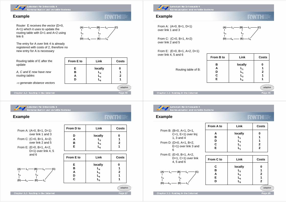
Page 25Chapter 3.2: Routing in the Internet
From E to Link Costs
E locally 0B L4 1A L4 2D L6 1
Router E receives the vector (D=0, A=1) which it uses to update the routing table with D=1 and A=2 using link 6
The entry for A over link 4 is already registered with costs of 2, therefore no new entry for A is necessary
Routing table of E after the update
A, C and E now have new routing tables
⇒ generate distance vectors
Example
adaptive
(A) L1 (B) L2 (C)
(D) L6 (E) L5
L3 L4
Lehrstuhl für Informatik 4
Kommunikation und verteilte Systeme
Page 26Chapter 3.2: Routing in the Internet
From B to Link Costs
B locally 0A L1 1D L1 2C L2 1E L4 1
From A: (A=0, B=1, D=1) over link 1 and 3
From C: (C=0, B=1, A=2) over link 2 and 5
From E: (E=0, B=1, A=2, D=1) over link 4, 5 and 6
Routing table of B:
Example
adaptive
(A) L1 (B) L2 (C)
(D) L6 (E) L5
L3 L4
Lehrstuhl für Informatik 4
Kommunikation und verteilte Systeme
Page 27Chapter 3.2: Routing in the Internet
From D to Link Costs
D locally 0A L3 1B L3 2E L6 1
From E to Link Costs
E locally 0B L4 1A L4 2D L6 1C L5 1
From A: (A=0, B=1, D=1) over link 1 and 3
From C: (C=0, B=1, A=2) over link 2 and 5
From E: (E=0, B=1, A=2, D=1) over link 4, 5 and 6
Example
adaptive
(A) L1 (B) L2 (C)
(D) L6 (E) L5
L3 L4
Lehrstuhl für Informatik 4
Kommunikation und verteilte Systeme
Page 28Chapter 3.2: Routing in the Internet
From C to Link Costs
C locally 0B L2 1A L2 2E L5 1D L5 2
From A to Link Costs
A locally 0B L1 1D L3 1C L1 2E L1 2
From B: (B=0, A=1, D=1, C=1, E=1) over linj1, 3 and 4
From D: (D=0, A=1, B=2, E=1) over link 3 and 6
From E: (E=0, B=1, A=2, D=1, C=1) over link 4, 5 and 6
Example
adaptive
(A) L1 (B) L2 (C)
(D) L6 (E) L5
L3 L4

Lehrstuhl für Informatik 4
Kommunikation und verteilte Systeme
Page 29Chapter 3.2: Routing in the Internet
From D to Link Costs
D locally 0A L3 1B L3 2E L6 1C L6 2
From B: (B=0, A=1, D=1, C=1, E=1) over link 1, 3 and 4
From D: (D=0, A=1, B=2, E=1) over link 3 and 6
From E: (E=0, B=1, A=2, D=1, C=1) over link 4, 5 and 6
Algorithm terminates since A, C and D create and send new vectors, but B, D and E do not have to apply updates any longer.
Example
adaptive
(A) L1 (B) L2 (C)
(D) L6 (E) L5
L3 L4
Lehrstuhl für Informatik 4
Kommunikation und verteilte Systeme
Page 30Chapter 3.2: Routing in the Internet
Problem with this procedure: Information must be reliable
Otherwise: Christmas Deadlock
A router j announced Uj = (0,…, 0)
Consequence: Nearly the entire traffic was led over j
⇒ Collapse
Disadvantages:
- Unreliable information is dangerous- Cycling load conditions
- Additional overhead- And: information propagation lasts a certain time!
Successive Information Spreading
Lehrstuhl für Informatik 4
Kommunikation und verteilte Systeme
Page 31Chapter 3.2: Routing in the Internet
L1 (B) L2 (C)
Router A and B notice the interruption e.g. by control packets
⇒ Update of their own routing tables
⇒ inf = infinite
From A to Link Costs
A locally 0B L1 infD L3 1C L1 infE L1 inf
From B to Link Costs
B locally 0A L1 infD L1 infC L2 1E L4 1
Connection Loss
adaptive
(D) L6 (E) L5
L3 L4
(A)
Lehrstuhl für Informatik 4
Kommunikation und verteilte Systeme
Page 32Chapter 3.2: Routing in the Internet
(A) L1 (B) L2 (C)
(D) L6 (E) L5
From D to Link Costs
D locally 0A L3 1B L3 infE L6 1C L6 2
From A: (A=0, B=inf, D=1, C=inf, E=inf) over link 3
From B: (B=0, A=inf, D=inf, C=1, E=1) over link 2 and 4
D receives the vector from Aand updates with A=1, B=inf, D=2, C=inf, E=inf
Connection Loss
adaptive
L3 L4

Lehrstuhl für Informatik 4
Kommunikation und verteilte Systeme
Page 33Chapter 3.2: Routing in the Internet
From E to link costs
E locally 0B L4 1A L4 infD L6 1C L5 1
From C to link costs
C locally 0B L2 1A L2 infE L5 1D L5 2
From A: (A=0, B=inf, D=1, C=inf, E=inf) over link 3
From B: (B=0, A=inf, D=inf, C=1, E=1) over link 2 und 4
Connection Loss
adaptive
(A) L1 (B) L2 (C)
(D) L6 (E) L5
L3 L4
Lehrstuhl für Informatik 4
Kommunikation und verteilte Systeme
Page 34Chapter 3.2: Routing in the Internet
From D: (D=0, A=1, B=inf, E=1, C=2) over link 3 and 6
From C: (C=0, B=1, A=inf, E=1, D=1) over link 2 and 5
From E: (E=0, B=1, A=inf, D=1, C=1) over link 4, 5 and 6
Connection Loss
adaptive
From A to Link Costs
A locally 0B L1 infD L3 1C L3 3E L3 2
From B to Link Costs
B locally 0A L1 infD L4 2C L2 1E L4 1
(A) L1 (B) L2 (C)
(D) L6 (E) L5
L3 L4
Lehrstuhl für Informatik 4
Kommunikation und verteilte Systeme
Page 35Chapter 3.2: Routing in the Internet
From D: (D=0, A=1, B=inf, E=1, C=2) over link 3 and 6
From C: (C=0, B=1, A=inf, E=1, D=1) over link 2 and 5
From E: (E=0, B=1, A=inf, D=1, C=1) over link 4, 5 and 6
Connection Loss
adaptive
From D to Link Costs
D locally 0A L3 1B L6 2E L6 1C L6 2
From E to Link Costs
E locally 0B L4 1A L6 2D L6 1C L5 1
(A) L1 (B) L2 (C)
(D) L6 (E) L5
L3 L4
Lehrstuhl für Informatik 4
Kommunikation und verteilte Systeme
Page 36Chapter 3.2: Routing in the Internet
From A: (A=0, B=inf, D=1, C=3, E=2) over link 3
From B: (B=0, A=inf, D=2, C=1, D=1) over link 2 and 4
From D: (D=0, A=1, B=2, E=1, C=2) over link 3 and 6
From E: (E=0, B=1, A=2, D=1, C=1) over link 4, 5 and 6
Connection Loss
adaptive
From B to Link Costs
B locally 0A L4 3D L4 2C L2 1E L4 1
From A to Link Costs
A locally 0B L3 3D L3 1C L3 3E L3 2
(A) L1 (B) L2 (C)
(D) L6 (E) L5
L3 L4

Lehrstuhl für Informatik 4
Kommunikation und verteilte Systeme
Page 37Chapter 3.2: Routing in the Internet
From A: (A=0, B=inf, D=1, C=3, E=2) over link 3
From B: (B=0, A=inf, D=2, C=1, D=1) over link 2 and 4
From D: (D=0, A=1, B=2, E=1, C=2) over link 3 and 6
From E: (E=0, B=1, A=2, D=1, C=1) over link 4, 5 and 6
Algorithm terminates, because A, B and C create and send new vectors, but don´t cause further updates in the routing tables.
Connection Loss
adaptive
From C to Link Costs
C locally 0B L2 1A L5 3E L5 1D L5 2
(A) L1 (B) L2 (C)
(D) L6 (E) L5
L3 L4
Lehrstuhl für Informatik 4
Kommunikation und verteilte Systeme
Page 38Chapter 3.2: Routing in the Internet
(D) L6 (E) L5
So far: Costs of 1 for each link
Reality: Different costs per link
Example: Link 5 has costs of 10
In the following, only the paths to router C are examined.
In the case of stable conditions the tables of the other routers have these entries for C:
The Bouncing Effect
adaptive
L1 (B) L2 (C)
L3 L4
(A)1
1
1
1
1
10
From Link Costs
A to C L1 2B to C L2 1C to C locally 0D to C L3 3E to C L4 2
Lehrstuhl für Informatik 4
Kommunikation und verteilte Systeme
Page 39Chapter 3.2: Routing in the Internet
Assumption 1: Connection 2 breaks down.
B detects the failure and sets its costs to inf.
Temporarily, the following table results:
Assumption 2: A has sent its vector before B.
The Bouncing Effect
adaptive
From Link Costs
A to C L1 2B to C L2 infC to C locally 0D to C L3 3E to C L4 2
(in case of regular transmission)
(D) L6 (E) L5
L1 (B) L2 (C)
L3 L4
(A)1
1
1
1
1
10
Lehrstuhl für Informatik 4
Kommunikation und verteilte Systeme
Page 40Chapter 3.2: Routing in the Internet
⇒ A reports C over link 1 with costs of 2
⇒ Router B adds costs of 1 to link 1 for C
⇒ Value is lower than inf
⇒ Table entry for C is replaced by link 1 and costs of 3
⇒ Passing on the table to A and E
⇒ Message comes over link 1 resp. 4, which A and E are using for C
⇒ Update of A and E
The Bouncing Effect
adaptive
From Link Costs
A to C L1 4B to C L1 3C to C locally 0D to C L3 3E to C L4 4
(D) L6 (E) L5
L1 (B) L2 (C)
L3 L4
(A)1
1
1
1
1
10

Lehrstuhl für Informatik 4
Kommunikation und verteilte Systeme
Page 41Chapter 3.2: Routing in the Internet
⇒ Routing tables contain a loop!
⇒ Packets from C are bouncing between A and B
⇒ E adds costs of 10 to its own costs of 0
⇒ E ignores the message, because the costs are higher as before
C sends its vector over link 5
A and E send vectors
⇒ Update of B and D
The Bouncing Effect
adaptive
From Link Costs
A to C L1 4B to C L1 5C to C locally 0D to C L3 5E to C L4 4
(D) L6 (E) L5
L1 (B) L2 (C)
L3 L4
(A)1
1
1
1
1
10
Lehrstuhl für Informatik 4
Kommunikation und verteilte Systeme
Page 42Chapter 3.2: Routing in the Internet
After several iterations, the following tables result:
Entries depend however on random processes (e.g. on the order of the update messages, the arrival times of the vectors, losses of vectors etc.)
The Bouncing Effect
adaptive
From Link Costs
A to C L1 12B to C L4 11C to C locally 0D to C L6 11E to C L5 10
Lehrstuhl für Informatik 4
Kommunikation und verteilte Systeme
Page 43Chapter 3.2: Routing in the Internet
Count to Infinity problem:
The Distance Vector Routing achieves a correct solution, but possibly many (up to infinite) update steps are necessary.
Example:5 routers A, B, C, D, E, are connected linearly, the distance between neighbor routers in each case is 1
A B C D E1 1 11
Count to Infinity
adaptive
Lehrstuhl für Informatik 4
Kommunikation und verteilte Systeme
Page 44Chapter 3.2: Routing in the Internet
Example 1: A at first is switched off, then it is switched on
Count to Infinity
adaptive
43214. Update
∞3213. Update
∞∞212. Update
∞∞∞1A switched on
∞∞∞∞to A
A B C D E

Lehrstuhl für Informatik 4
Kommunikation und verteilte Systeme
Page 45Chapter 3.2: Routing in the Internet
87876. Update
65654. Update
45453. Update
43432. Update
43231. Update
4321A switched off
Example 2: A is switched off
Count to Infinity
adaptive
A B C D E
::∞
......
...... :
:∞
::∞
::∞
Lehrstuhl für Informatik 4
Kommunikation und verteilte Systeme
Page 46Chapter 3.2: Routing in the Internet
A B
C
D
First solution approach: Split-Horizon Algorithm
Do not send the distance to X over that link used to transfer packets for X (resp. path is reported as inf).
However, it does not work always:• Link CD is switched off• C announces A and B that D is unreachable• B announces however to A: D has distance 2• A updates and has D with distance 3• B updates for D with distance 4 ......• Count to Infinity
Split Horizon Algorithm
adaptive
Router
Lehrstuhl für Informatik 4
Kommunikation und verteilte Systeme
Page 47Chapter 3.2: Routing in the Internet
• Early internal gateway routing protocol used in the Internet
• Bases on the Distance Vector Protocol• RIP messages are sent every 30 seconds as UDP datagrams• As metric for the evaluation of the paths the number of hops is used (The
maximal possible number of hops is limited to 15!)• In a message (only) up to 25 entries of the routing table can be sent• Fits good for small systems
• Problems: slow convergence (duration of minutes), Count to Infinity, no addressing of subnets
• RIPv2: subnets, authentication, multicast,… however: the maximal possible number of hops is still limited to 15.
• As reaction to the restrictions of RIP, Cisco introduced the Internet Gateway Routing Protocol (IGRP): Extension of the metric, load sharing, more efficient packet format. The protocols did not become generally accepted, because they were Cisco-specific…
• Replacement by a Link State Protocol (OSPF)
Routing Information Protocol (RIP)
Lehrstuhl für Informatik 4
Kommunikation und verteilte Systeme
Page 48Chapter 3.2: Routing in the Internet
1.) Information exchange with neighborsDistance Vector Routing
2.) Global information exchangeLink State Routing
Routers exchange Link State Advertisements (LSA)
Extension
adaptive

Lehrstuhl für Informatik 4
Kommunikation und verteilte Systeme
Page 49Chapter 3.2: Routing in the Internet
Every router
• determines its neighbors and their addresses (with so-called HELLO packets)
• measures the distances to the neighbors (with so-called ECHO packets)
• sends these information in a packet to all other routers (LSA – Link State Advertisement)
• computes on the basis of all the received LSAs from other routers the shortest paths to the other routers (e.g. with the Dijkstra algorithm)
This is repeated regularly.
Link State Routing
adaptive
Lehrstuhl für Informatik 4
Kommunikation und verteilte Systeme
Page 50Chapter 3.2: Routing in the Internet
A
B
C
D E
F
G
H
I
LAN
First step:
Determination of all neighbored routers
• Sending of a HELLO message on all links
• Routers at the other end answer with their identification
• If several routers are connected in a (broadcast) network, a new “artificial”node is introduced for simplification
A
B
C
D E
F
G H
IN
Link State Routing
adaptive
Lehrstuhl für Informatik 4
Kommunikation und verteilte Systeme
Page 51Chapter 3.2: Routing in the Internet
A
B C
D
E
F
G
H
IJ
Second step:
Discovery of link costs
• Transmission of ECHO messages
• Routers at the other end answer immediately (measurement of the delay)
• Inclusion of load leads to the choice of the lowest loaded link
Side-effect in having two possible links: the less loaded link is loaded immediately heavily and the other link becomes free, with the next measurement the same happens for the other link, … (cycling load)
Link State Routing
adaptive
Lehrstuhl für Informatik 4
Kommunikation und verteilte Systeme
Page 52Chapter 3.2: Routing in the Internet
A
B C
D
E F5
1
24
67
8
ASeq.No.
Age
B 4E 5
BSeq.No.
Age
A 4C 2
F 6
DSeq.No.
Age
C 3F 7
CSeq.No.
Age
B 2D 3
E 1
ESeq.No.
Age
A 5C 1
F 8
FSeq.No.
Age
B 6D 7
E 8
Third step:
Create link state messages
• Contain list of neighbors with appropriate “link costs” (Delay, queue length, jitter etc.)
• Messages additionally contain sender identification, sequence number, age
Link State Routing
adaptive
3

Lehrstuhl für Informatik 4
Kommunikation und verteilte Systeme
Page 53Chapter 3.2: Routing in the Internet
Fourth step:
Sending of link state messages
• Flooding (problem: loops, duplicates, packet losses etc.)
• Sequence numbers are counted up, packets with outdated numbers (duplicates) are discarded
• Every router reduces the “age” “by one, with zero a packet is discarded
• Each router confirms the arrival of a link state packet to the sending router A
F
E
C
D
21
21
21
20
21
60
60
59
60
59
0
1
0
1
1
1
1
1
0
0
1
0
0
1
0
1
0
1
0
0
0
0
0
1
1
0
1
1
0
1
Source Seq.No. Age A C AF FC
Transmission flags Confirmation flags
Data
Data structure of router B
Packet Buffer for Router B
adaptive
Lehrstuhl für Informatik 4
Kommunikation und verteilte Systeme
Page 54Chapter 3.2: Routing in the Internet
• Link state message from A arrives directly, therefore Age=60, Seq.No.=21
• Message is sent to C and F and confirmed for A
• Message of F must be transferred to A and Cand be confirmed for F
• Message of E cametwice (over EAB and EFB) therefore onlyforwarding to C, confirmation forA and F
A
F
E
C
D
21
21
21
20
21
60
60
59
60
59
0
1
0
1
1
1
1
1
0
0
1
0
0
1
0
1
0
1
0
0
0
0
0
1
1
0
1
1
0
1
Source Seq.No. Age A C AF FC
Transmission flags Confirmation flags
Data
Packet Buffer for Router B
adaptive
A
B C
D
E F5
1
24
67
8
3
Lehrstuhl für Informatik 4
Kommunikation und verteilte Systeme
Page 55Chapter 3.2: Routing in the Internet
Fifth step:
Enquiry of best routes
• Router collects link state information from all other routers
• A path graph for the entire sub-network is determined
• Local execution of e.g. the Dijkstra algorithm for the determination of the optimal route
• Results are written into the routing table
Problems:
• With n routers and m neighbors, nm table entries are necessary
• In the case of router failures, the graphs of all routers are outdated
• Extremely susceptibly to attacks
Route Enquiry
adaptive
Lehrstuhl für Informatik 4
Kommunikation und verteilte Systeme
Page 56Chapter 3.2: Routing in the Internet
Problem: extensive routing tables
⇒ hierarchical routing
Large tables are needing too much memory, CPU time, transmission capacity for link state messages etc. ⇒ virtual division of the network
(Regions)
Routing Tables
adaptive

Lehrstuhl für Informatik 4
Kommunikation und verteilte Systeme
Page 57Chapter 3.2: Routing in the Internet
1A 1C
1B 2A
2C
2B
2D
5C
5D5E
4B
5B
5A4C
4A3A
3B
Region 1
Region 5Region 4
Region 2
Region 3
Hierarchical Routing
adaptive
Lehrstuhl für Informatik 4
Kommunikation und verteilte Systeme
Page 58Chapter 3.2: Routing in the Internet
Destination Link to Hops
- -1B 1
123343234445565
1C1B1B1B1B1C1C1C1C1C1C1C1B1C1C
1A1B1C2A2B2C2D3A3B4A4B4C5A5B5C5D5E
Full routing table for 1A Hierarchical routing table for 1A
- -1B 1
12234
1C1B1C1C1C
1A1B1C2345
1A1C
1B 2A
2C
2B
2D
5C
5D5E
4B
5B
5A4C
4A3A
3B
Region 1
Region 5Region 4
Region 2
Region 3
Disadvantage: Possibly increasing path length
Hierarchical Routing
adaptive
Destination Link to Hops
Lehrstuhl für Informatik 4
Kommunikation und verteilte Systeme
Page 59Chapter 3.2: Routing in the Internet
Routing Tables
137.226.0.0
142.117.0.0
12.0.0.0
194.52.124.0
194.52.124.1
142.117.1.10.0.0.0/0 (default)
194.52.124.1194.52.124.0/24
142.117.1.1142.117.0.0/16
142.117.1.1137.226.0.0/16
194.52.124.112.0.0.0/8
Next HopDestination Address
194.52.124.10
142.117.1.7
142.117.1.1
Lehrstuhl für Informatik 4
Kommunikation und verteilte Systeme
Page 60Chapter 3.2: Routing in the Internet
Open Shortest Path First
• Links State protocol
• 1990 standardized by IETF (RFC 1247)
• Open protocol (not manufacturer specific)
• Supports a multiplicity of metrics (distance, delay etc.)
• Dynamic algorithm for fast adjustment to changing conditions in the network
• Load sharing between redundant links
• Supports hierarchical systems
• Contains security mechanisms to protect routers from wrong routing information or attacks
• Three types of connections are supported:
- Point-to-point links between routers- Broadcast networks (mostly LANs)- Multi-access networks without broadcasting (e.g. packet switching
WANs)
Internal Gateway Routing Protocol - OSPF

Lehrstuhl für Informatik 4
Kommunikation und verteilte Systeme
Page 61Chapter 3.2: Routing in the Internet
• The Internet is divided into autonomous systems (AS)
• Very large autonomous systems are divided in areas
• Each autonomous system has a backbone, which connects all parts of the AS
• Every router, which belongs to two or more areas, is part of the backbone
• Within these areas every router has the same link state database and implements the same algorithm for determination of the shortest path
• A router, which connect two areas, needs the link state databases from both areas
• OSPF distinguishes four router classes (for reducing the extent of routing tables):
- Internal routers, which only belong to one area- Area routers at the border of areas, which connect two or more areas- Backbone routers, which are placed at the backbone- AS border routers, which mediate between several autonomous systems
OSPF
Lehrstuhl für Informatik 4
Kommunikation und verteilte Systeme
Page 62Chapter 3.2: Routing in the Internet
Area router
External protocols connectthe autonomous systems
Backbone
Backbonerouter
Area
Internal router
Border router of theautonomous system
AS 1 AS 2
AS 3 AS 4
Relationship between autonomous systems, backbones and areas in OSPF
OSPF
Lehrstuhl für Informatik 4
Kommunikation und verteilte Systeme
Page 63Chapter 3.2: Routing in the Internet
External Gateway Protocol - BGP
Internal gateway protocols are designed for efficiency: find the best way to the destination host.
External gateway protocols must have to consider policies (political, economical,…)
BGP - Border Gateway Protocol
An external routing protocol
• Variant of the Distance Vector Protocol: not the costs of a transmission path are being monitored and exchanged, but the complete description of paths
• Considers security and other rules (Routing Policies)
• Communicates the neighbor routers the whole path which is to be used (deterministically)
• Uses TCP for data exchange
Lehrstuhl für Informatik 4
Kommunikation und verteilte Systeme
Page 64Chapter 3.2: Routing in the Internet
H
A
CB
G
F
E
D
JI
Information sent to F
F receives the following information about D from its neighbors :
from B: “I use BCD”from G: “I use GCD”from I: “I use IFGCD”from E: “I use EFGCD”
Assumption: F uses FGCD to reach D
F searches for the optimal route
• Paths of I and E are directly discarded, because they cross F
• B and G are possible options
• Application of Policies
• Routes, which violate policies, are being set to inf
External Gateway Protocol - BGP
Top Related