


Languages
Pages
Legal


6
0.5mm and 1mm Pitch Connectors For FPC/FFCFH12 Series
■ Features1. Ease of Use and Space Savings
Only one finger or 6.9N (Newtons) of force is required tolock Hirose’s rotational actuator (flip-lock) as comparedto using 2 fingers and 39.2N to close a FFC/FPCconnector from our competition.
The Flip-Lock design also allows customers to place 2or more connectors side by side as there is no need towaste additional board space for a side latch.
2. Strengthened Flip-lock ActuatorThe standard Flip-Lock requires only 2.0mm heightabove the board. A strengthened lock lever is availablewhich only requires an additional 0.4mm.
3. Supports Thin FPC (0.18mm)Hirose does not require double-sided FPC to have anyadditional strengthening plate or stiffener and can thereforesupport a thickness of as little as 0.18mm +/- 0.05.
4. Hirose Ensures ReliabilityHirose’s patented half tuning fork contacts maintain therequired normal force without relying on the connectorhousing. With our competitor’s conventional productsthe housing walls support the contact force, which doesnot provide for long-term reliability.
5. Prevention of Solder Bridge Excess solder cavity absorbs excessive solder andavoids solder bridging.
6. Three different assembly types FH12 is offered in Top & Bottom Contact and VerticalMount and offered in both a 0.5mm contact pitch as wellas a 1.0mm contact pitch (bottom contact only).
■ ApplicationsNotebook computers, printers, PDAs, digital cameras andother compact devices for interconnecting the main circuitboard with the LCD, HDD or other device.
Rotating One-touch Mechanism
q
w
e
Flip-lock
The product information in this catalog is for reference only. Please request the Engineering Drawing for the most current and accurate design information.All non-RoHS products have been discontinued, or will be discontinued soon. Please check the products status on the Hirose website RoHS search at www.hirose-connectors.com, or contact your Hirose sales representative.
7
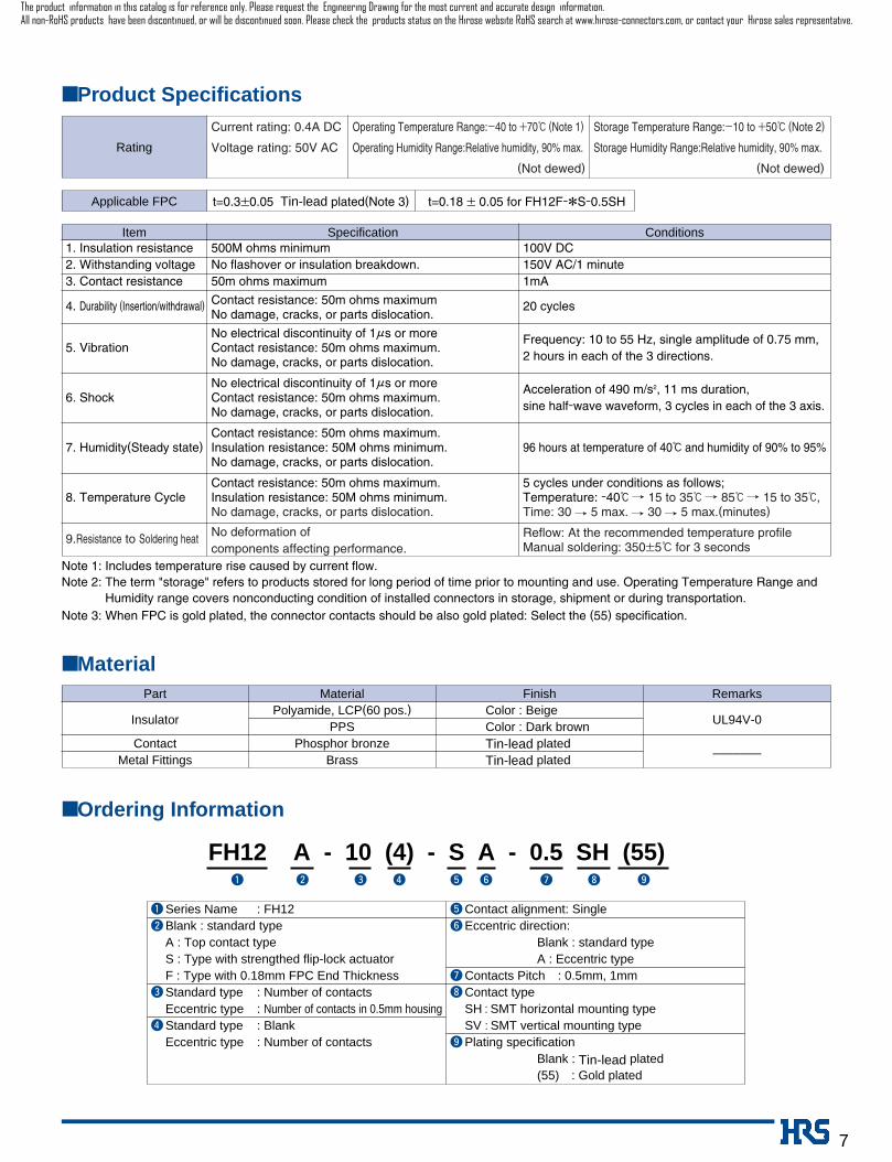
■ Product Specifications
Rating
Current rating: 0.4A DC Operating Temperature Range:_40 to +70ç (Note 1) Storage Temperature Range:_10 to +50ç (Note 2)
Voltage rating: 50V AC Operating Humidity Range:Relative humidity, 90% max. Storage Humidity Range:Relative humidity, 90% max.
(Not dewed) (Not dewed)
Applicable FPC t=0.3±0.05 Tin-lead plated(Note 3) t=0.18 ± 0.05 for FH12F-*S-0.5SH
Note 1: Includes temperature rise caused by current flow.Note 2: The term "storage" refers to products stored for long period of time prior to mounting and use. Operating Temperature Range and
Humidity range covers nonconducting condition of installed connectors in storage, shipment or during transportation.Note 3: When FPC is gold plated, the connector contacts should be also gold plated: Select the (55) specification.
■ MaterialPart Material Finish Remarks
InsulatorPolyamide, LCP(60 pos.) Color : Beige
UL94V-0PPS Color : Dark brownContact Phosphor bronze Tin-lead plated
–––––––Metal Fittings Brass Tin-lead plated
■ Ordering Information
FH12 A - 10 (4) - S A - 0.5 SH (55)q e rw yt u i o
qSeries Name : FH12wBlank : standard type
A : Top contact typeS : Type with strengthed flip-lock actuatorF : Type with 0.18mm FPC End Thickness
eStandard type : Number of contactsEccentric type : Number of contacts in 0.5mm housing
rStandard type : BlankEccentric type : Number of contacts
tContact alignment: SingleyEccentric direction:
Blank : standard typeA : Eccentric type
uContacts Pitch : 0.5mm, 1mmiContact type
SH : SMT horizontal mounting typeSV : SMT vertical mounting typePlating specification
Blank : Tin-lead plated(55) : Gold plated
o
1. Insulation resistance 500M ohms minimum 100V DC2. Withstanding voltage No flashover or insulation breakdown. 150V AC/1 minute3. Contact resistance 50m ohms maximum 1mA
4. Durability (Insertion/withdrawal) Contact resistance: 50m ohms maximum 20 cyclesNo damage, cracks, or parts dislocation.
No electrical discontinuity of 1µs or more Frequency: 10 to 55 Hz, single amplitude of 0.75 mm,5. Vibration Contact resistance: 50m ohms maximum.
2 hours in each of the 3 directions.No damage, cracks, or parts dislocation.
No electrical discontinuity of 1µs or more Acceleration of 490 m/s2, 11 ms duration,6. Shock Contact resistance: 50m ohms maximum.
sine half-wave waveform, 3 cycles in each of the 3 axis.No damage, cracks, or parts dislocation.
Contact resistance: 50m ohms maximum.7. Humidity(Steady state) Insulation resistance: 50M ohms minimum. 96 hours at temperature of 40ç and humidity of 90% to 95%
No damage, cracks, or parts dislocation.
Contact resistance: 50m ohms maximum. 5 cycles under conditions as follows;8. Temperature Cycle Insulation resistance: 50M ohms minimum. Temperature: -40ç / 15 to 35ç / 85ç / 15 to 35ç,
No damage, cracks, or parts dislocation. Time: 30 / 5 max. / 30 / 5 max.(minutes)
9.Resistance to Soldering heat No deformation of Reflow: At the recommended temperature profilecomponents affecting performance. Manual soldering: 350±5ç for 3 seconds
Item Specification Conditions
The product information in this catalog is for reference only. Please request the Engineering Drawing for the most current and accurate design information.All non-RoHS products have been discontinued, or will be discontinued soon. Please check the products status on the Hirose website RoHS search at www.hirose-connectors.com, or contact your Hirose sales representative.

8
BSeries Configuration
FH12- ** S-0.5SHNumber of contacts 6, 10, 11, 12, 13, 14,
15, 16, 17, 18, 19, 20,
22, 24, 25, 26, 28, 30,
32, 33, 34, 36, 40, 45,
50, 53
FH12F- ** S-0.5SHNumber of contacts 6, 10, 12, 13, 14, 15, 16,
18, 20, 22, 24, 26, 28,
30, 32, (33), 34, 36, 40
FH12S- ** S-0.5SHNumber of contacts 30, 40, 45, 50, 53
Standard FH12- ** S-1SHEccentric FH12- ** (**) S-1SHStandard
Number of contacts 5, 6, 7, 8, 9, 11,
16, 22, 26
Eccentric
Number of contacts 4, 6, 8, 10, 11,
14, 19, 24
FH12- ** S-1SV
Number of contacts 6, 7, 8, 16, 20, 22,
24
Pitch
0.5mm
1mm
Bottom Contact Type
Type with Strengthened Lock Lever
Type with 0.18mm FPC End Thickness
Top Contact Type Vertical mounting Type
P.13
P.12
P.14
P.18
P.19
FH12- ** S-0.5SVNumber of contacts 10, 12, 13, 15, 16, 17,
18, 20, 22, 24, 26, 30,
32, 33, 34, 36, 40, 45,49, 50, 60
P.16FH12A- ** S-0.5SHNumber of contacts 10, 12 ,15, 16, 18, 20,
22, 24, 26, 28, 29, 30,32, 33, 34, 36, 40, 42,45, 50
P.15
FPC conductive
surface
FPC conductive surface
(bottom side)
FPC conductive surface
(bottom side)
The product information in this catalog is for reference only. Please request the Engineering Drawing for the most current and accurate design information.All non-RoHS products have been discontinued, or will be discontinued soon. Please check the products status on the Hirose website RoHS search at www.hirose-connectors.com, or contact your Hirose sales representative.

Operation Precautions
9
BConnector Operating Instructions, precautions and recommendations● Bottom Contact Type (common for 0.5mm/1mm)
1. FPC/FFC Termination procedure.Connector installed on the board.
1) Lift up the actuator. Use thumb or index finger.
1) Avoid grasping the actuator with two fingers or lift-ing the actuator with fingernail.
2) Rotate down the actuator until firmly closed.It is critical that the inserted FPC/FFC is not movedand remains fully inserted. Should the FPC/FFC bemoved, open the actuator and repeat the process,starting with Step 1 above.
2) Fully insert the FPC/FFC parallel to mounting sur-face, with the exposed conductive traces facingdown.
2. FPC/FFC Removal1) Lift up the actuator.2) Carefully remove the FPC/FFC.
3) Due to the structure of the connectors, they donot have strong resistance to upward pulling;therefore, support the FPC/FFC when a pullingforce is applied to it.
Stiffener
FPC/FFC conductive traces
The product information in this catalog is for reference only. Please request the Engineering Drawing for the most current and accurate design information.All non-RoHS products have been discontinued, or will be discontinued soon. Please check the products status on the Hirose website RoHS search at www.hirose-connectors.com, or contact your Hirose sales representative.

10
● Top Contact Type
Operation Precautions
1. FPC/FFC Termination procedure.Connector installed on the board.
1) Lift up the actuator. Use thumb or index finger.
2) Fully insert the FPC/FFC parallel to mounting sur-face, with the exposed conductive traces facingUP.
3) Rotate down the actuator until firmly closed.It is critical that the inserted FPC/FFC is not movedand remains fully inserted. Should the FPC/FFC bemoved, open the actuator and repeat the process,starting with Step 1 above.
2. FPC/FFC Removal1) Lift up the actuator.2) Carefully remove the FPC/FFC.
FPC/FFC conductive traces
Stiffener
FPC insertion area
1) Avoid forcing the actuator up or down without theFPC/FFC inserted.
2) When closing down the actuator apply equal pres-sure to both sides of the actuator.
3) Avoid forced pulling of the FPC. Forced pullingwill cause the FPC to become disconnected ordamaged.
The product information in this catalog is for reference only. Please request the Engineering Drawing for the most current and accurate design information.All non-RoHS products have been discontinued, or will be discontinued soon. Please check the products status on the Hirose website RoHS search at www.hirose-connectors.com, or contact your Hirose sales representative.

11
● Vertical Mounting Type
Operation Precautions
1. FPC/FFC Termination procedure.Connector installed on the board.
1) Verify that the actuator is positioned upright. If theactuator has rotated to the side, carefully rotate itupright.
2) Insert the FPC/FFC vertically in the connector slotassuring that the conductive traces of theFPC/FFC are facing away from the actuator.
3) Press down the actuator in the direction shown.
2. FPC/FFC RemovalRotate the actuator upward and withdraw theFPC/FFC.
1) Avoid forcing the actuator up or down without theFPC/FFC inserted.
FPC/FFC conductive traces
Actuator upright
Stiffener
Slot
The product information in this catalog is for reference only. Please request the Engineering Drawing for the most current and accurate design information.All non-RoHS products have been discontinued, or will be discontinued soon. Please check the products status on the Hirose website RoHS search at www.hirose-connectors.com, or contact your Hirose sales representative.

12
■ 0.5mm Pitch Bottom Contact Type
2
(0.2)0.5
0.8
21.
2
1.85
5.64.6
(4.8
)2
FPC/FFC Contact Surface (2.1)
Mated Cross-sectional Diagram
(3.1) (1.3)
A
BC
D
Note 1 : Embossed tape reel packaging (2,000 pieces/reel).Order by number of reels.
Note : If there is no problem with the connector height, we recommend the type with thestrengthened Flip-lock actuator (FH12S-*S-0.5SH).
Standard type connector height: 2 mm Connector height of type with strengthened Flip-lock actuator: 2.4 mm
D
Unit:mm
CL No.Part Number
586-0582-5
586-0522-3
586-0600-5
586-0704-0
586-0549-0
586-0533-0
586-0523-6
586-0531-4
586-0606-1
586-0530-1
586-0534-2
586-0524-9
586-0532-7
586-0521-0
586-0692-3
586-0576-2
586-0612-4
586-0525-1
586-0681-7
586-0520-8
586-0617-8
586-0526-4
586-0527-7
586-0528-0
586-0529-2
586-0595-7
FH12-06S-0.5SH
FH12-10S-0.5SH
FH12-11S-0.5SH
FH12-12S-0.5SH
FH12-13S-0.5SH
FH12-14S-0.5SH
FH12-15S-0.5SH
FH12-16S-0.5SH
FH12-17S-0.5SH
FH12-18S-0.5SH
FH12-19S-0.5SH
FH12-20S-0.5SH
FH12-22S-0.5SH
FH12-24S-0.5SH
FH12-25S-0.5SH
FH12-26S-0.5SH
FH12-28S-0.5SH
FH12-30S-0.5SH
FH12-32S-0.5SH
FH12-33S-0.5SH
FH12-34S-0.5SH
FH12-36S-0.5SH
FH12-40S-0.5SH
FH12-45S-0.5SH
FH12-50S-0.5SH
FH12-53S-0.5SH
Number of Contacts
6
10
11
12
13
14
15
16
17
18
19
20
22
24
25
26
28
30
32
33
34
36
40
45
50
53
A B
02.5
04.5
05.0
05.5
06.0
06.5
07.0
07.5
08.0
08.5
09.0
09.5
10.5
11.5
12.0
12.5
13.5
14.5
15.5
16.0
16.5
17.5
19.5
22.0
24.5
26.0
06.1
08.1
08.6
09.1
09.6
10.1
10.6
11.1
11.6
12.1
12.6
13.1
14.1
15.1
15.6
16.1
17.1
18.1
19.1
19.6
20.1
21.1
23.1
25.6
28.1
29.6
C
07.1
09.1
09.6
10.1
10.6
11.1
11.6
12.1
12.6
13.1
13.6
14.1
15.1
16.1
16.6
17.1
18.1
19.1
20.1
20.6
21.1
22.1
24.1
26.6
29.1
30.6
03.57
05.57
06.07
06.57
07.07
07.57
08.07
08.57
09.07
09.57
10.07
10.57
11.57
12.57
13.07
13.57
14.57
15.57
16.57
17.07
17.57
18.57
20.57
23.07
25.57
27.072
2
2
2
2Note
Note
Note
Note
Note
2
The product information in this catalog is for reference only. Please request the Engineering Drawing for the most current and accurate design information.All non-RoHS products have been discontinued, or will be discontinued soon. Please check the products status on the Hirose website RoHS search at www.hirose-connectors.com, or contact your Hirose sales representative.

13
Note: Embossed tape reel packaging (2,000 pieces/reel).Order by number of reels.
D
Unit:mm
CL No.Part Number
586-0667-6
586-0640-0
586-0665-0
586-0642-5
586-0691-0
FH12S-30S-0.5SH
FH12S-40S-0.5SH
FH12S-45S-0.5SH
FH12S-50S-0.5SH
FH12S-53S-0.5SH
Number of Contacts
30
40
45
50
53
A B
14.5
19.5
22.0
24.5
26.0
18.1
23.1
25.6
28.1
29.6
C
19.1
24.1
26.6
29.1
30.6
15.57
20.57
23.07
25.57
27.07
■ 0.5mm Pitch Bottom Contact Type with Strengthened Flip-lock Actuator
FPC/FFC Contact Surface
Mated Cross-sectional Diagram
2
CB
1.2
20.
8
0.20.5
A
( 4.8
)
2.1
3.1 1.3
2.25
2.4
D 4.65.6
( )
( ) ( )
( )
The product information in this catalog is for reference only. Please request the Engineering Drawing for the most current and accurate design information.All non-RoHS products have been discontinued, or will be discontinued soon. Please check the products status on the Hirose website RoHS search at www.hirose-connectors.com, or contact your Hirose sales representative.

14
Applicable FPC end thickness : 0.18±0.05
■ 0.5mm Pitch Bottom Contact Type with 0.18mm FPC End Thickness
0.20.5
A
0.8
21.
2
BC
D
1.85
2
5.64.6
4.8
FPC Contact Surface
3.15
2.15
1.25
Mated Cross-sectional Diagram( )
( )( )
( )
()
Note: Embossed tape reel packaging (2,000 pieces/reel).Order by number of reels.
D
Unit:mm
CL No.Part Number
586-0672-6
586-0709-4
586-0653-1
586-0629-7
586-0655-7
586-0680-4
586-0673-9
586-0626-9
586-0636-2
586-0630-6
586-0632-1
586-0627-1
586-0643-8
586-0628-4
586-0705-3
--------------------
586-0677-0
586-0656-0
586-0635-0
FH12F-06S-0.5SH
FH12F-10S-0.5SH
FH12F-12S-0.5SH
FH12F-13S-0.5SH
FH12F-14S-0.5SH
FH12F-15S-0.5SH
FH12F-16S-0.5SH
FH12F-18S-0.5SH
FH12F-20S-0.5SH
FH12F-22S-0.5SH
FH12F-24S-0.5SH
FH12F-26S-0.5SH
FH12F-28S-0.5SH
FH12F-30S-0.5SH
FH12F-32S-0.5SH
FH12F-33S-0.5SH
FH12F-34S-0.5SH
FH12F-36S-0.5SH
FH12F-40S-0.5SH
Number of Contacts
6
10
12
13
14
15
16
18
20
22
24
26
28
30
32
33
34
36
40
A B
02.5
04.5
05.5
06.0
06.5
07.0
07.5
08.5
09.5
10.5
11.5
12.5
13.5
14.5
15.5
16.0
16.5
17.5
19.5
06.1
08.1
09.1
09.6
10.1
10.6
11.1
12.1
13.1
14.1
15.1
16.1
17.1
18.1
19.1
19.6
20.1
21.1
23.1
C
07.1
09.1
10.1
10.6
11.1
11.6
12.1
13.1
14.1
15.1
16.1
17.1
18.1
19.1
20.1
20.6
21.1
22.1
24.1
03.57
05.57
06.57
07.07
07.57
08.07
08.57
09.57
10.57
11.57
12.57
13.57
14.57
15.57
16.57
17.07
17.57
18.57
20.57
The product information in this catalog is for reference only. Please request the Engineering Drawing for the most current and accurate design information.All non-RoHS products have been discontinued, or will be discontinued soon. Please check the products status on the Hirose website RoHS search at www.hirose-connectors.com, or contact your Hirose sales representative.

15
D E
Unit:mm
CL No.Part Number
586-0550-9
586-0696-4
586-0551-1
586-0552-4
586-0553-7
586-0554-0
586-0686-0
586-0555-2
586-0663-5
586-0725-0
586-0585-3
586-0556-5
586-0687-3
586-0570-6
586-0670-0
586-0662-2
586-0557-8
586-0698-0
586-0558-0
586-0559-3
FH12A-10S-0.5SH
FH12A-12S-0.5SH
FH12A-15S-0.5SH
FH12A-16S-0.5SH
FH12A-18S-0.5SH
FH12A-20S-0.5SH
FH12A-22S-0.5SH
FH12A-24S-0.5SH
FH12A-26S-0.5SH
FH12A-28S-0.5SH
FH12A-29S-0.5SH
FH12A-30S-0.5SH
FH12A-32S-0.5SH
FH12A-33S-0.5SH
FH12A-34S-0.5SH
FH12A-36S-0.5SH
FH12A-40S-0.5SH
FH12A-42S-0.5SH
FH12A-45S-0.5SH
FH12A-50S-0.5SH
Number of Contacts
10
12
15
16
18
20
22
24
26
28
29
30
32
33
34
36
40
42
45
50
A B
9.1
10.1
11.6
12.1
13.1
14.1
15.1
16.1
17.1
18.1
18.6
19.1
20.1
20.6
21.1
22.1
24.1
25.1
26.6
29.1
8.35
9.35
10.85
11.35
12.35
13.35
14.35
15.35
16.35
17.35
17.85
18.35
19.35
19.85
20.35
21.35
23.35
24.35
25.85
28.35
C
4.5
5.5
7.0
7.5
8.5
9.5
10.5
11.5
12.5
13.5
14.0
14.5
15.5
16.0
16.5
17.5
19.5
20.5
22.0
24.5
9.5
10.5
12.0
12.5
13.5
14.5
15.5
16.5
17.5
18.5
19.0
19.5
20.5
21.0
21.5
22.5
24.5
25.5
27.0
29.5
5.57
6.57
8.07
8.57
9.57
10.57
11.57
12.57
13.57
14.57
15.07
15.57
16.57
17.07
17.57
18.57
20.57
21.57
23.07
25.57
■ 0.5mm Pitch Top Contact Type
0.5
2.2
0.85
0.81.45
6.2
2
2
FPC/FFC Contact Surface
Mated Cross-sectional Diagram
(1.45)(1.9)
(5)
(0.45)
(1.8
5)
(3.6
)
(0.2)
ABC
D
E
Note 1 : Embossed tape reel packaging (2,000 pieces/reel).Order by number of reels.
Note : The design is such that the FPC/FFC protrudes on an upward angle so that otherparts can be mounted beneath the PFC/FFC. In view of this, please take note of thegap at the top surface of the connector.
2
The product information in this catalog is for reference only. Please request the Engineering Drawing for the most current and accurate design information.All non-RoHS products have been discontinued, or will be discontinued soon. Please check the products status on the Hirose website RoHS search at www.hirose-connectors.com, or contact your Hirose sales representative.
16
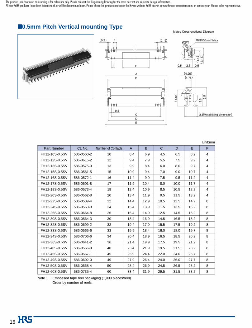
■ 0.5mm Pitch Vertical mounting Type
( 0.15 )10.2
1 F
AB
CDE
3.6 5.
5
1.754.25
( 4.8
5)
0.5
1.4
2.15
0.5 2.5 0.5
Mated Cross-sectional Diagram
FPC/FFC Contact Surface
(())
( )( )
( )
D E
Unit:mm
CL No.Part Number
586-0560-2
586-0615-2
586-0575-0
586-0561-5
586-0572-1
586-0601-8
586-0573-4
586-0562-8
586-0589-4
586-0563-0
586-0664-8
586-0564-3
586-0699-2
586-0565-6
586-0706-6
586-0641-2
586-0566-9
586-0567-1
586-0602-0
586-0568-4
586-0735-4
FH12-10S-0.5SV
FH12-12S-0.5SV
FH12-13S-0.5SV
FH12-15S-0.5SV
FH12-16S-0.5SV
FH12-17S-0.5SV
FH12-18S-0.5SV
FH12-20S-0.5SV
FH12-22S-0.5SV
FH12-24S-0.5SV
FH12-26S-0.5SV
FH12-30S-0.5SV
FH12-32S-0.5SV
FH12-33S-0.5SV
FH12-34S-0.5SV
FH12-36S-0.5SV
FH12-40S-0.5SV
FH12-45S-0.5SV
FH12-49S-0.5SV
FH12-50S-0.5SV
FH12-60S-0.5SV
Number of Contacts
10
12
13
15
16
17
18
20
22
24
26
30
32
33
34
36
40
45
49
50
60
A B
08.4
09.4
09.9
10.9
11.4
11.9
12.4
13.4
14.4
15.4
16.4
18.4
19.4
19.9
20.4
21.4
23.4
25.9
27.9
28.4
33.4
06.9
07.9
08.4
09.4
09.9
10.4
10.9
11.9
12.9
13.9
14.9
16.9
17.9
18.4
18.9
19.9
21.9
24.4
26.4
26.9
31.9
C
04.5
05.5
06.0
07.0
07.5
08.0
08.5
09.5
10.5
11.5
12.5
14.5
15.5
16.0
16.5
17.5
19.5
22.0
24.0
24.5
29.5
06.5
07.5
08.0
09.0
09.5
10.0
10.5
11.5
12.5
13.5
14.5
16.5
17.5
18.0
18.5
19.5
21.5
24.0
26.0
26.5
31.5
08.2
09.2
09.7
10.7
11.2
11.7
12.2
13.2
14.2
15.2
16.2
18.2
19.2
19.7
20.2
21.2
23.2
25.7
27.7
28.2
33.2
F
4
4
4
4
4
4
4
4
8
8
8
8
8
8
8
8
8
8
8
8
8
Note 1 : Embossed tape reel packaging (1,000 pieces/reel).Order by number of reels.
The product information in this catalog is for reference only. Please request the Engineering Drawing for the most current and accurate design information.All non-RoHS products have been discontinued, or will be discontinued soon. Please check the products status on the Hirose website RoHS search at www.hirose-connectors.com, or contact your Hirose sales representative.
17
610111213141516171819202224
02.504.505.005.506.006.507.007.508.008.509.009.510.511.5
03.505.506.006.507.007.508.008.509.009.510.010.511.512.5
2526282930323334364042455053
12.012.513.514.014.515.516.016.517.519.520.522.024.526.0
13.013.514.515.015.516.517.017.518.520.521.523.025.527.0
610111213141516171819202224
02.504.505.005.506.006.507.007.508.008.509.009.510.511.5
08.110.110.611.111.612.112.613.113.614.114.615.116.117.1
04.506.507.007.508.008.509.009.510.010.511.011.512.513.5
2526282930323334364042455053
12.012.513.514.014.515.516.016.517.519.520.522.024.526.0
17.618.119.119.620.121.121.622.123.125.126.127.630.131.6
14.014.515.516.016.517.518.018.519.521.522.524.026.528.0
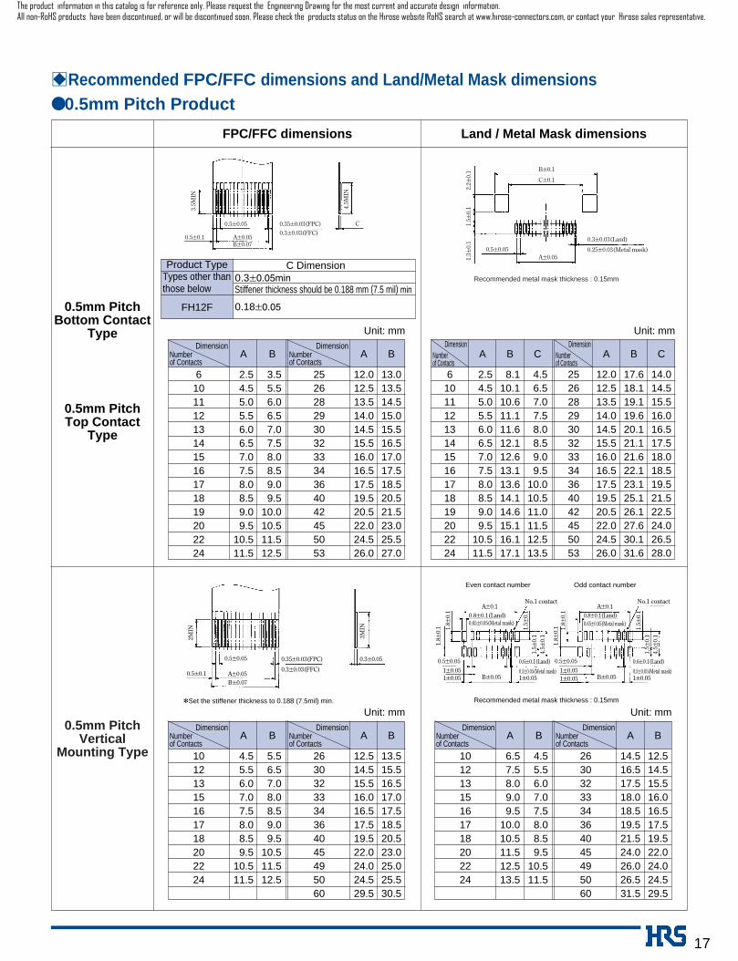
BRecommended FPC/FFC dimensions and Land/Metal Mask dimensions ● 0.5mm Pitch Product
DimensionNumberof Contacts
A B A BDimension
Numberof Contacts
Unit: mmDimension
Numberof Contacts
A B CDimension
Numberof Contacts
A B C
Unit: mm
Land / Metal Mask dimensionsFPC/FFC dimensions
0.5mm PitchBottom Contact
Type
0.5mm PitchTop Contact
Type
C
0.5±0.1
0.5±0.05
A±0.05B±0.07
0.35±0.03(FPC)0.3±0.03(FFC)
3.5M
IN
4.5M
IN
B±0.1
C±0.1
A±0.050.5±0.05
0.3±0.03(Land)
0.25±0.03(Metal mask)
2.2±
0.1
1.5 ±
0.1
1.3±
0.1
Recommended metal mask thickness : 0.15mm
0.5mm PitchVertical
Mounting Type
*Set the stiffener thickness to 0.188 (7.5mil) min.
0.8±0.1(Land)0.65±0.05(Metal mask)
0.6±0.1(Land)
0.5±0.05(Metal mask)0.5±0.1
0.5±0.05 0.3±0.05
A±0.05B±0.07
0.35±0.03(FPC)
Recommended metal mask thickness : 0.15mm
Even contact number Odd contact number
0.3±0.03(FFC)
2MIN
3MIN
0.5±0.051±0.051±0.05 1±0.05
A±0.1
B±0.05
1.8±
0.1 1.
8 ±0.
1
0.8±0.1(Land)0.65±0.05(Metal mask)
0.6±0.1(Land)
0.5±0.05(Metal mask)
0.5±0.051±0.051±0.05 1±0.05
A±0.1No.1 contactNo.1 contact
B±0.05
1.8±
0.1 1.
8 ±0.
1
1.5±
0.1
1.5 ±
0.1
4.5±
0.1
1.5±
0.1
1.5 ±
0.1
4.5±
0.1
10121315161718202224
04.505.506.007.007.508.008.509.510.511.5
05.506.507.008.008.509.009.510.511.512.5
2630323334364045495060
12.514.515.516.016.517.519.522.024.024.529.5
13.515.516.517.017.518.520.523.025.025.530.5
DimensionNumberof Contacts
A B A BDimension
Numberof Contacts
Unit: mm
10121315161718202224
06.507.508.009.009.510.010.511.512.513.5
04.505.506.007.007.508.008.509.510.511.5
2630323334364045495060
14.516.517.518.018.519.521.524.026.026.531.5
12.514.515.516.016.517.519.522.024.024.529.5
DimensionNumberof Contacts
A B A BDimension
Numberof Contacts
Unit: mm
Product Type Types other thanthose below
FH12F
C Dimension0.3±0.05minStiffener thickness should be 0.188 mm (7.5 mil) min
0.18±0.05
The product information in this catalog is for reference only. Please request the Engineering Drawing for the most current and accurate design information.All non-RoHS products have been discontinued, or will be discontinued soon. Please check the products status on the Hirose website RoHS search at www.hirose-connectors.com, or contact your Hirose sales representative.
18
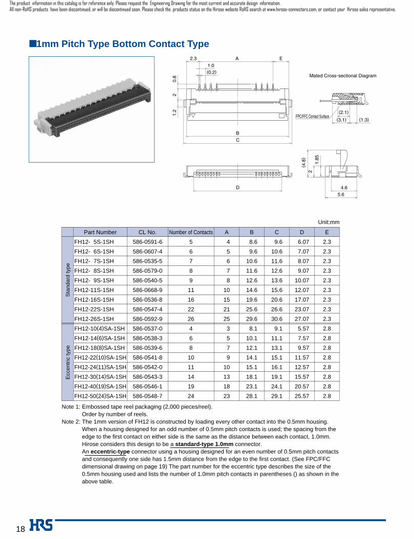
Note 1: Embossed tape reel packaging (2,000 pieces/reel).Order by number of reels.
Note 2: The 1mm version of FH12 is constructed by loading every other contact into the 0.5mm housing. When a housing designed for an odd number of 0.5mm pitch contacts is used; the spacing from theedge to the first contact on either side is the same as the distance between each contact, 1.0mm.Hirose considers this design to be a standard-type 1.0mm connector.
Note 2: An eccentric-type connector using a housing designed for an even number of 0.5mm pitch contactsand consequently one side has 1.5mm distance from the edge to the first contact. (See FPC/FFCdimensional drawing on page 19) The part number for the eccentric type describes the size of the0.5mm housing used and lists the number of 1.0mm pitch contacts in parentheses () as shown in theabove table.
D E
Unit:mm
CL No.Part Number
586-0591-6
586-0607-4
586-0535-5
586-0579-0
586-0540-5
586-0668-9
586-0536-8
586-0547-4
586-0592-9
586-0537-0
586-0538-3
586-0539-6
586-0541-8
586-0542-0
586-0543-3
586-0546-1
586-0548-7
FH12-05S-1SH
FH12-06S-1SH
FH12-07S-1SH
FH12-08S-1SH
FH12-09S-1SH
FH12-11S-1SH
FH12-16S-1SH
FH12-22S-1SH
FH12-26S-1SH
FH12-10(4)SA-1SH
FH12-14(6)SA-1SH
FH12-18(8)SA-1SH
FH12-22(10)SA-1SH
FH12-24(11)SA-1SH
FH12-30(14)SA-1SH
FH12-40(19)SA-1SH
FH12-50(24)SA-1SH
Number of Contacts
5
6
7
8
9
11
16
22
26
4
6
8
10
11
14
19
24
A B
04
05
06
07
08
10
15
21
25
03
05
07
09
10
13
18
23
08.6
09.6
10.6
11.6
12.6
14.6
19.6
25.6
29.6
08.1
10.1
12.1
14.1
15.1
18.1
23.1
28.1
C
09.6
10.6
11.6
12.6
13.6
15.6
20.6
26.6
30.6
09.1
11.1
13.1
15.1
16.1
19.1
24.1
29.1
06.07
07.07
08.07
09.07
10.07
12.07
17.07
23.07
27.07
05.57
07.57
09.57
11.57
12.57
15.57
20.57
25.57
2.3
2.3
2.3
2.3
2.3
2.3
2.3
2.3
2.3
2.8
2.8
2.8
2.8
2.8
2.8
2.8
2.8
Sta
ndar
dty
peE
ccen
tric
type
■ 1mm Pitch Type Bottom Contact Type
(0.2)
(2.1)
(3.1)
(4.8
)
(1.3)
2.3 E
FPC/FFC Contact Surface
D
1.0
A
0.8
21.
2
BC
1.85
2
5.64.6
Mated Cross-sectional Diagram
The product information in this catalog is for reference only. Please request the Engineering Drawing for the most current and accurate design information.All non-RoHS products have been discontinued, or will be discontinued soon. Please check the products status on the Hirose website RoHS search at www.hirose-connectors.com, or contact your Hirose sales representative.

19
Note: Embossed tape reel packaging (1,000 pieces/reel).Order by number of reels.
D E F
Unit:mm
CL No.Part Number
586-0605-9
586-0610-9
586-0593-1
586-0574-7
586-0634-7
586-0584-0
586-0594-4
FH12-06S-1SV
FH12-07S-1SV
FH12-08S-1SV
FH12-16S-1SV
FH12-20S-1SV
FH12-22S-1SV
FH12-24S-1SV
Number of Contacts
6
7
8
16
20
22
24
A B
09.9
10.9
11.9
19.9
23.9
25.9
27.9
08.4
09.4
10.4
18.4
22.4
24.4
26.4
C
05
06
07
15
19
21
23
08
09
10
18
22
24
26
09.7
10.7
11.7
19.7
23.7
25.7
27.7
4
4
4
8
8
8
8
■ 1mm Pitch Vertical Mounting Type
(0.15)(0.2) 2
2 F
AB
CDE
3.8(Metal fitting dimension)
3.6 5.
5
(4.8
5)
(2.1
5)(1
.4)
(4.25)(1.75)
1.0
0.5 2.5 0.5
Mated Cross-sectional Diagram
FPC/FFC Contact Surface
The product information in this catalog is for reference only. Please request the Engineering Drawing for the most current and accurate design information.All non-RoHS products have been discontinued, or will be discontinued soon. Please check the products status on the Hirose website RoHS search at www.hirose-connectors.com, or contact your Hirose sales representative.
20
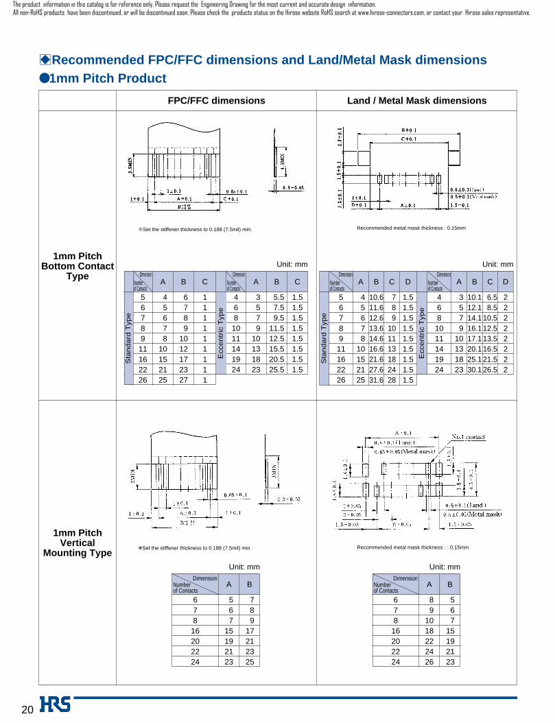
BRecommended FPC/FFC dimensions and Land/Metal Mask dimensions● 1mm Pitch Product
Land / Metal Mask dimensionsFPC/FFC dimensions
1mm PitchBottom Contact
Type
1mm PitchVertical
Mounting Type
πSet the stiffener thickness to 0.188 (7.5mil) min.
Recommended metal mask thickness : : 0.15mm
56789
11162226
040506070810152125
060708091012172327
111111111
468
1011141924
0305070910131823
05.507.509.511.512.515.520.525.5
1.51.51.51.51.51.51.51.5
DimensionNumberof Contacts
A B CDimension
Numberof Contacts
A B C
Unit: mm
678
16202224
05060715192123
07080917212325
DimensionNumberof Contacts
A B
Unit: mm
678
16202224
08091018222426
05060715192123
DimensionNumberof Contacts
A B
Unit: mm
*Set the stiffener thickness to 0.188 (7.5mil) min.
56789
11162226
040506070810152125
10.611.612.613.614.616.621.627.631.6
070809101113182428
468
1011141924
0305070910131823
10.112.114.116.117.120.125.130.1
06.508.510.512.513.516.521.526.5
DimensionNumberof Contacts
A B CDimension
Numberof Contacts
A B C
1.51.51.51.51.51.51.51.51.5
22222222
D D
Unit: mm
Sta
nd
ard
Typ
e
Ecc
en
tric
Typ
e
Ecc
en
tric
Typ
e
Sta
nd
ard
Typ
e
Recommended metal mask thickness : 0.15mm
The product information in this catalog is for reference only. Please request the Engineering Drawing for the most current and accurate design information.All non-RoHS products have been discontinued, or will be discontinued soon. Please check the products status on the Hirose website RoHS search at www.hirose-connectors.com, or contact your Hirose sales representative.

21
Note: 2,000 pieces per reel.
Unit:mm
BPackaging SpecificationEmbossed Carrier Tape DimensionsHorizontal Type (Common to Bottom/Top Contact, 0.5mm/1mm Pitch)
ADimension
Numberof Contacts
16
16
16
24
24
24
24
24
24
24
24
24
24
24
6
10
11
12
13
14
15
16
17
18
19
20
22
24
B
----------
----------
----------
----------
----------
----------
----------
----------
----------
----------
----------
----------
----------
----------
C
07.5
07.5
07.5
11.5
11.5
11.5
11.5
11.5
11.5
11.5
11.5
11.5
11.5
11.5
D
16.5
16.5
16.5
24.5
24.5
24.5
24.5
24.5
24.5
24.5
24.5
24.5
24.5
24.5
ADimension
Numberof Contacts
24
24
32
32
32
32
32
32
44
44
44
44
44
44
25
26
28
29
30
32
33
34
36
40
42
45
50
53
B
----------
----------
28.4
28.4
28.4
28.4
28.4
28.4
40.4
40.4
40.4
40.4
40.4
40.4
C
11.5
11.5
14.2
14.2
14.2
14.2
14.2
14.2
20.2
20.2
20.2
20.2
20.2
20.2
D
24.5
24.5
32.5
32.5
32.5
32.5
32.5
32.5
44.5
44.5
44.5
44.5
44.5
44.5
Note: 2,000 pieces per reel.
Unit:mm
ADimension
Numberof Contacts
16
24
24
24
24
32
44
44
4
6
8
10
11
14
19
24
Ecc
entr
icT
ype
B
----------
----------
----------
----------
----------
28.4
40.4
40.4
C
07.5
11.5
11.5
11.5
11.5
14.2
20.2
20.2
D
16.5
24.5
24.5
24.5
24.5
32.5
44.5
44.5
● 1mm Pitch Bottom Contact Type
● 0.5mm Pitch Bottom/Top Contact Type
Sta
ndar
dT
ype
ADimension
Numberof Contacts
16
24
24
24
24
24
32
44
44
5
6
7
8
9
11
16
22
26
B
----------
----------
----------
----------
----------
----------
28.4
40.4
40.4
C
07.5
11.5
11.5
11.5
11.5
11.5
14.2
20.2
20.2
D
16.5
24.5
24.5
24.5
24.5
24.5
32.5
44.5
44.5
(2.0)Flat surface for placement with Automatic equipment
The product information in this catalog is for reference only. Please request the Engineering Drawing for the most current and accurate design information.All non-RoHS products have been discontinued, or will be discontinued soon. Please check the products status on the Hirose website RoHS search at www.hirose-connectors.com, or contact your Hirose sales representative.

22
Note: 1,000 pieces per reel.
Note: 1,000 pieces per reel.
Unit:mm
Vertical Mounting Type (Common to 0.5mm/1mm Pitch)
ADimension
Numberof Contacts
16
16
24
24
24
24
24
24
24
24
10
12
13
15
16
17
18
20
22
24
B
----------
----------
----------
----------
----------
----------
----------
----------
----------
----------
C
07.5
07.5
11.5
11.5
11.5
11.5
11.5
11.5
11.5
11.5
D
16.5
16.5
24.5
24.5
24.5
24.5
24.5
24.5
24.5
24.5
ADimension
Numberof Contacts
24
24
24
32
44
44
44
6
7
8
16
20
22
24
B
----------
----------
----------
28.4
40.4
40.4
40.4
C
11.5
11.5
11.5
14.2
20.2
20.2
20.2
D
24.5
24.5
24.5
32.5
44.5
44.5
44.5
ADimension
Numberof Contacts
24
32
32
32
44
44
44
44
44
44
56
26
30
32
33
34
36
40
45
49
50
60
B
----------
28.4
28.4
28.4
40.4
40.4
40.4
40.4
40.4
40.4
52.4
C
11.5
14.2
14.2
14.2
20.2
20.2
20.2
20.2
20.2
20.2
26.2
D
24.5
32.5
32.5
32.5
44.5
44.5
44.5
44.5
44.5
44.5
56.5
● 1mm Pitch Vertical mounting Type
● 0.5mm Pitch Vertical mounting Type
Unit:mm
(1.75)Flat surface for placement with Automatic equipment
The product information in this catalog is for reference only. Please request the Engineering Drawing for the most current and accurate design information.All non-RoHS products have been discontinued, or will be discontinued soon. Please check the products status on the Hirose website RoHS search at www.hirose-connectors.com, or contact your Hirose sales representative.

HRS test conditions
Solder method :Reflow, IR/hot air
(Nihon Den-netsu Co., Ltd.’s
Part Number: SENSBY NR-2)
Environment: :Room air
Solder composition :Paste, 63%Sn/37%Pb
(Senju Metal Industry, Co., Ltd.’s
Part Number: OZ63-201C-50-9)
Test board :Glass epoxy 40mm∞80mm∞1.6mm thick
Land dimensions :Top and bottom
contact type 0.3mm∞1.3mm
Vertical mounting type 0.6mm∞1.5mm
Metal mask :Top and bottom contact type
0.25mm∞1.3mm∞0.15mm thick
Vertical mounting type
0.5mm∞1.5mm∞0.15mm thick
This temperature profile is based on the above conditions.
In individual applications the actual temperature may vary,
depending on solder paste type, volume/thickness and board
size/thickness. Consult your solder paste and equipment
manufacturer for specific recommendations.
23
Reel Dimensions (Common to All Types)
BRecommended Temperature Profile
End portion Mounting portion Lead portion (400mm min.)
Top cover tapeBlank portion
(10 pockets min.)
Embossed carrier tapeBlank portion
(10 pockets min.)
The product information in this catalog is for reference only. Please request the Engineering Drawing for the most current and accurate design information.All non-RoHS products have been discontinued, or will be discontinued soon. Please check the products status on the Hirose website RoHS search at www.hirose-connectors.com, or contact your Hirose sales representative.

24
25
25
5
35
25
25
30
175
295
BFH12 Series FPC/FFC Construction (Recommended Specifications)
1. FFC FFC : Flexible Flat Cable
FPC : Flexible Printed Circuit
Material Name Material Thickness (µm)
2. FPC
3. Precautions
Material Name
Covering layer film
Cover adhesive
Surface treatment
Copper foil
Base adhesive
Base film
Reinforcement material adhesive
Stiffener
Material Thickness (µm)
1. This specification is a recommendation for the construction of the FH12 Series FPC and FFC (t=0.3 ±0.05).
2. For details about the construction, please contact the FPC/FFC manufacturers.
Note: Use of a thicker FFC results in a stiffer lock action and the lock is more easily released.
A factor that contributes to thicker FFC is the use of 250 µm stiffener which is thicker than the standard (188 µm) product. This
results in a total thickness of 357 µm.
When using FFC, control of FFC thickness becomes easy if you indicate to us the thickness of the stiffener.
*Real tolerance of thickness dimension is on the order of ±20 µm (275 to 315 µm)
35
30
12
30
188
295
Hard copper foil with tin plating
Adhesive
Polyester
Adhesive
Stiffener (Note)
Polyester type
Polyester type
Polyester type
Total
Polyamide 1 mil
Tin-lead
Cu 1oz
Polyamide 1 mil
Heat-hardened adhesive
Polyamide 7 mil
Total
The product information in this catalog is for reference only. Please request the Engineering Drawing for the most current and accurate design information.All non-RoHS products have been discontinued, or will be discontinued soon. Please check the products status on the Hirose website RoHS search at www.hirose-connectors.com, or contact your Hirose sales representative.
Top Related