


Languages
Pages
Legal

OFFSHORE TECHNOLOGYREPORT - OTO 2000 064
Wire Rope Non-Destructive Testing -Survey of Instrument Manufacturers
Date of Issue: September 2000 Project number 3560

This report is made available by the Health and Safety Executive aspart of a series of reports of work which has been supported by fundsprovided by the Executive. Neither the Executive, nor thecontractors concerned assume any liability for the reports nor do theynecessarily reflect the views or policy of the Executive.
Wire Rope Non-Destructive Testing -Survey of Instrument Manufacturers
Prepared by
The University of Reading

SUMMARY
This document reports a study to supplement the HSE project on Non-destructive testing of wire rope(Tytko, Chaplin & Ridge, 1999). The earlier study was undertaken in order to assess the reliability ofa limited number of different sets of wire rope non-destructive testing equipment in terms of identifyingand quantifying rope degradation (wire breaks; abrasive wear; plastic wear; corrosion and slack wires).
The results from the earlier project indicated the confidence which might be placed in NDT technologywhen quantifying for different rope constructions, categories of defect appropriate to typical uses, i.e.the minimum level of defect which can be detected and the reliability with which the degradation can bequantified.
This study has identified 26 NDT companies, of which seven were selected for a more detailed review,and who were asked to complete questionnaires concerning operation of both NDT sensor heads and theassociated recording electronics. The companies chosen represent a wide range of technologies andnationalities, providing equipment designed for a range of rope applications, and are considered likelyto include all those which might be used in the UK.
There is a limited range of wire rope NDT instruments which are likely to be used in the UK, however,there are no agreed performance specifications for such instruments. It is essential that the operator ofthe NDT device understands the principles of operation of that particular device and is familiar with thelimitations of the equipment.
This is especially true of the calibration processes, which need to be understood especially in relation towhether “static” or “dynamic”. NDT operators need to be aware of other influences (such as ropetension or external magnetic fields) which can affect calibration. The level of understanding requiredfor effective and reliable rope inspection assisted by NDT goes beyond the initial guidance, as to its useand operation, given in instructions provided by the instrument manufacturers.
Wire Rope NDT - Survey of instrument manufacturers
iii
CONTENTS
10Laboratory Roman Martyna (LRM), Poland3.14
10Kanatop Electro-Mech. Plant, Ukraine3.13
10Intron Plus, Russia3.12
10Hitachi Building System Eng. and Service, Japan3.11
9Heath & Sherwood3.10
9Halec SA, France3.9
9ETH Zurich, Switzerland3.8
9Kündig SA, Switzerland3.7
8Druk Pak AG/EMSA, Switzerland/Holland3.6
8Dr Brandt, Germany3.5
8DMT, Germany3.4
8British Coal, Great Britain3.3
8AATS Anglo American plc. group, South Africa3.2
8AGH, Poland3.1
7NDT EQUIPMENT MANUFACTURING COMPANIES/ORGANISATIONS3
6Types of sensors in use2.4
5Types of magnets in use2.3
4Considerations relevant to LMA measurement2.2
3Considerations relevant to local fault measurement2.1
2NDT TECHNOLOGY - PRINCIPLES OF OPERATION2.
1INTRODUCTION1.
viLIST OF TABLES
viLIST OF FIGURES
iiiSUMMARY
Wire Rope NDT - Survey of instrument manufacturers
iv
25REFERENCES7
23ACKNOWLEDGEMENTS6
22DISCUSSIONS AND CONCLUSIONS5
15COMPARISON OF THE EQUIPMENT SURVEYED4
14ZEG- Tytchy, Poland3.26
14Zawada NDT, Poland3.25
13Wire Rope Testers Inc., USA3.24
13VVUU, Czech Republic3.23
13TÜV UK Ltd., Germany3.22
13Technical University Stuttgart, Germany3.21
13Shanghai Maritime University, China3.20
12Rotesco, Canada3.19
12RAU - Dr. Swanepoel, South Africa3.18
11NDT Technologies, USA3.17
11Meraster, Poland3.16
10Lloyds Beal, Great Britain3.15
Wire Rope NDT - Survey of instrument manufacturers
v
LIST OF FIGURES
GP-2S magnetic sensor head and MD120 digital recorderFigure 3.7Computerised Rotescograph console model 2DFigure 3.6Rotresco sensor head R300-3 and console model 2C-TAG88MFigure 3.5NDT Technologies sensor head LMA 125 and CC-03 (rev.A) signal consoleFigure 3.4Ropescan sensor head and electronic setFigure 3.3A selection of Intron test headsFigure 3.2Magnograph ®II and data loggerFigure 3.1
Measured nominal LMA (left) and effective LMA (right) for a uniformlyabraded rope
Figure 2.3Typical LMA and Local Fault (LF) traces for a severely degraded ropeFigure 2.2Typical electromagnetic NDT headFigure 2.1
LIST OF TABLES
After sales service and supportTable 4.7Calibration and interpretation of the output signalTable 4.6Accuracy/SensitivityTable 4.5Computing requirementsTable 4.4Recording technologyTable 4.3Physical dimensions, size and weightTable 4.2Generic parameters of NDT equipment surveyedTable 4.1Main world producers of non -destructive magnetic wire rope test apparatusTable 3.1
Wire Rope NDT - Survey of instrument manufacturers
vi

1. INTRODUCTION
This document reports a study to supplement the HSE project, report number OTO 1999 032, onNon-destructive testing of wire rope (Tytko Chaplin & Ridge, 1999).
The earlier study was undertaken in order to assess the reliability of different sets of wire ropenon-destructive testing equipment in terms of identifying and quantifying rope degradation. To this enda set of four different rope constructions were selected which represented a broad range of ropes in usein the offshore environment. Lengths of these ropes had realistic damage artificially (and hencequantifiable) induced in them, before testing using the different sets of NDT equipment in otherwiseidentical test conditions. Defects investigated included wire breaks (both internal and external);abrasive wear; plastic wear; corrosion and slack wires.
The results from the earlier project indicated the confidence which might be placed in NDT technologywhen quantifying for different rope constructions, categories of defect appropriate to typical uses i.e.the minimum level of defect which can be detected and the reliability with which the degradation can bequantified.
This study has reviewed different sets of equipment which are available for use for the non-destructivetesting of wire ropes on a world-wide basis. Inevitably, the list will not be exhaustive, as there may becompanies of which the authors are not aware, or who have been founded since this report was written,however, they will be representative of the type of equipment currently available on the market. Thisreport lists twenty six companies who either design, manufacture or market NDT equipment (seesection 3).
Of the companies listed in section 3, seven were selected for a more detailed review, and were asked tocomplete questionnaires concerning operation of both the NDT sensor head and the associatedrecording electronics. The companies chosen represent a wide range of technologies and nationalities,providing equipment designed for a range of rope applications, and were considered likely to include allthose which might be used in the UK.
The following section describes the main principles of the operation of magnetic NDT equipment.Section 3 provides an overview of the different sets of equipment available, seven of which arereviewed more closely in Section 4, as mentioned above. Section 5 presents the discussion andconclusions of this study.
Wire Rope NDT - Survey of instrument manufacturers
1
2. NDT TECHNOLOGY - PRINCIPLES OF OPERATION
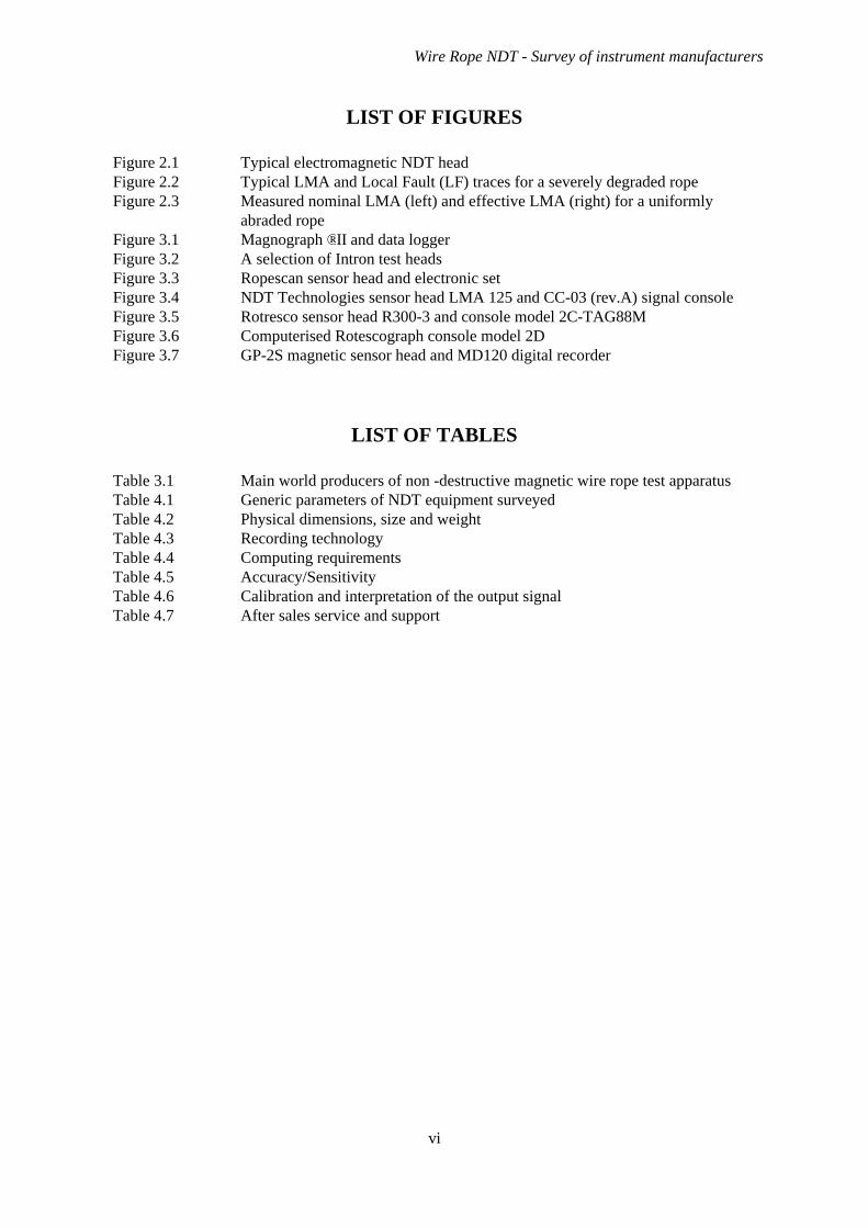
NDT devices for inspecting wire ropes have been in use for well over fifty years. The only reallyeffective technology that is in current use depends on the magnetic properties of the steel wire rope.The background to this technology has been described by Cordon (1988), Weischedel & Chaplin(1992), Chaplin & Smith (1993) and many other references which discuss the use of NDT equipment.(The proceedings from a recent conference in Kraków on the use of NDT contains papers indicating thestate of the art in many aspects of this technology (Chaplin ed., 1999). Wire rope NDT is usedextensively in the routine inspection of mine hoist ropes throughout the world. It is also used forinspecting both track and haulage ropes in rope-ways, particularly in mountain installations (cable carsand ski lifts). It is in the context of these applications, especially mining that the technology has beendeveloped. Increasing concern for establishing the long-term integrity of offshore ropes used in anumber of applications (particularly in mechanical handling equipment) has led to extension of this typeof rope NDT technology to the offshore industry.
The principles of operation for electromagnetic wire rope NDT systems employ:
w measurements of fringe fields near the surface of the rope to detect local defects such as brokenwires, corrosion pitting, local wear.
w measurements of changes in magnetic flux passing through a short length of rope to quantifychanges in metallic cross section.
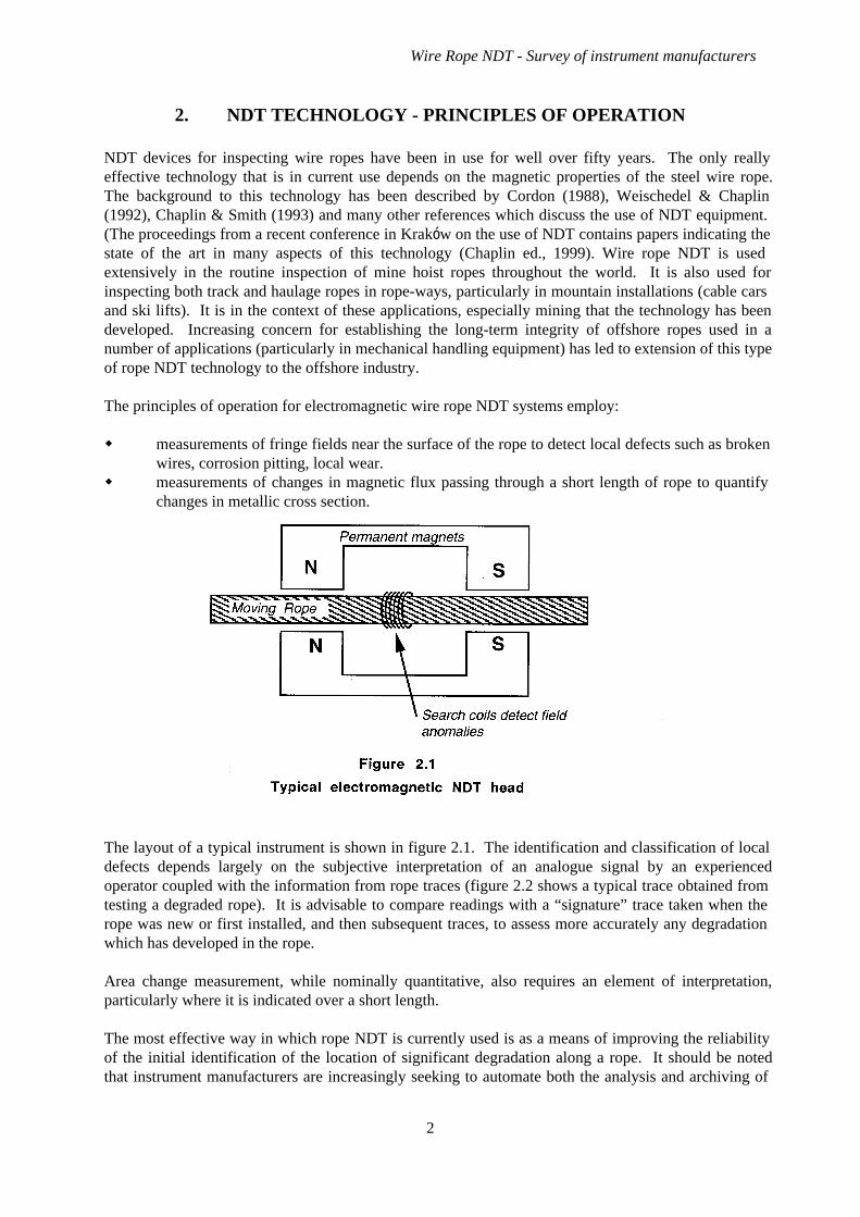
The layout of a typical instrument is shown in figure 2.1. The identification and classification of localdefects depends largely on the subjective interpretation of an analogue signal by an experiencedoperator coupled with the information from rope traces (figure 2.2 shows a typical trace obtained fromtesting a degraded rope). It is advisable to compare readings with a “signature” trace taken when therope was new or first installed, and then subsequent traces, to assess more accurately any degradationwhich has developed in the rope.
Area change measurement, while nominally quantitative, also requires an element of interpretation,particularly where it is indicated over a short length.
The most effective way in which rope NDT is currently used is as a means of improving the reliabilityof the initial identification of the location of significant degradation along a rope. It should be notedthat instrument manufacturers are increasingly seeking to automate both the analysis and archiving of
Wire Rope NDT - Survey of instrument manufacturers
2
the NDT trace. Recent developments have seen the use of custom designed electronics and customwritten software for use on proprietary computing equipment.
Regular NDT inspections provide a powerful tool in monitoring the rate of degradation of a rope.[Regulations for deep South African mine hoist systems require routine NDT at 3 month intervals,using equipment that has been certified as suitable, used by operators qualified as competent (SABS0293:1996).] Under consistent conditions a rope in perfect conditions will show a trace that is areproducible “signature” determined by its complex helical structure. The quality of a trace isimproved by avoiding vibration and maintaining a steady speed (these considerations are much moreimportant that maintaining a high speed).
Rope NDT is especially valuable in aiding the rope examiner when inspecting a long rope which iscovered in heavy grease or marine growth. However, the technology has not yet reached the stage ofdevelopment where the acceptance or rejection of a rope can be automated. However the underwaterinspection of rope using a remotely controlled NDT system is feasible (Bavins, 1988 and NobleDenton, 1996). For conventional six strand ropes, the NDT evidence can be supported by video ofdamage locations; for spiral strand constructions with polymer sheathing, the protection from corrosionwill provide a “clean” signal that will be easier to interpret. More sophisticated computerised analysisof signals will also enhance comparison of subsequent signals.
Development of rope NDT systems to provide more detailed information will be motivated by the needfor interpretation of signal without visual back-up. This involves simple development, not innovation.
2.1 CONSIDERATIONS RELEVANT TO LOCAL FAULT (LF) MEASUREMENT
The distance along the rope over which local faults influence the external field, is usually such that wirebreaks which are close together cannot be differentiated explicitly. This “spatial sensitivity” variesbetween different instruments. The effect is a particular problem when wire breaks are internal; forexample in a multi-strand rope with hundreds of internal breaks per metre, the effect on the trace tendsto seem just a magnification of the new rope signature.
Most instruments cannot give any indication of the distribution of wire breaks around the rope. Sincethere is a considerable difference between the effects of the same number of breaks concentrated in onestrand, as opposed to uniformly distributed, this is an important limitation, but can be easily overcomewhen visual inspection can complement the NDT.
Wire Rope NDT - Survey of instrument manufacturers
3

Recently, work has been reported from the University of Stuttgart into the development of a test headwhich has an annular array of two sets of 30 Hall effect sensors (Nussbaum, 1999). This system incombination with computerised processing of the data can provide a graphical representation of strayfield around and along the rope which can separate closely spaced wire breaks.
2.2 CONSIDERATIONS RELEVANT TO LMA MEASUREMENT
A measurement of the changes in the total flux passing through the rope can provide a quantitativeindication of changes in metallic cross section area. A variety of different techniques has beendeveloped by designers of rope NDT devices for making this measurement. The most significant effectof these differences in technology relate to the threshold length over which these area changes areindicated accurately. This threshold length can vary from as little as 10 mm to 750 mm. The effect ofdifferences in threshold length will be to have a significant impact on the performance of differentinstruments. It can be seen in figure 2.2, by looking at the LMA trace, that the LMA sensors maydetect local faults. However, unless the air gap between local faults is long enough (and this thresholdlength is dependent upon the instrument in use) the true value of LMA will be attenuated (Tytko et al.,1999).
Area loss signal changes with the saturation flux density of steel. As a result, LMA signal can changewith rope tension. So in situations (such as deep water mooring) where tension will change along therope, an allowance may be necessary for this effect.
One problem that the manufacturers of rope NDT devices have not been addressing is that ofcalibration using realistic degradation. This relates particularly to the problem of interpretation of arealoss measurements. Current methods of calibration involve using steel rods or wires drawn through thedevice alongside the rope: this provides an absolute measure of area loss signal, but has no relationshipto the nature of area loss as it would be distributed in a used rope. This procedure is further questionedas the LMA sensitivity of some instruments is affected by rope motion. A static calibration in whichthe rod is withdrawn from alongside a stationary rope gives a different response to a calibration inwhich the rod is attached to a moving rope (Golosinski & Tytko, 1998).
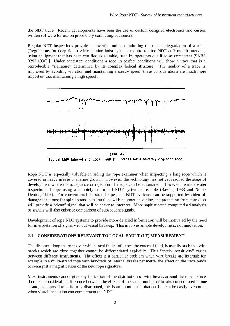
Wear or corrosion never affects individual wires uniformly along their length. A typical distribution ina crane or mooring rope would involve concentration in outer wires where they come to the crownposition on the outer strands. Under these conditions the rope examiner is interested in the cumulativeeffect of the degradation to all outer wires. Manufacturers of NDT instruments are unable to indicatewhether this cumulative effect is what their instruments will measure, or whether the value recordedrelates to a cross-section “snapshot” measurement (figure 2.3). The earlier work in this study hasindicated that NDT equipment gives a measurement of the “snapshot” area, rather than the criticaleffective area (Tytko et al., 1999 and Chaplin et al., 1999).
Wire Rope NDT - Survey of instrument manufacturers
4
2.3 TYPES OF MAGNETS IN USE
Various means have been used over the years to magnetise ropes, which include:
w permanent magnets;w a direct current passing through circumferential coils;w an alternating current passing through circumferential coils.
The first of these three methods requires that the permanent magnets provide sufficient flux passingthrough the section of rope (being inspected) effectively to saturate the steel. This ensures that the fluxassociated with local defects is displaced outside the rope where it can be detected (rather thandisplaced into adjacent wires, where the effect will go unnoticed). Direct current magnetisation systemsoperate on the same principle of saturation, and have only been used by a few instrumentmanufacturers, when it was perceived that permanent magnets could not generate sufficient flux. TheDC electromagnet systems are no longer relevant due to the availability of much more powerfulpermanent magnets than in the past. Although permanent magnets (and especially permanent rare earthmagnets such as Neodymium-Iron-Boron (Nd-Fe-B) or Samarium-Cobalt) are more costly than DCelectromagnet systems, they enable a lighter system to be employed than one using heavy lead/acidbatteries.
Alternating current systems, which essentially employ the rope as the core of a transformer, werefavoured for inspecting triangular strand mine hoist ropes used in the very deep shafts of South Africangold mines. The South African technology for these AC instruments became highly developed, but isnow being overtaken and displaced by permanent magnet systems.
Realistically systems which will be most commonly encountered are those NDT test heads which usepermanent magnets.
2.4 TYPES OF SENSORS IN USE
Although there has been a trend towards acceptance of permanent rare earth magnets as the best formof magnetising the rope, there is a wide range of sensors employed by various manufacturers foridentifying local faults and quantifying area changes including:
Wire Rope NDT - Survey of instrument manufacturers
5

w circumferential coils;w saddle coils;w return flux coils;w “flux gate” coils;w Hall effect sensors in various locations.
Coils in use with a steady magnetising flux have the disadvantage that the current generated isproportional to the speed of the rope passing through the measuring head. This problem is overcome inthe electronic signal processing by attenuating the system gain in proportion to speed, but consequentlythere is a minimum speed below which the attenuation is inoperative and the signal suffers inconsequence. Typical minimum speeds are in the region of 0.25 to 0.5 m/sec. Lower speeds may beaccommodated through modifications to the electronic system. Hall effect devices, which generate acurrent proportional to the intersected flux, are speed insensitive and can therefore operate down to verylow speeds, but require some subtle magnetic circuit design to be certain to capture the stray field. Halleffect sensors may also be more expensive and historically have been less stable than coil basedsystems.
Another potential problem area relates to the integration of signals from coils when computing loss ofarea. Historically this has depended upon analogue integrator circuits requiring high long term stabilityto ensure that drift does not influence the signal. Digital signal processing (DSP) offers an alternativeroute which might be an advantage here. In systems which facilitate transfer of the NDT signal to acomputer a range of other advances have been introduced. These typically include archiving andretrieval of signals (which can be advantageous for making comparisons of new and old traces), as wellas allowing expansion of segments of trace of particular interest. Processing of the signal can alsoyield benefits, but such procedures are not yet generally available. One category of such a developmentis the calculation of a single parameter to indicate rope acceptance or discard (Hamelin et al., 1997).Although presenting the advantages of simplicity, this approach is considered by many to be unsuitablefor any but “standard” conditions. Other developments include the possibility of signal processing toextract additional information such as using a “rolling” Fourier transform technique to extractinformation on rope lay length (Tytko & Golosinski, 1998). Developments at the Technical Universityof Stuttgard have lead to a prototype instrument which captures the signals from an array of Hallsensors distributed around the rope which provides a map of magnetic field anomalies plotted over theunwrapped surface of the rope (see also Section 3.21) facilitating separation of closely spaced internalwire breaks.
The various combinations of these different sensors and magnetising methods have resulted in thetechnology becoming a patent lawyer’s delight. The current lack of any standards for qualification ofequipment or operators has also lead to a degree of confusion, although this situation is changing by theintroduction of quantitative standards on this subject in the USA (ASTM E1571-93); South Africa(Backeberg, 1993 and SABS 0293:1996); and, Poland (Hansel et al., 1992). Consequently there arenumerous devices manufactured, mostly by fairly small concerns, in some cases with restrictedavailability due to patent problems, and also with far from uniform performance (or methods fordefining and assessing performance).
However despite these apparent problems electromagnetic NDT is not only used for many ropeapplications, but is heavily relied upon when assessing the integrity of wire ropes and arriving atdiscard decisions in critical applications. The use of wire rope NDT is extending in terms of industries,countries and sophistication. However, the UK appears to be lagging somewhat behind in this area.
Wire Rope NDT - Survey of instrument manufacturers
6
3. NDT EQUIPMENT MANUFACTURINGCOMPANIES/ORGANISATIONS
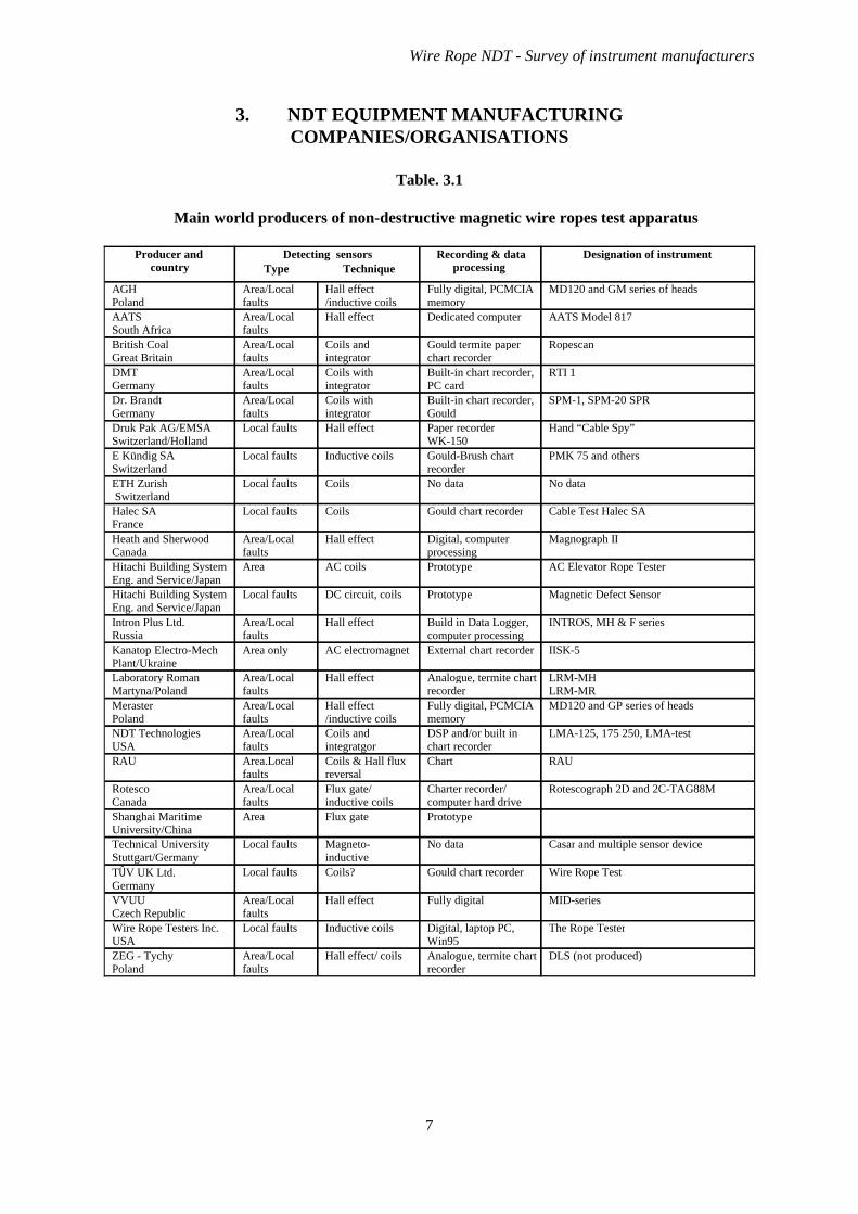
Table. 3.1
Main world producers of non-destructive magnetic wire ropes test apparatus
DLS (not produced)Analogue, termite chartrecorder
Hall effect/ coilsArea/Localfaults
ZEG - TychyPoland
The Rope TesterDigital, laptop PC,Win95
Inductive coilsLocal faults Wire Rope Testers Inc.USA
MID-seriesFully digitalHall effectArea/Localfaults
VVUUCzech Republic
Wire Rope TestGould chart recorderCoils?Local faultsTÛV UK Ltd.Germany
Casar and multiple sensor deviceNo dataMagneto-inductive
Local faultsTechnical UniversityStuttgart/Germany
PrototypeFlux gateAreaShanghai MaritimeUniversity/China
Rotescograph 2D and 2C-TAG88MCharter recorder/computer hard drive
Flux gate/inductive coils
Area/Localfaults
RotescoCanada
RAUChartCoils & Hall fluxreversal
Area.Localfaults
RAU
LMA-125, 175 250, LMA-testDSP and/or built inchart recorder
Coils andintegratgor
Area/Localfaults
NDT TechnologiesUSA
MD120 and GP series of headsFully digital, PCMCIAmemory
Hall effect/inductive coils
Area/Localfaults
MerasterPoland
LRM-MHLRM-MR
Analogue, termite chartrecorder
Hall effectArea/Localfaults
Laboratory RomanMartyna/Poland
IISK-5External chart recorderAC electromagnetArea onlyKanatop Electro-MechPlant/Ukraine
INTROS, MH & F seriesBuild in Data Logger,computer processing
Hall effectArea/Localfaults
Intron Plus Ltd.Russia
Magnetic Defect SensorPrototypeDC circuit, coilsLocal faultsHitachi Building SystemEng. and Service/Japan
AC Elevator Rope TesterPrototypeAC coilsAreaHitachi Building SystemEng. and Service/Japan
Magnograph IIDigital, computerprocessing
Hall effectArea/Localfaults
Heath and SherwoodCanada
Cable Test Halec SAGould chart recorderCoilsLocal faultsHalec SAFrance
No dataNo dataCoilsLocal faults ETH Zurish Switzerland
PMK 75 and othersGould-Brush chartrecorder
Inductive coilsLocal faultsE Kündig SASwitzerland
Hand “Cable Spy”Paper recorderWK-150
Hall effectLocal faultsDruk Pak AG/EMSASwitzerland/Holland
SPM-1, SPM-20 SPRBuilt-in chart recorder,Gould
Coils withintegrator
Area/Localfaults
Dr. BrandtGermany
RTI 1Built-in chart recorder,PC card
Coils withintegrator
Area/Localfaults
DMTGermany
RopescanGould termite paperchart recorder
Coils andintegrator
Area/Localfaults
British CoalGreat Britain
AATS Model 817Dedicated computerHall effectArea/Localfaults
AATSSouth Africa
MD120 and GM series of headsFully digital, PCMCIAmemory
Hall effect/inductive coils
Area/Localfaults
AGHPoland
TechniqueTypeDesignation of instrument Recording & data
processing Detecting sensorsProducer and
country
Wire Rope NDT - Survey of instrument manufacturers
7
3.1 AGH
See Zawada NDT, Poland*1
3.2 AATS (ANGLO AMERICAN PLC. GROUP) SOUTH AFRICA*
The AATS magnetic non-destructive rope testing equipment was developed against the background ofthe gold mining industry (AATS are a member of the Anglo American plc group). Wire rope forhoisting in the South African gold mines has been employed since late in the nineteenth century andNDT has been in use since early in the last century. The Anglo American Corporation as the largestmining house in South Africa has devoted considerable effort to ensuring that effective NDT systemsare available for the mines in which they have a controlling interest. This has become especiallysignificant with the moves to greater depth. The current development of shafts of 3000 m and morewill only be feasible with lower factors of safety. Operation at lower factors is only allowed withimproved winder control and rope inspection by qualified rope inspectors using validated NDTinstruments in combination with visual inspection.
Consequently, for a number of years, AATS have been developing their own NDT instruments,in-house, evaluating commercially available systems and sponsoring research and development in thefield. One particular development has been “in-situ” (i.e. permanently installed) NDT systems (Venter,1999). Two such systems are now operating and in each case are linked directly to the automatedwinder controller. The benefit of such a system is that the only major faults are really of interest, sincethe rope is being approved not for the next three months, but for the next few minutes.
The latest portable range of NDT heads which are surveyed in this report were developed from thisinitial “in-situ” system. The two systems have different ranges of performance, in that the smallerportable systems operator at a much lower maximum speed (2.5 m/s), they are however, more accuratein their measurement of LMA. Both the “in-situ” and “portable” test heads have in-house software forthe evaluation of the raw test data.
3.3 BRITISH COAL, GREAT BRITAIN
See Lloyds Beal*
3.4 DMT, GERMANY
No information available.
3.5 DR BRANDT, GERMANY
This company manufactures a range of testing equipment, one area of which is concerned with wireropes. The rope testing heads suitable for rope size up to Ø160 mm are available. Commercial testingis performed by WBK (Westfaelische Berggewerkschaetkasse Seilprüfstelle), Bochum, who alsocollaborate in instrument development. The special large diameter test head, which uses ferritemagnets, is very heavy at around 1000 kg!
3.6 DRUK PAK AG/EMSA, SWITZERLAND/HOLLAND
The “CABLESPY” was developed by the Swiss company, Druk Pak AG, and is intended for use oncranes, hoists, ropeways and similar lifting equipment, measuring only local faults. The test headswhich are suitable for ropes in the range Ø8 to Ø27 or Ø8 to Ø48 mm, are intended to be hand held and
Wire Rope NDT - Survey of instrument manufacturers
8
1 Companies which have been included in the fuller review in section 4 are marked with an asterix.
accordingly, the weight of the test heads is low, 3.7/6.5 kg respectively. The magnetisation flux ofthese instruments is inevitably much lower than most of their competitors.
3.7 KÜNDIG SA, SWITZERLAND
The development and operation of the Kündig test equipment is described in Kündig (1981). The PMKseries of testing heads has four sizes, for Ø40, Ø70, Ø90 and Ø110 ropes. This series of test heads isdesigned for local fault detection only.
3.8 ETH ZURICH, SWITZERLAND
No detailed information available, but in-house design and construction solely for their own use.
3.9 HALEC SA, FRANCE
Halec SA offers a range of structural integrity inspection services and testing techniques (Radiography,ultrasound and magnetic). Their main work with wire rope NDT covers a full range of fixed or movingrope applications (cableways, funiculars, lifts, mine hoists, bridges, chimneys).
3.10 HEATH & SHERWOOD, CANADA*
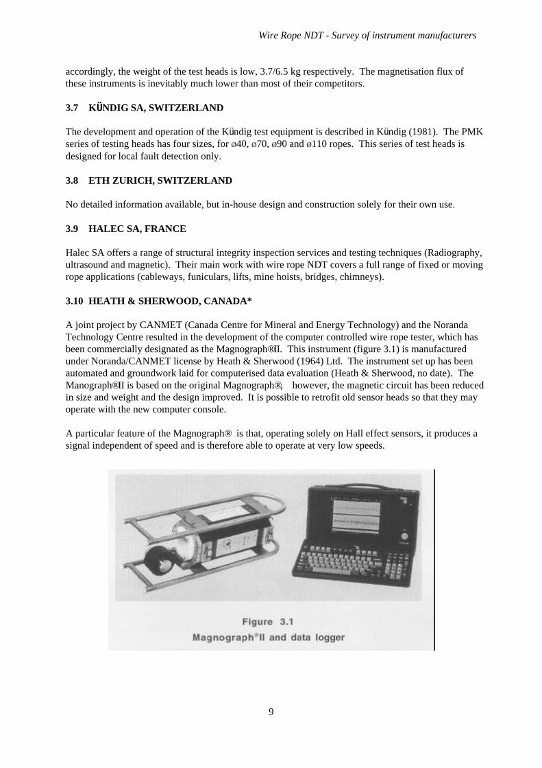
A joint project by CANMET (Canada Centre for Mineral and Energy Technology) and the NorandaTechnology Centre resulted in the development of the computer controlled wire rope tester, which hasbeen commercially designated as the Magnograph®II. This instrument (figure 3.1) is manufacturedunder Noranda/CANMET license by Heath & Sherwood (1964) Ltd. The instrument set up has beenautomated and groundwork laid for computerised data evaluation (Heath & Sherwood, no date). TheManograph®II is based on the original Magnograph®, however, the magnetic circuit has been reducedin size and weight and the design improved. It is possible to retrofit old sensor heads so that they mayoperate with the new computer console.
A particular feature of the Magnograph® is that, operating solely on Hall effect sensors, it produces asignal independent of speed and is therefore able to operate at very low speeds.
Wire Rope NDT - Survey of instrument manufacturers
9
The Magnograph® technology has been applied to a new version named PermaScan, which is aimed atpermanent installations in mines, for on demand monitoring of hoist ropes. The PermaScan isundergoing field trials at time of writing and is not yet commercially available (Hamelin, Hofmeister &Leung, 1999).
3.11 HITACHI BUILDING SYSTEM ENG. AND SERVICE, JAPAN
No information available.
3.12 INTRON PLUS LTD., RUSSIA*
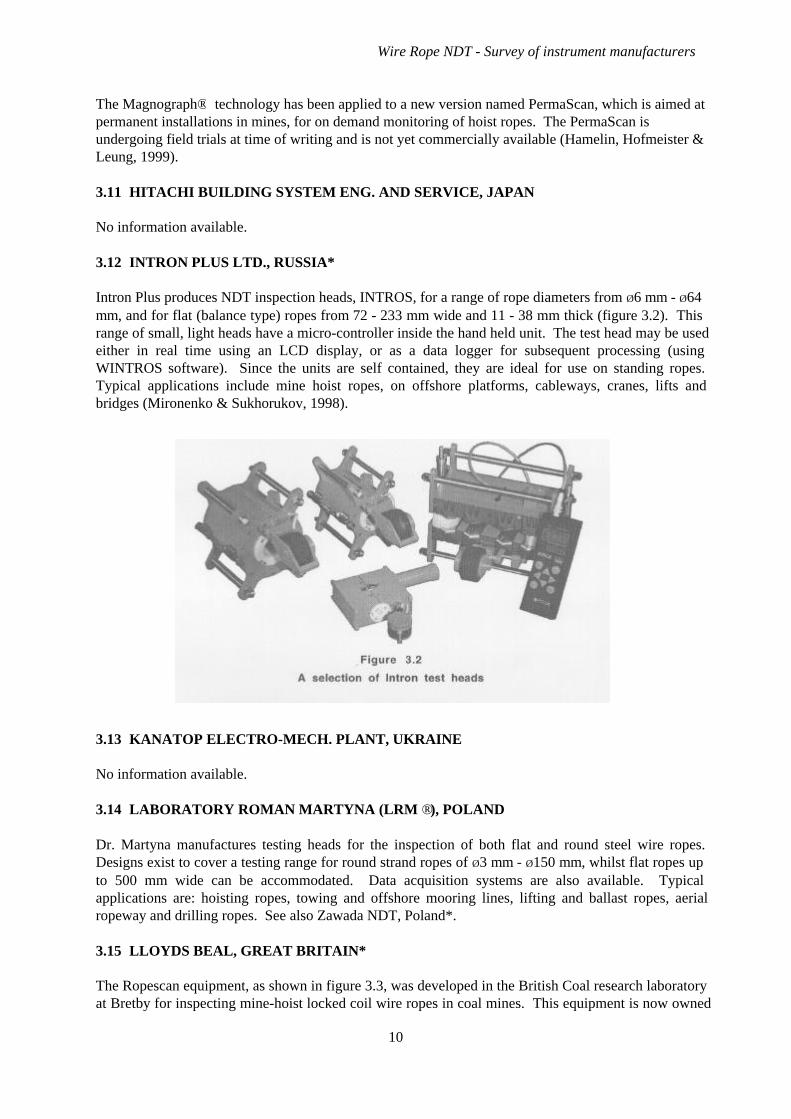
Intron Plus produces NDT inspection heads, INTROS, for a range of rope diameters from Ø6 mm - Ø64mm, and for flat (balance type) ropes from 72 - 233 mm wide and 11 - 38 mm thick (figure 3.2). Thisrange of small, light heads have a micro-controller inside the hand held unit. The test head may be usedeither in real time using an LCD display, or as a data logger for subsequent processing (usingWINTROS software). Since the units are self contained, they are ideal for use on standing ropes.Typical applications include mine hoist ropes, on offshore platforms, cableways, cranes, lifts andbridges (Mironenko & Sukhorukov, 1998).
3.13 KANATOP ELECTRO-MECH. PLANT, UKRAINE
No information available.
3.14 LABORATORY ROMAN MARTYNA (LRM ®), POLAND
Dr. Martyna manufactures testing heads for the inspection of both flat and round steel wire ropes.Designs exist to cover a testing range for round strand ropes of Ø3 mm - Ø150 mm, whilst flat ropes upto 500 mm wide can be accommodated. Data acquisition systems are also available. Typicalapplications are: hoisting ropes, towing and offshore mooring lines, lifting and ballast ropes, aerialropeway and drilling ropes. See also Zawada NDT, Poland*.
3.15 LLOYDS BEAL, GREAT BRITAIN*
The Ropescan equipment, as shown in figure 3.3, was developed in the British Coal research laboratoryat Bretby for inspecting mine-hoist locked coil wire ropes in coal mines. This equipment is now owned
Wire Rope NDT - Survey of instrument manufacturers
10
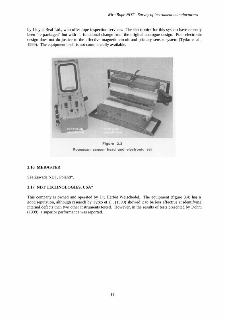
by Lloyds Beal Ltd., who offer rope inspection services. The electronics for this system have recentlybeen “re-packaged” but with no functional change from the original analogue design. Poor electronicdesign does not do justice to the effective magnetic circuit and primary sensor system (Tytko et al.,1999). The equipment itself is not commercially available.
3.16 MERASTER
See Zawada NDT, Poland*.
3.17 NDT TECHNOLOGIES, USA*
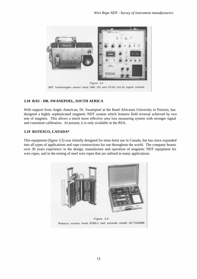
This company is owned and operated by Dr. Herbet Weischedel. The equipment (figure 3.4) has agood reputation, although research by Tytko et al., (1999) showed it to be less effective at identifyinginternal defects than two other instruments tested. However, in the results of tests presented by Dohm(1999), a superior performance was reported.
Wire Rope NDT - Survey of instrument manufacturers
11
3.18 RAU - DR. SWANEPOEL, SOUTH AFRICA
With support from Anglo American, Dr. Swanepoel at the Rand Africaans University in Pretoria, hasdesigned a highly sophisticated magnetic NDT system which features field reversal achieved by twosets of magnets. This allows a much more effective area loss measuring system with stronger signaland consistent calibration. At present, it is only available in the RSA.
3.19 ROTESCO, CANADA*
This equipment (figure 3.5) was initially designed for mine hoist use in Canada, but has since expandedinto all types of applications and rope constructions for use throughout the world. The company boastsover 30 years experience in the design, manufacture and operation of magnetic NDT equipment forwire ropes, and in the testing of steel wire ropes that are utilised in many applications.
Wire Rope NDT - Survey of instrument manufacturers
12
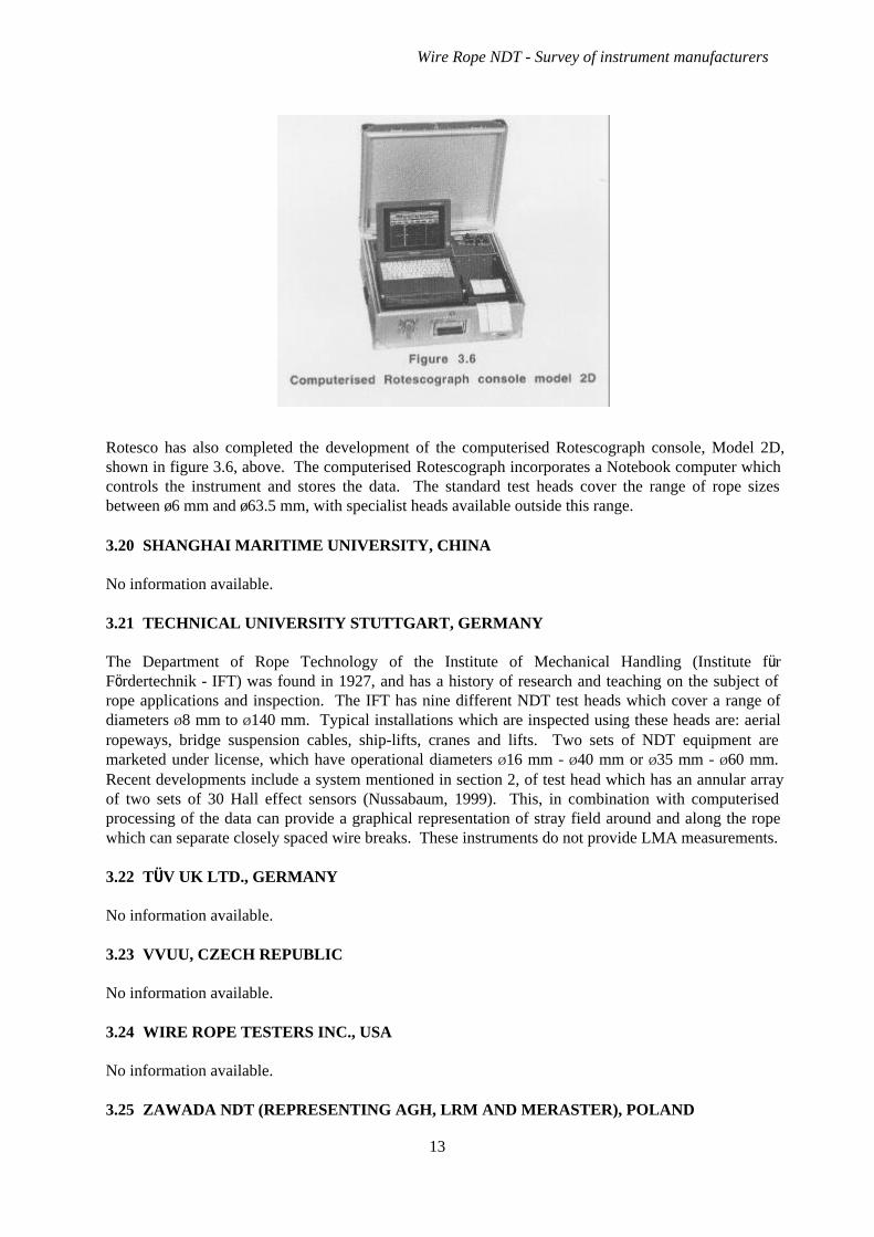
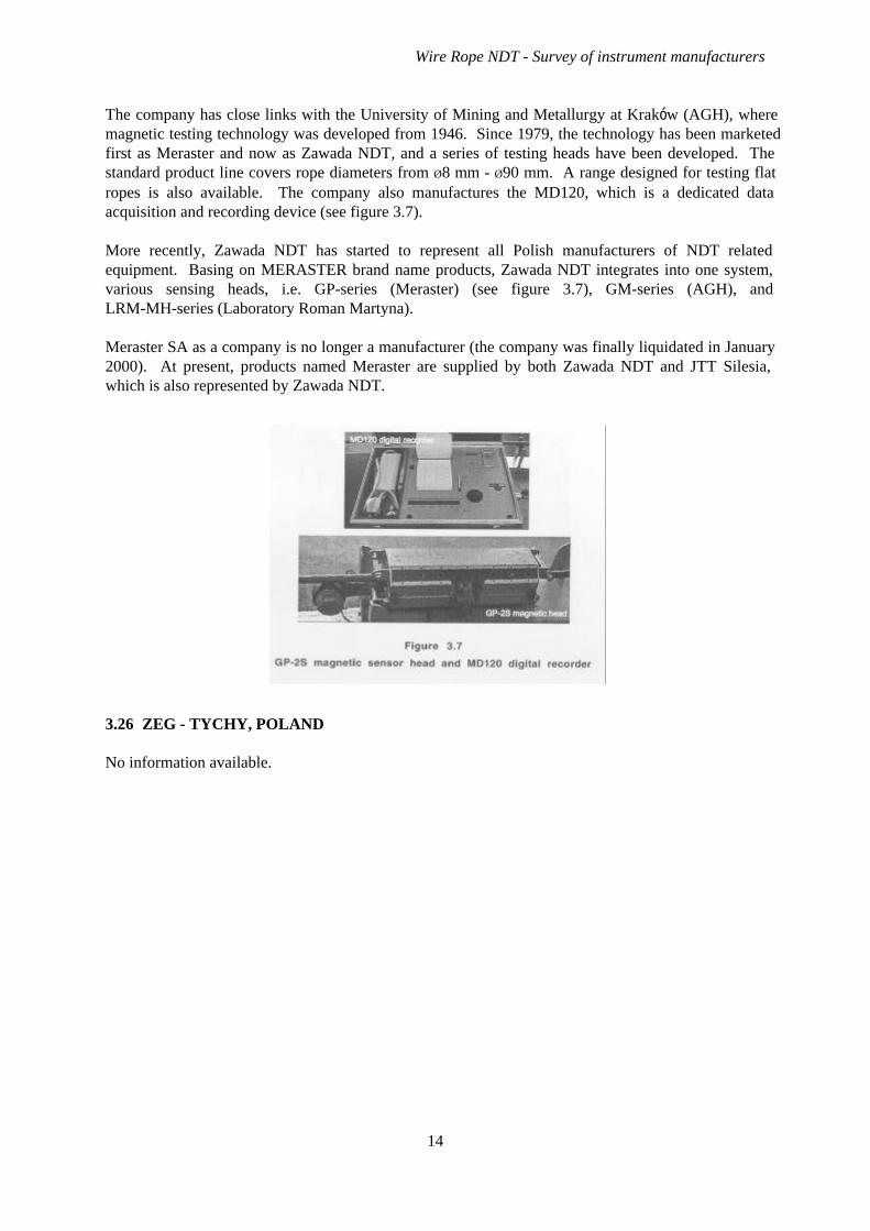
Rotesco has also completed the development of the computerised Rotescograph console, Model 2D,shown in figure 3.6, above. The computerised Rotescograph incorporates a Notebook computer whichcontrols the instrument and stores the data. The standard test heads cover the range of rope sizesbetween ø6 mm and ø63.5 mm, with specialist heads available outside this range.
3.20 SHANGHAI MARITIME UNIVERSITY, CHINA
No information available.
3.21 TECHNICAL UNIVERSITY STUTTGART, GERMANY
The Department of Rope Technology of the Institute of Mechanical Handling (Institute fürFördertechnik - IFT) was found in 1927, and has a history of research and teaching on the subject ofrope applications and inspection. The IFT has nine different NDT test heads which cover a range ofdiameters Ø8 mm to Ø140 mm. Typical installations which are inspected using these heads are: aerialropeways, bridge suspension cables, ship-lifts, cranes and lifts. Two sets of NDT equipment aremarketed under license, which have operational diameters Ø16 mm - Ø40 mm or Ø35 mm - Ø60 mm.Recent developments include a system mentioned in section 2, of test head which has an annular arrayof two sets of 30 Hall effect sensors (Nussabaum, 1999). This, in combination with computerisedprocessing of the data can provide a graphical representation of stray field around and along the ropewhich can separate closely spaced wire breaks. These instruments do not provide LMA measurements.
3.22 TÜV UK LTD., GERMANY
No information available.
3.23 VVUU, CZECH REPUBLIC
No information available.
3.24 WIRE ROPE TESTERS INC., USA
No information available.
3.25 ZAWADA NDT (REPRESENTING AGH, LRM AND MERASTER), POLAND
Wire Rope NDT - Survey of instrument manufacturers
13
The company has close links with the University of Mining and Metallurgy at Kraków (AGH), wheremagnetic testing technology was developed from 1946. Since 1979, the technology has been marketedfirst as Meraster and now as Zawada NDT, and a series of testing heads have been developed. Thestandard product line covers rope diameters from Ø8 mm - Ø90 mm. A range designed for testing flatropes is also available. The company also manufactures the MD120, which is a dedicated dataacquisition and recording device (see figure 3.7).
More recently, Zawada NDT has started to represent all Polish manufacturers of NDT relatedequipment. Basing on MERASTER brand name products, Zawada NDT integrates into one system,various sensing heads, i.e. GP-series (Meraster) (see figure 3.7), GM-series (AGH), andLRM-MH-series (Laboratory Roman Martyna).
Meraster SA as a company is no longer a manufacturer (the company was finally liquidated in January2000). At present, products named Meraster are supplied by both Zawada NDT and JTT Silesia,which is also represented by Zawada NDT.
3.26 ZEG - TYCHY, POLAND
No information available.
Wire Rope NDT - Survey of instrument manufacturers
14
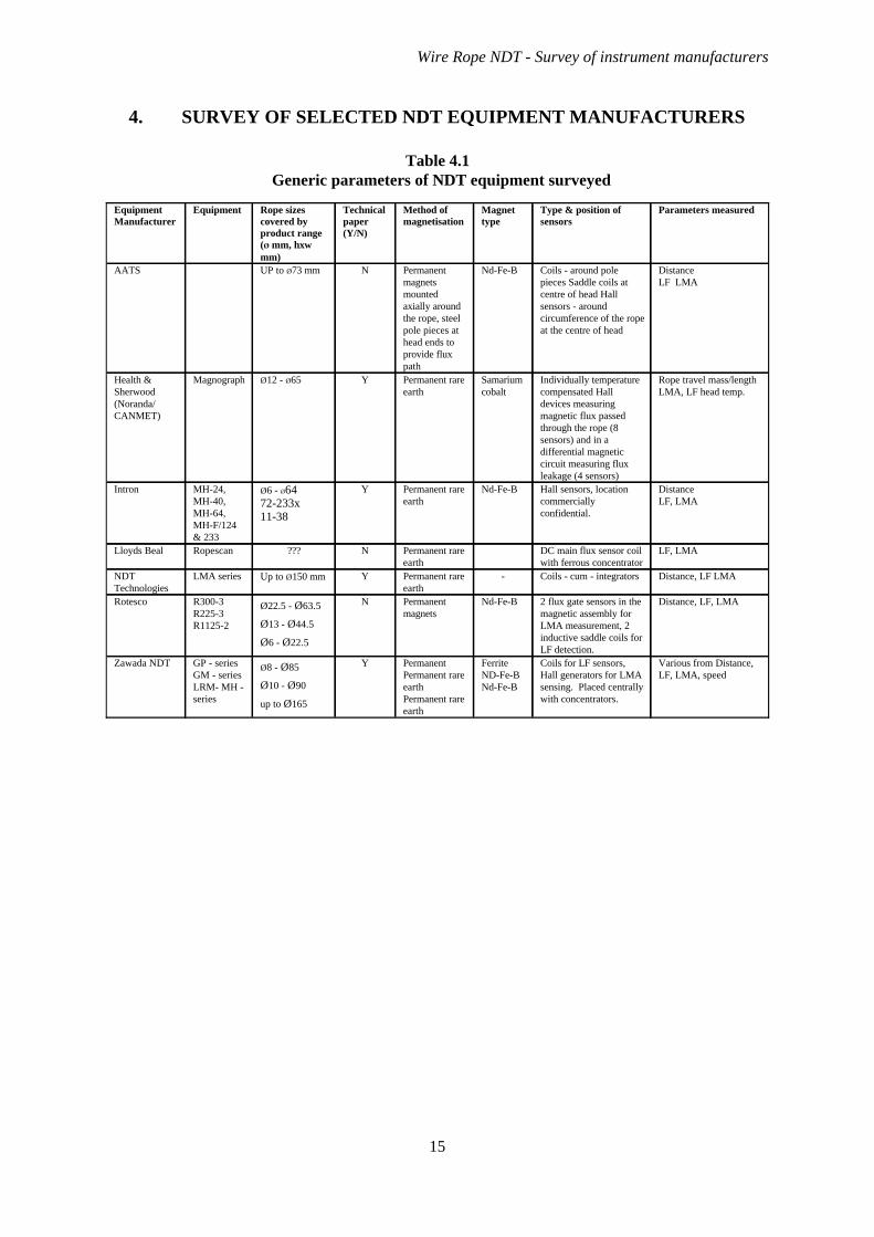
4. SURVEY OF SELECTED NDT EQUIPMENT MANUFACTURERS
Table 4.1Generic parameters of NDT equipment surveyed
Various from Distance,LF, LMA, speed
Coils for LF sensors,Hall generators for LMAsensing. Placed centrallywith concentrators.
FerriteND-Fe-BNd-Fe-B
PermanentPermanent rareearthPermanent rareearth
YØ8 - Ø85
Ø10 - Ø90
up to Ø165
GP - seriesGM - seriesLRM- MH -series
Zawada NDT
Distance, LF, LMA2 flux gate sensors in themagnetic assembly forLMA measurement, 2inductive saddle coils forLF detection.
Nd-Fe-BPermanentmagnets
NØ22.5 - Ø63.5
Ø13 - Ø44.5
Ø6 - Ø22.5
R300-3R225-3R1125-2
Rotesco
Distance, LF LMACoils - cum - integrators-Permanent rareearth
YUp to Ø150 mmLMA seriesNDTTechnologies
LF, LMADC main flux sensor coilwith ferrous concentrator
Permanent rareearth
N???RopescanLloyds Beal
DistanceLF, LMA
Hall sensors, locationcommerciallyconfidential.
Nd-Fe-BPermanent rareearth
YØ6 - Ø6472-233x11-38
MH-24,MH-40,MH-64,MH-F/124& 233
Intron
Rope travel mass/lengthLMA, LF head temp.
Individually temperaturecompensated Halldevices measuringmagnetic flux passedthrough the rope (8sensors) and in adifferential magneticcircuit measuring fluxleakage (4 sensors)
Samariumcobalt
Permanent rareearth
YØ12 - Ø65MagnographHealth &Sherwood(Noranda/CANMET)
Distance LF LMA
Coils - around polepieces Saddle coils atcentre of head Hallsensors - aroundcircumference of the ropeat the centre of head
Nd-Fe-BPermanentmagnetsmountedaxially aroundthe rope, steelpole pieces athead ends toprovide fluxpath
NUP to Ø73 mmAATS
Parameters measuredType & position ofsensors
Magnettype
Method ofmagnetisation
Technicalpaper(Y/N)
Rope sizescovered byproduct range(Ø mm, hxwmm)
EquipmentEquipmentManufacturer
Wire Rope NDT - Survey of instrument manufacturers
15
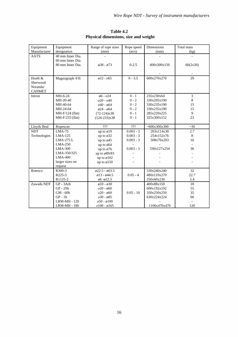
Table 4.2Physical dimensions, size and weight
18553566-
120
400x88x150600x192x192350x250x250630x224x224
-1100x470x470
0.05 - 10
ø10 - ø30Ø20 - ø60Ø20 - ø60Ø30 - ø85
Ø50 - ø100Ø100 - ø165
GP - 3ArhGP - 2ShGM - 60hGP - 1hLRM-MH - 120LRM-MH - 180
Zawada NDT
3222.75.4
530x240x240480x110x270250x60x230
0.05 - 4ø22.5 - ø63.5ø13 - ø44.5ø6 -ø22.5
R300-3R225-3R1125-2
Rotesco
2.78
16-
36---
203x114x38254x152x76508x76x203
-330x127x254
---
0.003 - 30.003 - 30.003 - 3
-0.003 - 3
---
up to ø19up to ø32up to ø45up to ø64up to ø76
up to ø89/83up to ø102up to ø150
LMA-75LMA-125LMA-275 LLMA-250LMA-300LMA-350/325LMA-400larger sizes onrequest
NDTTechnologies
~30~600x300x300??????RopescanLloyds Beal
38
15159
23
235x230x64330x205x190330x235x190330x235x190285x220x225325x300x152
0 - 10 - 20 - 20 - 20 - 10 - 1
ø6 - Ø24Ø20 - Ø40Ø40 - ø64ø24 - ø64
(72-124)x38(124-233)x38
MH-6-24MH-20-40MH-40-64MH-24-64MH-F/124 (flat)MH-F/233 (flat)
Intron
29600x270x2700 - 3.5ø12 - Ø65Magnograph ® IIHeath &SherwoodNoranda/CANMET
-
60(2x30)
-
-
400x300x150
-
0-2.5
-
ø38 - ø73
_
40 mm Inner Dia.60 mm Inner Dia.80 mm Inner Dia.
AATS
Total mass(kg)
Dimensions(mm)
Rope speed(m/s)
Range of rope sizes(mm)
Equipmentdesignation
EquipmentManufacturer
Wire Rope NDT - Survey of instrument manufacturers
16
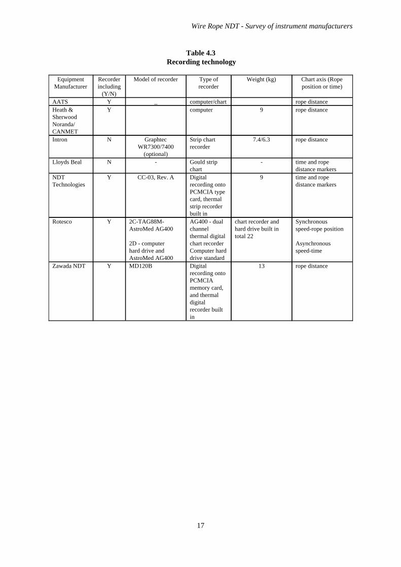
Table 4.3Recording technology
rope distance13Digitalrecording ontoPCMCIAmemory card,and thermaldigitalrecorder builtin
MD120BYZawada NDT
Synchronousspeed-rope position
Asynchronousspeed-time
chart recorder andhard drive built intotal 22
AG400 - dualchannelthermal digitalchart recorderComputer harddrive standard
2C-TAG88M-AstroMed AG400
2D - computerhard drive andAstroMed AG400
YRotesco
time and ropedistance markers
9Digitalrecording ontoPCMCIA typecard, thermalstrip recorderbuilt in
CC-03, Rev. AYNDTTechnologies
time and ropedistance markers
-Gould stripchart
-NLloyds Beal
rope distance7.4/6.3Strip chartrecorder
GraphtecWR7300/7400
(optional)
NIntron
rope distance9computerYHeath &SherwoodNoranda/CANMET
rope distancecomputer/chart_YAATS
Chart axis (Ropeposition or time)
Weight (kg)Type ofrecorder
Model of recorderRecorderincluding
(Y/N)
EquipmentManufacturer
Wire Rope NDT - Survey of instrument manufacturers
17

Table 4.4Computing requirements
486 or Pentium, Windows 95/98 or DOSoptions Interfacing hardware: PCMCIA/PC card slotSoftware supplied, depending on hardware
Zawada NDT
85 - 250 V AC, 47-63 Hz 250 VA max.Internal battery optional Connections for 12 VDC external battery
2D - Minimum requirements CPU - Pentium233MHz RAM-64 MBOperating system - DOS v5.0 plusWindows95Data Acquisition Hardware - NationalInstruments DAQPAD-1200
Rotesco
Batteries, battery chargerNotebook computer, MS Excel, A to Dconverter and data acquisition software,(NDS_CareTM Computer-Aided RopeEvaluation)
NDS Technologies???No output for data acquisitionLloyds Beal
3 AA rechargeable batteries, 220 V/50 Hzadapter
IBM PC, 16 MB, Pentium 100, Windows95/98NT, RS-232, Original softwareWINTROS
Intron
90 - 240 V AC 50/60 Hz, 100 VA max.Dedicated computer and custom madesoftware included
Heath & SherwoodNoranda/CANMET
Built in batteries (lasting 3+hours.)Computer with data acquisition card andcustom written software
AATS
Power supply requiredComputing requirementsEquipmentManufacturer
Wire Rope NDT - Survey of instrument manufacturers
18
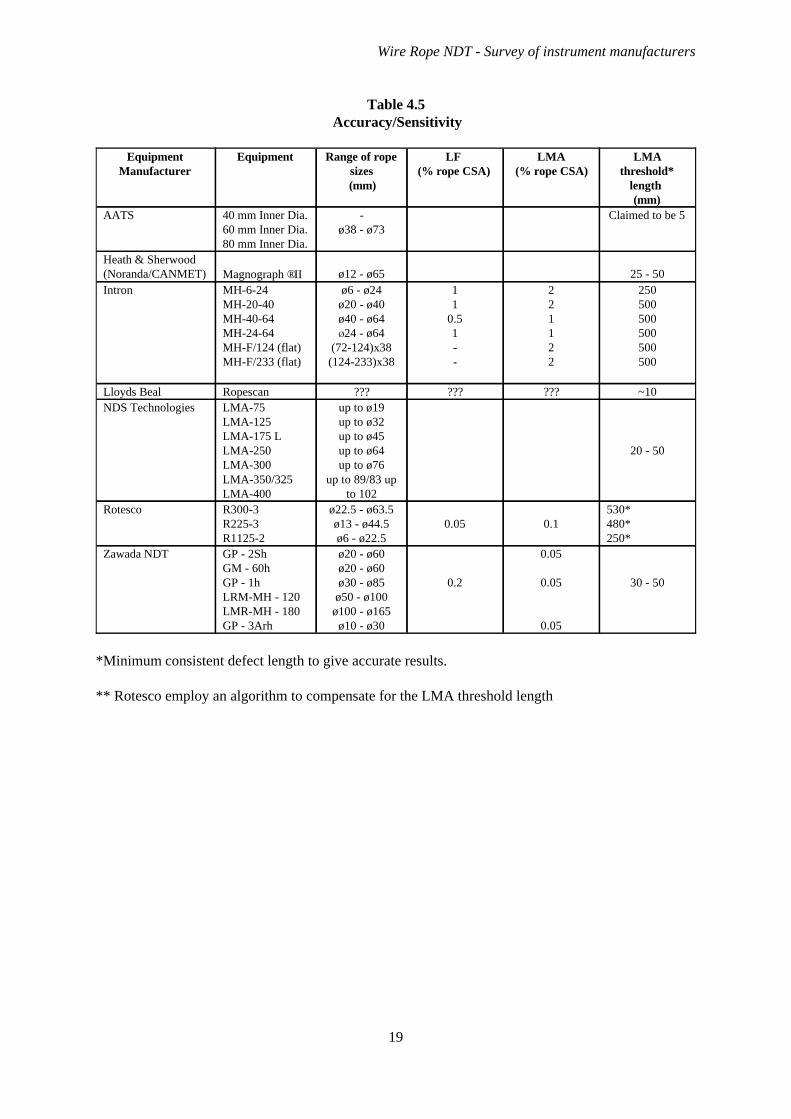
Table 4.5Accuracy/Sensitivity
30 - 50
0.05
0.05
0.05
0.2
ø20 - ø60ø20 - ø60ø30 - ø85
ø50 - ø100ø100 - ø165
ø10 - ø30
GP - 2ShGM - 60hGP - 1hLRM-MH - 120LMR-MH - 180GP - 3Arh
Zawada NDT
530*480*250*
0.10.05ø22.5 - ø63.5ø13 - ø44.5ø6 - ø22.5
R300-3R225-3R1125-2
Rotesco
20 - 50
up to ø19up to ø32up to ø45up to ø64up to ø76
up to 89/83 upto 102
LMA-75LMA-125LMA-175 LLMA-250LMA-300LMA-350/325LMA-400
NDS Technologies~10?????????RopescanLloyds Beal
250500500500500500
221122
11
0.51--
ø6 - ø24ø20 - ø40ø40 - ø64Ø24 - ø64
(72-124)x38(124-233)x38
MH-6-24MH-20-40MH-40-64MH-24-64MH-F/124 (flat)MH-F/233 (flat)
Intron25 - 50ø12 - ø65Magnograph ®II
Heath & Sherwood(Noranda/CANMET)
Claimed to be 5-ø38 - ø73
40 mm Inner Dia.60 mm Inner Dia.80 mm Inner Dia.
AATS
LMAthreshold*
length (mm)
LMA (% rope CSA)
LF (% rope CSA)
Range of ropesizes
(mm)
EquipmentEquipmentManufacturer
*Minimum consistent defect length to give accurate results.
** Rotesco employ an algorithm to compensate for the LMA threshold length
Wire Rope NDT - Survey of instrument manufacturers
19

Table 4.6Calibration and interpretation of the output signal
Calibration of the LF channels is performed by the manufacturer.Calibration of the LMA channel may be performed with a referencespecimen (supplied with the test head - a steel rod) and should be performedjust before the rope test when the rope is in the sensing head.
Real time chart recording on paper is a basic operation of the MD120.Additionally, (or instead of this) digital data acquisition may be used byemploying a PCMCIA memory card. Data thus obtained may be copied toa computer hard disc for processing. Browsing software is available, whichalso includes a data export facility, allowing data to be exported to softwaresuch as Microsoft Excel or Matlab.
Zawada NDT
The appropriate calibrated value for the LMA sensitivity control for aparticular rope diameter and construction is obtained from the “calibrationtable” in the Operating manual provided with the instrument (the instrumentis fully calibrated before it is shipped). The amplitude of the LF channelwould be set by the operator, so that in a good section of rope, the LF tracewould be 2 - 3 mm in width. A trial run using the rope to be tested willhelp determine appropriate settings. The computerised model (2D) includessoftware that calibrates the instrument.
Rotesco
Calibration should be performed in accordance with ASTEM E1571. Theprocess of calibration may be aided by use of NDT_CareTM software. Asignal enhancement algorithm is described by Weischedel (no date).NDT_CareTM software can make the trace independent of the rope speed.
NDT Technologies“Rod” calibration used on site.Lloyds Beal
Three calibration methods are suggested, all are based on ASTM E1571,and conducted on the rope to be examined. Software (WINTROS - basedon Windows 95/98NT) is available to download test data to a PC from thedata logger, process the test data, print LMA and LF traces and preparereports containing compressed LMA and LF data.
Intron
Calibration and data analysis features of the software is claimed to beextremely versatile. For detailed description refer to document by Geller &Kitzinger (1996).
Heath & Sherwood
(Noranda/CANMET)
A rod of known area is inserted as close to the rope surface as possible.The instrument is calibrated in “calibration mode” in the software package,which requires the user to enter values for deflection measured on the screenand the actual area gain.
AATS
EquipmentManufacturer
Wire Rope NDT - Survey of instrument manufacturers
20
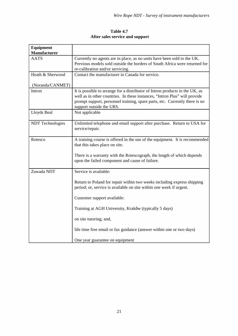
Table 4.7After sales service and support
Service is available:
Return to Poland for repair within two weeks including express shippingperiod; or, service is available on site within one week if urgent.
Customer support available:
Training at AGH University, Kraków (typically 5 days)
on site tutoring; and,
life time free email or fax guidance (answer within one or two days)
One year guarantee on equipment
Zawada NDT
A training course is offered in the use of the equipment. It is recommendedthat this takes place on site.
There is a warranty with the Rotescograph, the length of which dependsupon the failed component and cause of failure.
Rotesco
Unlimited telephone and email support after purchase. Return to USA forservice/repair.
NDT Technologies
Not applicableLloyds Beal
It is possible to arrange for a distributor of Intron products in the UK, aswell as in other countries. In these instances, “Intron Plus” will provideprompt support, personnel training, spare parts, etc. Currently there is nosupport outside the URS.
Intron
Contact the manufacturer in Canada for service.Heath & Sherwood
(Noranda/CANMET)
Currently no agents are in place, as no units have been sold to the UK.Previous models sold outside the borders of South Africa were returned forre-calibration and/or servicing.
AATS
EquipmentManufacturer
Wire Rope NDT - Survey of instrument manufacturers
21
5. DISCUSSION AND CONCLUSIONS
There is a limited range of wire rope NDT instruments which are likely to be used in the UK, but thereare no agreed performance specifications for such instruments, and all have their own particularfeatures, advantages and disadvantages. All these instruments have the capability to provide aneffective enhancement to the reliability of rope inspection, but these benefits are conditional upon theoperator’s competence, experience and ability, rather than the performance of the instrument.
It is essential that the operator of the NDT device understands the principles of operation of thatparticular device and is familiar with the limitations of the equipment. This should include sensitivityto wire breaks (taking account of gap and location in cross section); rope construction (especially withregards to multi-strand ropes and internal damage); and, the geometrical implication of LMAmeasurements and threshold length for accurate LMA.
It is also important that inspectors are able to use visual observation of the type and distribution ofdamage in combination with NDT measurements to infer rope integrity with respect to future use.LMA signals must not be treated per se as discard criteria, particularly because of the differencebetween “normal” (= snapshot) area measurements and the “effective” (i.e. cumulative) loss to loadbearing area.
Attention should also be paid to the comparison of NDT results with that obtained from the signaturewhen the rope was new, and subsequent tests. This comparison will give an indication of trendsregarding certain defects and could be useful in determining periods between NDT inspections,especially for ropes used in safety critical applications.
Calibration processes need to be understood especially in relation to whether “static” or “dynamic”.NDT operators need to be aware of other influences (such as rope tension or external magnetic fields)which can affect calibration.
The level of understanding required for effective and reliable rope inspection assisted by NDT goesbeyond the initial guidance given in instructions provided by the instrument manufacturers.
Wire Rope NDT - Survey of instrument manufacturers
22
6. ACKNOWLEDGEMENTS
The authors and HSE gratefully acknowledge the help of the following individuals and companies in thepreparation of this report.
tel: (416) 291 9821fax: (416) 291 4343email [email protected]://www.rotesco.com
Mr Rodney Pryde (President)Rotesco120 Melford Drive, unit 10ScarboroughOntarioCanadaM1B 2X5
tel: (860) 644-5655fax: (860) 644-5656email [email protected]://www.nditech.com
Dr Herbert R. Weischedel (President)NDT Technologies, Inc.P.O. Box 6371726 Ellington RoadSo. WindsorCT 06074, USA
tel: 01283 553416fax: 01283 552680
http://www.lloydsbeal.co.uk
Mr Colin CripwellLloyds Beal Ltd. (Ropescan)Bretby Business ParkAshby RoadStanhopeBretby, Burton-on-TrentDE15 0QD
tel: (7 095) 362-5638fax: (7 502) 222-4522email [email protected]
Dr Alexander Mironenko (Marketing Manager)Intron Plus Ltd.Krasnokazarmennaya Str. 17Moscow 111250Russia
tel: (705) 567-5313fax: (705) 567-8545contact Mr. J. P. Marinigh at:email [email protected]
Mr Frank KitzingerHeath & Sherwood (1964) Ltd.PO Box 34029 Duncan Avenue North.Kirkland Lake, OntarioCanadaP2N 3J2
tel: 00 27 11 638 4269fax: 00 27 11 638 4435email: [email protected]
Mr. Hein VenterAATSPO Box 61587Marshalltown2107Republic of South Africa
Wire Rope NDT - Survey of instrument manufacturers
23

tel: +48 32 271 6231fax: +48 32 275 2167email [email protected]://www.zawada.z.pl
Mr Kazimierz Zawada (Manager)Zawada NDT (Meraster)ul. Tatarkiewicza 8 m. 8PL-41-819 ZabrzePoland
Wire Rope NDT - Survey of instrument manufacturers
24

7. REFERENCES
ASTM E1571-93 Practice for electromagnetic examination of ferromagnetic steel wire rope ASTMstandard, November 1993.
Backeberg, R. (1993) Technical and economic implications of shafts research programme Proc. MineHoisting ‘93, London, 28-30 June 1993, Institute of Mining Electrical and Mining MechanicalEngineers, pp 11.1.1-11.1.10.
Bavins, T.G. (1998) NDT of semi-submersible production platform moorings Proc. Symposium onNon-destructive testing of steel wire ropes (December 1988) publishing by the British Institute ofNon-destructive testing 1989 109-117.
Chaplin, C.R. ed. (1999) OIPEEC Technical Meeting “The Non-destructive testing of rope” Kraków,September 1999 129-141 ISBN: 0 7049 1183 3
Chaplin, C.R. & Smith, I.H. (1993) Maintenance, inspection and discard of diving bell hoist ropes.Health and Safety Executive, Offshore Technology Report OTH 91 338, Published by HMSO, 1993,pp56.
Chaplin, C.R., Ridge, I.M.L. & Tytko, A.A. (1999) Measurement of abrasive wear on wire ropesusing non-destructive electro-magnetic inspection. ODN 0679 OIPEEC Bulletin 78 (1999) 67-80ISSN: 1018-8819.
Corden, C.H.H. (1988) A review of wire rope non-destructive testing and its practical application.Proc. Symposium on Non-destructive testing of steel wire ropes (December 1988) published by theBritish Institute of Non-destructive testing 1989. Also in Wire Industry, 56 669 (1989) and 57 670 (1989).
Dohm, M. (1999) An evaluation of magnetic rope testing instrument defect detection capabilities,particularly in respect of low rotation, multi-layer rope constructions. ODN 0681 OIPEECTechnical Meeting “The non-destructive testing of rope” Kraków, September 1999, 37-62 ISBN: 0-7094-1183-3.
Geller, L.B. & Kitzinger, F. (1996) User’s guide for the computer controlled Magnograph©IIVersion 1.0, Heath & Sherwood (1964) Ltd., Kirkland Lake, ON. Canada P2N 3J2, 1996
Golosinski, T.S. & Tytko, A.A. (1998) Magnetic examinations of wire ropes: loss of metallic area(LMA) measurement with Hall effect sensors ODN 0664 OIPEEC Bulletin No. 75 (1998) 27-36ISSN:1018-8819.
Hamelin, M., Kitzinger, F. & Geller, L.B. (1997) Computer prediction of wire rope endurance basedon NDT OIPEEC Round Table Conference Reading 1997, 103-110.
Hansel, J., Kwasnewski, J., Lankosz, L. & Tytko, A. (1992) Polish standard PN-92/G-46603. Linystalowe okragle, Oznaczanie stopnia zuzycia metoda magnetyczna. (Hoisting wire ropes, calculationsof loss of metallic area). Warsaw, 1992.
Heath & Sherwood, (no date) Magnograph®II computer based non-destructive wire rope testerPublished by Heath & Sherwood (1964) Ltd., Canada
Kündig, E. (1981) The magnetic-inductive testing of wire ropes Internationale Seilbahn Rundschau,3/1981.
Mironenko, A.S. & Sukhorukov, V.V. (1998). Non-destructive testing of steel wire ropes in RussiaINSIGHT 40 (1998)6 395-397.
Noble Denton (1996) Sub sea Electro magnetic Appraisal of wire mooring Lines (SEAL) phase 1report - Design Noble Denton Europe Ltd. Report number L17770/NDE/RWPS May 1996.
Wire Rope NDT - Survey of instrument manufacturers
25
Nussbaum, J-M (1999) Detection of broken wires using a high resolution magnetic test method ODN0688 OIPEEC Technical Meeting “The non-destructivetesting of rope” Kraków, September 1999129-141 ISBN: 0 7049 1183 3
SABS 0293:1996 Code of practice for condition assessment of steel wire ropes on mine windersSouth African Bureau of Standards 1994.
Tytko, A.A. & Golosinski, T.S. (1998) Magnetic rope examinations: definition of rope lay lengththrough LF signal analysis ODN 0669 OIPEEC Bulletin 76 (1998) 11-20 ISSN:1018-8819.
Venter, H. (1999) AATS continuous rope condition monitoring ODN 0687 OIPEEC TechnicalMeeting “The Non-destructive testing of rope” Kraków, September 1999 121-128 ISBN: 0 7049 11833
Weischedel, H.R. (no date) Electromagnetic wire rope inspection: signal generation, filtering andcomputer aided rope evaluation. Can be found at: http://www.ndttech.com/papers.htm.
Weischedel, H.R. & Chaplin, C.R. (1992) The inspection of offshore wire ropes: the state of the artProc. 24th Annual Offshore Technology Conference (OTC) Houston, Texas, May 4-7 1992, papernumber OTC 6969, 227-239.
Winter, S., Briem, U. & Nussbaum, J-M (1999) High resolution magnetic wire rope test - case studyODN 0689 OIPEEC Technical Meeting “The Non-destructive testing of rope” Kraków, September1999 143-151 ISBN: 0 7049 1183 3
Wire Rope NDT - Survey of instrument manufacturers
26
Top Related