


Languages
Pages
Legal


Auxiliary Views

Three views are usually all that are needed to illustrate simple objects◦Top◦Front◦Right
Sometimes only two views are necessary◦Cylinders
Views Refresher

A circle will look like an ellipse in the top, front, or right side view.
What’s a problem with these views when you’re working with circles?

One example is when there is a circle or an inclined plane or some other special type of feature of the object.
Sometimes, we just need to show an object at an odd angle because there is something very specialized about the object that cannot be seen from the front, top or right side views.
Sometimes, the principal views do not work…

A very special orthographic view that projects on any plane that is not one of the size primary views (front, back, top, bottom, left or right sides)
Perpendicular to the inclined part of the object
Circles really look like circles The true length, true width, true depth,
and true shape is shown
Auxiliary View

We needed to show the true length of a line or a part or the point of view of some part of an object or edge
We needed to show the true shape and size of part of an object
We have a circle and need to draw the circle first to get the front or side or top view (sometimes called reverse construction)
Why would we want to add another view?
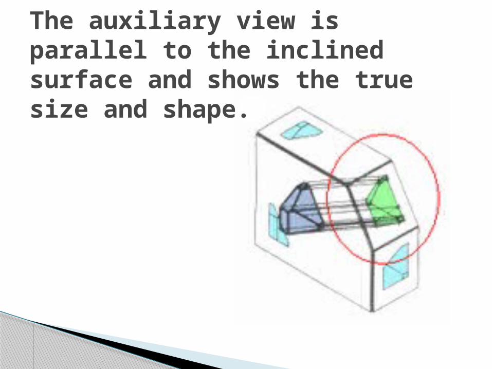
The auxiliary view is parallel to the inclined surface and shows the true size and shape.

Steps to Draw Primary Projections:

Steps to Draw Auxiliary View:

A reference plane is like the glass box projection
It is the edge of the related view For example, if the reference plane is
the front view, the auxiliary view will be projected out parallel from the inclined part as seen from the front view.
Consider this, the reference plan is the edge in the auxiliary view.
Reference Planes

An auxiliary view can be positioned anywhere around an object as the engineering designer chooses.
It is possible to then create additional auxiliary views from the auxiliary view.
View Classification

These are classified as:◦Primary – the first auxiliary view projected from one of the six principal views (top, front, sides, back, bottom)
◦Secondary – A single view projected from a primary auxiliary view
◦Tertiary – a single view projected from a secondary or another tertiary auxiliary view
View Classification

Primary Auxiliary Views are also defined by the dimension that is shown in the true size◦Depth – projected from the front view and
the depth dimension is the true length◦Height – projected from the top view and
the height dimension is the true length◦Width – projected from the side view and
the width dimension is the true length
Primary Auxiliary Views

Are there any questions about these different views before we go forward?
Primary Views & Primary, Secondary, & Tertiary Auxiliary ViewsDepth (front), Height (top) & Width (side) Auxiliary Views

Let’s make it easier on the engineering designer. If there is a hidden part or something that is not
inclined, we do not place it in an auxiliary view usually.
Also, we often only show the inclined part of the object which is called a partial auxiliary view.
This saves time and effort and is easier to view on a working drawing.
If the object is completely symmetrical, only half of the inclined part is drawn. This is called a half auxiliary.
Auxiliary Views

Drawing a Primary Auxiliary View
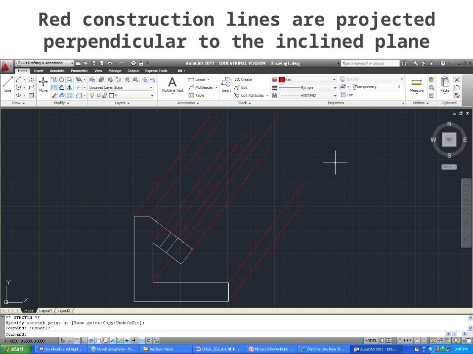
Red construction lines are projected perpendicular to the inclined plane

Red construction lines are projected for the right and side views

Circle where the projected angle construction line crosses the top and side views.
Draw a line connecting the two points. Then, draw a parallel line.

Draw arcs of the same radius and then draw lines parallel to front view
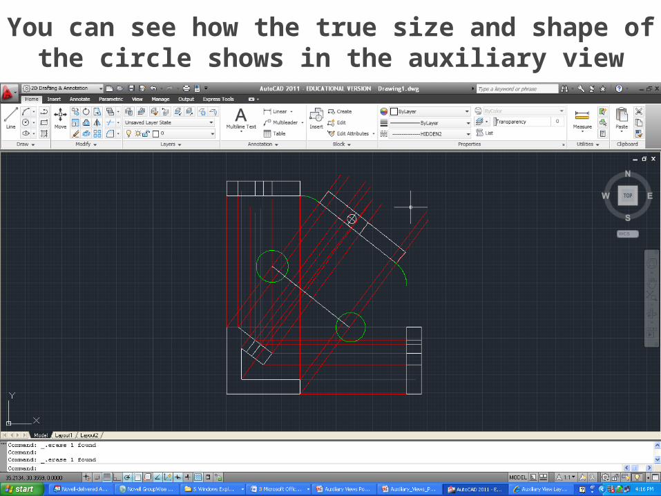
You can see how the true size and shape of the circle shows in the auxiliary view

Clean it up. No construction or projection lines.
Dimension correctly.

Now you can see why a partial auxiliary primary view is better…

An auxiliary view is simply another view that shows something like true size and true shape that the principal views like top, front, and right side can not show.
Reminder….
Top Related