


Languages
Pages
Legal


ArcGIS®
9Geoprocessing Commands Quick Reference Guide

Copyright © 2004-2008 ESRIAll rights reserved.Printed in the United States of America.
The information contained in this document is the exclusive property of ESRI. This work is protected under United States copyright law and other international copyright treaties and conventions. No part of this work may be reproduced or transmitted in any form or by any means, electronic or mechanical, including photocopying and recording, or by any information storage or retrieval system, except as expressly permitted in writing by ESRI. All requests should be sent to Attention: Contracts and Legal Services Manager, ESRI, 380 New York Street, Redlands, CA 92373-8100, USA. The information contained in this document is subject to change without notice.
Contributing WritersMelanie Harlow, Catherine Jones, Corey Tucker
U.S. Government reStriCted/Limited riGhtSAny software, documentation, and/or data delivered hereunder is subject to the terms of the License Agreement. In no event shall the U.S. Government acquire greater than RESTRICTED/LIMITED RIGHTS. At a minimum, use, duplication, or disclosure by the U.S. Government is subject to restrictions as set forth in FAR §52.227-14 Alternates I, II, and III (JUN 1987); FAR §52.227-19 (JUN 1987) and/or FAR §12.211/12.212 (Commercial Technical Data/Computer Software); and DFARS §252.227-7015 (NOV 1995) (Technical Data) and/or DFARS §227.7202 (Computer Software), as applicable. Contractor/Manufacturer is ESRI, 380 New York Street, Redlands, CA 92373-8100, USA.
ESRI, ArcView, ArcGIS, ArcInfo, ArcCatalog, ArcToolbox, ArcSDE, ModelBuilder, ARC/INFO, ArcMap, 3D Analyst, ArcEditor, and www.esri.com are trademarks, registered trademarks, or service marks of ESRI in the United States, the European Community, or certain other jurisdictions.
Other companies and products mentioned herein are trademarks or registered trademarks of their respective trademark owners.
Introduction 1
Analysis toolbox 5
Cartography toolbox 11
Conversion toolbox 17
Coverage toolbox 27
Data Management toolbox 45
Geocoding toolbox 85
Linear Referencing toolbox 87
Mobile toolbox 89
Multidimension toolbox 91
Server toolbox 93
Spatial Statistics toolbox 97
3D Analyst toolbox 109
Data Interoperability toolbox 129
Geostatistical Analyst toolbox 131
Network Analyst toolbox 133
Schematics toolbox 137
Spatial Analyst toolbox 139
Tracking Analyst toolbox 189
Index 191
Appendix A: Tool licensing A-1
Table of Contents

Introduction
1
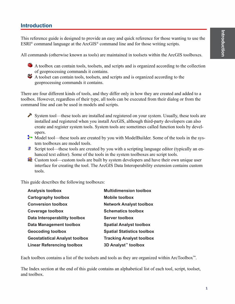
Introduction
This reference guide is designed to provide an easy and quick reference for those wanting to use the ESRI® command language at the ArcGIS® command line and for those writing scripts.
All commands (otherwise known as tools) are maintained in toolsets within the ArcGIS toolboxes.
A toolbox can contain tools, toolsets, and scripts and is organized according to the collection of geoprocessing commands it contains.
A toolset can contain tools, toolsets, and scripts and is organized according to the geoprocessing commands it contains.
There are four different kinds of tools, and they differ only in how they are created and added to a toolbox. However, regardless of their type, all tools can be executed from their dialog or from the command line and can be used in models and scripts.
System tool—these tools are installed and registered on your system. Usually, these tools are installed and registered when you install ArcGIS, although third-party developers can also create and register system tools. System tools are sometimes called function tools by devel-opers.
Model tool—these tools are created by you with ModelBuilder. Some of the tools in the sys-tem toolboxes are model tools.
Script tool—these tools are created by you with a scripting language editor (typically an en-hanced text editor). Some of the tools in the system toolboxes are script tools.
Custom tool—custom tools are built by system developers and have their own unique user interface for creating the tool. The ArcGIS Data Interoperability extension contains custom tools.
This guide describes the following toolboxes:
Analysis toolbox Multidimension toolbox Cartography toolbox Mobile toolbox Conversion toolbox Network Analyst toolbox Coverage toolbox Schematics toolbox Data Interoperability toolbox Server toolbox Data Management toolbox Spatial Analyst toolbox Geocoding toolbox Spatial Statistics toolbox Geostatistical Analyst toolbox Tracking Analyst toolbox Linear Referencing toolbox 3D Analyst™ toolbox
Each toolbox contains a list of the toolsets and tools as they are organized within ArcToolbox™.
The Index section at the end of this guide contains an alphabetical list of each tool, script, toolset, and toolbox.

Intr
oduc
tion
2 ArcGIS 9: Geoprocessing Commands Quick Reference Guide
All tools are available with the ArcInfo® license or the extension with which they are associated. However, many are available for use with ArcView® or ArcEditor™ (sometimes with limited func-tionality). Those available with ArcView and ArcEditor are denoted with a , and those available with ArcEditor are denoted with a .
Some tools, such as Clip, exist in multiple toolboxes. Therefore, an alias can be added as a suffix to the tool name when more than one toolbox is available. Examples of alias usages are clip_arc, where clip is the tool and arc is the suffix representing the Coverage toolbox, or clip_analysis, where the suffix represents the Analysis toolbox.
The alias list:
Analysis toolbox _analysis Multidimension toolbox _md Cartography toolbox _cartography Mobile _mobile Conversion toolbox _conversion Network Analyst toolbox _na Coverage toolbox _arc Schematics _schematics Data Interoperability toolbox _di Server toolbox _server Data Management toolbox _management Spatial Analyst toolbox _sa Geocoding toolbox _geocoding Spatial Statistics toolbox _stat Geostatistical Analyst toolbox _ga Tracking Analyst toolbox _ta Linear Referencing toolbox _l 3D Analyst toolbox _3d
The syntax of an example tool:
Union_arc <in_cover> <union_cover> <out_cover> {fuzzy_tolerance} {JOIN | NO_JOIN}
Where:
Union_arc is the tool and the components that follow are the parameters.
< > indicates required parameters.
{ } indicates optional parameters; these do not need to be included. One can be skipped using # if you need to apply only a portion of them.
The | indicates mutually exclusive arguments, and only one of the arguments in the list of options can be specified.
In some commands, there may be an ellipsis between two arguments, such as item1...item4. This indicates that you can give one or more (up to four in this example) names or values for that argument.
Example:Union_arc Treepolycov Newtreecov Finaltreecov # JOIN

ArcGIS Desktop
core geoprocessing tools


Analysis
toolbox
5
Analysis toolbox A suite of geoprocessing tools used to solve spatial or statistical problems.
Extract toolset Contains tools used to manipulate data into manageable datasets containing only the desired features and attributes.
Clip: Extracts those features from an input feature class that overlap with features from a clip feature class.
Clip <in_features> <clip_features> <out_feature_class> {cluster_tolerance}
• Theoutputfeatureclasswillhavetheattributesoftheinputfeatures.• Theinputfeaturesmaybeanygeometrytype,butclipfeaturesmusthavepolygongeometry.
Select: Extracts selected features from an input feature class or layer and stores them in the output feature class.
Select <in_features> <out_feature_class> {where_clause}
• IfnoSQLexpressionisincluded,thenallfeatureswillbeincludedintheoutputfeatureclass.• IfaSQLexpressionisusedbutreturnsnothing,theoutputfeatureclasswillbeempty.
Split: Clips the input features and stores them in multiple output datasets.Split <in_features> <split_features> <split_field> <out_workspace> {cluster_tolerance}
• Thesplitfielddatatypemustbecharacter.Theoutputfeatureclasseswillbenamedforsplitfieldvalues;therefore,theymuststartwithavalidcharacter.
• Thenumberofoutputfeatureclassesequalsthetotalnumberofuniquevaluesinthesplitfield.
Table Select: Extracts selected attributes from an input table or table view and stores them in an output table.
TableSelect <in_table> <out_table> {where_clause}
• TheinputcanbeanINFO®table,adBASE®table,ageodatabasetable,aVPFtable,afeatureclass,ora table view.
• IfaSQLexpressionisusedbutreturnsnothing,theoutputtablewillbeempty.

Ana
lysi
s to
olbo
x
6 ArcGIS 9: Geoprocessing Commands Quick Reference Guide
Overlay toolset Contains tools for topological integration of features based on symmetry.
Erase: Copies input features falling outside the erase polygon feature boundaries to the output.Erase <in_features> <erase_features> <out_feature_class> {cluster_tolerance}
• Inputfeaturepolygonsthatarecoincidentwitherasefeaturepolygonswillberemoved.• Theerasefeaturesmustbepolygons.
Identity: Intersects two feature classes. The output contains the input features as well as those overlapping features of the identity feature class.
Identity <in_features> <identity_features> <out_feature_class> {ALL | NO_FID | ONLY_FID} {cluster_tolerance} {NO_RELATIONSHIPS | KEEP_RELATIONSHIPS}
• Theinputfeaturesmustbepoint,multipoint,line,orpolygon.Theinputscannotbeannotationfeatures,dimensionfeatures,ornetworkfeatures.
• Theidentityfeaturesmustbepolygons.
Intersect: Creates an output feature class containing features that fall within the area common to both input datasets.
Intersect <features {Ranks};features {Ranks}...> <out_feature_class> {ALL | NO_FID | ONLY_FID} {cluster_tolerance} {INPUT | LINE | POINT}
• Theinputfeaturesmustbepoint,multipoint,line,orpolygon.Theinputscannotbeannotationfeatures,dimensionfeatures,ornetworkfeatures.
• Iftheinputshavedifferentgeometrytypes(thatis,lineonpoly,pointonline,andsoon),theoutputfeature class geometry type will default to the same as the input features with the lowest dimension geometry.
Spatial Join:Createsatypeoftablejoininwhichfieldsfromonelayer’sattributetableareappendedtoanotherlayer’sattributetablebasedontherelativelocationsofthefeaturesinthetwolayers.
SpatialJoin <target_features> <join_features> <out_feature_class> {JOIN_ONE_TO_ONE | JOIN_ONE_TO_MANY} {KEEP_ALL | KEEP_COMMON} {field_mapping} {INTERSECTS | IS_WITHIN | CONTAINS | CLOSEST} {search_radius} {distance_field_name}
Analysis
toolbox
7
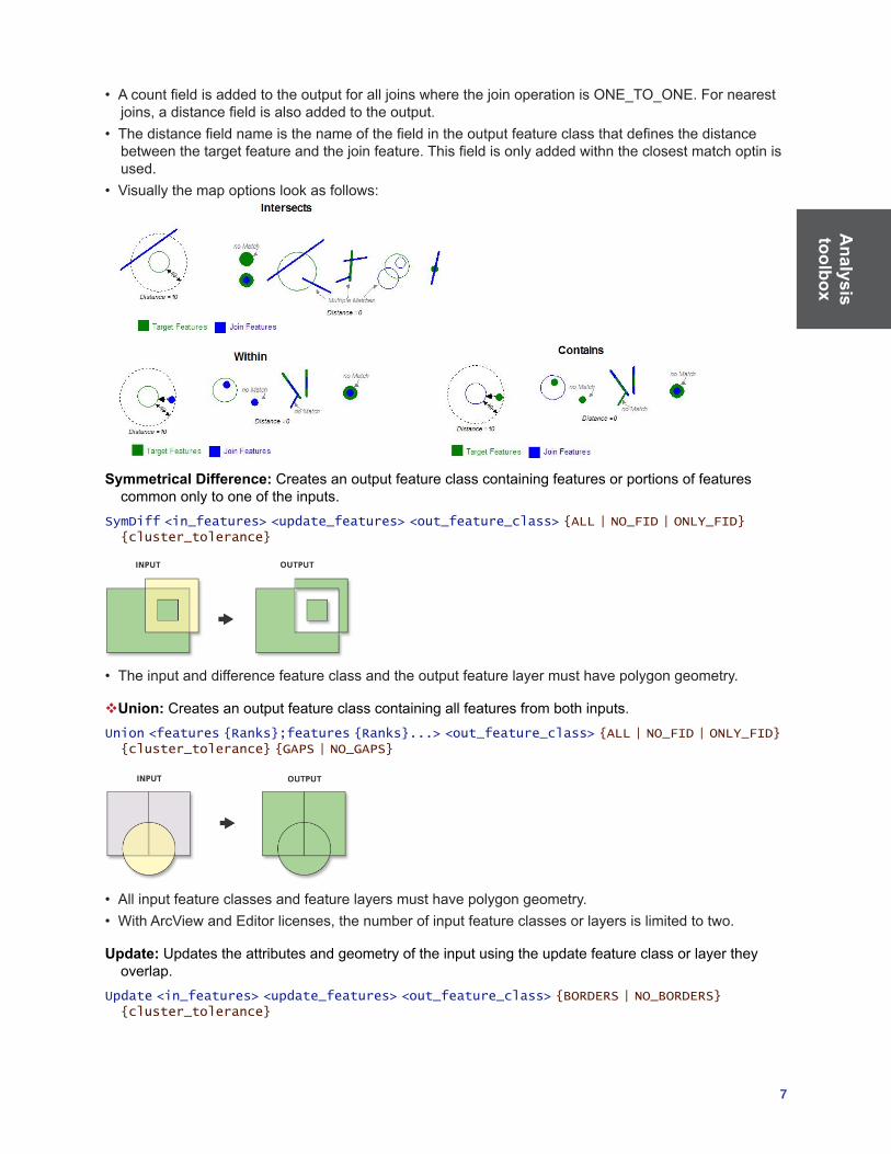
• AcountfieldisaddedtotheoutputforalljoinswherethejoinoperationisONE_TO_ONE.Fornearestjoins,adistancefieldisalsoaddedtotheoutput.
• Thedistancefieldnameisthenameofthefieldintheoutputfeatureclassthatdefinesthedistancebetweenthetargetfeatureandthejoinfeature.Thisfieldisonlyaddedwithntheclosestmatchoptinisused.
• Visuallythemapoptionslookasfollows:
Symmetrical Difference: Creates an output feature class containing features or portions of features
common only to one of the inputs.SymDiff <in_features> <update_features> <out_feature_class> {ALL | NO_FID | ONLY_FID} {cluster_tolerance}
• Theinputanddifferencefeatureclassandtheoutputfeaturelayermusthavepolygongeometry.
Union: Creates an output feature class containing all features from both inputs.Union <features {Ranks};features {Ranks}...> <out_feature_class> {ALL | NO_FID | ONLY_FID} {cluster_tolerance} {GAPS | NO_GAPS}
• Allinputfeatureclassesandfeaturelayersmusthavepolygongeometry.• WithArcViewandEditorlicenses,thenumberofinputfeatureclassesorlayersislimitedtotwo.
Update: Updates the attributes and geometry of the input using the update feature class or layer they overlap.
Update <in_features> <update_features> <out_feature_class> {BORDERS | NO_BORDERS} {cluster_tolerance}

Ana
lysi
s to
olbo
x
8 ArcGIS 9: Geoprocessing Commands Quick Reference Guide
• Theinputfeaturesandupdatefeaturesmustbeoftypepolygon,andtheirnamesmustmatch.
Proximity toolset Containstoolstodeterminespatialrelationshipsamongfeatures,withrespecttothedistancerelationships between features.
Buffer:Createsbufferpolygonstoaspecifieddistancearoundtheinputfeatures.Buffer <in_features> <out_feature_class> <buffer_distance_or_field> {FULL | LEFT | RIGHT | OUTSIDE_ONLY} {ROUND | FLAT} {NONE | ALL | LIST} {dissolve_field;dissolve_field...}
• Featureswillnotbebufferediftheirbufferdistanceiszero.• Whenbufferingpolygonfeatures,negativedistancescanbeusedtocreatebuffersontheinsideofthe
polygon features.
Create Thiessen Polygons: Converts input points to an output feature class of Thiessen proximal polygons.
CreateThiessenPolygons <in_features> <out_feature_class> <ONLY_FID | ALL>
• Thiessenpolygonshavetheuniquepropertythateachpolygoncontainsonlyoneinputpoint,andanylocation within a polygon is closer to its associated point than to the point of any other polygon.
• ThiessenpolygonscanbeusedtoapportionapointcoverageintopolygonsknownasThiessenorVoronoipolygons.
Generate Near Table: Determines the distance from each point in the input to the nearest feature in the nearfeatureclassorlayer,withinthesearchradius,andoutputstoatable.
GenerateNearTable <in_features> <near_features;near_features…> <out_table> {search_radius} {NO_LOCATION | LOCATION} {NO_ANGLE | ANGLE} {CLOSEST | ALL} {closest_count}
Analysis
toolbox
9
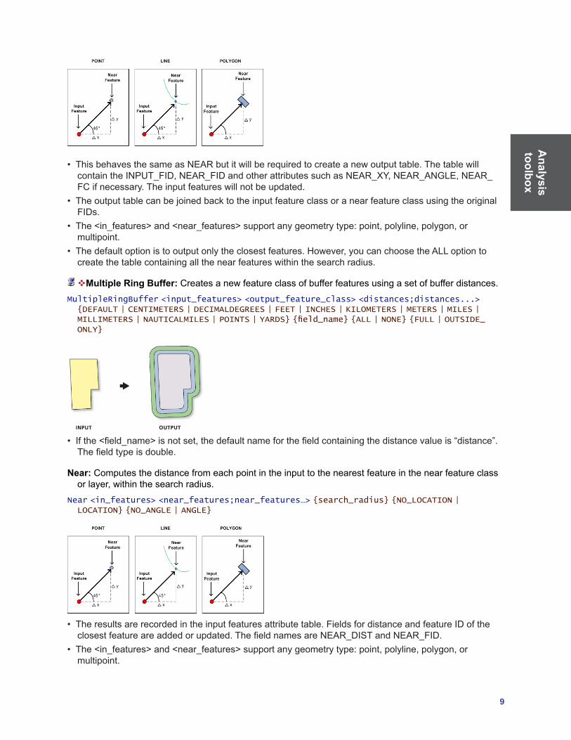
• ThisbehavesthesameasNEARbutitwillberequiredtocreateanewoutputtable.ThetablewillcontaintheINPUT_FID,NEAR_FIDandotherattributessuchasNEAR_XY,NEAR_ANGLE,NEAR_FCifnecessary.Theinputfeatureswillnotbeupdated.
• TheoutputtablecanbejoinedbacktotheinputfeatureclassoranearfeatureclassusingtheoriginalFIDs.
• The<in_features>and<near_features>supportanygeometrytype:point,polyline,polygon,ormultipoint.
• Thedefaultoptionistooutputonlytheclosestfeatures.However,youcanchoosetheALLoptiontocreate the table containing all the near features within the search radius.
Multiple Ring Buffer: Creates a new feature class of buffer features using a set of buffer distances. MultipleRingBuffer <input_features> <output_feature_class> <distances;distances...> {DEFAULT | CENTIMETERS | DECIMALDEGREES | FEET | INCHES | KILOMETERS | METERS | MILES | MILLIMETERS | NAUTICALMILES | POINTS | YARDS} {field_name} {ALL | NONE} {FULL | OUTSIDE_ONLY}
• Ifthe<field_name>isnotset,thedefaultnameforthefieldcontainingthedistancevalueis“distance”.Thefieldtypeisdouble.
Near: Computes the distance from each point in the input to the nearest feature in the near feature class orlayer,withinthesearchradius.
Near <in_features> <near_features;near_features…> {search_radius} {NO_LOCATION | LOCATION} {NO_ANGLE | ANGLE}
• Theresultsarerecordedintheinputfeaturesattributetable.FieldsfordistanceandfeatureIDoftheclosestfeatureareaddedorupdated.ThefieldnamesareNEAR_DISTandNEAR_FID.
• The<in_features>and<near_features>supportanygeometrytype:point,polyline,polygon,ormultipoint.

Ana
lysi
s to
olbo
x
10 ArcGIS 9: Geoprocessing Commands Quick Reference Guide
Point Distance: Computes the distance between each point in a feature class or layer to all points in a different feature class or layer.
PointDistance <in_features> <near_features> <out_table> {search_radius}
• Theresultsarerecordedinanoutputtablecontainingitemsforthefeature’sIDandDISTANCE.ThefieldnamesareINPUT_FID,NEAR_FID,andDISTANCE.
Statistics toolset Contains tools that perform standard statistical analysis on attribute data.
Frequency:Calculatesfrequencystatisticsforoneormorefieldsinatable.Frequency <in_table> <out_table> <frequency_fields;frequency_fields...> {summary_ields; summary_fields...}
• Theoutputtablewillcontainthefieldfrequencyandthespecifiedfrequencyfield(s)andsummaryfield(s).
Summary Statistics:Calculatessummarystatisticsforoneormorefieldsinatable.Statistics <in_table> <out_table> <statistics_field{Statistic Type};statistics_field{Statistic Type}...> {case_field;case_field...}
• Thefollowingstatisticaloperationsareavailablewiththistool:sum,mean,maximum,minimum,range,standarddeviation,first,andlast.Themedianoperationisnotavailable.
• TheAddFieldbutton,usedtodefinethestatisticsfields,isusedonlyinModelBuilder™.• Multiplecasefieldscanbedefinedwhencalculatingthestatistics.

Cartography toolbox
11
Cartography toolbox Containstoolsdesignedtoproducedataandsupportmapproductionforspecificmapsinawaythatmeetsaspecificcartographicstandard.
Graphic Quality toolset Contains a tool that allows you to construct polygons that identify the location where two features share the same graphic space.
Detect Graphic Conflict:Detectsgraphicconflictsbetweenfeaturerepresentationsandstorestheoverlaps as polygons in the output feature class.
DetectGraphicConflict <in_features> <conflict_features> <out_feature_class> {conflict_distance} {line_connection_allowance}
• Thistoolworksonfeaturerepresentationsonly,notfeaturegeometries.Theinputandconflictfeaturelayersmustcontainrepresentations;otherwise,thetoolwillnotexecute.
• Theconflictcalculationisbasedonareferencescale.IfyouaccessthistoolfromArcMap™,thereference scale of the data frame containing the input layers will be used unless an explicit reference scalehasbeensetintheArcToolboxenvironmentsettings.IfyouaccessthetoolfromArcCatalog™,areferencescalemustbespecifiedintheenvironmentsettings;otherwise,thetoolwillnotexecute.
• Theoutputfeatureclassstorespolygons,eachrepresentinganareaofgraphicconflictbetweenaninputrepresentationandaconflictrepresentation.
Masking toolset ContainstoolstoconstructmaskingpolygonstousewithvariabledepthmaskinginArcMap,whichobscures some feature symbology to help make clearer and more legible maps.
Cul-De-Sac Masks:Createsafeatureclassofpolygonmasksfromasymbolizedinputlinelayer.CuldeSacMasks <input_layer> <output_feature_class> <reference_scale> <spatial_reference> <margin> {ONLY_FID | NO_FID | ALL}
• Thistoolonlyacceptslinelayersasinput.• Thistoolonlycreatesmasksattheunconnectedendsoflinesintheinputlayer.Theseunconnected
ends in the input layer are referred to as cul-de-sacs. • Alineendisconsideredconnectedifitsharesitsendpointwiththeendpointofanotherline.• Iftheinputlinelayercontainsmultipartlinegeometries,thencul-de-sacmasksarecreatedforallunconnectedlineends,includingtheendsofpartswithinmultipartlines.
Feature Outline Masks:Createsmaskpolygonsataspecifieddistanceandshapearoundthesymbolizedfeaturesintheinputlayer.
FeatureOutlineMasks <input_layers> <output_feature_class> <reference_scale> <spatial_reference> <margin> <CONVEX_HULL | BOX | EXACT_SIMPLIFIED | EXACT> <ALL_FEATURES | ONLY_PLACED> {ONLY_FID | NO_FID | ALL}
• Thistoolacceptspoint,line,andpolygonfeaturelayersaswellasgeodatabaseannotationlayersasinput.
• Marginvaluesarespecifiedineitherpageunitsormapunits.Mostofthetimeyouwillwanttospecifyyour margin distance value in page units.
• Iftheinputlayerisanannotationlayer,thereferencescalewillbeautomaticallysettothereferencescaleofthelayer’sfeatureclasstoensureaccuratecalculationofthemask.

Car
togr
aphy
to
olbo
x
12 ArcGIS 9: Geoprocessing Commands Quick Reference Guide
Intersecting Layers Masks:Createsmaskingpolygonsataspecifiedshapeandsizeattheintersectionsofsymbolizedinputlayers.
IntersectingLayersMasks <masking_layer> <masked_layer> <output_feature_class> <reference_scale> <spatial_reference> <margin> <CONVEX_HULL | BOX | EXACT_SIMPLIFIED | EXACT> <ALL_FEATURES | ONLY_PLACED> {ONLY_FID | NO_FID | ALL}
• Thistoolacceptspoint,line,andpolygonfeaturelayersaswellasgeodatabaseannotationlayersasinput.
• Whencreatingmasks,itisimportanttoknowthataddingmaskstomapsaddscomplexitythatwillslowmapdrawingandaffectmapprintingandexporting.Generally,therearethreethingstoconsiderwhencreatingmasksforamap:(1)thenumberofmasks,(2)thecomplexityofthemasks,and(3)whetherthemaskswillbeusedtomaskpolygonfeaturesfilledwithmarkerorlinesymbols.
• Maskswillbecreatedifthemargindistanceiszeroornegative.Amarginsizeofzerowillcreateapolygonthatrepresentstheexactshapeofthesymbolizedfeature.Anegativemarginwillresultinapolygonsmallerthanthesymbolizedfeature.Generally,amarginvaluelargerthanzerowillbespecifiedtoproducethedesiredmaskingeffect.
Representation Management toolset Contains tools that manage feature class representations and representation overrides.
Add Representation: Adds a feature class representation to a feature class.AddRepresentation <in_features> <representation_name> {rule_id_field_name} {override_field_name} {STORE_CHANGE_AS_OVERRIDE | MODIFY_FEATURE_SHAPE} {import_rule_layer} {ASSIGN | NO_ASSIGN}
• Theinputmustbeageodatabasefeatureclass.• Specifyanimportrulelayertoimportrepresentationrulesfromanexistinglayerfilethatsymbolizesfeatureswithafeatureclassrepresentation.Alltherepresentationrulesoftheimportrulelayerfilewillbe copied into this feature class representation.
• Iftheimportrulelayerhasthesamesourcefeatureclassastheinputfeatureclass,youcancheckAssignRuleIDs(orusetheASSIGNoptioninascriptoratthecommandline)toassignrepresentationrules to features to match the RuleID assignments of the import rule layer.
Calculate Representation Rule: Applies existing representation rules to features in a feature class representationbycalculatingtheRuleIDfield.
CalculateRepresentationRule <in_features> <representation> <representation_rule>
Drop Representation: Deletes a feature class representation from a feature class.DropRepresentation <in_features> <representation>
• Onceafeatureclassrepresentationisdeletedfromafeatureclass,allrepresentationrulesandfeatureoverrides associated with that representation are deleted.
Remove Override: Removes geometry overrides and/or representation property overrides from a feature class representation.
RemoveOverride <in_features> <representation> {BOTH | GEOMETRY_OVERRIDE | REPRESENTATION_PROPERTY_OVERRIDE}
• Oncetheoverrideofafeatureisremoved,thestandardrepresentationrulewillapply.

Cartography toolbox
13
Select Feature By Override: Selects features within a feature class representation that have shape and/or representation property overrides.
SelectFeatureByOverride <in_representations> {BOTH | GEOMETRY_OVERRIDE | REPRESENTATION_
PROPERTY_OVERRIDE}
Update Override:Movesfeaturerepresentationoverridesfromthedefaultoverridefieldtoexplicitfieldsasdefinedbytherepresentationrulesinafeatureclassrepresentation.
<in_features> <representation> {REPRESENTATION_PROPERTY_OVERRIDE | GEOMETRY_OVERRIDE | BOTH}
• Thefieldstobeupdatedmustbeaddedandassociatedwiththecorrespondentoverrideattributespriorto using this tool.
Symbolization Refinement toolset Containstoolsthatallowyoutoenrichthesymbologyusedbyyourrepresentations,includingthealignmentandtypeofsymbols,aswellascreatecustomsymbologyforbridgesandtunnels.
Align Marker To Stroke Or Fill: Aligns the representation marker symbols of a point feature class to the neareststrokeorfillrepresentationsymbolsinalineorpolygonfeatureclasswithinaspecifiedsearchdistance.
AlignMarkerToStrokeOrFill <in_point_features> <in_line_or_polygon_features> <search_distance> {PERPENDICULAR | PARALLEL}
• Markersbeyondthesearchdistancearenotaffected.• Thechangeswillbestoredasoverrides.
Calculate Geodesic Angle:Calculatesgeodesicanglesfortheinputfeaturesaccordingtothedefinedcoordinatesystemandassignstheanglevaluestothespecifiedfieldinthefeatureclassthatcontainsthe input features.
CalculateGeodesicAngle <in_features> <angle_field>
• Theinputfeaturescanbepoints,lines,orpolygons.Forapointfeature,thepointlocationwillbeusedtocalculatethegeodesicangle.Foralineorpolygonfeature,thecenterpoint(centroid)ofgeometrywill be used.
• YoucanusetheAddFieldtooltoaddanumericalfieldtothefeatureclasscontainingtheinputfeaturesto store the calculated values.
• ThecoordinatesystemusedinthecalculationisdefinedinthegeoprocessingEnvironmentSettings>CartographySettings.Ifitisnotdefined,thetoolwillusetheonefromthemapifyouareinArcMap,orit will not execute if you are in ArcCatalog.
• Thestoredanglesareindecimaldegrees.
Calculate Line Caps:Calculatesthecaptype(endingstyle)fordouble-linesymbolsintheinputrepresentations.
CalculateLineCaps <in_representations> {BUTT | SQUARE} {CASED_LINE_DANGLE |TRUE_DANGLE}
• Thelinecaptypedefineshowtheendsoflinesegmentsaredrawnusingadouble-linesymbol.Bydefault,aroundlinecapwillbeused.YoucanusethistooltochangethecaptypetoBUTTorSQUARE.
• Thecalculatedcaptypeswillbestoredasrepresentationpropertyoverrides.Tochangebacktoroundcaps,youcanjustremovetherepresentationpropertyoverrides.
Car
togr
aphy
to
olbo
x
14 ArcGIS 9: Geoprocessing Commands Quick Reference Guide
• Thedangleoptionsareveryspecific.TheTRUE_DANGLEmeanstheendofalinearfeature,forexample,thedead-endofaroad.Whenthisoptionisused,thetoolwillcalculatelinecapsfortruedanglesonly.TheCASED_LINE_DANGLEiswherealinearfeaturestillcontinues,buttherepresentationchangesfromadouble-lineorcased-linesymboltoasingle-linesymbol.Whenthisoptionisused,thetoolwillcalculatelinecapsforbothtruedanglesandcased-linedangles.
Calculate Polygon Main Angle: Calculates the main angles of the input polygon features and assigns theanglevaluestothespecifiedfieldinthefeatureclassthatcontainsthepolygonfeatures.
CalculatePolygonMainAngle <in_features> <angle_field>
• YoucanusetheAddFieldtooltoaddanumericalfieldinthefeatureclasscontainingtheinputfeatuesto store the calculated values.
• Thelongestsideofapolygonisconsideredthemainaxisofthepolygon.Theangleofthemainaxiswillbe the main angle of the polygon.
• Thestoredanglesareindecimaldegrees.
Create Overpass:Generatesmaskpolygonsattheintersectionsofstrokerepresentationstosymbolizeone set of strokes passing above the other.
CreateOverpass <in_above_features> <in_below_features> <margin_along> <margin_across> <out_overpass_feature_class> <out_mask_relationship_class> {where_clause} {out_decoration_feature_class} {ANGLED | PARALLEL | NONE} {wing_tick_length}
• Requirestheindicationoffeaturesparticipatinginthecreationofanoverpass.• Featureclasseswithoutrepresentationsarenotsupportedbythistool.• Whenaboveandbelowrepresentationsarethesame,aSQLexpressionisencouragedforfurtherrefinementoffeatureselection.
• Overpassmasksarecreatedbasedontheuser-indicatedmarginsizes.• Existingoverpassfeatureclassesandexistingmaskrelationshipclasseswillnotbeoverwrittenifthesamenameisspecified.
Create Underpass:Generatesmaskpolygonsattheintersectionsofstrokerepresentationstosymbolizeone set of strokes passing under the other.
CreateUnderpass <in_above_features> <in_below_features> <margin_along> <margin_across> <out_underpass_feature_class> <out_mask_relationship_class> {where_clause} {out_decoration_feature_class} {ANGLED | PARALLEL | NONE} {wing_tick_length}
• Requirestheindicationoffeaturesparticipatinginthecreationofanunderpass.• Featureclasseswithoutrepresentationsarenotsupportedbythistool.• Whenaboveandbelowrepresentationsarethesame,aSQLexpressionisencouragedforfurtherrefinementoffeatureselection.
• Underpassmasksarecreatedbasedontheuser-indicatedmarginsizes.
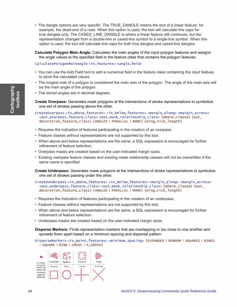
Disperse Markers:Findsrepresentationmarkersthatareoverlappingortooclosetooneanotherandspreads them apart based on a minimum spacing and dispersal pattern.
DisperseMarkers <in_point_features> <minimum_spacing> {EXPANDED | RANDOM | SQUARES | RINGS | SQUARE | RING | CROSS | X_CROSS}
Cartography toolbox
15
• Thistoolistypicallyusedwhenanalyzingandsymbolizinggeocodedeventdata,whereseveraleventsmayhappenatthesamelocationorcloselocations,andbecomesuperimposedoroverlappingwhensymbolized.
• Thetoolsearchesforcoincidentornearlycoincident(clustered)markersbasedonatolerancederivedfromthespecifiedMinimumSpacingandareferencescale;therefore,areferencescalemustbesetinorder for the tool to execute.
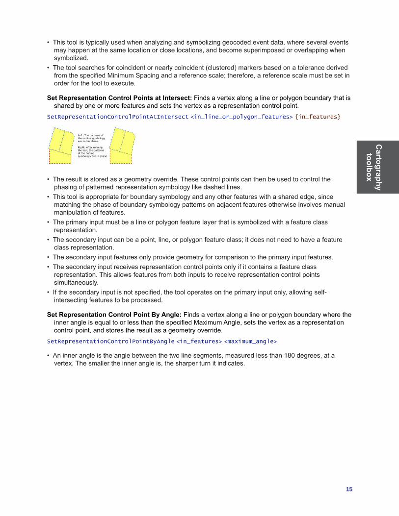
Set Representation Control Points at Intersect:Findsavertexalongalineorpolygonboundarythatisshared by one or more features and sets the vertex as a representation control point.
SetRepresentationControlPointAtIntersect <in_line_or_polygon_features> {in_features}
• Theresultisstoredasageometryoverride.Thesecontrolpointscanthenbeusedtocontrolthephasing of patterned representation symbology like dashed lines.
• Thistoolisappropriateforboundarysymbologyandanyotherfeatureswithasharededge,sincematching the phase of boundary symbology patterns on adjacent features otherwise involves manual manipulation of features.
• Theprimaryinputmustbealineorpolygonfeaturelayerthatissymbolizedwithafeatureclassrepresentation.
• Thesecondaryinputcanbeapoint,line,orpolygonfeatureclass;itdoesnotneedtohaveafeatureclass representation.
• Thesecondaryinputfeaturesonlyprovidegeometryforcomparisontotheprimaryinputfeatures.• Thesecondaryinputreceivesrepresentationcontrolpointsonlyifitcontainsafeatureclass
representation. This allows features from both inputs to receive representation control points simultaneously.
• Ifthesecondaryinputisnotspecified,thetooloperatesontheprimaryinputonly,allowingself-intersecting features to be processed.
Set Representation Control Point By Angle:FindsavertexalongalineorpolygonboundarywheretheinnerangleisequaltoorlessthanthespecifiedMaximumAngle,setsthevertexasarepresentationcontrolpoint,andstorestheresultasageometryoverride.
SetRepresentationControlPointByAngle <in_features> <maximum_angle>
• Aninnerangleistheanglebetweenthetwolinesegments,measuredlessthan180degrees,atavertex.Thesmallertheinnerangleis,thesharperturnitindicates.

Conversion toolbox
17
Conversion toolbox Contains tools that are used to convert data into various formats.
From Raster toolset Contains tools to output raster datasets to other formats.
Raster to ASCII:ConvertsarasterdatasettoanASCIIfilerepresentingrasterdata.RasterToASCII <in_raster> <out_ascii_file>
• BothintegerandfloatingpointrasterscanbeconvertedtoanASCIIformat.• TheNODATA_VALUEisthevalueintheASCIIfilethatwillbeassignedtotheNoDatacellsintheinput
raster. This value is normally reserved for those cells whose true value is unknown.• Theendofeachrowofdatafromtherasteristerminatedwithacarriagereturninthefile.
Raster to Float: Convertsarasterdatasetintoafileofbinaryfloating-pointvaluesrepresentingrasterdata.
RasterToFloat <in_raster> <out_float_file>
• Theoutputwillbeafloating-pointtextfile,asanIEEEfloating-pointformat,32-bitsignedbinaryfile.• Twooutputsarecreated,anIEEEfloating-pointformat,32-bitsignedbinaryfilewitha.fltextensionandanASCIIheaderfilewitha.hdrextension.Bothwillusethesameoutputfloating-pointrasterfilename.
• TheNODATA_VALUEisthevalueintheoutputfileassignedtothosecellsintheinputrasterthatcontainNoData.Thisvalueisnormallyreservedforthosecellswhosetruevalueisunknown.Bydefault,NoDatavaluesontheinputrasterwillhaveavalueof-9999intheoutputfloatfile.
Raster to Point: Converts a raster dataset to a point feature dataset.RasterToPoint <in_raster> <out_point_features> {raster_field}
• Foreachcelloftheinputrasterdataset,apointwillbecreatedintheoutputfeatureclass.Thepointswill be positioned at the centers of cells that they represent. The NoData cells will not be transformed into points.
• Theinputrastercanhaveanycellsizeandmaybeanyvalidrasterdataset.• Thefeatureoutputisassumedtobeashapefile.
Raster to Polygon: Converts a raster dataset to a polygon feature dataset.RasterToPolygon <in_raster> <out_polygon_features> {SIMPLIFY| NO_SIMPLIFY} {raster_field}
• Theinputrastercanhaveanycellsizeandmaybeanyvalidrasterdataset.• TheFieldparameterallowsyoutochoosewhichcolumnintherasterdatasetwillbecomeanattributeintheoutputpolygonfile.Thecolumncontainingthecellvalues(VALUE)willbecomeacolumnwiththeheadingGrid_codeintheattributetableoftheoutputfeatureclass.
Raster to Polyline: Converts a raster dataset to a polyline feature dataset.RasterToPolyline <in_raster> <out_polyline_features> {ZERO | NODATA} {minimum_dangle_length} {SIMPLIFY| NO_SIMPLIFY} {raster_field}
• Theinputrastercanhaveanycellsizeandmaybeanyvalidrasterdataset.• TheFieldparameterallowsyoutochoosewhichcolumnintherasterdatasetwillbecomeanattributeintheoutputpolylinefile.Thecolumncontainingthecellvalues(VALUE)willbecomeacolumnwiththeheadingGrid_codeintheattributetableoftheoutputfeatureclass.
• Thefeatureoutputisassumedtobeashapefile.

Con
vers
ion
tool
box
18 ArcGIS 9: Geoprocessing Commands Quick Reference Guide
From WFS toolset
WFS to Feature Class:Importsafeaturetypefromawebfeatureservice(WFS)toafeatureclassinageodatabase.
WFSToFeatureclass <input_WFS_server> <WFS_feature_type> <out_path> <out_name>
• UponsettingtheURLfortheWFSserver,allfeaturetypespublishedfromtheserverarelisted.ExamplescanincludeWFSfeaturestypesforschools,roadsandparcels.Oneoftheseisthenselectedandanoutputlocationandfeatureclassnamearespecified.Theoutputlocationcanbetheroot level of a geodatabase or a feature dataset within a geodatabase.
• BydefaultallfeaturesfromtheWFSsourceareaddedtothefeatureclass.Theextentenvironmentsettingcanbeusedtolimitthefeaturestojustthosethatintersectauserdefinedextent.Youcanalsospecifyanoutputconfigkeywordandoutputspatialgridsusingthegeodatabasesettingssectionoftheenvironment settings.
Metadata toolset Containsthetoolstovalidatethemetadatacontentaccordingtoaspecificmetadatastandardortoexportthemetadatacontenttostand-alonemetadatafilesthatcanbeusedwithothermetadatasoftware.
ESRI Metadata Translator:UsesESRI’smetadatatranslationenginetoexportmetadatacontentfromArcCatalogtoastand-alonefile.ThistoolrequirestheMicrosoft.NETFramework2.0.Thesetoolsareinstalled with the .NET Support install option.
ESRITranslator <source> <translator> {output} {logfile}
Metadata Importer:CopiesanXMLmetadatadocumentas-isfromthesourceitemtothetargetitem.ThistoolrequirestheMicrosoft.NETFramework2.0.Thesetoolsareinstalledwiththe.NETSupportinstall option.
MDImporter <source> <target>
Metadata Publisher:PublishesanXMLmetadatadocumenttoametadatacatalogsuchasanArcIMSMetadataService.ThistoolrequirestheMicrosoft.NETFramework2.0.Thesetoolsareinstalledwiththe .NET Support install option.
MDPublisher <source> <publisher> {url} {service} {user} {password}
• If you connect to ArcIMS in ArcCatalog with the same user name and password provided with this tool,theMetadataService’siconwillshowahandholdingapencilifyouhavepermissiontopublishdocuments to that service.
USGS MP Metadata Translator : Uses metadata parser to export or validate metadata content created usingtheFGDCmetadataeditor.ThistoolrequirestheMicrosoft.NETFramework2.0.Thesetoolsareinstalled with the .NET Support install option.
USGSMPTranslator <source> {config} {XML | NONE | HTML | TEXT | FAQ | SGML | DIF} {output} {errors}
• DocumentationforthemetadataparserutilitycanbefoundontheUSGSWebsite.• AnmetadataparserconfigurationfilecanbeusedtospecifyanextensionfilethatwillrecognizemetadataelementsthataredefinedinFGDCCSDGMprofiles.ExtensionandconfigurationfilesthatwillrecognizeESRI-definedmetadataelementsandESRI-ISOmetadataelementscanbefoundatESRI’smetadataWebpage.
• WhenmetadataiseditedusingArcCatalog,theXMLelementswillnotbeinthecorrectorderasspecifiedbytheFGDCCSDGMrules.Asaresult,metadataparserwillrecordwarningsintheerrorfile.
Conversion toolbox
19
XSLT Translator:UsesanXMLparsertotransformanXMLmetadatadocumentusinganXSLTstylesheetandexporttheresulttoastand-alonefile.ThistoolrequirestheMicrosoft.NETFramework2.0.These tools are installed with the .NET Support install option.
XSLTranslator <source> <xslt> <output>
To CAD toolset Contains tools to convert geodatabase features to native CAD formats.
Add CAD Fields:AddsfieldstotheinputtablebyselectingfromgroupsofCAD-specificfields,whichhavetheappropriatenameandtyperecognizedbytheExporttoCADtool.
AddCADFields <input_table> <ADD_ENTITY_PROPERTIES | NO_ENTITY_PROPERTIES> {ADD_LAYER_PROPERTIES | NO_LAYER_PROPERTIES} {ADD_TEXT_PROPERTIES | NO_TEXT_PROPERTIES} {ADD_DOCUMENT_PROPERTIES | NO_DOCUMENT_PROPERTIES} {ADD_XDATA_PROPERTIES | NO_XDATA_PROPERTIES}
• Iftheinputisatablevieworafeaturelayerwithajoinedtable,thefieldsareonlyaddedtothebasetable.
• AddingCADfieldstoafeatureclassintendedforexportandcalculatingvaluesintothosefieldsisaquickwaytospecifythevariousCADpropertiesforexport.
• ItisusefultoaddEntityPropertyfields,LayerPropertyfields,TextPropertyfields,andCADDocumentpropertyfieldstoseparatetablestokeepanormalizedsetoflookuptablesthatcanbejoinedtoexpressanorganizedCADstandardofhowCADfilesshouldbegeneratedfromfeatureclassdata.
Create CAD XData:CreatesatableformattedtoberecognizedbytheExporttoCADtoolasAutoCADextended entity data.
CreateCADXData <in_table> <fields;fields...> <RegApp> <ADE | TRADITIONAL>
• All input feature classes and/or feature layers are valid inputs to this tool. • XDataisonlyreadbyAutoCAD.• TheXDListfieldthatiscreatedbythisfunctionisreadbytheExporttoCADtoolwhenexportedto
AutoCAD.
Export to CAD: Creates one or more CAD drawings based on the values contained in one or more input feature classes or feature layers and supporting tables.
ExportCAD <in_features;in_features...> <DWG_R2000 | DGN_V8 | DWG_R14 | DXF_R14 | DXF_R2000 | DWG_R2004 | DXF_R2004 | DWG_R2005 | DXF_R2005> <Output_File> {IGNORE_FILENAMES_IN_TABLES | USE_FILENAMES_IN_TABLES} {OVERWRITE_EXISTING_FILES | APPEND_TO_EXISTING_FILES} {Seed_File}
• Allinputfeatureclassesand/orfeaturelayersandshapefilesarevalidinputstothistool.• ThistoolisgenerallyusedasthefinaltoolintheprocessofconvertingfeatureclassdatatoneworexistingCADdrawingfilesaccordingtoapredefinedsetofCADdrawingstandards.
• IftheCADdrawingfilesspecifiedbytheattributesoftheexportedfeaturesexist,CADobjectswillbeappendedtothosefiles.IftheCADfilesdonotexist,thespecifiedCADfileswillbecreatedwiththestandarddefaultsorusingtheoptionalSeedDrawingspecified.
• IftheCADentitypropertiesarenotspecified,thenentitieswillbegeneratedusingthedefaultentitypropertiesofthedrawingfileoranyexistinglayersymbologyincludedintheoptionalseeddrawing.
Set CAD Alias:RenamesoneormoreexistingfieldnamealiasesbymatchingcolumnsfromtheinputtablewithalistofCAD-specificfieldsofappropriatenames,whicharerecognizedbytheExporttoCAD tool.
SetCADAlias <input_table> <field_info>

Con
vers
ion
tool
box
20 ArcGIS 9: Geoprocessing Commands Quick Reference Guide
• IfafeatureclassintendedforexportalreadycontainsvaluesusefulfordrivingCADproperties,suchaslayername,butthefieldshavedifferentnames,assigningaCADfieldaliasonthattableusingtheAssignCADAliastoolisanefficientwaytohavetheExporttoCADtoolrecognizethosevaluesasCAD properties.
• Shapefilesarenotvalidinputtothisfunction,sincetheycannotmaintainaliasesforfields.Ifyouneedtouseashapefileasinput,converttheshapefiletoalayerfile.Layerfilesorfeatureclassesfromapersonal geodatabase or ArcSDE® geodatabase are valid inputs to this tool.
• Thistooloverwritestheinput,sobesuretomakeabackupoftheoriginaldata.
To Coverage toolset Contains a tool to convert any supported feature class format to a coverage.
Feature Class to Coverage: Creates a single coverage from one or more input feature classes or layers.FeatureClassToCoverage <features{Type};features{Type}...> <out_cover> {cluster_tolerance} {DOUBLE | SINGLE}
• TheclustertoleranceactsthesameasthefuzzytoleranceinArcInfoWorkstation.Thefuzzytoleranceoftheoutputcoveragewillbethesameastheclustertolerancespecifiedwhenexecutingthistool.Ifnoclustertoleranceisspecified,adefaultiscalculated.
• ItissuggestedyouruntheCreateLabelstoolaftersuccessfullyexecutingFeatureClassToCoverageto ensure all polygon features have an accurate label.
To dBASE toolset ContainsatooltoconverttablesintoadBASEformat.
Table to dBASE: ConvertsINFO,OLEDB,orgeodatabasetablestodBASEtables.TableToDBASE <input_tables;input_tables...> <output_folder>
• Thenameoftheoutputtableswillbebasedonthenameoftheinputtable.Toexplicitlycontroltheoutputnameandforsomeadditionalconversionoptions,usetheTableToTabletool.
• CopyRowsandTableToTablecanalsobeusedtoconvertatabletoadBASEfile.• Ifthenameoftheoutputtablealreadyexistsintheoutputfolder,anumberwillbeappendedtotheendtomakeitunique(forexample,OutputTab_1.dbf).
To Geodatabase toolset Contains tools to convert any supported vector or raster data type to a geodatabase.
Feature Class to Feature Class: Copiesafeatureclassintoageodatabaseortoashapefile.FeatureClassToFeatureclass <in_features> <out_path> <out_name> {where_clause} {field_mapping} {configuration_keyword}
• TheCopyFeaturestoolcanalsobeusedtoconvertashapefile,coveragefeatureclass,orgeodatabase(personalorSDE)featureclasstoashapefileorgeodatabase(personalorSDE)featureclass.
• SpatialindexesmaybespecifiedwhencreatinganSDEorpersonalgeodatabasefeatureclass.Thespatialindexisusedtoquicklylocatefeaturesthatmatchthecriteriaofaspatialsearch.Formostdata,onlyasinglespatialindexisrequired.
Feature Class to Geodatabase (multiple): Copies one or more feature classes or layers to a geodatabase feature class.
FeatureclassToGeodatabase <input_features;input_features...> <output_geodatabase>
Conversion toolbox
21
• Theinputscanincludeshapefiles,coveragefeatureclasses,VPFfeatureclasses,orgeodatabasefeature classes. The inputs can also be feature layers.
• Iftheinputisalayerwithselectedfeatures,onlythoseselectedfeatureswillbewrittentothenewoutput feature class.
• Thenameoftheoutputfeatureclasseswillbebasedonthenameoftheinputfeatureclass.Forexample,iftheinputisc:\myworkspace\gondor.shp,theoutputfeatureclasswillbenamedgondor.
• Ifthenamealreadyexistsintheoutputgeodatabase,anumberwillbeappendedtotheendtomakeitunique,forexample,“_1”.
Import CAD Annotation: Converts a collection of CAD annotation features into a geodatabase annotation feature class.
ImportCADAnnotation <input_features;input_features...> <output_feature_class> <reference_scale> {CLASSES_FROM_LEVELS | ONE_CLASS_ONLY} {NO_MATCH | MATCH_FIRST_INPUT} {NO_SYMBOL_REQUIRED | REQUIRE_SYMBOL} {STANDARD | FEATURE_LINKED} {linked_feature_class} {AUTO_CREATE | NO_AUTO_CREATE} {AUTO_UPDATE | NO_AUTO_UPDATE}
• Chooseareferencescalethatisroughlyequaltothescaleatwhichtheannotationwillnormallybedisplayed.Basedonthisreferencescale,symbolsandtextwillappearlargerasyouzoominontheannotationandsmallerasyouzoomoutfromyourannotation.
• Theconversionrequiresanexclusivelocksoitmaynotbeopenedbyanotherapplication.ItalsorequiresthatiftheannotationfeatureclassisinanArcSDEgeodatabase,itwillnotberegisteredasversioned.
Import Coverage Annotation: Imports coverage annotations into a geodatabase annotation feature class.
ImportCoverageAnnotations <input_features;input_features...> <output_feature_class> <reference_scale> {CLASSES_FROM_LEVELS | ONE_CLASS_ONLY} {NO_MATCH | MATCH_FIRST_INPUT} {NO_SYMBOL_REQUIRED | REQUIRE_SYMBOL} {STANDARD | FEATURE_LINKED} {linked_feature_class} {AUTO_CREATE | NO_AUTO_CREATE} {AUTO_UPDATE | NO_AUTO_UPDATE}
• Youcanconverteachcoverageannotationleveltoindividualannotationclassesormergethemintoasingle class.
• Theconversionrequiresanexclusivelocksoitmaynotbeopenedbyanotherapplication.ItalsorequiresthatiftheannotationfeatureclassisinanArcSDEgeodatabase,itwillnotberegisteredasversioned.
• Ifyouselectcoverageannotationfeaturesand/oruseadefinitionquery,onlythosefeaturesthatareselected and visible will be converted.
• Youcancreateaselectionsetofcoveragefeaturesandcreateanewlayerfromtheselection.Ifyouusethatnewlayerasinputtotheconversion,onlythosefeaturesinthelayerwillbeconverted.
Import from CAD:ImportsfromoneormoreCADfilestoageodatabase.ImportCAD <input_files;input_files...> <output_personal_geodatabase> {spatial_reference} {DO_NOT_EXPLODE_COMPLEX | EXPLODE_COMPLEX}
• Afixedsetoffeatureclasseswillbegeneratedinthespecifiedoutputfeaturedataset.Thesefeatureclassescontainthegeometryforthelines,areas,points,anddocumentextent,andoptionally,pointfeatureclassescanbegeneratedforeachuniqueblockorcellname.
• Thistoolcreatesanewgeodatabaseandwillnotappendtoanexistingone.• CADtextandattributeentitiesareconvertedtopointfeatures.
Raster to Geodatabase (multiple): Loads multiple raster datasets into a geodatabase or raster catalog.
RasterToGeodatabase <input_rasters;input_rasters...> <output_geodatabase> {configuration_keyword}
Con
vers
ion
tool
box
22 ArcGIS 9: Geoprocessing Commands Quick Reference Guide
• Theoutputisthelocationofthegeodatabasewhereyouwillstoretheraster.• Whenconvertingtherasterdatasettoapersonalgeodatabase,therasterdatasetisactuallystoredontheregularfilesysteminahiddenfolder.
• WhenconvertingtherasterdatasettoanArcSDEgeodatabase,therasterdatasetisstoredontheArcSDE server as a Raster SDE format.
Table to Geodatabase (multiple): ConvertsdBASE,INFO,orOLEDBtablestogeodatabasetablesand copies tables from one geodatabase to another.
TableToGeodatabase <input_table;input_table...> <output_geodatabase>
• TheinputscanincludedBASE,INFO,VPF,OLEDB,orgeodatabasetables.Theinputscanalsobetable views.
• Thenameoftheoutputtablewillbethesameastheinput.• Ifatable’snamealreadyexistsintheoutputgeodatabase,anumberwillbeappendedtotheendtomakeitunique(forexample,gondor_1).
Table to Table: ConvertsorcopiesdBASE,INFO,OLEDB,orgeodatabasetablestoadBASEorgeodatabase table.
TableToTable <in_rows> <out_path> <out_name> {where_clause} {field_mapping} {configuration_keyword}
• TheinputscanincludedBASE,INFO,VPF,OLEDB,orgeodatabasetables.Theinputscanalsobetable views.
• Todropfieldsduringtheconversion,settheirFieldInfoVisiblepropertytoFALSE.Thiswillnotaffectthe input table.
• Iftheinputisatableviewwithaselection,onlythoserowsthatareselectedwillbetransferredtotheoutput.
To KML toolset ContainstoolsusedtoconverttoKeyholeMarkupLanguage(KML)files.
Layer to KML:Convertsanin-memoryorfile-basedfeatureorrasterlayerintoaKeyholeMarkupLanguage(KML)filecontainingatranslationofESRIgeometriesandsymbologyintoKML.Thisfileiscompressedusingzipcompressionandwillhavea“.KMZ”extensionandcanbereadbyanyKMLclientincludingArcGISExplorer,ArcGlobe,andGoogleEarth.
LayerToKML <layer> <out_kmz_file> <layer_output_scale> {No_COMPOSITE| COMPOSITE} {boundary_box_extent} {image_size} {dpi_of_client}
• TheoutputKMZfilecannotalreadyexist.• YoucanreducethesizeoftheoutputKMZdocumentifyourlayerhasascale-dependentrendererandyouchooseanappropriate“LayerOutputScale”.
• Tooutputasinglerasterimagedrapedovertopographyusethe“Returnsinglecompositeimage”option.
• Tooutputeverylayerasseparaterasterimageusethe“ConvertVectortoRaster”option.
Map to KML:Convertsanin-memoryMaporMapDocumentintoaKeyholeMarkupLanguage(KML)filecontainingatranslationofESRIgeometriesandsymbologyintoKML.Thisfileiscompressedusingzipcompressionandwillhavea“.KMZ”extensionandcanbereadbyanyKMLclientincludingArcGISExplorer,ArcGlobe,andGoogleEarth.
MapToKML <in_map_document> <data_frame> <out_kmz_file> <map_output_scale> {NO_COMPOSITE| COMPOSITE} {VECTOR_TO_IMAGE | VECTOR_TO_VECTOR} {extent_to_export} {image_size} {dpi_of_client}
Conversion toolbox
23
• TheoutputKMZfilecannotalreadyexist.• YoucanreducethesizeoftheoutputKMZdocumentifyourmaphasscale-dependentrenderersandyouchooseanappropriate“MapOutputScale”.
• Tooutputasinglerasterimagedrapedovertopographyusethe“Returnsinglecompositeimage”option.
• Tooutputeverylayerasseparaterasterimageusethe“ConvertVectortoRaster”option.
To Raster toolset ContainstoolstoconvertanysupportedrasterformattoGRID,ERDASIMAGINE®,TIFF,orgeodatabaseformat.
ASCII to Raster:ConvertsanASCIIfilerepresentingrasterdataintoarasterdataset.ASCIIToRaster <in_ascii_file> <out_raster> {INTEGER | FLOAT}
• TheASCIIfilemustconsistofheaderinformationcontainingasetofkeywords,followedbycellvaluesinrow-majororder.Thefileformatis:
<NCOLS xxx>
<NROWS xxx>
<XLLCENTER xxx | XLLCORNER xxx>
<YLLCENTER xxx | YLLCORNER xxx>
<CELLSIZE xxx>
{NODATA_VALUE xxx}
row 1
row 2
.
.
.
row n
wherexxxisanumber,andthekeywordNODATA_VALUEisoptionalanddefaultsto-9999.Row1ofthedataisatthetopofthegrid,row2isjustunderrow1,andsoon.
• TheNODATA_VALUEisthevalueintheASCIIfiletobeassignedtothosecellswhosetruevalueisunknown.Intheraster,theywillbeassignedtoNoData.
• Cellvaluesshouldbedelimitedbyspaces.Nocarriagereturnsarenecessaryattheendofeachrowinthe grid. The number of columns in the header is used to determine when a new row begins.
• Thenumberofcellvaluesmustbeequaltothenumberofrowstimesthenumberofcolumns,oranerror will be returned.
DEM to Raster:ConvertsaUSGSDEMfileintoarasterdataset.DEMToRaster <in_dem_file> <out_raster> {FLOAT | INTEGER} {z_factor}
• Theresultingrasterwillhavesquarecells.IftheDEMhasadifferentsamplepointspacinginthexandydirections,itisresampledduringtheconversionprocess.ItisresampledusingbilinearinterpolationatacellsizeequaltothesmallerofthepointspacingsoftheDEMinthexory.
• Foroutputtoagridraster,DEMtoRastertransferstheprojectionandunitsinformationcontainedintheDEMheaderrecordtoamapprojectionfileintheoutputgriddirectory.Iftheoutputrasterisnotagrid,theprojectioninformationwillbetransferredtothe.auxfile.
Feature to Raster: Converts a feature dataset to a raster dataset.FeatureToRaster <in_features> <field> <out_raster> {cell_size}
• Anyshapefile,coverage,orgeodatabasefeatureclasscontainingpoint,line,orpolygonfeaturescanbe converted to a raster dataset.
Con
vers
ion
tool
box
24 ArcGIS 9: Geoprocessing Commands Quick Reference Guide
• Iftheinputfieldcontainsfloating-pointvalues,theoutputrasterwillbefloatingpoint;otherwise,itwillbeinteger.
• Theoutputcellsizewilldeterminethesizeofeachpixelintheoutputrasterdataset.
Float to Raster:Convertsafileofbinaryfloating-pointvaluesrepresentingrasterdataintoarasterdataset.
FloatToRaster <in_float_file> <out_raster>
• TheinputfileisanIEEEfloating-pointformat,32-bitsignedbinaryfile.• Twoinputsarerequired:thebinaryfloating-pointfilewitha.fltextension(<in_float_file>.flt)andanASCIIheaderfilewitha.hdrextension(<in_float_file>.hdr).Youonlyspecifythe.fltfile;however,thereneedstobeanexisting.hdrfileinthesamedirectorywiththesamefilename.
• TheASCIIfileconsistsofheaderinformationcontainingasetofkeywords.Thefileformatis:NCOLS xxx
NROWS xxx
XLLCENTER xxx | XLLCORNER xxx
YLLCENTER xxx | YLLCORNER xxx
CELLSIZE xxx
NODATA_VALUE xxx
BYTEORDER <MSBFIRST | LSBFIRST>
wherexxxisanumber,andthekeywordNODATA_VALUEisoptional.
Point to Raster: Converts point features to a raster dataset.PointToRaster <in_features> <value_field> <out_raster_dataset> {MOST_FREQUENT | SUM | MEAN | STANDARD_DEVIATION | MAXIMUM | MINIMUM | RANGE} {priority_field} {cellsize}
• Anyshapefile,coverage,orgeodatabasefeatureclasscontainingpointormultipointfeaturescanbeconverted to a raster dataset.
• Multipointsaretreatedasindividualpoints.• Theoutputcellsizeisthesizeofeachpixelintheoutputrasterdataset.• PriorityfieldisonlyusedwiththeMOST_FREQUENToption.
Polygon to Raster: Converts polygon features to a raster dataset.PolygonToRaster <in_features> <value_field> <out_raster_dataset> {CELL_CENTER | MAXIMUM_AREA | MAXIMUM_COMBINED_AREA} {priority_field} {cellsize}
• Anyshapefile,coverage,orgeodatabasefeatureclasscontainingpolygonfeaturescanbeconvertedtoa raster dataset.
• Iftheinputfieldcontainsfloating-pointvalues,theoutputrasterwillbefloatingpoint;iftheinputfieldcontainsintegervalues,theoutputrasterwillbeinteger;andiftheinputfieldcontainsstringvalues,theoutputrasterwillcontainanintegervaluefieldandastringfield.
• Theoutputcellsizeisthesizeofeachpixelintheoutputrasterdataset.
Polyline to Raster: Converts polyline features to a raster dataset.PolylineToRaster <in_features> <value_field> <out_raster_dataset> {MAXIMUM_LENGTH | MAXIMUM_COMBINED_LENGTH} {priority_field} {cellsize}
• Anyshapefile,coverage,orgeodatabasefeatureclasscontainingpolylinefeaturescanbeconvertedtoa raster dataset.
• Iftheinputfieldcontainsfloating-pointvalues,theoutputrasterwillbefloatingpoint;iftheinputfieldcontainsintegervalues,theoutputrasterwillbeinteger;andiftheinputfieldcontainsstringvalues,theoutputrasterwillcontainanintegervaluefieldandastringfield.
• Theoutputcellsizeisthesizeofeachpixelintheoutputrasterdataset.
Conversion toolbox
25
Raster to Other Format (multiple): Converts one or more raster dataset formats supported by ArcGIStoaBMP,GIF,GRID,IMAGINE,JPEG,JPEG2000,PNG,TIFF,orgeodatabaserasterdatasetformat.
RasterToOtherFormat <input_rasters;input_rasters...> <output_workspace> {GRID | BMP | GIF | IMAGINE Image | JP2000 | JPEG | PNG | TIFF}
• TheinputrasterdatasetscanbeanyvalidrasterdatasetthatArcGIScanrecognize.• Allowsyoutobatchconvertrasterdatasetsintoanotherrasterdatasetformat.Thisisusefulifyoureceiverasterdatasetsinoneformat,butyou(oryourclient)prefertouseBMP,GIF,GRID,IMAGINE,JPEG,JPEG2000,PNG,orTIFF.
To Shapefile toolset Containsatooltocreateshapefilesfromfeatureclasses.
Feature Class to Shapefile (multiple):Exportsoneormorefeatureclassestoshapefilesinadesignated folder.
FeatureclassToShapefile <input_features;input_features...> <output_folder>
• Thenameoftheoutputshapefilewillbethenameoftheinputfeatureclass.Forexample,iftheinputisc:\gdb.mdb\gondor,theoutputshapefilewillbenamedgondor.shp.Toexplicitlycontroltheoutputshapefilenameandforsomeadditionalconversionoptions,seetheFeatureClasstoFeatureClasstool.
• Iftheoutputshapefilealreadyexistsintheoutputfolder,anumberwillbeappendedtotheendtomakeitunique(forexample,gondor_1.shp).
• Thecoordinatesystemofeachoutputshapefilewillbethesameastheinputfeatureclasses.IftheOutputCoordinateSystemEnvironmentisset,theoutputwillbeprojectedtothatcoordinatesystem.


Coverage toolbox
27
Coverage toolbox ContainstheoriginalArcInfoWorkstationcommandsusedtoperformgeoprocessingtaskswithcoverages.
Analysis toolset Contains tools and toolsets used for geospatial processing.
Extract toolset Contains tools used to select features or parts of features to create a new coverage.
Clip:Extracts,usingacookie-cuttermethod,thosefeaturesorportionsoffeaturesfromaninputcoverage that overlap with a clip coverage polygon.
Clip <in_cover> <clip_cover> <out_cover> {POLY | LINE | POINT | NET | LINK | RAW} {fuzzy_tolerance}
• Clipmaintainslineardatabelongingtodifferentplanargraphsinthesamecoverage.Thesemayinclude arcs representing utility cables at different levels or a road passing over a stream. If there arearcsthatappeartointersectbutdonot,nodeswillnotbeinsertedattheapparentintersection.Coincident and colinear line segments are preserved; additional vertices may be inserted. Two colinear arcs—onerepresentingaroadthatfollowsthesecond,astream—aremaintained.
• Theclipcoveragemusthavepolygontopology.• BoundariesofinteriorpolygonsintheclipcoveragearenotusedinClip.Anyclipcoveragepolygon
whose internal number is greater than one is considered inside the Clipping window.
Select: Extracts features from the input coverage and stores them in an output coverage based on logical expressionsorbyapplyingthecriteriacontainedinaselectionfile.
Reselect <in_cover> <out_cover> <info_express;info_express...> {POLY | LINE | POINT | ANNO.subclass | ROUTE.subclass | SECTION.subclass | REGION.subclass} {selection_file} {out_feature_type}
• WhenusingthesameinputcoverageandoutputcoverageforfeatureclassesAnno,Section,Route,orRegion,theoutputfeatureclasssubclassnamemustbedifferentfromtheinputfeatureclasssubclassname.
• UseofindexeditemsintheQueryBuildercanspeedupthelogicalselectionprocess.YoucanusetheIndex Item tool to create an attribute index.
Split: Clips portions of the input coverage into multiple coverages.Split <in_cover> <split_cover> <split_item> <path> {POLY | LINE | POINT | NET | LINK | RAW} {fuzzy_tolerance}

Cov
erag
e to
olbo
x
28 ArcGIS 9: Geoprocessing Commands Quick Reference Guide
• TheoutputcoverageswillbenamedforSplitItemvalues;therefore,theymuststartwithavalidcharacter.
• Thesplitcoveragemusthavepolygontopology.• Thefeatureattributetableforeachoutputcoveragecontainsthesameitemsastheinputcoverage
feature attribute table.
Overlay toolset Contains tools used to calculate the various options when overlaying two coverages.
Erase: Erases the input coverage features or portions of features that overlap with the erase coverage polygons.
Erase <in_cover> <erase_cover> <out_cover> {POLY | LINE | POINT | NET | LINK | RAW} {fuzzy_tolerance}
• Inputcoveragepolygonsthatarecoincidentwitherasecoveragepolygonswillberemoved.• User-IDsforallfeatureswillbethesameintheoutputcoverageastheyareintheinputcoverage.• BoundariesofinteriorpolygonsintheerasecoveragearenotusedinErase.Anyerasecoverage
polygon whose internal number is greater than one is considered inside the erasing window; an internal polygonnumberofoneisconsideredoutside.Onlythoseinputfeatures(orportionsofthem)thatareoutside the erasing region are stored in the output coverage.
Identity:Computesthegeometricintersectionoftwocoverages,whereallfeaturesoftheinputcoverageand only those overlapping from the identity coverage are preserved.
Identity <in_cover> <identity_cover> <out_cover> {POLY | LINE | POINT} {fuzzy_tolerance} {JOIN | NO_JOIN}
• Theidentitycoveragemusthavepolygontopology.• LabelpointsaregeneratedineachoutputcoveragepolygonwhenthePOLYoptionisused.ThenewpolygonUser-IDsaresetequaltothepolygoninternalnumberminusone.WhentheLINEoptionisused,User-IDsoftheinputcoveragearemaintained.
Intersect: Computesthegeometricintersectionoftwocoverages,whereonlythosefeaturesintheareacommon to both coverages will be preserved.
Intersect <in_cover> <intersect_cover> <out_cover> {POLY | LINE | POINT} {fuzzy_tolerance} {JOIN | NO_JOIN}

Coverage toolbox
29
• Theintersectcoveragemusthavepolygontopology.• LabelpointsaregeneratedineachoutputcoveragepolygonwhenthePOLYoptionisused.ThenewpolygonUser-IDsaresetequaltothepolygoninternalnumberminusone.
Union: Computes the geometric intersection of two polygon coverages. All polygons from both coverages will be split at their intersections and preserved in the output coverage.
Union <in_cover> <union_cover> <out_cover> {fuzzy_tolerance} {JOIN | NO_JOIN}
• Theinputcoverageandtheunioncoveragemusthavepolygontopology.• Labelpointsaregeneratedineachoutputcoveragepolygon.ThenewpolygonUser-IDsaresetequal
to the polygon internal number minus one. • ExistinginputcoverageannotationiscopiedtotheoutputcoveragebyUnion.
Update: Replaces the input coverage areas with the update coverage polygons using a cut-and-paste type of operation.
Update <in_cover> <update_cover> <out_cover> {POLY | NET} {fuzzy_tolerance} {KEEP_BORDER | DROP_BORDER}
• Theinputcoverageandtheupdatecoveragemusthavepolygontopology.• Newlabelpointpositionsareonlygeneratedfortheoutputcoveragepolygonswhennecessary.TheUser-IDforeachpolygonisequaltoitsoldinputcoverageUser-ID(theupdatecoverageUser-IDforupdatedpolygons).Thus,youshouldattempttomaketheUser-IDvaluesintheinputcoveragedifferent from User-ID values in the update coverage to avoid having duplicate User-IDs in the output coverage.
• IfDROP_BORDERisused,polygonboundariesalongtheouteredgeoftheupdatecoveragearedropped.Eventhoughtheouterboundariesofsomeupdatepolygonsaredropped,theitemvaluesfor the update polygons that overlap input coverage polygons will be assigned to the polygons in the outputcoverage.TheDROP_BORDERoptionisnotrecommendedforregioncoveragesbecauseofthe possibility that some output regions may not be maintained.
Proximity toolset Contains tools used in geoprocessing analysis involving distance.
Buffer: Createsbufferpolygonsaroundspecifiedinputcoveragefeatures.Buffer <in_cover> <out_cover> {LINE | POLY | POINT | NODE} {buffer_item} {buffer_table} {buffer_distance} {fuzzy_tolerance} {ROUND | FLAT} {FULL | LEFT | RIGHT}

Cov
erag
e to
olbo
x
30 ArcGIS 9: Geoprocessing Commands Quick Reference Guide
• NegativeandpositivedistancescanbeusedforbufferdistancewiththePOLYoption.Itispossibletoshrink some polygons and grow others in the same coverage when the buffer item contains positive and negative numbers.
• TheROUND,FLAT,FULL,LEFT,andRIGHToptionsapplyonlytolinedata.• TheBufferfunctionworksinEuclideanspaceandusesatwo-dimensionalalgorithm.Abufferwillbethesamewidthnomatterwhatthecoordinatesystemis.Itwillnotreflectthecurvatureortheshapeoftheearth.Forthebestresults,generatethebufferinamapprojectionthatminimizesdistortionintheareaof interest.
Near:Computesthedistancefromeachpointinacoveragetothenearestarc,point,ornodeinanothercoverage.
Near <in_cover> <near_cover> <out_cover> {LINE | POINT | NODE} {search_radius} {NO_LOCATION | LOCATION}
• Distancevaluesarerecalculatedifthisitemalreadyexistsintheinputcoverage.Ifthedistanceitemisadded,itwillbeinthesameprecisionasthecoverage.
• Thecalculateddistancefrompointtoarcwillbefromthepointtothenearestlocationalongthearc.Thecalculated distance from point to node will be between the nearest node locations on the arcs.
Point Distance: Computes the distances between point features in one coverage to all points in a second coveragethatarewithinthespecifiedsearchradius.
PointDistance <from_cover> <to_cover> <out_info_table> {search_radius}
• Distanceissettozerowhennomatchisfoundwithinthesearchradiusforaparticularpoint.Ifnomatchingpointsarefound,thetoolgivesawarningandnooutputINFOtableiscreated.
• TheoutputINFOtablecanbecomeverylargewhenbothcoveragescontainmanypoints.Useasmallersearch radius to limit the number of combinations.
• Theresultsarerecordedinanoutputtablecontainingitemsfortheinternalnumbersanddistance.TheinputwiththehighestprecisionfordistanceistheoneusedfortheoutputINFOdistancefield.
Point Node: Transfers attributes from a point feature class to a node feature class.PointNode <point_cover> <node_cover> {search_radius}
Coverage toolbox
31
• Thecoverage-IDnumberforeachmatchingpointisstoredasthenode-IDnumberintheNAT.Iftherearenomatchestoanode,thenthenode-IDisequaltotheinternalnodenumber.
• Thepointcovermusthaveapointattributetable(PAT)forthiscommandtowork.• Thenodecovercanbethesameasthepointcover,inwhichcasetheattributesofthePATare
transferred to the NAT within the point coverage.
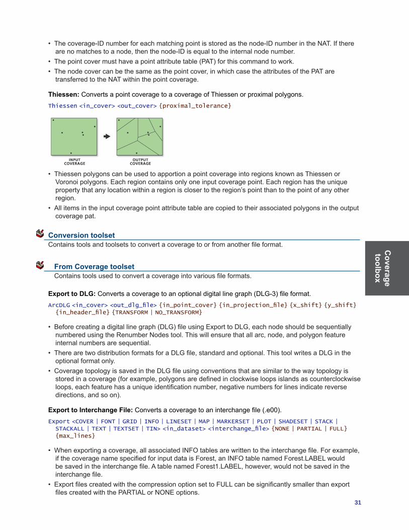
Thiessen: Converts a point coverage to a coverage of Thiessen or proximal polygons.Thiessen <in_cover> <out_cover> {proximal_tolerance}
• ThiessenpolygonscanbeusedtoapportionapointcoverageintoregionsknownasThiessenorVoronoipolygons.Eachregioncontainsonlyoneinputcoveragepoint.Eachregionhastheuniquepropertythatanylocationwithinaregionisclosertotheregion’spointthantothepointofanyotherregion.
• Allitemsintheinputcoveragepointattributetablearecopiedtotheirassociatedpolygonsintheoutputcoverage pat.
Conversion toolset Containstoolsandtoolsetstoconvertacoveragetoorfromanotherfileformat.
From Coverage toolset Containstoolsusedtoconvertacoverageintovariousfileformats.
Export to DLG:Convertsacoveragetoanoptionaldigitallinegraph(DLG-3)fileformat.ArcDLG <in_cover> <out_dlg_file> {in_point_cover} {in_projection_file} {x_shift} {y_shift} {in_header_file} {TRANSFORM | NO_TRANSFORM}
• Beforecreatingadigitallinegraph(DLG)fileusingExporttoDLG,eachnodeshouldbesequentiallynumberedusingtheRenumberNodestool.Thiswillensurethatallarc,node,andpolygonfeatureinternalnumbersaresequential.
• TherearetwodistributionformatsforaDLGfile,standardandoptional.ThistoolwritesaDLGintheoptional format only.
• CoveragetopologyissavedintheDLGfileusingconventionsthataresimilartothewaytopologyisstoredinacoverage(forexample,polygonsaredefinedinclockwiseloopsislandsascounterclockwiseloops,eachfeaturehasauniqueidentificationnumber,negativenumbersforlinesindicatereversedirections,andsoon).
Export to Interchange File:Convertsacoveragetoaninterchangefile(.e00).Export <COVER | FONT | GRID | INFO | LINESET | MAP | MARKERSET | PLOT | SHADESET | STACK | STACKALL | TEXT | TEXTSET | TIN> <in_dataset> <interchange_file> {NONE | PARTIAL | FULL} {max_lines}
• Whenexportingacoverage,allassociatedINFOtablesarewrittentotheinterchangefile.Forexample,ifthecoveragenamespecifiedforinputdataisForest,anINFOtablenamedForest.LABELwouldbesavedintheinterchangefile.AtablenamedForest1.LABEL,however,wouldnotbesavedintheinterchangefile.
• ExportfilescreatedwiththecompressionoptionsettoFULLcanbesignificantlysmallerthanexportfilescreatedwiththePARTIALorNONEoptions.

Cov
erag
e to
olbo
x
32 ArcGIS 9: Geoprocessing Commands Quick Reference Guide
Export to S57: Converts a coverage to an S-57 object format.ArcS57 <in_workspace> <log_file> {out_workspace}
• S-57isadatastandarddevelopedbytheInternationalHydrographicOrganization(IHO)tobeusedforthe exchange of digital hydrographic data.
• Theoutputlogfileiscreatedintheprocessandholdsthereportoftheexport.
Export to SDTS: ConvertsacoverageorgridtoanSDTSTopologicalVectorProfile(TVP)orPointProfileTransferfile.
SDTSExport <TVP | POINT | RASTER> <in_dataset> <out_transfer_prefix> {in_point_cover} {out_DD_transfer} {conversion_control_file}
• SDTSisalargestandardcomposedofsmaller,morelimitedsubsetsthatarefederallyapprovedaspartoftheSDTSFIPS173standard.Thesesubsetsareknownasprofiles.TheTVP(designedspecificallyforplanarvectordatawithtopology),raster,andpointprofilesaretheonlyprofilessupportedbyExportto SDTS.
• ThefollowingconditionsmustbemetwhencreatingaTVPtransfer:• Thecoveragemusthavepolygontopology.• Thecoveragecannothaveamaskfile;onlycleancoverageswillexport.• Thecoveragemusthaveaprojectiondefinedoritwillnotbeexported.
Export to VPF:ConvertsacoverageintoeitheraVPFcoverageorVPFtile.VPFExport <in_cover> <out_file> {tile_name} {control_file} {EXTRA | NO_EXTRA} {NO_FIT | FIT}
• Thecoveragemustnothaveamaskfile.UsetheCleantooltoremovemaskfiles.• AfullVPFpathnamemustbespecifiedwithoutputVPFcoverageortable.• TheVPFstandardspecifiesonlycoveragesingeographiccoordinates.Usingunitsofdecimaldegrees,ontheWGS1984datum,youcannotcleanacoveragethathasunitsindecimaldegrees.Youshouldbuild the coverage in this case or understand how cleaning will affect your coverage.
Ungenerate: Createsatextfileofx,ycoordinatesfromacoverage.Ungenerate <in_cover> <out_generate_file> <LINE | POINT | POLY | TIC | LINK | REGION.subclass | ANNO.subclass> {NODES | NO_NODES} {EXPONENTIAL | FIXED}
• Ungenerateprovidesausefulmechanismtocreatesimplecoordinatefilesfromcoverages.Thisallowsyou to easily transfer coverages to other mapping systems or view and update individual coordinates usingyourcomputer’stexteditor.
• ThecoordinatescreatedbyUngenerateareinthesamecoordinateprecisionastheinputcoverage.Single-precisioncoordinatesaregeneratedforsingle-precisioncoverages,anddouble-precisioncoordinates for double-precision coverages.
To Coverage toolset Containstoolsusedtoconvertvariousfileformatsintocoverages.
Advanced Tiger Conversion: PerformstheBasicTigerConversion,followedbyadvancedoperationsincludingjoining,definingaprojection,andbuildingtopology.
TigerTool <in_tiger_file_prefix> <out_cover_prefix> {NO_JOIN | JOIN} {UTM | STATE} {zone_number} {1995 | 1997 | 1998 | 1999 | 2000 | 2002} {NO_RESTART | RESTART}
• AdvancedTigerConversionconvertsallversionsreleasedafterApril1989.• TheAdvancedTigerConversiontooldoesnotsupportRecordTypesFandGreleasedwiththe1992SchoolDistrictversion.Thesearetemporaryrecordtypes,notfoundinearlierorsubsequentversions.

Coverage toolbox
33
• TheoutputcoveragescreatedintheTIGERfileconversionwillalwaysbeindoubleprecision.TIGER/Line®filesoftencontaintinylinesegmentsthatwouldbelostifconvertedtosingleprecision.
Basic Tiger Conversion:ConvertsU.S.BureauofCensusTIGER/Linefilesintooneormorecoverages.TigerArc <in_tiger_file_prefix> <out_cover> {out_point_cover} {out_landmark_cover} {1995 | 1997 | 1998 | 1999 | 2000 |2002}
• BasicTigerConversionconvertsallversionsreleasedafterApril1989.TheminimuminputrequiredbyBasicTigerConversionisRecordTypes1and2.
• TheBasicTigerConversiontooldoesnotsupportRecordTypesFandGreleasedwiththe1992SchoolDistrictversion.Thesearetemporaryrecordtypes,notfoundinearlierorsubsequentversions.
• TheoutputcoveragesfortheBasicTigerConversiontoolwillalwaysbeindoubleprecision.TIGER/Linefilesoftencontaintinylinesegmentsthatwouldbelostifconvertedtosingleprecision.
Generate: Createsacoveragefromrawcoordinatesstoredinatextfile.Generate <in_file> <out_cover> <LINES | ANNOTATIONS | CIRCLES | CURVES | FISHNET | LINKS | POINTS | POLYGONS | TICS>
• Generatecreatesnewcoordinatefeaturesbutdoesnotcreatetopologyorattributesforthesefeatures.Othertools,suchasBuildorClean,canbeusedtocreatefeaturetopology.
• Thecoordinateprecisionoftheoutputcoverageisdeterminedbytheprecisionsetting.Toconvertadouble-precisionfiletoadouble-precisioncoverage,theprecisionmustbesettodouble.
Import from DLG: ConvertsastandardorOoptionalformattedDigitalLineGraphfileintoacoverage.DLGArc <in_dlg_file> <out_cover> {out_point_cover} {NOFIRST | ALL | ATTRIBUTED} {x_shift} {y_shift} {category}
• TopologydatacontainedintheDLGfileisignored.YoucanusetheBuildtoolafterrunningImportFromDLG,creatingtopologyonthenewlycreatedcoverage.Sometimesthecoveragewillhavearcintersections and will need to be cleaned using the Clean tool.
• Theoutputcoveragemayrequireeditingbeforepolygonsorlinescanbebuiltandfeatureattributetablescreated.Forexample,checksshouldbemadeontheoutputcoveragetoensurethatlabelpointsoccurwithintheirpolygons,arcsmatchatnodes,polygonsclose,arcsdonotcross,andsoon.
Import from Interchange File:Convertsaninterchangefile(.e00)intoacoverage.Import <AUTO | COVER | FONT | GRID | INFO | LINESET | PLOT | MAP | MARKERSET | SHADESET | STACK | TEXT | TEXTSET | TIN> <interchange_file> <out_dataset>
• Importreadsanyexportfilethathasbeenfullyorpartiallycompressedaswellasdecompressed.Importautomaticallyrecognizeswhethertheexportfileiscompressed.
• FortheCOVERoption,allINFOdatafilessavedintheinterchangefilewhosenamescontainthecoveragenamepriortothelastperiodintheINFOdatafilenamearewrittentotheworkspaceINFOdatabase for the output coverage.
Import from S57: ConvertsdatafromanS-57fileformattoacoverage.S57Arc <in_s57_file> <out_workspace> {CLEAN | NO_CLEAN}
• S-57isadatastandarddevelopedbytheInternationalHydrographicOrganization(IHO)tobeusedforthe exchange of digital hydrographic data.
• EachS-57exchangedatasetcontainsonecatalogfileandoneormorebasecells.ImportFromS57readsthecatalogfile,convertsittoanINFOfile,thenconvertseachbasecellfiletooneortwoArcInfocoverages.Oneofthesecoverageswillcontainalltheisolatednodes(forinstance,spatialpointobjects);theothercoveragewillcontainallthespatialandfeatureobjectsinadditiontothedatadescriptive information.
Cov
erag
e to
olbo
x
34 ArcGIS 9: Geoprocessing Commands Quick Reference Guide
• TheImportFromS57toolcreateseitheroneortwoArcInfocoveragesperbasecellfile,dependingonthetypesofobjectscontainedwithinthefile.
Import from SDTS: CreatescoveragesorgridsfromanSDTSTopologicalVectorProfile(TVP)orPointProfileTransferfile.
SDTSImport <in_transfer_prefix> <output> {out_point_cover} {layer_name} {DD | DROP_DD} {PRESERVE | CONVERT}
• SDTSisalargestandardcomposedofsmaller,morelimitedsubsetsthatarefederallyapprovedaspartoftheSDTSFIPS173standard.Thesesubsetsareknownasprofiles.TheTVP(designedspecificallyforplanarvectordatawithtopology),raster,andpointprofilesaretheonlyprofilessupportedbyImportFromSDTS.Thetypeofprofilebeingconvertedisautomaticallydeterminedbythecommand.
• ImportFromSDTScanreadU.S.BureauoftheCensusTIGERdata,USGSDLG-3vectordata,NationalGeodeticSurveygeodeticcontrolpointdata,andUSGSDEMrasterdatainSDTSformat.
• PolygonandlinetopologyisgeneratedforTVPdata.PointtopologyisgeneratedforPointProfiledata.
Import from VPF: ConvertsaVPFtableintoanINFOtableorconvertsaVPFcoverageortileintoacoverage.
VPFImport <input_vpf> <output> {tile_name} {control_file} {NO_EXTRA | EXTRA}
• FullVPFpathnamesmustbespecifiedwiththeInputVPFCoverageorTable.• IftheVPFcoveragewascreatedusingtheExportToVPFtoolwiththeoptiontoconvertalltablesselected,thentheOutputCoveragewillbeidenticaltotheInputVPFCoverage.
Data Management toolset Containstoolsandtoolsetstomanage,manipulate,andmaintaincoveragesandtheirattributetables.
Aggregate toolset Contains tools used to combine coverages.
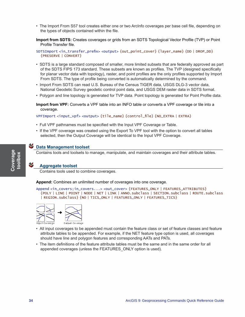
Append: Combines an unlimited number of coverages into one coverage.Append <in_covers;in_covers...> <out_cover> {FEATURES_ONLY | FEATURES_ATTRIBUTES} {POLY | LINE | POINT | NODE | NET | LINK | ANNO.subclass | SECTION.subclass | ROUTE.subclass | REGION.subclass} {NO | TICS_ONLY | FEATURES_ONLY | FEATURES_TICS}
• Allinputcoveragestobeappendedmustcontainthefeatureclassorsetoffeatureclassesandfeatureattributetablestobeappended.Forexample,iftheNETfeaturetypeoptionisused,allcoveragesshouldhavelineandpolygonfeaturesandcorrespondingAATsandPATs.
• Theitemdefinitionsofthefeatureattributetablesmustbethesameandinthesameorderforallappendedcoverages(unlesstheFEATURES_ONLYoptionisused).

Coverage toolbox
35
Composite Features toolset Contains tools to create or convert regions within a coverage and to convert line features to routes.
Line Coverage to Region: Converts arcs to preliminary regions in a new or existing coverage or appends preliminary regions to an existing region subclass.
RegionClass <in_cover> {out_cover} <out_subclass> {in_region_item} {out_region_item} {selection_file} {MULTIRING | SINGLERING}
• TheinputcoveragemusthaveanAATtospecifytheinputregionitem.• Thearcsineachgroup,whicharedeterminedbytheuniquevalueoftheinputregionitem,mustformclosedloops.Whentheinputregionitemisnotspecified,eacharcintheinputcoveragebecomesapreliminary region and should form a closed loop.
• Ifaselectionfileisnotspecified,allarcsareselectedandavailableforgroupingintoregions.However,arcs in the input coverage that are already part of one or more fully structured regions are not available for appending to the subclass since they may not form closed rings when grouped.
Line Coverage to Route: Creates a route system by creating whole arc sections for each arc in the input coverage. It can also be used to append arcs to an existing route system.
ArcRoute <in_cover> <out_route_system> {in_route_item} {out_route_item} {measure_item} {UL | UR | LL | LR} {BLANK | NO_BLANK}
• Createsaroutesystemfromlinesorappendslinestoaroutesystem.Itgroupslinesthataretopologicallyconnectedandhaveuniquevaluesfortheinputitemtocreatetheroutesystem.Theuniquevaluesoftheinputitemarealwayswrittentotheoutputitemintherouteattributetable(RAT);these values help identify routes once they have been created.
• Whenappendingroutestoanexistingroutesystem,outputrouteitemmustbethenameofanexistingitem on the route attribute table of the route system. The tool will append a section to an existing routeforeveryinputarchavinganinputitemequaltoanoutputrouteitemintherouteattributetable,provided the input arcs are topologically connected to the route being appended. The measure item on the original part of the route being appended is updated based on the measures assigned to the new sectionsandthespecifiedstartingnode.Forthosegroupsofarcshavingvaluesfortheinputrouteitemnotfoundintheoutputrouteitem,anewrouteiscreated.
Polygon Coverage to Region: Converts a polygon coverage to a region subclass. Each polygon in the in_coverbecomesaregionoftheoutputsubclass.
PolyRegion <in_cover> <out_cover> <out_subclass>
• PolygonCoverageToRegioncanbeusedonaninputcoveragethatdoesnothavearctopology;however,theinputcoveragemusthavepolygontopology.
• Thetoolbuildsregiontopologyfortheoutputsubclass.Topologyintheinputcoverageismaintainedinthe output coverage.
• Whentheoutputcoverageisthesameastheinputcoverage,thesubclassiscreatedinthatcoverage.
Region to Polygon Coverage:ConvertsaregionsubclassintoapolygoncoverageandcreatesanINFOtable containing overlapping region information.
RegionPoly <in_cover> <out_cover> <in_subclass> {out_table}
• AllitemsintheregionsubclasspolygonattributetablearemaintainedintheoutputcoveragePAT.

Cov
erag
e to
olbo
x
36 ArcGIS 9: Geoprocessing Commands Quick Reference Guide
• TheoutputcoveragePATcontainsonlytheattributesofthefirstregionassociatedwitheachpolygon.Valuesofzeroindicatevoidareasinwhichthesubclassdoesnotexist.
• Theattributesofthesecondtothenthregionsassociatedwitheachpolygonarestoredintheoutputtable.
• Ifonlyoneregionisassociatedwitheachpolygon(aplanarregionsubclass),thentheoutputtabledoesnotneedtobespecified.However,anoutputtablemustbespecifiedwhenusingnonplanarregionsubclasses.
Generalization toolset Contains tools to derive data with less detail and complexity from coverage features.
Aggregate Polygons: Combines disjointed and adjacent polygons into new area features based on a distance.
AggregatePolygons <in_cover> <out_cover> <cell_size> <distance> {NON_ORTHOGONAL | ORTHOGONAL}
• ThistoolinvolvesGRIDfunctionsandrequirestheArcGISSpatialAnalystextensionsoftwarelicense.• Theinputcoveragemusthaveapolygontopology.• Duetothepossibilityofcreatingoverlappingboundaries,preliminaryregionsareusedastheresultingfeatures.Tocreatefullybuiltregionsfromthepreliminaryregions,usetheCleantoolwiththePOLYoption on the output coverage.
Collapse Dual Lines to Centerline:Derivescenterlines(singlelines)fromdual-linefeatures,suchasroadcasings,basedonspecifiedwidthtolerances.
CollapseDualLineToCenterline <in_cover> <out_cover> <maximum_width> {minimum_width}
• Inadditiontothestandarditems,theoutputcoverageAATwillcontainthefollowingfivenewitems:• LTYPE—Containsalinetypevalueof:
1 centerlines2 unused lines and outlines of complicated intersections3 partition lines
• LL#—Carriestheleftsourcearcrecordnumber.• RL#—Carriestherightsourcearcrecordnumber.• L-ID—CarriestheleftsourcearcuserID.• R-ID—CarriestherightsourcearcuserID.

Coverage toolbox
37
• Thevaluesforitem_width,output_width,anditem_typeintheitemdefinitionforalltheseitemsare4,5,andB.
Dissolve: Mergesadjacentpolygons,lines,orregionsthathavethesamevalueforaspecifieditem.Dissolve <in_cover> <out_cover> <dissolve_item> {POLY | LINE | NET | REGION.subclass}
• Dissolveisusedtocreateasimplifiedcoveragefromonethatismorecomplex.Althoughtheinputcoveragemaycontaininformationconcerningmanyfeatureattributes,theoutputcoveragecontainsinformation only about the dissolve item.
• ThemergingofpolygonswithDissolveisthecounterpartofintersectingpolygonsinoverlays.Dissolvewill remove the boundaries.
• WiththePOLYoption,Dissolvewillremovedanglingarcsandpseudonodes.TheoutputcoveragePATwiththePOLYoptionortheoutputcoverageAATwiththeLINEoptionwillonlycontainthedissolveitembutnoadditionalattributes.If#ALLisusedasthedissolveitem,theninputcoverageitemdefinitionsanddataarepreservedintheoutputcoveragebutUser-IDswillbealtered.
Eliminate: Merges selected polygons with neighboring polygons that have the largest shared border between them or the largest area.
Eliminate <in_cover> <out_cover> <info_express;info_express...> {NO_KEEP_EDGE | KEEP_EDGE} {POLY | LINE} {selection_file} {BORDER | AREA}
• Onlytheselectedsetofpolygonsorlineswillbeeliminated.PolygonsthatborderthebackgroundpolygonwillnotbeeliminatedwhenKEEP_EDGEisspecified.
• ForthePOLYoption,anarcwithanegativeUser-IDwillneverbeeliminated,evenifit’sthelongestarcinaselectedpolygon.Whenthishappens,thenextlongestarciseliminatedunlessit’salongthecoverageboundarywhentheKeeppolygonboundaryoptionisselected(KEEP_EDGE).
• UseofindexeditemscanspeeduplogicalfeatureselectioninEliminate.SeeIndexItemfordetails.
Find Conflicts: Searchesaregioncoverageforoverlappingandcloselyspacedbuildings,basedonaspecifieddistance,andrecordstheoccurrences.
FindConflicts <in_cover> <out_cover> <conflict_distance>
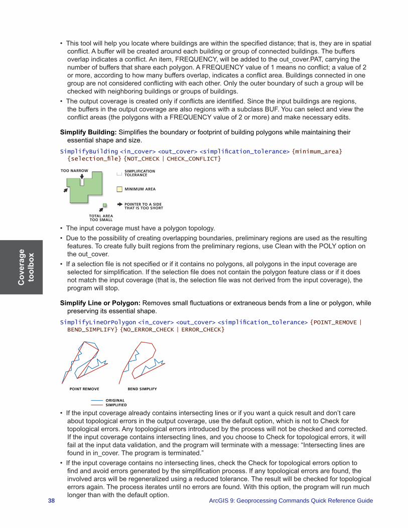
Cov
erag
e to
olbo
x
38 ArcGIS 9: Geoprocessing Commands Quick Reference Guide
• Thistoolwillhelpyoulocatewherebuildingsarewithinthespecifieddistance;thatis,theyareinspatialconflict.Abufferwillbecreatedaroundeachbuildingorgroupofconnectedbuildings.Thebuffersoverlapindicatesaconflict.Anitem,FREQUENCY,willbeaddedtotheout_cover.PAT,carryingthenumberofbuffersthatshareeachpolygon.AFREQUENCYvalueof1meansnoconflict;avalueof2ormore,accordingtohowmanybuffersoverlap,indicatesaconflictarea.Buildingsconnectedinonegrouparenotconsideredconflictingwitheachother.Onlytheouterboundaryofsuchagroupwillbechecked with neighboring buildings or groups of buildings.
• Theoutputcoverageiscreatedonlyifconflictsareidentified.Sincetheinputbuildingsareregions,thebuffersintheoutputcoveragearealsoregionswithasubclassBUF.Youcanselectandviewtheconflictareas(thepolygonswithaFREQUENCYvalueof2ormore)andmakenecessaryedits.
Simplify Building:Simplifiestheboundaryorfootprintofbuildingpolygonswhilemaintainingtheiressentialshapeandsize.
SimplifyBuilding <in_cover> <out_cover> <simplification_tolerance> {minimum_area} {selection_file} {NOT_CHECK | CHECK_CONFLICT}
• Theinputcoveragemusthaveapolygontopology.• Duetothepossibilityofcreatingoverlappingboundaries,preliminaryregionsareusedastheresultingfeatures.Tocreatefullybuiltregionsfromthepreliminaryregions,useCleanwiththePOLYoptionontheout_cover.
• Ifaselectionfileisnotspecifiedorifitcontainsnopolygons,allpolygonsintheinputcoverageareselectedforsimplification.Iftheselectionfiledoesnotcontainthepolygonfeatureclassorifitdoesnotmatchtheinputcoverage(thatis,theselectionfilewasnotderivedfromtheinputcoverage),theprogram will stop.
Simplify Line or Polygon: Removessmallfluctuationsorextraneousbendsfromalineorpolygon,whilepreserving its essential shape.
SimplifyLineOrPolygon <in_cover> <out_cover> <simplification_tolerance> {POINT_REMOVE | BEND_SIMPLIFY} {NO_ERROR_CHECK | ERROR_CHECK}
• Iftheinputcoveragealreadycontainsintersectinglinesorifyouwantaquickresultanddon’tcareabouttopologicalerrorsintheoutputcoverage,usethedefaultoption,whichisnottoCheckfortopological errors. Any topological errors introduced by the process will not be checked and corrected. Iftheinputcoveragecontainsintersectinglines,andyouchoosetoCheckfortopologicalerrors,itwillfailattheinputdatavalidation,andtheprogramwillterminatewithamessage:“Intersectinglinesarefoundinin_cover.Theprogramisterminated.”
• Iftheinputcoveragecontainsnointersectinglines,checktheCheckfortopologicalerrorsoptiontofindandavoiderrorsgeneratedbythesimplificationprocess.Ifanytopologicalerrorsarefound,theinvolvedarcswillberegeneralizedusingareducedtolerance.Theresultwillbecheckedfortopologicalerrorsagain.Theprocessiteratesuntilnoerrorsarefound.Withthisoption,theprogramwillrunmuchlonger than with the default option.
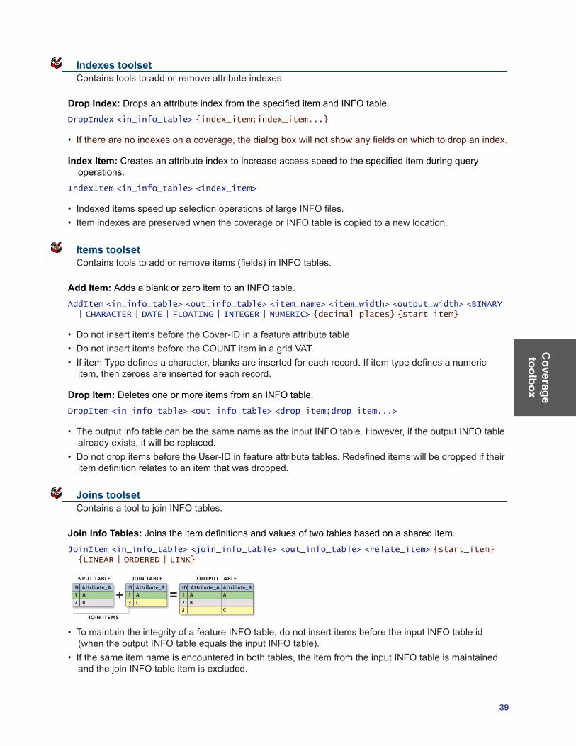
Coverage toolbox
39
Indexes toolset Contains tools to add or remove attribute indexes.
Drop Index:DropsanattributeindexfromthespecifieditemandINFOtable.DropIndex <in_info_table> {index_item;index_item...}
• Iftherearenoindexesonacoverage,thedialogboxwillnotshowanyfieldsonwhichtodropanindex.
Index Item:Createsanattributeindextoincreaseaccessspeedtothespecifieditemduringqueryoperations.
IndexItem <in_info_table> <index_item>
• IndexeditemsspeedupselectionoperationsoflargeINFOfiles.• ItemindexesarepreservedwhenthecoverageorINFOtableiscopiedtoanewlocation.
Items toolset Containstoolstoaddorremoveitems(fields)inINFOtables.
Add Item: AddsablankorzeroitemtoanINFOtable.AddItem <in_info_table> <out_info_table> <item_name> <item_width> <output_width> <BINARY | CHARACTER | DATE | FLOATING | INTEGER | NUMERIC> {decimal_places} {start_item}
• DonotinsertitemsbeforetheCover-IDinafeatureattributetable.• DonotinsertitemsbeforetheCOUNTiteminagridVAT.• IfitemTypedefinesacharacter,blanksareinsertedforeachrecord.Ifitemtypedefinesanumericitem,thenzeroesareinsertedforeachrecord.
Drop Item: DeletesoneormoreitemsfromanINFOtable.DropItem <in_info_table> <out_info_table> <drop_item;drop_item...>
• TheoutputinfotablecanbethesamenameastheinputINFOtable.However,iftheoutputINFOtablealreadyexists,itwillbereplaced.
• DonotdropitemsbeforetheUser-IDinfeatureattributetables.Redefineditemswillbedroppediftheiritemdefinitionrelatestoanitemthatwasdropped.
Joins toolset ContainsatooltojoinINFOtables.
Join Info Tables: Joinstheitemdefinitionsandvaluesoftwotablesbasedonashareditem.JoinItem <in_info_table> <join_info_table> <out_info_table> <relate_item> {start_item} {LINEAR | ORDERED | LINK}
• TomaintaintheintegrityofafeatureINFOtable,donotinsertitemsbeforetheinputINFOtableid(whentheoutputINFOtableequalstheinputINFOtable).
• Ifthesameitemnameisencounteredinbothtables,theitemfromtheinputINFOtableismaintainedandthejoinINFOtableitemisexcluded.

Cov
erag
e to
olbo
x
40 ArcGIS 9: Geoprocessing Commands Quick Reference Guide
• Thespeedofexecutionwilldependontheorganizationofthefilesbeingjoined.Ingeneral,LINKisthefastestmatchingoperation,thenLINEARwithanindexedrelateitem,thenORDERED.Althoughitisthefastestoption,LINKcannotbeappliedtomostcases.
Projections toolset Contains tools to set a projection or reproject or transform a coverage.
Define Projection: Createsormodifiesthecoordinatesysteminformation(includingprojectionparameters,suchasdatumandspheroid)storedinthecoverage’sprojectiondefinitionfile(.prj).
DefineProjection <in_cover> <projection_file>
• Thiscommandcanbeusediftheinputdatasetorfeatureclassdoesnothaveaprojectiondefined.Iftheinputdatasetorfeatureclassalreadyhasaprojectiondefined,awarningwillberaisedbutthetoolwill execute successfully.
• DefineProjectionwillnotchangethecoordinatesoftheoutputdataset.Toprojectadatasetfromoneprojectiontoanother,youmustusetheProjectcommand.
Project: Changes the coordinate system of a coverage including its datum or spheroid.Project <in_cover> <out_cover> <projection_file>
• Itcanconvertadatasetfromasphericalcoordinatesystemwithangularunits(suchasGeographic)toaplanarcoordinatesystemwithlinearunits.MostCoveragetools,amongthemBuildandClean,assumeyouhaveaplanar,two-dimensionaldataset.Soifyourdatasetisinageographiccoordinatesystemindecimaldegrees(DD,angularunits),theProjecttoolprojectsyourdatasettoanysuitableprojectedcoordinatesysteminlinearunits(metersorfeet).
• Outputprojectioninformationcanbespecifiedusingaprojectionfileorfromanemptyoutputcoverage.Theprojectionfilemustcontainbothinputandoutputprojectiondefinitions.Useofaprojectionfilewilloverrideanyprojectioninformationstoredinthedata’s.prjfile.
Transform: Moves all features in the coverage based on a set of from and to control points.Transform <in_cover> <out_cover> {AFFINE | PROJECTIVE | SIMILARITY}
• Theoutputcoveragemustalreadyexistwithaticfilecontainingx,ycoordinatesforatleasttwointhedesiredlocationandunits.Exceptforthetics,anyexistingfeaturesintheoutputcoveragewillbereplaced by features from the input coverage.
• Theinputcoverageticfileandtheoutputcoverageticfilemustcontainatleasttwocoveragesthathavethe same Tic-IDs and represent corresponding locations in both coverages. The two coverages do not have to have identical tics; only those tics whose IDs are common to both coverages will be used in the transformation.

Coverage toolbox
41
Tables toolset Contains tools used for editing the associated attribute tables.
Add XY Coordinates: Calculatesandaddsx,ycoordinatesoflabelsorpointstothecoveragePATorx,ycoordinates of nodes to the coverage NAT.
AddXY <in_cover> {POINT | NODE}
• IftheitemsX-COORDandY-COORDalreadyexist,theywillbeoverwritten.• IfthepointornodelocationsaremovedafterusingAddXYCoordinates,theX-COORDandY-COORDvalueswillnotrepresentthenewlocations.Toupdatetheirvaluestothenewlocation,rerunthetool.ThevaluesforX-COORDandY-COORDarenotmodifiedbyothertools,suchasProjectandTransform.
• Ifyourinputcoverageisinageographiccoordinatesystem,theX-COORDandY-COORDrepresentthelongitudeandlatitude,respectively.
Renumber Nodes:Updatesarc-nodetopologybyrenumberingnodesforcoveragearcsandidentifiesarcs that share the same node locations.
Renode <in_cover> {from_item} {to_item}
• Iftheinputcoveragehasanodeattributetable,RenumberNodesdoesthesamethingasBuildwiththeNODEoption.
• Allnodesintheinputcoveragearesequentiallyrenumberedstartingwith1.• Allfeatureattributetablesaswellaspolygontopologyandarc-nodetopologyaremaintainedby
Renumber Nodes.
Update IDs:UpdatesUser-IDsinacoverageaftertheyhavebeenmodifiedinafeatureattributetable.IDEdit <in_cover> <POLY | LINE | POINT | ANNO.subclass>
• Tools,suchasAddItemandCalculateField,canbeusedtoaddormodifyUser-IDsinacoverage’sfeature attribute table before Update IDs is used.
• IftheCreateLabelstoolhasbeenusedtocreatenewlabelpointsforcoveragepolygons,thepolygonUser-IDsstoredinthecoveragePATarenotequaltothenewlabelpointUser-IDs.CreateLabelsstoresthenewlabelpointsandtheirUser-IDsintheLABfile.UpdateIDsmaybeusedtochangethelabelpointUser-IDstobeequaltotheUser-IDsstoredinthePAT.

Cov
erag
e to
olbo
x
42 ArcGIS 9: Geoprocessing Commands Quick Reference Guide
Tolerances toolset Contains a tool to adjust coverage-associated tolerances.
Tolerance: Sets the tolerances associated with a coverage.Tolerance <in_cover> {FUZZY | DANGLE | TIC_MATCH | EDIT | NODESNAP | WEED | GRAIN | SNAP} {tolerance_value}
• Atolerancevalueofzerowillnotbeacceptedforthefollowingoptions:FUZZY,EDIT,NODESNAP,WEED,GRAIN,andSNAP.
• Ifnotolerancetypeisspecified,thedefaulttypeisFUZZY.
Topology toolset Contains tools used to develop the topologic relationship within a coverage.
Build: Creates or updates feature attribute tables and polygon topology.Build <in_cover> <POINT | LINE | POLY | NODE | ANNO> {anno_subclass}
• Ifacoveragefeatureattributetableexists,theadditionalitemsinthefeatureattributetablewillbeupdatedusingtheoldinternalnumberofeachofthefeaturesspecifiedastherelateitem.
• User-defineditemsinexistingfeatureattributetablesarealwaysmaintained.• WhenusingBuildwiththePOLYoption,polygonsmusthavelabelpointstoretaintheirattributes.Iftherearenoattributes,labelpointsarenotrequiredtogenerateaPAT.PolygonscontainingnolabelpointswillbeassignedaUser-IDofzero.Builddoesnotcreatepolygonlabels.
• BuildandCleanaresimilarcommandsastheyarebothusedtodefinecoveragetopology.ThebasicdifferenceisthatCleancandetectandcreateintersectionsbutBuildcannot.However,sinceBuilddoesnotuseafuzzytolerance,thecoordinateswillnotbeadjustedwhiletopologyisbeingbuilt.
Clean: Generates a coverage with correct polygon or arc-node topology.Clean <in_cover> {out_cover} {dangle_length} {fuzzy_tolerance} {POLY | LINE}
• IftheinputcoveragehaseitherPATorAATfeatureattributetables,theyareautomaticallyupdatedintheoutputcoverageforthePOLYoption.OnlytheAATwillbeupdatedwhenusingtheLINEoption.The internal number of each input coverage feature is used to relate attribute information from the input coverage feature attribute table to the output coverage to ensure that the attributes are properly joined totheoutputfeatureattributetables.FeatureUser-IDsdonothavetobeuniquetoensurethateachinput feature keeps its attributes in the output coverage.
• CleanwiththePOLYoptioncreatesoneadditionalpolygonknownasthebackgroundoruniversepolygon.Itisalwaysgivenpolygoninternalnumber1,anditsareaisthetotalsumoftheareasofallotherpolygonsinthecoverage.ItisshownasanegativeareainthePAT.
• ThedanglelengthandfuzzytolerancefortheoutputcoveragearesetandverifiedbyClean.

Coverage toolbox
43
Create Labels: Creates label points for polygons that have no labels and assigns each a User-ID.CreateLabels <in_cover> {id_base}
• Theinputcoveragemustcontainpolygontopology.• AfterCreateLabels,thepolygonUser-IDsstoredintheinputcoveragePATarenotequaltothenewlabelpointUser-IDsgeneratedbyCreateLabels.YoumustuseBuildorUpdateIDstomakethemequal.
• Ifacoveragecontainspolygonsandonlysomeofthepolygonshavelabelpoints,CreateLabelswillonly generate labels in those polygons for which no labels exist if you specify an ID base.
VPF Tile Topology:Createscross-tiletopologyforalltiledcoveragesinaVectorProductFormatdatabaselibraryorcreatestopologyforanindividualtileinaVPFlibrary.
VPFTile <VPF_library> {sig_digits} {93 | 96} {ALL | VPF_cover}
• MilitaryStandardMIL-STD-2407(June28,1996)refinesthedefinitionofcross-tiletopology.TheVPFTileTopologycommandhasbeenupdatedtomeetthenewspecification.Youmayusetheoptionalparametertochoosethe93or96VPFstandard.
• VPFTileTopologyworksonalltiledcoveragesofaVPFlibraryorasinglecoveragewithinthatlibrary.Thelastoptionalparameter,VPF_cover,allowsyoutoselectaparticularcoverageinwhichcross-tiletopologyshouldbepopulated.Itismoreefficient,however,toimplementVPFTileTopologyafterallcoveragesforalibraryhavebeenconvertedfromArcInfotoVPFformat.
Workspace Management toolset Contains a tool to manage coverages within a workspace.
Create Coverage:Createsanew,emptycoverage.Create <out_cover> {template_cover}
• Thecoordinateprecisionoftheoutputcoverageisdeterminedbytheprecisionforderivedcoveragesenvironment,regardlessofwhetherthetemplatecoverageisspecified.
• Toestablishthelocationoftheticsintheoutputcoverage,specifyatemplatecoverageoredittheoutputcoveragemanually.Youcanthenusetheoutputcoverageasthedestination(output)coverageof the transform tool.

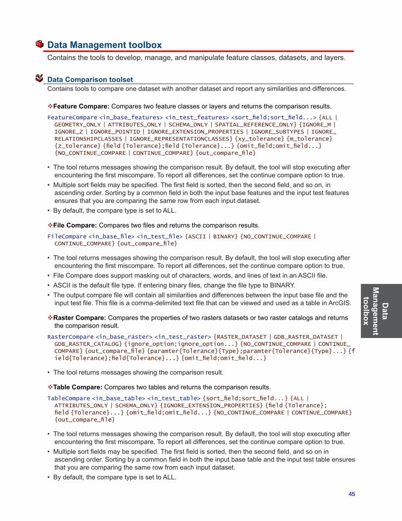
Data
Managem
ent toolbox
45
Data Management toolbox Containsthetoolstodevelop,manage,andmanipulatefeatureclasses,datasets,andlayers.
Data Comparison toolset Contains tools to compare one dataset with another dataset and report any similarities and differences.
Feature Compare: Compares two feature classes or layers and returns the comparison results.FeatureCompare <in_base_features> <in_test_features> <sort_field;sort_field...> {ALL | GEOMETRY_ONLY | ATTRIBUTES_ONLY | SCHEMA_ONLY | SPATIAL_REFERENCE_ONLY} {IGNORE_M | IGNORE_Z | IGNORE_POINTID | IGNORE_EXTENSION_PROPERTIES | IGNORE_SUBTYPES | IGNORE_RELATIONSHIPCLASSES | IGNORE_REPRESENTATIONCLASSES} {xy_tolerance} {m_tolerance} {z_tolerance} {field {Tolerance};field {Tolerance}...} {omit_field;omit_field...} {NO_CONTINUE_COMPARE | CONTINUE_COMPARE} {out_compare_file}
• Thetoolreturnsmessagesshowingthecomparisonresult.Bydefault,thetoolwillstopexecutingafterencounteringthefirstmiscompare.Toreportalldifferences,setthecontinuecompareoptiontotrue.
• Multiplesortfieldsmaybespecified.Thefirstfieldissorted,thenthesecondfield,andsoon,inascendingorder.Sortingbyacommonfieldinboththeinputbasefeaturesandtheinputtestfeaturesensures that you are comparing the same row from each input dataset.
• Bydefault,thecomparetypeissettoALL.
File Compare:Comparestwofilesandreturnsthecomparisonresults.FileCompare <in_base_file> <in_test_file> {ASCII | BINARY} {NO_CONTINUE_COMPARE | CONTINUE_COMPARE} {out_compare_file}
• Thetoolreturnsmessagesshowingthecomparisonresult.Bydefault,thetoolwillstopexecutingafterencounteringthefirstmiscompare.Toreportalldifferences,setthecontinuecompareoptiontotrue.
• FileComparedoessupportmaskingoutofcharacters,words,andlinesoftextinanASCIIfile.• ASCIIisthedefaultfiletype.Ifenteringbinaryfiles,changethefiletypetoBINARY.• Theoutputcomparefilewillcontainallsimilaritiesanddifferencesbetweentheinputbasefileandtheinputtestfile.Thisfileisacomma-delimitedtextfilethatcanbeviewedandusedasatableinArcGIS.
Raster Compare: Compares the properties of two rasters datasets or two raster catalogs and returns the comparison result.
RasterCompare <in_base_raster> <in_test_raster> {RASTER_DATASET | GDB_RASTER_DATASET | GDB_RASTER_CATALOG} {ignore_option;ignore_option...} {NO_CONTINUE_COMPARE | CONTINUE_COMPARE} {out_compare_file} {paramter{Tolerance}{Type};paramter{Tolerance}{Type}...} {field{Tolerance};field{Tolerance}...} {omit_field;omit_field...}
• Thetoolreturnsmessagesshowingthecomparisonresult.
Table Compare: Compares two tables and returns the comparison results.TableCompare <in_base_table> <in_test_table> {sort_field;sort_field...} {ALL | ATTRIBUTES_ONLY | SCHEMA_ONLY} {IGNORE_EXTENSION_PROPERTIES} {field {Tolerance}; field {Tolerance}...} {omit_field;omit_field...} {NO_CONTINUE_COMPARE | CONTINUE_COMPARE} {out_compare_file}
• Thetoolreturnsmessagesshowingthecomparisonresult.Bydefault,thetoolwillstopexecutingafterencounteringthefirstmiscompare.Toreportalldifferences,setthecontinuecompareoptiontotrue.
• Multiplesortfieldsmaybespecified.Thefirstfieldissorted,thenthesecondfield,andsooninascendingorder.Sortingbyacommonfieldinboththeinputbasetableandtheinputtesttableensuresthat you are comparing the same row from each input dataset.
• Bydefault,thecomparetypeissettoALL.

Dat
a M
anag
emen
t to
olbo
x
46 ArcGIS 9: Geoprocessing Commands Quick Reference Guide
TIN Compare:Comparestwotriangulatedirregularnetworks(TINs)andreturnsthecomparisonresults.
TinCompare <in_base_tin> <in_test_tin> {ALL | PROPERTIES_ONLY | SPATIAL_REFERENCE_ONLY} {NO_CONTINUE_COMPARE | CONTINUE_COMPARE} {out_compare_file}
• Thetoolreturnsmessagesshowingthecomparisonresult.Bydefault,thetoolwillstopexecutingafterencounteringthefirstmiscompare.Toreportalldifferences,setthecontinuecompareoptiontotrue.
• Theoutputcomparefilewillcontainallsimilaritiesanddifferencesbetweentheinputbasefeaturesandtheinputtestfeatures.Thisfileisacomma-delimitedtextfilethatcanbeviewedandusedasatableinArcGIS.Forexample,thistablecanbequeriedtoobtainalltheobjectIDvaluesforalltherowsthataredifferent.
Database toolset Contains tools that improve database performance.
Clear Workspace Cache: Clears any ArcSDE workspaces from the ArcSDE workspace cache.
ClearWorkspaceCache {in_data}
• ThistoolcanbeusedtohelpdisconnectidleArcSDEconnectionsinalongrunningapplication.• Tocleartheworkspacecachecorrectyinascript,thecalltoClearWorkspaceCache()shouldbethelastcallinyourscript,makingsuresuretoremoveallreferencestoanyobjectsthatmaybepointingtotheArcSDE workspace before calling the tool.
Compact:Reducesthesizeandoptimizestheperformanceofafileorpersonalgeodatabase.Compact <in_workspace>
• Youshouldcompactyourdatabasesonaregularbasisifyoudoalotofdataentryanddeletion.• Personalandfilegeodatabasesarestoredinbinaryfilesonyourdiskdrive.Asyouadd/remove/editdatainthesefiles,theywillbecomefragmented,resultinginadecreaseinperformance.
• Itisrecommendedthatyoucompactyourpersonalgeodatabasewhenitssizeincreasestomorethan250MB.
Compress: Compresses an ArcSDE geodatabase by removing states not referenced by a version and redundant rows.
Compress <in_workspace>
• Whenyoudeletearecordfromadatabase,itisonlymarkedasdeleted;itisnotactuallyremovedfromtheassociatedtable.Therefore,thetablewillremainthesamesizeafteryoudeleterecords.Toactuallyremovedeletedrecordsfromthedatabase,youmustcompressthedatabase.
• Toimprovedatabaseperformance,thedatabaseshouldbecompressedperiodically.• Onceadatabaseiscompressed,deletedrecordscannotberecovered.• OnlytheSDEadministratorcanperformcompression.• Aftercompressingthedatabaseoreditingthedata,theAnalyzecommandshouldbeexecutedtoupdatethedatabasestatisticsforeachdatasetorfeatureclass.Thiswillimprovedisplayandqueryperformance.
Migrate Storage:ChangeshowBLOBobjectsarestoredwithinanArcSDEgeodatabasethroughthemigrationofBLOBobjectsusingconfigurationkeywordsspecifiedintheDBTUNEtable.
MigrateStorage <in_datasets;in_datasets> <config_keyword>
• Itisrecommendedthatyoumakeabackupofthedatabeforeyoumigrateit.• BLOBsareusedtostoregeometries,attributesandrasterinformationingeodatabasetables.

Data
Managem
ent toolbox
47
• Onlycertainmigrationpathsaresupported,formoreinformationonthedatabasespecificmigrationpaths supported consult the SDE documentation.
Upgrade Spatial Reference:Upgradesalowprecisiondataset’sspatialreferencetohighprecision.UpgradeSpatialReference <input_dataset> {xy_resolution} {z_resolution} {m_resolution}
• Validinputisstand-alonefeatureclass,featuredataset,orrastercatalogwithlow-resolutionspatialreference and stored in an upgraded or current version of a personal or ArcSDE geodatabase.
Disconnected Editing toolset Contains tools to allow remote or mobile users to transfer data from a central database to remote or mobilelocations,enablinguserstooperateindependently.
Check In:ChecksinchangesmadeinacheckedoutArcSDE,file,orpersonalgeodatabasetothemaster ArcSDE geodatabase.
CheckIn <in_workspace> <dest_workspace> {NON_RECONCILE | RECONCILE}
• Youmusthavepermissiontoeditthedatayouarecheckingin.• Oncecheckedin,thechanges(edits)willbereflectedinthemastergeodatabaseandviewablebyall
users.• DatacannotbecheckedinorcheckedoutinArcView.
Check In from Delta:ChecksinageodatabasefromadeltadatabaseordeltaXMLfile.Adeltafilecontains only the changes exported from a checkout geodatabase.
CheckInDelta <in_delta_database> <dest_workspace> {NON_RECONCILE | RECONCILE}
• Insteadofcheckingineditsdirectlyfromthecheckoutgeodatabase,youcanexportthechangesonlyfromthecheckoutgeodatabasetoadeltadatabaseordeltaXMLfile.DeltadatabasesandXMLfilesare smaller than the original checkout geodatabase.
• Whenthecheck-infromthedeltadatabaseorXMLfilesucceeds,thecheckoutinthemastergeodatabase will be unregistered.
• CheckinginchangesfromadeltadatabaseorXMLfiledoesnotautomaticallyunregisterthecheckoutin the associated checkout geodatabase; this must be done manually.
Check Out:ChecksoutdatasetsfromanArcSDEgeodatabasetoanArcSDE,file,orpersonalgeodatabaseforofflineediting.
CheckOut <in_data;in_data...> <out_workspace> <out_name> <DATA | SCHEMA_ONLY> <NO_REUSE | REUSE> <RELATED | NO_RELATED>
• ThetoolacceptslayersortablesthatreferencedatafromoneArcSDEserver.Eitheraddthemtothelist in the dialog box or create a semicolon-delimited list at the command line or in a script.
• ThelayersandtablesmustreferenceversionedArcSDEfeatureclassesandtablesforwhichyouhavepermissions to edit.
• Ifthecheckoutistoapersonalgeodatabasethatdoesnotexist,onewillbecreated.
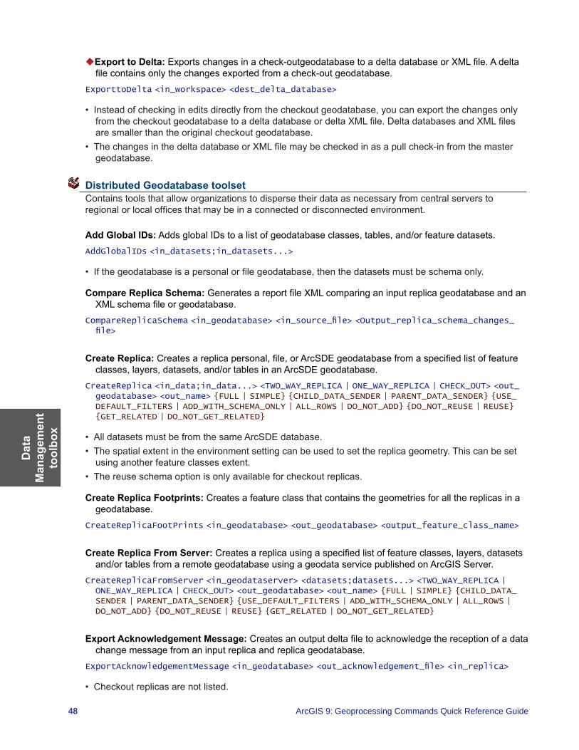
Dat
a M
anag
emen
t to
olbo
x
48 ArcGIS 9: Geoprocessing Commands Quick Reference Guide
Export to Delta:Exportschangesinacheck-outgeodatabasetoadeltadatabaseorXMLfile.Adeltafilecontainsonlythechangesexportedfromacheck-outgeodatabase.
ExporttoDelta <in_workspace> <dest_delta_database>
• Insteadofcheckingineditsdirectlyfromthecheckoutgeodatabase,youcanexportthechangesonlyfromthecheckoutgeodatabasetoadeltadatabaseordeltaXMLfile.DeltadatabasesandXMLfilesare smaller than the original checkout geodatabase.
• ThechangesinthedeltadatabaseorXMLfilemaybecheckedinasapullcheck-infromthemastergeodatabase.
Distributed Geodatabase toolset Containstoolsthatalloworganizationstodispersetheirdataasnecessaryfromcentralserverstoregionalorlocalofficesthatmaybeinaconnectedordisconnectedenvironment.
Add Global IDs:AddsglobalIDstoalistofgeodatabaseclasses,tables,and/orfeaturedatasets.AddGlobalIDs <in_datasets;in_datasets...>
• Ifthegeodatabaseisapersonalorfilegeodatabase,thenthedatasetsmustbeschemaonly.
Compare Replica Schema:GeneratesareportfileXMLcomparinganinputreplicageodatabaseandanXMLschemafileorgeodatabase.
CompareReplicaSchema <in_geodatabase> <in_source_file> <Output_replica_schema_changes_file>
Create Replica:Createsareplicapersonal,file,orArcSDEgeodatabasefromaspecifiedlistoffeatureclasses,layers,datasets,and/ortablesinanArcSDEgeodatabase.
CreateReplica <in_data;in_data...> <TWO_WAY_REPLICA | ONE_WAY_REPLICA | CHECK_OUT> <out_geodatabase> <out_name> {FULL | SIMPLE} {CHILD_DATA_SENDER | PARENT_DATA_SENDER} {USE_DEFAULT_FILTERS | ADD_WITH_SCHEMA_ONLY | ALL_ROWS | DO_NOT_ADD} {DO_NOT_REUSE | REUSE} {GET_RELATED | DO_NOT_GET_RELATED}
• AlldatasetsmustbefromthesameArcSDEdatabase.• Thespatialextentintheenvironmentsettingcanbeusedtosetthereplicageometry.Thiscanbeset
using another feature classes extent.• Thereuseschemaoptionisonlyavailableforcheckoutreplicas.
Create Replica Footprints: Creates a feature class that contains the geometries for all the replicas in a geodatabase.
CreateReplicaFootPrints <in_geodatabase> <out_geodatabase> <output_feature_class_name>
Create Replica From Server:Createsareplicausingaspecifiedlistoffeatureclasses,layers,datasetsand/or tables from a remote geodatabase using a geodata service published on ArcGIS Server.
CreateReplicaFromServer <in_geodataserver> <datasets;datasets...> <TWO_WAY_REPLICA | ONE_WAY_REPLICA | CHECK_OUT> <out_geodatabase> <out_name> {FULL | SIMPLE} {CHILD_DATA_SENDER | PARENT_DATA_SENDER} {USE_DEFAULT_FILTERS | ADD_WITH_SCHEMA_ONLY | ALL_ROWS | DO_NOT_ADD} {DO_NOT_REUSE | REUSE} {GET_RELATED | DO_NOT_GET_RELATED}
Export Acknowledgement Message:Createsanoutputdeltafiletoacknowledgethereceptionofadatachange message from an input replica and replica geodatabase.
ExportAcknowledgementMessage <in_geodatabase> <out_acknowledgement_file> <in_replica>
• Checkoutreplicasarenotlisted.

Data
Managem
ent toolbox
49
Export Data Change Message:Createsanoutputdeltafilecontainingreplicaupdatesfromaninputreplica and replica geodatabase.
ExportDataChangeMessage <in_geodatabase> <out_data_changes_file> <in_replica> <DO_NOT_SWITCH | SWITCH> <UNACKNOWLEDGED | NO_UNACKNOWLEDGED> <NEW_CHANGES | NO_NEW_CHANGES>
Export Replica Schema:CreatesanoutputXMLfilewiththeschemaofaninputone-ortwo-wayreplica.
ExportReplicaSchema <in_geodatabase> <output_replica_schema_file> <in_replica>
Import Message:Importschangesfromadeltafiletoareplicageodatabase.ImportMessage <in_geodatabase> <source_delta_file> {output_acknowledgement_file} {MANUAL | IN_FAVOR_OF_IMPORTED_CHANGES | IN_FAVOR_OF_DATABASE} {BY_OBJECT | BY_ATTRIBUTE} {DO_NOT_RECONCILE | RECONCILE}
• Afterimportingadatachangemessage,youhavetheoptiontoimmediatelyexportanacknowledgement message.
Import Replica Schema: Applies replica schema differences using an input replica geodatabase and XMLschemafileorgeodatabase.
ImportReplicaSchema <in_geodatabase> <in_source>
Re-Export Unacknowledged Messages:Createsanoutputdeltafilecontainingunacknowledgedreplicaupdates from an input one- or two-way replica geodatabase.
ReExportUnacknowledgedMessages <in_geodatabase> <output_delta_file> <in_replica> <ALL_UNACKNOWLEDGED | MOST_RECENT>
• Thiscommandisnotavailableforcheckoutreplicas.
Synchronize Changes:Synchronizesupdatesbetweentworeplicageodatabasesinadirectionspecifiedby the user.
SynchronizeChanges <geodatabase_1> <in_replica> <geodatabase_2> <BOTH_DIRECTIONS | FROM_GEODATABASE2_TO_1 | FROM_GEODATABASE1_TO_2> <IN_FAVOR_OF_GDB1 | IN_FAVOR_OF_GDB2 | MANUAL> <BY_OBJECT | BY_ATTRIBUTE> <DO_NOT_RECONCILE | RECONCILE >
• Oncecheckedin,thechanges(edits)willbereflectedinthemastergeodatabaseandviewablebyallusers.
Domains toolset Containstoolsforthemanagementofdomains,bothcodedandattribute,withinaworkspace.
Add Coded Value to Domain:Addsanewvaluetoadomain’scodedvaluelist.AddCodedValueToDomain <in_workspace> <domain_name> <code> <code_description>
• Acodedvaluedomaincanapplytoanytypeofattribute—text,numeric,date,andsoon—andspecifiesavalidsetofvaluesforanattribute.Forexample,acodedvaluelistforatextattributemightincludevalidpipematerialvalues:CL—castironpipe,DL—ductileironpipe,ACP—asbestosconcretepipe,oracodedvaluelistmightincludethenumericvaluesrepresentingvalidpipediameters:0.75—3/4″,2—2″,24—24″,and30—30″.
• Thecodedvaluedomainincludesboththeactualvaluethatisstoredinthedatabase(forexample,1forpavement)andadescriptionofwhatthecodevaluemeans(forexample,pavement).

Dat
a M
anag
emen
t to
olbo
x
50 ArcGIS 9: Geoprocessing Commands Quick Reference Guide
Assign Domain to Field:Setsthedomainforaparticularfieldandoptionallyforasubtype.AssignDomainToField <in_table> <field_name> <domain_name> {subtype_code;subtype_code...}
• Ifnosubtypeisspecified,thedomainisonlyassignedtothespecifiedfield.• Whenanattributedomainisassociatedwithatableorfeatureclass,anattributevalidationruleis
created in the database. This attribute validation rule describes and constrains the valid values of a fieldtype.
• Oneattributedomaincanbeassociatedwithmultiplefieldsinthesametable,featureclass,orsubtypeas well as in multiple tables and feature classes.
Create Domain:Createsanattributedomaininthespecifiedworkspace.CreateDomain <in_workspace> <domain_name> <domain_description> <SHORT | LONG | FLOAT | DOUBLE | TEXT | DATE> {CODED | RANGE} {DEFAULT | DUPLICATE | GEOMETRY_RATIO} {DEFAULT | SUM_VALUES | AREA_WEIGHTED}
• Codedvaluedomainssupportonlydefaultvalue,duplicatesplitpolicies,anddefaultvaluemergepolicies.
• Rangedomainssupportallsplitandmergepolicies.AfteraSplitorMergeoperation,theattributevalues of output features are calculated based on the numeric values of the input features and the specifiedsplitormergepolicy.
Delete Coded Value from Domain: Removes a value from a coded value domain.DeleteCodedValueFromDomain <in_workspace> <domain_name> <code;code...>
• TheCodeValueparameterAddValuebuttonisusedonlyinModelBuilder.InModelBuilder,wheretheprecedingtoolhasnotbeenrunoritsderiveddatadoesnotexist,theCodeValueparametermaynotbepopulatedwithvalues.TheAddValuebuttonallowsyoutoaddexpectedvaluessoyoucancompletetheDeleteCodedValueFromDomaindialogboxandcontinuetobuildyourmodel.
Delete Domain: Deletes a domain from a workspace.DeleteDomain <in_workspace> <domain_name>
• Adomaincannotbedeletedifitisassociatedwithafeatureclassortable.UsetheRemoveDomainFromFieldtooltoremovetheassociationbetweenafeatureclassortableandadomain.
Domain to Table: Creates a table from an attribute domain.DomainToTable <in_workspace> <domain_name> <out_table> <code_field> <description_field> {configuration_keyword}
• CreatingatablefromanattributedomainallowsforadditionaleditingofthetableinArcMap.Forexample,atablecouldbecreatedfromacodedvaluedomain,additionalcodevaluescouldbeaddedtothecodedvaluelist,andtheTableToDomaintoolcouldbeusedtoupdatetheoriginaldomain.
Remove Domain from Field:Removesanattributedomainassociationfromafeatureclassfield.RemoveDomainFromField <in_table> <field_name> {subtype_code;subtype_code...}
• TheRemoveDomainFromFieldfunctionistheoppositeoperationoftheAssignDomainToFieldfunction.Removingadomainfromafieldremovestheassociationbetweenafieldandanattributedomain.
• Whenadomainisremovedfromafield,theattributevalidationruleforthatfieldisremovedfromthedatabase.
Set Value for Range Domain: Sets the minimum and maximum values for an existing range domain.SetValueForRangeDomain <in_workspace> <domain_name> <min_value> <max_value>
Data
Managem
ent toolbox
51
• Arangedomainspecifiesavalidrangeofvaluesforanumericattribute.Forexample,avalidrangeofwater main pressure values might be between 50 and 75 psi.
Table to Domain: Creates or updates a coded value domain from a table.TableToDomain <in_table> <code_field> <description_field> <in_workspace> <domain_name> <domain_description> <APPEND | REPLACE>
Feature Class toolset Containstoolsdesignedtoperformbasicfeatureclassmanagementincludingcreating,appending,integrating,andupdatingmultiplefeatureclasses.
Append Annotation Feature Classes: Creates a new geodatabase annotation feature class by combining annotation from multiple input geodatabase annotation feature classes into a single feature class with annotation classes.
AppendAnnotation <input_features;input_features...> <output_feature_class> <reference_scale> {CREATE_CLASSES | ONE_CLASS_ONLY} {NO_SYMBOL_REQUIRED | REQUIRE_SYMBOL} {AUTO_CREATE | NO_AUTO_CREATE} {AUTO_UPDATE | NO_AUTO_UPDATE}
• Theoutputgeodatabaseannotationfeatureclasscannotberegisteredasversioned.• Ifyouselectanoutputannotationfeatureclassthatalreadyexists,thefeatureswillbeappendedinto
that feature class and the tool will project the annotation features into the destination spatial reference.
Calculate Default Cluster Tolerance: Calculates a default cluster tolerance value.CalculateDefaultClusterTolerance <in_features>
• ThevaluereturnedbyCalculateDefaultClusterToleranceisthesameclustertolerancevalueusedasa default for other geoprocessing tools.
Calculate Default Spatial Grid Index:Calculatesaspatialgridvalue,usedtoquicklylocatefeaturesina dataset that match the criteria of a spatial search.
CalculateDefaultGridIndex <in_features>
• ThespatialindexcalculatedbyCalculateDefaultSpatialGridIndexcannotbeaddedtoapersonalorfilegeodatabasebecauseitneedstheexistingindextomaintainitsintegrity.Whenyoucreateanewfeatureclassinapersonalorfilegeodatabase,youcanspecifyaspatialindex.
• SpatialgridindexescanbeaddedtoArcSDEgeodatabasefeatureclassesusingAddSpatialIndex.
Create Feature Class:Createsanew,emptyfeatureclass.CreateFeatureClass <out_path> <out_name> <POLYGON | POINT | MULTIPOINT | POLYLINE> {template;template...} {DISABLED | SAME_AS_TEMPLATE | ENABLED} {DISABLED | SAME_AS_TEMPLATE | ENABLED} {spatial_reference} {configuration_keyword} {spatial_grid_1} {spatial_grid_2} {spatial_grid_3}
• Thetypeofafeatureclasscreateddependsontheformatofthepathnamespecified:ageodatabasefeatureclassforArcSDEandpersonalorfilegeodatabasepathnamesorashapefilefeatureclassforafilesystemfolder.
• TheCreateFeatureClassfunctiononlycreatessimplefeatureclasses.Customfeatureclasses(annotation,dimensions,andsoon)canbecreatedinArcCatalog.
Create Fishnet:Createsafishnetofrectangularcells.CreateFishnet <out_feature_class> <origin_coord> <y_axis_coord> <cell_width> <cell_height> <number_rows> <number_columns> {corner_coord} {LABELS | NO_LABELS} {template}
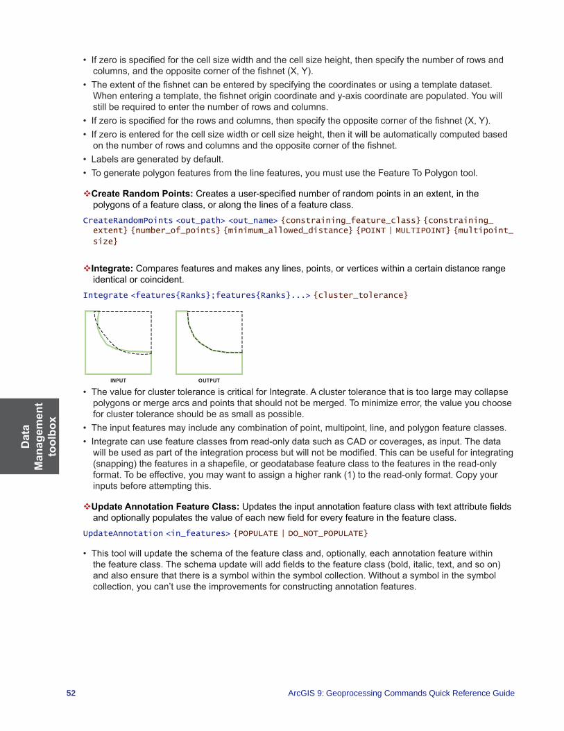
Dat
a M
anag
emen
t to
olbo
x
52 ArcGIS 9: Geoprocessing Commands Quick Reference Guide
• Ifzeroisspecifiedforthecellsizewidthandthecellsizeheight,thenspecifythenumberofrowsandcolumns,andtheoppositecornerofthefishnet(X,Y).
• Theextentofthefishnetcanbeenteredbyspecifyingthecoordinatesorusingatemplatedataset.Whenenteringatemplate,thefishnetorigincoordinateandy-axiscoordinatearepopulated.Youwillstillberequiredtoenterthenumberofrowsandcolumns.
• Ifzeroisspecifiedfortherowsandcolumns,thenspecifytheoppositecornerofthefishnet(X,Y).• Ifzeroisenteredforthecellsizewidthorcellsizeheight,thenitwillbeautomaticallycomputedbasedonthenumberofrowsandcolumnsandtheoppositecornerofthefishnet.
• Labelsaregeneratedbydefault.• Togeneratepolygonfeaturesfromthelinefeatures,youmustusetheFeatureToPolygontool.
Create Random Points:Createsauser-specifiednumberofrandompointsinanextent,inthepolygonsofafeatureclass,oralongthelinesofafeatureclass.
CreateRandomPoints <out_path> <out_name> {constraining_feature_class} {constraining_extent} {number_of_points} {minimum_allowed_distance} {POINT | MULTIPOINT} {multipoint_
size}
Integrate:Comparesfeaturesandmakesanylines,points,orverticeswithinacertaindistancerangeidentical or coincident.
Integrate <features{Ranks};features{Ranks}...> {cluster_tolerance}
• ThevalueforclustertoleranceiscriticalforIntegrate.Aclustertolerancethatistoolargemaycollapsepolygonsormergearcsandpointsthatshouldnotbemerged.Tominimizeerror,thevalueyouchoosefor cluster tolerance should be as small as possible.
• Theinputfeaturesmayincludeanycombinationofpoint,multipoint,line,andpolygonfeatureclasses.• Integratecanusefeatureclassesfromread-onlydatasuchasCADorcoverages,asinput.Thedatawillbeusedaspartoftheintegrationprocessbutwillnotbemodified.Thiscanbeusefulforintegrating(snapping)thefeaturesinashapefile,orgeodatabasefeatureclasstothefeaturesintheread-onlyformat.Tobeeffective,youmaywanttoassignahigherrank(1)totheread-onlyformat.Copyyourinputs before attempting this.
Update Annotation Feature Class:Updatestheinputannotationfeatureclasswithtextattributefieldsandoptionallypopulatesthevalueofeachnewfieldforeveryfeatureinthefeatureclass.
UpdateAnnotation <in_features> {POPULATE | DO_NOT_POPULATE}
• Thistoolwillupdatetheschemaofthefeatureclassand,optionally,eachannotationfeaturewithinthefeatureclass.Theschemaupdatewilladdfieldstothefeatureclass(bold,italic,text,andsoon)andalsoensurethatthereisasymbolwithinthesymbolcollection.Withoutasymbolinthesymbolcollection,youcan’tusetheimprovementsforconstructingannotationfeatures.

Data
Managem
ent toolbox
53
Features toolset Containstoolstomanageandenrichfeatureclasses,suchasinspectingandcorrectingpotentialerrorswith data and creating different geometries.
Add XY Coordinates:AddsthefieldsPOINT_XandPOINT_Ytothepointinputfeaturesandcalculates their values.
AddXY <in_features>
• IfthefieldsPOINT_XandPOINT_Yfieldsalreadyexist,thevalueswillbeupdated.• IfthefeaturesaremovedafterusingAddXYCoordinates,thePOINT_XandPOINT_Yvalueswillnotrepresentthenewlocations.Toupdatetheirvaluestothenewlocation,rerunthetool.ThevaluesforPOINT_XandPOINT_Yarenotmodifiedbyothertools,suchasProject.
• AddXYCoordinateswillalsoaddPOINT_ZandPOINT_Mfieldswhentheinputfeaturesarez-andm-enabled.
Adjust 3D Z:Allowsthemodificationofallz-valuesinaz-enabledfeatureclass.Adjust3DZ <in_features> {NO_REVERSE | REVERSE} {adjust_value} {MILLIMETERS | CENTIMETERS | METERS | INCHES | FEET | YARDS | FATHOMS} {MILLIMETERS | CENTIMETERS | METERS | INCHES | FEET | YARDS | FATHOMS}
• Bathymetrydataoftenhaspositivez-values.Youmaywanttoreversethesignsofallthedatainthefeature class to make it negative.
• Z-enableddatacouldbereferencedtoaverticaldatumthatisnotappropriateforyourgeoprocessingneeds.Thistoolcouldapplyabulk-shiftofallthez-valuesinthefeatureclasstoadjustthedataeitherup or down vertically.
Check Geometry: Checks the validity of the geometries of features.CheckGeometry <in_features;in_features...> <out_table>
• Theoutputtablewillhaveonerecordforeachproblemfound.Ifnoproblemsarefound,theoutputtablewill have no records.
• Theoutputtablehasthefollowingfields:• CLASS—Thefullpathtoandnameofthefeatureclassinwhichtheproblemwasfound.• FEATURE_ID—ThefeatureIDorobjectIDforthefeaturewiththegeometryproblem.• PROBLEM—Ashortdescriptionoftheproblem.
• ThePROBLEMfieldwillcontainoneofthefollowing:shortsegment,nullgeometry,incorrectringordering,incorrectsegmentorientation,selfintersections,unclosedrings,oremptyparts.
• Formultipointfeatures,onlythenullgeometryandemptypartproblemsapply.• Forpointfeatures,onlythenullgeometryproblemapplies.
Copy Features: Copies the selected features to a new feature class.CopyFeatures <in_features> <out_feature_class> {configuration_keyword} {spatial_grid_1} {spatial_grid_2} {spatial_grid_3}

Dat
a M
anag
emen
t to
olbo
x
54 ArcGIS 9: Geoprocessing Commands Quick Reference Guide
• Theinputfeatures(geometryandattributes)willbecopiedtotheoutputfeatureclass.• Thistoolcanbeusedfordataconversionasitcanreadmanyfeatureformats(anyyoucanaddtomap)andwritetheseouttoshapefileorgeodatabase(file,personal,orArcSDE).
• Iftheoutputfeatureclassalreadyexists,itwillbeoverwritten.
Delete Features: Deletes features from the input feature class or layer.DeleteFeatures <in_features>
• Boththegeometryandtheattributeswillbedeletedfromtheaffectedfeatures.• ArcSDE,file,orpersonalgeodatabasefeatureclasses;shapefiles;andlayersofthesedatatypesare
valid input features.
Feature Envelope to Polygon: Creates polygons from the envelopes of each feature in the input feature class.
FeatureEnvelopeToPolygon <in_features> <out_feature_class> {SINGLEPART | MULTIPART}
• Validinputsareline,polygon,andannotationfeatureclasses.• Whentheenvelopeofafeatureisaninvalidpolygon(heightorwidthiszero),thepolygonwillnotbe
written to the output.• Themultipartparameterwillhavenoeffectontheresultwhentheinputisasingle-partfeature.
Feature to Line: Creates a new output line feature class from input polygon or line features.FeatureToLine <in_features;in_features...> <out_feature_class> {cluster_tolerance} {ATTRIBUTES | NO_ATTRIBUTES}
• Theattributesoftheinputfeaturesaretransferredtotheoutputfeatureclasslines.• TogetlineswithrightandleftpolygonIDsasattributesfromapolygonfeatureclass,usethePolygon
To Line tool instead.• Anoutputlinefeatureswillbecreatedforeachinputlineandeachinputpolygonboundary.Ifinputlinesorpolygonboundariescross,theoutputlineswillbesplitintodifferentfeaturesatthoselocations.
Feature to Point:Createsapointfeatureclassbasedonaninputpolygon,line,ormultipointfeatureclass.
FeatureToPoint <in_features> <out_feature_class> {CENTROID | INSIDE}

Data
Managem
ent toolbox
55
• Iftheinputfeaturesarepolygons,theCENTROIDoptionwillresultinpointsthatareatthecenterofgravityforthatpolygon.Thesemaynotactuallybeinsidethepolygon’sarea.Toinsurethatthepointcreatedisinsidethepolygon’sarea,usetheInsideoption.
• IftheinputfeaturesarelinesandtheCENTROIDoptionisused,theoutputpointswillbecoincidentwiththecenterofthefeature’senvelope(rectangularwindowthatcontainsaspecificfeature).IftheINSIDEoptionisused,thepointonthelineclosesttothecenterofthefeature’senvelopewillbeused.
Feature to Polygon: Creates a new polygon feature class from input line and/or polygon features.FeatureToPolygon <in_features;in_features...> <out_feature_class> {cluster_tolerance} {ATTRIBUTES | NO_ATTRIBUTES} {label_features}
• Theinputfeaturesmustbelinesorpolygons.• Thelabelfeaturesparameterallowsforafeatureclassoflabelattributestobeappliedtotheoutput
polygons.
Feature Vertices to Points: Creates a point feature class from the vertex locations of the input features.FeatureVerticesToPoints <in_features> <out_feature_class> {ALL | MID | START | END | BOTH_ENDS}
• Theattributesoftheinputfeaturesarecopiedtotheoutputfeatureclasspoints.• Inputfeaturescanbelinesorpolygons.
Multipart to Singlepart:Breaksanymultipartfeaturesintosinglefeatures.MultipartToSinglepart <in_features> <out_feature_class>
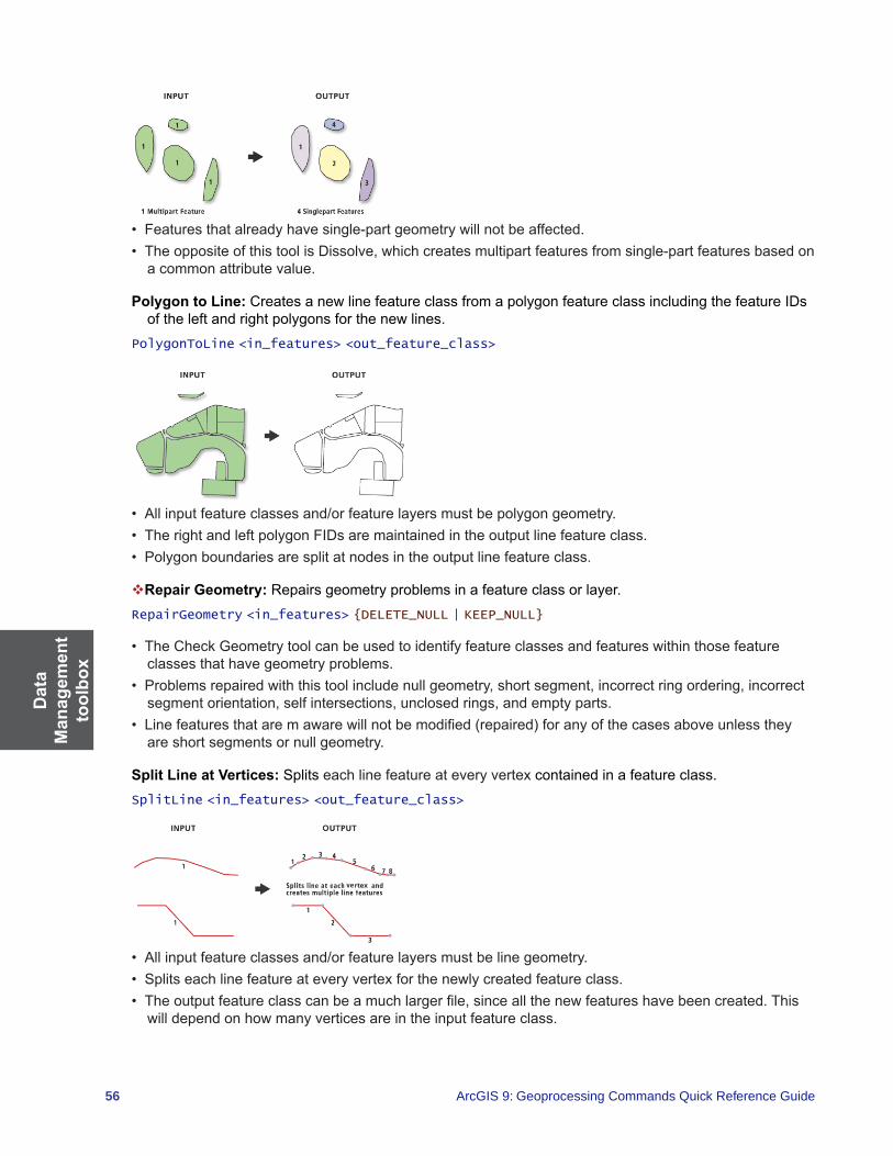
Dat
a M
anag
emen
t to
olbo
x
56 ArcGIS 9: Geoprocessing Commands Quick Reference Guide
• Featuresthatalreadyhavesingle-partgeometrywillnotbeaffected.• TheoppositeofthistoolisDissolve,whichcreatesmultipartfeaturesfromsingle-partfeaturesbasedon
a common attribute value.
Polygon to Line: Creates a new line feature class from a polygon feature class including the feature IDs of the left and right polygons for the new lines.
PolygonToLine <in_features> <out_feature_class>
• Allinputfeatureclassesand/orfeaturelayersmustbepolygongeometry.• TherightandleftpolygonFIDsaremaintainedintheoutputlinefeatureclass.• Polygonboundariesaresplitatnodesintheoutputlinefeatureclass.
Repair Geometry: Repairs geometry problems in a feature class or layer.RepairGeometry <in_features> {DELETE_NULL | KEEP_NULL}
• TheCheckGeometrytoolcanbeusedtoidentifyfeatureclassesandfeatureswithinthosefeatureclasses that have geometry problems.
• Problemsrepairedwiththistoolincludenullgeometry,shortsegment,incorrectringordering,incorrectsegmentorientation,selfintersections,unclosedrings,andemptyparts.
• Linefeaturesthataremawarewillnotbemodified(repaired)foranyofthecasesaboveunlesstheyare short segments or null geometry.
Split Line at Vertices: Splits each line feature at every vertex contained in a feature class.SplitLine <in_features> <out_feature_class>
• Allinputfeatureclassesand/orfeaturelayersmustbelinegeometry.• Splitseachlinefeatureateveryvertexforthenewlycreatedfeatureclass.• Theoutputfeatureclasscanbeamuchlargerfile,sinceallthenewfeatureshavebeencreated.This
will depend on how many vertices are in the input feature class.
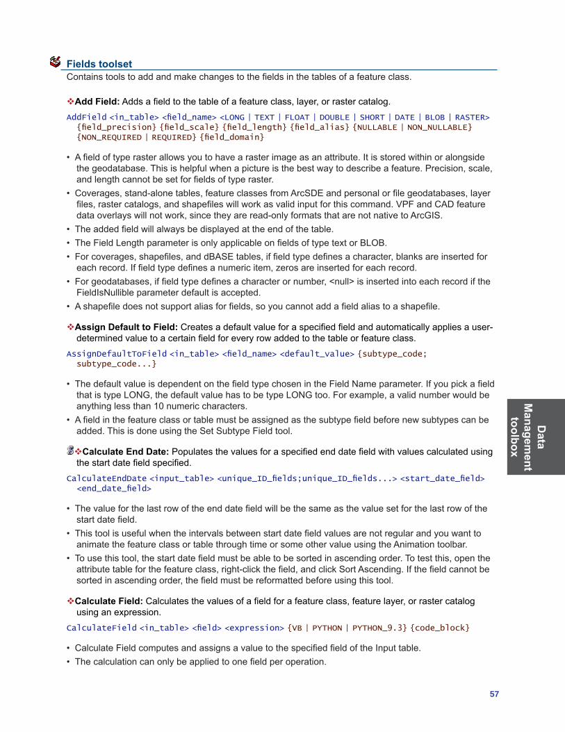
Data
Managem
ent toolbox
57
Fields toolset Containstoolstoaddandmakechangestothefieldsinthetablesofafeatureclass.
Add Field:Addsafieldtothetableofafeatureclass,layer,orrastercatalog.AddField <in_table> <field_name> <LONG | TEXT | FLOAT | DOUBLE | SHORT | DATE | BLOB | RASTER> {field_precision} {field_scale} {field_length} {field_alias} {NULLABLE | NON_NULLABLE} {NON_REQUIRED | REQUIRED} {field_domain}
• Afieldoftyperasterallowsyoutohavearasterimageasanattribute.Itisstoredwithinoralongsidethegeodatabase.Thisishelpfulwhenapictureisthebestwaytodescribeafeature.Precision,scale,andlengthcannotbesetforfieldsoftyperaster.
• Coverages,stand-alonetables,featureclassesfromArcSDEandpersonalorfilegeodatabases,layerfiles,rastercatalogs,andshapefileswillworkasvalidinputforthiscommand.VPFandCADfeaturedataoverlayswillnotwork,sincetheyareread-onlyformatsthatarenotnativetoArcGIS.
• Theaddedfieldwillalwaysbedisplayedattheendofthetable.• TheFieldLengthparameterisonlyapplicableonfieldsoftypetextorBLOB.• Forcoverages,shapefiles,anddBASEtables,iffieldtypedefinesacharacter,blanksareinsertedforeachrecord.Iffieldtypedefinesanumericitem,zerosareinsertedforeachrecord.
• Forgeodatabases,iffieldtypedefinesacharacterornumber,<null>isinsertedintoeachrecordiftheFieldIsNullibleparameterdefaultisaccepted.
• Ashapefiledoesnotsupportaliasforfields,soyoucannotaddafieldaliastoashapefile.
Assign Default to Field:Createsadefaultvalueforaspecifiedfieldandautomaticallyappliesauser-determinedvaluetoacertainfieldforeveryrowaddedtothetableorfeatureclass.
AssignDefaultToField <in_table> <field_name> <default_value> {subtype_code; subtype_code...}
• ThedefaultvalueisdependentonthefieldtypechosenintheFieldNameparameter.IfyoupickafieldthatistypeLONG,thedefaultvaluehastobetypeLONGtoo.Forexample,avalidnumberwouldbeanything less than 10 numeric characters.
• Afieldinthefeatureclassortablemustbeassignedasthesubtypefieldbeforenewsubtypescanbeadded.ThisisdoneusingtheSetSubtypeFieldtool.
Calculate End Date: Populatesthevaluesforaspecifiedenddatefieldwithvaluescalculatedusingthestartdatefieldspecified.
CalculateEndDate <input_table> <unique_ID_fields;unique_ID_fields...> <start_date_field> <end_date_field>
• Thevalueforthelastrowoftheenddatefieldwillbethesameasthevaluesetforthelastrowofthestartdatefield.
• Thistoolisusefulwhentheintervalsbetweenstartdatefieldvaluesarenotregularandyouwanttoanimate the feature class or table through time or some other value using the Animation toolbar.
• Tousethistool,thestartdatefieldmustbeabletobesortedinascendingorder.Totestthis,opentheattributetableforthefeatureclass,right-clickthefield,andclickSortAscending.Ifthefieldcannotbesortedinascendingorder,thefieldmustbereformattedbeforeusingthistool.
Calculate Field: Calculatesthevaluesofafieldforafeatureclass,featurelayer,orrastercatalogusing an expression.
CalculateField <in_table> <field> <expression> {VB | PYTHON | PYTHON_9.3} {code_block}
• CalculateFieldcomputesandassignsavaluetothespecifiedfieldoftheInputtable.• Thecalculationcanonlybeappliedtoonefieldperoperation.

Dat
a M
anag
emen
t to
olbo
x
58 ArcGIS 9: Geoprocessing Commands Quick Reference Guide
Delete Field:Deletesoneormorefieldsfromatableofafeatureclass,featurelayer,orrastercatalog.DeleteField <in_table> <drop_field;drop_field...>
• DeleteFieldcanbeusedwithanytable;ArcSDE,file,orpersonalgeodatabasefeatureclass;coverage;rastercatalog;orshapefile.
• YoucannotdeletefieldsfromnonnativedataformatsinArcGIS,suchasVPFandCADdatasets,becausetheyareread-onlyfiles.
Transpose Time Fields: Shiftsfieldsthathavetimeasafieldnameandtheirvaluesfromcolumnstorows in a table or feature class.
TransposeTimeFields <input_feature_class_or_table> <fields_to_transpose;fields_to_transpose...> <output_feature_class_or_table> <time_field_name> <value_field_name> {attribute_fields;attribute_fields...}
• Ifyouwanttheoutputtobeatable,youneedtospecifytheinputasatable.• Shapefileisnotasupportedformatforanoutputfeatureclass.Theoutputmustbeageodatabase
feature class.• ObjectID(suchasOID,FID,andsoon)andshapefieldsshouldnotbesetasattributefields.
File Geodatabase toolset Containstoolsthatconvertindividualfilegeodatabasevectorfeatureclassesandtablesintoacompressed format.
Compress File Geodatabase Data: Convertsafilegeodatabasefeatureclassfromstandardtocompressed format.
CompressFileGeodatabaseData <in_data>
• Oncecompressed,afeatureclassortableisread-onlyandcannotbeeditedormodifiedinanyway,except for changing its name and modifying attribute indexes and metadata. Compression is ideally suitedtomaturedatasetsthatdonotrequirefurtherediting.However,ifrequired,acompresseddatasetcanalwaysbeuncompressedtoreturnittoitsoriginal,read-writeformat.
• Youcancompressageodatabase,featuredataset,stand-alonefeatureclass,ortable.Whenyoucompressageodatabase,allfeatureclassesandtableswithinitcompress.Whenyoucompressafeaturedataset,allitsfeatureclassescompress.
• Youcannotindividuallycompressoruncompressafeatureclassinafeaturedatasettoproduceamixed state where some feature classes are compressed and others are not.
Uncompress File Geodatabase Data: Convertsafilegeodatabasefeatureclassortablefromcompressed to standard format.
UncompressFileGeodatabaseData <in_data> {configuration_keyword}
• Youcanuncompressageodatabase,featuredataset,stand-alonefeatureclass,ortable.Whenyouuncompressageodatabase,allfeatureclassesandtableswithinituncompress.Whenyouuncompressafeaturedataset,allitsfeatureclassesuncompress.

Data
Managem
ent toolbox
59
• Youcannotindividuallycompressoruncompressafeatureclassinafeaturedatasettoproduceamixed state where some feature classes are compressed and others are not. Compressed feature datasets allow you to add an uncompressed feature class to the feature dataset through operations suchascreatinganew,emptyfeatureclass;copyingandpasting;andimporting.However,onceyou’vefinishedaddingfeatureclasses,youshouldrecompressoruncompressthefeaturedatasetsothat all its feature classes are either compressed or uncompressed.
General toolset Contains tools allowing for aggregation of features and provides simple semantic changes.
Append: Combines multiple input datasets into an already existing target dataset.Append <inputs;inputs...> <target> {TEST | NO_TEST} {field_mapping} {subtype}
• Inputdatasetscanbepoint,line,orpolygonfeatureclasses,tables,rasters,orrastercatalogs.• UseAppendwhenyouwanttocombinetwoormoreadjacentlayersintoonelargelayerthatcontains
all their features.• Allinputfeaturesmustbeofthesamefeaturetype(allareafeatures,allline,orallpoint).
Calculate Value:Returnsavaluebasedonauser-specifiedPythonexpression.Nowavailableforalllicense levels
CalculateValue <expression> {code_block} {Variant | Address Locator | Address Locator Style | Analysis cell size | Any value | ArcMap Document | Areal unit | Boolean | CAD Drawing Dataset | Cadastral Fabric | Catalog Root | Cell Size | Composite Layer | Compression | Coordinate System | Coordinate Systems Folder | Coverage | Coverage Feature Class | Data Element | Database Connections | Dataset | Date | dBASE Table | Decimate | Disk Connection | Double | Envelope | Evaluation Scale | Extent | Feature Class | Feature Dataset | Feature Layer | Feature Set | Field | Field Info | Field Mappings | File | Folder | Formulated Raster | GeoDataServer | Geodataset | Geometric Network | Geostatistical Layer | Geostatistical Value Table | GlobeServer | GPServer | Group Layer | Horizontal factor | Image Service | Index | INFO Expression | INFO Item | INFO Table | Interop Destination Dataset | Interop Source Dataset | Layer | Layer File | Line | Linear unit | Long | M Domain | MapAlgebra Expression | MapServer | Neighborhood | Network Analyst Class FieldMap | Network Analyst Hierarchy Settings | Network Analyst Layer | Network Dataset | Network Dataset Layer | Point | Polygon | Projection File | Pyramid | Radius | Random Number Generator | Raster Band | Raster Catalog | Raster Catalog Layer | Raster Dataset | Raster Layer | Raster Statistics | Record Set | Relationship Class | Remap | Route Measure Event Properties | Schematic Dataset | Schematic Diagram | Schematic Folder | Schematic Layer | SemiVariogram | Shapefile | Spatial Reference | SQL Expression | String | Table | Table View | Terrain Layer | Text File | Tile Size | Time configuration | TIN | Tin Layer | Tool | Toolbox | Topo features | Topology | Topology Layer | Vertical factor | VPF Coverage | VPF Table | WCS Coverage | Weighted Overlay Table | Weighted Sum | Workspace | XY Domain | Z Domain}
• ExpressionscanbecreatedinastandardPythonformatonly.Otherscriptinglanguagesarenotsupported.
Copy:Copiesfeaturedatasets,featureclasses,ortablesandpastesthemtoanotherlocation.Copy <in_data> <out_data> {data_type}
• TheCopytoolcopiesdatafromonelocationandnametoanewlocationandname.

Dat
a M
anag
emen
t to
olbo
x
60 ArcGIS 9: Geoprocessing Commands Quick Reference Guide
• TheinputandoutputofCopywillbethesamedatatype.Therefore,iftheinputtypeisashapefile,theoutputtypewillalsobeshapefile.Besuretheoutputworkspacesupportstheoutputdatatype.Forexample,donottrytocopyashapefileintoageodatabase.
Delete:Deletesfeaturedatasets,featureclasses,rasters,ortables.Delete <in_data> {data_type}
• Thedatatobedeletedshouldnotbeopenanywhereontheoperatingsystem;thatis,nootherusershouldhavethefileopen.Forexample,afeatureclasscannotbedeletedifitisopeninArcMap.
• WhendeletingitemswiththeDeletetool,ancillaryfilesassociatedwiththeitemarealsodeleted.Forexamplethemetadata,projection,andindexfilesthatmayaccompanyashapefilewillbedeletediftheshapefileisdeleted.
Merge:Combinesinputfeaturesfrommultipleinputsources(ofthesamedatatype)intoasingle,new,output feature class.
Merge <inputs; inputs...> <output> {field_mappings}
• UseMergewhentherearefeaturesfrommultipleinputsourcesthatneedtobecombinedintoonefeature class.
• Inputdatasourcesneednotbeadjacent;overlapisallowed.• Thetypeofinputdata,suchaspolygonsortables,mustbethesameforallinputs.• Asingleoutputfieldcanbegeneratedfrommultipleinputfields.Thishappensifmorethanoneinputfeatureclassortablecontainsafieldofthesamename,oritcanhappenifanewfieldiscreatedandthecontentsoftheoutputfieldaregeneratedfrommultiple(differentlynamed)user-selectedfields.
• Mergeidentifiesfieldsbasedontheirname,notontheirdatatype.Inputfieldsareidentifiedbytheirnameandgroupedintoanoutputfieldofthesamename.
• Thedatatypeofanoutputfieldwilldefaulttothedatatypeofthefirstinputfield(ofthatname)itencounters. The data type may be changed manually at any time to any valid data type. All valid data types will be listed if the tools dialog box is used.
Merge Branch: Merges two or more logical branches into a single output.MergeBranch {in_values;in_values...}
• ThistoolisintendedforuseonlyinModelBuilder.• Thetoollooksatthelistofinputsvariablesandreturnsthefirstvariablethatisinthehasbeenrun
state.• Thistooloutputsavariantthatcanbeusedasthefeedbackvariabletoanyotherinputdataelementin
the model.
Rename:Changesthenameofdata,suchasfeaturedatasets,featureclasses,rasters,tables,ortoolboxes.
Rename <in_data> <out_data> {data_type}
• Theoutputnamecannotalreadyexist.• Thedatatoberenamedshouldnotbeopenanywhereontheoperatingsystem;thatis,nootherusershouldbeaccessingthedata.Forexample,afeatureclasscannotberenamedifitisopeninArcMap.

Data
Managem
ent toolbox
61
• WhenrenamingitemswiththeRenametool,ancillaryfilesassociatedwiththeitemarealsorenamed.Forexample,themetadata,projection,andindexfilesthatmayaccompanyashapefilewillalsoberenamed.
Select Data: Selects any data type on disk as input.SelectData <in_data_element> <out_data_element>
• TheSelectDatatoolisintendedforuseonlyinModelBuilder,not at the command line.• Selectingthechildfromtheparentusingthistoolenablesyoutocontinueprocessingafterperformingataskwheretheoutputdataisacontainer,suchasafeaturedataset,andthenexttoolinthemodelrequiresafeatureclass.
Generalization toolset Contains tools to derive data with less detail and complexity from a dataset.
Aggregate Polygons: Combines disjoint and adjacent polygons into new area features based on a distance.
AggregatePolygons <in_features> <out_feature_class> <aggregation_distance> {minimum_area} {minimum_hole_size} {NON_ORTHOGONAL | ORTHOGONAL}
• Theaggregationwillonlyhappenwheretwopolygonboundariesarewithinthespecifiedaggregationdistancetoeachother.Therewillbenoself-aggregation,meaningnoaggregationwithinapolygonitself where one area of its boundary is less than the distance to another or between two parts of a multipart polygon.
• Theoutputfeatureclasswillnotcontainanygeographicattributesfromthesourcefeatures.Aone-to-manyrelationshiptablewiththenameofoutput_feature_class_Tblwillbecreatedthatlinkstheaggregatedpolygonstotheirsourcepolygons.Thistablewillcontaintwofields,OUTPUT_FIDandINPUT_FID,whichholdtheaggregatedobjectIDsandtheirinputobjectIDs,respectively.Withthislink,you can derive necessary attributes for the output features using other geoprocessing tools. The link canbecomeincorrectwheneithertheinputoroutputpolygonsaremodified.
• Theoutputmaycontainoverlappingpolygonsandself-crossingboundariesandsomeconnectingzonesmaybetoonarrow;therefore,furtherinspectionandeditingmaybeneeded.
Collapse Dual Lines to Centerline:Derivescenterlines(singlelines)fromdual-linefeatures,suchasroadcasings,basedonspecifiedwidthtolerances.
CollapseDualLinesToCenterline <in_features> <out_feature_class> <maximum_width> {minimum_width}

Dat
a M
anag
emen
t to
olbo
x
62 ArcGIS 9: Geoprocessing Commands Quick Reference Guide
• Thistoolisdesignedtoworkwithfairlyregular,nearparallelpairsoflines,suchasroadcasings.Centerlineswillbecreatedonlybetweenopen-endedlines,notinsideclosedlines,whicharelikelystreet blocks.
• Centerlineswillbederivedbasedonthespecifiedwidthparameters.Adual-linefeaturewiderthanthe maximum width or narrower than the minimum width will not be centerlined. Use known road widthsifavailable.However,sincecasingsusuallybecomewideratintersections,setthemaximumwidthslightlygreaterthantheknownmaximumwidth.Youmayneedtoexperimenttofindsuitableparameters.
• Sincethetoolisnotdesignedfornaturalfeatures,suchasirregularlyshapedrivers,youmaygetunexpected results if you apply it to such features.
Dissolve:Aggregatesfeaturesbasedonspecifiedattributes.Dissolve <in_features> <out_feature_class> {dissolve_field;dissolve_field...} {field{Statistics_Type}; field{Statistics_Type}...} {MULTI_PART | SINGLE_PART} {DISSOLVE_LINES | UNSPLIT_LINES}
• Theattributesoftheaggregatedfeaturesmaybesummarizedusingastatistictype.Forexample,whenaggregatingsaleterritories,therevenueforeachfeaturewithinaterritorycouldbesummedtoobtainthetotalsalesrevenueforthatterritory(revenuesum).
• Thestatistictypeusedtosummarizeattributesisaddedtotheoutputfeatureclassasasinglefield:statistic_field.
Eliminate: Merges the selected polygons with neighboring polygons with the largest shared border or the largest area.
Eliminate <in_features> <out_feature_class> {LENGTH | AREA}
• Featurestobeeliminatedaredeterminedbyaselectedfeaturesetappliedtoapolygonlayer.TheselectedsetmustbedeterminedinapreviousstepbyusingSelectLayerbyAttribute,usingSelectLayerbyLocation,orqueryingamaplayerinArcMap.
• Onlytheselectedsetofpolygonsfromatemporaryfeaturelayerwillbeeliminated.
Simplify Building:Simplifiestheboundaryorfootprintofbuildingpolygonswhilemaintainingtheiressentialshapeandsize.
SimplifyBuilding <in_features> <out_feature_class> <simplification_tolerance> {minimum_area} {NO_CHECK | CHECK_CONFLICTS}
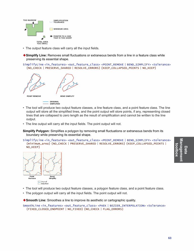
Data
Managem
ent toolbox
63
• Theoutputfeatureclasswillcarryalltheinputfields.
Simplify Line:Removessmallfluctuationsorextraneousbendsfromalineinafeatureclasswhilepreserving its essential shape.
SimplifyLine <in_features> <out_feature_class> <POINT_REMOVE | BEND_SIMPLIFY> <tolerance> {NO_CHECK | PRESERVE_SHARED | RESOLVE_ERRORS} {KEEP_COLLAPSED_POINTS | NO_KEEP}
• Thetoolwillproducetwooutputfeatureclasses,alinefeatureclass,andapointfeatureclass.Thelineoutputwillstoreallthesimplifiedlines,andthepointoutputwillstorepoints,ifany,representingclosedlinesthatarecollapsedtozerolengthastheresultofsimplificationandcannotbewrittentothelineoutput.
• Thelineoutputwillcarryalltheinputfields.Thepointoutputwillnot.
Simplify Polygon:Simplifiesapolygonbyremovingsmallfluctuationsorextraneousbendsfromitsboundary while preserving its essential shape.
SimplifyLine <in_features> <out_feature_class> <POINT_REMOVE | BEND_SIMPLIFY> <tolerance> {minimum_area} {NO_CHECK | PRESERVE_SHARED | RESOLVE_ERRORS} {KEEP_COLLAPSED_POINTS | NO_KEEP}
• Thetoolwillproducetwooutputfeatureclasses,apolygonfeatureclass,andapointfeatureclass.• Thepolygonoutputwillcarryalltheinputfields.Thepointoutputwillnot.
Smooth Line:Smoothesalinetoimproveitsaestheticorcartographicquality.SmoothLine <in_features> <out_feature_class> <PAEK | BEZIER_INTERPOLATION> <tolerance> {FIXED_CLOSED_ENDPOINT | NO_FIXED} {NO_CHECK | FLAG_ERRORS}

Dat
a M
anag
emen
t to
olbo
x
64 ArcGIS 9: Geoprocessing Commands Quick Reference Guide
• ThePolynomialApproximationwithExponentialKernel(PAEK)algorithmproducessmoothedlines;eachmayhavemoreverticesthanitssourceline.Thetoleranceyouspecifyisthelengthofa“moving”pathusedincalculatingthenewvertices.Thelongerthelength,themoresmoothedtheline.Asmalltolerancewillresultinalongprocessingtime,sobeginwitharelativelylargetoleranceandasmallnumber of lines.
• TheBezierInterpolationalgorithmdoesnotrequireanytolerance.Ifyouareusingthecommandlineorscripting,youstillneedtotypezeroinplaceofthesmooth_tolerance.
Smooth Polygon:Smoothsapolygontoimproveitsaestheticorcartographicquality.SmoothPolygon <in_features> <out_feature_class> <PAEK | BEZIER_INTERPOLATION> <tolerance> {FIXED_ENDPOINT | NOT_FIXED} {NO_CHECK | FLAG_ERRORS}
Indexes toolset Containstoolstocreate,alter,andremoveindexes.
Add Attribute Index:Addsanindextoanexistingtable,featureclass,shapefile,coverage,orattributed relationship class.
AddIndex <in_table> <fields;fields...> {index_name} {NON_UNIQUE | UNIQUE} {NON_ASCENDING | ASCENDING}
• Anattributeindexcanimprovetheperformanceofqueriesagainstyourdata.• Attributeindexesareusedwithtablesandfeatureclasses,whereasspatialindexesareusedwithgraphicalqueriesofspatialfeatureswithinfeatureclasses.
Add Spatial Index:Createsanewspatialindexforashapefile,filegeodatabasefeatureclass,oranArcSDE feature class.
AddSpatialIndex <in_features> {spatial_grid_1} {spatial_grid_2} {spatial_grid_3}
• Thiscommandwillonlyworkwithshapefiles,featureclassesinanArcSDEgeodatabase,orfeatureclassesinafilegeodatabase.
• Thespatialindexcannotbeaddedtoapersonalgeodatabasebecauseitneedstheexistingindextomaintainitsintegrity.Whenyoucreateanewfeatureclassinapersonalgeodatabase,youcanspecifya spatial index or accept the default spatial index.
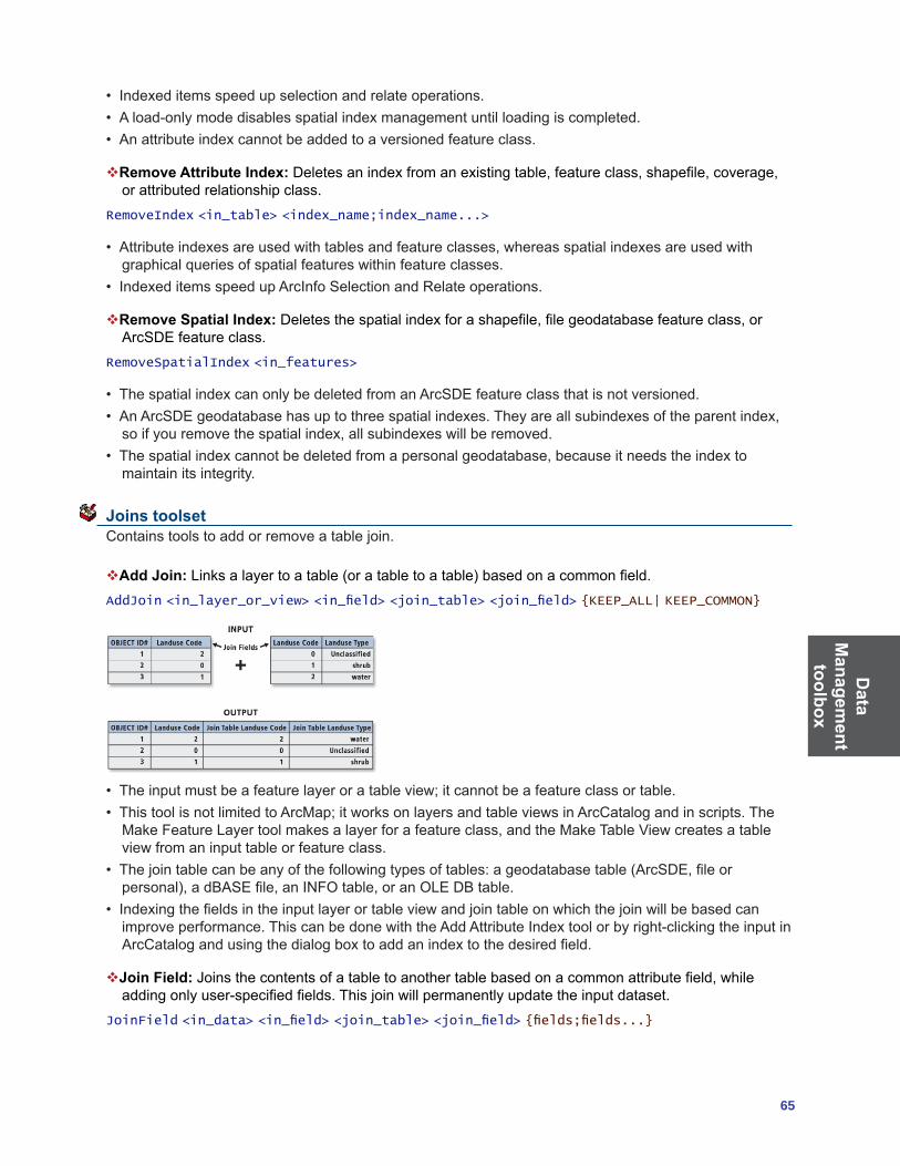
Data
Managem
ent toolbox
65
• Indexeditemsspeedupselectionandrelateoperations.• Aload-onlymodedisablesspatialindexmanagementuntilloadingiscompleted.• Anattributeindexcannotbeaddedtoaversionedfeatureclass.
Remove Attribute Index: Deletesanindexfromanexistingtable,featureclass,shapefile,coverage,or attributed relationship class.
RemoveIndex <in_table> <index_name;index_name...>
• Attributeindexesareusedwithtablesandfeatureclasses,whereasspatialindexesareusedwithgraphicalqueriesofspatialfeatureswithinfeatureclasses.
• IndexeditemsspeedupArcInfoSelectionandRelateoperations.
Remove Spatial Index:Deletesthespatialindexforashapefile,filegeodatabasefeatureclass,orArcSDE feature class.
RemoveSpatialIndex <in_features>
• ThespatialindexcanonlybedeletedfromanArcSDEfeatureclassthatisnotversioned.• AnArcSDEgeodatabasehasuptothreespatialindexes.Theyareallsubindexesoftheparentindex,soifyouremovethespatialindex,allsubindexeswillberemoved.
• Thespatialindexcannotbedeletedfromapersonalgeodatabase,becauseitneedstheindextomaintain its integrity.
Joins toolset Contains tools to add or remove a table join.
Add Join:Linksalayertoatable(oratabletoatable)basedonacommonfield.AddJoin <in_layer_or_view> <in_field> <join_table> <join_field> {KEEP_ALL| KEEP_COMMON}
• Theinputmustbeafeaturelayeroratableview;itcannotbeafeatureclassortable.• ThistoolisnotlimitedtoArcMap;itworksonlayersandtableviewsinArcCatalogandinscripts.TheMakeFeatureLayertoolmakesalayerforafeatureclass,andtheMakeTableViewcreatesatableview from an input table or feature class.
• Thejointablecanbeanyofthefollowingtypesoftables:ageodatabasetable(ArcSDE,fileorpersonal),adBASEfile,anINFOtable,oranOLEDBtable.
• Indexingthefieldsintheinputlayerortableviewandjointableonwhichthejoinwillbebasedcanimprove performance. This can be done with the Add Attribute Index tool or by right-clicking the input in ArcCatalogandusingthedialogboxtoaddanindextothedesiredfield.
Join Field:Joinsthecontentsofatabletoanothertablebasedonacommonattributefield,whileaddingonlyuser-specifiedfields.Thisjoinwillpermanentlyupdatetheinputdataset.
JoinField <in_data> <in_field> <join_table> <join_field> {fields;fields...}
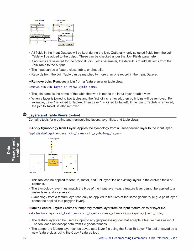
Dat
a M
anag
emen
t to
olbo
x
66 ArcGIS 9: Geoprocessing Commands Quick Reference Guide
• AllfieldsintheInputDatasetwillbekeptduringthejoin.Optionally,onlyselectedfieldsfromtheJoinTablewillbeaddedtotheoutput.ThesecanbecheckedundertheJoinFieldsparameter.
• IfnofieldsareselectedfortheoptionalJoinFieldsparameter,thedefaultistoaddallfieldsfromtheJoinTabletotheoutput.
• Theinputcanbeafeatureclass,table,orshapefile.• RecordsfromtheJoinTablecanbematchedtomorethanonerecordintheInputDataset.
Remove Join: Removes a join from a feature layer or table view.RemoveJoin <in_layer_or_view> <join_name>
• Thejoinnameisthenameofthetablethatwasjoinedtotheinputlayerortableview.• Whenalayerisjoinedtotwotablesandthefirstjoinisremoved,thenbothjoinswillberemoved.Forexample,Layer1isjoinedtoTableA.ThenLayer1isjoinedtoTableB.IfthejointoTableAisremoved,thejointoTableBisalsoremoved.
Layers and Table Views toolset Containstoolsforcreatingandmanipulatinglayers,layerfiles,andtableviews.
Apply Symbology from Layer:Appliesthesymbologyfromauser-specifiedlayertotheinputlayer.ApplySymbologyFromLayer <in_layer> <in_symbology_layer>
• Thistoolcanbeappliedtofeature,raster,andTINlayerfilesorexistinglayersintheArcMaptableofcontents.
• Thesymbologylayermustmatchthetypeoftheinputlayer(e.g.afeaturelayercannotbeappliedtoarasterlayerandviceversa).
• Symbologyfromafeaturelayercanonlybeappliedtofeaturesofthesamegeometry(e.g.apointlayercannotbeappliedtoapolygonlayer).
Make Feature Layer:Createsatemporaryfeaturelayerfromaninputfeatureclassorlayerfile.MakeFeatureLayer <in_features> <out_layer> {where_clause} {workspace} {field_info}
• Thefeaturelayercanbeusedasinputtoanygeoprocessingtoolthatacceptsafeatureclassasinput.Thetooldoesnotacceptdatafromfilegeodatabases.
• ThetemporaryfeaturelayercanbesavedasalayerfileusingtheSaveToLayerFiletoolorsavedasanewfeatureclassusingtheCopyFeaturestool.

Data
Managem
ent toolbox
67
• IfaSQLexpressionisusedbutreturnsnothing,theoutputfeaturelayerwillbeempty.
Make Image Server Layer: Creates a raster layer from an image service. MakeImageServerLayer <in_image_service> <out_image_server_layer> {template} {ID;ID...} {mosaic_method} {order_field} {order_base_value} {lock_raster_id}
• The layer that is created by the tool is temporary and will not persist after the session ends unless it is saved.
• Theoutputcanbetheentireimageserviceoraportionofit.• Theoutputcanbecreatedwithonlyasubsetofthebands.Thiswillhelpsaveontimeanddiskspace.• Themoasic_methodoptionsareonlyavailablewhentheimageservicecontainsanimageservice
created with ArcGIS Image Server.
Make Query Table:RepresentstheresultsofaSQLquerytoadatabaseinalayerortableview.MakeQueryTable <in_table;in_table...> <out_table> {USE_KEY_FIELDS | ADD_VIRTUAL_KEY_FIELD | NO_KEY_FIELD} {in_key_field;in_key_field...} {field{Alias};field{Alias}...} {where_clause}
• MakeQueryTableacceptsdatafromanArcSDEgeodatabase,apersonalgeodatabase,oranOLEDBconnection.
• Allinputfeatureclassesortablesmustbefromthesameinputworkspace.• IfaShapecolumnisaddedtothefieldlist,theresultisalayer;otherwise,itisatableview.
Make Raster Catalog Layer: Makes a temporary raster catalog layer that will be available to select as a variable while working in the same ArcMap or ArcCatalog session.
MakeRasterCatalogLayer <in_raster_catalog> <layer_name> {where_clause} {workspace} {field_info}
• Tomakeyourlayerpermanent,right-clickthelayerintheArcMaptableofcontentsandclickSaveAsLayerFileorusetheSaveToLayerFiletool.
Make Raster Layer: Makes a temporary raster dataset layer that will be available to select as a variable while working in the same ArcMap or ArcCatalog session.
MakeRasterLayer <in_raster> <out_raster_layer> {where_clause} {envelope} {Index;Index...}
• Tomakeyourlayerpermanent,right-clickthelayerintheArcMaptableofcontentsandclickSaveAsLayerFileorusetheSaveToLayerFiletool.
• Youcanindicatewhatrasterbandsfromtheinputshouldbeusedbydefininganindexvalue(s).
Make Table View: Creates a temporary table view from an input table or feature class.MakeTableView <in_table> <out_name> {where_clause} {workspace} {field_info}
• Thistooliscommonlyusedtocreateatableviewwithaselectedsetofattributesorfields.• ArcCatalogdoesnotdisplaythesetableviews,buttheycanbeusedasinputstoothergeoprocessingtoolsinthecurrentArcGISsession.OnceArcGISexits,thetablesinmemoryareremoved.
• TableviewscreatedinArcCatalogcannotbeusedinArcMap.• IfaSQLexpressionisusedbutreturnsnothing,theoutputtableviewwillbeempty.
Make WCS Layer: CreatesanimagelayerfromaWCSservice.MakeWCSLayer <in_wcs_coverage> <out_wcs_layer> {template} {ID;ID...}
• The layer that is created by the tool is temporary and will not persist after the session ends unless the document is saved.

Dat
a M
anag
emen
t to
olbo
x
68 ArcGIS 9: Geoprocessing Commands Quick Reference Guide
• Theoutputcanbetheentireimageserviceoraportionofit.• Theoutputcanbecreatedwithonlyasubsetofthebands.Thiswillhelpsaveontimeanddiskspace.
Make XY Event Layer: Creates a temporary point layer based on x and y coordinates from a source table.
MakeXYEventLayer <table> <in_x_field> <in_y_field> <out_layer> {spatial_reference}
• Thistoolallowsyoutocreatealayerbasedonxandycolumnsfromaninputtable.• Ifthetableiseditable,youwillbeabletoeditthelayer.However,youwon’tbeabletointeractively
move a point on the map; you must change the coordinates in the table.
Save to Layer File:Createsanoutputlayerfilethatreferencesgeographicdatastoredondisk.SaveToLayerFile <in_layer> <out_layer>
• Theinputlayercanbeanin-memorylayercreatedbytheMakeFeatureLayertool,alayerfilestoredondisk,orafeaturelayerinArcMap.
• Thefeaturelayerorlayerfilemayhaveasubsetofrecordsandfields.
Select Layer by Attribute:Creates,updates,orremovestheselectiononalayerortableviewusinganattributequery.
SelectLayerByAttribute <in_layer_or_view> {NEW_SELECTION | ADD_TO_SELECTION | REMOVE_FROM_SELECTION | SUBSET_SELECTION | SWITCH_SELECTION | CLEAR_SELECTION} {where_clause}
• Theinputmustbeafeaturelayeroratableview.Itcannotbeafeatureclassortable.• ThistoolisnotlimitedtoworkinginArcMap;itworksonlayersandtableviewsinArcCatalogandinscripts.TheMakeFeatureLayertoolmakesalayerforafeatureclass,andtheMakeTableViewtooldoestheequivalentforatable.
• Ifanextentoradefinitionqueryispresentontheinputlayerortableview,onlythosefeaturesorrowsthatmatchtheextentand/ordefinitionquerywillbeavailabletobeselected.
Select Layer by Location:Creates,updates,orremovesaselectionontheinputlayerbasedonspatial relationships to select features.
SelectLayerByLocation <in_layer> {INTERSECT | WITHIN_A_DISTANCE | CONTAINS | COMPLETELY_CONTAINS | CONTAINS_CLEMENTINI | WITHIN | COMPLETELY_WITHIN | WITHIN_CLEMENTINI | ARE_IDENTICAL_TO | BOUNDARY_TOUCHES | SHARE_A_LINE_SEGMENT_WITH | CROSSED_BY_THE_OUTLINE_OF | HAVE_THEIR_CENTER_IN | CONTAINED_BY} {select_features} {search_distance} {NEW_SELECTION | ADD_TO_SELECTION | REMOVE_FROM_SELECTION | SUBSET_SELECTION | SWITCH_SELECTION}
• Theinputmustbeafeaturelayeroratableview.Itcannotbeafeatureclassortable.• ThistoolisnotlimitedtoworkinginArcMap;itworksonlayersandtableviewsinArcCatalogandinscripts.TheMakeFeatureLayertoolmakesalayerforafeatureclass,andtheMakeTableViewtooldoestheequivalentforatable.
• Ifanextentoradefinitionqueryispresentontheinputlayerortableview,onlythosefeaturesorrowsthatmatchtheextentand/ordefinitionquerywillbeavailabletobeselected.
Projections and Transformations toolset Contains tools to set the projection as well as reproject or transform a dataset.
Create Custom Geographic Transformation: Creates a transformation method for converting data between two geographic coordinate systems or datums.
CreateCustomGeoTransformation <geo_transformation_name> <in_coordinate_system> <out_coordinate_system> <custom_geo_transformation>
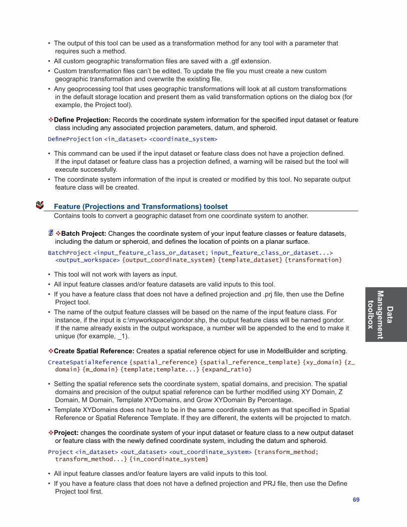
Data
Managem
ent toolbox
69
• Theoutputofthistoolcanbeusedasatransformationmethodforanytoolwithaparameterthatrequiressuchamethod.
• Allcustomgeographictransformationfilesaresavedwitha.gtfextension.• Customtransformationfilescan’tbeedited.Toupdatethefileyoumustcreateanewcustomgeographictransformationandoverwritetheexistingfile.
• Anygeoprocessingtoolthatusesgeographictransformationswilllookatallcustomtransformationsinthedefaultstoragelocationandpresentthemasvalidtransformationoptionsonthedialogbox(forexample,theProjecttool).
Define Projection: Recordsthecoordinatesysteminformationforthespecifiedinputdatasetorfeatureclassincludinganyassociatedprojectionparameters,datum,andspheroid.
DefineProjection <in_dataset> <coordinate_system>
• Thiscommandcanbeusediftheinputdatasetorfeatureclassdoesnothaveaprojectiondefined.Iftheinputdatasetorfeatureclasshasaprojectiondefined,awarningwillberaisedbutthetoolwillexecute successfully.
• Thecoordinatesysteminformationoftheinputiscreatedormodifiedbythistool.Noseparateoutputfeature class will be created.
Feature (Projections and Transformations) toolset Contains tools to convert a geographic dataset from one coordinate system to another.
Batch Project:Changesthecoordinatesystemofyourinputfeatureclassesorfeaturedatasets,includingthedatumorspheroid,anddefinesthelocationofpointsonaplanarsurface.
BatchProject <input_feature_class_or_dataset; input_feature_class_or_dataset...> <output_workspace> {output_coordinate_system} {template_dataset} {transformation}
• Thistoolwillnotworkwithlayersasinput.• Allinputfeatureclassesand/orfeaturedatasetsarevalidinputstothistool.• Ifyouhaveafeatureclassthatdoesnothaveadefinedprojectionand.prjfile,thenusetheDefineProjecttool.
• Thenameoftheoutputfeatureclasseswillbebasedonthenameoftheinputfeatureclass.Forinstance,iftheinputisc:\myworkspace\gondor.shp,theoutputfeatureclasswillbenamedgondor.Ifthenamealreadyexistsintheoutputworkspace,anumberwillbeappendedtotheendtomakeitunique(forexample,_1).
Create Spatial Reference:CreatesaspatialreferenceobjectforuseinModelBuilderandscripting.CreateSpatialReference {spatial_reference} {spatial_reference_template} {xy_domain} {z_domain} {m_domain} {template;template...} {expand_ratio}
• Settingthespatialreferencesetsthecoordinatesystem,spatialdomains,andprecision.ThespatialdomainsandprecisionoftheoutputspatialreferencecanbefurthermodifiedusingXYDomain,ZDomain,MDomain,TemplateXYDomains,andGrowXYDomainByPercentage.
• TemplateXYDomainsdoesnothavetobeinthesamecoordinatesystemasthatspecifiedinSpatialReferenceorSpatialReferenceTemplate.Iftheyaredifferent,theextentswillbeprojectedtomatch.
Project: changes the coordinate system of your input dataset or feature class to a new output dataset orfeatureclasswiththenewlydefinedcoordinatesystem,includingthedatumandspheroid.
Project <in_dataset> <out_dataset> <out_coordinate_system> {transform_method; transform_method...} {in_coordinate_system}
• Allinputfeatureclassesand/orfeaturelayersarevalidinputstothistool.• IfyouhaveafeatureclassthatdoesnothaveadefinedprojectionandPRJfile,thenusetheDefineProjecttoolfirst.

Dat
a M
anag
emen
t to
olbo
x
70 ArcGIS 9: Geoprocessing Commands Quick Reference Guide
Raster (Projections and Transformations) toolset Containstoolstosettheprojection,reproject,reorient,orrelocatearasterdataset.
Flip: Reorientstherasterbyturningitover,fromtoptobottom,alongthehorizontalaxisthroughthecenter of the raster.
Flip <in_raster> <out_raster>
• Flipflipsthegridfromtoptobottomalongthehorizontalaxisthroughthecenteroftheregion.• Thismaybeusefultocorrectrasterdatasetsthatareupsidedown.
Mirror: Reorientstherasterbyflippingit,fromlefttoright,alongtheverticalaxisthroughthecenterofthe raster.
Mirror <in_raster> <out_raster>
• Mirrorflipstherasterfromlefttorightalongtheverticalaxisthroughthecenteroftheregion.
Project Raster: Transforms a raster dataset from one projection to another.ProjectRaster <in_raster> <out_raster> <out_coorinate_system> {NEAREST | BILINEAR | CUBIC | MAJORITY} {cell_size} {geographic_transform;geographic_transform...} {registration_point} {in_coordinate_system}
• Thecoordinatesystemdefineshowyourrasterdataisprojected.• TheNEARESToption,whichperformsanearestneighborassignment,isthefastestofthethreeinterpolationmethods.Itisprimarilyusedforcategoricaldata,suchasaland-useclassification,becauseitwillnotchangethecellvalues.DonotuseNEARESTforcontinuousdata,suchaselevationsurfaces.
• TheBILINEARoption,bilinearinterpolation,determinesthenewvalueofacellbasedonaweighteddistanceaverageofsurroundingcells.TheCUBICoption,cubicconvolution,determinesthenewcellvaluebyfittingasmoothcurvethroughthesurroundingpoints.Thesearemostappropriateforcontinuousdataandmaycausesomesmoothing;also,cubicconvolutionmayresultintheoutputrastercontainingvaluesoutsidetherangeoftheinputraster.ItisnotrecommendedthatBILINEARorCUBICbeusedwithcategoricaldatabecausethecellvaluesmaybealtered.
Rescale:Scalesarasterbythespecifiedxandyscalefactors.Rescale <in_raster> <out_raster> <x_scale> <y_scale>

Data
Managem
ent toolbox
71
• Thescalefactormustbeapositivenumber.• Ascalefactorgreaterthanonemeanstheimagewillberescaledtoalargerdimension,resultinginalargerextentbecauseofalargercellsize.
• Ascalefactorlessthanonemeanstheimagewillberescaledtoasmallerdimension,resultinginasmallerextentbecauseofasmallercellsize.
Rotate: Turnstherasteraroundthespecifiedpivotpointbyanglespecifiedindegrees.Rotate <in_raster> <out_raster> <angle> {pivot_point} {NEAREST | BILINEAR | CUBIC | MAJORITY}
• Rotationis,bydefault,aroundthelowerleftcorneroftheraster.TherotationpointcanbechangedwiththeoptionalPivotPointparameter.
• Resamplingisonlydoneiftheangleisnotamultipleof90.• Therotationanglespecifiedmustbebetween0and360.
Shift: Slides the raster to a new geographic location based on x and y shift values.Shift <in_raster> <out_raster> <x_value> <y_value> {in_snap_raster}
• Thistoolishelpfulifyourrasterdatasetneedstobeshiftedtoalignwithanotherdatafile.• Thecellsizeoftheoutputrasterwillbethesameasthatoftheinputraster.• Thenumberofrowsandcolumnsintheoutputrasterwillbethesameasthoseoftheinputraster,nomatterwhatparametersarespecified.
• Thecoordinatesofthelowerleftcorneroftheoutputrasterwillbeoffsetfromtheinputrasterbythexandyshiftcoordinatevaluesspecified.
• Shiftdoesnotperformanyresamplingorwarping.
Warp: Transforms or rubber sheets a raster dataset along a set of links using a polynomial transformation.
Warp <in_raster> <source_control_points;source_control_points...> <target_control_points;target_control_points...> <out_raster> {POLYORDER1 | POLYORDER2 | POLYORDER3 | ADJUST | SPLINE} {NEAREST | BILINEAR | CUBIC | MAJORITY}
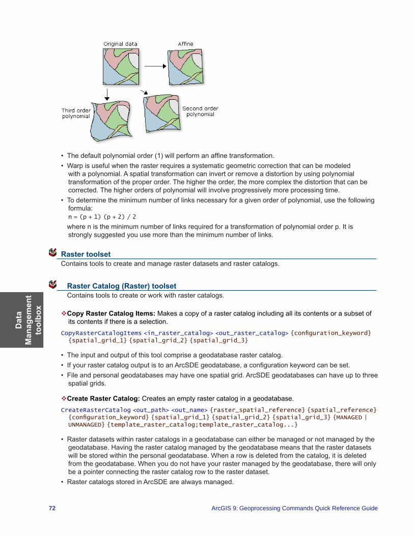
Dat
a M
anag
emen
t to
olbo
x
72 ArcGIS 9: Geoprocessing Commands Quick Reference Guide
• Thedefaultpolynomialorder(1)willperformanaffinetransformation.• Warpisusefulwhentherasterrequiresasystematicgeometriccorrectionthatcanbemodeled
with a polynomial. A spatial transformation can invert or remove a distortion by using polynomial transformationoftheproperorder.Thehighertheorder,themorecomplexthedistortionthatcanbecorrected. The higher orders of polynomial will involve progressively more processing time.
• Todeterminetheminimumnumberoflinksnecessaryforagivenorderofpolynomial,usethefollowingformula:
n = (p + 1) (p + 2) / 2
wherenistheminimumnumberoflinksrequiredforatransformationofpolynomialorderp.Itisstrongly suggested you use more than the minimum number of links.
Raster toolset Contains tools to create and manage raster datasets and raster catalogs.
Raster Catalog (Raster) toolset Contains tools to create or work with raster catalogs.
Copy Raster Catalog Items: Makes a copy of a raster catalog including all its contents or a subset of its contents if there is a selection.
CopyRasterCatalogItems <in_raster_catalog> <out_raster_catalog> {configuration_keyword} {spatial_grid_1} {spatial_grid_2} {spatial_grid_3}
• Theinputandoutputofthistoolcompriseageodatabaserastercatalog.• IfyourrastercatalogoutputistoanArcSDEgeodatabase,aconfigurationkeywordcanbeset.• Fileandpersonalgeodatabasesmayhaveonespatialgrid.ArcSDEgeodatabasescanhaveuptothree
spatial grids.
Create Raster Catalog: Creates an empty raster catalog in a geodatabase.CreateRasterCatalog <out_path> <out_name> {raster_spatial_reference} {spatial_reference} {configuration_keyword} {spatial_grid_1} {spatial_grid_2} {spatial_grid_3} {MANAGED | UNMANAGED} {template_raster_catalog;template_raster_catalog...}
• Rasterdatasetswithinrastercatalogsinageodatabasecaneitherbemanagedornotmanagedbythegeodatabase.Havingtherastercatalogmanagedbythegeodatabasemeansthattherasterdatasetswillbestoredwithinthepersonalgeodatabase.Whenarowisdeletedfromthecatalog,itisdeletedfromthegeodatabase.Whenyoudonothaveyourrastermanagedbythegeodatabase,therewillonlybe a pointer connecting the raster catalog row to the raster dataset.
• RastercatalogsstoredinArcSDEarealwaysmanaged.

Data
Managem
ent toolbox
73
• WhencreatingarastercataloginanArcSDEgeodatabase,therasterdatasetnamecannothavespaces.Youcanuseunderscorestoseparatewords.
Delete Raster Catalog Items: Deletes the raster catalogs contained in a raster catalog.DeleteRasterCatalogItems <in_raster_catalog>
• Onlygeodatabaserastercatalogsarevalidinputs.
Export Raster Catalog Paths: Creates a table listing the raster catalog paths contained in an unmanaged raster catalog. The table can be created to show all the raster catalog paths or only the broken ones.
ExportRasterCatalogPaths <in_raster_catalog> <BROKEN | ALL> <out_table>
• Thistoolcanonlybeusedforunmanagedrastercatalogs.• Theoutputofthistoolisatable,eitherinageodatabaseora.DBFfile.
Repair Raster Catalog Paths:Repairsbrokenrastercatalogpathsordeletesbrokenlinks,withinanunmanaged raster catalog.
RepairRasterCatalogPaths <in_raster_catalog> <FIX | REMOVE> {original_path} {new_path}
• Youneedtoknowthefilepathoftheoriginalrastercatalogitemlocationinordertochangeit.TheExportRasterCatalogPathstoolcanhelpyouretrievetheoriginalpathnames.
Workspace to Raster Catalog: Loads all the raster datasets that are stored within the same workspace into an existing raster catalog.
WorkspaceToRasterCatalog <in_workspace> <in_raster_catalog> {NONE | INCLUDESUBDIRECTORIES} {NONE | PROJECT_ONFLY}
• Therastercatalogmustalreadyexistforthistooltorun.• Bydefault,thespatialreferenceandgeotransformationoftherasterdatasetsarepersistedintheraster
catalog. If you want to project the raster datasets to the spatial reference of the raster column in the rastercatalogduringloading,choosetheProjectOn-the-flyoption.
Raster Dataset (Raster) toolset Contains tools to create or work with raster datasets.
Copy Raster:ConvertsarastertoaBMP,GIF,GRID,IMG,JPEG,JPEG2000,PNG,TIFF,orageodatabase raster dataset and can be used to load raster datasets into a raster catalog.
CopyRaster <in_raster> <out_raster_dataset> {configuration_keyword} {background_value} {nodata_value} {NONE | ONEBITTO8BIT} {NONE | COLORMAPTORGB} {1_BIT | 2_BIT | 4_BIT | 8_BIT_UNSIGNED | 8_BIT_SIGNED | 16_BIT_UNSIGNED | 16_BIT_SIGNED | 32_BIT_UNSIGNED | 32_BIT_SIGNED | 32_BIT_FLOAT | 64_BIT}
• Ifyouwanttoloadrasterdatasetsintoarastercatalog,youwillneedtotypeoutthefullpathnameofthe raster catalog as the output location or drag and drop the raster catalog to the output location.
Create Random Raster:Createsarandomrasterbasedonauser-specifieddistributionandextent.CreateRandomRaster <out_path> <out_name> <distribution> <raster_extent> <cellsize>
• Theuniform,integer,normal,andexponentialdistributionprocessingtimesareindependenttotheirargumentswhilethepoisson,gamma,binomial,geometric,andpascaldistributionprocessingtimescan vary considerably when arguments are changed.
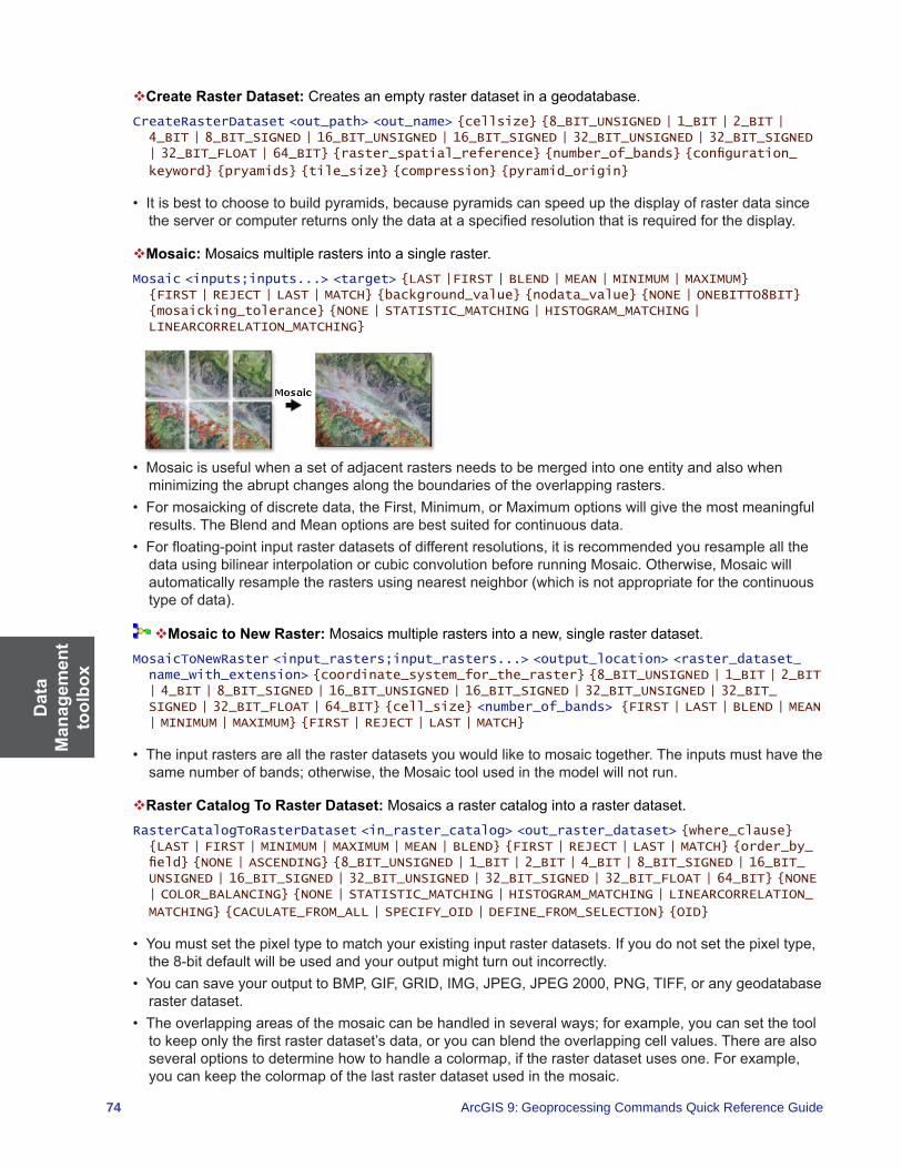
Dat
a M
anag
emen
t to
olbo
x
74 ArcGIS 9: Geoprocessing Commands Quick Reference Guide
Create Raster Dataset: Creates an empty raster dataset in a geodatabase.CreateRasterDataset <out_path> <out_name> {cellsize} {8_BIT_UNSIGNED | 1_BIT | 2_BIT | 4_BIT | 8_BIT_SIGNED | 16_BIT_UNSIGNED | 16_BIT_SIGNED | 32_BIT_UNSIGNED | 32_BIT_SIGNED | 32_BIT_FLOAT | 64_BIT} {raster_spatial_reference} {number_of_bands} {configuration_
keyword} {pryamids} {tile_size} {compression} {pyramid_origin}
• Itisbesttochoosetobuildpyramids,becausepyramidscanspeedupthedisplayofrasterdatasincetheserverorcomputerreturnsonlythedataataspecifiedresolutionthatisrequiredforthedisplay.
Mosaic: Mosaics multiple rasters into a single raster.Mosaic <inputs;inputs...> <target> {LAST |FIRST | BLEND | MEAN | MINIMUM | MAXIMUM} {FIRST | REJECT | LAST | MATCH} {background_value} {nodata_value} {NONE | ONEBITTO8BIT} {mosaicking_tolerance} {NONE | STATISTIC_MATCHING | HISTOGRAM_MATCHING | LINEARCORRELATION_MATCHING}
• Mosaicisusefulwhenasetofadjacentrastersneedstobemergedintooneentityandalsowhenminimizingtheabruptchangesalongtheboundariesoftheoverlappingrasters.
• Formosaickingofdiscretedata,theFirst,Minimum,orMaximumoptionswillgivethemostmeaningfulresults.TheBlendandMeanoptionsarebestsuitedforcontinuousdata.
• Forfloating-pointinputrasterdatasetsofdifferentresolutions,itisrecommendedyouresampleallthedatausingbilinearinterpolationorcubicconvolutionbeforerunningMosaic.Otherwise,Mosaicwillautomaticallyresampletherastersusingnearestneighbor(whichisnotappropriateforthecontinuoustypeofdata).
Mosaic to New Raster:Mosaicsmultiplerastersintoanew,singlerasterdataset.MosaicToNewRaster <input_rasters;input_rasters...> <output_location> <raster_dataset_name_with_extension> {coordinate_system_for_the_raster} {8_BIT_UNSIGNED | 1_BIT | 2_BIT | 4_BIT | 8_BIT_SIGNED | 16_BIT_UNSIGNED | 16_BIT_SIGNED | 32_BIT_UNSIGNED | 32_BIT_SIGNED | 32_BIT_FLOAT | 64_BIT} {cell_size} <number_of_bands> {FIRST | LAST | BLEND | MEAN | MINIMUM | MAXIMUM} {FIRST | REJECT | LAST | MATCH}
• Theinputrastersarealltherasterdatasetsyouwouldliketomosaictogether.Theinputsmusthavethesamenumberofbands;otherwise,theMosaictoolusedinthemodelwillnotrun.
Raster Catalog To Raster Dataset: Mosaics a raster catalog into a raster dataset.RasterCatalogToRasterDataset <in_raster_catalog> <out_raster_dataset> {where_clause} {LAST | FIRST | MINIMUM | MAXIMUM | MEAN | BLEND} {FIRST | REJECT | LAST | MATCH} {order_by_field} {NONE | ASCENDING} {8_BIT_UNSIGNED | 1_BIT | 2_BIT | 4_BIT | 8_BIT_SIGNED | 16_BIT_UNSIGNED | 16_BIT_SIGNED | 32_BIT_UNSIGNED | 32_BIT_SIGNED | 32_BIT_FLOAT | 64_BIT} {NONE | COLOR_BALANCING} {NONE | STATISTIC_MATCHING | HISTOGRAM_MATCHING | LINEARCORRELATION_
MATCHING} {CACULATE_FROM_ALL | SPECIFY_OID | DEFINE_FROM_SELECTION} {OID}
• Youmustsetthepixeltypetomatchyourexistinginputrasterdatasets.Ifyoudonotsetthepixeltype,the 8-bit default will be used and your output might turn out incorrectly.
• YoucansaveyouroutputtoBMP,GIF,GRID,IMG,JPEG,JPEG2000,PNG,TIFF,oranygeodatabaseraster dataset.
• Theoverlappingareasofthemosaiccanbehandledinseveralways;forexample,youcansetthetooltokeeponlythefirstrasterdataset’sdata,oryoucanblendtheoverlappingcellvalues.Therearealsoseveraloptionstodeterminehowtohandleacolormap,iftherasterdatasetusesone.Forexample,you can keep the colormap of the last raster dataset used in the mosaic.
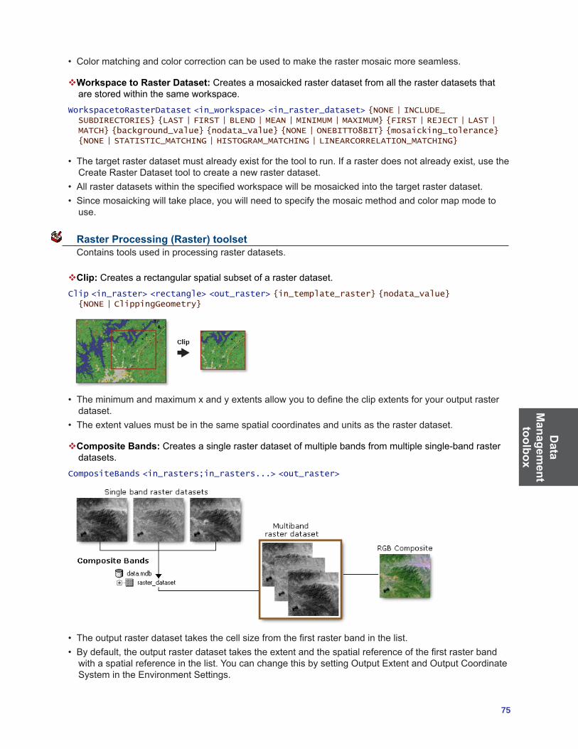
Data
Managem
ent toolbox
75
• Colormatchingandcolorcorrectioncanbeusedtomaketherastermosaicmoreseamless.
Workspace to Raster Dataset: Creates a mosaicked raster dataset from all the raster datasets that are stored within the same workspace.
WorkspacetoRasterDataset <in_workspace> <in_raster_dataset> {NONE | INCLUDE_SUBDIRECTORIES} {LAST | FIRST | BLEND | MEAN | MINIMUM | MAXIMUM} {FIRST | REJECT | LAST | MATCH} {background_value} {nodata_value} {NONE | ONEBITTO8BIT} {mosaicking_tolerance} {NONE | STATISTIC_MATCHING | HISTOGRAM_MATCHING | LINEARCORRELATION_MATCHING}
• Thetargetrasterdatasetmustalreadyexistforthetooltorun.Ifarasterdoesnotalreadyexist,usetheCreate Raster Dataset tool to create a new raster dataset.
• Allrasterdatasetswithinthespecifiedworkspacewillbemosaickedintothetargetrasterdataset.• Sincemosaickingwilltakeplace,youwillneedtospecifythemosaicmethodandcolormapmodeto
use.
Raster Processing (Raster) toolset Contains tools used in processing raster datasets.
Clip: Creates a rectangular spatial subset of a raster dataset.Clip <in_raster> <rectangle> <out_raster> {in_template_raster} {nodata_value} {NONE | ClippingGeometry}
• Theminimumandmaximumxandyextentsallowyoutodefinetheclipextentsforyouroutputrasterdataset.
• Theextentvaluesmustbeinthesamespatialcoordinatesandunitsastherasterdataset.
Composite Bands: Creates a single raster dataset of multiple bands from multiple single-band raster datasets.
CompositeBands <in_rasters;in_rasters...> <out_raster>
• Theoutputrasterdatasettakesthecellsizefromthefirstrasterbandinthelist.• Bydefault,theoutputrasterdatasettakestheextentandthespatialreferenceofthefirstrasterbandwithaspatialreferenceinthelist.YoucanchangethisbysettingOutputExtentandOutputCoordinateSystem in the Environment Settings.

Dat
a M
anag
emen
t to
olbo
x
76 ArcGIS 9: Geoprocessing Commands Quick Reference Guide
Create Ortho-Corrected Raster Dataset:Createanorthorectifiedrasterdatasetusingtherationalpolynomialcoefficients(RPC)associatedwitharasterdataset.
CreateOrthoCorrectedRasterDataset <in_raster> <out_raster_dataset> <CONSTANT ELEVATION | DEM> <constant_ elevation> <in_DEM_raster> {ZFactor} {ZOffset} {NONE | GEOID}
• Toorthocorrectarasterdataset,therastermusthaveRPCsassociatedwithit.• ADEMcanbeusedintheorthophotorectificationprocesssothattheelevationandcurvaturesofthe
earth can be taken into account.• IfaDEMisusedtoorthocorrecttherasterdataset,theconstantelevationvaluewillnotbeused.
Create Pan-Sharpened Raster Dataset:Fusesahigh-resolutionpanchromaticrasterdatasetwithalowerresolutionrasterdatasettocreateanRGBrasterwiththeresolutionofthepanchromaticraster.
CreatePansharpenedRasterDataset <in_raster> <red_channel> <green_channel> <blue_channel> {infrared_channel} <out_raster_dataset> <in_panchromatic_image> <ESRI | IHS | Brovey | SIMPLE MEAN> {red_weight} {green_weight} {blue_weight} {infrared_weight}
• Onlytheareasthatfullyoverlapwillbeaffectedbythistool.• IHSusesintensity,hue,andsaturationcolorspacefordatafusion.Broveyusesanalgorithmbasedon
spectral modeling for data fusion.
Extract Subdataset:Extractsrasterdatasetsstoredwithinasubdatasetrasterfile.ExtractSubDataset <in_raster> <out_raster> {ID;ID...}
• SubdatasetfileformatscanbeeitherHDF4orNITFfiles.• Eachsubdatasetcanhavemultiplebandsassociatedwithit.• Ifyoudonotchoosetospecifyoneormoresubdatasets,thefirstsubdatasetwillbereturned.• YoucansaveyouroutputtoBMP,GIF,GRID,IMG,JPEG,JPEG2000,PNG,TIFF,personalgeodatabase,filegeodatabase,orArcSDEgeodatabaserasterformats.
• TheGIFformatdoesnotsupportmultiband;therefore,itisnotavalidoutputformatunlessyourrasterdataset is single band.
Resample:Changesthecellsizeofagrid.Resample <in_raster> <out_raster> <cell_size> {NEAREST | BILINEAR | CUBIC | MAJORITY}
• Thelowerleftcorneroftheoutputrasterwillbethesamemapspacecoordinatelocationasthelowerleft corner of the input raster.
• Thenumbersofrowsandcolumnsintheoutputrasteraredeterminedasfollows:columns=(xmax-xmin)/cellsizerows=(ymax-ymin)/cellsize
Ifthereisanyremainderfromtheaboveequations,thenroundingofthenumberofcolumnsand/orrows is performed.
• Thecurrentenvironmentsettingsofcellsize(ifoneisspecified)andextentareappliedtotheoutput.The mask is not used.

Data
Managem
ent toolbox
77
Raster Properties (Raster) toolset Contains tools to modify raster dataset properties.
Add Colormap:Allowsyoutoaddacolormaptoarasterdataset,ifitdoesnotalreadyexist.AddColormap <in_raster> <in_template_raster>
• Thistoolallowsyoutoeithercreateoreditacolormaptableforarasterdataset.• Thecolormap,fromarasterdataset,thatalreadyexistswillbeappliedtotheinputrasterdataset.
Batch Build Pyramids: Allows you to build pyramids on multiple raster datasets.BatchBuildPyramids <input_raster_datasets;input_raster_datasets...>
• Buildingpyramidsforarasterdatasetwillimprovethedisplayperformanceoflargerasterdatasets.• Pyramidscanonlybebuiltforrasterdatasetsthatdonothaveinternalpyramids.• Pyramidscannotbebuiltforrastercatalogs,buttheycanbebuiltforeachrastercatalogmember.
Batch Calculate Statistics: Allows you to calculate statistics on multiple raster datasets.BatchCalculateStatistics <input_raster_datasets;input_raster_datasets...> {number_of_columns_to_skip} {number_of_rows_to_skip} {ignore_values;ignore_values...}
• TheinputrasterdatasetscanbeanyvalidrasterdatasetthatArcGISrecognizes.Thistoolcancalculatestatistics in a batch process.
• Calculatingstatisticsforarasterisrequiredforrenderingyourrasterdatasetwithanysortofcontraststretch.
Build Pyramids:Buildsrasterpyramidsforarasterdataset.BuildPyramids <in_raster_dataset>
• Buildingpyramidsforrasterdatasetswillhelpimprovethedisplayspeed.• Youonlyneedtobuildpyramidsonceperdataset,thenthepyramidscanbeaccessedeverytimeyou
display that raster dataset.
Build Raster Attribute Table: Adds a raster attribute table to a raster dataset or updates an existing one.
BuildRasterAttributeTable <in_raster> {NONE | OVERWRITE}
• Ifyouwanttodeleteanexistingtableandcreateanewone,checktheoverwritecheckbox.Anewraster attribute table will be created.
• IfyouhaveanexistingtableandyoudonotspecifyOVERWRITE,thetablewillbeupdated.Nofieldswillbedeleted,butthevaluesinthetablewillbeuptodate.
Calculate Statistics: Calculates statistics for a raster dataset.CalculateStatistics <in_raster_dataset> {x_skip_factor} {y_skip_fator} {ignore_values; ignore_values...}
• Calculatingstatisticsforarasterisrequiredforrenderingyourrasterdatasetwithanysortofcontraststretch.

Dat
a M
anag
emen
t to
olbo
x
78 ArcGIS 9: Geoprocessing Commands Quick Reference Guide
• Askipfactoristheparameterthatcontrolstheportionoftherasterdatasetusedwhencalculatingthestatistics.Theinputvalueindicatesthehorizontalorverticalskipfactor,whereafactorof1willuseeach pixel and a value of 2 will use every second pixel. The skip factor can only range from one to the number of columns/rows.
• Theignorevalueallowsyoutoexcludeaspecificvaluefromthecalculationofstatistics.Youmaywantto ignore a value if it is a NoData value or if it will skew your calculation.
Delete Colormap: Removes a color map that is associated with a raster dataset.DeleteColormap <in_raster>
Delete Raster Attribute Table: Removes the raster attribute table that is associated with a raster dataset.
DeleteRasterAttributeTable <in_raster>
• Theinputrasterdatasetcanonlyhaveasingleband.
Export Raster World File:Createsaworldfilebasedonthegeographicinformationofarasterdataset.Thepixelsizeandthelocationoftheupperleftpixelareextractedfortheworldfile.
ExportRasterWorldFile <in_raster_dataset>
• Theoutputworldfilewilldependonthefileformatbeingused.• Ifthetransformationcannotbeexpressedasaworldfile,thetoolwillwriteanapproximateaffinetransformationintotheworldfile,withan‘x’ontheendoftheextensionname.
Get Cell Value:Retrievesthepixelvalueataspecificx,ycoordinate.GetCellValue <in_raster> <location_point> {ID;ID...}
• Formulti-bandrasterdatasetsyoucanspecifyfromwhichbandstoretreivethecellvalue.Ifyoudonotspecifyanybands,thepixelvalueforallthebandswillbereturnedforthatlocation.
• Thistoolisusefulwhenyouneedtoacquirepixelvaluefromwithinageoprocessingmodel.InArcMap,you can use the Identify tool instead.
Get Raster Properties: Returns the properties of a raster dataset.GetRasterProperties <in_raster> {MINIMUM | MAXIMUM | MEAN | STD | UNIQUEVALUECOUNT | TOP | LEFT | RIGHT | BOTTOM | CELLSIZEX | CELLSIZEY | VALUETYPE | COLUMNCOUNT | ROWCOUNT | BANDCOUNT}
• Thepropertyreturnedwillbedisplayedinthegeoprocessingwindow.
Relationship Classes toolset Contains tools to create associations between feature classes as well as feature classes and tables.
Create Relationship Class:Createsarelationshipclasstostoreanassociationbetweenfieldsorfeatures in the origin table and the destination table.
CreateRelationshipClass <origin_table> <destination_table> <out_relationship_class> <SIMPLE | COMPOSITE> <forward_label> <backward_label> <NONE | FORWARD | BACKWARD | BOTH> <ONE_TO_ONE | ONE_TO_MANY | MANY_TO_MANY> <NONE | ATTRIBUTED> <origin_primary_key> <origin_foreign_key> {destination_primary_key} {<destination_foreign_key}
• Relationshipscanexistbetweenspatialobjects(featuresinfeatureclasses),nonspatialobjects(rowsinatable),orspatialandnonspatialobjects.
• Oncecreated,arelationshipclasscannotbemodified;youcanonlyadd,delete,orrefineitsrules.Relationship classes can be deleted and renamed using ArcCatalog in the same manner as any other object in the database.
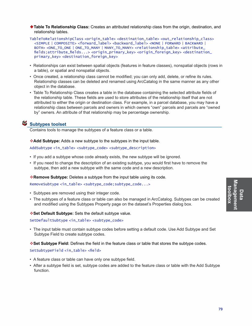
Data
Managem
ent toolbox
79
Table To Relationship Class:Createsanattributedrelationshipclassfromtheorigin,destination,andrelationship tables.
TableToRelationshipClass <origin_table> <destination_table> <out_relationship_class> <SIMPLE | COMPOSITE> <forward_label> <backward_label> <NONE | FORWARD | BACKWARD | BOTH> <ONE_TO_ONE | ONE_TO_MANY | MANY_TO_MANY> <relationship_table> <attribute_fields;attribute_fields...> <origin_primary_key> <origin_foreign_key> <destination_primary_key> <destination_foreign_key>
• Relationshipscanexistbetweenspatialobjects(featuresinfeatureclasses),nonspatialobjects(rowsinatable),orspatialandnonspatialobjects.
• Oncecreated,arelationshipclasscannotbemodified;youcanonlyadd,delete,orrefineitsrules.Relationship classes can be deleted and renamed using ArcCatalog in the same manner as any other object in the database.
• TableToRelationshipClasscreatesatableinthedatabasecontainingtheselectedattributefieldsoftherelationshiptable.Thesefieldsareusedtostoreattributesoftherelationshipitselfthatarenotattributedtoeithertheoriginordestinationclass.Forexample,inaparceldatabase,youmayhavearelationshipclassbetweenparcelsandownersinwhichowners“own”parcelsandparcelsare“ownedby”owners.Anattributeofthatrelationshipmaybepercentageownership.
Subtypes toolset Contains tools to manage the subtypes of a feature class or a table.
Add Subtype: Adds a new subtype to the subtypes in the input table.AddSubtype <in_table> <subtype_code> <subtype_description>
• Ifyouaddasubtypewhosecodealreadyexists,thenewsubtypewillbeignored.• Ifyouneedtochangethedescriptionofanexistingsubtype,youwouldfirsthavetoremovethesubtype,thenaddanewsubtypewiththesamecodeandanewdescription.
Remove Subtype: Deletes a subtype from the input table using its code.RemoveSubtype <in_table> <subtype_code;subtype_code...>
• Subtypesareremovedusingtheirintegercode.• ThesubtypesofafeatureclassortablecanalsobemanagedinArcCatalog.SubtypescanbecreatedandmodifiedusingtheSubtypesPropertypageonthedataset’sPropertiesdialogbox.
Set Default Subtype: Sets the default subtype value.SetDefaultSubtype <in_table> <subtype_code>
• Theinputtablemustcontainsubtypecodesbeforesettingadefaultcode.UseAddSubtypeandSetSubtypeFieldtocreatesubtypecodes.
Set Subtype Field:Definesthefieldinthefeatureclassortablethatstoresthesubtypecodes.SetSubtypeField <in_table> <field>
• Afeatureclassortablecanhaveonlyonesubtypefield.• Afterasubtypefieldisset,subtypecodesareaddedtothefeatureclassortablewiththeAddSubtype
function.

Dat
a M
anag
emen
t to
olbo
x
80 ArcGIS 9: Geoprocessing Commands Quick Reference Guide
Table toolset Contains tools to help you create and evaluate tabular data from a variety of sources.
Analyze:Updatesrelationaldatabasemanagementsystem(RDBMS)statisticsofbusinesstables,featuretables,anddeltatablesalongwiththestatisticsofthosetables’indexes.
Analyze <in_dataset> <components;components...>
• Afterdataloading,deleting,updating,andcompressingoperations,itisimportanttoupdateRDBMSstatisticsinOracle®,Microsoft®SQLServer,DB2®,orInformix® databases.
• TheAnalyzefunctionupdatesthestatisticsofbusinesstables,featuretables,rastertables,addedtables,anddeletedtables,alongwiththestatisticsonthosetables’indexes.
• ThecomponentsareBUSINESS,FEATURE,RASTER,ADDS,andDELETES.
Change Privileges:EstablishesorchangesuseraccessprivilegestotheinputArcSDEdataset,standalonefeatureclass,ortable.
ChangePrivileges <in_dataset> <user> {AS_IS | GRANT | REVOKE} {AS_IS | GRANT | REVOKE}
• ToeditArcSDEdatasets,boththeViewandEditparametersmustbegranted.EditprivilegesaredependentontheViewprivilege,sinceyoucan’teditwhatyoucan’tsee(view).
• Editprivilegesmayberevoked,butyoucanstillviewthedataset.However,iftheViewprivilegeisrevoked,theEditprivilegeswillautomaticallyberevokedaswell.
• Editprivilegesshouldonlybegrantedonaversioneddatabase.Toeditthedataset,thedatabasemustbeversionedandyoumusthavebothViewandEditprivileges.
• TheRDBMSequivalentcommandfortheViewparameterisSelect.• TheRDBMSequivalentcommandsfortheEditparameterareUpdate,Insert,andDelete.Allthreeare
granted or revoked simultaneously by the Edit parameter.
Copy Rows:Writestherowsfromaninputtable,tableview,featureclass,orfeaturelayertoanewtable.
CopyRows <in_rows> <out_table> {configuration_keyword}
• Iftheinputrowsareafeatureclass,thenonlytheattributes,andnotthegeometry,willbecopiedtotheoutput table.
• Iftheinputrowsarefromafeatureclassortable,thenallrowswillbeused.Iftheinputrowsarefromalayerortableviewwhichhasaselection,onlytheselectedfeaturesorrowswillbeused.
• Iftheoutputtablealreadyexists,itwillbeoverwritten.
Create Table:CreatesanemptygeodatabaseordBASEtable.CreateTable <out_path> <out_name> {template;template...} {configuration_keyword}
Delete Rows: Deletesrowsfromafeatureclass,layer,table,ortableview.DeleteRows <in_rows>
• TheinputrowscanbeanINFOtable,dBASEfile,ArcSDEorpersonalorfilegeodatabasefeatureclassortable,shapefile,layer,ortableview.
• IfDeleteRowsisusedonfeaturedata,theentirerow,includingthegeometry,willbedeleted.• Coverages,CAD,andVPFdataareinvalidinputtothistool.Rowscannotbedeletedfromthesedata
types without destroying the integrity of the data. • Ifthereisnoselectionintheinputrows,allrowswillbedeleted.
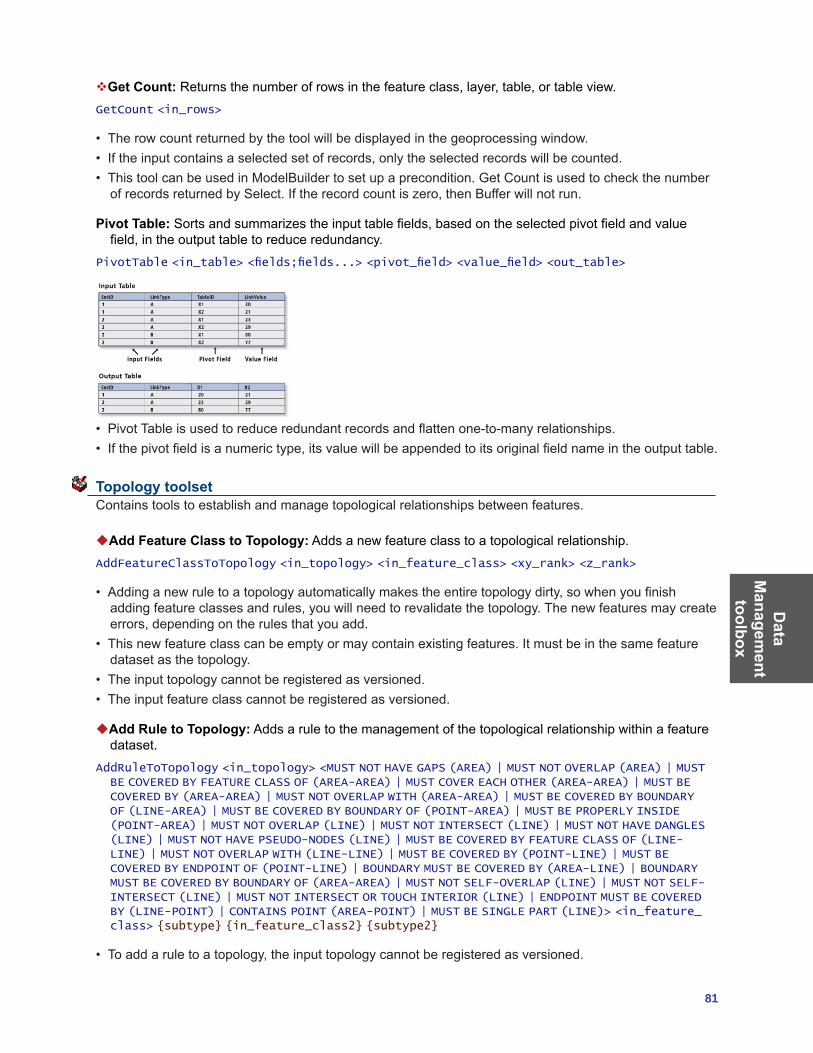
Data
Managem
ent toolbox
81
Get Count:Returnsthenumberofrowsinthefeatureclass,layer,table,ortableview.GetCount <in_rows>
• Therowcountreturnedbythetoolwillbedisplayedinthegeoprocessingwindow.• Iftheinputcontainsaselectedsetofrecords,onlytheselectedrecordswillbecounted.• ThistoolcanbeusedinModelBuildertosetupaprecondition.GetCountisusedtocheckthenumberofrecordsreturnedbySelect.Iftherecordcountiszero,thenBufferwillnotrun.
Pivot Table:Sortsandsummarizestheinputtablefields,basedontheselectedpivotfieldandvaluefield,intheoutputtabletoreduceredundancy.
PivotTable <in_table> <fields;fields...> <pivot_field> <value_field> <out_table>
• PivotTableisusedtoreduceredundantrecordsandflattenone-to-manyrelationships.• Ifthepivotfieldisanumerictype,itsvaluewillbeappendedtoitsoriginalfieldnameintheoutputtable.
Topology toolset Contains tools to establish and manage topological relationships between features.
Add Feature Class to Topology: Adds a new feature class to a topological relationship.AddFeatureClassToTopology <in_topology> <in_feature_class> <xy_rank> <z_rank>
• Addinganewruletoatopologyautomaticallymakestheentiretopologydirty,sowhenyoufinishaddingfeatureclassesandrules,youwillneedtorevalidatethetopology.Thenewfeaturesmaycreateerrors,dependingontherulesthatyouadd.
• Thisnewfeatureclasscanbeemptyormaycontainexistingfeatures.Itmustbeinthesamefeaturedataset as the topology.
• Theinputtopologycannotberegisteredasversioned.• Theinputfeatureclasscannotberegisteredasversioned.
Add Rule to Topology: Adds a rule to the management of the topological relationship within a feature dataset.
AddRuleToTopology <in_topology> <MUST NOT HAVE GAPS (AREA) | MUST NOT OVERLAP (AREA) | MUST BE COVERED BY FEATURE CLASS OF (AREA-AREA) | MUST COVER EACH OTHER (AREA-AREA) | MUST BE COVERED BY (AREA-AREA) | MUST NOT OVERLAP WITH (AREA-AREA) | MUST BE COVERED BY BOUNDARY OF (LINE-AREA) | MUST BE COVERED BY BOUNDARY OF (POINT-AREA) | MUST BE PROPERLY INSIDE (POINT-AREA) | MUST NOT OVERLAP (LINE) | MUST NOT INTERSECT (LINE) | MUST NOT HAVE DANGLES (LINE) | MUST NOT HAVE PSEUDO-NODES (LINE) | MUST BE COVERED BY FEATURE CLASS OF (LINE-LINE) | MUST NOT OVERLAP WITH (LINE-LINE) | MUST BE COVERED BY (POINT-LINE) | MUST BE COVERED BY ENDPOINT OF (POINT-LINE) | BOUNDARY MUST BE COVERED BY (AREA-LINE) | BOUNDARY MUST BE COVERED BY BOUNDARY OF (AREA-AREA) | MUST NOT SELF-OVERLAP (LINE) | MUST NOT SELF-INTERSECT (LINE) | MUST NOT INTERSECT OR TOUCH INTERIOR (LINE) | ENDPOINT MUST BE COVERED BY (LINE-POINT) | CONTAINS POINT (AREA-POINT) | MUST BE SINGLE PART (LINE)> <in_feature_class> {subtype} {in_feature_class2} {subtype2}
• Toaddaruletoatopology,theinputtopologycannotberegisteredasversioned.
Dat
a M
anag
emen
t to
olbo
x
82 ArcGIS 9: Geoprocessing Commands Quick Reference Guide
• Youcantypethenameofthesubtypevaluetowhichyouwantatopologyruletobeapplied.Ifyouareusingthecommandlineandthesubtypenameconsistsofmorethanoneword,usesinglequotestocontain the subtype name.
Create Topology: Creates a topology within a feature dataset.CreateTopology <in_dataset> <out_name> <in_cluster_tolerance>
• Thetopologyhasaminimumandmaximumclustertolerancethatisderivedfromtheprecisionofthespatial reference of the feature dataset in which you are creating the topology. If the value entered is largerthanthemaximumclustertolerance,thevaluewillbecomethemaximum.Ifthevalueenteredissmallerthantheminimum,theminimum(ordefault)willbeused.
Remove Feature Class from Topology: Removes a feature class from the topological relationship.RemoveFeatureClassFromTopology <in_topology> <in_feature_class>
• Removingafeatureclassfromatopologyalsoremovesallthetopologyrulesassociatedwiththatfeature class.
• Removingafeatureclassfromatopologywillinvalidatetheentiretopology.• Removingafeatureclassfromatopologyalterstheschemaofthetopology.Toremoveafeatureclass,
the topology must be unregistered as versioned.
Remove Rule from Topology: Removes a rule from a topological relationship.RemoveRuleFromTopology <in_topology> <in_rule>
• Whenremovingarulefromatopologyusingthecommandlineorscripting,youmustspecifythefeatureclassObjectClassIDinbracketsaftertherulename.Seethecommandlinesyntaxforanexample.IfyouareusingtheRemoveFeatureClassFromTopologytool,thelistofrulesispresentedto you in a drop-down list.
• Removingarulewillrequirethetopologytoberevalidated.• Removingatopologyrulealterstheschemaofthetopologyandrequiresanexclusivelock.Italsorequiresthatthetopologybeunregisteredasversioned.
Set Cluster Tolerance: Alters the cluster tolerance in a topological relationship.SetClusterTolerance <in_topology> <cluster_tolerance>
• Youcannotaltertheclustertoleranceforatopologyifthetopologyhasbeenregisteredasversioned.• Changingtheclustertolerancewillrequiretheentiretopologytobevalidated.
Validate Topology:Evaluatesthefeaturesagainsttherulesandfindsanynewerrorsrelatedtonewrules or feature classes.
ValidateTopology <in_topology> {FULL_EXTENT | VISIBLE_EXTENT}
• IfyouvalidateanArcSDEgeodatabasetopologyinArcCatalog,thefeaturedatasetthatthetopologyiswithin must not be registered as versioned.
• Validatewillonlyprocessareasofthetopologythatrequirevalidation.IfyouvalidatethetopologyinArcMap,youcanoptionallyusethevisibleextentastheareayouwanttovalidate.Allareasoutsidethevisible extent will not be validated.

Data
Managem
ent toolbox
83
Versions toolset Contains tools to make adjustments to the versions of the data.
Alter Version:Altersthepropertiesofanyoftheversionsofthedatasetincludingname,description,and access permissions.
AlterVersion <in_workspace> <in_version> {name} {description} {PRIVATE | PUBLIC | PROTECTED}
• Neitherpersonalnorfilegeodatabasessupportversioning.VersioningtoolsonlyworkwithArcSDEdata.
• Versionsarenotaffectedbychangesoccurringinotherversionsofthedatabase.• Aversion’spermissioncanonlybechangedbyitsowner.
Create Version:Createsanewversionofthespecifieddatabase.CreateVersion <in_workspace> <parent_version> <version_name> {PRIVATE | PUBLIC | PROTECTED}
• TheoutputversionnameisprefixedbytheArcSDEgeodatabaseusername,forexample,SDE.arctoolbox.
• Theoutputversion’spermissionsaresetasprivatebydefaultbutcanbechangedusingtheAlterVersiontool.
Delete Version:Deletesthespecifiedversionfromtheinputworkspace.DeleteVersion <in_workspace> <version_name>
• Onlytheversion’sownercanrename,delete,oraltertheversion.• Aparentversioncan’tbedeleteduntilalldependentchildversionsaredeleted.• Versionsarenotaffectedbychangesoccurringinotherversionsofthedatabase.
Post Version: Applies the current edit session to the reconciled target version during versioned geodatabase editing.
PostVersion <in_workspace> <version_name>
• Postingsynchronizestheeditversionwiththereconciledversionandsavesthedata.• Postingcan’tbeundonesinceyouareapplyingchangestoaversionthatyouarenotcurrentlyediting.• Ifthereconciledversionismodifiedbetweenreconcilingandposting,youwillbenotifiedtoreconcile
again before posting.
Reconcile Version: Reconciles a version against a parent version in its lineage.ReconcileVersion <in_workspace> <version_name> <target_name> {BY_OBJECT | BY_ATTRIBUTE} {FAVOR_TARGET_VERSION | FAVOR_EDIT_VERSION} {LOCK_AQUIRED | NO_LOCK_AQUIRED} {NO_ABORT | ABORT_CONFLICTS} {NO_POST | POST}
• Thereconcileprocessrequiresthatyouaretheonlyusercurrentlyeditingtheversionandthatyouarethe only user able to edit the version throughout the reconcile process until you save or post.
• Thereconcileprocessrequiresthatyouhavefullpermissionstoallthefeatureclassesthathavebeenmodifiedintheversionbeingedited.
Register as Versioned: Registers an ArcSDE dataset as versioned in ArcCatalog.RegisterAsVersioned <in_dataset> {NO_EDITS_TO_BASE | EDITS_TO_BASE}
• Fileandpersonalgeodatabasesdon’tsupportversioning.VersioningtoolsonlyworkwithArcSDEdata.
Dat
a M
anag
emen
t to
olbo
x
84 ArcGIS 9: Geoprocessing Commands Quick Reference Guide
• Registeringafeaturedatasetasversionedregistersallfeatureclasseswithinthefeaturedatasetasversioned.
• Versionsarenotaffectedbychangesoccurringinotherversionsofthedatabase.• Aversion’spermissioncanonlybechangedbyitsowner.• Makingafeatureclassortablemultiversionedrequiresauniqueintegerfield.ThisistypicallytheOBJECTIDfield.
Unregister as Versioned: Unregisters an ArcSDE dataset as versioned in ArcCatalog.UnregisterAsVersioned <in_dataset> {KEEP_EDIT | NO_KEEP_EDIT} {NO_COMPRESS_DEFAULT | COMPRESS_DEFAULT}
• Makingafeatureclassortablemultiversionedrequiresauniqueintegerfield.Onlytheownerofthedata may register or unregister the object as versioned.
• Versionsarenotaffectedbychangesoccurringinotherversionsofthedatabase.• Aversion’spermissioncanonlybechangedbyitsowner.• Outstandingeditswillbelostwiththeexecutionofthistoolunlessthedatabaseiscompressedfirst.
Workspace toolset Contains tools to create the storage models used with ArcGIS.
Create ArcInfo Workspace:CreatesaworkspacewithanINFOsubdirectory.CreateArcInfoWorkspace <out_folder_path> <out_name>
• Theworkspacecannotalreadyexist.
Create Feature Dataset: Creates an empty feature dataset within an existing geodatabase.CreateFeatureDataset <out_dataset_path> <out_name> {spatial_reference}
Create File GDB: Createsanewfilegeodatabase.CreateFileGDB <out_folder_path> <out_name>
• Eachdatasetcanscaleupto1TBinsize.
Create Folder: Creates a new folder.CreateFolder <out_folder_path> <out_name>
• Theoutputfoldershouldnotalreadyexist.Anerrorwillnotoccurifthefolderalreadyexists.
Create Personal GDB: Creates a new personal geodatabase.CreatePersonalGDB <out_folder_path> <out_name>
• Theoutputpersonalgeodatabasecannotalreadyexist.• Geodatabasenamesmuststartwithavalidletter.Thefirstcharactercannotbenumeric.• Apersonalgeodatabaseisusuallyonthesamenetworkastheclientapplication(forexample,ArcCatalog)andsupportsoneeditoratatime.
Geocoding toolbox
85
Geocoding toolbox Contains tools used to manage a geocoding service and run geocoding actions.
Automate Geocoding Indexes: Creates an automatically updating relationship between the reference dataandthegeocodingindex(es)ofanaddresslocator.
NOTE:ThistoolisnolongersupportedatArcGIS9.2,becauseindexesdonotneedtobeautomated.Use the Create Address Locator tool to create a new address locator.
AutomateGeocodingIndexes <in_address_locator>
Create Address Locator: Creates a new address locator.CreateAddressLocator <in_address_locator_style> <reference_data{Role}; reference_data{Role}...> <in_field_map> <out_address_locator> {config_keyword}
• Addresslocatorscanbecreatedinthesameworkspaceofthereferencedataoranyotherworkspaceyouspecified.
• Theroleofareferencedatasetdefinestherolethatitplaysasreferencedatafortheaddresslocator.The address locator styles provided with ArcGIS use the following values to describe the roles of reference datasets: • Primarytable—Definestheprimaryreferencedatasetfeatureclassforalocator,suchasastreet
centerline feature class• AlternateNametable—Definesanalternatestreetnametableiftheaddresslocatorstylesupports
it• Aliastable—Definesaplace-namealiastable
Deautomate Geocoding Indexes: Removes the automatically updating relationship between the reference data and geocoding index of an address locator.
NOTE:ThistoolisnolongersupportedatArcGIS9.2,becauseindexesdonotneedtobedeautomated.Use the Create Address Locator tool to create a new address locator.
DeautomateGeocodingIndexes <in_address_locator>
Delete Address Locator: Deletes an address locator.
NOTE:ThistoolisnolongersupportedatArcGIS9.2.UsetheDelete(DataManagement)tooltodeletean address locator.
DeleteAddressLocator <in_address_locator>
Geocode Addresses: Creates a point feature class from a table of addresses.GeocodeAddresses <in_table> <address_locator> <in_address_fields> <out_feature_class> {STATIC | DYNAMIC}
• TheinputaddresstablecanbeanyformatsupportedbyArcGIS,includingINFO,dBASE,andgeodatabase tables.
• Theoutputfeatureclasscanbeashapefileorgeodatabasefeatureclass.• Choosetocreateadynamicgeocodedfeatureclassifyouwanteditsintheinputaddresstabletobeautomaticallyreflectedintheoutputfeatureclass.Thisoptionisonlyvalidiftheinputaddresstableandoutput feature class are in the same geodatabase workspace.

Geo
codi
ng
tool
box
86 ArcGIS 9: Geoprocessing Commands Quick Reference Guide
Rebuild Address Locator: Rebuilds an address locator.RebuildAddressLocator <in_address_locator>
• Youmusthavewriteprivilegesontheaddresslocatortousethistool.• Thereferencefeatureclassandtablesmustbeavailable.Youmayneedtorepairtheaddresslocator
particularly the paths to the reference data if the data has been moved to a different location since the last time the locator was built.
• Addresslocatorscreatedbasedonaversionedgeodatabasewillberebuiltusingthesameversion.• AddresslocatorscreatedwithversionspriortoArcGIS9.2oraddresslocatorsprovidedbyany
StreetMap™ products cannot be rebuilt.
Rebuild Geocoding Indexes: Rebuilds the indexes of an address locator.
NOTE:ThistoolisnolongersupportedatArcGIS9.2,becauseaddressattributesandindexesintheaddress locator will be refreshed. Use the Rebuild Address Locator tool to rebuild an address locator.
RebuildGeocodingIndex <in_address_locator>
Rematch Addresses: Rematches addresses in a geocoded feature class.RematchAddresses <in_geocoded_feature_class> {in_where_clause}
• TheinputfeatureclasshastobeafeatureclassthatwascreatedbytheGeocodeAddressestooloraprocess where a table of addresses were geocoded.
Standardize Addresses: Standardizestheaddressinformationinatableorfeatureclass.StandardizeAddresses <in_address_data> <in_input_address_fields;in_input_address_fields...> <in_address_locator_style> <in_output_address_fields;in_output_address_fields...> <out_address_data> {STATIC | DYNAMIC}
• Ifyouareusinganaddresslocatorstylethatgeocodesaddresseswithhousenumbers(mostaddresslocatorstylesdothis),youmustincludeafieldthatcontainsanumericvaluethatrepresentsthehousenumberintheinputaddressfields.
• Ifyourinputtableorfeatureclassandoutputtableareinthesamegeodatabaseworkspace,youcanchoose to create dynamic output.
• Bydefault,theStandardizeAddressestoolwillcreatestaticoutput,unlessyouexplicitlyspecifytocreate dynamic output.

Linear R
eferencing toolbox
87
Linear Referencing toolbox Contains tools to model relative locations along linear features and associate multiple sets of attributes to portions of linear features.
Calibrate Routes: Recalculates route measures using points. CalibrateRoutes <in_route_features> <route_id_field> <in_point_features> <point_id_field> <measure_field> <out_feature_class> {DISTANCE | MEASURES} {search_radius} {BETWEEN | NO_BETWEEN} {BEFORE | NO_BEFORE} {AFTER | NO_AFTER} {IGNORE | NO_IGNORE} {KEEP | NO_KEEP} {INDEX | NO_INDEX}
• Iftheoutputroutefeatureclasswillbewrittentoageodatabase,anappropriatemdomainshouldbeset.
• Theoutputroutefeatureclasswillincludeallthefieldsfromtheinputfeatures.• Asearchradiusofinfinitycannotbespecified.
Create Routes: Creates routes from existing lines.CreateRoutes <in_line_features> <route_id_field> <out_feature_class> <LENGTH | ONE_FIELD | TWO_FIELDS> <from_measure_field> <to_measure_field> {UPPER_LEFT | LOWER_LEFT | UPPER_RIGHT | LOWER_RIGHT} {measure_factor} {measure_offset} {IGNORE | NO_IGNORE} {INDEX | NO_INDEX}
• Iftheoutputroutefeatureclasswillbewrittentoageodatabase,anappropriatemdomainshouldbeset.
• Theuniquevaluesintherouteidentifierfieldarewrittentooutputroutefeatureclass.• UseMakeFeatureLayerorMakeQueryTabletoeffectivelyreducethenumberoflinesthatwillbe
used to create routes.• Useameasurefactortoconvertbetweenroutemeasureunits.Forexample,toconvertfromfeettomiles,useafactorof0.00018939394.
Dissolve Route Events: Removes redundant information from event tables or separates event tables having more than one descriptive attribute into separate tables.
DissolveRouteEvents <in_events> <in_event_properties> <dissolve_field; dissolve_field...> <out_table> <out_event_properties> {DISSOLVE | CONCATENATE} {INDEX | NO_INDEX}
• TheoutputtablecanbeadBASEfileorageodatabasetable.• IftheinputeventsdonothaveanobjectIDfield,useMakeQueryTablepriortoDissolveRouteEventstoaddavirtualobjectIDfield.
• Anattributeindexontherouteidentifierfieldspeedsupthedynamicsegmentationprocess.Ifyouwillbeusingtheoutputroutefeatureclassfordynamicsegmentation,itisrecommendedthatyouchooseto have an attribute index created.
Locate Features Along Routes:Computestheintersectionofinputfeatures(point,line,orpolygon)and route features and writes the route and measure information to a new event table.
LocateFeaturesAlongRoutes <in_features> <in_routes> <route_id_field> <radius_or_tolerance> <out_table> <out_event_properties> {FIRST | ALL} {DISTANCE | NO_DISTANCE} {ZERO | NO_ZERO} {FIELDS | NO_FIELDS}
• TheoutputtablecanbeadBASEfileorageodatabasetable.• TheeventtypemustbePOINTwhentheinputfeaturesarepointsandmustbeLINEwhentheinput
features are lines or polygons.• UseMakeFeatureLayertoeffectivelyreducetheinputsthatwillbeprocessed.
Line
ar
Ref
eren
cing
to
olbo
x
88 ArcGIS 9: Geoprocessing Commands Quick Reference Guide
Make Route Event Layer: Creates a temporary feature layer using routes and route events.MakeRouteEventLayer <in_routes> <route_id_field> <in_table> <in_event_properties> <out_layer> {offset_field} {NO_ERROR_FIELD | ERROR_FIELD} {NO_ANGLE_FIELD | ANGLE_FIELD} {NORMAL | TANGENT} {ANGLE | COMPLEMENT} {LEFT | RIGHT} {POINT | MULTIPOINT}
• Temporarylayersarestoredinmemoryandcanbeusedasinputtoothergeoprocessingfunctionsinyour current ArcCatalog or ArcMap session.
• UseMakeFeatureLayerontheroutesand/orMakeTableViewontheeventspriortoMakeRouteEvent Layer to reduce the number of routes and events that will be processed.
Overlay Route Events: Combinestwoinputeventtablestocreateasingleoutputeventtable,usingeither a union or intersection operation.
OverlayRouteEvents <in_table> <in_event_properties> <overlay_table> <overlay_event_properties> <INTERSECT | UNION> <out_table> <out_event_properties> {ZERO | NO_ZERO} {FIELDS | NO_FIELDS} {INDEX | NO_INDEX}
• Lineonline,lineonpoint,pointonline,andpointonpointeventoverlayscanbeperformed.• Theinputandoverlayeventsshouldbebasedonthesameroutereference.
Transform Route Events: Transforms the measures of events from one route reference to another and writes them to a new event table.
TransformRouteEvents <in_table> <in_event_properties> <in_routes> <route_id_field> <target_routes> <target_route_id_field> <out_table> <out_event_properties> <cluster_tolerance> {FIELDS | NO_FIELDS}
• Transformingeventsallowsyoutousetheeventsfromoneroutereferencewithanotherroutereferencehavingdifferentrouteidentifiersand/ormeasures.
• Anywholeorpartialeventthatintersectsatargetrouteiswrittentotheneweventtable.• Theoutputeventtype(pointorline)mustmatchtheinputeventtype.• Thebestresultswillbeachievedwhenthesourceroutesandthetargetroutescloselyoverlay.Donot
use a large cluster tolerance to try and overcome discrepancies between the source and target routes because it can lead to unexpected results.
• UseMakeTableViewpriortoTransformRouteEventstoeffectivelyreducethenumberofeventsthatwill be processed.

89
Mobile
toolbox
Mobile toolbox ContainstoolstoconvertdatatoformatsoptimizedandreadyforusewithinArcGISMobileapplications.
Create Mobile Basemap:CreatesabasemapdatasetthatisoptimizedandreadyforusewithArcGISMobile applications.
CreateMobileBasemap <in_map_document> <out_folder> {in_data_frame} {extract_extent} {extract_boundary} {in_layer;in_layer...}
• TheinputArcMapmapdocumentshouldcontainreferencestoalldatalayers(operationalandbasemap)tobeusedbythemobiledevice.Operationaldatareferstodatathatwillbesynchronizedbetween a mobile device and a server; basemap data refers to data used for reference or orientation purposes only.
• Thiscommandonlysupportstheconversionofvectordata;anyrasterlayersreferencedintheinputmap document are not eligible for extraction.
• Annotationlayersarenotsupported.• Theoutputfoldermustexistpriortocommandexecution.• Onlydatafromonedataframecanbeextractedatatime.Ifthein_data_frameparameterisnotused
then layers from the active data frame will be extracted.
Generate Mobile Service Cache: Generates a mobile service cache for use with ArcGIS Mobile applications by extracting selected operational vector and basemap raster layers from a mobile data access enabled ArcGIS Server Map Service.
GenerateMobileServiceCache <map_service> <out_folder> {override_extract_extent} {in_layer;in_layer...} {in_version} {NO_ERASE | ERASE}
• OnlyArcGISServerMapServiceswhichhavebeenpublishedwithmobiledataaccesscapabilitiescanbe used by this command.
• TheselectedArcGISServerMapServiceshouldcontainreferencestoalloperationalvectorlayersandbasemaprasterlayerstobeusedbythemobiledevice.Operationaldatareferstodatathatwillbesynchronizedbetweenamobiledeviceandaserver;basemapdatareferstodatausedforreferenceororientation purposes only.
• Onlyvectorlayersbasedonenterprisegeodatabasedatasourcescanbesynchronizedbetweenthemobile device and the ArcGIS Server.
• Theoutputfoldermustexistpriortocommandexecution.• Bydefault,theextentthatisextractedisbasedonthemapservices’initialmapextent;thiscanbeoverriddenbyusingtheoverride_extract_extentparameter.

Mob
ile
tool
box
90 ArcGIS 9: Geoprocessing Commands Quick Reference Guide

Multi-
dimension
toolbox
91
Multidimension toolbox ContainstoolstomakeanetCDFrasterlayer,featurelayer,ortableview;toconverttonetCDFfromraster,feature,ortable;andtoselectadimensionofanetCDFlayerortabletodisplay.
Feature To NetCDF:ConvertsafeatureclasstoanetCDFfile.FeatureToNetCDF <in_features> <field {Variable} {Units};field {Variable} {Units}...> <out_netCDF_file> {field {Dimension} {Units};field {Dimension} {Units}...}
• Thedefaultvariablenameisthesameasthefieldnamespecifiedinthefield_to_variableparameter.• Thetypeofvariableisthesameasthetypeoffield.• Thedefaultdimensionnameisthesameasthefieldnamespecifiedinthefield_to_dimension
parameter.• Thesizeofadimensionisequaltothenumberofuniquevaluesintherespectivefield.
Make NetCDF Feature Layer:Makesanin-memoryfeaturelayerfromanetCDFfile.MakeNetCDFFeatureLayer <in_netCDF_file> <variable;variable...> <x_variable> <y_variable> <out_feature_layer> {row_dimension;row_dimension...} {z_variable} {m_variable} {dimension {Value};dimension {Value}...} {BY_VALUE | BY_INDEX}
• Thefeaturelayercanbeusedasinputtoanygeoprocessingtoolthatacceptsafeatureclassasinput.• ThetemporaryfeaturelayercanbesavedasalayerfileusingtheSaveToLayerFiletoolorsavedasanewfeatureclassusingtheCopyFeaturestool.
• Anexistingfeaturelayerwillbeoverwrittenifthesamelayernameisspecified.
Make NetCDF Raster Layer:Makesanin-memoryrasterlayerfromanetCDFfile.MakeNetCDFRasterLayer <in_netCDF_file> <variable> <x_dimension> <y_dimension> <out_raster_layer> {band_dimension} {dimension {Value};dimension {Value}...} {BY_VALUE | BY_INDEX}
• TocreateanetCDFrasterlayerfromanetCDFvariable,thespacingbetweenx-coordinatesmustbeequalandthespacingbetweeny-coordinatesmustbeequal.Ifthecoordinatesareunequallyspaced,createanetCDFfeaturelayer,theninterpolatetoraster.
• TheoutputrasterlayertypeiseitherfloatorintegerbasedonthenetCDFvariabletype.• ThefirstvariableinthenetCDFfilesuitableforcreatingarasterisselectedasthedefaultvariable.
Make NetCDF Table View:MakesatableviewfromanetCDFfile.MakeNetCDFTableView <in_netCDF_file> <variable;variable...> <out_table_view> {row_dimension;row_dimension...} {dimension {Value};dimension {Value}...} {BY_VALUE | BY_INDEX}
• TableviewsaretablesstoredinmemoryandarethesameasthetableviewwhenatableisaddedtoArcMap.
• ArcCatalogdoesnotdisplaythesetableviews,buttheycanbeusedasinputstoothergeoprocessingtoolsinthecurrentArcGISsession.OnceArcGISexists,thetablesinmemoryareremoved.
• TableviewscreatedinArcCatalogcannotbeusedinArcMap.• Anexistingtableviewwillbeoverwrittenifthesametableviewnameisentered.
Mul
ti-di
men
sion
to
olbo
x
92 ArcGIS 9: Geoprocessing Commands Quick Reference Guide
Raster to NetCDF:ConvertsarasterdatasettoanetCDFfile.RasterToNetCDF <in_raster> <out_netCDF_file> {variable} {variable_units} {x_dimension} {y_dimension} {band_dimension} {field {Dimension} {Units};field {Dimension} {Units}...}
• Theinputcanbeanyvalidrasterdatasetorrastercatalog.• Thedefaultvariablenameisthesameastheinputrastername.• TheoutputnetCDFvariabletypeiseitherfloatorintegerbasedontheinputrasterdatasettype.
Select by Dimension:UpdatesthenetCDFlayerdisplayornetCDFtableviewbasedonthedimensionvalue.
SelectByDimension <in_layer_or_table> {dimension {Value};dimension {Value}...} {BY_VALUE | BY_INDEX}
• InputsforthistoolcanbecreatedbyusingtheMakeNetCDFFeatureLayer,MakeNetCDFRasterLayer,orMakeNetCDFTableViewtools.
• Ifadimensionisnotspecified,itsvalueissettothefirstvalue.Thefirstvalueisconsideredasthedefault value.
• Thistoolupdatestheinput.InModelBuilder,anoutputvariableappearstochaintheupdatedinputasinputtoanothertoolinthemodel,butthetooldoesnotproduceanewoutput.
Table to NetCDF:ConvertsatabletoanetCDFfile.TableToNetCDF <in_table> <field {Variable} {Units};field {Variable} {Units}...> <out_netCDF_file> {field {Dimension} {Units};field {Dimension} {Units}...}
• Thedefaultvariablenameisthesameasthefieldnamespecifiedinthefield_to_variableparameter.• Thetypeofthevariableisthesameasthetypeofthefield.

Servertoolbox
93
Server toolbox Containsstatisticaltoolsforanalyzingthedistributionofgeographicfeatures.
Caching toolset
Create Map Server Cache:Createsthecachetilingschemeforagivenmapservice.Oncethetilingscheme is created use the Manage Map Server Cache Tiles tool to generate tiles for your cache.
CreateMapServerCache <server_name> <object_name> <data_frame> <out_folder> <NEW | PREDEFINED> <STANDARD | CUSTOM> <number_of_scales> <dpi> <tile_width> <tile_height> {FUSED | MULTI_LAYER} {tiling_schema} {tile_origin} {Scale;Scale...} {Layer;Layer...} {NONE | ANTIALIASING} {PNG8 | PNG24 | PNG32 | JPEG} {tile_compression_quality}
• ThistoolonlyworkswithArcGISServermapservices.• Onlyonedataframecanbecachedatatime.Ifotherdataframesareneeded,separatecachesmust
be generated that associated with separate map services.• Onceyoucreatethetilingschemeyoucannotmodifyit.Youcanhoweveraddordeletescalestoan
existing tiling scheme using the Manage Map Server Cache Scales tool. • TheNumberofScalesparameteristhenumberofdifferentmapscalesthetoolwillcreatelayersforin
the cache. • JPEGisbestusedwithrasterdata.Whenusedwithvectordata,linesandtextmaybeblurred.• Thecachetileformatcannotbechangedoncethecacheisgenerated.Thecachemustfirstbedeletedbeforeswitchingtoadifferentfileformat.
Delete Globe Server Cache:Deletesanexistingglobeservicelayer’scache.DeleteGlobeServerCache <server_name> <object_name> <Layer;Layer...>
• Thisisanunrecoverableoperationsoonlyuseifyouaresureyounolongerneedthecache.• Bydefaultalllayersoftheservicearedisplayedandselected.Ifyouintendtodeleteonlyaparticularlayerscache,makesuretounselecttheonesyouwanttokeepthecachefor.
• DeleteGlobeServerCachetoolcanbehelpfulifyouhavemanycachesresidinginyourservercachedirectory and want to delete only a particular services cache.
• DeleteGlobeServerCachedeletestheentirecachefolder.NotethatafterDeleteGlobeServerCachetool runs it will restart the server object. This will in turn generate a new set of caches for each layer in theservicethatwasdeletedbythedeleteoperation.Thisisbecauseallglobeserviceswillrequireacacheconfigurationtoexistondisktorun.Thecachethatgetscreatedautomaticallyonstartupofaservice is a skeleton representation that does not contain any tiles.
Delete Map Server Cache:Deletesanexistingmapservicecacheincludingallassociatedfilesondisk.
DeleteMapServerCache <server_name> <object_name> <data_frame> <Layer;Layer...>
• Thisisanunrecoverableoperationsoonlyuseifyouaresureyounolongerneedthecache• Ifthereismorethanonedataframeinthecachedirectoryonlytheactivedataframeofthespecified
map service will be removed.• Ifthereisonlyonedataframeinthecachedirectorytheentiredirectorywillberemoved.• Afterthistoolrunsthemapservicewillberestarted.

Serv
erto
olbo
x
94 ArcGIS 9: Geoprocessing Commands Quick Reference Guide
Generate Globe Server Cache: Generates globe data caches based on the ArcGlobe data tiling scheme.
NOTE:ThistoolishasbeendeprecatedinArcGIS9.3andreplacedwiththeManageGlobeServerCacheTiles tool.
GenerateGlobeServerCache <server_name> <object_name> <out_folder> <GLOBE - 1:10000000 | CONTINENT - 1:5000000 | COUNTRIES - 1:2500000 | COUNTRY - 1:1250000 | STATES - 1:625000 | STATE - 1:312500 | COUNTIES - 1:156250 | COUNTY - 1:78125 | METROPOLITAN AREA - 1:39062 | CITIES - 1:19531 | CITY - 1:9765 | TOWN - 1:4882 | NEIGHBORHOOD - 1:2441 | CITY BLOCKS - 1:1220 | CITY BLOCK - 1:610 | BUILDINGS - 1:305 | BUILDING - 1:152 | HOUSES - 1:76 | HOUSE PROPERTY - 1:38 | HOUSE - 1:19 | ROOMS - 1:9 | ROOM - 1:4> <ROOM - 1:4 | ROOMS - 1:9 | HOUSE - 1:19 | HOUSE PROPERTY - 1:38 | HOUSES - 1:76 | BUILDING - 1:152 | BUILDINGS - 1:305 | CITY BLOCK - 1:610 | CITY BLOCKS - 1:1220 | NEIGHBORHOOD - 1:2441 | TOWN - 1:4882 | CITY - 1:9765 | CITIES - 1:19531 | METROPOLITAN AREA - 1:39062 | COUNTY - 1:78125 | COUNTIES - 1:156250 | STATE - 1:312500 | STATES - 1:625000 | COUNTRY - 1:1250000 | COUNTRIES - 1:2500000 | CONTINENT - 1:5000000 | GLOBE - 1:10000000> {thread_count} <Layer;Layer...>
Generate Map Server Cache: Generates a cache of static image tiles for an ArcGIS Server map service.
NOTE:ThistoolishasbeendeprecatedinArcGIS9.3andreplacedwiththeCreateMapServerCachetool,followed by the Manage Map Server Cache Tiles tool.
GenerateMapServerCache <server_name> <object_name> <data_frame> <out_folder> <NEW | PREDEFINED> <STANDARD| CUSTOM> <num_of_scales> <dpi> <tile_width> <tile_height> {FUSED| MULTI_LAYER} {tiling_schema} {tile_origin} {Scale; Scale...} {Layer; Layer...} {thread_count} {ANTIALIASING | NONE} {PNG8 | PNG24 | PNG32 | JPEG} {tile_compression_quality}
Generate Map Server Cache Tiling Scheme:Generatesatilingschemexmlfileforusewhencreatingastatic map service cache.
GenerateMapServerCacheTilingScheme <map_document> <data_frame> <tile_origin> <tiling_schema> <cache_levels> <Scale;Scale...> <dpi> <tile_width> <tile_height>
• Bydefault,thetilingoriginstartsattheupperleftofthecoordinatereferencesystemofthedatasource.• Onceacachehasbeencreatedwithatilingschemeitcannotuseadifferenttilingschemeinthefuture(whileupdating,forexample).
Manage Globe Server Cache Tiles:Updatesanexistingglobeservicecachetoreplacemissingtiles,overwriteoutdatedtiles,oraddnewtilesinnewareas.
ManageGlobeServerCacheTiles <server_name> <object_name> <layer {level_from} {level_to};layer {level_from} {level_to}...> <RECREATE EMPTY TILES | RECREATE ALL TILES> {update_extent} {thread_count} {update_feature_class} {IGNORE_COMPLETION_STATUS_FIELD | TRACK_COMPLETION_STATUS}
• Runningupdatewithoutspecifyinganextentwillupdatetheentireextentoftheservicebeingforthespecifiedlevelsofdetail.
• Updateisusefultorunwhenyouneedtoupdateonlyaportionoftheglobeservicescache.Whenspecifyingthefromandtolevelsofdetail,makesureyouspecifyalllevelsyouwanttilesgeneratedfor.Thelevel_fromdefinesthelowestlevelofdetailyou’dwantyourdatacachetobeginwith.Thelevel_todefinesthehighestresolutionyou’dwantyourdatacachingtohave.
Manage Map Server Cache Scales: Update map server cache scales on an existing cached map service. ManageMapServerCacheScales <server_name> <object_name> <Scale;Scale...>
• Use this tool to add new scales or delete existing scales from a map cache.• Onceyoudefineatilingschemaforamapcacheyoucannotaddnewscalestoit.Usethistooltoinsert
new cache scales or remove existing cache scales.• Ifyouremovescalesfromanexistingcache,itwillpermanentlydeleteallexistingcachedtileswithinthat
level of detail.

Servertoolbox
95
Manage Map Server Cache Tiles:Createsnewtilesorreplacesmissingtiles,overwritesoutdatedtiles,oraddsnewtilesinnewareasbyspecificextentsorusingapolygonfeatureclasstogeneratetilesbyfeatureextents,or,inthecaseofamulti-layercache,fromadditionallayers.
ManageMapServerCacheTiles <server_name> <object_name> <data_frame> <Layer;Layer...> <Levels;Levels...> <RECREATE EMPTY TILES | RECREATE ALL TILES | DELETE TILES> {constraining_extent} {thread_count} {NONE | ANTIALIASING} {update_feature_class} {IGNORE_COMPLETION_STATUS_FIELD | TRACK_COMPLETION_STATUS}
• UseRecreateEmptyTilesmodetoaddtilesinanextentnotpreviouslycached.• UseRecreateAllTilestoupdateoutdatedtiles.• Beforerunningthistool,configurethemapservicetouseasmanyinstancesaspossible.Thiswill
dramatically decrease cache update time.
Update Globe Server Cache:Updatesanexistingglobeservicecachetoreplacemissingtiles,overwriteoutdatedtiles,oraddnewtilesinnewareas.
NOTE:ThistoolishasbeendeprecatedinArcGIS9.3andreplacedwiththeManageGlobeServerCacheTiles tool.
UpdateGlobeServerCache <server_name> <object_name> {update_extent} <layer;layer...> <LOD_from> <LOD_to> {thread_count} <Recreate Empty Tiles | Recreate All Tiles>
Update Map Server Cache:Updatesanexistingmapservicecachetoreplacemissingtiles,overwriteoutdatedtiles,oraddnewtilesinnewareasor,inthecaseofamulti-layercache,fromadditionallayers.
NOTE:ThistoolishasbeendeprecatedinArcGIS9.3andreplacedwiththeManageMapServerCacheTilestool.
UpdateMapServerCache <server_name> <object_name> <data_frame> <layer;layer...> {constraining_extent} <scale;scale...> <RECREATE_EMPTY_TILES| RECREATE_ALL_TILES> {thread_count} {NONE | ANTIALIASING} {update_feature_class} {CACHE ALL FEATURES AND IGNORE COMPLETION STATUS FIELD | TRACK CACHE COMPLETION STATUS FOR EACH FEATURE}

Serv
erto
olbo
x
96 ArcGIS 9: Geoprocessing Commands Quick Reference Guide

Spatial
Statisticstoolbox
97
Spatial Statistics toolbox Containsstatisticaltoolsforanalyzingthedistributionofgeographicfeatures.
Analyzing Patterns toolset Containstoolstocalculatestatisticalvaluesusedtoquantifypattern.
Average Nearest Neighbor: Calculates a nearest neighbor index based on the average distance from each feature to its nearest neighboring feature.
AverageNearestNeighbor <input_feature_class> <EUCLIDEAN DISTANCE | MANHATTAN DISTANCE> {FALSE | TRUE} {area}
• Thenearestneighborindexisexpressedastheratiooftheobserveddistancedividedbytheexpecteddistance(hypotheticalrandomdistribution).Hence,iftheindexislessthan1,thepatternexhibitsclustering;iftheindexisgreaterthan1,thetrendistowarddispersionorcompetition.
• Ifanareavalueisnotspecified,thenavaluecalculatedfromthemapextentisused[area=(xmax-xmin)*(ymax-ymin)].Thenearestneighborfunction,however,issensitivetotheareavalue(smallchangesintheareacanresultinsignificantchangesintheresults).Togetbetterresults,anaccuratevalue for area should be used.
High/Low Clustering (Getis-Ord General G): Measures the degree of clustering for either high values or low values.
HighLowClustering <input_feature_class> <input_field> {FALSE | TRUE} <INVERSE DISTANCE | INVERSE DISTANCE SQUARED | FIXED DISTANCE BAND | ZONE OF INDIFFERENCE |POLYGON CONTIGUITY (FIRST ORDER) | GET SPATIAL WEIGHTS FROM FILE> <EUCLIDEAN DISTANCE | MANHATTAN DISTANCE> <NONE | ROW> <distance_band_or_threshold_distance> {weights_matrix_file}
• AhighGeneralGvalueindicatesthathighvaluesareclusteredwithinthestudyarea;alowGeneralGvalue indicates that low values tend to cluster.
• Althoughthistoolwillworkwithpolygonorlinedata,itisreallyonlyappropriateforevent,incident,orotherfixed-pointfeaturedata.
• Forlineandpolygonfeatures,geometriccentroidsarecalculatedbeforethecentralfeatureisidentified.Thegeometriccentroidofafeaturemaybelocatedoutsideafeature’sboundary.Ifcentroidsmustbewithinfeatureboundaries,usetheFeaturestoPointtool(Insideoption)tocreatecentroidsbeforeperforming the nearest neighbor operation.
Multi-Distance Spatial Cluster Analysis (Ripley’s K-function): Determines whether a feature class is clustered at multiple different distances. The tool outputs the result as a table and optionally as a pop-up graphic.
MultiDistanceSpatialClustering <input_feature_class> <output_table> <EUCLIDEAN DISTANCE | MANHATTAN DISTANCE> <number_of_distance_bands> {0 PERMUTATIONS - NO CONFIDENCE ENVELOPE | 9 PERMUTATIONS | 99 PERMUTATIONS | 999 PERMUTATIONS} {FALSE | TRUE} {weight_field} {beginning_distance} {distance_increment} {NONE | SIMULATE OUTER BOUNDARY VALUES | REDUCE ANALYSIS AREA | RIPLEY’S EDGE CORRECTION FORMULA} {MINIMUM ENCLOSING RECTANGLE | USER PROVIDED STUDY AREA FEATURE CLASS} {study_area_feature_class}
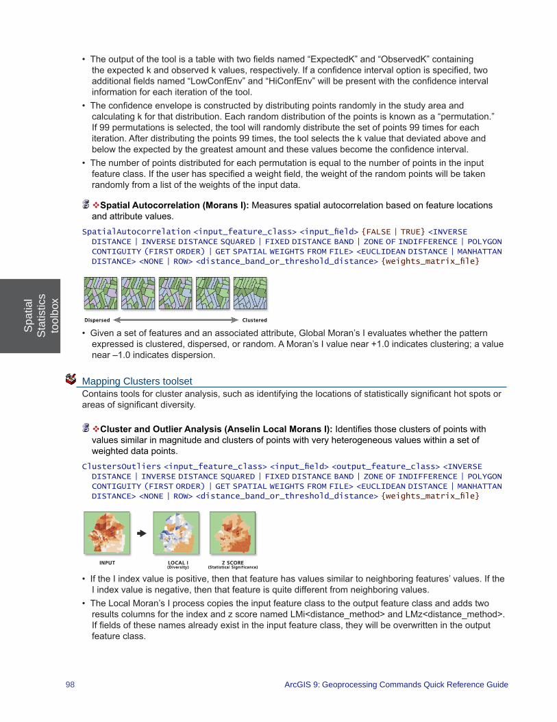
Spa
tial
Sta
tistic
sto
olbo
x
98 ArcGIS 9: Geoprocessing Commands Quick Reference Guide
• Theoutputofthetoolisatablewithtwofieldsnamed“ExpectedK”and“ObservedK”containingtheexpectedkandobservedkvalues,respectively.Ifaconfidenceintervaloptionisspecified,twoadditionalfieldsnamed“LowConfEnv”and“HiConfEnv”willbepresentwiththeconfidenceintervalinformation for each iteration of the tool.
• Theconfidenceenvelopeisconstructedbydistributingpointsrandomlyinthestudyareaandcalculatingkforthatdistribution.Eachrandomdistributionofthepointsisknownasa“permutation.”If99permutationsisselected,thetoolwillrandomlydistributethesetofpoints99timesforeachiteration.Afterdistributingthepoints99times,thetoolselectsthekvaluethatdeviatedaboveandbelowtheexpectedbythegreatestamountandthesevaluesbecometheconfidenceinterval.
• Thenumberofpointsdistributedforeachpermutationisequaltothenumberofpointsintheinputfeatureclass.Iftheuserhasspecifiedaweightfield,theweightoftherandompointswillbetakenrandomly from a list of the weights of the input data.
Spatial Autocorrelation (Morans I): Measures spatial autocorrelation based on feature locations and attribute values.
SpatialAutocorrelation <input_feature_class> <input_field> {FALSE | TRUE} <INVERSE DISTANCE | INVERSE DISTANCE SQUARED | FIXED DISTANCE BAND | ZONE OF INDIFFERENCE | POLYGON CONTIGUITY (FIRST ORDER) | GET SPATIAL WEIGHTS FROM FILE> <EUCLIDEAN DISTANCE | MANHATTAN DISTANCE> <NONE | ROW> <distance_band_or_threshold_distance> {weights_matrix_file}
• Givenasetoffeaturesandanassociatedattribute,GlobalMoran’sIevaluateswhetherthepatternexpressedisclustered,dispersed,orrandom.AMoran’sIvaluenear+1.0indicatesclustering;avaluenear –1.0 indicates dispersion.
Mapping Clusters toolset Containstoolsforclusteranalysis,suchasidentifyingthelocationsofstatisticallysignificanthotspotsorareasofsignificantdiversity.
Cluster and Outlier Analysis (Anselin Local Morans I):Identifiesthoseclustersofpointswithvalues similar in magnitude and clusters of points with very heterogeneous values within a set of weighted data points.
ClustersOutliers <input_feature_class> <input_field> <output_feature_class> <INVERSE DISTANCE | INVERSE DISTANCE SQUARED | FIXED DISTANCE BAND | ZONE OF INDIFFERENCE | POLYGON CONTIGUITY (FIRST ORDER) | GET SPATIAL WEIGHTS FROM FILE> <EUCLIDEAN DISTANCE | MANHATTAN DISTANCE> <NONE | ROW> <distance_band_or_threshold_distance> {weights_matrix_file}
• IftheIindexvalueispositive,thenthatfeaturehasvaluessimilartoneighboringfeatures’values.IftheIindexvalueisnegative,thenthatfeatureisquitedifferentfromneighboringvalues.
• TheLocalMoran’sIprocesscopiestheinputfeatureclasstotheoutputfeatureclassandaddstworesultscolumnsfortheindexandzscorenamedLMi<distance_method>andLMz<distance_method>.Iffieldsofthesenamesalreadyexistintheinputfeatureclass,theywillbeoverwrittenintheoutputfeature class.
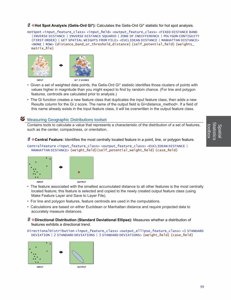
Spatial
Statisticstoolbox
99
Hot Spot Analysis (Getis-Ord Gi*):CalculatestheGetis-OrdGi*statisticforhotspotanalysis.HotSpot <input_feature_class> <input_field> <output_feature_class> <FIXED DISTANCE BAND |INVERSE DISTANCE | INVERSE DISTANCE SQUARED | ZONE OF INDIFFERENCE | POLYGON CONTIGUITY (FIRST ORDER) | GET SPATIAL WEIGHTS FROM FILE> <EUCLIDEAN DISTANCE | MANHATTAN DISTANCE> <NONE | ROW> {distance_band_or_threshold_distance} {self_potential_field} {weights_matrix_file}
• Givenasetofweighteddatapoints,theGetis-OrdGi*statisticidentifiesthoseclustersofpointswithvalueshigherinmagnitudethanyoumightexpecttofindbyrandomchance.(Forlineandpolygonfeatures,centroidsarecalculatedpriortoanalysis.)
• TheGifunctioncreatesanewfeatureclassthatduplicatestheinputfeatureclass,thenaddsanewResultscolumnfortheGizscore.ThenameoftheoutputfieldisGi<distance_method>.Ifafieldofthisnamealreadyexistsintheinputfeatureclass,itwillbeoverwrittenintheoutputfeatureclass.
Measuring Geographic Distributions toolset Containstoolstocalculateavaluethatrepresentsacharacteristicofthedistributionofasetoffeatures,suchasthecenter,compactness,ororientation.
Central Feature: Identifiesthemostcentrallylocatedfeatureinapoint,line,orpolygonfeature.CentralFeature <input_feature_class> <output_feature_class> <EUCLIDEAN DISTANCE | MANHATTAN DISTANCE> {weight_field}{self_potential_weight_field} {case_field}
• Thefeatureassociatedwiththesmallestaccumulateddistancetoallotherfeaturesisthemostcentrallylocatedfeature;thisfeatureisselectedandcopiedtothenewlycreatedoutputfeatureclass(usingMakeFeatureLayerandSavetoLayerFile).
• Forlineandpolygonfeatures,featurecentroidsareusedinthecomputations.• CalculationsarebasedoneitherEuclideanorManhattandistanceandrequireprojecteddatato
accurately measure distances.
Directional Distribution (Standard Deviational Ellipse): Measures whether a distribution of features exhibits a directional trend.
DirectionalDistribution <input_feature_class> <output_ellipse_feature_class> <1 STANDARD DEVIATION | 2 STANDARD DEVIATIONS | 3 STANDARD DEVIATIONS> {weight_field} {case_field}
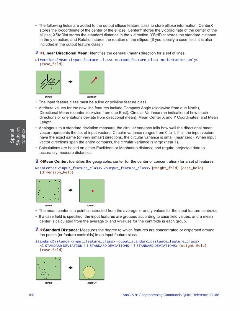
Spa
tial
Sta
tistic
sto
olbo
x
100 ArcGIS 9: Geoprocessing Commands Quick Reference Guide
• Thefollowingfieldsareaddedtotheoutputellipsefeatureclasstostoreellipseinformation:CenterXstoresthex-coordinateofthecenteroftheellipse,CenterYstoresthey-coordinateofthecenteroftheellipse,XStdDiststoresthestandarddistanceinthexdirection,YStdDiststoresthestandarddistanceintheydirection,andRotationstorestherotationoftheellipse.(Ifyouspecifyacasefield,itisalsoincludedintheoutputfeatureclass.)
Linear Directional Mean:Identifiesthegeneral(mean)directionforasetoflines.DirectionalMean <input_feature_class> <output_feature_clas> <orientation_only> {case_field}
• Theinputfeatureclassmustbealineorpolylinefeatureclass.• AttributevaluesforthenewlinefeaturesincludeCompassAngle(clockwisefromdueNorth),DirectionalMean(counterclockwisefromdueEast),CircularVariance(anindicationofhowmuchdirectionsororientationsdeviatefromdirectionalmean),MeanCenterXandYCoordinates,andMeanLength.
• Analogoustoastandarddeviationmeasure,thecircularvariancetellshowwellthedirectionalmeanvector represents the set of input vectors. Circular variance ranges from 0 to 1. If all the input vectors havetheexactsame(orverysimilar)directions,thecircularvarianceissmall(nearzero).Wheninputvectordirectionsspantheentirecompass,thecircularvarianceislarge(near1).
• CalculationsarebasedoneitherEuclideanorManhattandistanceandrequireprojecteddatatoaccurately measure distances.
Mean Center:Identifiesthegeographiccenter(orthecenterofconcentration)forasetoffeatures.MeanCenter <input_feature_class> <output_feature_class> {weight_feld} {case_field} {dimension_field}
• Themeancenterisapointconstructedfromtheaveragex-andy-valuesfortheinputfeaturecentroids.• Ifacasefieldisspecified,theinputfeaturesaregroupedaccordingtocasefieldvalues,andamean
center is calculated from the average x- and y-values for the centroids in each group.
Standard Distance: Measures the degree to which features are concentrated or dispersed around thepoints(orfeaturecentroids)inaninputfeatureclass.
StandardDistance <input_feature_class> <ouput_standard_distance_feature_class> <1 STANDARD DEVIATION | 2 STANDARD DEVIATIONS | 3 STANDARD DEVIATIONS> {weight_field} {case_field}

Spatial
Statisticstoolbox
101
• Thestandarddistancecalculationmaybebasedonanoptionalweight(togetthestandarddistanceofbusinessesweightedbyemployees,forexample).
• Thestandarddistanceisausefulstatistic,asitprovidesasinglesummarymeasureoffeaturedistributionaroundanygivenpoint(similartothewayastandarddeviationmeasuresthedistributionofdatavaluesaroundthestatisticalmean).
• StandardDistancecreatesanewfeatureclasscontainingacirclepolygoncenteredoneachofthecentralfeatures(meancenters).Eachcirclepolygonisdrawnwitharadiusequaltothestandarddistance. The attribute value for each circle polygon is its standard distance.
• Iftheunderlyingpatterninthedataistrulyrandom,theonestandarddeviationpolygonwillcoverapproximately68percentofthefeaturesinthecluster.Twostandarddeviationswillcontainapproximately95percentofthefeatures,andthreestandarddeviationswillcoverapproximately99percent of the features in the cluster.
• Ameancentercalculationisusedtodeterminethegeographiccentersoftheinputfeatureclass.
Modeling Spatial Relationships toolset Contains tools to construct spatial weights matrices or model spatial relationships using regression analyses.
Generate Network Spatial Weights:Constructsaspatialweightsmatrixfile(.swm)fromanetworkdataset;whichdefinesspatialrelationshipsamongallfeaturesintermsofanunderlyingnetworkstructure.RequiresaNetworkAnalystlicense.
GenerateNetworkSpatialWeights <input_feature_class> <unique_ID_field> <output_spatial_weights_matrix_file> <input_network> <impedance_attribute> {impedance_cutoff} {maximum_number_of_neighbors} {barriers} {ALLOW_UTURNS | NO_UTURNS | ALLOW_DEAD_ENDS_ONLY} {Restrictions;Restrictions...} {NO_HIERARCHY | USE_HIERARCHY} {search_tolerance} {INVERSE | FIXED} {exponent} {ROW_STANDARDIZATION | NO_STANDARDIZATION}
• Thistoolwasdesignedtoworkwithpointinputfeatureclassdataonly.
Generate Spatial Weights Matrix:Constructsaspatialweightsmatrix(.swm)filetorepresentthespatial relationships among features in a dataset.
GenerateSpatialWeightsMatrix <input_feature_class> <unique_ID_field> <output_spatial_weights_matrix_file> <INVERSE_DISTANCE | FIXED_DISTANCE | K_NEAREST_NEIGHBORS | CONTIGUITY_EDGES_ONLY | CONTIGUITY_EDGES_CORNERS | DELAUNAY_TRIANGULATION | CONVERT_TABLE> {EUCLIDEAN | MANHATTAN} {exponent} {threshold_distance} {number_of_neighbors} {ROW_STANDARDIZATION | NO_STANDARDIZATION } {input_table}
• Thistoolhonorstheenvironmentoutputcoordinatesystem.Featuregeometryisprojectedtotheoutputcoordinatesystempriortoanalysis,sovaluesenteredfortheThresholdDistanceparameterusethesameunitsasthosespecifiedintheoutputcoordinatesystem.Allmathematicalcomputationsarebasedontheoutputcoordinatesystem.Consequently,iftheoutputcoordinatesystemdoesnotmatchtheinputfeatureclassspatialreference,eithermakesure,forallanalysesusingthespatialweightsmatrixfile,thattheoutputcoordinatesystemmatchesthesettingsusedwhenthespatialweightsmatrixfilewascreated.
• Wheneverusingadistance-basedConceptualizationofSpatialRelationships,youshouldprojectyourdatausingaProjectedCoordinateSystem(ratherthanaGeographicCoordinateSystembasedondegrees,minutes,andseconds)priortoanalysis.Toavoidconfusion,thisprojectionshouldmatchtheenvironment output coordinate system settings.
• Theunique_ID_fieldisusedtorelatefeaturestooneanother(therelationshiporweightbetweenfeatures1and5,forexample).Consequently,theunique_ID_fieldvaluesmustbeuniqueforeveryfeatureandtypicallyshouldbeapermanentfieldthatwillremainwiththefeatureclass.

Spa
tial
Sta
tistic
sto
olbo
x
102 ArcGIS 9: Geoprocessing Commands Quick Reference Guide
Geographicaly Weighted Regression (GWR):Performsalocalformoflinearregressionusedtomodel spatially varying relationships.
GeographicalyWeightedRegression <in_features> <dependent_field> <explanatory_field> <out_feature_class> <FIXED | ADAPTIVE> <AICc | CV | BANDWIDTH PARAMETER> {distance} {number_of_neighbors} {weight_field} {coefficient_raster_workspace} {cell_size} {in_prediction_locations> {Prediction_explanatory_field;Prediction_explanatory_field...} {out_prediction_feature_class}
• Inglobalregressionmodels,suchasOrdinaryLeastSquares(OLS),resultsareunreliablewhentwoormorevariablesexhibitmulticollinearity(whentwoormorevariablesareredundantortogethertellthesame“story”).GWRbuildsalocalregressionequationforeachfeatureinthedataset.Whenthevaluesforaparticularexplanatoryvariableclusterspatially,youwillverylikelyhaveproblemswithlocalmulticolliearity.Theconditionnumberintheout_feature_classindicateswhenresultsareunstableduetolocalmulticollinearity.Asaruleofthumb,donottrustresultsforfeatureswithaconditionnumberlarger than 30.
• CautionshouldbeusedwhenincludingnominalorcategoricaldatainaGWRmodel.Wherecategoriesclusterspatially,thereisstrongriskofencounteringlocalcollinearityissues.TheconditionnumberincludedintheGWRoutputindicateswhenlocalcollinearityisaproblem.Resultsinthepresenceoflocal collinearity are unstable.
• GWRshouldbeappliedtodatasetswithseveralhundredfeaturesforbestresults.Itisnotanappropriate method for small datasets.
• Aregressionmodelismisspecifiedifitismissingakeyexplanatoryvariable.Statisticallysignificantspatial autocorrelation of the regression residuals and or unexpected spatial variation among the coefficientsofoneormoreexplanatoryvariablessuggeststhatyourmodelismisspecified.Youshouldmakeeveryeffort(throughOLSresidualanalysisandGWRcoefficientvariationanalysis)todiscoverwhat these key missing variables are so they may be included in the model.
Ordinary Least Squares:PerformsglobalOrdinaryLeastSquareslinearregressiontogeneratepredictions or to model a dependent variable in terms of a its relationships to a set of explanatory variables.RequiresanArcInfoorSpatialAnalystlicense.
OrdinaryLeastSquares <input_feature_class> <unique_ID_field> <output_feature_class> <dependent_variable> <Explanatory_variables;Explanatory_variables ...> {coefficient_output_table} {diagnostic_output_table}
• Theunique_IDfieldisusedtolinkoutputresultstoinputfeatures.Consequently,theunique_IDfieldvaluesmustbeuniqueforeveryfeatureandtypicallyshouldbeapermanentfieldthatwillremainwiththe feature class.
• TheOLSmodelismisspecified,andconsequentlyresultsfromOLSregressionareunreliable,wheneverthereisstatisticallysignificantspatialautocorrelationoftheregressionresiduals.Besureto run the Spatial Autocorrelation tool on your regression residuals to assess this potential problem. Statisticallysignificantspatialautocorrelationofregressionresidualsusuallyindicatesakeymissingexplanatory variable.
• Whenmisspecificationistheresultoftryingtomodelnon-stationaryvariablesusingaglobalmodel(OLSisaglobalmodel),thenGeographicallyWeightedRegressionmaybeusedtoimprovepredictionsandtobetterunderstandthenon-stationarity(regionalvariation)inherentinyourexplanatoryvariables.
• Youshouldvisuallyinspecttheoverandunderpredictionsevidentinyourregressionresidualstoseeif they provide clues about potential missing variables from your regression model. It sometimes helps torunHotSpotAnalysisontheresidualstohelpyouvisualizespatialclusteringoftheoverandunderpredictions.

Spatial
Statisticstoolbox
103
Rendering toolset Containstoolstoperformavarietyofdatarenderingtasksbutarebeingphasedout.Witheachtooldescriptionwillbetherecommendedtool(ifitexists)toreplacethecurrentrenderingtool.
Cluster/Outlier Analysis with Rendering: Identifiesclustersofpointswithvaluessimilarinmagnitude and clusters of points with very heterogeneous values within a given set of weighted data pointsandappliesa“coldtohot”typeofrendering.ReplacewithClusterandOutlierAnalysis(AnselinLocalMoransI);renderingisnowautomatic.
ClustersOutliersRendered <input_feature_class> <input_field> <output_layer_file> <output_feature_class>
Collect Events with Rendering: Converts event data to weighted point data and applies a graduatedcirclerenderingtothecountfield.ReplacewithCollectEvents;renderingisnowautomatic.
CollectEventsRendered <input_incident_features> <output_layer_file> <output_weighted_point_feature_class>
Count Rendering:Appliesgraduatedcirclerenderingtoacounttypefieldofapointfeatureclass.CountRenderer <input_feature_class> <field_to_render> <output_layer_file> <number_of_classes> <MANGO | BRIGHT_RED | DARK_GREEN | GREEN | DARK_BLUE | BRIGHT_PINK | LIGHT_YELLOW| SKY_BLUE> {maximum_field_value}
• TheCountRendererdrawsquantitiesusingcirclesizetoshowrelativevalues.
Hot Spot Analysis with Rendering:CalculatesGi*statisticsandappliesacoldtohottypeofrenderingtotheoutputZscores.ReplacewithHotSpotAnalysis(Getis-OrdGi*);renderingisnowautomatic.
HotSpotsRendered <input_feature_class> <input_field> <output_layer_file> <output_feature_class> <distance_band_or_threshold_distance>

Spa
tial
Sta
tistic
sto
olbo
x
104 ArcGIS 9: Geoprocessing Commands Quick Reference Guide
Z Score Rendering:Appliesacoldorhotgraduatedcolorrenderingtoafieldofzscores.ZRenderer <input_feature_class> <field_to_render> <output_layer_file>
• ThistoolisappropriateforrenderingoutputfrombothHotSpotAnalysisandDiversityAnalysis.
Utilities toolset Contains tools to perform a variety of data conversion tasks.
Calculate Areas: Calculates area values for each feature in a polygon feature class.CalculateAreas <input_feature_class> <output_feature_class>
• Thistoolisusefulindeterminingaweightforintrazonalinteraction.• ThefieldF_AREAiscreatedintheoutputfeatureclasstostorecalculatedAreavalues.Ifafieldofthisnamealreadyexistsintheinputfeatureclass,itwillbeoverwrittenintheoutputfeatureclass.
Calculate Distance Band from Neighbor Count: Calculates the distance for all features in the input featureclasstotheirnthneighbor(specifiedintheNeighborsparameter)andexaminesthedistancesandreturnsthreevalues:themaximumdistance,theminimumdistance,andtheaveragedistance.
CalculateDistanceBand <Input_Features> <Neighbors> <EUCLIDEAN DISTANCE | MANHATTAN DISTANCE>
• Thistoolcalculatesthedistanceforallfeaturesintheinputfeatureclasstotheirnthneighbor.Thenitexaminesthedistancesandreturnsthreevalues:themaximumdistance,theminimumdistance,andthe average distance.
• Theneighborhoodofallfeatureswillhaveatleastnneighborsiftheneighborhoodsizeisgreaterthanthe maximum distance reported by the tool.
• Theneighborhoodofallfeatureswillhavefewerthannneighborsiftheneighborhoodsizeislessthanthe minimum distance reported by the tool.
Collect Events: Collects event data into weighted point data.CollectEvents <input_incident_features> <output_weighted_point_feature_class>
• CollectEventcreatesanewfeatureclassandaddsafieldnamed“Count”toholdthesumofallincidentsforeachuniquelocation.
• Thisfunctioncreatesasderivedoutputthenameofthecountfieldcreatedandthemaximumcountvalue encountered for any one location. These outputs are useful when using the tool in conjunction with a rendering tool in both the model building and scripting environments.

Spatial
Statisticstoolbox
105
Convert Spatial Weights Matrix to Table:Convertsabinaryspatialweightsmatrixfiletoatable.ConvertSpatialWeightsMatrixToTable <input_spatial_weights_matrix_file> <output_table>
• Thistoolallowsyoutoeditaspatialweightsmatrixfile.CreateaspatialweightsmatrixfileusingtheGenerateSpatialWeightsMatrixorGenerateNetworkSpatialWeighttools.Converttheresultantspatialweightsmatrixfiletoatable.Modifythespatialrelationshipsasappropriate.Finally,usetheGenerateSpatialWeightsMatrixtootoconvertthemodifiedtablebacktothebinaryaspatialweightsmatrixfileformat.
Export Feature Attribute to ASCII:Exportsfeatureclasscoordinatesandattributevaluestoaspace-,comma-,orsemicolon-delimitedASCIItextfile.
ExportXYv <input_feature_class> <value_field;value_field...><SPACE | COMMA | SEMI-COLON> <output_ascii_file>


ArcGIS Desktop extensions
geoprocessing tools


3D A
nalyst toolbox
109
3D Analyst toolbox ContainstoolstocreateandmodifyTINandrastersurfaces,thenextractinformationandfeatures from them.
Conversion toolset Contains a tool used to convert to and from a TIN.
Layer 3D to Feature Class: Applies 3D properties associated with a feature layer and writes the result to a new multipatch feature class.
Layer3DToFeatureClass <in_feature_layer> <out_feature_class> {group_field}
• Foraninputfeaturetobeconverted,theresultmustsupportrepresentationasamultipatch.Forexample,pointssymbolizedas3Dmarkerscanbeconvertedwhereasextrudedpoints(forinstance,verticallines)cannot.
• Onlycertain3Dpropertiesareapplied:3Dsymbolsassignedtopoints,3Dsymbolsassignedtolines,extrusionappliedtopolygons,andtexturedown-samplingassignedtomultipatches.
From Feature Class (Conversion) toolset Contains tools used to convert from a feature class.
Feature Class Z to ASCII:Exports3Dpoints,multipoints,polylines,orpolygonstoASCIItextfilesinxyzor generate format.
FeatureClassZToASCII <in_feature_class> <output_location> <out_file> {GENERATE | XYZ} {SPACE | COMMA} {AUTOMATIC | FIXED} {digits_after_decimal} {DECIMAL_POINT | DECIMAL_
COMMA}
MultiPatch Footprint: Converts multipatches into polygons.MultiPatchFootprint <in_feature_class> <out_feature_class>
• The output polygons represent the 2D area covered by the multipatches when viewed from directly above.
From File (Conversion) toolset Containstoolsusedtoconvert3Dfeaturesfromfiles.
ASCII 3D to Feature Class:Imports3DfeaturesfromoneormoreASCIItextfilesintoanewoutputfeature class.
Ascii3DToFeatureClass <input;input...> <XYZ | XYZI | GENERATE> <out_feature_class> <MULTIPOINT | POINT | POLYLINE | POLYGON> {z_factor} {input_coordinate_system} {average_point_spacing} {file_suffix} {DECIMAL_POINT | DECIMAL_COMMA}
• ThistoolimportsXYZ,XYZI,orgeneratefileformats.
Import 3D Files: Imports one or more 3D models into an output feature class.Import3DFiles <in_files;in_files...> <out_feature_class> {ONE_ROOT_ONE_FEATURE | ONE_FILE_ONE_FEATURE} {spatial_reference} {Z_IS_UP | Y_IS_UP}

3D A
naly
stto
olbo
x
110 ArcGIS 9: Geoprocessing Commands Quick Reference Guide
• Theoutputfeatureclassmustbeplacedinageodatabase,ratherthanashapefile,iftextures(imagesmappedongeometryfaces)aretobepreserved.
• GeoVRMListheonlyformatthathasadefinedcoordinatesystem.Theotherformatstendtouselocalcoordinatesystems(forinstance,centeredaround0,0,0).Inthelattercase,theoutputshapeswillneedto be georeferenced.
• Whenmultiplefilesareinput,thecoordinatesystemofthefirstfileisusedforallthefiles.ForallformatsotherthanGeoVRML,thiswillbe“Unknown.”
LAS to Multipoint:ImportsoneormorefilesinLASformat,theindustrystandardforLiDARdata,intoanew multipoint feature class.
LASToMultipoint <input;input...> <out_feature_class> {average_point_spacing} {class_code;class_code...} {ANY_RETURNS | 1 | 2 | 3 | 4 | 5 | 6 | 7 | 8 | LAST_RETURNS} {keyword {Name};keyword {Name}...} {input_coordinate_system} {file_suffix}
• Theoutputmultipointfeatureclassmustbeplacedinafeaturedataset.Thisisbecausethepointsarespatiallysortedintoareas(tiles)whosesizeisdetermined,inpart,bytheextentofthefeaturedataset.
• Ifyouaren’tinterestedinimportingpointsbasedontheirreturnnumberorifallreturnsspecifiedinthefile(s)aresettozerobecausethepointshavebeenfilteredorclassified,selectANY_RETURNS.
Point File Information: Generates a new output feature class containing statistical information about one ormorepointfiles.
PointFileInformation <input;input...> <out_feature_class> <LAS | XYZ | XYZI | GENERATE> <file_suffix> {input_coordinate_system} {NO_RECURSION | RECURSON} {extrude_geometry} {DECIMAL_POINT | DECIMAL_COMMA}
• Thestatisticalinformationpresentedinthefeatureattributetableconsistsofthepointcount,averagepointspacing,zminimum,andzmaximumofeachpointfileentered.Aseparaterowiscreatedforeachinputfileencountered.ThepointspacingisanestimatethatassumesthepointswithintheinputfileareevenlyspacedovertheXYextentofeachinputfile.
• AnoutputpolygonfeatureclassiscreatedwiththeXYextentsoftheinputfile(s).Alternatively,MultiPatchfeaturescanbegeneratedbyutilizingzminimumandzmaximumextentinformationforeachinputfile.Theseprovidea3DboundingboxrepresentationthatcanbeviewedinArcSceneorArcGlobe.
• Whenafoldercontainingpointdatafilesisselectedasinputthesuffixmustbeentered.Ifasinglefileisselectedasinputthesuffixisnotarequirement.
From Raster (Conversion) toolset Contains tools used to convert rasters to 3D features.
Raster Domain:Writestheinterpolationzoneoftheinputrastersurfaceintoanew3Dpolylineor3Dpolygon feature class.
RasterDomain <in_raster> <out_feature_class> <LINE | POLYGON>
• Tocreateapolygonfeatureclassbasedontherastersurface’sinterpolationzone,usethePOLYGONoption.

3D A
nalyst toolbox
111
• Tocreateapolylinefeatureclassbasedontherastersurface’sinterpolationzone,usetheLINEoption.
Raster to TIN: Creates a TIN from a raster dataset.RasterTin <in_raster> <out_tin> {z_tolerance} {max_points} {z_factor}
• ThedefaultmaximumallowabledifferencebetweentheheightoftheinputrasterandtheheightoftheoutputTINis1/10ofthezrangeoftheinputraster.
From Terrain (Conversion) toolset Contains tools used to convert from terrains.
Terrain to Raster: Converts a terrain dataset into a raster.TerrainToRaster <in_terrain> <out_raster> {FLOAT | INT} {LINEAR | NATURAL_NEIGHBORS} {OBSERVATIONS 250 | CELLSIZE 10} {resolution}
• Thecellsizeparametercontrolsthehorizontalresolutionoftheoutputraster.• Theresolutionparameterindicateswhichpyramidleveloftheterraintouseforconversion.Pyramidlevelsaredefinedusingz-tolerance,whichrepresentstheapproximateverticalaccuracyrelativetothefull resolution data.
• Toextractasubsetoftheterrain,definetheextentusingthegeoprocessingenvironmentsettings.
Terrain to TIN:Convertsaterraindatasettoafile-basedTIN.TerrainToTin <in_terrain> <out_tin> {pyramid_level_resolution} {max_nodes} {CLIP | NO_CLIP}
• DefinetheextentoftheoutputTINusingthegeoprocessingenvironmentextentsetting.• UseanextentandpyramidlevelthatarenotlikelytobetoolargeforaTIN.WhilethemaximumsizeofaTINthatcanbeusedunderWin32isbetween15to20millionnodes,it’srecommendedtocapthesizeatafewmillion.Triangulatedsurfaceslargerthanthisarebestrepresentedbyterraindatasets.
From TIN (Conversion) toolset Contains tools used to convert from TINs.
TIN Domain:ExtractstheinterpolationzonefromaninputTINintoanoutputfeatureclass.TinDomain <in_tin> <out_feature_class> <LINE | POLYGON>
• Producesa3Dpolygonorpolylinefeatureclass.• TocreateapolygonfeatureclassbasedontheTIN’sarea,usethePOLYGONoption.• TocreateapolylinefeatureclassbasedontheTIN’sextent,usetheLINEoption.

3D A
naly
stto
olbo
x
112 ArcGIS 9: Geoprocessing Commands Quick Reference Guide
TIN Edge: Extracts the triangle edge from an input TIN into an output feature class.TinEdge <in_tin> <out_feature_class> {DATA | SOFT | HARD | ENFORCED | REGULAR | OUTSIDE | ALL}
• ProducesalinefeatureclasswhoselinesareextractededgesoftheinputTIN.• Usetheoptional{edge_type}argumenttoextractaspecifictypeoftriangleedge.
TIN Line: WritesthehardandsoftbreaklinesfromaTINintoanew3Dpolylinefeatureclass.TinLine <in_tin> <out_feature_class> {code_field}
• TheinputTINmusthavesomebreaklinesforthistooltoproduceoutputlinefeatures.• IfyouwanttoconvertTINedgesintolinefeatures,regardlessofwhetherornottheybelongtobreaklines,usetheTINEdgetool.
TIN Node: Extracts nodes from an input TIN into an output feature class.TinNode <in_tin> <out_feature_class> {spot_field} {tag_field}
• Producesa2Dor3DpointfeatureclasswhosepointsareextractedfromnodesoftheinputTIN.• Indicateaspot_fieldtocreatea2Dfeatureclass.• Omitspot_fieldtocreatea3Dfeatureclass.
TIN Polygon Tag: Extracts polygon tag information from an input TIN into an output feature class.TinPolygonTag <in_tin> <out_feature_class> {tag_field}
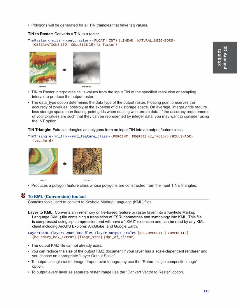
3D A
nalyst toolbox
113
• PolygonswillbegeneratedforallTINtrianglesthathavetagvalues.
TIN to Raster: Converts a TIN to a raster.TinRaster <in_tin> <out_raster> {FLOAT | INT} {LINEAR | NATURAL_NEIGHBORS} {OBSERVATIONS 250 | CELLSIZE 10} {z_factor}
• TINtoRasterinterpolatescellz-valuesfromtheinputTINatthespecifiedresolutionorsamplinginterval to produce the output raster.
• Thedata_typeoptiondeterminesthedatatypeoftheoutputraster.Floatingpointpreservestheaccuracyofz-values,possiblyattheexpenseofdiskstoragespace.Onaverage,integergridsrequirelessstoragespacethanfloating-pointgridswhendealingwithterraindata.Iftheaccuracyrequirementsofyourz-valuesaresuchthattheycanberepresentedbyintegerdata,youmaywanttoconsiderusingthe INT option.
TIN Triangle: Extracts triangles as polygons from an input TIN into an output feature class.TinTriangle <in_tin> <out_feature_class> {PERCENT | DEGREE} {z_factor} {HILLSHADE} {tag_field}
• ProducesapolygonfeatureclasswhosepolygonsareconstructedfromtheinputTIN’striangles.
To KML (Conversion) toolset ContainstoolsusedtoconverttoKeyholeMarkupLanguage(KML)files.
Layer to KML:Convertsanin-memoryorfile-basedfeatureorrasterlayerintoaKeyholeMarkupLanguage(KML)filecontainingatranslationofESRIgeometriesandsymbologyintoKML.Thisfileiscompressedusingzipcompressionandwillhavea“.KMZ”extensionandcanbereadbyanyKMLclientincludingArcGISExplorer,ArcGlobe,andGoogleEarth.
LayerToKML <layer> <out_kmz_file> <layer_output_scale> {No_COMPOSITE| COMPOSITE} {boundary_box_extent} {image_size} {dpi_of_client}
• TheoutputKMZfilecannotalreadyexist.• YoucanreducethesizeoftheoutputKMZdocumentifyourlayerhasascale-dependentrendererandyouchooseanappropriate“LayerOutputScale”.
• Tooutputasinglerasterimagedrapedovertopographyusethe“Returnsinglecompositeimage”option.
• Tooutputeverylayerasseparaterasterimageusethe“ConvertVectortoRaster”option.

3D A
naly
stto
olbo
x
114 ArcGIS 9: Geoprocessing Commands Quick Reference Guide
Map to KML:Convertsanin-memoryMaporMapDocumentintoaKeyholeMarkupLanguage(KML)filecontainingatranslationofESRIgeometriesandsymbologyintoKML.Thisfileiscompressedusingzipcompressionandwillhavea“.KMZ”extensionandcanbereadbyanyKMLclientincludingArcGISExplorer,ArcGlobe,andGoogleEarth.
MapToKML <in_map_document> <data_frame> <out_kmz_file> <map_output_scale> {NO_COMPOSITE| COMPOSITE} {VECTOR_TO_IMAGE | VECTOR_TO_VECTOR} {extent_to_export} {image_size} {dpi_of_client}
• TheoutputKMZfilecannotalreadyexist.• YoucanreducethesizeoftheoutputKMZdocumentifyourmaphasscale-dependentrenderersandyouchooseanappropriate“MapOutputScale”.
• Tooutputasinglerasterimagedrapedovertopographyusethe“Returnsinglecompositeimage”option.
• Tooutputeverylayerasseparaterasterimageusethe“ConvertVectortoRaster”option.
Functional Surface toolset Contains tools to produce output providing knowledge about height information that is contained in surfaces.
Interpolate Shape:Interpolatesz-valuesforafeatureclassbasedonanunderlyingraster,TIN,orterrainsurface.
InterpolateShape <in_surface> <in_feature_class> <out_feature_class> {sample_distance} {z_factor} {method} {DENSIFY | VERTICES_ONLY} {pyramid_level_resolution}
• Interpolatesa3Dfeatureclassfromaninput2Dfeatureclassandasurfacewiththeoverlappingextent.
• Whenusingthenaturalneighborsinterpolationoption,makesuretospecifyareasonablesampledistance. This usually falls between 0.5 and 1.0 times the average point spacing of the data used to build the TIN.
• Whenusingthevertexonlyoption,inputfeatureswithverticesthatfalloutsidethedataareaofthesurface will be ignored and not available in the output. Clip features prior to running the interpolate shape to ensure the features are completely on the surface.
Line of Sight: Calculates the visibility across a surface between points.LineOfSight <in_surface> <in_line_feature_class> <out_los_feature_class> {out_obstruction_feature_class} {NO_CURVATURE | CURVATURE} {NO_REFRACTION | REFRACTION} {refraction_factor} {pyramid_level_resolution}
• Theobserveristhepointfromwhichvisibilityisdetermined.Thetargetistheoppositeendoftheline,towhich visibility is determined.
• Onlytheendpointsoftheinputlineareusedtodeterminetargetvisibility.
Surface Length: Calculates the surface length of each line in a feature class based on a raster or TIN surface.
SurfaceLength <in_surface> <in_feature_class> {out_length_field} {sample_distance} {z_factor}

3D A
nalyst toolbox
115
• Useasmallersamplingdistancetoincreasetheaccuracyofthesurfacelengthcalculations.• Use{out_length_field}togivethelengthfieldacustomname.
Surface Spot: Calculates surface values for each point of a point feature class by interpolating from a raster or TIN surface.
SurfaceSpot <in_surface> <in_feature_class> {out_spot_field} {z_factor} {method}
• Ensuretheinputsurfaceandtheinputfeatureclasshaveoverlappingextents.• Usethe{z_factor}argumenttoconverttheoutputfieldtothedesiredunits.
Surface Volume: Calculates the area and volume of a functional surface above or below a given reference plane.
SurfaceVolume <in_surface> {out_text_file} {ABOVE | BELOW} {base_z} {z_factor}
• TodeterminethevolumeofanisolatedportionofaTINsurface,usetheAddFeatureClassToTINtooltoaddaclippolygondefiningyourstudyarea.
• Usingazfactorisessentialforcorrectvolumecalculationswhenthesurfacezunitsareexpressedinadifferentunitofmeasurethanthegroundunits.Usingazfactordoesnotmodifytheoriginaldata.
Raster Interpolation toolset Contains tools to create a raster surface from point features.
IDW:Interpolatesasurfacefrompointsusinganinversedistanceweighted(IDW)technique.IDW <in_point_features> <z_field> <out_raster> {cell_size} {power} {search_radius} {in_barrier_polyline_features}
• Thebarriersoptionisusedtospecifythelocationoflinearfeaturesknowntointerruptthesurfacecontinuity.Thesefeaturesdonothavez-values.Cliffs,faults,orembankmentsaretypicalexamplesofbarriers.Barrierslimittheselectedsetoftheinputsamplepointsusedtointerpolateoutputz-valuestothose samples on the same side of the barrier as the current processing cell.
3D A
naly
stto
olbo
x
116 ArcGIS 9: Geoprocessing Commands Quick Reference Guide
• TheoutputvalueforacellusingIDWislimitedtotherangeofthevaluesusedtointerpolate.BecauseIDWisaweighteddistanceaverage,theaveragecannotbegreaterthanthehighestorlessthanthelowestinput.Therefore,itcannotcreateridgesorvalleysiftheseextremeshavenotalreadybeensampled(WatsonandPhilip1985).
• ThebestresultsfromIDWareobtainedwhensamplingissufficientlydensewithregardtothelocalvariationyouareattemptingtosimulate.Ifthesamplingofinputpointsissparseoruneven,theresultsmaynotsufficientlyrepresentthedesiredsurface(WatsonandPhilip1985).
Krige: Interpolates a surface from points using kriging.Kriging <in_point_features> <z_field> <out_surface_raster> <semiVariogram_props> {cell_size} {search_radius} {out_variance_prediction_raster}
• Theuniversalkrigingtypes(linearwithlineardriftandlinearwithquadraticdrift)assumethatthereisastructural component present and that the local trend varies from one location to another.
• TheadvancedparametersallowcontrolofthesemivariogramusedforKriging.AdefaultvalueforLagsizeisinitiallysettothedefaultoutputcellsize.Formajorrange,partialsill,andnugget,adefaultvaluewillbecalculatedinternallyifnothingisspecified.
• Lowvalueswithintheoutputvarianceofpredictionrasterindicateahighdegreeofconfidenceinthepredictedvalue.Highvaluesmayindicateaneedformoredatapoints.
Natural Neighbor:Interpolatesasurfacefrompointsusinganaturalneighbortechnique.NaturalNeighbor <in_point_features> <z_field> <out_raster> {cell_size}
• TheNaturalNeighbortoolcanefficientlyhandlelargenumbersofinputpoints.Otherinterpolatorsmayhavedifficultywithlargepointdatasets.
Spline:Interpolatesasurfacefrompointsusingaminimumcurvaturesplinetechnique.Spline <in_point_features> <z_field> <out_raster> {cell_size} {REGULARIZED | TENSION} {weight} {number_points}
• TheresultingsmoothsurfacefromSplinepassesexactlythroughtheinputpoints.• TheREGULARIZEDoptionofSplineusuallyproducessmoothersurfacesthanthosecreatedwiththeTENSIONoption.
• FortheREGULARIZEDoption,highervaluesusedfortheWeightparameterproducesmoothersurfaces.Thevaluesenteredforthisparametermustbeequaltoorgreaterthanzero.Typicalvaluesthatareusedare0,0.001,0.01,0.1,and0.5.TheWeightisthesquareoftheparameter,referredtointheliteratureastau(t).
• FortheTENSIONoption,highervaluesenteredfortheWeightparameterresultinsomewhatcoarsersurfaces but with surfaces that closely conform to the control points. The values entered have to beequaltoorgreaterthanzero.Typicalvaluesare0,1,5,and10.TheWeightisthesquareoftheparameter,referredtointheliteratureasphi(Φ).
• ThegreaterthevalueofNumberofPoints,thesmootherthesurfaceoftheoutputraster.
Spline with Barriers:Interpolatesasurface,usingbarriers,frompointsusingaminimumcurvaturesplinetechnique.Thebarriersareenteredaseitherpolygonorpolylinefeatures.
SplineWithBarriers <in_point_features> <z_field> {in_barrier_features} <output_cell_size> <output_raster> {smoothing_factor}
• ThistoolrequirestheJavaRuntimeEnvironmentVersion5.0,orhigher,tobeinstalled.TheJavaRuntime Environment can be downloaded free from http://www.java.com/en/download.
• Theresultingsmoothsurfacefromthesplinewithbarriertoolisconstrainedbytheinputbarrierfeatures.
• Ifacellsizeofzeroisenteredtheshorterofthewidthortheheightoftheextentoftheinputpointfeaturesintheinputspatialreference,dividedby250,willbeusedasthecellsize.

3D A
nalyst toolbox
117
Topo to Raster: Generates a hydrologically correct raster dataset of elevation.TopoToRaster <feature_layer{Field} {Type};feature_layer{Field} {Type}...> <out_surface_raster> {cell_size} {extent} {Margin} {minimum_z_value} {maximum_z_value} {ENFORCE | NO_ENFORCE | ENFORCE_WITH_SINK} {CONTOUR | SPOT} {maximum_iterations} {roughness_penalty} {discrete_error_factor} {vertical_standard_error} {tolerance_1} {tolerance_2} {out_stream_features} {out_sink_features} {out_diagnostic_file} {out_parameter_file}
• TopotoRasterwillonlyusefourinputdatapointsfortheinterpolationofeachoutputcell.Alladditionalpointsareignored.Iftoomanypointsareencounteredbythealgorithm,anerrormayoccurindicating the point dataset has too many points. The maximum number of points that can be used isnrows*ncols,wherenrowsisthenumberofrowsintheoutputrasterandncolsisthenumberofcolumns.
• Streamdataalwaystakespriorityoverpointorcontourdata;therefore,elevationdatapointsthatconflictwithdescentdowneachstreamareignored.Streamdataisapowerfulwayofaddingtopographicinformationtotheinterpolation,furtherensuringthequalityoftheoutputDEM.
• SometypicalvaluesfortheTolerance1andTolerance2settingsare:• Forpointdataat1:100,000scale,use5.0and200.0.• Forlessdensepointdataatupto1:500,000scale,use10.0and400.0.• Forcontourdatawithcontourspacingof10,use5.0and100.0.
Topo to Raster by File:Interpolatesahydrologicallycorrectsurfacefrompoint,line,andpolygondatausingparametersspecifiedinafile.
TopoToRasterByFile <in_parameter_file> <out_surface_raster> {out_stream_features} {out_sink_features}
• Theinputdataidentifiestheinputdatasetsand,whereapplicable,fields.Therearesixtypesofinput:contours,points,sinks,streams,lakes,andboundaries.Asmanyinputscanbeusedasdesired,withinreason.Theorderinwhichtheinputsareentereddoesnothaveanybearingontheoutcome.<Path>indicatesapathtoadataset,<Item>indicatesafieldname,and<#>indicatesavaluetobeentered.\
• Theparameterfileisstructuredwiththeinputdatasetslistedfirst,followedbythevariousparametersettings,thentheoutputoptions.
Inputs:• Contours—Contourlinedatasetwithitemcontainingheightvalues.
Contour <Path> <Item>
• Points—Pointdatasetwithitemcontainingheightvalues. Point <Path> <Item>
• Sinks—Pointdatasetcontainingsinklocations.Ifthedatasethaselevationvaluesforthesinks,specifythatfieldnameasthe<Item>.Ifonlythelocationsofthesinksaretobeused,useNONEfor<Item>.
Sink <Path> <Item>
• Streams—Streamlinedataset.Heightvaluesarenotnecessary. Stream <Path>
• Lakes—Lakepolygondataset.Heightvaluesarenotnecessary. Lake <Path>
• Boundary—Boundarypolygondataset.Heightvaluesarenotnecessary. Boundary <Path>
Parametersettings:• Enforce—Controlswhetherdrainageenforcementisapplied.
ENFORCE <ON | OFF | ON_WITH_SINK>
• Datatype—Primarytypeofinputdata. DATATYPE <CONTOUR | SPOT>
• Iterations—Themaximumnumberofiterationsthealgorithmperforms. ITERATIONS <#>
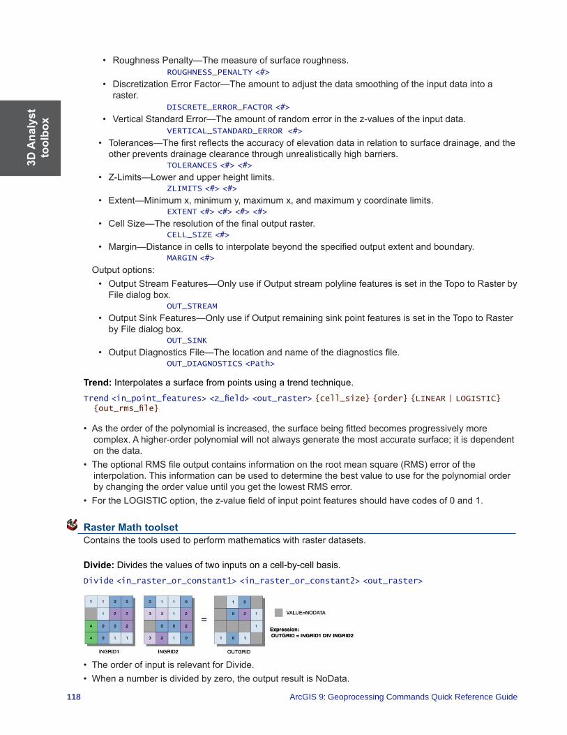
3D A
naly
stto
olbo
x
118 ArcGIS 9: Geoprocessing Commands Quick Reference Guide
• RoughnessPenalty—Themeasureofsurfaceroughness. ROUGHNESS_PENALTY <#>
• DiscretizationErrorFactor—Theamounttoadjustthedatasmoothingoftheinputdataintoaraster.
DISCRETE_ERROR_FACTOR <#>
• VerticalStandardError—Theamountofrandomerrorinthez-valuesoftheinputdata. VERTICAL_STANDARD_ERROR <#>
• Tolerances—Thefirstreflectstheaccuracyofelevationdatainrelationtosurfacedrainage,andtheother prevents drainage clearance through unrealistically high barriers.
TOLERANCES <#> <#>
• Z-Limits—Lowerandupperheightlimits. ZLIMITS <#> <#>
• Extent—Minimumx,minimumy,maximumx,andmaximumycoordinatelimits. EXTENT <#> <#> <#> <#>
• CellSize—Theresolutionofthefinaloutputraster. CELL_SIZE <#>
• Margin—Distanceincellstointerpolatebeyondthespecifiedoutputextentandboundary. MARGIN <#>
Outputoptions:• OutputStreamFeatures—OnlyuseifOutputstreampolylinefeaturesissetintheTopotoRasterbyFiledialogbox.
OUT_STREAM
• OutputSinkFeatures—OnlyuseifOutputremainingsinkpointfeaturesissetintheTopotoRasterbyFiledialogbox.
OUT_SINK
• OutputDiagnosticsFile—Thelocationandnameofthediagnosticsfile. OUT_DIAGNOSTICS <Path>
Trend: Interpolatesasurfacefrompointsusingatrendtechnique.Trend <in_point_features> <z_field> <out_raster> {cell_size} {order} {LINEAR | LOGISTIC} {out_rms_file}
• Astheorderofthepolynomialisincreased,thesurfacebeingfittedbecomesprogressivelymorecomplex. A higher-order polynomial will not always generate the most accurate surface; it is dependent on the data.
• TheoptionalRMSfileoutputcontainsinformationontherootmeansquare(RMS)erroroftheinterpolation. This information can be used to determine the best value to use for the polynomial order by changing the order value until you get the lowest RMS error.
• FortheLOGISTICoption,thez-valuefieldofinputpointfeaturesshouldhavecodesof0and1.
Raster Math toolset Contains the tools used to perform mathematics with raster datasets.
Divide: Divides the values of two inputs on a cell-by-cell basis.Divide <in_raster_or_constant1> <in_raster_or_constant2> <out_raster>
• TheorderofinputisrelevantforDivide.• Whenanumberisdividedbyzero,theoutputresultisNoData.

3D A
nalyst toolbox
119
• Ifbothinputsareintegers,thenDivideperformsanintegerdivisionandtheoutputresultisaninteger.Forexample,if3istobedividedby2,theoutputis1.
• Ifeitherinputisoffloating-pointtype,thenDivideperformsafloating-pointdivision,andtheresultisafloating-pointvalue.Forexample,if3isdividedby2.0,theoutputis1.5.
Float: Convertseachcellvalueofarasterdatasetintoafloating-pointvalue.Float <in_raster_or_constant> <out_raster>
• Inputvaluesareintegersandcanbepositiveornegative.
Int: Converts each cell value of a raster dataset into an integer value through truncation.Int <in_raster_or_constant> <out_raster>
• Ifroundingispreferredratherthantruncating,adda0.5inputrasterpriortoperformingInt.• ThedifferencebetweentheRoundDownandIntfunctionsisthatIntalwaystruncatesanumber:
int on 1.5 becomes 1
int on -1.5 becomes -1
whileforthesametwovalues,RoundDownreturnsround down on 1.5 becomes 1.0
round down on -1.5 becomes -2.0
AseconddifferencebetweenthetwofunctionsisthatRoundDownoutputsfloating-pointvalues,andInt outputs integer values.
Minus:Subtractsthevaluesofthesecondinputfromthevaluesofthefirstinput.Minus <in_raster_or_constant1> <in_raster_or_constant2> <out_raster>
• Theorderofinputisrelevantinthesubtractionexpression.
Plus: Adds the values of two raster datasets on a cell-by-cell basis.Plus <in_raster_or_constant1> <in_raster_or_constant2> <out_raster>
• Theorderofinputisirrelevantintheadditionexpression.
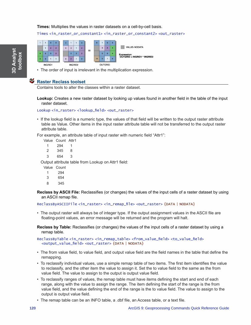
3D A
naly
stto
olbo
x
120 ArcGIS 9: Geoprocessing Commands Quick Reference Guide
Times: Multiplies the values in raster datasets on a cell-by-cell basis.Times <in_raster_or_constant1> <in_raster_or_constant2> <out_raster>
• Theorderofinputisirrelevantinthemultiplicationexpression.
Raster Reclass toolset Contains tools to alter the classes within a raster dataset.
Lookup: Createsanewrasterdatasetbylookingupvaluesfoundinanotherfieldinthetableoftheinputraster dataset.
Lookup <in_raster> <lookup_field> <out_raster>
• Ifthelookupfieldisanumerictype,thevaluesofthatfieldwillbewrittentotheoutputrasterattributetableasValue.Otheritemsintheinputrasterattributetablewillnotbetransferredtotheoutputrasterattribute table.
Forexample,anattributetableofinputrasterwithnumericfield“Attr1”:ValueCountAttr1 1 294 1 2 345 836543
OutputattributetablefromLookuponAttr1field:ValueCount 1 2943654 8 345
Reclass by ASCII File:Reclassifies(orchanges)thevaluesoftheinputcellsofarasterdatasetbyusinganASCIIremapfile.
ReclassByASCIIFile <in_raster> <in_remap_file> <out_raster> {DATA | NODATA}
• Theoutputrasterwillalwaysbeofintegertype.IftheoutputassignmentvaluesintheASCIIfilearefloating-pointvalues,anerrormessagewillbereturnedandtheprogramwillhalt.
Reclass by Table:Reclassifies(orchanges)thevaluesoftheinputcellsofarasterdatasetbyusingaremap table.
ReclassByTable <in_raster> <in_remap_table> <from_value_field> <to_value_field> <output_value_field> <out_raster> {DATA | NODATA}
• Thefromvaluefield,tovaluefield,andoutputvaluefieldarethefieldnamesinthetablethatdefinetheremapping.
• Toreclassifyindividualvalues,useasimpleremaptableoftwoitems.Thefirstitemidentifiesthevaluetoreclassify,andtheotheritemthevaluetoassignit.Setthetovaluefieldtothesameasthefromvaluefield.Thevaluetoassigntotheoutputisoutputvaluefield.
• Toreclassifyrangesofvalues,theremaptablemusthaveitemsdefiningthestartandendofeachrange,alongwiththevaluetoassigntherange.Theitemdefiningthestartoftherangeisthefromvaluefield,andthevaluedefiningtheendoftherangeisthetovaluefield.Thevaluetoassigntotheoutputisoutputvaluefield.
• TheremaptablecanbeanINFOtable,a.dbffile,anAccesstable,oratextfile.

3D A
nalyst toolbox
121
• Thevaluesinthefromandtofieldscanbeanynumericalitem.Theassignmentvaluesintheoutputfieldmustbeintegers.
• Valuesinthefromfieldofthetablemustbesortedinascendingorderandshouldnotoverlap.
Reclassify: Reclassifies(orchanges)thevalueinarasterdataset.Reclassify <in_raster> <reclass_field> <remap> <out_raster> {DATA | NODATA}
• TheremaptablecanbestoredwiththeSavebutton.TheLoadbuttonallowspreviouslycreatedremaptablestobeused.OnlyremaptablescreatedbythetoolshouldbeusedinReclassify.
• IfrunningtheReclassifytoolaspartofamodelwithinaModelBuilderwindow,runthetoolsbeforetheReclassifytoolinthemodelfirst.ThiswillallowthevaluesfortheinputrastertodisplayproperlyintheReclassificationdialogbox.
Slice:Slicesarangeofvaluesoftheinputcellsofarasterbyzonesofequalinterval,equalarea,orbynatural breaks.
Slice <in_raster> <out_raster> <number_zones> {EQUAL_INTERVAL | EQUAL_AREA | NATURAL_BREAKS} {base_output_zone}
• Ifamaskhasbeenset,thosecellsthathavebeenmaskedoutwillreceiveNoDataontheoutputsliceraster.
Raster Surface toolset Containstoolstoanalyzethesurfaceofarasterdataset.
Aspect:Identifiesthedownslopedirectionofthemaximumrateofchangeinvaluefromeachcelltoitsneighbors.
Aspect <in_raster> <out_raster>
• Aspectisthedirectionofthemaximumrateofchangeinthez-valuefromeachcellinarastersurface.• Aspectisexpressedinpositivedegreesfrom0to359.9,measuredclockwisefromthenorth.• Cellsintheinputrasterofzeroslope(forexample,flat)areassignedanaspectof-1.
Contour: Creates contours or isolines from a raster dataset surface.Contour <in_raster> <out_polyline_features> <contour_interval> {base_contour} {z_factor}
• SmootherbutlessaccuratecontoursmaybeobtainedbyfirstperformingaNeighborhoodFocalStatistics operation with the mean option on the input raster.
• Abasecontourisused,forexample,whenyouwanttocreatecontoursevery15meters,startingat10meters.Here,10wouldbeusedforthebasecontour,and15wouldbethecontourinterval.Thevaluestobecontouredwouldbe10,25,40,55,andsoon.
• Specifyingabasecontourdoesnotpreventcontoursfrombeingcreatedaboveorbelowthatvalue.
Contour List: Creates contours or isolines from a list of contour values.ContourList <in_raster> <out_polyline_features> <contour_values;contour_values...>
• SmootherbutlessaccuratecontoursmaybeobtainedbyfirstperformingaNeighborhoodFocalStatistics operation with the mean option on the input raster.

3D A
naly
stto
olbo
x
122 ArcGIS 9: Geoprocessing Commands Quick Reference Guide
Contour with Barriers: Creates contours from a raster surface. The inclusion of barrier features allows you to independently generate contours on either side of a barrier.
ContourwithBarriers <in_raster> <out_contour_feature_class> {in_barrier_features} {POLYLINES | POLYGONS} {in_contour_values_file} {NO_EXPLICIT_VALUES_ONLY | EXPLICIT_VALUES_ONLY} {in_base_contour} <in_contour_interval> <in_indexed_contour_interval>
<in_contour_list; in_contour_list...> {in_z_factor}
Curvature: Calculatesthecurvatureofarastersurface,optionallyincludingprofileandplancurvature.Curvature <in_raster> <out_curvature_raster> {z_factor} {out_profile_curve_raster} {out_plan_curve_raster}
• Theprimaryoutputisthecurvatureofthesurfaceonacell-by-cellbasis,asfittedthroughthatcellanditseightsurroundingneighbors.Curvatureisthesecondderivativeofthesurface,orthe“slopeoftheslope.”Twooptionaloutputcurvaturetypesarepossible;theprofilecurvatureisinthedirectionofthemaximumslope,andtheplancurvatureisperpendiculartothedirectionofthemaximumslope.
• Apositivecurvatureindicatesthatthesurfaceisupwardlyconvexatthatcell.Anegativecurvatureindicatesthatthesurfaceisupwardlyconcaveatthatcell.Avalueofzeroindicatesthatthesurfaceisflat.
• Intheprofileoutput,anegativevalueindicatesthatthesurfaceisupwardlyconvexatthatcell.Apositiveprofileindicatesthatthesurfaceisupwardlyconcaveatthatcell.Avalueofzeroindicatesthatthesurfaceisflat.
• Intheplanoutput,apositivevalueindicatesthatthesurfaceisupwardlyconvexatthatcell.Anegativeplanindicatesthatthesurfaceisupwardlyconcaveatthatcell.Avalueofzeroindicatesthatthesurfaceisflat.
• UnitsoftheCurvatureoutputraster,aswellastheunitsfortheoptionaloutputprofilecurverasterandoutputplancurveraster,areoneover100zunits,or1/100(zunits).Thereasonablyexpectedvaluesofallthreeoutputrastersforahillyarea(moderaterelief)maydifferfromabout-0.5to0.5,whileforthesteep,ruggedmountains(extremerelief),thevaluesmayvarybetween-4and4.
Cut/Fill:Calculatescutandfillareas.CutFill <in_before_surface> <in_after_surface> <out_raster> {z_factor}
• TheCut/Filltoolenablesyoutocreateamapbasedontwoinputsurfaces(beforeandafter),displayingtheareasandvolumesofsurfacematerialsthathavebeenmodifiedbytheadditionorremovalofsurfacematerial.Negativez-valuesindicateregionsoftheinputbeforerastersurfacethathavebeenfilled;positiveregionsindicatecuts.
• TogetaccurateCut/Fillresults,thezunitsshouldbethesameasthex,ygroundunits.Thisensuresthattheresultingvolumesaremeaningfulcubicmeasures(forexample,cubicmeters).Iftheyarenotthesame,useaz-factortoconvertzunitstox,yunits.Forexample,ifyourx,yunitsaremetersandyourzunitsarefeet,youcouldspecifyaz-factorof0.3048toconvertfeettometers.
Hillshade: Computes hillshade values for a raster surface by considering the illumination angle and shadows.
HillShade <in_raster> <out_raster> {azimuth} {altitude} {NO_SHADOWS | SHADOWS} {z_factor}
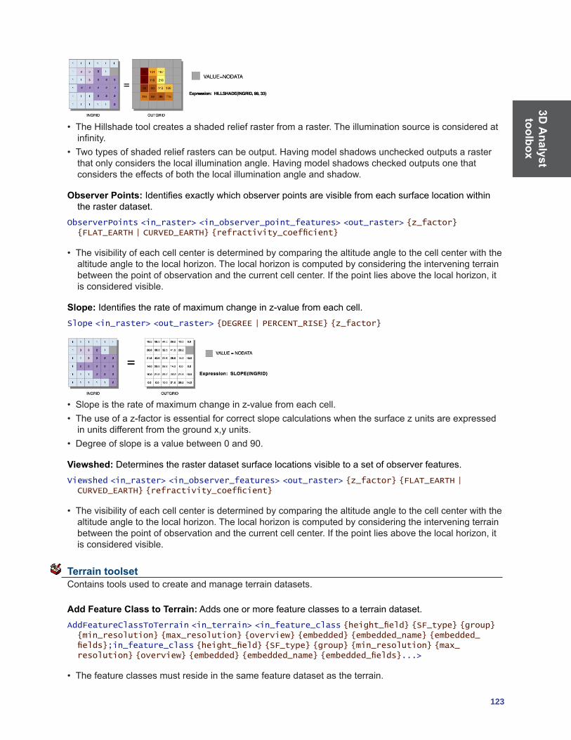
3D A
nalyst toolbox
123
• TheHillshadetoolcreatesashadedreliefrasterfromaraster.Theilluminationsourceisconsideredatinfinity.
• Twotypesofshadedreliefrasterscanbeoutput.Havingmodelshadowsuncheckedoutputsarasterthatonlyconsidersthelocalilluminationangle.Havingmodelshadowscheckedoutputsonethatconsiders the effects of both the local illumination angle and shadow.
Observer Points:Identifiesexactlywhichobserverpointsarevisiblefromeachsurfacelocationwithinthe raster dataset.
ObserverPoints <in_raster> <in_observer_point_features> <out_raster> {z_factor} {FLAT_EARTH | CURVED_EARTH} {refractivity_coefficient}
• Thevisibilityofeachcellcenterisdeterminedbycomparingthealtitudeangletothecellcenterwiththealtitudeangletothelocalhorizon.Thelocalhorizoniscomputedbyconsideringtheinterveningterrainbetweenthepointofobservationandthecurrentcellcenter.Ifthepointliesabovethelocalhorizon,itis considered visible.
Slope:Identifiestherateofmaximumchangeinz-valuefromeachcell.Slope <in_raster> <out_raster> {DEGREE | PERCENT_RISE} {z_factor}
• Slopeistherateofmaximumchangeinz-valuefromeachcell.• Theuseofaz-factorisessentialforcorrectslopecalculationswhenthesurfacezunitsareexpressedinunitsdifferentfromthegroundx,yunits.
• Degreeofslopeisavaluebetween0and90.
Viewshed: Determines the raster dataset surface locations visible to a set of observer features.Viewshed <in_raster> <in_observer_features> <out_raster> {z_factor} {FLAT_EARTH | CURVED_EARTH} {refractivity_coefficient}
• Thevisibilityofeachcellcenterisdeterminedbycomparingthealtitudeangletothecellcenterwiththealtitudeangletothelocalhorizon.Thelocalhorizoniscomputedbyconsideringtheinterveningterrainbetweenthepointofobservationandthecurrentcellcenter.Ifthepointliesabovethelocalhorizon,itis considered visible.
Terrain toolset Contains tools used to create and manage terrain datasets.
Add Feature Class to Terrain: Adds one or more feature classes to a terrain dataset.AddFeatureClassToTerrain <in_terrain> <in_feature_class {height_field} {SF_type} {group} {min_resolution} {max_resolution} {overview} {embedded} {embedded_name} {embedded_fields};in_feature_class {height_field} {SF_type} {group} {min_resolution} {max_resolution} {overview} {embedded} {embedded_name} {embedded_fields}...>
• Thefeatureclassesmustresideinthesamefeaturedatasetastheterrain.

3D A
naly
stto
olbo
x
124 ArcGIS 9: Geoprocessing Commands Quick Reference Guide
• Addinganewfeatureclasstoaterraininvalidatesit.UsetheBuildTerraintoolafteraddingfeatureclasses.
• Theinputterraincannotberegisteredasversioned.• Theinputfeatureclasscannotberegisteredasversioned.
Add Terrain Points: Adds multipoints to an embedded terrain feature class by appending them or by using them to replace existing multipoints that fall within the same extent.
AddTerrainPoints <in_terrain> <terrain_feature_class> <in_feature_class> {APPEND | REPLACE}
• Thistoolfunctionsonlyonfeatureclassesembeddedinaterrain.Theterrainandtheembeddedfeature class must already exist.
• Ifyouwanttoaddpointstoaregularfeatureclasspotentiallyreferencedbyaterrainbutnotembeddedinit,usetheAppendtool.
• Addingpointstoanembeddedfeatureclasswillinvalidatetheterrain.RunBuildTerrainafteraddingpoints.
Add Terrain Pyramid Level: Adds a new pyramid level to an existing terrain dataset.AddTerrainPyramidLevel <in_terrain> <ZTOLERANCE> <pyramid_level_definition;pyramid_level_definition...>
• Addinganewpyramidleveltoaterraininvalidatesit.UsetheBuildTerraintoolafteraddingapyramidlevel.
• Theinputterraincannotberegisteredasversioned.
Build Terrain:Performsthenecessarystepstomakeaterrainusableafterit’sinitiallydefined.BuildTerrain <in_terrain>
• Willperformtheworknecessarytoupdatetheterrainrelativetoanyedits.Theseincludemodificationstoterrainschema(forexample,featureclassparticipation,pyramiddefinition)ortogeometryinassociatedfeatureclasses.It’smoreefficienttomakeacollectionofeditsfollowedbyonebuildratherthan running a build after each individual edit.
Change Terrain Reference Scale: Changes the reference scale used by a terrain pyramid level.ChangeTerrainReferenceScale <in_terrain> <old_refscale> <new_refscale>
• Thistoolisusefulwhenanexistingreferencescaleassociatedwithaterrainpyramidlevelisknowntobe inappropriate and needs to be reset.
• Toaddorremoveapyramidlevel,ratherthanchangethedefinitionofanexistingpyramidlevel,usetheAddTerrainPyramidorRemoveTerrainPyramidtools.
Create Terrain:Createsanewterraindatasetinsidethespecifiedfeaturedataset.CreateTerrain <in_feature_dataset> <out_terrain_name> <average_point_spacing> {max_overview_size} {config_keyword} {WINDOWSIZE | ZTOLERANCE} {ZMIN | ZMAX | ZMEAN | ZMINMAX} {NONE | MILD | MODERATE | STRONG} {secondary_thinning_threshold}
• ThistoolisgearedtowarddataautomationforuseinscriptsandModelBuilder.ConsiderusingtheTerrainwizardinArcCatalogforinteractivelycreatinganewterrain.
• TheAveragePointSpacingparameterneedstobedeterminedbythedatathatwillbeusedtobuildtheterrain.Thisvaluedoesn’tneedtobeexactbutshouldrepresentagoodapproximation.Ifthedatahasbeengatheredatsignificantlydifferentdensitiesfromonelocationtoanother,givemoreweighttothesmaller spacing.

3D A
nalyst toolbox
125
Remove Feature Class from Terrain: Removes reference to a feature class participating in a terrain dataset.
RemoveFeatureClassFromTerrain <in_terrain> <feature_class>
• Thistooldoesnotdeletethefeatureclass.Rather,iteliminatestheterraindataset’sreferencetoit.• Ifthefeatureclassisembeddedintheterrain,itwillbeextractedanddereferenced.• TheterrainwillneedtoberebuiltusingBuildTerrainafterusingthistool.
Remove Terrain Points: Removes points within an area of interest from one or more embedded feature classes.
RemoveTerrainPoints <in_terrain> <data_source;data_source...> <aoi_extents>
• Thistoolfunctionsonlyonfeatureclassesembeddedinaterrain.Theterrainandatleastoneembedded feature class must already exist.
• Arectangularareaofinterest(AOI)isrequired.Thisdefinestheareaintheembeddedfeatureclasswheremultipointverticeswillbedeleted.IfamultipointcrossestheAOIboundary,onlythoseverticeswithin the boundary will be deleted.
• RemoveTerrainPointslooksforanexistingeditsessiontopiggy-backon.Thissupportsundoiftheeditsessionwasinitializedtosupportundo(forexample,usingtheEditorinsideArcMap).Ifthere’snoeditsession,itstartsandstopsoneitself,inwhichcasethereisnochanceforanundo.
• Removingpointsfromanembeddedfeatureclasswillinvalidatetheterrain.RunBuildTerrainafteradding points.
Remove Terrain Pyramid Level: Removes a pyramid level from a terrain dataset.RemoveTerrainPyramidLevel <in_terrain> <resolution>
• Youhavetheoptionofremovinganybutthehighestresolutionpyramid(level0).• WhenusedinanArcSDEdatabase,theinputterraincannotberegisteredasversioned.
TIN Creation toolset Contains tools to create and edit TINs.
Create TIN: Creates an empty TIN with an extent based on an input geographic dataset.CreateTin <out_tin> <spatial_reference>
• TheoutputTINcannotalreadyexist.• UsetheImportbuttononthespatialreferencedialogboxtobrowsefortheregionoftheTINyouarecreating,orwhenusingthecommandline,indicateadatasetwithacoordinatesystemclosetothatofthe region of the TIN you are creating.
• ToaddfeaturestotheoutputTIN,usetheEditTINtool.
Delineate TIN Data Area:DefinesthedataareaorinterpolationzoneofaTINbasedontriangleedgelength.
DelineateTinDataArea <in_tin> <max_edge_length> {PERIMETER_ONLY | ALL}

3D A
naly
stto
olbo
x
126 ArcGIS 9: Geoprocessing Commands Quick Reference Guide
• ThistoolmodifiestheinputTIN.Ifyouwouldprefernottomodifytheinput,usethestandardCopytooland operate on the copied TIN.
• Thevaluefor<max_edge_length>isbestdeterminedfromtheaveragespacingofnodesintheTINwithinareasthatareconsideredtobevaliddatazones.Provideavaluethatislargerthantheaveragespacing.
Edit TIN: Adds feature classes to an existing TIN and creates surface features of a TIN based on an input feature class.
EditTin <in_tin> <in_feature_class {height_field} {tag_field} {SF_type} {use_z}; in_feature_class {height_field} {tag_field} {SF_type} {use_z}...>
• Multiplefeatureclassescanbeaddedatthesametime.• BeforefeaturescanbeaddedtoaTIN,theTINmustbedefinedusingtheCreateTINtool.• FeaturesmaybeaddedtoanewlycreatedorexistingTIN.
TIN Surface toolset ContainstoolstoanalyzethesurfaceofaTINdataset.
Decimate TIN Nodes: ProducesaTINthatisageneralizedversionofanother.DecimateTinNodes <in_tin> <out_tin> <method> {NO_BREAKLINES | BREAKLINES}
• AsubsetofnodesfromaninputTINisselectedtoproducethenewTIN.
Extrude Between: Converts polygons into multipatches by extruding them between two input TINs.ExtrudeBetween <in_tin1> <in_tin2> <in_feature_class> <out_feature_class>
• Theoutputmultipatchesarewrittentoanewfeatureclass.• TheinputTINsandpolygonsmustalloverlapinhorizontalextenttoproduceanyoutput.
Interpolate Polygon to Multipatch: Creates surface-conforming areal features by extracting those portions of a surface that fall within the extent of input polygons as multipatches.
InterpolatePolyToPatch <in_tin> <in_feature_class> <out_feature_class> {max_strip_size} {z_factor} {area_field} {surface_area_field}

3D A
nalyst toolbox
127
• Theattributesfromtheinputfeaturesarecopiedtotheoutput.Planimetricandsurfaceareaiscalculated for each feature and added as attribution to the output.
• Convertpolygonstomultipatchesifyouarehavingdisplayproblemswithpolygonsconformingtoasurface.
• Themax_strip_sizevaluemustbethreeorlarger.Therecommendedrangeisbetween128and2048.
TIN Aspect: Extracts aspect information from an input TIN into an output feature class.TinAspect <in_tin> <out_feature_class> {class_breaks_table} {aspect_field}
• Aspectisexpressedindegrees.
TIN Contour: Creates a feature class containing a set of contours generated from a functional surface.TinContour <in_tin> <out_feature_class> <interval> {base_contour} {contour_field} {contour_field_precision} {index_interval} {index_interval_field} {z_factor}
• Usetheintervalandbasecontouroptionstotailortheextentandresolutionoftheoutputfeatureclass.• Usetheoutcontourfieldastheheightsourcefordisplayingthecontoursin3D.
TIN Difference: Calculates the volumetric difference between two TINs.TinDifference <in_tin1> <in_tin2> <out_feature_class>
• TheinputTINsneedtooverlapinhorizontalextent.• It’sbestifthehorizontalandverticalcoordinatesystemsoftheinputTINsarethesame.
TIN Polygon Volume: Calculates the volumetric and surface area between polygons of an input feature class and a TIN surface.
TinPolygonVolume <in_tin> <in_feature_class> <in_height_field> {BELOW | ABOVE} {out_volume_field} {surface_area_field}
• TheinputpolygonsandTINneedtooverlapinhorizontalextentforsurfaceareaorvolumetobecalculated.
TIN Slope: Calculates the slope of the surface as the maximum rate of change in elevation across each triangle.
TinSlope <in_tin> <out_feature_class> {PERCENT | DEGREE} {class_breaks_table} {slope_field} {z_factor}

3D A
naly
stto
olbo
x
128 ArcGIS 9: Geoprocessing Commands Quick Reference Guide
• Usetheclass_breaks_tableparametertoconstrainslopeinformationintospecificbreakintervalsoftheoutput feature class.
• Unitsareonlyhonoredwhenusingaclassbreakstable.

129
Data
Interoperability toolbox
Data Interoperability toolbox Contains tools to import and export data with the ArcGIS Data Interoperability extension.
Quick Export: Converts one or more input feature classes or feature layers into any format supported by the ArcGIS Data Interoperability extension.
QuickExport <input;input...> <output>
• ThistoolisusedeithertoexportdatafromArcGISorasthefinalstepinamodelorscriptwherethedestination data is external to ArcGIS.
• Duringtheexport,nochangetothedatamodelismade;ifthisisdesired,acustomdataexporttoolshould be created and used.
Quick Import: Converts data from any format supported by the ArcGIS Data Interoperability extension into a personal geodatabase.
QuickImport <input> <output>
• ThistoolisusedeithertobringdataintotheArcGISenvironmentorasthebeginningpointinamodelor script where data from outside ArcGIS will be processed.
• Thefeatureclassesgenerateddependontheinputdata.Forinstance,ifyouimporttwoMapInfoMIF/MID®files,twofeatureclasseswillbecreated.
• Thistoolcreatesanewpersonalgeodatabaseandwillnotappendtoanexistingone.• ThefeatureclassesgeneratedfromtheimporteddatacanbeaccessedusingtheSelectDatatoolon
the output staging personal geodatabase.• Asdataisimported,nochangestothedatamodelaremade.Totransformthedatamodelduringimport,aCustomDataImportToolshouldbecreatedandused.


131
Geostatistical
Analyst
toolbox Geostatistical Analyst toolbox Contains tools for exploratory spatial data analysis.
Calculate Z-Value: Uses the interpolation model in a geostatistical layer to predict a value at a single location.
GACalculateZValue <in_geostat_layer> <point_coord>
• Thistoolisgenerallyusedinamodelorinscripting.
Create Geostatistical Layer:Usesanexistinggeostatisticallayertocreateanewlayer,whichincludesanew feature dataset or variable.
GACreateGeostatisticalLayer <in_ga_model_source> <in_datasets> <out_layer>
• Geostatisticalmodelsourceiseitherageostatisticallayerorageostatisticalmodel(XML).• Thedatasetusedtocreatethegeostatisticallayerispersistedinthelayer.However,whenanXMLversionissaved,onlythemodelparametersaresavedandnotthedatasetinformation.
GA Layer to Contour: Exports a geostatistical layer to contours.GALayerToContour <in_geostat_layer> <CONTOUR | FILLED CONTOUR> <out_feature_class> {Draft | Presentation}
• Youcanchoosetodisplaythecontoursineitherdraftorpresentationquality.• CONTOURisthecontourorisolinerepresentationofthegeostatisticallayer.Youcandisplaythelinesineitherdraftorpresentationquality.
• FILLED_CONTOURisthepolygonrepresentationofthegeostatisticallayer.Itisassumedforthegraphical display that the values between each contour line are the same for all locations within the polygon.Youcandisplaythelinesineitherdraftorpresentationquality.
GA Layer to Grid: Exports a geostatistical layer to a grid.GALayerToGrid <in_geostat_layer> <out_surface_grid> <cell_size> <points_per_block_horz> <points_per_block_vert>
• Theoutputgridwillbecreatedatthecellsizespecifiedbyoutputcellsize.• Selectthenumberofpredictionsforeachcellinthehorizontalandverticaldirectionsforblock
interpolation.
GA Layer to Points: Exports a geostatistical layer to points.GALayerToPoints <in_geostat_layer> <in_locations> {z_field} <out_feature_class>
• Ifafieldisleftblank,predictionswillbemadeatthelocationpoints.• Ifafieldisselected,predictionswillbemadeandcomparedtothevaluesintheZ_value_fieldanda
validation analysis is performed.
Gaussian Geostatistical Simulations:Performsconditionalorunconditionalgeostatisticalsimulationbased on a Simple Kriging model.
GaussianGeostatisticalSimulations <in_geostat_layer> <number_of_realizations> <output_workspace> <output_simulation_prefix> {in_conditioning_features} {conditioning_field} {cell_size} {in_bounding_dataset} {save_simulated_rasters} {quantile} {threshold} {in_stats_polygons} {MIN | MAX | MEAN | STDDEV | QUARTILE1| MEDIAN | QUARTILE3| QUANTILE | P_THRSHLD}
• ThegeostatisticallayerusedasinputmustbetheresultofperformingSimpleKrigingonadataset.Geostatistical layers resulting from other types of kriging should not be used with this tool. Additionally: • Forpointdataat1:100,000scale,use5.0and200.0.

Geo
stat
istic
al
Ana
lyst
to
olbo
x
132 ArcGIS 9: Geoprocessing Commands Quick Reference Guide
• ANormalScoretransformofthedataisnecessarytoguaranteethattheinputdatafollowsastandard normal distribution.
• Clustereddatashouldbedeclustered(usingeitherthecellorpolygonwithaclippingoutlinemethod)sothattheinputhistogramaccuratelyrepresentsthesampledpopulation.Thishistogramwillbereproducedintherealizations.
• Togenerateconditionalrealizations,theconditioningdatashouldbethesameasthedatathatwasusedtoconstructtheSimpleKrigingmodelthatthesimulationwillbebasedon.However,otherdatasetscanbeusedtoconditiontherealizations.
• Outputgeneratedcanbeidentifiedasfollows:• Theprefixfollowedbys0tosN(whereNisthenumberofrealizations)isusedtonamethesimulatedrasterswhentheoptionsave_simulated_rastersisused.
• TheprefixfollowedbyMIN,MAX,MEAN,STDDEV,QUARTILE1,MEDIAN,QUARTILE3,QUANTILEorP_THRSHLDisusedtonametheoutputrasterswhenthesepostprocessingoptionshave been selected.
• Theprefixfollowedbythepolygonfeatureclassnameisusedtonametheoutputpolygonfeatureclasswhenpostprocessingforareasofinterest(statisticalpolygons)hasbeenselected.
Get Model Parameter: Gets model parameter value from an existing geostatistical model source.
GAGetModelParameter <in_ga_model_source> <model_param_xpath>
• Thistoolisgenerallyusedinamodelorinscripting.• Thegeostatisticalmodelsourceiseitherageostatisticallayerorageostatisticalmodel(XML).
Moving Window Kriging: Automatically estimates the kriging model for each neighborhood as the kriging interpolation moves through all the location points.
GAMovingWindowKriging <in_ga_model_source> <in_datasets> <in_locations> <neighbors_max> <out_feature_class> {cell_size} {out_surface_grid}
• Thegeostatisticalmodelsourceiseitherageostatisticallayerorageostatisticalmodel(XML).• Theinputdatasetmusthavemorethan10points.However,itisrecommendedthatithasmorethan
300 points.
Neighborhood Selection:Createsalayerofpointsbasedonauser-definedneighborhood.GANeighborhoodSelection <in_dataset> <out_layer> <point_coord> <neighbors_max> <neighbors_min> <minor_semiaxis> <major_semiaxis> <angle> {ONE SECTOR | FOUR SECTORS |
FOUR SECTORS SHIFTED | EIGHT SECTORS}
Semivariogram Sensitivity:VariesthesemivariogramparametersNugget,PartialSill,andRangetoperform a sensitivity analysis.
GASemivariogramSensitivity <in_ga_model_source> <in_datasets> <in_locations> {nugget_span_percents} {nugget_calc_times} {partialsill_span_percents} {partialsill_calc_times} {range_span_percents} {range_calc_times} {minrange_span_percents} {minrange_calc_times} <out_table>
• Thegeostatisticalmodelsourceiseitherageostatisticallayerorageostatisticalmodel(XML).
Set Model Parameter: Sets parameter value in an existing geostatistical model source.GASetModelParameter <in_ga_model_source> <model_param_xpath> <in_param_value> <out_ga_model>
• Thistoolisgenerallyusedinamodelorinscripting.• Thegeostatisticalmodelsourceiseitherageostatisticallayerorageostatisticalmodel(XML).

Netw
orkA
nalysttoolbox
133
Network Analyst toolbox Containstoolsfornetworkanalysis,buildingnetworks,andcreatingandeditingturns.
Analysis toolset Contains tools used to perform analysis when using the Network Analyst extension.
Add Field To Analysis Layer:Addsafieldtoanetworkanalysislayer.AddFieldToAnalysisLayer <in_network_analysis_layer> <sub_layer> <field_name> <LONG | TEXT | FLOAT | DOUBLE | SHORT | DATE | BLOB> {field_precision} {field_scale} {field_length} {field_alias} {NULLABLE | NON_NULLABLE}
• Fieldscanbeaddedtoanyofthesublayersofthenetworkanalysislayers.ThesefieldscanbeupdatedwithvaluesandmappedtovariousfieldmappingsoftheAddLocationstoolstoprovideinputstothenetwork analysis layer.
Add Locations: Adds network locations to a network analysis layer.AddLocations <in_network_analysis_layer> <sub_layer> <in_table> <field_mappings> <search_tolerance> {sort_field} {source {snap type};source {snap type}...} {MATCH_TO_CLOSEST | PRIORITY} {APPEND | CLEAR} {NO_SNAP | SNAP} {snap_offset}
• AddLocationscanberunrepeatedlytoappendlocationstothesamesublayer.Forexample,ifstopsforaroutelayercomefromtwofeatureclasses,AddLocationscanbecalledtwicebyusingtheAPPENDoption.
Calculate Locations:Calculatesthenetworklocationfieldsforapointfeatureclass.CalculateLocations <in_point_features> <in_network_dataset> <search_tolerance> <source {snap type};source {snap type}...> {MATCH_TO_CLOSEST | PRIORITY} {source_ID_field} {source_OID_field} {position_field} {side_field} {snap_X_field} {snap_Y_field} {distance_field}
• Calculatelocationsshouldbeusedonpointdatathatwillbeusedmorethanonceasinputtoanetworkanalysislayer.Oncethelocationshavebeencomputed,theAddLocationstoolallowstheUseNetworkLocationFieldsinsteadofGeometrytobeusedtoloadthelocationsveryquickly.
Directions: Generates directions information for a network analysis layer with routes. The directions informationiswrittentoafileineitherXMLortextformat.
Directions <in_network_analysis_layer> <XML | TEXT> <out_directions_file> <FEET | YARDS | MILES | METERS | KILOMETERS | NAUTICALMILES> {REPORT_TIME | NO_REPORT_TIME} {time_attribute}
• Directionscannotbegeneratedforanalysislayerfiles(.lyr),onlyforanalysislayersintheArcMaptableofcontentsorlayerscreatedinthesameapplicationsession,script,ormodelastheDirectionscommand is run.
Make Closest Facility Layer: Makes a closest facility network analysis layer and sets its navigation properties.
MakeClosestFacilityLayer <in_network_dataset> <out_network_analysis_layer> <impedance_attribute> {TRAVEL_TO | TRAVEL_FROM} {default_cutoff} {default_number_facilities_to_find} {accumulate_attribute_name; accumulate_attribute_name...} {ALLOW_UTURNS | NO_UTURNS | ALLOW_DEAD_ENDS_ONLY} {restriction_attribute_name; restriction_attribute_name...} {USE_HIERARCHY | NO_HIERARCHY} {hierarchy_settings} {TRUE_LINES_WITH_MEASURES | NO_LINES | STRAIGHT_LINES | TRUE_LINES_WITHOUT_MEASURES}
• AclosestfacilitylayercanbemadeonanetworkcurrentlyaddedtotheArcMaptableofcontents,oryou can browse to a network dataset on disk.

Net
wor
k A
naly
st
tool
box
134 ArcGIS 9: Geoprocessing Commands Quick Reference Guide
• Hierarchyoptionscanonlybesetiftheinputanalysisnetworkhasahierarchyattribute.
Make OD Cost Matrix Layer:Makesanoriginanddestination(OD)costmatrixlayerandsetsitsnavigation properties.
MakeODCostMatrixLayer <in_network_dataset> <out_network_analysis_layer> <impedance_attribute> {default_cutoff} {default_number_destinations_to_find} {accumulate_attribute_name; accumulate_attribute_name...} {ALLOW_UTURNS | NO_UTURNS | ALLOW_DEAD_ENDS_ONLY} {restriction_attribute_name; restriction_attribute_name...} {USE_HIERARCHY | NO_HIERARCHY} {hierarchy_settings} {STRAIGHT_LINE | NO_LINES}
• AnODcostmatrixlayercanbemadeonanetworkcurrentlyaddedtotheArcMaptableofcontentsoron a network dataset on disk.
• Hierarchyoptionscanonlybesetiftheinputanalysisnetworkhasahierarchyattribute.
Make Route Layer: Makes a route network analysis layer and sets its navigation properties.MakeRouteLayer <in_network_dataset> <out_network_analysis_layer> <impedance_attribute> {USE_INPUT_ORDER | FIND_BEST_ORDER} {PRESERVE_BOTH | PRESERVE_NONE | PRESERVE_FIRST | PRESERVE_LAST} {NO_TIMEWINDOWS | USE_TIMEWINDOWS} {accumulate_attribute_name;accumulate_attribute_name...} {ALLOW_UTURNS | NO_UTURNS | ALLOW_DEAD_ENDS_ONLY} {restriction_attribute_name;restriction_attribute_name...} {USE_HIERARCHY | NO_HIERARCHY} {hierarchy_settings} {TRUE_LINES_WITH_MEASURES | NO_LINES | STRAIGHT_LINES | TRUE_LINES_WITHOUT_MEASURES} {start_date_time}
• TheroutelayercanbemadeonanetworkcurrentlyaddedtotheArcMaptableofcontentsoronanetwork dataset on disk.
• Hierarchyoptionscanonlybesetiftheinputanalysisnetworkhasahierarchyattribute.
Make Service Area Layer: Makes a service area network analysis layer and sets its navigation properties.
MakeServiceAreaLayer <in_network_dataset> <out_network_analysis_layer> <impedance_attribute> {TRAVEL_FROM | TRAVEL_TO} {default_break_values} {SIMPLE_POLYS | DETAILED_POLYS | NO_POLYS} {NO_MERGE | NO_OVERLAP | MERGE} {RINGS | DISKS} {NO_LINES | TRUE_LINES | TRUE_LINES_WITH_MEASURES} {OVERLAP | NON_OVERLAP} {NO_SPLIT | SPLIT} {excluded_source_name;excluded_source_name...} {accumulate_attribute_name;accumulate_attribute_name...} {ALLOW_UTURNS | NO_UTURNS | ALLOW_DEAD_ENDS_ONLY} {restriction_attribute_name;restriction_attribute_name...} {TRIM_POLYS | NO_TRIM_POLYS} {poly_trim_value} {NO_LINES_SOURCE_FIELDS | LINES_SOURCE_FIELDS}
• TheservicearealayercanbemadeonanetworkcurrentlyaddedtotheArcMaptableofcontentsorona network dataset on disk.
• Hierarchyoptionscanonlybesetiftheinputanalysisnetworkhasahierarchyattribute.
Make Vehicle Route Problem Layer:Createsavehicleroutingproblem(VRP)networkanalysislayerand sets its analysis properties.
MakeVehicleRoutingProblemLayer <in_network_dataset> <out_network_analysis_layer> <time_impedance> {distance_impedance} {Minutes | Seconds | Hours | Days} {MILES | KILOMETERS | FEET | YARDS | METERS | INCHES | CENTIMETERS | MILLIMETERS | DECIMETERS | NAUTICALMILES | DECIMALDEGREES} {default_date} {capacity_count} {MEDIUM | HIGH | LOW} {MEDIUM | HIGH | LOW} {ALLOW_UTURNS | NO_UTURNS | ALLOW_DEAD_ENDS_ONLY} {restriction_attribute_name;restriction_attribute_name...} {NO_HIERARCHY | USE_HIERARCHY} {hierarchy_settings} {TRUE_LINES_WITH_MEASURES | TRUE_LINES_WITHOUT_MEASURES | STRAIGHT_LINES | NO_LINES}
• Avehicleroutingproblemanalysislayercanbeusedtosolvecommonfleetmanagementproblemssuchasservicingasetofordersusingafleetofvehicles.
• ThevehicleroutingproblemlayercanbemadeonanetworkdatasetcurrentlyaddedtotheArcMaptable of contents or on a network dataset on disk.

Netw
orkA
nalysttoolbox
135
• Hierarchyoptionscanonlybesetiftheinputanalysisnetworkhasahierarchyattribute.
Solve:Performstheanalysisappropriatetothenetworkanalysislayeronwhichitisexecuted.Solve <in_network_analsis_layer> {SKIP | HALT}
• BesuretospecifyalltheparametersnecessarytoperformtheanalysisbeforerunningSolve.
Network Dataset toolset Contains a tool used to build network datasets.
Build Network: Reconstructs the network connectivity and attribute information of a network dataset.BuildNetwork <in_nework_dataset>
• YoucanbuildthenetworkwithoutstartingArcCatalogaftermakingeditstotheattributesorthefeaturesof a participating source feature class.
Turn Feature Class toolset Contains tools used to build and edit turn data.
Create Turn Feature Class: Creates a new turn feature class.CreateTurnFeatureClass <out_location> <out_feature_class_name> {maximum_edges} {in_network_dataset} {in_template_feature_class} {spatial_reference} {config_keyword} {spatial_grid_1} {spatial_grid_2} {spatial_grid_3}
Increase Maximum Edges: Increases the maximum number of edges in a turn feature class.IncreaseMaximumEdges <in_turn_features> <maximum_edges>
• Oncethemaximumnumberofedgesisincreased,itcannotbedecreasedlater.Soonlyincreasebytheneeded amount.
• Increasingthenumberofedgesbyoneaddsthreeadditionalfieldstotheturnfeatureclass.Takecarenottoexceedthemaximumnumberoffieldsallowedbythedatabasebeingused.Forexample,personalgeodatabaseislimitedto255fields.
Populate Alternate ID Fields:Createsandpopulatesadditionalfieldsontheturnfeatureclass(es)inanetwork dataset that reference the edges by alternate IDs.
PopulateAlternateIDFields <in_network_dataset> <alternate_ID_field_name>
• ThealternateIDsallowforanothersetofIDsthatcanhelpmaintaintheintegrityoftheturnfeaturesincase the source edges are being edited.
Turn Table to Turn Feature Class:ConvertsanArcViewGISturntableorArcInfoWorkstationcoverageturn table to an ArcGIS turn feature class.
TurnTableToFeatureClass <in_turn_table> <reference_line_features> <out_feature_class_name> {reference_nodes_table} {maximum_edges} {config_keyword} {spatial_grid_1} {spatial_grid_2} {spatial_grid_3}
• Theturnfeatureclasstobecreatedisplacedinthesamelocationasthereferencelinefeatureclass.

Net
wor
k A
naly
st
tool
box
136 ArcGIS 9: Geoprocessing Commands Quick Reference Guide
Update by Alternate ID Fields: Updates all the edge references in each turn feature class in a network datasetusinganalternateIDfield.
UpdateByAlternateIDFields <in_network_dataset> <alternate_ID_field_name>
• UsePopulateAlternateIDFieldstoolbeforemakingeditstotheinputlinefeatures.ThenthistoolcanbeusedtosynchronizetheturnfeaturesbasedonthealternateIDfields.
Update by Geometry: Updates all the edge references in the turn table using the geometry of the feature.
UpdateByGeometry <in_turn_features>
• ThistoolisusefulwhentheIDslistedfortheturncannolongerfindtheedgesparticipatingintheturn.
Schematics
toolbox
137
Schematics toolbox Containstoolsusedtocreate,update,exportdiagrams,orcreateschematicfolderswhenusingthe Schematics extension.
ConvertDiagram:Convertsaschematicdiagramtofeatureclassesorshapefiles.ConvertDiagram <in_diagram> <out_location> {REUSE_FC | NO_REUSE_FC} {NO_RELATED_ATTRIBUTES | EXPORT_RELATED_ATTRIBUTES} {POLYGON | POLYLINE | POINT} {config_keyword}
• Toconvertaschematicdiagramtofeatureclasses,defineageodatabaseorfeaturedatasetforthespecifiedout_location.Toconvertaschematicdiagramtoshapefiles,defineafolder.
• Toexportseveraldiagramsinthesamefeatureclassesorshapefiles,specifyREUSE_FC.Toexportseveraldiagramsindifferentfeatureclassesorshapefiles,specifyNO_REUSE_FC.
CreateDiagram: Creates a schematic diagram.CreateDiagram <out_location> <out_name> <diagram_type> {in_data;in_data...} {builder_options}
• Dependingontheschematicbuilder,thediagramcreationcanbebasedonfeaturelayers,featureclasses,objecttables,asolvednetworkanalysis,oraXMLfile.
• Iftheoutputschematicdiagramnamealreadyexists,itmaybedeletedbeforebeingrecreated.Toavoidthisdeletion,youcanunchecktheOverwriteoutputsofgeoprocessingoperationsoptionfromtheGeoprocessingtabintheOptionsdialog.
CreateSchematicFolder: Creates a schematic folder in a schematic dataset or schematic folder.CreateSchematicFolder <out_location> <out_name>
• Theoutputschematicfoldermayalreadyexistbutinthiscase,itwillbenotrecreatedevenifyouareworkingwiththeOverwritetheoutputsofgeoprocessingoperationsoptionchecked.
UpdateDiagram: Updates a schematic diagram.UpdateDiagram <in_diagram> {in_data;in_data...} {builder_options}
• Dependingontheschematicbuilder,thediagramupdatecanbebasedonfeaturelayers,featureclasses,objecttables,asolvednetworkanalysis,oraXMLfile.
• Thein_diagramparametermustspecifytheexactlocationforthediagramtobeupdated.• Ifaparticularlayoutwassavedforthespecifiedschematicdiagram,Schematicssynchronizesthe
display of all the updated schematic elements with the saved layout. Schematic elements that were in thediagrambeforeupdatearedisplayedaccordingtotheirlastsavedposition,andnewelementsthatmay have been introduced during the update are positioned at their geographical coordinates.
UpdateDiagrams: Updates schematic diagrams stored in a schematic dataset or schematic folder.UpdateDiagrams <in_container> {builder_options} {RECURSIVE | NO_RECURSIVE} {diagram_type} {last_update_criteria}
• Alldiagramsorasubsetofdiagrams(forexample,diagramrelatedtoaspecificdiagramtype,ordiagramsthathavenotbeenupdatedforaparticularnumberofdays)canbeupdated.
• OnlydiagramsbasedontheCustomQueryBasedandStandardbuilderdiagramscanbeupdatedusing this geoprocessing tool.
• DiagramsbasedontheNetworkDatasetandXMLbuildersthatrequirespecificinputdatacannotbeudpated using this tool.

Shem
atic
sto
olbo
x
138 ArcGIS 9: Geoprocessing Commands Quick Reference Guide
• FordiagramsbasedontheStandardbuilder,theupdateoperatesfromtheinitialfeaturesetusedtoinitiallygeneratethespecifiedschematicdiagramorfromtheupdatedtraceresultbasedonthetraceparameters that were persisted in the schematic database if the diagram was generated from an highlighted trace.
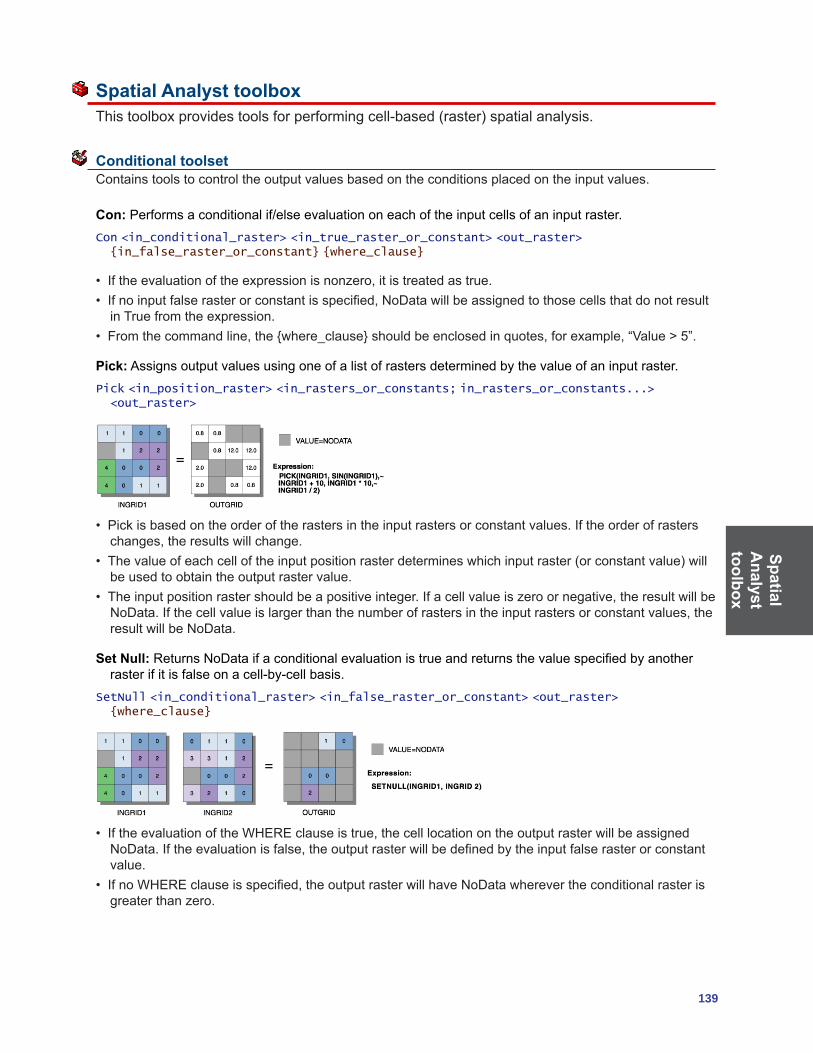
SpatialA
nalysttoolbox
139
Spatial Analyst toolbox Thistoolboxprovidestoolsforperformingcell-based(raster)spatialanalysis.
Conditional toolset Contains tools to control the output values based on the conditions placed on the input values.
Con: Performsaconditionalif/elseevaluationoneachoftheinputcellsofaninputraster.Con <in_conditional_raster> <in_true_raster_or_constant> <out_raster> {in_false_raster_or_constant} {where_clause}
• Iftheevaluationoftheexpressionisnonzero,itistreatedastrue.• Ifnoinputfalserasterorconstantisspecified,NoDatawillbeassignedtothosecellsthatdonotresult
in True from the expression. • Fromthecommandline,the{where_clause}shouldbeenclosedinquotes,forexample,“Value>5”.
Pick: Assigns output values using one of a list of rasters determined by the value of an input raster. Pick <in_position_raster> <in_rasters_or_constants; in_rasters_or_constants...> <out_raster>
• Pickisbasedontheorderoftherastersintheinputrastersorconstantvalues.Iftheorderofrasterschanges,theresultswillchange.
• Thevalueofeachcelloftheinputpositionrasterdetermineswhichinputraster(orconstantvalue)willbe used to obtain the output raster value.
• Theinputpositionrastershouldbeapositiveinteger.Ifacellvalueiszeroornegative,theresultwillbeNoData.Ifthecellvalueislargerthanthenumberofrastersintheinputrastersorconstantvalues,theresult will be NoData.
Set Null: ReturnsNoDataifaconditionalevaluationistrueandreturnsthevaluespecifiedbyanotherraster if it is false on a cell-by-cell basis.
SetNull <in_conditional_raster> <in_false_raster_or_constant> <out_raster> {where_clause}
• IftheevaluationoftheWHEREclauseistrue,thecelllocationontheoutputrasterwillbeassignedNoData.Iftheevaluationisfalse,theoutputrasterwillbedefinedbytheinputfalserasterorconstantvalue.
• IfnoWHEREclauseisspecified,theoutputrasterwillhaveNoDatawherevertheconditionalrasterisgreaterthanzero.

Spat
ial
Ana
lyst
to
olbo
x
140 ArcGIS 9: Geoprocessing Commands Quick Reference Guide
Density toolset Contains tools used to calculate the spread of values over a surface.
Kernel Density: Calculates a magnitude per unit area from point or polyline feature using a kernel functiontofitasmoothlytaperedsurfacetoeachpointorpolyline.
KernelDensity <in_features> <population_field> <out_raster> {cell_size} {search_radius} {SQUARE_MAP_UNITS | SQUARE_MILES | SQUARE_KILOMETERS | ACRES | HECTARES | SQUARE_YARDS | SQUARE_FEET | SQUARE_INCHES | SQUARE_METERS | SQUARE_CENTIMETERS | SQUARE_MILLIMETERS}
• Onlythepointsorportionsofalinethatfallwithintheneighborhoodareconsideredincalculatingthedensity.Ifnopointsorlinesectionsfallwithintheneighborhoodofaparticularcell,thatcellisassignedNoData.
• Largervaluesoftheradiusparameterproduceasmoother,moregeneralizeddensityraster.Smallervalues produce a raster that shows more detail.
• Iftheareaunitscalefactorunitsaresmallrelativetothefeatures(distancebetweenpointsorlengthoflinesections,dependingonfeaturetype),theoutputvaluesmaybesmall.Toobtainlargervalues,selecttheareaunitscalefactorforlargerunits(forexample,squarekilometersversussquaremeters).
Line Density: Calculates a magnitude per unit area from polyline features that fall within a radius around each cell.
LineDensity <in_polyline_features> <population_field> <out_raster> {cell_size} {search_radius} {SQUARE_MAP_UNITS | SQUARE_MILES | SQUARE_KILOMETERS | ACRES | HECTARES | SQUARE_YARDS | SQUARE_FEET | SQUARE_INCHES | SQUARE_METERS | SQUARE_CENTIMETERS | SQUARE_MILLIMETERS}
• Onlytheportionofalinewithintheneighborhoodisconsideredincalculatingthedensity.Ifnolinesfallwithintheneighborhoodataparticularcell,thatcellisassignedNoData.
• Iftheareaunitscalefactorunitsaresmallrelativetothefeatures(lengthoflinesections),theoutputvaluesmaybesmall.Toobtainlargervalues,usetheareaunitscalefactorforlargerunits(forexample,squarekilometersversussquaremeters).
• Largervaluesoftheradiusparameterproduceasmoother,moregeneralizeddensityraster.Smallervalues produce a raster that shows more detail.
Point Density: Calculates a magnitude per unit area from point features that fall within a neighborhood around each cell.
PointDensity <in_point_features> <population_field> <out_raster> {cell_size} {neighborhood} {SQUARE_MAP_UNITS | SQUARE_MILES | SQUARE_KILOMETERS | ACRES | HECTARES | SQUARE_YARDS | SQUARE_FEET | SQUARE_INCHES | SQUARE_METERS | SQUARE_CENTIMETERS | SQUARE_MILLIMETERS}
• Onlythepointsthatfallwithintheneighborhoodareconsideredincalculatingthedensity.Ifnopointsfallwithintheneighborhoodataparticularcell,thatcellisassignedNoData.
• Largervaluesoftheradiusparameterproduceasmoother,moregeneralizeddensityraster.Smallervalues produce a raster that shows more detail.
• Iftheareaunitscalefactorunitsaresmallrelativetothedistancebetweenthepoints,theoutputrastervaluesmaybesmall.Toobtainlargervalues,usetheareaunitscalefactorforlargerunits(forexample,squarekilometersversussquaremeters).

SpatialA
nalysttoolbox
141
Distance toolset Contains tools used to compute distance across a raster dataset with respect to cost or along a path.
Corridor: Calculates the sum of accumulative costs for two input accumulative cost rasters.Corridor <in_distance_raster1> <in_distance_raster2> <out_raster>
• Anytwofloatingpointrasterscanbeusedfortheinput(forexample,anaccumulativecostraster),butboth inputs should be the result of a global cost function.
• Theorderofinputisirrelevant.
Cost Allocation: Calculates for each cell its nearest source based on the least accumulative cost over a cost surface.
CostAllocation <in_source_data> <in_cost_raster> <out_allocation_raster> {maximum_distance} {in_value_raster} {source_field} {out_distance_raster} {out_backlink_raster}
• Whentheinputsourcedataisaraster,thesetofsourcecellsconsistsofallcellsinthesourcerasterthat have valid values. Cells that have NoData values are not included in the source set. The value zeroisconsideredalegitimatesource.AsourcerastermaybeconvenientlycreatedusingtheExtractBytools.
• CelllocationswithNoDataintheinputcostrasteractasbarriersinthecostsurfacefunctions.AnycelllocationthatisassignedNoDataontheinputcostsurfacewillreceiveNoDataonalloutputs(costallocationrasterandoptionallycostdistanceandcostback-linkrasters).
• TheinputvaluerasterisusefuliftheInputsourcedataisarasterandwasderivedfromafunctionoroperatorthatresults;either1orzero.Thesefunctionslosetheoriginalzonevaluesontheinputrasterthat are associated with these locations. The input value raster can either restore these values or allow foranalysisonadditionalcombinationsofzonevalueswithinthesourcelocations.
• TheMaximumdistanceisspecifiedinthesamecostunitsasthoseontheinputcostraster.
Cost Back Link:Definestheneighborthatisthenextcellontheleastaccumulativecostpathtothenearest source.
CostBackLink <in_source_data> <in_cost_raster> <out_backlink_raster> {maximum_distance} {out_distance_raster}
• Whentheinputsourcedataisaraster,thesetofsourcecellsconsistsofallcellsinthesourcerasterthat have valid values. Cells that have NoData values are not included in the source set. The value zeroisconsideredalegitimatesource.AsourcerastermaybeconvenientlycreatedusingtheExtractBytools.
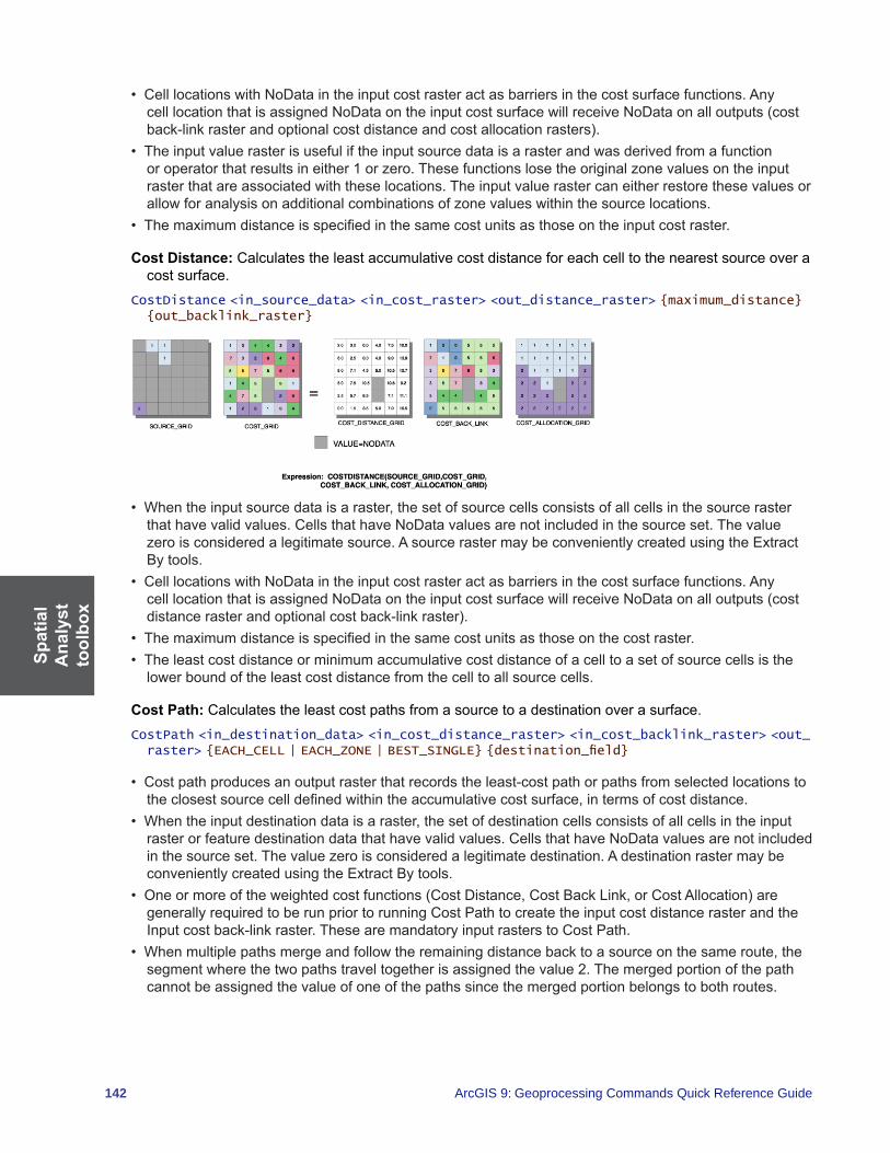
Spat
ial
Ana
lyst
to
olbo
x
142 ArcGIS 9: Geoprocessing Commands Quick Reference Guide
• CelllocationswithNoDataintheinputcostrasteractasbarriersinthecostsurfacefunctions.AnycelllocationthatisassignedNoDataontheinputcostsurfacewillreceiveNoDataonalloutputs(costback-linkrasterandoptionalcostdistanceandcostallocationrasters).
• Theinputvaluerasterisusefuliftheinputsourcedataisarasterandwasderivedfromafunctionoroperatorthatresultsineither1orzero.Thesefunctionslosetheoriginalzonevaluesontheinputraster that are associated with these locations. The input value raster can either restore these values or allowforanalysisonadditionalcombinationsofzonevalueswithinthesourcelocations.
• Themaximumdistanceisspecifiedinthesamecostunitsasthoseontheinputcostraster.
Cost Distance: Calculates the least accumulative cost distance for each cell to the nearest source over a cost surface.
CostDistance <in_source_data> <in_cost_raster> <out_distance_raster> {maximum_distance} {out_backlink_raster}
• Whentheinputsourcedataisaraster,thesetofsourcecellsconsistsofallcellsinthesourcerasterthat have valid values. Cells that have NoData values are not included in the source set. The value zeroisconsideredalegitimatesource.AsourcerastermaybeconvenientlycreatedusingtheExtractBytools.
• CelllocationswithNoDataintheinputcostrasteractasbarriersinthecostsurfacefunctions.AnycelllocationthatisassignedNoDataontheinputcostsurfacewillreceiveNoDataonalloutputs(costdistancerasterandoptionalcostback-linkraster).
• Themaximumdistanceisspecifiedinthesamecostunitsasthoseonthecostraster.• Theleastcostdistanceorminimumaccumulativecostdistanceofacelltoasetofsourcecellsisthe
lower bound of the least cost distance from the cell to all source cells.
Cost Path: Calculates the least cost paths from a source to a destination over a surface.CostPath <in_destination_data> <in_cost_distance_raster> <in_cost_backlink_raster> <out_raster> {EACH_CELL | EACH_ZONE | BEST_SINGLE} {destination_field}
• Costpathproducesanoutputrasterthatrecordstheleast-costpathorpathsfromselectedlocationstotheclosestsourcecelldefinedwithintheaccumulativecostsurface,intermsofcostdistance.
• Whentheinputdestinationdataisaraster,thesetofdestinationcellsconsistsofallcellsintheinputraster or feature destination data that have valid values. Cells that have NoData values are not included inthesourceset.Thevaluezeroisconsideredalegitimatedestination.AdestinationrastermaybeconvenientlycreatedusingtheExtractBytools.
• Oneormoreoftheweightedcostfunctions(CostDistance,CostBackLink,orCostAllocation)aregenerallyrequiredtoberunpriortorunningCostPathtocreatetheinputcostdistancerasterandtheInputcostback-linkraster.ThesearemandatoryinputrasterstoCostPath.
• Whenmultiplepathsmergeandfollowtheremainingdistancebacktoasourceonthesameroute,thesegment where the two paths travel together is assigned the value 2. The merged portion of the path cannot be assigned the value of one of the paths since the merged portion belongs to both routes.
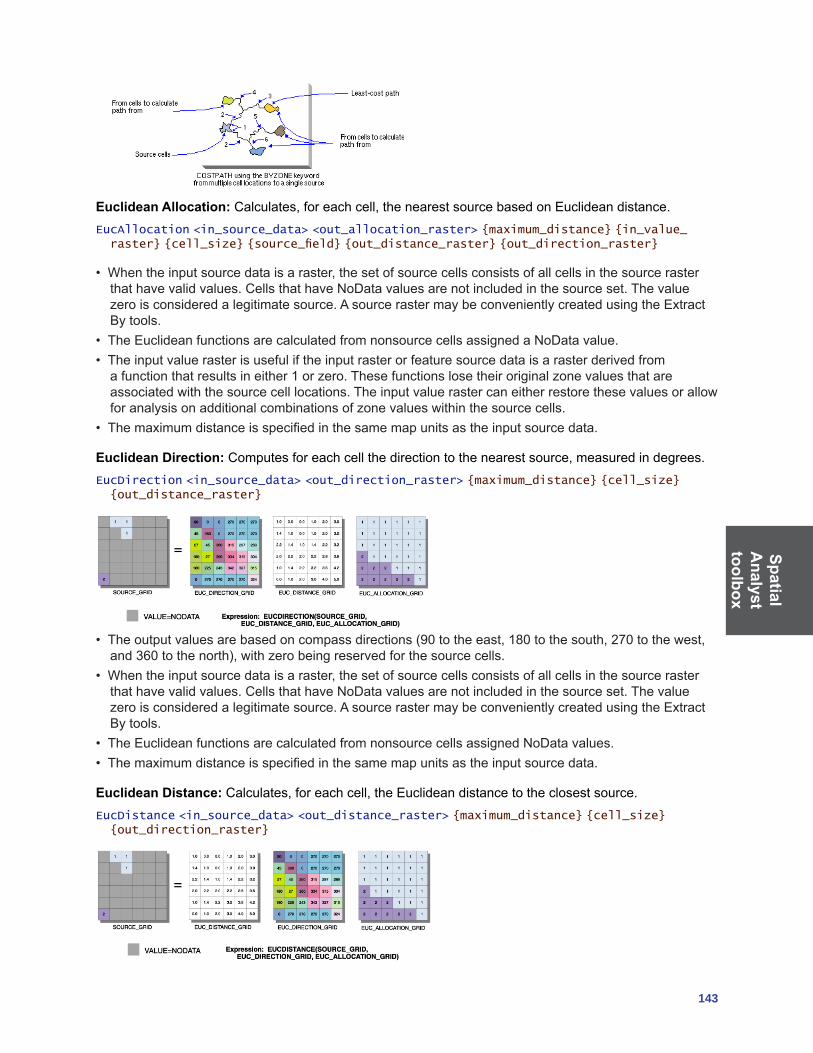
SpatialA
nalysttoolbox
143
Euclidean Allocation:Calculates,foreachcell,thenearestsourcebasedonEuclideandistance.EucAllocation <in_source_data> <out_allocation_raster> {maximum_distance} {in_value_raster} {cell_size} {source_field} {out_distance_raster} {out_direction_raster}
• Whentheinputsourcedataisaraster,thesetofsourcecellsconsistsofallcellsinthesourcerasterthat have valid values. Cells that have NoData values are not included in the source set. The value zeroisconsideredalegitimatesource.AsourcerastermaybeconvenientlycreatedusingtheExtractBytools.
• TheEuclideanfunctionsarecalculatedfromnonsourcecellsassignedaNoDatavalue.• Theinputvaluerasterisusefuliftheinputrasterorfeaturesourcedataisarasterderivedfromafunctionthatresultsineither1orzero.Thesefunctionslosetheiroriginalzonevaluesthatareassociated with the source cell locations. The input value raster can either restore these values or allow foranalysisonadditionalcombinationsofzonevalueswithinthesourcecells.
• Themaximumdistanceisspecifiedinthesamemapunitsastheinputsourcedata.
Euclidean Direction: Computesforeachcellthedirectiontothenearestsource,measuredindegrees.EucDirection <in_source_data> <out_direction_raster> {maximum_distance} {cell_size} {out_distance_raster}
• Theoutputvaluesarebasedoncompassdirections(90totheeast,180tothesouth,270tothewest,and360tothenorth),withzerobeingreservedforthesourcecells.
• Whentheinputsourcedataisaraster,thesetofsourcecellsconsistsofallcellsinthesourcerasterthat have valid values. Cells that have NoData values are not included in the source set. The value zeroisconsideredalegitimatesource.AsourcerastermaybeconvenientlycreatedusingtheExtractBytools.
• TheEuclideanfunctionsarecalculatedfromnonsourcecellsassignedNoDatavalues.• Themaximumdistanceisspecifiedinthesamemapunitsastheinputsourcedata.
Euclidean Distance:Calculates,foreachcell,theEuclideandistancetotheclosestsource.EucDistance <in_source_data> <out_distance_raster> {maximum_distance} {cell_size} {out_direction_raster}

Spat
ial
Ana
lyst
to
olbo
x
144 ArcGIS 9: Geoprocessing Commands Quick Reference Guide
• Whentheinputsourcedataisaraster,thesetofsourcecellsconsistsofallcellsinthesourcerasterthat have valid values. It must be an integer raster. Cells that have NoData values are not included in thesourceset.Thevaluezeroisconsideredalegitimatesource.AsourcerastermaybeconvenientlycreatedusingtheExtractBytools.
• TheEuclideanfunctionsarecalculatedfromnonsourcecellsassignedNoData.• Themaximumdistanceisspecifiedinthesamemapunitsastheinputsourcedata.
Path Distance:Calculates,foreachcell,theleastaccumulativecostdistancetothenearestsource,whileaccountingforsurfacedistanceandhorizontalandverticalcostfactors.
PathDistance <in_source_data> <out_distance_raster> {in_cost_raster} {in_surface_raster} {in_horizontal_raster} {horizontal_factor} {in_vertical_raster} {vertical_factor} {maximum_distance} {out_backlink_raster}
• Whentheinputsourcedataisaraster,thesetofsourcecellsconsistsofallcellsinthesourcerasterthat have valid values. Cells that have NoData values are not included in the source set. The value zeroisconsideredalegitimatesource.AsourcerastermaybeconvenientlycreatedusingtheExtractBytools.
• CellswithNoDataactasbarriersinthePathDistancefunctions.ThecostdistanceforcellsbehindNoData values is calculated by the accumulative cost necessary to move around the NoData barrier. Any cell location that is assigned NoData on any one of the input rasters will receive NoData on all output rasters.
• Themaximumdistanceisspecifiedinthesamecostunitsasthoseontheinputsurfaceraster.• Theleast-cost-pathdistanceorminimumaccumulativecost-distanceofacellfromasetofsource
locations is the lower bound of the least-cost path distance to the cell from all source locations.
Path Distance Allocation: Calculates the nearest source for each cell based on the least accumulative costoveracostsurface,whileaccountingforsurfacedistanceandhorizontalandverticalcostfactors.
PathAllocation <in_source_data> <out_allocation_raster> {in_cost_raster} {in_surface_raster} {in_horizontal_raster} {horizontal_factor} {in_vertical_raster} {vertical_factor} {maximum_distance} {in_value_raster} {source_field} {out_distance_raster} {out_backlink_raster}
• Whentheinputsourcedataisaraster,thesetofsourcecellsconsistsofallcellsinthesourcerasterthat have valid values. Cells that have NoData values are not included in the source set. The value zeroisconsideredalegitimatesource.AsourcerastermaybeconvenientlycreatedusingtheExtractBytools.
• CellswithNoDataactasbarriersinthePathDistancefunctions.ThecostdistanceforcellsbehindNoData values is calculated by the accumulative cost necessary to move around the NoData barrier. Any cell location that is assigned NoData on any one of the input rasters will receive NoData on all output rasters.
• Themaximumdistanceisspecifiedinthesamecostunitsasthoseontheinputsurfaceraster.• Theleast-cost-pathdistanceorminimum-accumulative-costdistanceofacellfromasetofsource
locations is the lower bound of the least-cost-path distance to the cell from all source locations.
Path Distance Back Link:Definestheneighborthatisthenextcellontheleastaccumulativecostpathtothenearestsource,whileaccountingforsurfacedistance,horizontalcostfactors,andverticalcostfactors.
PathBackLink <in_source_data> <out_backlink_raster> {in_cost_raster} {in_surface_raster} {in_horizontal_raster} {horizontal_factor} {in_vertical_raster} {vertical_factor} {maximum_distance} {out_distance_raster}
• Whentheinputsourcedataisaraster,thesetofsourcecellsconsistsofallcellsinthesourcerasterthat have valid values. Cells that have NoData values are not included in the source set. The value zeroisconsideredalegitimatesource.AsourcerastermaybeconvenientlycreatedusingtheExtractBytools.
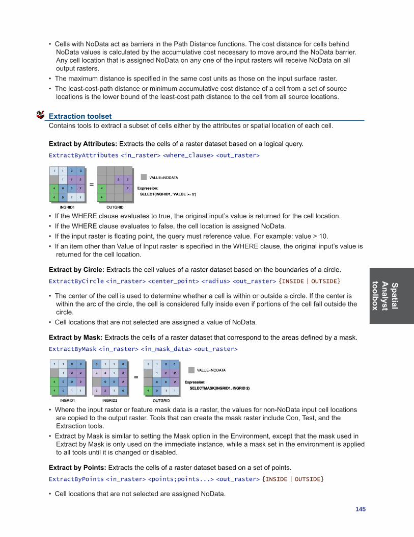
SpatialA
nalysttoolbox
145
• CellswithNoDataactasbarriersinthePathDistancefunctions.ThecostdistanceforcellsbehindNoData values is calculated by the accumulative cost necessary to move around the NoData barrier. Any cell location that is assigned NoData on any one of the input rasters will receive NoData on all output rasters.
• Themaximumdistanceisspecifiedinthesamecostunitsasthoseontheinputsurfaceraster.• Theleast-cost-pathdistanceorminimumaccumulativecostdistanceofacellfromasetofsource
locations is the lower bound of the least-cost path distance to the cell from all source locations.
Extraction toolset Contains tools to extract a subset of cells either by the attributes or spatial location of each cell.
Extract by Attributes:Extractsthecellsofarasterdatasetbasedonalogicalquery.ExtractByAttributes <in_raster> <where_clause> <out_raster>
• IftheWHEREclauseevaluatestotrue,theoriginalinput’svalueisreturnedforthecelllocation.• IftheWHEREclauseevaluatestofalse,thecelllocationisassignedNoData.• Iftheinputrasterisfloatingpoint,thequerymustreferencevalue.Forexample:value>10.• IfanitemotherthanValueofInputrasterisspecifiedintheWHEREclause,theoriginalinput’svalueis
returned for the cell location.
Extract by Circle: Extracts the cell values of a raster dataset based on the boundaries of a circle.ExtractByCircle <in_raster> <center_point> <radius> <out_raster> {INSIDE | OUTSIDE}
• Thecenterofthecellisusedtodeterminewhetheracelliswithinoroutsideacircle.Ifthecenteriswithinthearcofthecircle,thecellisconsideredfullyinsideevenifportionsofthecellfalloutsidethecircle.
• CelllocationsthatarenotselectedareassignedavalueofNoData.
Extract by Mask:Extractsthecellsofarasterdatasetthatcorrespondtotheareasdefinedbyamask.ExtractByMask <in_raster> <in_mask_data> <out_raster>
• Wheretheinputrasterorfeaturemaskdataisaraster,thevaluesfornon-NoDatainputcelllocationsarecopiedtotheoutputraster.ToolsthatcancreatethemaskrasterincludeCon,Test,andtheExtraction tools.
• ExtractbyMaskissimilartosettingtheMaskoptionintheEnvironment,exceptthatthemaskusedinExtractbyMaskisonlyusedontheimmediateinstance,whileamasksetintheenvironmentisappliedto all tools until it is changed or disabled.
Extract by Points: Extracts the cells of a raster dataset based on a set of points.ExtractByPoints <in_raster> <points;points...> <out_raster> {INSIDE | OUTSIDE}
• CelllocationsthatarenotselectedareassignedNoData.

Spat
ial
Ana
lyst
to
olbo
x
146 ArcGIS 9: Geoprocessing Commands Quick Reference Guide
Extract by Polygon: Extracts the cells of a raster dataset based on the boundaries within a polygon feature.
ExtractByPolygon <in_raster> <polygon;polygon...> <out_raster> {INSIDE | OUTSIDE}
• Thecenterofthecellisusedtodeterminewhetheracelliswithinoroutsideapolygon.Ifthecenteriswithinthearcsofthepolygon,thecellisconsideredfullyinsideevenifportionsofthecellfalloutsidethe polygon.
• Thepolygonhasalimitof1,000vertices.Polygonverticesmustbeenteredinclockwiseorder.Thefirstandlastvertexmustbethesametoclosethepolygon.Thearcsofthepolygoncancrossoneanother,but convoluted polygons are not recommended.
• CelllocationsthatarenotselectedareassignedvaluesofNoData.
Extract by Rectangle: Extracts the cells of a raster dataset based on the boundaries of a rectangle.ExtractByRectangle <in_raster> <rectangle> <out_raster> {INSIDE | OUTSIDE}
• Thecenterofthecellisusedtodeterminewhetheracelliswithinoroutsidearectangle.Ifthecenteriswithintheoutlineofarectangle,thecellisconsideredfullyinsideevenifportionsofthecellfalloutsidethe rectangle.
• CelllocationsthatarenotselectedareassignedvaluesofNoData.
Extract Values to Points: Extracts the cell values from a raster at the locations of points in a feature class.
ExtractValuesToPoints <in_point_features> <in_raster> <out_point_features> {NONE | INTERPOLATE} {VALUE_ONLY | ALL}
• Theinterpolationoptiondetermineshowthevalueswillbeobtainedfromtheraster.Thedefaultoptionis to use the value at the center of the cell being sampled. The interpolation option will use bilinear interpolation to interpolate a value for the cell center.
• TheExtractValuestoPointstoolcanbeusedwithafloating-pointinputraster.Inthiscase,theresultingoutputpointdatasetwillonlycontainattributesfromtheinputfeaturedataandthevalueofthecell,asdetermined by the interpolation option.
• TheoutputshapefilewillhaveatleasttheRASTERVALUfieldadded.AllotheritemswillbeappendedaftertheRASTERVALUfield.
• FortheRASTERVALUfieldoftheattributetable,NoDatacellsinthevaluerasterwillbegivenavalueof“-9999”.
Sample:Createsatablethatshowsthevaluesofcellsfromaraster,orsetofrasters,fordefinedlocations.
Sample <in_rasters;in_rasters...> <in_location_data> <out_table> {NEAREST | BILINEAR | CUBIC}
• Thelocationsaredefinedbyrastercellsorbyasetofpoints.• Whentheinputlocationrasterorpointfeaturesarerasters,thesetoflocationcellsconsistsofallcellsintherasterthathaveavalueofzeroorgreater.CellsthathaveNoDatavaluesarenotincludedinthelocationset.AlocationrastermaybeconvenientlycreatedusingtheExtractBytools.
• Iftheinputlocationrasterorpointfeaturesarerasters,NoDatacellswillbelistedintheoutputtableas-9999.

SpatialA
nalysttoolbox
147
Generalization toolset Containstoolstoremoveorreduceerroneousorirrelevantdatawithinarasterthroughaggregation,edgesmoothing,intelligentnoiseremoval,andsoforth.
Aggregate: Generates a reduced resolution raster dataset.Aggregate <in_raster> <out_raster> <cell_factor> {SUM | MAXIMUM | MEAN | MEDIAN | MINIMUM} {EXPAND | TRUNCATE} {DATA | NODATA}
• Thegeoprocessinganalysisenvironment(Extent,CellSize,andMask)isrecognizedbytheAggregatefunction.Todeterminetheoutputraster’sresolutionwhenanintegercellsizehasbeenspecified,multiply the cell resolution of the analysis environment by the input cell factor parameter. If the cell sizefortheanalysisenvironmentissettotheminimumormaximumoftheinputs,theresolutionoftheoutputrasterwillbetheproductoftheinputraster’sresolutionmultipliedbythespecifiedcellfactor.
Boundary Clean:Smoothstheboundarybetweenzonesbyexpandingandshrinkingtheboundary.BoundaryClean <in_raster> <out_raster> {NO_SORT | DESCEND | ASCEND} {TWO_WAY | ONE_WAY}
• Allregionsoflessthanthreecellsinthex-ory-directionwillbechanged.• Inthefirstpass,foranyprocessingcellintheexpandedrasterthathasaneighboroftheoriginalvalueoftheprocessingcell,theoriginalvalueoftheprocessingcellwillberecovered.InthesecondpassofTWO_WAY,anycellintheexpandedrasterthatisnotcompletelysurroundedbyeightcellsofthesamevalue will recover its original value.
• IntheONE_WAYorfirstpassoftheTWO_WAY,cellsofNoDatahavethelowestpriority.InthesecondpassoftheTWO_WAY,cellsofNoDatahavethehighestpriority.
Expand:Expandstheselectedzonesofarasterdatasetbyaspecifiednumberofcells.Expand <in_raster> <out_raster> <number_cells> <zone_values;zone_values...>
• Thezonevaluesmustbeintegers.Theycanbeinanyorder.
Majority Filter: Replaces cell values within a raster dataset based on the majority of their contiguous neighboring cells.
MajorityFilter <in_raster> <out_raster> {FOUR | EIGHT} {MAJORITY | HALF}

Spat
ial
Ana
lyst
to
olbo
x
148 ArcGIS 9: Geoprocessing Commands Quick Reference Guide
• TheuseofFOURwillretainthecornersofrectangularregions.TheuseofEIGHTwillsmooththecorners of rectangular regions.
• ContiguousisdefinedassharinganedgeforakernelofEIGHTandassharingacornerforakernelofFOUR.
• IfthekeywordHALFisspecifiedandtwovaluesoccurasequalhalves,areplacementwillnotoccurifthevalueoftheprocessingcellisthesameasoneofthehalves.HALFallowsmoreextensivefilteringthanMAJORITY.
• Whilethecontiguitycriterionisthesameforedgeandcornerrastercells,theyobeydifferentMAJORITYandHALFrules.UsingakernelofFOUR,anedgeorcornercellalwaysrequirestwomatchingneighborsbeforereplacementwilloccur.WithakernelofEIGHT,acornercellmusthaveallneighborsofthesamevaluebeforeitischanged,whileanedgecellrequiresthreecontiguousneighbors,includingonealongtheedge,beforeanychangewilloccur.
Nibble: Replaces cell values in a raster dataset corresponding to a mask with the values of the nearest neighbors.
Nibble <in_raster> <in_mask_raster> <out_raster> {ALL_VALUES | DATA_ONLY}
• CellsintheinputrastercontainingNoDataarenotnibbled.TonibbleawayNoData,firstconvertittoanother value.
Region Group: Records for each cell of a raster the identity of the connected region to which it belongs. Auniquenumberisassignedtoeachregion.
RegionGroup <in_raster> <out_raster> {FOUR | EIGHT} {WITHIN | CROSS} {ADD_LINK | NO_LINK} {excluded_value}
• Thefirstregionscanned(scanmovesfromlefttoright,toptobottom)receivesthevalue1,thesecond2,andsoforth,untilallregionsareassignedavalue.Thevaluesassignedtotheoutputzonesarebased on when they are encountered in the scanning process. The scanning process cannot be controlled by the user.
• Bydefault,theAddLinkoptionistrue.ThiswillcreateanitemcalledLINKintheattributetableoftheoutputraster,whichretainstheoriginalvalueforeachcellfromtheinputraster.
Shrink:Shrinkstheselectedzonesbyaspecifiednumberofcells.Shrink <in_raster> <out_raster> <number_cells> <zone_values;zone_values...>

SpatialA
nalysttoolbox
149
• Whentwoadjacentregionsarepartoftheselectedsettoshrink,thereisnochangeattheboundarybetween them.
• NoDatahasthesamepriorityasanyvalidvaluetoinvadeareasvacatedbyshrinkingselectedvalues.Therefore,ifaselectedvalueisadjacenttoNoData,itmaybecomeNoDataaftershrinking.
Thin: Thinsrasterizedlinearfeaturesinarasterdatasetbyreducingthenumberofcellsrepresentingthewidth of the features.
Thin <in_raster> <out_raster> {ZERO | NODATA} {NO_FILTER | FILTER} {ROUND | SHARP} {maximum_thickness}
• TheFILTERoptionusesthesamefilteringalgorithmasBoundaryCleantoremoveshortlinearfeaturesextending from the major branch. It may also remove features narrower than three cells.
• Specifyingthemaximumthicknessofinputlinearfeaturesisessentialforthinningrasterswherethethickness of linear features may exceed or stay well below the default maximum thickness value. Thebestresultscanbeexpectedwhenthemaximumthicknessfitsthethickestlinearfeaturestobethinned.
Groundwater toolset Contains tools used to measure hydrodynamic movement within or along a surface.
Darcy Flow:Calculatesthegroundwatervolumebalanceresidualandotheroutputsforsteadyflowinanaquifer.
DarcyFlow <in_head_raster> <in_porosity_raster> <in_thickness_raster> <in_transmissivity_raster> <out_volume_raster> {out_direction_raster} {out_magnitude_raster}
• TheonlydifferencesbetweenDarcyFlowandDarcyVelocityare:• DarcyFlowproducesanoutputvolumeraster.DarcyVelocitydoesnot.• DarcyVelocityoutputsonlydirectionandmagnituderastersasrequiredoutput.DarcyFlow
produces these outputs optionally.• Thedirectionofthevelocityvectorisrecordedincompasscoordinates(degreesclockwisefromnorth),
the magnitude in units of length over time.• Noparticularsystemofunitsisspecifiedbythisfunction.Alldatashouldbeconsistent,usingthesameunitfortime(seconds,days,years)andlength(feet,meters)foralldata.
• Howevertheheadelevationrasterisobtained,theheadmustbeconsistentwiththetransmissivityraster.Thatis,theheadmustreflecttheflowthroughthetransmissivityfield.Itisnotsufficienttousevaluesobtainedbymeasurementandtestinginthefield—thegriddedvaluesmustbeanalyzedforconsistencywiththeaidofaproperporousmediumflowprogram.Consistencyimpliesthattheheadswouldactuallybeproducedbythemodeledtransmissivityfield.Sincethetrueandmodeledtransmissivityfieldsoftendifferinpractice,thetrueandmodeledheadfieldsdifferaswell.ChecktheheadsforconsistencybyexaminingtheresidualrasterproducedbyDarcyFlow.Theresidualwillreflecttheconsistencyofthedataset.AnyanalysisusingDarcyFlowoninconsistentdatasetswillproduce meaningless results.

Spat
ial
Ana
lyst
to
olbo
x
150 ArcGIS 9: Geoprocessing Commands Quick Reference Guide
• Theeffectiveporosityfield,aphysicalpropertyoftheaquifer,willgenerallybeestimatedfromgeologicaldata.Itisdefinedasthevolumeofvoidspacethatcontributestofluidflowdividedbytheentirevolume.Porosityisexpressedasanumberbetweenzeroand1,withtypicalvaluesaround0.35,andisdimensionless.Avalueofeffectiveporosityof0.35meansthat35percentofthevolumeoftheporousmediumcontributestofluidflow.Theremaining65percent,consistingofsolidmatrixandunconnectedpores,doesnotcontributetofluidflow.
• Thesaturatedthickness,measuredinunitsoflength,isinterpretedfromgeologicalinformation.Foraconfinedaquifer,thismeasureisthethicknessoftheformationbetweentheupperandlowerconfininglayers.Foranunconfinedaquifer,thesaturatedthicknessisthedistancebetweenthewatertableandthelowerconfininglayer.
Darcy Velocity: Calculatesthegroundwaterseepagevelocityvector(directionandmagnitude)forsteadyflowinanaquifer.
DarcyVelocity <in_head_raster> <in_porosity_raster> <in_thickness_raster> <in_transmissivity_raster> <out_direction_raster> <out_magnitude_raster>
• TheonlydifferencesbetweenDarcyFlowandDarcyVelocityare:• DarcyFlowproducesanoutputvolumeraster.DarcyVelocitydoesnot.• DarcyVelocityoutputsonlydirectionandmagnituderastersasrequiredoutput.DarcyFlow
produces these outputs optionally.• Thedirectionofthevelocityvectorisrecordedincompasscoordinates(degreesclockwisefromnorth),
the magnitude in units of length over time.• Noparticularsystemofunitsisspecifiedbythisfunction.Alldatashouldbeconsistent,usingthesameunitfortime(seconds,days,years)andlength(feet,meters)foralldata.
• Howevertheheadelevationrasterisobtained,theheadmustbeconsistentwiththetransmissivityraster.Thatis,theheadmustreflecttheflowthroughthetransmissivityfield.Itisnotsufficienttousevaluesobtainedbymeasurementandtestinginthefield—therasterizedvaluesmustbeanalyzedforconsistencywiththeaidofaproperporousmediumflowprogram.Consistencyimpliesthattheheadswouldactuallybeproducedbythemodeledtransmissivityfield.Sincethetrueandmodeledtransmissivityfieldsoftendifferinpractice,thetrueandmodeledheadfieldsdifferaswell.ChecktheheadsforconsistencybyexaminingtheresidualrasterproducedbyDarcyFlow.Theresidualwillreflecttheconsistencyofthedataset.AnyanalysisusingDarcyVelocityoninconsistentdatasetswillproduce meaningless results.
• Theeffectiveporosityfield,aphysicalpropertyoftheaquifer,willgenerallybeestimatedfromgeologicaldata.Itisdefinedasthevolumeofvoidspacethatcontributestofluidflowdividedbytheentirevolume.Porosityisexpressedasanumberbetweenzeroand1,withtypicalvaluesaround0.35,andisdimensionless.Avalueofeffectiveporosityof0.35meansthat35percentofthevolumeoftheporousmediumcontributestofluidflow.Theremaining65percent,consistingofsolidmatrixandunconnectedpores,doesnotcontributetofluidflow.
• Thesaturatedthickness,measuredinunitsoflength,isinterpretedfromgeologicalinformation.Foraconfinedaquifer,thismeasureisthethicknessoftheformationbetweentheupperandlowerconfininglayers.Foranunconfinedaquifer,thesaturatedthicknessisthedistancebetweenthewatertableandthelowerconfininglayer.
Particle Track:Calculatesthepathofaparticlethroughavelocityfield,returninganASCIIfileofparticletrackingdataand,optionally,acoverageoftrackinformation.
ParticleTrack <in_direction_raster> <in_magnitude_raster> <source_point> <out_track_file> {step_length} {tracking_time} {out_track_polyline_features}
• TheinputdirectionandmagnituderastersshouldbefromthesamerunofDarcyFlow.• ThepathfilegeneratedbythisfunctionisanASCIItextfilecontaininginformationaboutposition,localvelocitydirectionandmagnitude,andcumulativelengthandtimeoftravelalongthepath.ThisfileisusedforinputbyPorousPuff.Theformatofthisfileisasfollows:

SpatialA
nalysttoolbox
151
Time X Y Length Flow direction Flow magnitude0.000000000 0.000000000 482.8400000 0.000000000 90.00000000 0.04418909563
113.1648712 4.999804443 482.7957786 5.000000000 91.01366126 0.04418332249
226.2741353 9.998043277 482.6630814 10.00000000 92.02765240 0.04421519432
339.3574334 14.99315255 482.4419855 15.00000000 93.04094157 0.04421519432
452.3447720 19.98356700 482.1325285 20.00000000 94.05521317 0.04425274599
565.2657591 24.96772671 481.7348453 25.00000000 95.06807622 0.04427874865
678.0514031 29.94406931 481.2490323 30.00000000 96.08254679 0.04433188322
790.7309576 34.91104149 480.6752838 35.00000000 97.09488082 0.04437362239
• NoparticularsystemofunitsisspecifiedbyParticleTrack.Itisimportantthatalldatasuppliedbeinaconsistentsetofunits,usingthesameunitfortime(seconds,days,years)andlength(feet,meters)forall data.
• ThetwooutputsfromParticleTrackare(1)aparticletrackASCIIfileusingthenamespecifiedasoutputparticletrackfileand(2)apolylinefeatureclass(optional).
Porous Puff:Calculatesthetime-dependent,two-dimensionalconcentrationdistributioninmasspervolumeofasoluteintroducedinstantaneouslyandatadiscretepointintoaverticallymixedaquifer.
PorousPuff <in_track_file> <in_porosity_raster> <in_thickness_raster> <out_raster> <mass> {dispersion_time} {longitudinal_dispersivity} {dispersivity_ratio} {retardation_factor} {decay_coefficient}
• Noparticularsystemofunitsisspecifiedbythisfunction.Itisimportantthatalldatasuppliedbeconsistent,thatis,usingthesameunitfortime(seconds,days,years),length(feet,meters),andmass(kilograms,slugs)foralldata.
• Theeffectiveporosityfield,aphysicalpropertyoftheaquifer,willgenerallybeestimatedfromgeologicaldata.Itisdefinedasthevolumeofvoidspacethatcontributestofluidflowdividedbytheentirevolume.Porosityisexpressedasanumberbetween0.0and1.0,withtypicalvaluesaround0.35,andisdimensionless.Avalueofeffectiveporosityof0.35meansthat35percentofthevolumeoftheporousmediumcontributestofluidflow.Theremaining65percent,consistingofsolidmatrixandunconnectedpores,doesnotcontributetofluidflow.
• Thesaturatedthickness,measuredinunitsoflength,isinterpretedfromgeologicalinformation.Foraconfinedaquifer,thismeasureisthethicknessoftheformationbetweentheupperandlowerconfininglayers.Foranunconfinedaquifer,thesaturatedthicknessisthedistancebetweenthewatertableandthelowerconfininglayer.
• Thedecaycoefficientλisrelatedtothehalf-lifeT½as:
Forexample,thehalf-lifeofcarbon-14is5,730years,soitsdecaycoefficientisln2=0.693.Sotheequationbecomes0.693/5730=1.21x10-4/year.Astableconstituenthasadecaycoefficientofzero,correspondingtoaninfinitehalf-life.Half-livesofradioisotopesareavailablefromseveralsources,includingtheCRCHandbookofChemistryandPhysics.
Hydrology toolset Containstoolsprovidinghydrologyfunctionstosimulatetheflowofwateroveranelevationsurfaceandcreates either a stream network or a watershed.
Basin: Creates a raster dataset delineating all drainage basins.Basin <in_flow_direction_raster> <out_raster>
• BestresultswillbeobtainedfromBasiniftheFORCEoptionwasusedwhencreatingtheFlowDirection raster.

Spat
ial
Ana
lyst
to
olbo
x
152 ArcGIS 9: Geoprocessing Commands Quick Reference Guide
• Allcellsintherasterwillbelongtoabasin,evenifthatbasinisonlyonecell.
Fill:Fillssinksinasurfacerastertoremovesmallimperfectionsinthedata.Fill <in_surface_raster> <out_surface_raster> {z_limit}
• Asinkisacellwithanundefineddrainagedirection;nocellssurroundingitarelower.Thepourpointistheboundarycellwiththelowestelevationforthecontributingareaofasink.Ifthesinkwerefilledwithwater,thisisthepointwherewaterwouldpourout.
• Allsinksthatarelessthanthez-limitlowerthantheirlowestadjacentneighborwillbefilledtotheheightof their pour points.
• TheSinktoolcanbeusedtofindthenumberofsinksandhelpidentifytheirdepth.Knowingthedepthofthesinkscanhelpindetermininganappropriatez-limitforFill.
• Fillcanalsobeusedtoremovepeaks.Apeakisacellwherenoadjacentcellsarehigher.Toremovepeaks,theinputsurfacerastermustbeinverted.
Flow Accumulation:Createsarasterdatasetofaccumulatedflowtoeachcell.FlowAccumulation <in_flow_direction_raster> <out_accumulation_raster> {in_weight_raster} {FLOAT | INTEGER}
• TheresultofFlowAccumulationisarasterofaccumulatedflowtoeachcell,asdeterminedbyaccumulatingtheweightforallcellsthatflowintoeachdownslopecell.
• Theaccumulatedflowisbasedonthenumberofcellsflowingintoeachcellintheoutputraster.Thecurrent processing cell is not considered in this accumulation.
• Outputcellswithahighflowaccumulationareareasofconcentratedflowandmaybeusedtoidentifystream channels.
• Outputcellswithaflowaccumulationofzeroarelocaltopographichighsandmaybeusedtoidentifyridges.
Flow Direction:Createsarasterdatasetofflowdirectionfromeachcelltoitssteepestdownslopeneighbor.
FlowDirection <in_surface_raster> <out_flow_direction_raster> {NORMAL | FORCE} {out_drop_raster}
• TheoutputoftheFlowDirectiontoolisanintegerrasterwhosevaluesrangefrom1to255.Thevaluesfor each direction from the center are:
Forexample,ifthedirectionofthesteepestdropwastotheleftofthecurrentprocessingcell,itsflowdirectionwouldbecodedas16.
• Ifacellislowerthanitseightneighbors,thatcellisgiventhevalueofitslowestneighbor,andflowisdefinedtowardthiscell.
SpatialA
nalysttoolbox
153
• Ifacellhasthesamechangeinz-valueinmultipledirectionsandthatcellispartofasink,theflowdirectionisreferredtoasundefined.Insuchcases,thevalueforthatcellintheoutputflowdirectionraster will be the sum of those directions.
Flow Length:Calculatesdistanceorweighteddistancealongaflowpath.FlowLength <in_flow_direction_raster> <out_raster> {DOWNSTREAM | UPSTREAM} {in_weight_raster}
• Thevaluetypeforthe<out_raster>isfloatingpoint.
Sink: Creates a raster dataset identifying all sinks or areas of internal drainage.Sink <in_flow_direction_raster> <out_raster>
• TheoutputoftheSinkfunctionisanintegerrasterwitheachsinkbeingassignedauniquevalue.Sinksare numbered between 1 and the number of sinks.
Snap Pour Point: Snapspourpointstothecellofhighestflowaccumulationwithinaspecifieddistance.SnapPourPoint <in_pour_point_data> <in_accumulation_raster> <out_raster> <snap_distance> {pour_point_field}
• TheSnapPourPointtoolisusedtoensuretheselectionofpointsofhigh-accumulatedflowwhendelineatingdrainagebasinsusingtheWatershedtool.SnapPourPointwillsearchwithinasnapdistancearoundthespecifiedpourpointsforthecellofhighestaccumulatedflowandmovethepourpoint to that location.
• Theoutputisanintegerrasterwheretheoriginalpourpointlocationshavebeensnappedtolocationsofhigheraccumulatedflow.
Stream Link: Assignsuniquevaluestosectionsofarasterlinearnetworkbetweenintersections.StreamLink <in_stream_raster> <in_flow_direction_raster> <out_raster>
• TheinputstreamrastercanbecreatedbythresholdingtheresultsofFlowAccumulation.• Thestreamrasterlinearnetworkshouldberepresentedasvaluesgreaterthanorequalto1ona
background of NoData.
Stream Order: Assigns a numeric order to segments of a raster dataset representing branches of a linear network.
StreamOrder <in_stream_raster> <in_flow_direction_raster> <out_raster> {STRAHLER | SHREVE}
• Theinputstreamrasterlinearnetworkshouldberepresentedasvaluesgreaterthanorequaltooneona background of NoData.
• TheresultsofFlowAccumulationcanbeusedtocreatearasterstreamnetworkbyapplyingathresholdvaluetoselectcellswithahighaccumulatedflow.Forexample,thecellsthathavemorethan100cellsflowingintothemareusedtodefinethestreamnetwork.UseConorSetNulltocreateastreamnetworkrasterwhereflowaccumulationvaluesof100orgreatergoto1,andtheremainderareputtothebackground(NoData).TheresultingstreamnetworkcanbeusedinStreamLinkandStreamToFeature.
• IntheSTRAHLERordermethod,alllinkswithnotributariesareassignedanorderof1andarereferredtoasfirstorder.Whentwofirst-orderlinksintersect,thedownslopelinkisassignedanorderof2.Whentwosecond-orderlinksintersect,thedownslopelinkisassignedanorderof3,andsoon.Onlywhen two links of the same order intersect will the order increase. This is the most common method of ordering.

Spat
ial
Ana
lyst
to
olbo
x
154 ArcGIS 9: Geoprocessing Commands Quick Reference Guide
TheoutputfromtheStreamOrdertoolisanintegerraster.
Stream to Feature: Converts a raster dataset representing a linear network to features representing the linear network.
StreamToFeature <in_stream_raster> <in_flow_direction_raster> <out_polyline_features> {SIMPLIFY| NO_SIMPLIFY}
• Theinputstreamrasterlinearnetworkshouldberepresentedasvaluesgreaterthanorequalto1onabackground of NoData.
• TheresultsofFlowAccumulationcanbeusedtocreatearasterstreamnetworkbyapplyingathresholdvaluetoselectcellswithahighaccumulatedflow.Forexample,thecellsthathavemorethan100cellsflowingintothemareusedtodefinethestreamnetwork.UseConorSetNulltocreateastreamnetworkrasterwhereFlowAccumulationvaluesof100orgreatergoto1,andtheremainderareputtothebackground(NoData).TheresultingstreamnetworkcanbeusedinStreamLinkandStreamToFeature.
• Thereshouldbecontiguousfeatureswiththesamevalue,suchastheresultsofStreamOrderorStreamLink.StreamToFeatureshouldnotbeusedonarasterwheretherearefewadjacentcellsofthe same value.
• Thearcsoftheoutputshapefilewillpointdownstream.
Watershed: Determines the contributing area above a set of cells in a raster dataset.Watershed <in_flow_direction_raster> <in_pour_point_data> <out_raster> {pour_point_field}
• Thevalueofeachwatershedwillbetakenfromthevalueofthesourceintheinputrasterorfeaturepourpointdata.Whenthepourpointisarasterdataset,thecellvalueswillbeused.Whenthepourpointisapointfeaturedataset,thevalueswillcomefromthespecifiedfield.
• BetterresultswillbeobtainediftheSnapPourPointtoolisusedbeforehandtohelplocatethepourpointstocellsofhigh-accumulatedflow.
Interpolation toolset Contains tools to create a raster surface from point features.
IDW:Interpolatesasurfacefrompointsusinganinversedistanceweightedtechnique.IDW <in_point_features> <z_field> <out_raster> {cell_size} {power} {search_radius} {in_barrier_polyline_features}
• Thebarriersoptionisusedtospecifythelocationoflinearfeaturesknowntointerruptthesurfacecontinuity.Thesefeaturesdonothavez-values.Cliffs,faults,orembankmentsaretypicalexamplesofbarriers.Barrierslimittheselectedsetoftheinputsamplepointsusedtointerpolateoutputz-valuestothose samples on the same side of the barrier as the current processing cell.
• TheoutputvalueforacellusingIDWislimitedtotherangeofthevaluesusedtointerpolate.BecauseIDWisaweighteddistanceaverage,theaveragecannotbegreaterthanthehighestorlessthanthelowestinput.Therefore,itcannotcreateridgesorvalleysiftheseextremeshavenotalreadybeensampled(WatsonandPhilip1985).
• ThebestresultsfromIDWareobtainedwhensamplingissufficientlydensewithregardtothelocalvariationyouareattemptingtosimulate.Ifthesamplingofinputpointsissparseoruneven,theresultsmaynotsufficientlyrepresentthedesiredsurface(WatsonandPhilip1985).

SpatialA
nalysttoolbox
155
Kriging: Interpolates a raster dataset from a set of points using kriging.Kriging <in_point_features> <z_field> <out_surface_raster> <semiVariogram_props> {cell_size} {search_radius} {out_variance_prediction_raster}
• Theuniversalkrigingtypes(linearwithlineardriftandlinearwithquadraticdrift)assumethatthereisastructural component present and that the local trend varies from one location to another.
• TheadvancedparametersallowcontrolofthesemivariogramusedforKriging.Adefaultvalueforlagsizeisinitiallysettothedefaultoutputcellsize.Formajorrange,partialsill,andnugget,adefaultvaluewillbecalculatedinternallyifnothingisspecified.
• Lowvalueswithintheoutputvarianceofpredictionrasterindicateahighdegreeofconfidenceinthepredictedvalue.Highvaluesmayindicateaneedformoredatapoints.
Natural Neighbor:Interpolatesasurfacefrompointsusinganaturalneighbortechnique.NaturalNeighbor <in_point_features> <z_field> <out_raster> {cell_size}
• TheNaturalNeighbortoolcanefficientlyhandlelargenumbersofinputpoints.Otherinterpolatorsmayhavedifficultywithlargepointdatasets.
Spline:Interpolatesasurfacefrompointsusingaminimumcurvaturesplinetechnique.Spline <in_point_features> <z_field> <out_raster> {cell_size} {REGULARIZED | TENSION} {weight} {number_points}
• TheresultingsmoothsurfacefromSplinepassesexactlythroughtheinputpoints.• TheREGULARIZEDoptionofSplineusuallyproducessmoothersurfacesthanthosecreatedwiththeTENSIONoption.
• FortheREGULARIZEDoption,highervaluesusedfortheWeightparameterproducesmoothersurfaces.Thevaluesenteredforthisparametermustbeequaltoorgreaterthanzero.Typicalvaluesthatareusedare0,0.001,0.01,0.1,and0.5.TheWeightisthesquareoftheparameter,referredtointheliteratureastau(t).
• FortheTENSIONoption,highervaluesenteredfortheWeightparameterresultinsomewhatcoarsersurfaces but with surfaces that closely conform to the control points. The values entered have to beequaltoorgreaterthanzero.Typicalvaluesare0,1,5,and10.TheWeightisthesquareoftheparameter,referredtointheliteratureasphi(Φ).
• ThegreaterthevalueofNumberofPoints,thesmootherthesurfaceoftheoutputraster.
Spline with Barriers:Interpolatesasurface,usingbarriers,frompointsusingaminimumcurvaturesplinetechnique.Thebarriersareenteredaseitherpolygonorpolylinefeatures.
SplineWithBarriers <input_point_features> <z_value_field> {input_barrier_features} <output_cell_size> <output_raster> {smoothing_factor}
Topo to Raster:Interpolatesahydrologicallycorrectsurfacefrompoint,line,andpolygondata.TopoToRaster <feature_layer{Field} {Type};feature_layer{Field} {Type}...> <out_surface_raster> {cell_size} {extent} {Margin} {minimum_z_value} {maximum_z_value} {ENFORCE | NO_ENFORCE | ENFORCE_WITH_SINK} {CONTOUR | SPOT} {maximum_iterations} {roughness_penalty} {discrete_error_factor} {vertical_standard_error} {tolerance_1} {tolerance_2} {out_stream_features} {out_sink_features} {out_diagnostic_file} {out_parameter_file}
• TopotoRasterwillonlyusefourinputdatapointsfortheinterpolationofeachoutputcell.Alladditionalpointsareignored.Iftoomanypointsareencounteredbythealgorithm,anerrormayoccurindicating the point dataset has too many points. The maximum number of points that can be used isnrows*ncols,wherenrowsisthenumberofrowsintheoutputrasterandncolsisthenumberofcolumns.

Spat
ial
Ana
lyst
to
olbo
x
156 ArcGIS 9: Geoprocessing Commands Quick Reference Guide
• Streamdataalwaystakespriorityoverpointorcontourdata;therefore,elevationdatapointsthatconflictwithdescentdowneachstreamareignored.Streamdataisapowerfulwayofaddingtopographicinformationtotheinterpolation,furtherensuringthequalityoftheoutputDEM.
• SometypicalvaluesfortheTolerance1andTolerance2settingsare:• Forpointdataat1:100,000scale,use5.0and200.0.• Forlessdensepointdataatupto1:500,000scale,use10.0and400.0.• Forcontourdatawithcontourspacingof10,use5.0and100.0.
Topo to Raster by File:Interpolatesahydrologicallycorrectsurfacefrompoint,line,andpolygondatausingparametersspecifiedinafile.
TopoToRasterByFile <in_parameter_file> <out_surface raster> {out_stream_features} {out_sink_features}
• Theparameterfileisstructuredwiththeinputdatasetslistedfirst,followedbythevariousparametersettings,thentheoutputoptions.
Theinputdataidentifiestheinputdatasetsand,whereapplicable,fields.Therearesixtypesofinput:Contours,Points,Sinks,Streams,Lakes,andBoundaries.Asmanyinputscanbeusedasdesired,within reason. The order in which the inputs are entered does not have any bearing on the outcome. <Path>indicatesapathtoadataset,<Item>indicatesafieldname,and<#>indicatesavaluetobeentered.• Contours—Contourlinedatasetwithitemcontainingheightvalues.• Points—Pointdatasetwithitemcontainingheightvalues.• Sinks—Pointdatasetcontainingsinklocations.Ifthedatasethaselevationvaluesforthesinks,specifythatfieldnameasthe<Item>.Ifonlythelocationsofthesinksaretobeused,useNONEfor<Item>.
• Streams—Streamlinedataset.Heightvaluesarenotnecessary.• Lakes—Lakepolygondataset.Heightvaluesarenotnecessary.• Boundary—Boundarypolygondataset.Heightvaluesarenotnecessary.• Enforce—Controlswhetherdrainageenforcementisapplied.• Datatype—Primarytypeofinputdata.• Iterations—Themaximumnumberofiterationsthealgorithmperforms.• RoughnessPenalty—Themeasureofsurfaceroughness.• DiscretizationErrorFactor—Theamounttoadjustthedatasmoothingoftheinputdataintoaraster.• VerticalStandardError—Theamountofrandomerrorinthez-valuesoftheinputdata.• Tolerances—Thefirstreflectstheaccuracyofelevationdatainrelationtosurfacedrainage,andthe
other prevents drainage clearance through unrealistically high barriers.• Z-Limits—Lowerandupperheightlimits.• Extent—Minimumx,minimumy,maximumx,andmaximumycoordinatelimits.• CellSize—Theresolutionofthefinaloutputraster.• Margin—Distanceincellstointerpolatebeyondthespecifiedoutputextentandboundary.• OutputStreamFeatures—OnlyuseifOutputstreampolylinefeaturesissetintheTopotoRasterbyFiledialogbox.
• OutputSinkFeatures—OnlyuseifOutputremainingsinkpointfeaturesissetintheTopotoRasterbyFiledialogbox.
• OutputDiagnosticsFile—Thelocationandnameofthediagnosticsfile.• Anexampleparameterfileis:
Contour D:\data\contours2\arc HEIGHT
Point D:\data\points2\point SPOTS
Sink D:\data\sinks_200.shp
Stream D:\data\streams\arc
Lake D:\data\lakes\polygon

SpatialA
nalysttoolbox
157
Boundary D:\data\clipcov\polygon
ENFORCE ON
DATATYPE CONTOUR
ITERATIONS 40
ROUGHNESS_PENALTY 0.00000000000
DISCRETE_ERROR_FACTOR 1.00000000000
VERTICAL_STANDARD_ERROR 0.00000000000
TOLERANCES 2.50000000000 100.00000000000
ZLIMITS -2000.00000000000 13000.00000000000
EXTENT -810480.62500000000 8321785.00000000000 810480.62500000000 10140379.00000000000
CELL_SIZE 1800.00000000000
MARGIN 20
OUT_STREAM
OUT_SINK
OUT_DIAGNOSTICS D:\data\ttr_diag.txt
Trend: Interpolatesasurfacefrompointsusingatrendtechnique.Trend <in_point_features> <z_field> <out_raster> {cell_size} {order} {LINEAR | LOGISTIC} {out_rms_file}
• Astheorderofthepolynomialisincreased,thesurfacebeingfittedbecomesprogressivelymorecomplex. A higher-order polynomial will not always generate the most accurate surface; it is dependent on the data.
• Theoptionalrootmeansquare(RMS)fileoutputcontainsinformationontheRMSerroroftheinterpolation. This information can be used to determine the best value to use for the polynomial order by changing the order value until you get the lowest RMS error.
• FortheLOGISTICoptionofTypeofRegression,theZvaluefieldofinputpointfeaturesshouldhavecodesofzeroand1.
Local toolset Contains tools to compute an output raster dataset where the output value at each location is a function of the value associated with that location on one or more raster datasets.
Cell Statistics: Calculates a per-cell statistic from multiple raster datasets.CellStatistics <in_rasters_or_constants;in_rasters_or_constants...> <out_raster> {MEAN | MAJORITY | MAXIMUM | MEDIAN | MINIMUM | MINORITY | RANGE | STD | SUM | VARIETY}
• Theorderofinputrastersisirrelevant.
Combine:Combinesmultiplerasterssoauniqueoutputvalueisassignedtoeachuniquecombinationofinput values.
Combine <in_rasters;in_rasters...> <out_raster>

Spat
ial
Ana
lyst
to
olbo
x
158 ArcGIS 9: Geoprocessing Commands Quick Reference Guide
• CombineissimilartoCombinatorialOr.Theybothassignanewnumbertoeachuniquecombinationofinput values.
• Combineworksonintegervaluesandtheirassociatedattributetables.Ifthevaluesontheinputarefloatingpoint,theywillbeautomaticallytruncated,testedforuniquenesswiththeotherinput,andsentto the output attribute table.
• Nomorethan20rasterscanbeusedasinputtoCombine.
Equal to Frequency:Evaluatesthenumberoftimestheinputrasterdatasetvaluesareequaltoaspecifiedvalueonacell-by-cellbasis.
EqualToFrequency <in_value_raster> <in_rasters;in_rasters...> <out_raster>
• Anarbitrarynumberofrasterscanbespecifiedintheinputrasterslist.
Greater Than Frequency: Evaluates the number of times the input raster dataset values are greater than aspecifiedvalueonacell-by-cellbasis.
GreaterThanFrequency <in_value_raster> <in_rasters;in_rasters...> <out_raster>
• Anarbitrarynumberofrasterscanbespecifiedintheinputrasterslist.
Highest Position: Determines the position of a raster dataset with the maximum value in a set of raster datasets.
HighestPosition <in_rasters_or_constants;in_rasters_or_constants...> <out_raster>
• Anarbitrarynumberofrasterscanbespecifiedintheinputrasterslist.• TheorderofinputsisrelevantfortheHighestPositiontool.• Iftwoormoreinputrasterscontainthemaximumvalueforaparticularcelllocation,thepositionofthefirstoneisreturnedontheoutputraster.
Less Than Frequency: Evaluates the number of times the input raster dataset values are less than a specifiedvalueonacell-by-cellbasis.
LessThanFrequency <in_value_raster> <in_rasters;in_rasters...> <out_raster>

SpatialA
nalysttoolbox
159
• Anarbitrarynumberofrasterscanbespecifiedintheinputrasterslist.
Lowest Position: Determines the position of a raster with the minimum value in a set of rasters.LowestPosition <in_rasters_or_constants;in_rasters_or_constants...> <out_raster>
• Anarbitrarynumberofrasterscanbespecifiedintheinputrasterslist.• TheorderofinputsisrelevantfortheLowestPositiontool.• Iftwoormoreinputrasterscontaintheminimumvalueforaparticularcelllocation,thepositionofthefirstoneencounteredisreturnedontheoutputraster.
Popularity:Determinesthevaluethatisataspecifiedlevelofpopularityonacell-by-cellbasis.Popularity <in_popularity_raster_or_constant> <in_rasters;in_rasters...> <out_raster>
• Anarbitrarynumberofrasterscanbespecifiedintheinputrasterslist.• Theorderofinputrastersisirrelevant.
Rank:Returnsthevalueofasetofrastersbasedonaranklevelspecifiedbyanotherraster.Rank <in_rank_raster_or_constant> <in_rasters;in_rasters...> <out_raster>
• Anarbitrarynumberofrasterscanbespecifiedintheinputrasterslist.• Theorderofinputrastersisirrelevant.• Iftheinputvaluesareallthesameforanycelllocation,nomatterwhatthespecifiedpopularityis,the
output value will be the same as the input for that cell location.
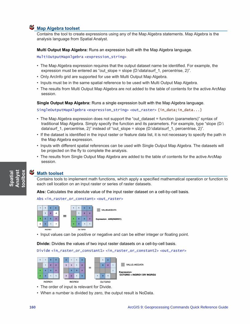
Spat
ial
Ana
lyst
to
olbo
x
160 ArcGIS 9: Geoprocessing Commands Quick Reference Guide
Map Algebra toolset Contains the tool to create expressions using any of the Map Algebra statements. Map Algebra is the analysis language from Spatial Analyst.
Multi Output Map Algebra: Runs an expression built with the Map Algebra language.MultiOutputMapAlgebra <expression_string>
• TheMapAlgebraexpressionrequiresthattheoutputdatasetnamebeidentified.Forexample,theexpressionmustbeenteredas“out_slope=slope(D:\data\surf_1,percentrise,2)”.
• OnlyArcInfogridaresupportedforusewithMultiOutputMapAlgebra.• InputsmustbeinthesamespatialreferencetobeusedwithMultiOutputMapAlgebra.• TheresultsfromMultiOutputMapAlgebraarenotaddedtothetableofcontentsfortheactiveArcMap
session.
Single Output Map Algebra: Runs a single expression built with the Map Algebra language.SingleOutputMapAlgebra <expression_string> <out_raster> {in_data;in_data...}
• TheMapAlgebraexpressiondoesnotsupportthe“out_dataset=function(parameters)”syntaxoftraditionalMapAlgebra.Simplyspecifythefunctionanditsparameters.Forexample,type“slope(D:\data\surf_1,percentrise,2)”insteadof“out_slope=slope(D:\data\surf_1,percentrise,2)”.
• Ifthedatasetisidentifiedintheinputrasterorfeaturedatalist,itisnotnecessarytospecifythepathinthe Map Algebra expression.
• InputswithdifferentspatialreferencescanbeusedwithSingleOutputMapAlgebra.Thedatasetswillbeprojectedontheflytocompletetheanalysis.
• TheresultsfromSingleOutputMapAlgebraareaddedtothetableofcontentsfortheactiveArcMapsession.
Math toolset Containstoolstoimplementmathfunctions,whichapplyaspecifiedmathematicaloperationorfunctiontoeach cell location on an input raster or series of raster datasets.
Abs: Calculates the absolute value of the input raster dataset on a cell-by-cell basis.Abs <in_raster_or_constant> <out_raster>
• Inputvaluescanbepositiveornegativeandcanbeeitherintegerorfloatingpoint.
Divide: Divides the values of two input raster datasets on a cell-by-cell basis.Divide <in_raster_or_constant1> <in_raster_or_constant2> <out_raster>
• TheorderofinputisrelevantforDivide.• Whenanumberisdividedbyzero,theoutputresultisNoData.
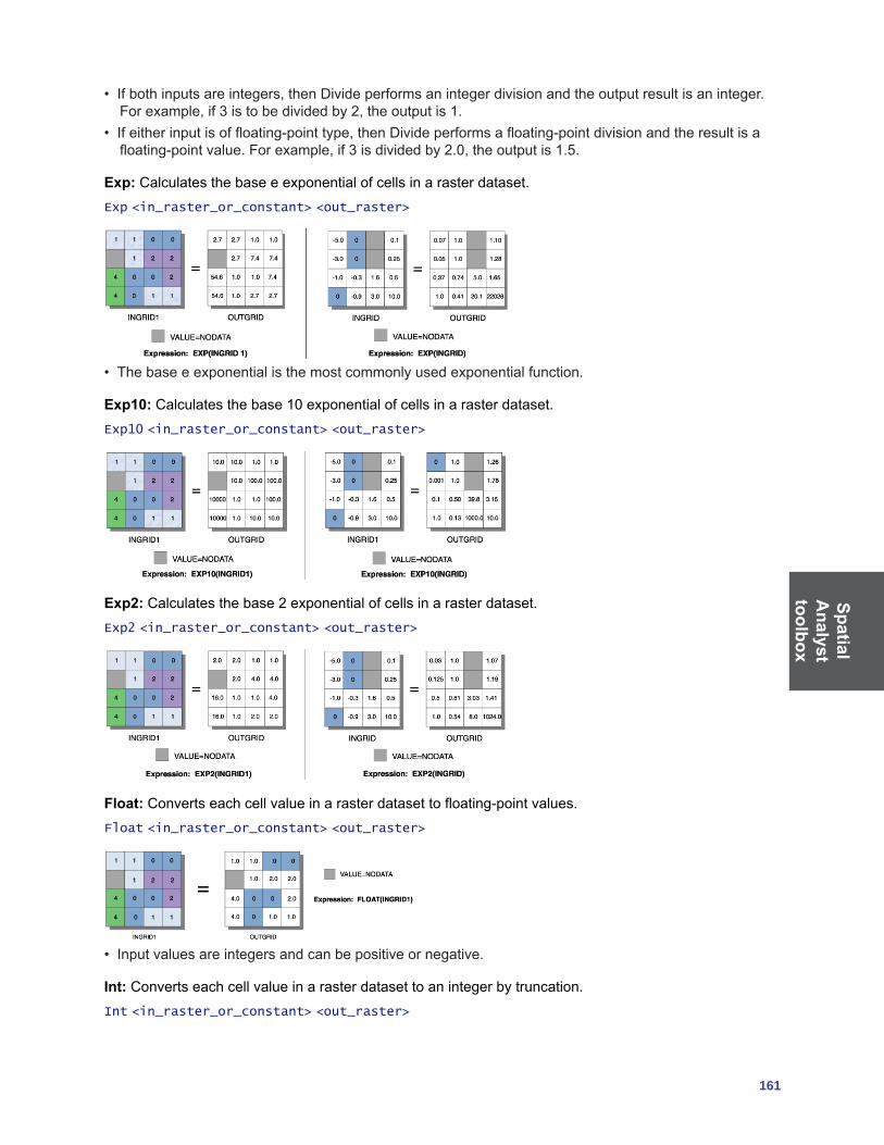
SpatialA
nalysttoolbox
161
• Ifbothinputsareintegers,thenDivideperformsanintegerdivisionandtheoutputresultisaninteger.Forexample,if3istobedividedby2,theoutputis1.
• Ifeitherinputisoffloating-pointtype,thenDivideperformsafloating-pointdivisionandtheresultisafloating-pointvalue.Forexample,if3isdividedby2.0,theoutputis1.5.
Exp: Calculates the base e exponential of cells in a raster dataset.Exp <in_raster_or_constant> <out_raster>
• Thebaseeexponentialisthemostcommonlyusedexponentialfunction.
Exp10: Calculates the base 10 exponential of cells in a raster dataset.Exp10 <in_raster_or_constant> <out_raster>
Exp2: Calculates the base 2 exponential of cells in a raster dataset.Exp2 <in_raster_or_constant> <out_raster>
Float: Convertseachcellvalueinarasterdatasettofloating-pointvalues.Float <in_raster_or_constant> <out_raster>
• Inputvaluesareintegersandcanbepositiveornegative.
Int: Converts each cell value in a raster dataset to an integer by truncation.Int <in_raster_or_constant> <out_raster>
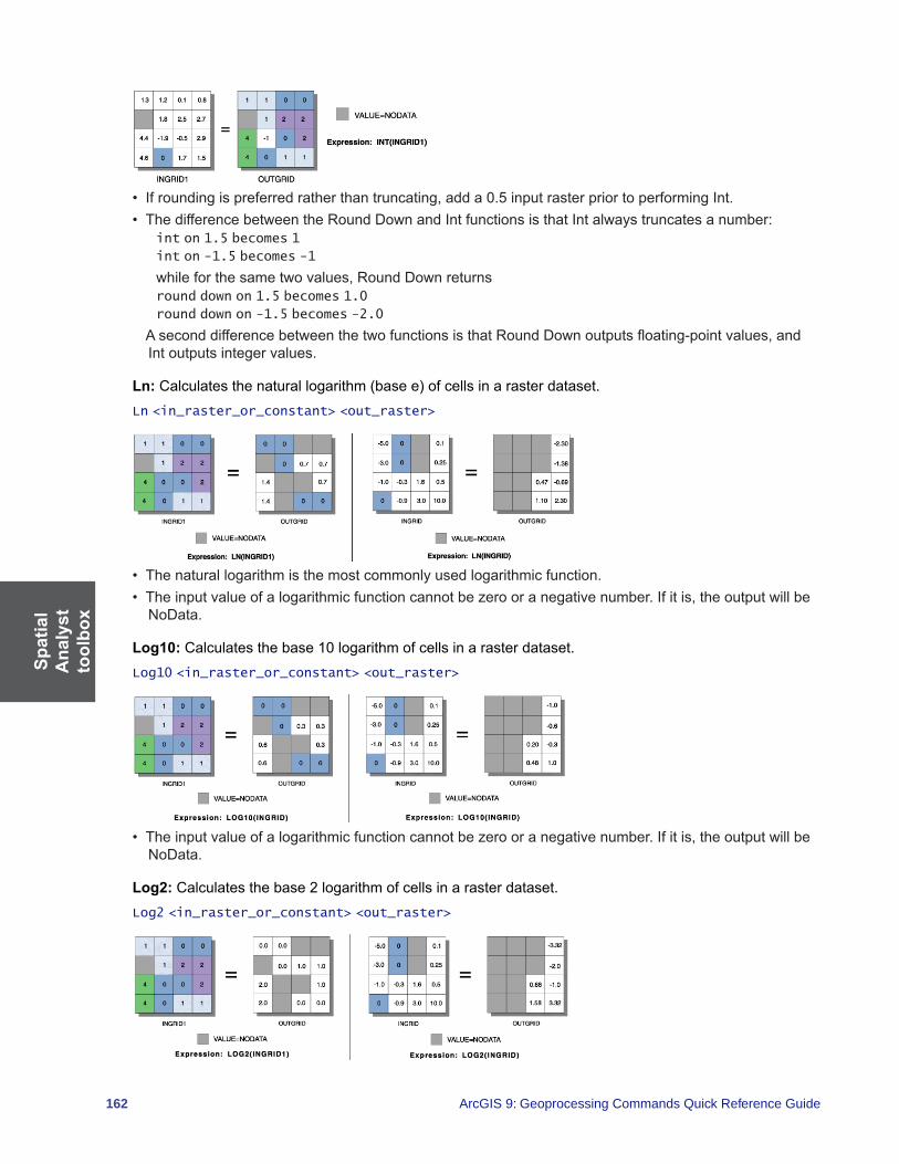
Spat
ial
Ana
lyst
to
olbo
x
162 ArcGIS 9: Geoprocessing Commands Quick Reference Guide
• Ifroundingispreferredratherthantruncating,adda0.5inputrasterpriortoperformingInt.• ThedifferencebetweentheRoundDownandIntfunctionsisthatIntalwaystruncatesanumber:
int on 1.5 becomes 1
int on -1.5 becomes -1
whileforthesametwovalues,RoundDownreturnsround down on 1.5 becomes 1.0
round down on -1.5 becomes -2.0
AseconddifferencebetweenthetwofunctionsisthatRoundDownoutputsfloating-pointvalues,andInt outputs integer values.
Ln:Calculatesthenaturallogarithm(basee)ofcellsinarasterdataset.Ln <in_raster_or_constant> <out_raster>
• Thenaturallogarithmisthemostcommonlyusedlogarithmicfunction.• Theinputvalueofalogarithmicfunctioncannotbezerooranegativenumber.Ifitis,theoutputwillbe
NoData.
Log10: Calculates the base 10 logarithm of cells in a raster dataset.Log10 <in_raster_or_constant> <out_raster>
• Theinputvalueofalogarithmicfunctioncannotbezerooranegativenumber.Ifitis,theoutputwillbeNoData.
Log2: Calculates the base 2 logarithm of cells in a raster dataset.Log2 <in_raster_or_constant> <out_raster>
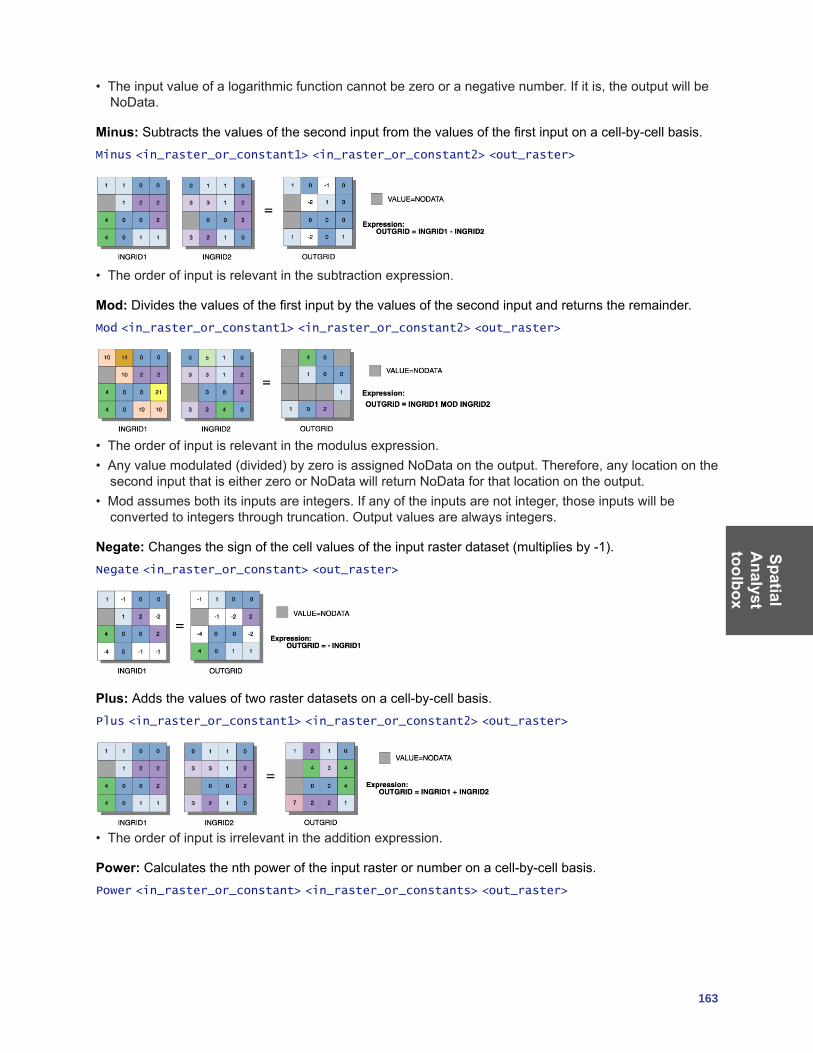
SpatialA
nalysttoolbox
163
• Theinputvalueofalogarithmicfunctioncannotbezerooranegativenumber.Ifitis,theoutputwillbeNoData.
Minus:Subtractsthevaluesofthesecondinputfromthevaluesofthefirstinputonacell-by-cellbasis.Minus <in_raster_or_constant1> <in_raster_or_constant2> <out_raster>
• Theorderofinputisrelevantinthesubtractionexpression.
Mod: Dividesthevaluesofthefirstinputbythevaluesofthesecondinputandreturnstheremainder.Mod <in_raster_or_constant1> <in_raster_or_constant2> <out_raster>
• Theorderofinputisrelevantinthemodulusexpression.• Anyvaluemodulated(divided)byzeroisassignedNoDataontheoutput.Therefore,anylocationonthesecondinputthatiseitherzeroorNoDatawillreturnNoDataforthatlocationontheoutput.
• Modassumesbothitsinputsareintegers.Ifanyoftheinputsarenotinteger,thoseinputswillbeconvertedtointegersthroughtruncation.Outputvaluesarealwaysintegers.
Negate:Changesthesignofthecellvaluesoftheinputrasterdataset(multipliesby-1).Negate <in_raster_or_constant> <out_raster>
Plus: Adds the values of two raster datasets on a cell-by-cell basis.Plus <in_raster_or_constant1> <in_raster_or_constant2> <out_raster>
• Theorderofinputisirrelevantintheadditionexpression.
Power: Calculates the nth power of the input raster or number on a cell-by-cell basis.Power <in_raster_or_constant> <in_raster_or_constants> <out_raster>

Spat
ial
Ana
lyst
to
olbo
x
164 ArcGIS 9: Geoprocessing Commands Quick Reference Guide
Round Down: Returns the next lower whole number value for each cell in a raster dataset.RoundDown <in_raster_or_constant> <out_raster>
• Ifanumberhasanyvaluestotherightofthedecimalpoint,theoutputwillbeassignedthenextlowestwhole value:Input Output 5.3 5.0 4.9 4.0 3.0 3.06.5 6.0 -0.2 -1.0 -2.8 -3.0
• ThedifferencebetweenRoundDownandIntisthatIntalwaystruncatesanumber:int on 1.5 becomes 1
int on -1.5 becomes -1
while Round Down returns the next lower whole number:Round Down on 1.5 becomes 1.0
Round Down on -1.5 becomes -2.0
AseconddifferenceisthatRoundDownoutputsfloating-pointvalueswhileIntoutputsintegervalues.
Round Up: Returnsthenexthighestwholenumbervaluethatisgreaterthanorequaltotheinputvaluefor each cell in a raster dataset.
RoundUp <in_raster_or_constant> <out_raster>
• Ifanumberhasanyvaluestotherightofthedecimalpoint,theoutputwillbeassignedthenexthighestwhole value:Input Output5.3 6.0 4.9 5.0 3.0 3.06.5 7.0 -0.2 0.0 -2.8 -2.0
Square:Calculatesthesquareofcellvaluesinarasterdataset.Square <in_raster_or_constant> <out_raster>

SpatialA
nalysttoolbox
165
Square Root:Calculatesthesquarerootoftheinputgridornumberforeachcell.SquareRoot <in_raster_or_constant> <out_raster>
• Inputvaluesmustbegreaterthanorequaltozero.Iftheyarenot,theoutputwillbeNoData.
Times: Multiplies the values of two raster datasets on a cell-by-cell basis.Times <in_raster_or_constant1> <in_raster_or_constant2> <out_raster>
• Theorderofinputisirrelevantinthemultiplicationexpression.
Bitwise (Math) toolset Containstoolstoimplementbitwiseoperators,whichtreattheoperandsasbits(binaryrepresentations)and calculate the output by applying the logical operation (e.g.,3BITWISEAND5=0011&&0101=0001=1).
Bitwise And:PerformsthebitwiseANDoperationonthebinaryvaluesoftwoinputsonacell-by-cellbasis(e.g.,0011&&0101=0001).
BitwiseAnd <in_raster_or_constant1> <in_raster_or_constant2> <out_raster>
• Thebitwisemethodsworkon32-bitintegers.• Iffloating-pointvaluesareinput,theyareconvertedtointegervaluesthroughtruncationbeforethe
bitwise method is performed. The output values are always integers.• Binaryvaluesarestoredintwo’scomplement.• Theleftmostbitpositionisreservedforthesignofthevalue(positiveornegative).Iftheintegerispositive,thebitiszero;ifnegative,thebitis1.
• BitwiseAndtreatsthesignbitasitwouldanyotherbit.Ifoneorbothinputsforacelllocationarepositive,theoutputispositive;ifbothinputsarenegative,theoutputisnegative.
Bitwise Left Shift:Shiftsthebitstotheleftusingthenumberspecified (e.g.,1<<2=0001<<2=0100=4).
BitwiseLeftShift <in_raster_or_constant1> <in_raster_or_constant2> <out_raster>
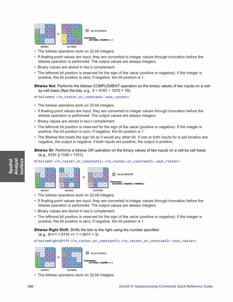
Spat
ial
Ana
lyst
to
olbo
x
166 ArcGIS 9: Geoprocessing Commands Quick Reference Guide
• Thebitwiseoperatorsworkon32-bitintegers.• Iffloating-pointvaluesareinput,theyareconvertedtointegervaluesthroughtruncationbeforethe
bitwise operation is performed. The output values are always integers.• Binaryvaluesarestoredintwo’scomplement.• Theleftmostbitpositionisreservedforthesignofthevalue(positiveornegative).Iftheintegerispositive,thebitpositioniszero;ifnegative,thebitpositionis1.
Bitwise Not:PerformsthebitwiseCOMPLEMENToperationonthebinaryvaluesoftwoinputsonacell-by-cellbasis(flipsthebits;e.g.,5=0101~1010=10).
BitwiseNot <in_raster_or_constant> <out_raster>
• Thebitwiseoperatorsworkon32-bitintegers.• Iffloating-pointvaluesareinput,theyareconvertedtointegervaluesthroughtruncationbeforethe
bitwise operation is performed. The output values are always integers.• Binaryvaluesarestoredintwo’scomplement.• Theleftmostbitpositionisreservedforthesignofthevalue(positiveornegative).Iftheintegerispositive,thebitpositioniszero;ifnegative,thebitpositionis1.
• TheBitwiseNottreatsthesignbitasitwouldanyotherbit.Ifoneorbothinputsforacelllocationarenegative,theoutputisnegative;ifbothinputsarepositive,theoutputispositive.
Bitwise Or:PerformsabitwiseORoperationonthebinaryvaluesoftwoinputsonacell-by-cellbasis(e.g.,0101||1100=1101).
BitwiseOr <in_raster_or_constant1> <in_raster_or_constant2> <out_raster>
• Thebitwiseoperatorsworkon32-bitintegers.• Iffloating-pointvaluesareinput,theyareconvertedtointegervaluesthroughtruncationbeforethe
bitwise operation is performed. The output values are always integers.• Binaryvaluesarestoredintwo’scomplement.• Theleftmostbitpositionisreservedforthesignofthevalue(positiveornegative).Iftheintegerispositive,thebitpositioniszero;ifnegative,thebitpositionis1.
Bitwise Right Shift:Shiftsthebitstotherightusingthenumberspecified (e.g.,6>>1=0110>>1=0011=3).
BitwiseRightShift <in_raster_or_constant1> <in_raster_or_constant2> <out_raster>
• Thebitwiseoperatorsworkon32-bitintegers.
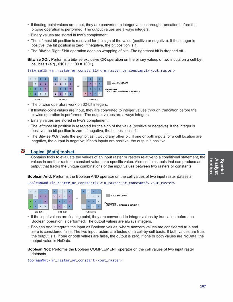
SpatialA
nalysttoolbox
167
• Iffloating-pointvaluesareinput,theyareconvertedtointegervaluesthroughtruncationbeforethebitwise operation is performed. The output values are always integers.
• Binaryvaluesarestoredintwo’scomplement.• Theleftmostbitpositionisreservedforthesignofthevalue(positiveornegative).Iftheintegerispositive,thebitpositioniszero;ifnegative,thebitpositionis1.
• TheBitwiseRightShiftoperationdoesnowrappingofbits.Therightmostbitisdroppedoff.
Bitwise XOr:PerformsabitwiseexclusiveORoperationonthebinaryvaluesoftwoinputsonacell-by-cellbasis(e.g.,0101!!1100=1001).
BitwiseXOr <in_raster_or_constant1> <in_raster_or_constant2> <out_raster>
• Thebitwiseoperatorsworkon32-bitintegers.• Iffloating-pointvaluesareinput,theyareconvertedtointegervaluesthroughtruncationbeforethe
bitwise operation is performed. The output values are always integers.• Binaryvaluesarestoredintwo’scomplement.• Theleftmostbitpositionisreservedforthesignofthevalue(positiveornegative).Iftheintegerispositive,thebitpositioniszero;ifnegative,thebitpositionis1.
• TheBitwiseXOrtreatsthesignbitasitwouldanyotherbit.Ifoneorbothinputsforacelllocationarenegative,theoutputisnegative;ifbothinputsarepositive,theoutputispositive.
Logical (Math) toolset Containstoolstoevaluatethevaluesofaninputrasterorrastersrelativetoaconditionalstatement,thevaluesinanotherraster,aconstantvalue,oraspecificvalue.Alsocontainstoolsthatcanproduceanoutputthattrackstheuniquecombinationsoftheinputvaluesbetweentworastersorconstants.
Boolean And: PerformstheBooleanANDoperatoronthecellvaluesoftwoinputrasterdatasets.BooleanAnd <in_raster_or_constant1> <in_raster_or_constant2> <out_raster>
• Iftheinputvaluesarefloatingpoint,theyareconvertedtointegervaluesbytruncationbeforetheBooleanoperationisperformed.Theoutputvaluesarealwaysintegers.
• BooleanAndinterpretstheinputasBooleanvalues,wherenonzerovaluesareconsideredtrueandzeroisconsideredfalse.Thetwoinputrastersaretestedonacell-by-cellbasis.Ifbothvaluesaretrue,theoutputis1.Ifoneorbothvaluesarefalse,theoutputiszero.IfoneorbothvaluesareNoData,theoutput value is NoData.
Boolean Not:PerformstheBooleanCOMPLEMENToperatoronthecellvaluesoftwoinputrasterdatasets.
BooleanNot <in_raster_or_constant> <out_raster>

Spat
ial
Ana
lyst
to
olbo
x
168 ArcGIS 9: Geoprocessing Commands Quick Reference Guide
• Iftheinputvaluesarefloatingpoint,theyareconvertedtointegersbytruncationbeforetheBooleanNotis performed. The output values are always integers.
• BooleanNotinterpretstheinputasBooleanvalues,wherenonzerovaluesareconsideredtrueandzeroisconsideredfalse.Theinputrasteristestedonacell-by-cellbasis.Ifthevalueistrue,theoutputiszero(thecomplementoftrue).Ifthevalueisfalse,theoutputis1.IfthevalueisNoData,theoutputvalue is NoData.
Boolean Or: PerformstheBooleanORoperatoronthecellvaluesoftwoinputrasterdatasets.BooleanOr <in_raster_or_constant1> <in_raster_or_constant2> <out_raster>
• Iftheinputvaluesarefloatingpoint,theyareconvertedtointegervaluesbytruncationbeforetheBooleanmethodisperformed.Outputvaluesarealwaysintegers.
• BooleanOrinterpretstheinputasBooleanvalues,wherenonzerovaluesareconsideredtrueandzerois considered false. The two input rasters are tested on a cell-by-cell basis. If one or both values are true,theoutputis1.Ifbothvaluesarefalse,theoutputiszero.IfoneorbothvaluesareNoData,theoutput value is NoData.
Boolean XOr:PerformstheBooleanexclusiveORoperatoronthecellvaluesoftwoinputrasterdatasets.
BooleanXOr <in_raster_or_constant1> <in_raster_or_constant2> <out_raster>
• Iftheinputvaluesarefloatingpoint,theyareconvertedtointegervaluesbytruncationbeforetheBooleanmethodisperformed.Theoutputvaluesarealwaysintegers.
• BooleanXOrinterpretstheinputasBooleanvalues,wherenonzerovaluesareconsideredtrueandzeroisconsideredfalse.Thetwoinputrastersaretestedonacell-by-cellbasis.IfonevalueisTrueandonevalueisfalse,theoutputis1.Ifbothvaluesaretrueorbotharefalse,theoutputiszero.IfoneorbothvaluesareNoData,theoutputvalueisNoData.
Combinatorial And: PerformsacombinatorialANDoperationontwoinputrasterdatasets.CombinatorialAnd <in_raster_or_constant1> <in_raster_or_constant2> <out_raster>

SpatialA
nalysttoolbox
169
• Bothinputsmustcontainpositiveintegervalues.
Combinatorial Or:PerformsacombinatorialORoperationonthecellvaluesoftwoinputrasterdatasets.CombinatorialOr <in_raster_or_constant1> <in_raster_or_constant2> <out_raster>
• Bothinputsmustcontainpositiveintegervalues.
Combinatorial XOr:PerformsacombinatorialexclusiveORoperationonthecellvaluesoftwoinputraster datasets.
CombinatorialXOr <in_raster_or_constant1> <in_raster_or_constant2> <out_raster>
• Bothinputsmustcontainpositiveintegervalues.
Diff: Determineswhichvaluesfromthefirstinputarelogicallydifferentfromthevaluesofthesecondinput on a cell-by-cell basis.
Diff <in_raster_or_constant1> <in_raster_or_constant2> <out_raster>
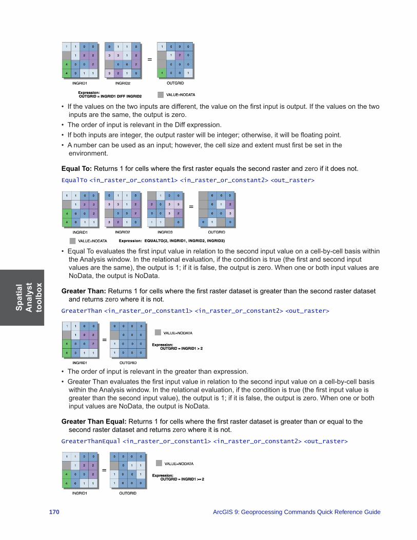
Spat
ial
Ana
lyst
to
olbo
x
170 ArcGIS 9: Geoprocessing Commands Quick Reference Guide
• Ifthevaluesonthetwoinputsaredifferent,thevalueonthefirstinputisoutput.Ifthevaluesonthetwoinputsarethesame,theoutputiszero.
• TheorderofinputisrelevantintheDiffexpression.• Ifbothinputsareinteger,theoutputrasterwillbeinteger;otherwise,itwillbefloatingpoint.• Anumbercanbeusedasaninput;however,thecellsizeandextentmustfirstbesetinthe
environment.
Equal To: Returns1forcellswherethefirstrasterequalsthesecondrasterandzero if it does not.EqualTo <in_raster_or_constant1> <in_raster_or_constant2> <out_raster>
• EqualToevaluatesthefirstinputvalueinrelationtothesecondinputvalueonacell-by-cellbasiswithintheAnalysiswindow.Intherelationalevaluation,iftheconditionistrue(thefirstandsecondinputvaluesarethesame),theoutputis1;ifitisfalse,theoutputiszero.WhenoneorbothinputvaluesareNoData,theoutputisNoData.
Greater Than:Returns1forcellswherethefirstrasterdatasetisgreaterthanthesecondrasterdatasetand returns zero where it is not.
GreaterThan <in_raster_or_constant1> <in_raster_or_constant2> <out_raster>
• Theorderofinputisrelevantinthegreaterthanexpression.• GreaterThanevaluatesthefirstinputvalueinrelationtothesecondinputvalueonacell-by-cellbasiswithintheAnalysiswindow.Intherelationalevaluation,iftheconditionistrue(thefirstinputvalueisgreaterthanthesecondinputvalue),theoutputis1;ifitisfalse,theoutputiszero.WhenoneorbothinputvaluesareNoData,theoutputisNoData.
Greater Than Equal:Returns1forcellswherethefirstrasterdatasetisgreaterthanorequaltothesecond raster dataset and returns zero where it is not.
GreaterThanEqual <in_raster_or_constant1> <in_raster_or_constant2> <out_raster>

SpatialA
nalysttoolbox
171
• Theorderofinputisrelevantinthegreaterthanequalexpression.• GreaterThanEqualevaluatesthefirstinputvalueinrelationtothesecondinputvalueonacell-by-cellbasiswithintheAnalysiswindow.Intherelationalevaluation,iftheconditionistrue(thefirstinputvalueisgreaterthanorequaltothesecondinputvalue),theoutputis1;ifitisfalse,theoutputiszero.WhenoneorbothinputvaluesareNoData,theoutputisNoData.
InList: Determineswhichvaluesfromthefirstinputarecontainedintheotherinputs,onacell-by-cellbasis.
InList <in_raster_or_constant1> <in_raster_or_constant2;in_raster_or_constant2...> <out_raster>
• Ifthefirstinputisarasterandthevalueofacelllocationisnotcontainedinthesetspecifiedbythesecondinput,thelocationwillreceiveNoDataontheoutputraster.
• Ifalltheinputsareintegers,theoutputrasterwillbeinteger;otherwise,itwillbefloatingpoint.• Anumbercanbeusedasaninput;however,thecellsizeandextentmustfirstbesetinthe
environment.
Is Null: Returns 1 for cells in the input raster dataset that have a value of NoData and returns zero where they do not.
IsNull <in_raster> <out_raster>
• Theoutputvaluetypeisalwaysinteger.Thevaluesareeither1orzero.Cellsintheinputthathaveavaluearegivenzeroontheoutput.CellsthatareNoDataintheinputaregivenavalueof1ontheoutput.
Less Than:Returns1forcellswherethefirstrasterdatasetislessthanthesecondrasterdatasetandreturns zero where it is not.
LessThan <in_raster_or_constant1> <in_raster_or_constant2> <out_raster>
• Theorderofinputisrelevantinthelessthanexpression.• LessThanevaluatesthefirstinputvalueinrelationtothesecondinputvalueonacell-by-cellbasiswithintheAnalysiswindow.Intherelationalevaluation,iftheconditionistrue(thefirstinputvalueislessthanthesecondinputvalue),theoutputis1;ifitisfalse,theoutputiszero.WhenoneorbothinputvaluesareNoData,theoutputisNoData.
Less Than Equal:Returns1forcellswherethefirstrasterdatasetislessthanorequaltothesecondraster dataset and returns zero where it is not.
LessThanEqual <in_raster_or_constant1> <in_raster_or_constant2> <out_raster>
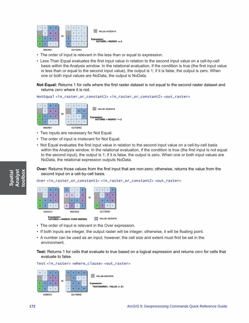
Spat
ial
Ana
lyst
to
olbo
x
172 ArcGIS 9: Geoprocessing Commands Quick Reference Guide
• Theorderofinputisrelevantinthelessthanorequaltoexpression.• LessThanEqualevaluatesthefirstinputvalueinrelationtothesecondinputvalueonacell-by-cellbasiswithintheAnalysiswindow.Intherelationalevaluation,iftheconditionistrue(thefirstinputvalueislessthanorequaltothesecondinputvalue),theoutputis1;ifitisfalse,theoutputiszero.WhenoneorbothinputvaluesareNoData,theoutputisNoData.
Not Equal:Returns1forcellswherethefirstrasterdatasetisnotequaltothesecondrasterdatasetandreturns zero where it is not.
NotEqual <in_raster_or_constant1> <in_raster_or_constant2> <out_raster>
• TwoinputsarenecessaryforNotEqual.• TheorderofinputisirrelevantforNotEqual.• NotEqualevaluatesthefirstinputvalueinrelationtothesecondinputvalueonacell-by-cellbasiswithintheAnalysiswindow.Intherelationalevaluation,iftheconditionistrue(thefirstinputisnotequaltothesecondinput),theoutputis1;ifitisfalse,theoutputiszero.WhenoneorbothinputvaluesareNoData,therelationalexpressionoutputsNoData.
Over: Returnsthosevaluesfromthefirstinputthatarenon-zero;otherwise,returnsthevaluefromthesecond input on a cell-by-cell basis.
Over <in_raster_or_constant1> <in_raster_or_constant2> <out_raster>
• TheorderofinputisrelevantintheOverexpression.• Ifbothinputsareinteger,theoutputrasterwillbeinteger;otherwise,itwillbefloatingpoint.• Anumbercanbeusedasaninput;however,thecellsizeandextentmustfirstbesetinthe
environment.
Test: Returns 1 for cells that evaluate to true based on a logical expression and returns zero for cells that evaluate to false.
Test <in_raster> <where_clause> <out_raster>

SpatialA
nalysttoolbox
173
• Theoutputiseither1(ifthetestevaluatestotrue)orzero(ifthetestevaluatestofalse).• ThetestisspecifiedbyaSQLexpression.
Trigonometric (Math) toolset Contains tools for the trigonometric functions that are applied on a per-cell basis to an input raster dataset.
ACos: Calculates the inverse cosine of the input raster dataset or number on a cell-by-cell basis.ACos <in_raster_or_constant> <out_raster>
• TheinputvaluestotheACosfunctionmustbeequaltoorbetween-1and1.Anyvalueoutsidethisrange will receive NoData on the output raster.
• TheinputvaluestotheACosfunctionareinterpretedasunitless.• TheoutputvaluesfromACosareinradians.Ifdegreesaredesired,theresultingrastermustbemultipliedbytheradians-to-degreesconversionfactorof180/π,orapproximately57.296.
ACosH: Calculates the inverse hyperbolic cosine of cells in an input raster dataset.ACosH <in_raster_or_constant> <out_raster>
• TheinputvaluestotheACosHfunctionmustbegreaterthanorequalto1.Anyvaluebelow1willreceive NoData on the output.
• TheinputandoutputvaluesinACosHareinterpretedasunitless.
ASin: Calculates the inverse sine of cells in an input raster dataset.ASin <in_raster_or_constant> <out_raster>
• TheinputvaluestoASinmustbebetween-1and1.AnyvalueoutsidethisrangewillreceiveNoDataon the output.
• TheinputvaluestoASinareinterpretedasunitless.• TheoutputvaluesfromASinareinradians.Ifdegreesaredesired,theresultingrastermustbemultipliedbytheradians-to-degreesconversionfactorof180/π,orapproximately57.296.

Spat
ial
Ana
lyst
to
olbo
x
174 ArcGIS 9: Geoprocessing Commands Quick Reference Guide
ASinH: Calculates the inverse hyperbolic sine of cells in an input raster dataset.ASinH <in_raster_or_constant> <out_raster>
• Outputvaluesarealwaysfloatingpoint,nomatterwhattheinputvaluesare.• ThereisnolimitontheinputvaluestoASinH.• TheinputandoutputvaluesinASinHareinterpretedasunitless.
ATan: Calculates the inverse tangent of cells in an input raster dataset.ATan <in_raster_or_constant> <out_raster>
• TheinputvaluestotheATanfunctionareinterpretedasunitless.• TheoutputvaluesfromATanareinradians.Ifdegreesaredesired,theresultingrastermustbemultipliedbytheradians-to-degreesconversionfactorof180/π,orapproximately57.296.
ATan2: Calculatestheinversetangent(basedony/x)ofcellsinaninputrasterdataset.ATan2 <in_raster_or_constant1> <in_raster_or_constant2> <out_raster>
• Thevaluesofthefirstspecifiedinputareusedasthenumeratorinthecalculationofthetangentangle(tan@=y/x).Thevaluesofthesecondspecifiedinputareusedasthedenominatorinthecalculationofthe angle.
• TheoutputvaluesfromtheATan2functionarebetween-piandpi.ThearctangenttwooperationrepresentsallquadrantsinaCartesianmatrix(basedonsign).
• ATan2convertsrectangularcoordinates(x,y)topolar(r,th),whereristhedistancefromtheoriginandth is the angle from the x-axis.
• TheinputvaluestoATan2areinterpretedasunitless.• TheoutputvaluesfromATan2areinradians.Ifdegreesaredesired,theresultingrastermustbemultipliedbytheradians-to-degreesconversionfactorof180/π,orapproximately57.296.

SpatialA
nalysttoolbox
175
ATanH: Calculates the inverse hyperbolic tangent of cells in an input raster dataset.ATanH <in_raster_or_constant> <out_raster>
• TheinputandoutputvaluesinATanHareinterpretedasunitless.• TheinputvaluestoATanHmustbebetween-1and1.Anyinputvalueoutsidethisrangewillresultin
NoData on the output raster.
Cos: Calculates the cosine of cells in an input raster dataset.Cos <in_raster_or_constant> <out_raster>
• Thecosineofavalueisbetween-1and1.• TheinputvaluestoCosareinterpretedasradians.Ifthedesiredinputisindegrees,thevaluesmustbedividedbytheradians-to-degreesconversionfactorof180/π,orapproximately57.296.
CosH: Calculates the hyperbolic cosine of cells in an input raster dataset.CosH <in_raster_or_constant> <out_raster>
• TheinputandoutputvaluesinCosHareinterpretedasunitless.
Sin: Calculates the sine of cells in an input raster dataset.Sin <in_raster_or_constant> <out_raster>
• Thesineofavalueisbetween-1and1.• TheinputvaluestoSinareinterpretedasradians.Ifthedesiredinputisindegrees,thevaluesmustbedividedbytheradians-to-degreesconversionfactorof180/π,orapproximately57.296.
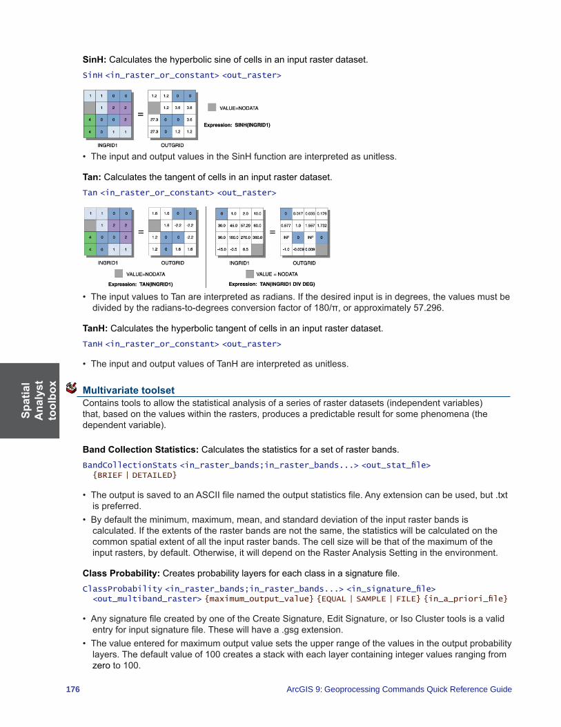
Spat
ial
Ana
lyst
to
olbo
x
176 ArcGIS 9: Geoprocessing Commands Quick Reference Guide
SinH: Calculates the hyperbolic sine of cells in an input raster dataset.SinH <in_raster_or_constant> <out_raster>
• TheinputandoutputvaluesintheSinHfunctionareinterpretedasunitless.
Tan: Calculates the tangent of cells in an input raster dataset.Tan <in_raster_or_constant> <out_raster>
• TheinputvaluestoTanareinterpretedasradians.Ifthedesiredinputisindegrees,thevaluesmustbedividedbytheradians-to-degreesconversionfactorof180/π,orapproximately57.296.
TanH: Calculates the hyperbolic tangent of cells in an input raster dataset.TanH <in_raster_or_constant> <out_raster>
• TheinputandoutputvaluesofTanHareinterpretedasunitless.
Multivariate toolset Containstoolstoallowthestatisticalanalysisofaseriesofrasterdatasets(independentvariables)that,basedonthevalueswithintherasters,producesapredictableresultforsomephenomena(thedependentvariable).
Band Collection Statistics: Calculates the statistics for a set of raster bands.BandCollectionStats <in_raster_bands;in_raster_bands...> <out_stat_file> {BRIEF | DETAILED}
• TheoutputissavedtoanASCIIfilenamedtheoutputstatisticsfile.Anyextensioncanbeused,but.txtis preferred.
• Bydefaulttheminimum,maximum,mean,andstandarddeviationoftheinputrasterbandsiscalculated.Iftheextentsoftherasterbandsarenotthesame,thestatisticswillbecalculatedonthecommonspatialextentofalltheinputrasterbands.Thecellsizewillbethatofthemaximumoftheinputrasters,bydefault.Otherwise,itwilldependontheRasterAnalysisSettingintheenvironment.
Class Probability: Createsprobabilitylayersforeachclassinasignaturefile.ClassProbability <in_raster_bands;in_raster_bands...> <in_signature_file> <out_multiband_raster> {maximum_output_value} {EQUAL | SAMPLE | FILE} {in_a_priori_file}
• AnysignaturefilecreatedbyoneoftheCreateSignature,EditSignature,orIsoClustertoolsisavalidentryforinputsignaturefile.Thesewillhavea.gsgextension.
• Thevalueenteredformaximumoutputvaluesetstheupperrangeofthevaluesintheoutputprobabilitylayers. The default value of 100 creates a stack with each layer containing integer values ranging from zero to 100.

SpatialA
nalysttoolbox
177
• TheinputaprioriprobabilityfilemustbeanASCIIfileconsistingoftwocolumns.Thevaluesintheleftcolumn represent class IDs. The values in the right column represent the a priori probabilities for the respectiveclasses.Validvaluesforclassaprioriprobabilitiesmustbegreaterthanorequaltozero. If zeroisspecifiedasaprobability,theclasswillnotappearontheoutputraster.Thesumofthespecifiedaprioriprobabilitiesmustbesmallerthanorequalto1.Theformatofthefileisasfollows:
1 .32 .14 .05 .157 .058 .2
Theclassesomittedinthefilewillreceivetheaverageaprioriprobabilityoftheremainingportionofthevalue of 1.
Create Signatures:CreatesanASCIIsignaturefileofclassesdefinedbyinputsampledataandasetofraster bands.
CreateSignatures <in_raster_bands;in_raster_bands...> <in_sample_data> <out_signature_file> {COVARIANCE | MEAN_ONLY} {sample_field}
• Theminimumvalidnumberofclasssamplesinthesampledatais2.Thereisnomaximumnumberofclasses.
• TheCOVARIANCEoptionmustbeusedifthesignaturefileistobeusedinfurthermultivariateanalysisfunctionsthatusecovariancematrices,suchasMaximumLikelihoodClassificationandClassProbability.Thisisthedefault.
Dendrogram:Constructsatreediagramshowingattributedistancesbetweensequentiallymergedclassesinasignaturefile.
Dendrogram <in_signature_file> <out_dendrogram_file> {VARIANCE | MEAN_ONLY} {line_width}
• TheinputsignaturefilehastobeasignaturefileintheprescribedASCIIformat.AsignaturefilecanbecreatedwiththeIsoClusterorCreateSignaturestool.Thefilemusthaveaminimumoftwoclasses.
• TheoutputofDendrogram,theoutputdendrogramfile,isanASCIIfile.Thefilecontainsatableofdistancesbetweenpairsofsequentiallymergedclassesandagraphicalrepresentationshowingtherelationshipsamongclassesandthehierarchyofthemerging.Byanalyzingthegraphandtheassociatedtable,ausercandecidethepotentialmergingofclasses.
• Theproximityofapairofclasseswithinasignaturefileismeasuredbytheattributedistance.
Edit Signatures: Editsandupdatesasignaturefilebymerging,renumbering,anddeletingclasssignatures.
EditSignatures <in_raster_bands;in_raster_bands...> <in_signature_file> <in_signature_remap_file> <out_signature_file> {sample_interval}
• EditSignaturesallowsthemodificationofanexistingsignaturefilebyalloranyofthefollowingoperations:• Mergingsignaturesofasetofclasses• RenumberingasignatureclassID• Deletingunwantedsignatures
• TheinputsignaturefilehastobeanASCIIsignaturefile.ThefilecanbeoutputofanyMultivariatefunctionthatproducesthefilecontainingtherequiredstatisticalinformation—forexample,IsoClusterandCreateSignatures.Thefilemusthaveaminimumoftwoclasses.Suchafilecanberecognizedbyits .gsg extension.
Spat
ial
Ana
lyst
to
olbo
x
178 ArcGIS 9: Geoprocessing Commands Quick Reference Guide
• TheinputsignatureremapfileisanASCIIfileconsistingoftwocolumns.Inthefirstcolumn,theoriginalclass IDs are listed in ascending order. The second column has the new class IDs for updating in the signaturefile.Whenasetofclassesistobemerged,anewclassIDmustbeputinthesecondcolumnforeachclassIDoftheset.Onlyclassesthatneedtobeeditedhavetobeplacedinthesignatureremapfile.Anyclassnotpresentintheremapfilewillremainunchanged.Todeleteaclasssignature,thevalueof-9,999mustbeenteredinthesecondcolumnoftheremapfile.AclassIDcanalsoberenumberedtoavaluethatdoesnotexistintheinputsignaturefile.Thefollowingisanexampleoftheinputsignatureremapfile:
2 : 34 : 115 : -99999 : 3
Theexampleabovewillmergeclasses2and9withthree,class4with11,anddeleteclass5.
Iso Cluster: Uses an isodata clustering algorithm to determine the characteristics of the natural groupings ofcellsinmultidimensionalattributespaceandstorestheresultsinanoutputASCIIsignaturefile.
IsoCluster <in_raster_bands;in_raster_bands...> <out_signature_file> <number_classes> {number_iterations} {min_class_size} {sample_interval}
• IsoClusterperformsclusteringofthemultivariatedatacombinedinalistofinputrasters.Theresultingsignaturefilemaybeusedastheinputforaclassificationfunction,suchasMaximumLikelihoodClassification,producinganunsupervisedclassificationraster.
• Toprovidethesufficientstatisticsnecessarytogenerateasignaturefileforafutureclassification,each cluster should contain enough cells to accurately represent the cluster. The value entered for theminimumclasssizeshouldbeabout10timeslargerthanthenumberoflayersintheinputrasterbands.
• Generally,formorecellscontainedintheinputrastersextent,largervaluesforminimumclasssizeandsampleintervalshouldbespecified.Valuesenteredforthesampleintervalshouldbesmallenoughthatthe smallest desirable categories existing in the input data will be appropriately sampled.
• TheclassIDvaluesontheoutputsignaturefilestartfromoneandsequentiallyincreasetothenumberof input classes. The assignment of the class numbers is arbitrary.
• Betterresultswillbeobtainedifallinputrastershavethesamedataranges.
Maximum Likelihood Classification: Performsamaximumlikelihoodclassificationonasetofrasterdataset bands.
MLClassify <in_raster_bands;in_raster_bands...> <in_signature_file> <out_classified_raster> {0.0 | 0.005 | 0.01 | 0.025 | 0.05 | 0.1 | 0.25 | 0.5 | 0.75 | 0.9 | 0.95 | 0.975 | 0.99 | 0.995} {EQUAL | SAMPLE | FILE} {in_a_priori_file} {out_confidence_raster}
• AnysignaturefilecreatedbytheCreateSignature,EditSignature,orIsoClustertoolsisavalidentryfortheinputsignaturefile.Thesewillhavea.gsgextension.
• Bydefault,allcellsintheoutputrasterwillbeclassified,witheachclasshavingequalprobabilityweights attached to their signatures.
• TheinputaprioriprobabilityfilemustbeanASCIIfileconsistingoftwocolumns.Thevaluesintheleftcolumn represent class IDs. The values in the right column represent the a priori probabilities for the respectiveclasses.Validvaluesforclassaprioriprobabilitiesmustbegreaterthanorequaltozero. If zeroisspecifiedasaprobability,theclasswillnotappearontheoutputraster.Thesumofthespecifiedaprioriprobabilitiesmustbelessthanorequalto1.Theformatofthefileisasfollows:
1 .32 .14 .05 .157 .058 .2

SpatialA
nalysttoolbox
179
Theclassesomittedinthefilewillreceivetheaverageaprioriprobabilityoftheremainingportionofthevalue of 1.
• Aspecifiedrejectfraction,whichliesbetweenanytwovalidvalues,willbeassignedtothenextuppervalidvalue.Forexample,0.02willbecome0.025.
Principal Components:Performsprincipalcomponentsanalysisonasetofrasterbands.PrincipalComponents <in_raster_bands;in_raster_bands...> <out_multiband_raster> {number_components} {out_data_file}
• Thevaluespecifiedforthenumberofprincipalcomponentsdeterminesthenumberofprincipalcomponent layers in the output multiband raster. The number must not be larger than the total number of raster bands in the input.
• Withtheoutputdatafilenamespecified,thecorrelationandcovariancematrices,aswellastheeigenvaluesandeigenvectors,willbestoredinanASCIIfile.
Neighborhood toolset Contains tools to calculate a statistic or value based on the values at each processing cell and the values ofthecellswithinanidentifiedneighborhood.
Block Statistics: Calculates statistics for a nonoverlapping neighborhood.BlockStatistics <in_raster> <out_raster> {neighborhood} {MEAN | MAJORITY | MAXIMUM | MEDIAN | MINIMUM | MINORITY | RANGE | STD | SUM | VARIETY} {DATA | NODATA}
• Forstatisticstypemajority,cellswherethereisnosinglemajorityvalue(thatis,twoormorevalueswithinablockaretiedashavingthemostnumberofcellswiththevalue)willbeassignedNoData.Forstatisticstypeminority,cellswherethereisnosingleminorityvaluewillsimilarlybeassignedNoData.
Filter: Performsapresetfocalfilteronaraster.Filter <in_raster> <out_raster> {LOW | HIGH} {DATA | NODATA}
• TheLOWoptionisanaveragingfilter.TheHIGHoptionisanedgeenhancementfilter.
Focal Flow:Determinestheflowofthevaluesinthesurfacerasterdatasetwithineachcell’simmediateneighborhood.
FocalFlow <in_surface_raster> <out_raster> {threshold_value}
• TheresultingvaluesofFocalFlowmeasureflowinto,notoutof,acell.• Theoutputvaluesofafunctionarederivedfromthebinaryrepresentationoftheresultsoftheanalysis.
Focal Statistics:Calculatesastatisticforeachrasterdatasetcellvaluewithinaspecifiedneighborhood.FocalStatistics <in_raster> <out_raster> {neighborhood} {MEAN | MAJORITY | MAXIMUM | MEDIAN | MINIMUM | MINORITY | RANGE | STD | SUM | VARIETY} {DATA | NODATA}
• Whenacircular,annulus-shaped,orwedge-shapedneighborhoodisspecified,sincethecenterofthecellmustbeencompassedwithintheneighborhood,someoftheouterdiagonalcellsmaynotbeconsideredinthecalculations.However,thesecelllocationswillreceivetheresultingvaluefromthecalculationsbecausetheyfallwithintheminimumboundingrectangle(ortheoutputneighborhood)ofthe three circular neighborhoods.
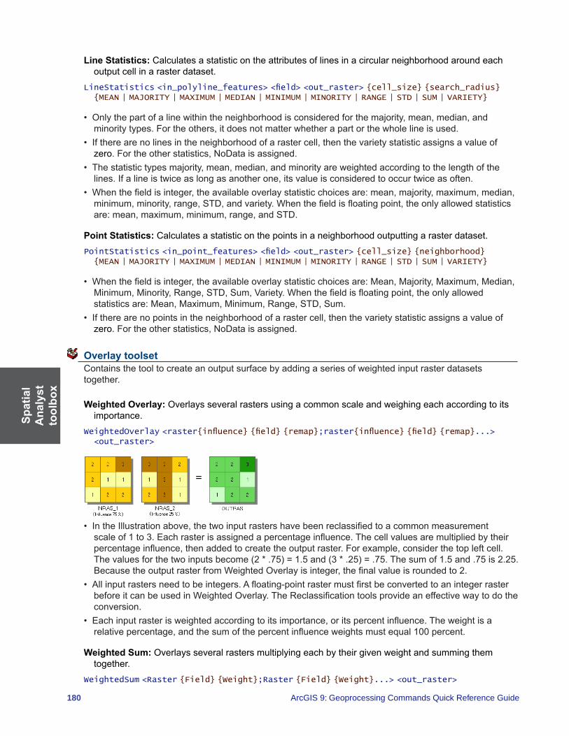
Spat
ial
Ana
lyst
to
olbo
x
180 ArcGIS 9: Geoprocessing Commands Quick Reference Guide
Line Statistics: Calculates a statistic on the attributes of lines in a circular neighborhood around each output cell in a raster dataset.
LineStatistics <in_polyline_features> <field> <out_raster> {cell_size} {search_radius} {MEAN | MAJORITY | MAXIMUM | MEDIAN | MINIMUM | MINORITY | RANGE | STD | SUM | VARIETY}
• Onlythepartofalinewithintheneighborhoodisconsideredforthemajority,mean,median,andminoritytypes.Fortheothers,itdoesnotmatterwhetherapartorthewholelineisused.
• Iftherearenolinesintheneighborhoodofarastercell,thenthevarietystatisticassignsavalueofzero.Fortheotherstatistics,NoDataisassigned.
• Thestatistictypesmajority,mean,median,andminorityareweightedaccordingtothelengthofthelines.Ifalineistwiceaslongasanotherone,itsvalueisconsideredtooccurtwiceasoften.
• Whenthefieldisinteger,theavailableoverlaystatisticchoicesare:mean,majority,maximum,median,minimum,minority,range,STD,andvariety.Whenthefieldisfloatingpoint,theonlyallowedstatisticsare:mean,maximum,minimum,range,andSTD.
Point Statistics: Calculates a statistic on the points in a neighborhood outputting a raster dataset.PointStatistics <in_point_features> <field> <out_raster> {cell_size} {neighborhood} {MEAN | MAJORITY | MAXIMUM | MEDIAN | MINIMUM | MINORITY | RANGE | STD | SUM | VARIETY}
• Whenthefieldisinteger,theavailableoverlaystatisticchoicesare:Mean,Majority,Maximum,Median,Minimum,Minority,Range,STD,Sum,Variety.Whenthefieldisfloatingpoint,theonlyallowedstatisticsare:Mean,Maximum,Minimum,Range,STD,Sum.
• Iftherearenopointsintheneighborhoodofarastercell,thenthevarietystatisticassignsavalueofzero.Fortheotherstatistics,NoDataisassigned.
Overlay toolset Contains the tool to create an output surface by adding a series of weighted input raster datasets together.
Weighted Overlay: Overlaysseveralrastersusingacommonscaleandweighingeachaccordingtoitsimportance.
WeightedOverlay <raster{influence} {field} {remap};raster{influence} {field} {remap}...> <out_raster>
• IntheIllustrationabove,thetwoinputrastershavebeenreclassifiedtoacommonmeasurementscaleof1to3.Eachrasterisassignedapercentageinfluence.Thecellvaluesaremultipliedbytheirpercentageinfluence,thenaddedtocreatetheoutputraster.Forexample,considerthetopleftcell.Thevaluesforthetwoinputsbecome(2*.75)=1.5and(3*.25)=.75.Thesumof1.5and.75is2.25.BecausetheoutputrasterfromWeightedOverlayisinteger,thefinalvalueisroundedto2.
• Allinputrastersneedtobeintegers.Afloating-pointrastermustfirstbeconvertedtoanintegerrasterbeforeitcanbeusedinWeightedOverlay.TheReclassificationtoolsprovideaneffectivewaytodotheconversion.
• Eachinputrasterisweightedaccordingtoitsimportance,oritspercentinfluence.Theweightisarelativepercentage,andthesumofthepercentinfluenceweightsmustequal100percent.
Weighted Sum:Overlaysseveralrastersmultiplyingeachbytheirgivenweightandsummingthemtogether.
WeightedSum <Raster {Field} {Weight};Raster {Field} {Weight}...> <out_raster>
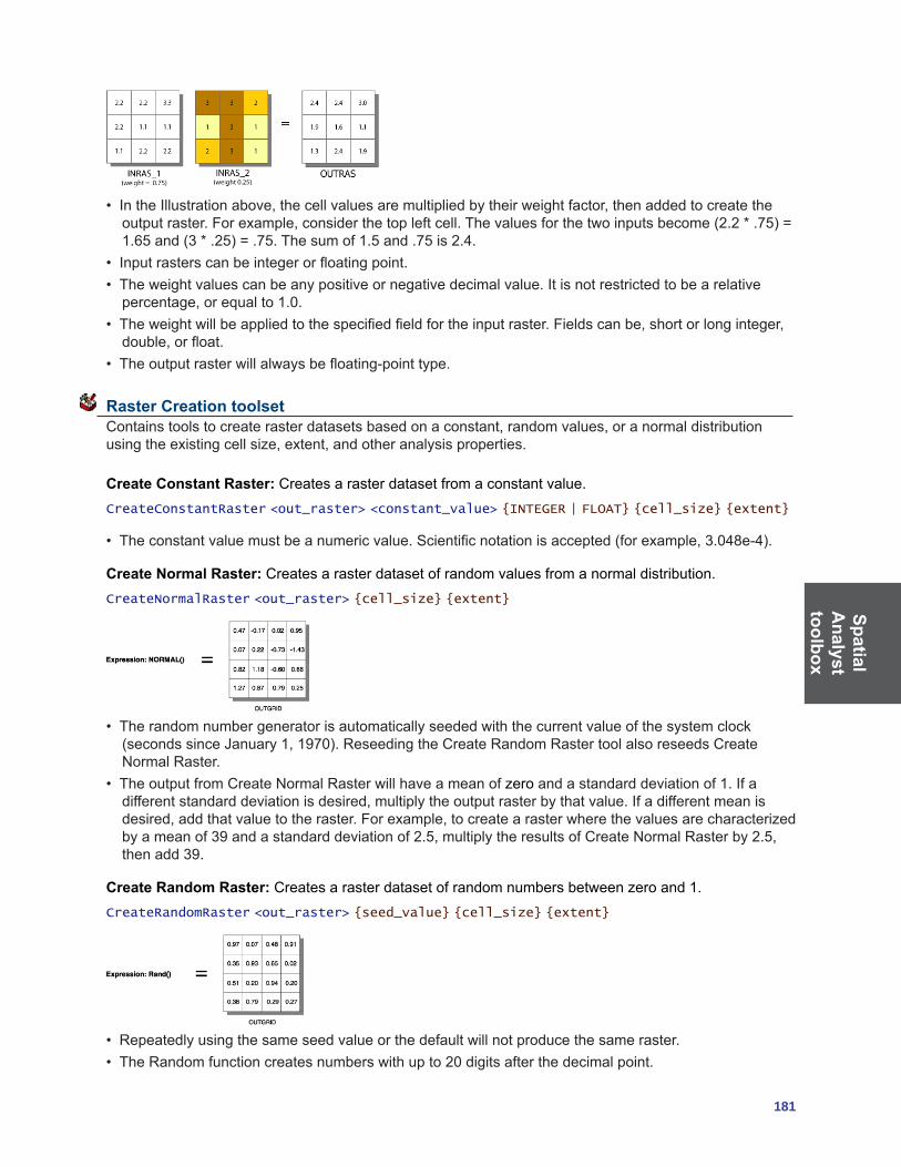
SpatialA
nalysttoolbox
181
• IntheIllustrationabove,thecellvaluesaremultipliedbytheirweightfactor,thenaddedtocreatetheoutputraster.Forexample,considerthetopleftcell.Thevaluesforthetwoinputsbecome(2.2*.75)=1.65and(3*.25)=.75.Thesumof1.5and.75is2.4.
• Inputrasterscanbeintegerorfloatingpoint.• Theweightvaluescanbeanypositiveornegativedecimalvalue.Itisnotrestrictedtobearelativepercentage,orequalto1.0.
• Theweightwillbeappliedtothespecifiedfieldfortheinputraster.Fieldscanbe,shortorlonginteger,double,orfloat.
• Theoutputrasterwillalwaysbefloating-pointtype.
Raster Creation toolset Containstoolstocreaterasterdatasetsbasedonaconstant,randomvalues,oranormaldistributionusingtheexistingcellsize,extent,andotheranalysisproperties.
Create Constant Raster: Creates a raster dataset from a constant value.CreateConstantRaster <out_raster> <constant_value> {INTEGER | FLOAT} {cell_size} {extent}
• Theconstantvaluemustbeanumericvalue.Scientificnotationisaccepted(forexample,3.048e-4).
Create Normal Raster: Creates a raster dataset of random values from a normal distribution.CreateNormalRaster <out_raster> {cell_size} {extent}
• Therandomnumbergeneratorisautomaticallyseededwiththecurrentvalueofthesystemclock(secondssinceJanuary1,1970).ReseedingtheCreateRandomRastertoolalsoreseedsCreateNormal Raster.
• TheoutputfromCreateNormalRasterwillhaveameanofzero and a standard deviation of 1. If a differentstandarddeviationisdesired,multiplytheoutputrasterbythatvalue.Ifadifferentmeanisdesired,addthatvaluetotheraster.Forexample,tocreatearasterwherethevaluesarecharacterizedbyameanof39andastandarddeviationof2.5,multiplytheresultsofCreateNormalRasterby2.5,then add 39.
Create Random Raster: Createsarasterdatasetofrandomnumbersbetweenzeroand1.CreateRandomRaster <out_raster> {seed_value} {cell_size} {extent}
• Repeatedlyusingthesameseedvalueorthedefaultwillnotproducethesameraster.• TheRandomfunctioncreatesnumberswithupto20digitsafterthedecimalpoint.
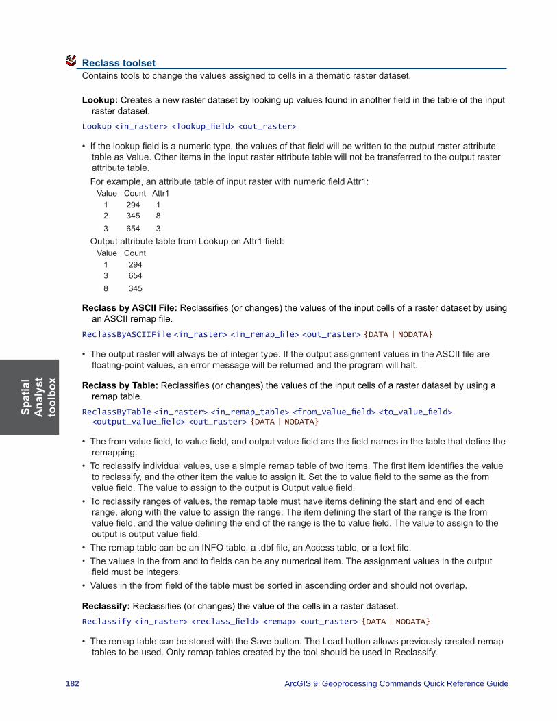
Spat
ial
Ana
lyst
to
olbo
x
182 ArcGIS 9: Geoprocessing Commands Quick Reference Guide
Reclass toolset Contains tools to change the values assigned to cells in a thematic raster dataset.
Lookup: Createsanewrasterdatasetbylookingupvaluesfoundinanotherfieldinthetableoftheinputraster dataset.
Lookup <in_raster> <lookup_field> <out_raster>
• Ifthelookupfieldisanumerictype,thevaluesofthatfieldwillbewrittentotheoutputrasterattributetableasValue.Otheritemsintheinputrasterattributetablewillnotbetransferredtotheoutputrasterattribute table.
Forexample,anattributetableofinputrasterwithnumericfieldAttr1:ValueCountAttr1 1 294 1 2 345 836543
OutputattributetablefromLookuponAttr1field:ValueCount 1 2943654 8 345
Reclass by ASCII File:Reclassifies(orchanges)thevaluesoftheinputcellsofarasterdatasetbyusinganASCIIremapfile.
ReclassByASCIIFile <in_raster> <in_remap_file> <out_raster> {DATA | NODATA}
• Theoutputrasterwillalwaysbeofintegertype.IftheoutputassignmentvaluesintheASCIIfilearefloating-pointvalues,anerrormessagewillbereturnedandtheprogramwillhalt.
Reclass by Table:Reclassifies(orchanges)thevaluesoftheinputcellsofarasterdatasetbyusingaremap table.
ReclassByTable <in_raster> <in_remap_table> <from_value_field> <to_value_field> <output_value_field> <out_raster> {DATA | NODATA}
• Thefromvaluefield,tovaluefield,andoutputvaluefieldarethefieldnamesinthetablethatdefinetheremapping.
• Toreclassifyindividualvalues,useasimpleremaptableoftwoitems.Thefirstitemidentifiesthevaluetoreclassify,andtheotheritemthevaluetoassignit.Setthetovaluefieldtothesameasthefromvaluefield.ThevaluetoassigntotheoutputisOutputvaluefield.
• Toreclassifyrangesofvalues,theremaptablemusthaveitemsdefiningthestartandendofeachrange,alongwiththevaluetoassigntherange.Theitemdefiningthestartoftherangeisthefromvaluefield,andthevaluedefiningtheendoftherangeisthetovaluefield.Thevaluetoassigntotheoutputisoutputvaluefield.
• TheremaptablecanbeanINFOtable,a.dbffile,anAccesstable,oratextfile.• Thevaluesinthefromandtofieldscanbeanynumericalitem.Theassignmentvaluesintheoutputfieldmustbeintegers.
• Valuesinthefromfieldofthetablemustbesortedinascendingorderandshouldnotoverlap.
Reclassify:Reclassifies(orchanges)thevalueofthecellsinarasterdataset.Reclassify <in_raster> <reclass_field> <remap> <out_raster> {DATA | NODATA}
• TheremaptablecanbestoredwiththeSavebutton.TheLoadbuttonallowspreviouslycreatedremaptablestobeused.OnlyremaptablescreatedbythetoolshouldbeusedinReclassify.
SpatialA
nalysttoolbox
183
• IfrunningtheReclassifytoolaspartofamodelwithinaModelBuilderwindow,runthetoolsbeforetheReclassifytoolinthemodelfirst.ThiswillallowthevaluesfortheinputrastertodisplayproperlyintheReclassificationdialogbox.
Slice:Slicesarangeofvaluesoftheinputcellsofarasterbyzonesofequalinterval,equalarea,orbynatural breaks.
Slice <in_raster> <out_raster> <number_zones> {EQUAL_INTERVAL | EQUAL_AREA | NATURAL_BREAKS} {base_output_zone}
• Ifamaskhasbeenset,thosecellsthathavebeenmaskedoutwillreceiveNoDataontheoutputsliceraster.
Solar Radiation toolset Contains tools to perform solar radiation analysis.
Area Solar Radiation: Derives incoming solar radiation from a raster surface.AreaSolarRadiation <in_surface_raster> <out_global_radiation_raster> {latitude} {sky_size} {time_configuration} {day_interval} {hour_interval} {NOINTERVAL | INTERVAL} {z_factor} {FROM_DEM | FLAT_SURFACE} {calculation_directions} {zenith_divisions} {azimuth_divisions} {UNIFORM_SKY | STANDARD_OVERCAST_SKY} {diffuse_proportion} {transmittivity} {out_direct_radiation_raster} {out_diffuse_radiation_raster} {out_direct_duration_raster}
• Becauseinsolationcalculationscanbetimeconsuming,itisimportanttobesureallparametersarecorrect.Calculationforalargedigitalelevationmodelcantakehours,andaverylargeDEMcouldtakedays.
• Theoutputradiationrasterswillalwaysbefloating-pointtypeandhaveunitsofwatthourspersquaremeter(WH/m2).Thedirectdurationrasteroutputwillbeintegerwithunithours.
Points Solar Radiation:Derivesincomingsolarradiationforspecificlocationsinapointfeatureclassorlocation table.
PointsSolarRadiation <in_surface_raster> <in_points_feature_or_table> <out_global_radiation_features> {height_offset} {latitude} {sky_size} {time_configuration} {day_interval} {hour_interval} {NOINTERVAL | INTERVAL} {z_factor} {FROM_DEM | FLAT_SURFACE | FROM_POINTS_TABLE} {calculation_directions} {zenith_divisions} {azimuth_divisions} {UNIFORM_SKY | STANDARD_OVERCAST_SKY} {diffuse_proportion} {transmittivity} {out_direct_radiation_features} {out_diffuse_radiation_features} {out_direct_duration_features}
• Theinputlocationscanbeafeatureclassortable.ThetablecanbeanINFOtable,a.dbffile,anAccesstable,oratexttablefile.
• Wheninputtinglocationsbytable,alistoflocationsmustbespecifiedwithanx,ycoordinate.• Formultiple-daytimeconfigurations,themaximumrangeofdaysisatotalofoneyear(365days,or366daysforleapyears).
• Forwithin-daytimeconfigurations,themaximumrangeoftimeisoneday(24hours).
Solar Radiation Graphics:Derivesrasterrepresentationsofahemisphericalviewshed,sunmap,andskymap,whichareusedinthecalculationofdirect,diffuse,andglobalsolarradiation.
SolarRadiationGraphics <in_surface_raster> <out_viewshed_raster> {in_points_feature_or_table} {sky_size} {height_offset} {calculation_directions} {latitude} {time_configuration} {day_interval} {hour_interval} {out_sunmap_raster} {zenith_divisions} {azimuth_divisions} {out_skymap_raster}

Spat
ial
Ana
lyst
to
olbo
x
184 ArcGIS 9: Geoprocessing Commands Quick Reference Guide
• Outputsarerasterrepresentationsandarenotmapsthatcorrespondtotheoutputsfromtheareaorpointsolarradiationanalysis.Rather,theyarerepresentationsofdirectionsinahemisphereofdirectionslookingupwardfromagivenlocation.Inahemisphericalprojection,thecenteristhezenith,theedgeofthecircular“map”isthehorizon,andtheanglerelativetothezenithisproportionaltotheradius.Hemisphericalprojectionsdonothaveageographiccoordinatesystemandhaveabottomleftcornerof(0,0).
• ItwouldnotbepracticaltostoreviewshedsforalllocationsinaDEM,sowheninputlocationsarenotspecified,asingleviewshediscreatedforthecenteroftheinputsurfaceraster.
• TheinputlocationstablecanbeanINFOtable,a.dbffile,anAccesstable,oratextfile.• Outputgraphicdisplayrastersdonothonorextentorcellsizeenvironmentsettings.• Oneortwosunmaprastersmaybegenerated,dependingonwhetherthetimeconfigurationincludes
overlapping sun positions throughout the year.
Surface toolset Containstoolstoanalyzethesurfaceoftheshapesrepresentedbytherastervalues.
Aspect:Identifiesthedownslopedirectionofthemaximumrateofchangeinvaluefromeachcelltoitsneighbors.
Aspect <in_raster> <out_raster>
• Aspectisthedirectionofthemaximumrateofchangeinthez-valuefromeachcellinarastersurface.• Aspectisexpressedinpositivedegreesfromzeroto359.9,measuredclockwisefromthenorth.• Cellsintheinputrasterofzeroslope(forexample,flat)areassignedanaspectof-1.
Contour: Creates contours or isolines from a raster dataset surface.Contour <in_raster> <out_polyline_features> <contour_interval> {base_contour} {z_factor}
• SmootherbutlessaccuratecontoursmaybeobtainedbyfirstperformingaNeighborhoodFocalStatistics operation with the mean option on the input raster.
• Abasecontourisused,forexample,whenyouwanttocreatecontoursevery15meters,startingat10meters.Here,10wouldbeusedforthebasecontour,and15wouldbethecontourinterval.Thevaluestobecontouredwouldbe10,25,40,55,andsoon.
• Specifyingabasecontourdoesnotpreventcontoursfrombeingcreatedaboveorbelowthatvalue.
Contour List: Creates contours or isolines based on a list of contour values.ContourList <in_raster> <out_polyline_features> <contour_values;contour_values...>
• SmootherbutlessaccuratecontoursmaybeobtainedbyfirstperformingaNeighborhoodFocalStatistics operation with the mean option on the input raster.
Contour With Barriers: Creates contours from a raster dataset surface using barrier features.ContourWithBarriers <in_raster> <out_contour_feature_class> {in_barrier_features} {POLYLINES | POLYGONS} {in_contour_values_file} {NO_EXPLICIT_VALUES_ONLY | EXPLICIT_VALUES_ONLY} {in_base_contour} {in_contour_interval} {in_indexed_contour_interval} {in_contour_list;in_contour_list...} {in_z_factor}
• Theinclusionofbarrierfeaturesallowsyoutoindependentlygeneratecontoursoneithersideofabarrier.
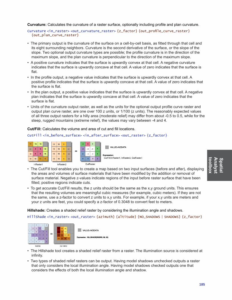
SpatialA
nalysttoolbox
185
Curvature: Calculatesthecurvatureofarastersurface,optionallyincludingprofileandplancurvature.Curvature <in_raster> <out_curvature_raster> {z_factor} {out_profile_curve_raster} {out_plan_curve_raster}
• Theprimaryoutputisthecurvatureofthesurfaceonacell-by-cellbasis,asfittedthroughthatcellanditseightsurroundingneighbors.Curvatureisthesecondderivativeofthesurface,ortheslopeoftheslope.Twooptionaloutputcurvaturetypesarepossible;theprofilecurvatureisinthedirectionofthemaximumslope,andtheplancurvatureisperpendiculartothedirectionofthemaximumslope.
• Apositivecurvatureindicatesthatthesurfaceisupwardlyconvexatthatcell.Anegativecurvatureindicatesthatthesurfaceisupwardlyconcaveatthatcell.Avalueofzeroindicatesthatthesurfaceisflat.
• Intheprofileoutput,anegativevalueindicatesthatthesurfaceisupwardlyconvexatthatcell.Apositiveprofileindicatesthatthesurfaceisupwardlyconcaveatthatcell.Avalueofzeroindicatesthatthesurfaceisflat.
• Intheplanoutput,apositivevalueindicatesthatthesurfaceisupwardlyconvexatthatcell.Anegativeplanindicatesthatthesurfaceisupwardlyconcaveatthatcell.Avalueofzeroindicatesthatthesurfaceisflat.
• Unitsofthecurvatureoutputraster,aswellastheunitsfortheoptionaloutputprofilecurverasterandoutputplancurveraster,areoneover100zunits,or1/100(zunits).Thereasonablyexpectedvaluesofallthreeoutputrastersforahillyarea(moderaterelief)maydifferfromabout-0.5to0.5,whileforthesteep,ruggedmountains(extremerelief),thevaluesmayvarybetween-4and4.
Cut/Fill:Calculatesthevolumeandareaofcutandfilllocations.CutFill <in_before_surface> <in_after_surface> <out_raster> {z_factor}
• TheCut/Filltoolenablesyoutocreateamapbasedontwoinputsurfaces(beforeandafter),displayingtheareasandvolumesofsurfacematerialsthathavebeenmodifiedbytheadditionorremovalofsurfacematerial.Negativez-valuesindicateregionsoftheinputbeforerastersurfacethathavebeenfilled;positiveregionsindicatecuts.
• TogetaccurateCut/Fillresults,thezunitsshouldbethesameasthex,ygroundunits.Thisensuresthattheresultingvolumesaremeaningfulcubicmeasures(forexample,cubicmeters).Iftheyarenotthesame,useaz-factortoconvertzunitstox,yunits.Forexample,ifyourx,yunitsaremetersandyourzunitsarefeet,youcouldspecifyaz-factorof0.3048toconvertfeettometers.
Hillshade: Creates a shaded relief raster by considering the illumination angle and shadows.HillShade <in_raster> <out_raster> {azimuth} {altitude} {NO_SHADOWS | SHADOWS} {z_factor}
• TheHillshadetoolcreatesashadedreliefrasterfromaraster.Theilluminationsourceisconsideredatinfinity.
• Twotypesofshadedreliefrasterscanbeoutput.Havingmodelshadowsuncheckedoutputsarasterthatonlyconsidersthelocalilluminationangle.Havingmodelshadowscheckedoutputsonethatconsiders the effects of both the local illumination angle and shadow.

Spat
ial
Ana
lyst
to
olbo
x
186 ArcGIS 9: Geoprocessing Commands Quick Reference Guide
Observer Points:Identifiesexactlywhichobserverpointsarevisiblefromeachsurfacelocation.ObserverPoints <in_raster> <in_observer_point_features> <out_raster> {z_factor} {FLAT_EARTH | CURVED_EARTH} {refractivity_coefficient}
• Thevisibilityofeachcellcenterisdeterminedbycomparingthealtitudeangletothecellcenterwiththealtitudeangletothelocalhorizon.Thelocalhorizoniscomputedbyconsideringtheinterveningterrainbetweenthepointofobservationandthecurrentcellcenter.Ifthepointliesabovethelocalhorizon,itis considered visible.
Slope:Identifiestherateofmaximumchangeinz-valuefromeachcell.Slope <in_raster> <out_raster> {DEGREE | PERCENT_RISE} {z_factor}
• Slopeistherateofmaximumchangeinz-valuefromeachcell.• Theuseofaz-factorisessentialforcorrectslopecalculationswhenthesurfacezunitsareexpressedinunitsdifferentfromthegroundx,yunits.
• Degreeofslopeisavaluebetweenzero and 90.
Viewshed: Derives the raster dataset surface locations visible to a set of observation points.Viewshed <in_raster> <in_observer_features> <out_raster> {z_factor} {FLAT_EARTH | CURVED_EARTH} {refractivity_coefficient}
• Thevisibilityofeachcellcenterisdeterminedbycomparingthealtitudeangletothecellcenterwiththealtitudeangletothelocalhorizon.Thelocalhorizoniscomputedbyconsideringtheinterveningterrainbetweenthepointofobservationandthecurrentcellcenter.Ifthepointliesabovethelocalhorizon,itis considered visible.
Zonal toolset Containstoolsthatcanbeappliedtothezoneswithintherasterdataset.
Tabulate Area: Calculates cross-tabulated areas between two datasets.TabulateArea <in_zone_data> <zone_field> <in_class_data> <class_field> <out_table> {processing_cell_size}
• Zonesarecreatedbyidenticalintegervalues.Iftheinputisaraster,itmustbeinteger.Iftheinputisafeatureclass,theZonefieldmustbeinteger.
• Therewillbeafieldintheoutputtableforeachuniquevalueoftheinputrasterorfeaturezonedata.• Therewillbearecordintheoutputtableforeachuniquevalueoftheinputrasterorfeatureclassdata.• Eachrecordintheoutputtablewillstoretheareaofeachclasswithineachzone.• Ifapointorlinedatasetisusedastheclassdata,thentheareaintersectedbythosefeatureswillbe
reported.
Zonal Fill: Fillszonesinadatasetusingtheminimumcellvaluefromanotherrasterdatasetalongthezoneboundary.
ZonalFill <in_zone_raster> <in_weight_raster> <out_raster>
• ZonalFillcanbeusedtofillsinkstotheminimumelevationoftheirwatershedboundary.Thisisastepindeterminingthedepthofsinksbeforefillingtocreateadepressionlessdigitalelevationmodel.
• Theinputzonerastermustbeinteger.

SpatialA
nalysttoolbox
187
Zonal Geometry: Calculatesforeachzoneinadatasetthespecifiedgeometrymeasure(area,perimeter,thickness,orthecharacteristicsofellipse).
ZonalGeometry <in_zone_data> <zone_field> <out_raster> {AREA | PERIMETER | THICKNESS | CENTROID} {cell_size}
• Zonesarecreatedbyidenticalintegervalues.Iftheinputisaraster,itmustbeinteger.Iftheinputisafeatureclass,thezonefieldmustbeinteger.
• Ifthezonedatasetisafeaturedataset,itisrecommendedthatyouensuretheextentandsnaprastersare set appropriately in the environment settings or raster settings. This will ensure that the results of the vector-to-raster conversion will align properly with the value raster.
Zonal Geometry as Table:Calculatesforeachzoneinadatasetthegeometrymeasures—forexample,area,perimeter,thickness,andthecharacteristicsofellipse—andreportstheresultsasatable.
ZonalGeometryAsTable <in_zone_data> <zone_field> <out_table> {processing_cell_size}
• Zonesarecreatedbyidenticalintegervalues.Ifthezoneinputisaraster,itmustbeinteger.Ifthezoneinputisafeatureclass,thezonefieldmustbeinteger.
• Iftheinputrasterorfeaturezonedataisafeaturedataset,acellsizemustbesetineitherthedialogboxortheenvironmentsettings.Toalignthefeaturedatasettothevalueraster,itisrecommendedthatthe extent and snap rasters are set appropriately in the environment settings and raster settings.
• Alltheresultsintheoutputtablearepresentedinmapunits.OnlythevaluesoftheORIENTATIONitemareindegrees,withapossiblerangeofzeroto180.TheORIENTATIONisdefinedasananglebetween the x-axis and the major axis of the ellipse. The values of the orientation angle increase counterclockwise,startingfromzerointheeast(horizontal,totheright)andgoingthrough90whenthemajor axis is vertical.
• AnexampleoftheZonalGeometryAsTableonthefollowinginput:
This would populate the output table as follows:VALUE AREA PERIMETER THICKNESS XCENTROID YCENTROID MAJORAXIS MINORAXIS ORIENTATION
0 5.0 14.0 0.5 2.300 2.100 2.338 0.681 60.710
1 5.0 14.0 0.5 1.900 2.100 2.668 0.596 126.061
2 6.0 8.0 0.5 3.167 2.167 1.286 0.743 130.00
4 2.0 6.0 0.5 0.500 1.000 1.128 0.564 90.00
Zonal Statistics: Calculatesastatisticonvaluesofarasterwithinthezonesofanotherdataset.ZonalStatistics <in_zone_data> <zone_field> <in_value_raster> <out_raster> {MEAN | MAJORITY | MAXIMUM | MEDIAN | MINIMUM | MINORITY | RANGE | STD | SUM | VARIETY} {DATA | NODATA}
• Theinputvaluerastercanbeeitherintegerorfloatingpoint.However,whenitisoffloating-pointtype,thezonalcalculationsformajority,median,minority,andvarietyarenotavailable.
• Formajorityandminority,whenthereisatie,theoutputforallcelllocationsinthezoneareassignedthe lowest of the tied values.
Zonal Statistics as Table: Summarizesvaluesofarasterdatasetwithinthezonesofanotherdatasetand reports the results to a table.
ZonalStatisticsAsTable <in_zone_data> <zone_field> <in_value_raster> <out_table> {DATA | NODATA}
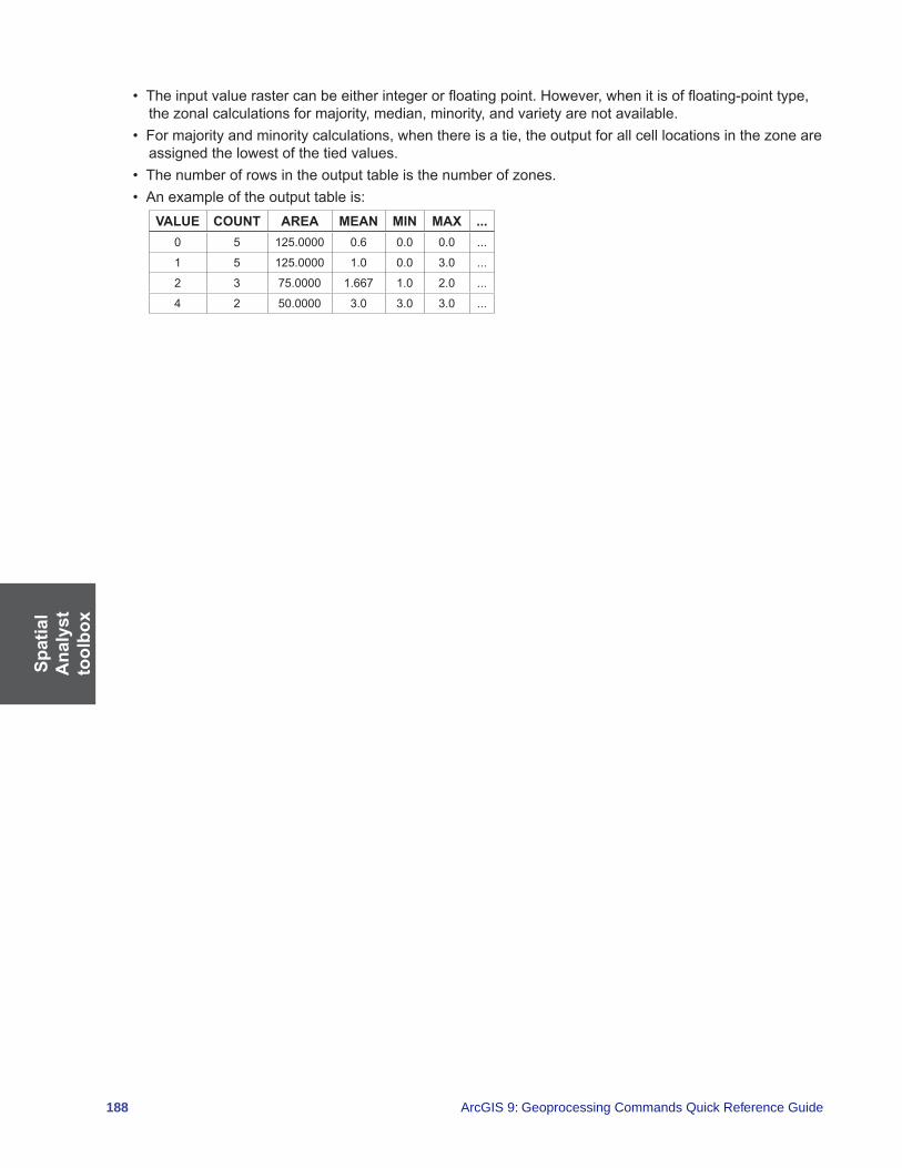
Spat
ial
Ana
lyst
to
olbo
x
188 ArcGIS 9: Geoprocessing Commands Quick Reference Guide
• Theinputvaluerastercanbeeitherintegerorfloatingpoint.However,whenitisoffloating-pointtype,thezonalcalculationsformajority,median,minority,andvarietyarenotavailable.
• Formajorityandminoritycalculations,whenthereisatie,theoutputforallcelllocationsinthezoneareassigned the lowest of the tied values.
• Thenumberofrowsintheoutputtableisthenumberofzones.• Anexampleoftheoutputtableis:
VALUE COUNT AREA MEAN MIN MAX ...0 5 125.0000 0.6 0.0 0.0 ...
1 5 125.0000 1.0 0.0 3.0 ...
2 3 75.0000 1.667 1.0 2.0 ...
4 2 50.0000 3.0 3.0 3.0 ...

TrackingA
nalysttoolbox
189
Tracking Analyst toolbox This toolbox provides tools for preparing and loading temporal data into an ArcGIS application.
Concatenate Date and Time Fields: Concatenatestwoseparatedateandtimefieldsintoanewfieldthat is added to the same feature dataset.
ConcatenateDateAndTimeFields <feature_class> <date_field> <time_field> <output_field>
• Inputvaluesmustbetexttype.• Thistooladdsanewtextfieldtotheinputfeaturedataset.• Ifyouareworkingwithashapefilethatcontainsadatefieldwiththedateonly(forexample,03/09/2006),youmustcalculatetheinformationintoanewfieldthatisoftypetextbeforeyoucanconcatenateitwithatimefield.
Make Tracking Layer: Adds a feature dataset as a new tracking layer to your ArcMap session.MakeTrackingLayer <feature_class> <date_field> {track_field} <output_name> {H:MM:SS TT | HH:MM:SS TT | H:MM:SS | HH:MM:SS} {M/D/YYYY | M/D/YY | MM/DD/YY | MM/DD/YYYY | YY/MM/DD | YYYY-MM-DD | DD-MMM-YY} {AM} {PM}
• Thedate_fieldmustcontainboththedateandtimefortheevent.• Ifthedatefieldisstringtype,thenyoumustspecifytheformatofdateandtime.

Index
191
indexnumbers3D Analyst toolbox ....................................................... 1093D ASCII file
converting to feature class .......................................... 1093D files
importing .................................................................... 1093D layer
converting to feature class .......................................... 109
AAbs command ............................................................... 160Absolute value. See Abs commandACos command ............................................................. 173ACosH command .......................................................... 173AddCADFields command ............................................... 19AddCodedValueToDomain command ............................ 49AddColormap command ................................................. 77AddFeatureClassToTerrain command ........................... 123AddFeatureClassToTopology command ......................... 81AddField command ......................................................... 57AddFieldToAnalysisLayer command ........................... 133AddGlobalIDs command ................................................ 63AddIndex command ........................................................ 64Adding. See also Plus command
attribute index............................................................... 64CAD fields .................................................................... 19coded value to domain ................................................. 39color maps .................................................................... 77indexes.......................................................................... 64items ............................................................................. 78joins . ............................................................................ 65rules to topology ........................................................... 81spatial indexes .............................................................. 64subtypes ........................................................................ 79x,y coordinates ............................................................. 12
AddLocations command ............................................... 133AddRepresentation command ......................................... 85Address
geocoding ..................................................................... 85locator
creating ......................................................................86deleting ......................................................................86rebuilding ..................................................................86
AddressBuild. See RebuildGeocodingIndex commandAddressCreate. See CreateAddressLocator commandAddressMatch. See GeocodeAddresses commandAddressParse. See StandardizeAddresses commandAddRouteMeasure. See LocateFeaturesAlongRoutes
commandAddSubtype command .................................................... 79AddTerrainPoints command ......................................... 124
AddTerrainPyramidLevel command ............................. 124AddXY command ............................................................. 2Adjust. See Transform commandADRGGrid. See CopyRaster commandAdvanced Tiger Conversion. See TigerTool commandAggregate
command .................................................................... 147Aggregate Polygons. See AreaAggregate commandAggregatePolygons command ........................................ 79Analysis
toolbox.......................................................................... 76toolset ......................................................................... 133
Analyze command .......................................................... 80Analyzing
hot spots ....................................................................... 34Analyzing Patterns toolset .............................................. 31And
bitwise ........................................................................ 165Boolean ...................................................................... 167combinatorial.............................................................. 168
Annotationimporting from CAD .................................................... 21importing from coverage .............................................. 65
Append command ........................................................... 35ApplySymbologyFromLayer command ......................... 66ArcDXF. See ExportCAD commandArcEditor
licensing ......................................................................... 2ArcIGDS. See ExportCAD commandArcInfo
licensing ....................................................................... 47ArcInfo workspace
creating ......................................................................... 84ArcSection. See CreateRoutes commandArcShape. See FeatureClassToShapefile commandArcTiger. See TigerArc command. See TigerTool
commandArcTIN. See Editing: TINsAreaAggregate. See AggregatePolygons commandAreaSolarRadiation command ...................................... 183Arguments ....................................................................... 57ASCII
converting to raster ..................................................... 109Ascii3DToFeatureClass command .................................. 49ASCIIGrid. See ASCII: converting to rasterASin command .............................................................. 173ASinH command ........................................................... 174Aspect command ................................................... 121, 184ATan2 command ........................................................... 174ATan command ............................................................. 174ATanH command .......................................................... 175Attributes
joining tables ................................................................ 85
Inde
x
192 ArcGIS 9: Geoprocessing Commands Quick Reference Guide
BBand Collection Statistics. See BandCollectionStats
commandBandCollectionStats command ..................................... 176Base 2. See Exp2 command. See also Log2 commandBase 10. See Exp10 command. See Log10 commandBase e. See Exp commandBasic Tiger Conversion. See TigerArc: commandBasin command ............................................................. 151Batch
projecting...................................................................... 69BatchBuildPyramids command ...................................... 77BatchCalculateStatistics command ................................. 77BatchProject command ................................................... 69Bitwise
And 165Complement. See BitwiseNot commandExclusive Or ............167. See also BitwiseXOr commandleft shift ...................................................................... 165Not 166Or 166right shift .................................................................... 166toolset ......................................................................... 165
BitwiseAnd command ................................................... 165BitwiseLeftShift command ........................................... 165BitwiseNot command .................................................... 166BitwiseOr command ..................................................... 166BitwiseRightShift command ......................................... 166BitwiseXOr command .................................................. 167BlockMajority. See BlockStatistics commandBlockMax. See BlockStatistics commandBlockMean. See BlockStatistics commandBlockMedian. See BlockStatistics commandBlockMin. See BlockStatistics commandBlockMinority. See BlockStatistics commandBlockRange. See BlockStatistics commandBlockStatistics command .............................................. 179BlockStd. See BlockStatistics commandBlockSum. See BlockStatistics commandBlockVariety. See BlockStatistics command.
See BlockStatistics commandBoolean
And . ........................................................................... 167Complement. See BooleanNot commandExclusive Or ............................................................... 168Not .. ........................................................................... 167or ....... ........................................................................ 168
BooleanAnd command .................................................. 167BooleanNot command .................................................. 167BooleanOr command .................................................... 168BooleanXOr command ................................................. 168BoundaryClean command ............................................. 147Buffer
command .................................................................. 8, 42using multiple rings ........................................................ 9
Build command ............................................................... 38Building
pyramids ....................................................................... 77raster attribute tables .................................................... 77
BuildNetwork command ............................................... 135BuildPyramids command ................................................ 77BuildRasterAttributeTable command ............................. 77BuildSta. See CellStatistics commandBuildTerrain command ................................................. 124
CCache
clearing ......................................................................... 46creating for Globe Server ............................................. 94creating for Map Server ......................................... 93, 94deleting for Globe Server ............................................. 93deleting for Map Server ............................................... 93tiling scheme ................................................................ 94
Cachingtoolset ........................................................................... 93
CADimporting ...................................................................... 51importing annotation
.............................................................................21CalculateAreas command ............................................. 104CalculateDistanceBand command ................................ 104CalculateEndDate command ........................................... 70CalculateField command ................................................ 59CalculateGeodesicAngle command ................................ 11CalculateLineCaps command ......................................... 51CalculateLocationFields command ............................... 133CalculateLocations command ....................................... 133CalculatePolygonMainAngle command ......................... 63CalculateRepresentationRule command ......................... 70CalculateStatistics command .......................................... 77CalculateValue command ................................................ 87Calculating
kernel density ............................................................. 140spatial grid index .......................................................... 64
CAnd. See CombinatorialAnd commandCell groupings
using isodata clustering .............................................. 178Cells
get value ....................................................................... 78CellStatistics command ................................................. 157Centerline
creating ......................................................................... 47CentroidLabels. See FeatureToPoint commandChangePrivileges command ............................................ 80ChangeTerrainReferenceScale command ..................... 124CheckGeometry command .............................................. 47Checking in
from Delta geodatabases .............................................. 36to ArcSDE .................................................................... 46
ClassProb. See ClassProbability command

Index
193
ClassProbability command ........................................... 176ClassSig. See CreateSignatures commandCleaning
boundaries .................................................................. 147ClearWorkspaceCache command .......................................Clip command ................................................................. 51Cluster and outlier analysis ........................................... 103Clustering
high/low........................................................................ 35ClustersOutliers command .............................................. 70ClustersOutliersRendered command ............................ 103Cluster tolerance
setting ........................................................................... 82CollapseDualLinesToCenterline command .................... 17CollapseDualLineToCenterline command ..........................CollectEventsRendered command ................................ 103Color maps
adding ........................................................................... 77deleting ......................................................................... 78
Combinatorialand .. ........................................................................... 168exclusive or ................................................................ 169or ..... .......................................................................... 169
CombinatorialAnd command ........................................ 168CombinatorialOr command .......................................... 169CombinatorialXOr command ........................................ 169Combine command ....................................................... 157Combining features. See Append commandCompact command ......................................................... 45CompareReplicaSchema command ................................ 45Comparing
features ......................................................................... 45files . ............................................................................. 46rasters ...............................................................................tables ............................................................................ 41TINs ............................................................................. 46
CompositeBands command ............................................ 75Composite Features toolset ............................................. 58ConcatenateDateAndTimeFields command ................. 189Con command ............................................................... 139Conditional toolset ........................................................ 139Conflicts
finding ........................................................................ 126Contour command ...............................................................Contours
creating ....................................................................... 184with barriers ................................................................. 59
ContourWithBarriers command ...................................... 53Conversion
toolbox........................................................................ 137toolset ..................................................................... 59, 34
ConvertDiagram command ............................................. 34ConvertImage. See CopyRaster commandConverting
to feature class .............................................................. 34to shapefile ................................................................... 76
ConvertRemap. See ReclassByASCIIFile commandConvertSpatialWeightsMatrixToTable command ......... 105Coordinates
adding x,y ..................................................................... 76Copy command ............................................................... 28CopyFeatures command .................................................. 32Copying
feature classes............................................................... 33feature datasets ............................................................. 42features ......................................................................... 33raster catalog items ....................................................... 72rows in a table .............................................................. 80tables ............................................................................ 42
CopyRasterCatalogItems command ................................ 72CopyRaster command ..................................................... 73CopyRows command ...................................................... 80COr. See CombinatorialOr commandCorridor command ........................................................ 175Cos command .................................................................. 42CosH command ............................................................. 175Cost
calculating least accumulative distance ..................... 142least accumulative ...................................................... 142least accumulative distance
path ..........................................................................142least accumulative path
define neighbor cell .................................................141least accumulative source ........................................... 144
CostAllocation command .............................................. 141CostBackLink command ............................................... 141CostDistance command ................................................ 142CostPath command ....................................................... 142Counting
table rows. See GetCount commandCountRenderer command ............................................. 103Coverages
creating ......................................................................... 85erasing .......................................................................... 19exporting as text file ..................................................... 80generating topology ...................................................... 66importing from DLG .................................................... 50importing from S57 ...................................................... 36importing from SDTS .................................................. 51importing from VPF ..................................................... 80projecting...................................................................... 51setting tolerances .......................................................... 80toolbox.......................................................................... 43updating ........................................................................ 89updating attribute table and topology ...............................
CreateAddressLocator command ........................................CreateArcInfoWorkspace command ............................... 84CreateCADXData command ........................................ 137Create command ........................................................... 181CreateConstantRaster command ..................................... 52CreateCustomGeoTransformation command ................. 68CreateDiagram command ............................................... 93
Inde
x
194 ArcGIS 9: Geoprocessing Commands Quick Reference Guide
CreateDomain command ....................................................CreateFeatureClass command ......................................... 75CreateFeatureDataset command ..................................... 84CreateFishnet command .................................................. 48CreateFolder command ................................................... 84CreateLabels command ................................................... 11CreateMapServerCache command .................................. 67CreateMobileBasemap command ................................. 181CreateNormalRaster command ....................................... 76CreateOrthoCorrectedRasterDataset command .............. 76CreatePersonalGDB command ....................................... 84CreateRelationshipClass command ................................ 78CreateReplica command ............................................... 137CreateReplicaFootPrints command .............................. 123CreateReplicaFromServer command .............................. 80CreateRoutes command ................................................ 124CreateSchematicFolder command ................................ 177CreateSignatures command ............................................ 66CreateSpatialReference command .................................. 69CreateTable command..................................................... 80CreateTerrain command ................................................ 124CreateThiessenPolygons command .................................. 8CreateTIN command ..................................................... 125CreateTopology command .............................................. 82CreateTurnFeatureClass command .....................................CreateUnderpass command ................................................CreateVersion command ................................................. 83CreateWorkspace. See CreateArcInfoWorkspace commandCreating
ArcInfo workspaces ..................................................... 84CAD x data ................................................................... 79multiband raster datasets .............................................. 75personal geodatabases .................................................. 84spatial references .......................................................... 69table to relationship classes .......................................... 79
CuldeSacMasks command ............................................ 184CXOr. See CombinatorialXOr command
dDarcyFlow command .................................................... 149DarcyVelocity command ............................................... 150Data
compressing.................................................................. 58selecting........................................................................ 61
Database toolset .............................................................. 46Data Comparison toolset ................................................. 45Data Interoperability toolbox ........................................ 129Data Management toolbox .............................................. 34Data Management toolset ............................................... 45Datasets
deleting ......................................................................... 60renaming ....................................................................... 58uncompressing.............................................................. 40
DBaseInfo. See TableToGeodatabase commandDBMSInfo. See TableToGeodatabase commandDeautomateGeocodingIndexes command ...................... 85
DecimateTinNodes command ....................................... 126DefineProjection command ............................................. 85DeleteAddressLocator command .................................... 50DeleteCodedValueFromDomain command .................... 73DeleteColormap command ............................................. 78Delete command ............................................................. 60DeleteDomain command ................................................ 53DeleteFeatures command ................................................ 54DeleteField command ..................................................... 58DeleteGlobeServerCache command ............................... 93DeleteMapServerCache command .................................. 73DeleteRasterAttributeTable command ............................ 78DeleteRasterCatalogItems command .............................. 73DeleteRows command .................................................... 80DeleteVersion command ................................................. 83Deleting
coded values from domains .......................................... 59domains ........................................................................ 59feature classes............................................................... 60feature datasets ............................................................. 60features ......................................................................... 54fields in a table ............................................................. 58geodatabase versions .................................................... 83items in a raster catalog ................................................ 72rows in a table .............................................................. 80tables ............................................................................ 60
DelineateTinDataArea command .................................. 125DEM
converting to raster ..................................................... 155DEMGrid. See DEM: converting to rasterDEMLattice. See DEM: converting to rasterDendrogram command .................................................. 177Density
calculating kernel ....................................................... 140calculating using line features .................................... 140calculating using point features .................................. 140toolset ......................................................................... 140
DetectGraphicConflict command .................................... 37DFADArc. See Feature class: converting to coverageDiagrams
converting ..................................................................... 47creating ....................................................................... 137updating ...................................................................... 137Updating ..................................................................... 137
Diff command ............................................................... 169DirectionalDistribution command .................................. 99DirectionalMean command ........................................... 133Directions command ....................................................... 87Disconnected Editing toolset .......................................... 87DisperseMarkers command ............................................ 33Dissolve command .......................................................... 48DissolveRouteEvents command ................................... 118Dissolving
route events .................................................................. 50Distance toolset ............................................................. 141Distributed Geodatabase toolset ..................................... 50
Index
195
Divide command ............. 50, 160. See also Mod commandDLG
importing to coverage .................................................. 39DLGArc command .......................................................... 49Domain
creating ......................................................................... 39creating from table ....................................................... 51deleting ......................................................................... 39removing from field...................................................... 12
Drainage. See Hydrology toolsetDropIndex command. See RemoveIndex commandDTEDGrid. See CopyRaster commandDXFArc. See ImportCAD commandDXFINFO. See ImportCAD command
eEditing
TINs ........................................................................... 126EditSig. See EditSignatures commandEditSignatures command .............................................. 177EditTin command .......................................................... 126Eliminate command .................................................. 37, 62Ellipse .............................................................................. 2Envelopes
creating polygons from ................................................ 54EqualityTest. See EqualTo commandEqualTo command ........................................................ 170EqualToFrequency command ....................................... 158Erase command ........................................................... 6, 28ESRI Metadata Translator ............................................... 18ESRITranslator command ............................................... 18ETAKArc. See FeatureClassToCoverage commandEucAllocation command ............................................... 143EucDirection command ................................................ 143EucDistance command .................................................. 143Euclidean
allocating ............ 143. See also EucAllocation commanddirection................143. See also EucDirection commanddistance ..................143. See also EucDistance command
EventArc. See MakeRouteEventLayer commandEventPoint. See MakeRouteEventLayer commandEvents
dissolving for routes ..................................................... 88EventTransform. See TransformRouteEvents commandExclusive Or
bitwise ........................................................................ 167Boolean ...................................................................... 169combinatorial.............................................................. 161
Exp2 command ............................................................. 161Exp10 command ........................................................... 147Expand command .......................................................... 160Exp command ............................................................... 161Exponential. See Exp command
base 2 .......................................................................... 161base 10 ........................................................................ 160base e .......................................................................... 161
ExportAcknowledgementMessage command ................. 48ExportCAD command .................................................... 31Export command ............................................................. 48Exporting
feature attribute to ASCII ........................................... 105to CAD ......................................................................... 47to Delta geodatabase .................................................... 48to interchange file ......................................................... 32to VPF .......................................................................... 72
ExportRasterCatalogPaths command .............................. 73ExportRasterWorldFile command................................... 78ExportToDelta command ................................................ 48ExportXYv command.................................................... 105ExtractByAttributes command ...................................... 145ExtractByCircle command ............................................ 145ExtractByMask command ............................................. 146ExtractByPoints command ............................................ 145ExtractByPolygon command ........................................ 146ExtractByRectangle command ...................................... 145Extraction toolset ............................................................ 75Extract toolset ............................................................... 146ExtractValuesToPoints command ................................. 125
FFeature class
adding to terrain ......................................................... 123combining ..................................................................... 59comparing ..................................................................... 20converting to coverage ................................................. 20converting to feature class ............................................ 20converting to shapefile ................................................. 20creating ........................................................................... 6intersecting ................................................................... 78remove from topology .................................................. 82toolset ............................................................................. 7updating attributes and geometry ................................. 19
FeatureClassToCoverage command ................................ 20FeatureClassToFeatureClass command .......................... 20FeatureclassToShapefile command ................................. 25FeatureOutlineMasks command ................................... 101Features
buffering ....................................................................... 22center of concentration ............................................... 100centrally located ........................................................... 99concentration or dispersion ........................................ 100converting to raster ....................................................... 23copying ........................................................................... 6deleting ......................................................................... 54dissolving ..................................................................... 62eliminating.................................................................... 62erasing .......................................................................... 52extracting ........................................................................ 7locating along routes .................................................... 54toolset ........................................................................... 53unioning........................................................................ 67
FeatureToLine command ................................................ 54

Inde
x
196 ArcGIS 9: Geoprocessing Commands Quick Reference Guide
FeatureToNetCDF command .......................................... 22Feature toolset ................................................................. 69FeatureToPoint command ............................................... 56FeatureToPolygon command .......................................... 55FeatureToRaster command ............................................. 23FeatureVerticesToPoints command ................................. 57Fields
adding ........................................................................... 57assigning default to ...................................................... 57calculating .................................................................... 37joining .......................................................................... 65
FileCompare command ................................................... 67Fill command ................................................................ 152Filter command ............................................................. 179FindConflicts command .................................................. 23Float
command ............................................................ 119, 161convert to raster .......................................................... 181
FloatGrid. See FloatToRaster commandFlow. See DarcyFlow commandFlowAccumulation command ....................................... 152FlowDirection command .............................................. 152FlowLength command .................................................. 153FMod. See Mod commandFocalFlow command ..................................................... 179FocalMajority. See FocalStatistics commandFocalMax. See FocalStatistics commandFocalMean. See FocalStatistics commandFocalMedian. See FocalStatistics commandFocalMin. See FocalStatistics commandFocalMinority. See FocalStatistics commandFocalRange. See FocalStatistics commandFocalStatistics command .............................................. 179FocalStd. See FocalStatistics commandFocalSum. See FocalStatistics commandFocalVariety. See FocalStatistics commandFrom Feature Class toolset ............................................ 109From File toolset ........................................................... 109From Raster toolset ....................................................... 110From Terrain toolset ...................................................... 111From TIN toolset ........................................................... 111Functional Surface toolset ............................................. 114
GGACalculateZValue command ..................................... 131GACreateGeostatisticalLayer command ...................... 131GAGetModelParameter command ................................ 132GALayerToContour command ..................................... 131GALayerToGrid command ........................................... 131GALayerToPoints command ........................................ 131GAMovingWindowKriging command ......................... 132GANeighborhoodSelection command .......................... 132GASemivariogramSensitivity command ...................... 132GASetModelParameter command ................................ 132GaussianGeostatisticalSimulations command .............. 131Generalization toolset ............................................. 58, 147
Generalize. See Line: simplification. See Lines: simplifying
General toolset ................................................................ 59Generate command ........................................................... 8GenerateGlobeServerCache command ........................... 94GenerateMapServerCache command .............................. 89GenerateMapServerCacheTilingScheme command ....... 85GenerateMobileServiceCache command ...................... 102GenerateNearTable command ....................................... 102GenerateNetworkSpatialWeights command ................. 101GenerateSpatialWeightsMatrix command .................... 101GeocodeAddresses command ......................................... 86Geocoding
addresses ...................................................................... 81deautomating indexes ................................................... 53index
rebuilding ..................................................................86toolbox.......................................................................... 11
Geodatabasecreating ......................................................................... 84
Geostatistical Analyst toolbox ...................................... 131Geostatistical layer
converting to contours ................................................ 131converting to grid ....................................................... 131converting to points .................................................... 131creating ....................................................................... 131
GreaterThan command .................................................. 170GreaterThanEqual command ........................................ 170GreaterThanFrequency command ................................. 158GridASCII. See RasterToASCII commandGridClip. See ExtractByRectangle commandGridComposite. See CompositeBands commandGridFlip. See Flip commandGridFloat. See RasterToFloat commandGridImage. See CopyRaster commandGridLine. See RasterToPolyline commandGridLineShape. See RasterToPolyline commandGridMirror. See MirrorGridPoint. See RasterToPoint commandGridPointShape. See RasterToPoint commandGridPoly. See RasterToPolygon commandGridRotate. See Rotate commandGridShape. See RasterToPolygon commandGridShift. See Shift commandGridWarp. See Warp commandGroundwater
calculating steady flow ............................................... 149dispersion of point ...................................................... 151toolset ......................................................................... 149
hHDF files
working with ................................................................ 76HighestPosition command ............................................ 158HighLowClustering command ........................................ 97

Index
197
HillShade command .............................................. 122, 185HotSpot command .......................................................... 99HotSpotsRendered command ........................................ 103Hydrodynamic dispersion. See PorousPuff commandHydrology toolset .......................................................... 151
iIDEdit command ............................................................. 41Identity command ....................................................... 6, 28IDs
updating ...................................................................... 136IDW command ...................................................... 115, 154IGDSArc. See ImportCAD commandIGDSInfo. See ImportCAD commandImageGrid. See CopyRaster commandImport3DFiles command .............................................. 109ImportCADAnnotation command .................................. 21ImportCAD command .................................................... 33Import command ............................................................. 21Importing
CAD annotation ........................................................... 21coverage annotation ..................................................... 21from CAD..................................................................... 33from S57 ....................................................................... 34from SDTS ................................................................... 34from VPF ...................................................................... 49
ImportMessage command ............................................... 49IncreaseMaximumEdges command .............................. 135Index
adding ........................................................................... 64adding spatial index...................................................... 64automating geocoding index ........................................ 39dropping ....................................................................... 39item . ............................................................................. 86rebuilding for geocoding .............................................. 39removing ...................................................................... 65
Indexes toolset ................................................................ 39IndexItem command ....... 39. See also AddIndex commandInfoDBASE. See TableToDBASE commandInList command ............................................................ 171Int command ......................................................... 119, 161Integer
converting from. See Int commandIntegrate command ........................................................ 129InterpolatePolyToPatch command ................................ 113Interpolating
a raster dataset ............................................................ 154calculating the trend on a point dataset ...................... 157raster surfaces ..................................................... 113, 154z-values ...................................................................... 114
Interpolation toolset ...................................................... 154Intersecting
coverages .................................................................... 115IntersectingLayersMasks command ................................ 39Inverse distance weighted ....................................... 39, 154IsNull command ............................................................ 171
IsoCluster command ..................................................... 178
JJoinField command ......................................................... 65Joining
attribute tables .............................................................. 65fields ............................................................................. 65info tables ..................................................................... 39
JoinItem command .......................................................... 39Joins
adding ........................................................................... 65removing ...................................................................... 66toolset ..................................................................... 39, 65
KKernelDensity command .............................................. 140Kill. See Delete commandKML
create from layer .................................................. 22, 113create from map.................................................... 22, 114
Kriging. See Krige command. See Kriging commandKriging command ................................................. 116, 155
LLAS
converting to multipoint ............................................. 110LASToMultipoint command ......................................... 110LatticeClip. See ExtractByPolygon commandLatticeContour. See Contour commandLayer
make from feature ........................................................ 66make from query table ................................................. 67
Layer3DToFeatureClass command ............................... 109Layers and Table Views toolset ....................................... 66LayerToKML command............................................ 2, 113LessThan command ...................................................... 171LessThanEqual command ................................................. 2LessThanFrequency command ..................................... 171Licensing
tools ...........................................................................A-1Linear Referencing toolbox .......................................... 140LineDensity command .................................................... 35LineGrid. See FeatureToRaster commandLineOfSight command .................................................... 35Lines
convertingcoverage to region .....................................................55coverage to route .......................................................38
splitting at vertices ..................................................... 179LineStatistics command ................................................ 180LineStats. See LineStatistics commandLn command ................................................................. 157Local toolset .................................................................... 87Locating
features along routes .................................................. 162

Inde
x
198 ArcGIS 9: Geoprocessing Commands Quick Reference Guide
Log2 command ............................................................. 162Logarithm. See also Ln command
base 2 .......................................................................... 162base 10 ........................................................................ 162base e .......................................................................... 162natural ......................................................................... 167
Logical toolset ............................................................... 119Lookup command ......................................................... 120
mMajority. See CellStatistics commandMajorityFilter command ............................................... 147MakeClosestFacilityLayer command ........................... 133MakeFeatureLayer command ......................................... 66MakeImageServerLayer command ................................. 67MakeNetCDFFeatureLayer command ............................ 91MakeNetCDFRasterLayer command .............................. 91MakeNetCDFTableView command ................................ 91MakeODCostMatrixLayer command ........................... 134MakeQueryTable command ............................................ 67MakeRasterCatalogLayer command ............................... 67MakeRasterLayer command ........................................... 67MakeRouteEventLayer command .................................. 88MakeRouteLayer command .......................................... 134MakeServiceAreaLayer command ................................ 134MakeTableView command ............................................. 67MakeTrackingLayer command ..................................... 189MakeVehicleRoutingProblemLayer command ............. 134MakeWCSLayer command ............................................. 67MakeXYEventLayer command ...................................... 68ManageGlobeServerCacheTiles command ..................... 94ManageMapServerCacheScales command ..................... 94ManageMapServerCacheTiles command ....................... 95Map Algebra
single output ............................................................... 160statements ................................................................... 160toolset ......................................................................... 160
Mapping Clusters toolset ................................................ 11MapToKML command.................................................... 11Mask
creating cul-de-sac ....................................................... 11creating from feature outline ........................................ 12
Masking toolset ............................................................... 18Masks
outlining features .......................................................... 18MasksFromFeatureOutlineMasks command .................. 59MasksFromIntersectingLayersMasks command .......... 160Math toolset .................................................................... 59Max. See CellStatistics commandMaximum Likelihood Classification. See MLClassify
commandMDPublisher command ................................................ 101Mean. See CellStatistics commandMeanCenter command .................................................. 100MeasureRoute. See CreateRoutes command
Measuring Geographic Distributions toolset .................. 99Med. See CellStatistics commandMergeBranch command .................................................. 60MigrateStorage command ............................................... 89Min. See CellStatistics commandMinimum curvature. See Spline commandMinority. See CellStatistics commandMirror command ............................................................. 70Mobile toolbox .............................................................. 162Mod command .............................................................. 163Model tool ....................................................................... 55MultiDistanceSpatialClustering command ................... 159Multipart feature
converting to single-part feature ................................ 109Multiply. See Times command
nNaturalNeighbor command ................................... 116, 155Near command ............................................................ 9, 30Nearest neighbor ............................................................. 97Negate command .......................................................... 163Neighborhood selection ................................................ 132Neighborhood toolset .................................................... 179NetCDF
layers ............................................................................ 91Network Analyst toolbox .............................................. 133Network Dataset toolset ................................................ 135Networks
building ...................................................................... 135Nibble command ........................................................... 148Normal. See CreateNormalRaster commandNot
bitwise ........................................................................ 166Boolean ...................................................................... 167
NotEqual command ...................................................... 172
oObserverPoints command ..................................... 123, 186Or
bitwise ........................................................................ 166Boolean ...................................................................... 168combinatorial.............................................................. 169
OrdinaryLeastSquares command .................................. 102Outlier and cluster analysis ..................................... 98, 103Over command .............................................................. 172Overlaying
route events .................................................................. 88OverlayRouteEvents command ........................................ 6Overlay toolset ................................................................ 14
PPan-sharpening
raster data ..................................................................... 76Parameters ......................................................................... 2
optional ........................................................................... 2

Index
199
Particlecalculating path .......................................................... 150
ParticleTrack command ................................................ 150PathAllocation command .............................................. 144PathBackLink command ............................................... 144PathDistance command ................................................. 144Pick command ............................................................... 139PivotTable command ...................................................... 81Pixels
get value ....................................................................... 78Plus command ....................................................... 119, 163Point
calculating at surface. See SurfaceSpot commandPointDensity command ................................................. 140PointDistance command ........................................... 10, 30PointFileInformation command ........................................ 9PointGrid. See FeatureToRaster commandPoints
calculating at surface. See SurfaceSpot commandcalculating distance between ........................................ 10creating from features .................................................. 36creating from vertices ................................................... 35
PointsSolarRadiation command .................................... 183PointStatistics command ............................................... 180PointToRaster command ................................................. 24Polygons
aggregating ..................................................................... 8converting coverages to regions ................................... 23converting to lines ........................................................ 56merging ........................................................................ 55
PolyGrid. See FeatureToRaster commandPopularity command ..................................................... 159PopulateAlternateIDFields command ........................... 135PorousPuff command .................................................... 151PostVersion command ..................................................... 83Power command ............................................................ 163PrincipalComponents command ................................... 179PrinComp. See PrincipalComponents commandPrivileges
changing ....................................................................... 80Project command .............................................................. 8ProjectDefine. See DefineProjection commandProjectGrid. See ProjectRaster commandProjecting ........................................................................ 69Projections and Transformations toolset ......................... 68ProjectRaster command .................................................. 70Pyramids
adding to terrain ......................................................... 124building for rasters ....................................................... 77
QQuickExport command ................................................. 129QuickImport command ................................................. 129
rRange. See CellStatistics commandRank command ............................................................. 159Raster attribute tables
building ........................................................................ 77Raster catalogs
creating ......................................................................... 72deleting items ............................................................... 74export paths .................................................................. 73fix paths ........................................................................ 73from raster datasets ...................................................... 74making layers ............................................................... 67
Raster Catalog toolset ..................................................... 73RasterCatalogToRasterDataset command ....................... 74Raster Creation toolset .................................................. 181Raster datasets
calculating accumulated flow ..................................... 152calculating band statistics ............................................. 77calculating drainage basins ........................................ 151calculating flow direction ........................................... 152calculating flow distance ............................................ 153calculating slope ................................................. 123, 186calculating statistics ............................................. 77, 179calculating surface length ............................................. 17calculating surface values .......................................... 114calculating surface visibility ........................................ 17calculating surface volume ......................................... 115calculating weighted overlay...................................... 180changing cell values. See Reclassify commandchanging scale .............................................................. 70clipping ......................................................................... 75combining ................................................................... 157comparing ..................................................................... 70converting from TINs ................................................. 113converting to ASCII .........................................................converting to linear network features ......................... 154converting to points ...................................................... 68converting to polygons ................................................. 45converting to polylines ............................................... 112converting values to float ......................................... , 161converting values to integer. See Int commandcreating ....................................................... 115, 118, 181creating ASCII file of selected cells ........................... 146creating contours ................................................ 121, 184creating surface. See Raster Interpolation toolsetcreating TINs .............................................................. 125creating using elevation data .............................. 156, 155extracting cells
using a mask ............................................................145using attributes ........................................................145using points .............................................................145within a circle ..........................................................145within a polygon ......................................................146within a rectangle ....................................................146

Inde
x
200 ArcGIS 9: Geoprocessing Commands Quick Reference Guide
Raster datasets (continued)extracting cell values
using points .............................................................145interpolating ............................................... 115, 126, 154majority filter .............................................................. 147making layers ............................................................... 67mosaicking ................................................................... 74performing a classification ................................. 178, 179principal components ................................................. 179projecting...................................................................... 70reclassifying ............................................... 120, 121, 182recording least cost path ............................................. 142reducing resolution ..................................................... 147replacing cell values. See Nibble commandresampling .................................................................... 76rotating ......................................................................... 71solar radiation ............................................................. 183surface
calculating viewable areas ...............................123, 186removing sinks ........................................................152
surface flow values ..................................................... 179to raster catalogs ........................................................... 74transforming ................................................................. 70viewshed ............................................................. 123, 186
Raster Dataset toolset ...................................................... 73RasterDomain command ................................................. 73Raster Interpolation toolset ............................................. 17Raster Math toolset ....................................................... 122Raster Processing toolset ................................................ 75Raster Properties toolset ................................................. 77Raster Reclass toolset ................................................... 120Rasters
classification ................................................................. 72Raster Surface toolset ................................................... 121RasterTIN command ..................................................... 111RasterToASCII command ............................................. 120RasterToFloat command ............................................... 178RasterToGeodatabase command ..................................... 72RasterToNetCDF command .......................................... 110Raster toolset ................................................................... 70RasterToOtherFormat command ..................................... 25RasterToPoint command ................................................. 67RasterToPolygon command ............................................ 35RasterToPolyline command ............................................ 35RebuildAddressLocator .................................................. 86RebuildGeocodingIndex command ................................ 86Rebuilding
geocoding indexes ...................................................... 119Reclass. See ReclassByTable command.
toolset ......................................................................... 182ReclassByASCIIFile command ............................ 120, 182ReclassByTable command ...................................... 79, 182Reclassify command ............................................. 121, 182ReconcileVersion command ............................................ 83Rectify. See ProjectRaster commandReducing database sizes ................................................ 123
RegionGroup command ................................................ 148Regions
converting to polygon coverages ................................. 50grouping ..................................................................... 148
RegisterAsVersioned command ...................................... 83Relationship Classes toolset ............................................ 78RematchAddresses ........................................................ 124RemoveDomainFromField command ............................. 64RemoveFeatureClassFromTerrain command ................ 125RemoveFeatureClassFromTopology command .............. 82RemoveIndex command ................................................. 65RemoveJoin command .................................................... 66RemoveOverride command ............................................ 64RemoveRuleFromTopology command ........................... 82RemoveSpatialIndex command ...................................... 65RemoveSubtype command ............................................. 79RemoveTerrainPoints command ................................... 125RemoveTerrainPyramidLevel command ...................... 125Removing
attribute indexes ........................................................... 65feature classes from topologies .................................... 82joins ............................................................................. 66rules from topologies.................................................... 82spatial indexes .............................................................. 65
Rename command ........................................................... 14Rendering
collecting events and .................................................. 103counts ......................................................................... 103with hot spot analysis ................................................. 103
Renode command ............................................................ 72Renumbering
nodes ............................................................................ 27Representation markers
disperse ......................................................................... 68Representations
creating overpasses....................................................... 68update overrides ........................................................... 87
Rescale command ........................................................... 70Reselect command ................88. See also Select commandRotate command ............................................................. 71RoundDown command ................................................. 164RoundUp command ...................................................... 164Route layer
create ............................................................................ 77Routes
calibrating ..................................................................... 78creating ......................................................................... 78
SS57Arc command ............................................................ 33Sample command .......................................................... 146SaveToLayerFile command ............................................ 68Saving
layer files ...................................................................... 68Scale
changing ....................................................................... 70
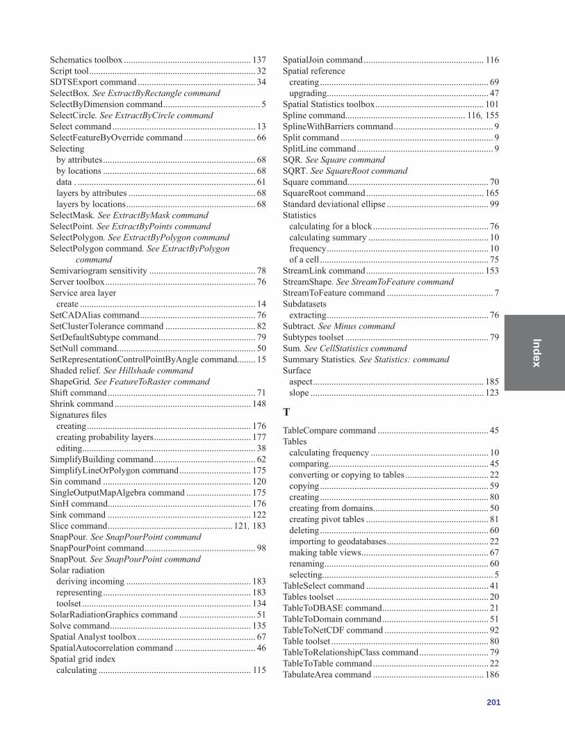
Index
201
Schematics toolbox ....................................................... 137Script tool ........................................................................ 32SDTSExport command ................................................... 34SelectBox. See ExtractByRectangle commandSelectByDimension command .......................................... 5SelectCircle. See ExtractByCircle commandSelect command .............................................................. 13SelectFeatureByOverride command ............................... 66Selecting
by attributes .................................................................. 68by locations .................................................................. 68data . ............................................................................. 61layers by attributes ....................................................... 68layers by locations ........................................................ 68
SelectMask. See ExtractByMask commandSelectPoint. See ExtractByPoints commandSelectPolygon. See ExtractByPolygon commandSelectPolygon command. See ExtractByPolygon
commandSemivariogram sensitivity .............................................. 78Server toolbox ................................................................. 76Service area layer
create ............................................................................ 14SetCADAlias command .................................................. 76SetClusterTolerance command ....................................... 82SetDefaultSubtype command .......................................... 79SetNull command ............................................................ 50SetRepresentationControlPointByAngle command ........ 15Shaded relief. See Hillshade commandShapeGrid. See FeatureToRaster commandShift command ................................................................ 71Shrink command ........................................................... 148Signatures files
creating ....................................................................... 176creating probability layers .......................................... 177editing ........................................................................... 38
SimplifyBuilding command ............................................ 62SimplifyLineOrPolygon command ............................... 175Sin command ................................................................ 120SingleOutputMapAlgebra command ............................ 175SinH command .............................................................. 176Sink command .............................................................. 122Slice command ...................................................... 121, 183SnapPour. See SnapPourPoint commandSnapPourPoint command ................................................ 98SnapPout. See SnapPourPoint commandSolar radiation
deriving incoming ...................................................... 183representing ................................................................ 183toolset ......................................................................... 134
SolarRadiationGraphics command ................................. 51Solve command ............................................................. 135Spatial Analyst toolbox ................................................... 67SpatialAutocorrelation command ................................... 46Spatial grid index
calculating .................................................................. 115
SpatialJoin command .................................................... 116Spatial reference
creating ......................................................................... 69upgrading...................................................................... 47
Spatial Statistics toolbox ............................................... 101Spline command .................................................... 116, 155SplineWithBarriers command ........................................... 9Split command .................................................................. 9SplitLine command ........................................................... 9SQR. See Square commandSQRT. See SquareRoot commandSquare command ............................................................. 70SquareRoot command ................................................... 165Standard deviational ellipse ............................................ 99Statistics
calculating for a block .................................................. 76calculating summary .................................................... 10frequency ...................................................................... 10of a cell ......................................................................... 75
StreamLink command ................................................... 153StreamShape. See StreamToFeature commandStreamToFeature command .............................................. 7Subdatasets
extracting ...................................................................... 76Subtract. See Minus commandSubtypes toolset .............................................................. 79Sum. See CellStatistics commandSummary Statistics. See Statistics: commandSurface
aspect .......................................................................... 185slope ........................................................................... 123
tTableCompare command ................................................ 45Tables
calculating frequency ................................................... 10comparing ..................................................................... 45converting or copying to tables .................................... 22copying ......................................................................... 59creating ......................................................................... 80creating from domains.................................................. 50creating pivot tables ..................................................... 81deleting ......................................................................... 60importing to geodatabases ............................................ 22making table views ....................................................... 67renaming ....................................................................... 60selecting.......................................................................... 5
TableSelect command ..................................................... 41Tables toolset .................................................................. 20TableToDBASE command .............................................. 21TableToDomain command .............................................. 51TableToNetCDF command ............................................. 92Table toolset .................................................................... 80TableToRelationshipClass command .............................. 79TableToTable command .................................................. 22TabulateArea command ................................................ 186

Inde
x
202 ArcGIS 9: Geoprocessing Commands Quick Reference Guide
Tan command ................................................................ 176TanH command ............................................................. 176Temporary layers
making. See Layers and Table Views toolsetTerrains
adding feature class .................................................... 123adding pyramid........................................................... 124building ...................................................................... 124creating ....................................................................... 124points .................................................................. 124, 125reference scale ............................................................ 124remove pyramid ......................................................... 125
Terrain toolset ............................................................... 123TerrainToRaster command ............................................ 111TerrainToTin command ................................................. 111Test command ............................................................... 172Thiessen
polygons ....................................................................... 32Thiessen command .......................................................... 33Thin command .............................................................. 149Times command .................................................... 120, 165TINArc. See FeatureClassToCoverage commandTinAspect command ..................................................... 127TinContour command ................................................... 127TIN Creation toolset ..................................................... 125TinDifference command ............................................... 127TinDomain command ................................................... 111TinEdge command ........................................................ 112TINHull. See TINDomain commandTINLattice. See TINRaster commandTinLine command ......................................................... 112TINLines. See TINEdge commandTinNode command ........................................................ 112TinPolygonTag command ............................................. 112TinPolygonVolume command ....................................... 127TinRaster command ...................................................... 113TINs
calculating aspect ....................................................... 127calculating contours ................................................... 127calculating slope ......................................................... 127converting to raster datasets ....................................... 113creating ....................................................................... 125editing ......................................................................... 126extracting edges .......................................................... 112extracting interpolation zones .................................... 111extracting nodes ......................................................... 112extracting polygon tag information ............................ 112extracting triangle polygons ....................................... 113
TinSlope command ....................................................... 127TINSpot. See SurfaceSpot commandTIN Surface toolset ....................................................... 126TinTriangle command ..................................................... 20To CAD toolset ............................................................... 19To Coverage toolset ........................................................ 20To dBASE toolset ........................................................... 42To Geodatabase toolset ................................................... 42
To KML toolset ....................................................... 22, 113Tolerance
command ...................................................................... 11setting cluster tolerances .............................................. 82
Tolerances toolset .............................................................. 1Tool
licensing .....................................................................A-1Toolbox
3D Analyst .................................................................. 109Analysis ........................................................................ 87Cartography .................................................................... 1Conversion ................................................................... 89Coverage ...................................................................... 91Data Interoperability .................................................. 129Data Management .......................................................... 1described ...................................................................... 93Geocoding ...................................................................... 1Geostatistical Analyst ................................................. 131Linear Referencing ....................................................... 97Mobile .......................................................................... 34Multidimension ............................................................ 27Network Analyst......................................................... 133Schematics.................................................................. 137Server ........................................................................... 35Spatial Analyst ........................................................... 139Spatial Statistics ........................................................... 31Tracking Analyst ........................................................ 189
Toolscustom .......................................................................... 34model ............................................................................ 97script ............................................................................. 46system ........................................................................... 93
ToolsetAggregate ..................................................................... 48Analysis ........................................................................ 49Analyzing Patterns ....................................................... 67Bitwise........................................................................ 165Caching ........................................................................ 51Composite Features ...................................................... 31Conditional ................................................................. 139Conversion ................................................................... 17Database ....................................................................... 56Data Comparison .......................................................... 52Data Management ........................................................ 36Density ....................................................................... 140described ...................................................................... 11Disconnected Editing ................................................... 39Distance ...................................................................... 141Distributed Geodatabase .............................................. 39Domains ....................................................................... 39Extract .......................................................................... 11Extraction ................................................................... 145Feature .......................................................................... 69Feature Class ................................................................ 18Features ........................................................................ 53Fields ............................................................................ 57

Index
203
From Coverage ............................................................... 8From Feature Class .................................................... 111From File .................................................................... 111From Raster ................................................................ 113From Terrain ................................................................. 40From TIN ..................................................................... 98Functional Surface ..................................................... 114General ......................................................................... 59Generalization ................................................ 149, 61, 70Graphic Quality .......................................................... 151Groundwater ................................................................. 67Hydrology .................................................................. 154Indexes ......................................................................... 72Interpolation ................................................................. 12Items ............................................................................. 72Joins ........................................................................... 157Layers and Table Views ............................................... 66licensing .....................................................................A-1Local ........................................................................... 159Logical.......................................................................... 13Map Algebra ............................................................... 160Mapping Clusters ....................................................... 160Masking ........................................................................ 41Math ............................................................................. 75Measuring Geographic Distributions ........................... 99Metadata ..................................................................... 179Multivariate .................................................................. 18Neighborhood ............................................................... 19Network Dataset ......................................................... 135Overlay ......................................................................... 75Projections .................................................................. 134Projections and Transformations .................................. 68Proximity ..........................................................................Raster............................................................................ 70Raster Catalog .............................................................. 76Raster Creation ............................................................. 42Raster Dataset............................................................... 73Raster Interpolation ...................................................... 22Raster Math .................................................................. 24Raster Processing ......................................................... 75Raster Properties .......................................................... 77Raster Reclass ............................................................ 120Raster Surface ............................................................ 121Reclass........................................................................ 182Relationship Classes..................................................... 78Representation Management ...................................... 183Solar Radiation ............................................................. 42Subtypes ....................................................................... 79Surface.......................................................................... 77Symbolization Refinement ........................................... 78Table ............................................................................. 80Tables ......................................................................... 123Terrain ........................................................................ 124TIN Creation .............................................................. 125TIN Surface ................................................................ 126To CAD ........................................................................ 19
To Coverage ................................................................. 20To dBASE .................................................................... 79To Geodatabase ............................................................ 24To KML ........................................................................ 22Tolerances .................................................................... 67Topology .................................................................... 135To Raster ...................................................................... 23To Shapefile .................................................................. 25Trigonometric ............................................................. 173Turn Feature Class ....................................................... 57Versions ........................................................................ 83
Topologyremoving rules .............................................................. 82toolset ......................................................................... 116
To Raster toolset ............................................................. 23Transform command ..................................................... 117Transforming
route events ................................................................ 172TransformRouteEvents command ................................. 135TransposeTimeFields command ..................................... 58Trend command ............................................................ 118Trigonometric toolset .................................................... 173
UUncompressFileGeodatabaseData command .................. 58Uncompressing
dataset ........................................................................... 58Underpasses
creating ........................................................................... 7UnregisterAsVersioned command .................................. 84Unregistering
as versioned .................................................................. 84UpdateAnnotation command .......................................... 52UpdateByAlternateIDFields command ......................... 136UpdateByGeometry command ...................................... 136Update command ............................................................ 13UpdateDiagram command ............................................ 137UpdateDiagrams command ........................................... 137UpdateGlobeServerCache command .............................. 95UpdateMapServerCache command ................................ 95UpdateOverride command ..................................................Updating
IDs 46UpgradeSpatialReference command ............................... 47
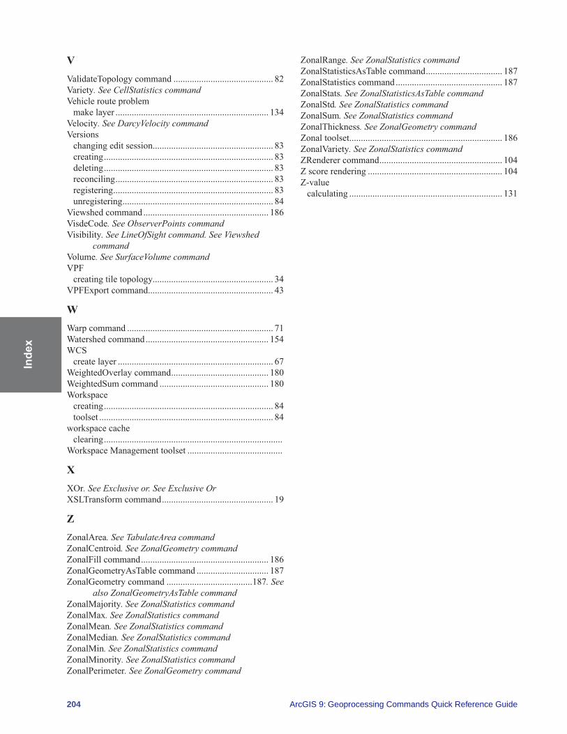
Inde
x
204 ArcGIS 9: Geoprocessing Commands Quick Reference Guide
vValidateTopology command ........................................... 82Variety. See CellStatistics commandVehicle route problem
make layer .................................................................. 134Velocity. See DarcyVelocity commandVersions
changing edit session.................................................... 83creating ......................................................................... 83deleting ......................................................................... 83reconciling .................................................................... 83registering ..................................................................... 83unregistering ................................................................. 84
Viewshed command ...................................................... 186VisdeCode. See ObserverPoints commandVisibility. See LineOfSight command. See Viewshed
commandVolume. See SurfaceVolume commandVPF
creating tile topology.................................................... 34VPFExport command ...................................................... 43
WWarp command ............................................................... 71Watershed command ..................................................... 154WCS
create layer ................................................................... 67WeightedOverlay command .......................................... 180WeightedSum command ............................................... 180Workspace
creating ......................................................................... 84toolset ........................................................................... 84
workspace cacheclearing .............................................................................
Workspace Management toolset .........................................
XXOr. See Exclusive or. See Exclusive OrXSLTransform command ................................................ 19
ZZonalArea. See TabulateArea commandZonalCentroid. See ZonalGeometry commandZonalFill command ....................................................... 186ZonalGeometryAsTable command ............................... 187ZonalGeometry command .....................................187. See
also ZonalGeometryAsTable commandZonalMajority. See ZonalStatistics commandZonalMax. See ZonalStatistics commandZonalMean. See ZonalStatistics commandZonalMedian. See ZonalStatistics commandZonalMin. See ZonalStatistics commandZonalMinority. See ZonalStatistics commandZonalPerimeter. See ZonalGeometry command
ZonalRange. See ZonalStatistics commandZonalStatisticsAsTable command ................................. 187ZonalStatistics command .............................................. 187ZonalStats. See ZonalStatisticsAsTable commandZonalStd. See ZonalStatistics commandZonalSum. See ZonalStatistics commandZonalThickness. See ZonalGeometry commandZonal toolset .................................................................. 186ZonalVariety. See ZonalStatistics commandZRenderer command ..................................................... 104Z score rendering .......................................................... 104Z-value
calculating .................................................................. 131

Appendix A
A-1
Appendix A: Tool licensing Thecoretoolboxescontainamixtureoftoolsavailablewithspecificlicenselevels.Theseareshown in the tables below. The Coverage toolbox is only available with the ArcInfo license. All tools provided with extensions are available at any license level.
Analysis toolbox
Toolset/Tool ArcView ArcEditor ArcInfoExtract toolset
Clip
Select
Split
Table Select
Overlay toolsetErase
Identity
Intersect
SpatialJoin
Symmetrical Difference
Union
Update
Proximity toolsetBuffer
CreateThiessenPolygons
Generate Near TableMultipleRingBuffer
Near
PointDistance
Statistics toolsetFrequency
Summary Statistics

App
endi
x A
A-2
Cartography toolbox
Toolset/Tool ArcView ArcEditor ArcInfoGraphic Quality toolset
DetectGraphicConflict
Masking Tools toolsetCul-De-Sac Masks
FeatureOutlineMasks
Intersecting Layers Masks
Representation Management toolsetAdd Representation
Calculate Representation Rule
Drop Representation
RemoveOverride
SelectFeatureByOverride
Set Layer Representation
UpdateOverride
Symbolization Refinement toolsetAlignMarkerToStrokeOrFill
Calculate Geodesic Angle
Calculate Line Caps
CalculatePolygonMainAngle
CreateOverpass
Create Underpass
Disperse Markers
SetRepresentationControlPointByIntersect
SetRepresentationControlPointByAngle
Conversion toolbox
Toolset/Tool ArcView ArcEditor ArcInfoFrom Raster toolset
Raster To ASCII
RasterToFloat
RasterToPoint
RasterToPolygon
RasterToPolyline
From WFSWFSToFeatureClass

Appendix A
A-3
Metadata toolset (Conversion toolbox cont.) ArcView ArcEditor ArcInfoESRI Metadata Translator
Metadata Importer
MetadataPublisher
USGSMPMetadataTranslator
XSLTTranslator
To CAD toolsetAddCADFields
CreateCADXData
Export To CAD
Set CAD Alias
To Coverage toolsetFeatureClassToCoverage
To dBASE toolsetTableTodBASE(multiple)
To Geodatabase toolsetFeatureClassToFeatureClass
FeatureClassToGeodatabase(multiple)
Import CAD Annotation
Import Coverage Annotation
ImportFromCAD
RasterToGeodatabase(multiple)
TableToGeodatabase(multiple)
Table To Table
To KMLLayer To KML
Map To KML
To Raster toolsetASCII To Raster
DEM To Raster
FeatureToRaster
FloatToRaster
PointToRaster
PolygonToRaster
PolylineToRaster
RasterToOtherFormat(multiple)
To Shapefile toolsetFeatureClassToShapefile(multiple)
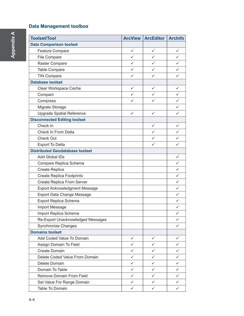
App
endi
x A
A-4
Data Management toolbox
Toolset/Tool ArcView ArcEditor ArcInfoData Comparison toolset
FeatureCompare
FileCompare
Raster Compare
Table Compare
TIN Compare
Database toolsetClearWorkspaceCache
Compact
Compress
Migrate Storage
Upgrade Spatial Reference
Disconnected Editing toolsetCheck In
CheckInFromDelta
CheckOut
Export To Delta
Distributed Geodatabase toolsetAdd Global IDs
Compare Replica Schema
Create Replica
CreateReplicaFootprints
CreateReplicaFromServer
Export Acknowledgment Message
Export Data Change Message
Export Replica Schema
Import Message
Import Replica Schema
Re-Export Unacknowledged Messages
SynchronizeChanges
Domains toolsetAddCodedValueToDomain
AssignDomainToField
Create Domain
DeleteCodedValueFromDomain
Delete Domain
Domain To Table
RemoveDomainFromField
SetValueForRangeDomain
Table To Domain

Appendix A
A-5
Feature Class toolset (Data Management cont.) ArcView ArcEditor ArcInfoAppendAnnotationFeatureClasses
Calculate Default Cluster Tolerance
Calculate Default Spatial Grid Index
CreateFeatureClass
CreateFishnet
CreateRandomPoints
Integrate
UpdateAnnotationFeatureClass
Features toolsetAddXYCoordinates
Adjust3DZ
Check Geometry
CopyFeatures
DeleteFeatures
FeatureEnvelopeToPolygon
FeatureToLine
FeatureToPoint
FeatureToPolygon
FeatureVerticesToPoints
Multipart To Singlepart
PolygonToLine
Repair Geometry
SplitLineAtVertices
Fields toolsetAddField
AssignDefaultToField
Calculate End Date
CalculateField
DeleteField
TransposeTimeFields
File Geodatabase toolsetCompressFileGeodatabaseData
UncompressFileGeodatabaseData
General toolsetAppend
CalculateValue
Copy
Delete
Merge
MergeBranch
Rename
Select Data

App
endi
x A
A-6
Generalization toolset (Data Managment cont.) ArcView ArcEditor ArcInfoAggregatePolygons
Collapse Dual Lines To Centerline
Dissolve
Eliminate
SimplifyBuilding
Simplify Line
SimplifyPolygon
Smooth Line
SmoothPolygon
Indexes toolsetAdd Attribute Index
Add Spatial Index
Remove Attribute Index
Remove Spatial Index
Joins toolsetAddJoin
JoinField
RemoveJoin
Layers and Table Views toolsetApplySymbologyFromLayer
MakeFeatureLayer
Make Image Server Layer
MakeQueryTable
Make Raster Catalog Layer
Make Raster Layer
MakeTableView
MakeWCSLayer
MakeXYEventLayer
SaveToLayerFile
SelectLayerByAttribute
SelectLayerByLocation
Projections and Transformations toolsetCreate Custom Geographic Transformation
DefineProjection
Feature toolsetBatchProject
Create Spatial Reference
Project
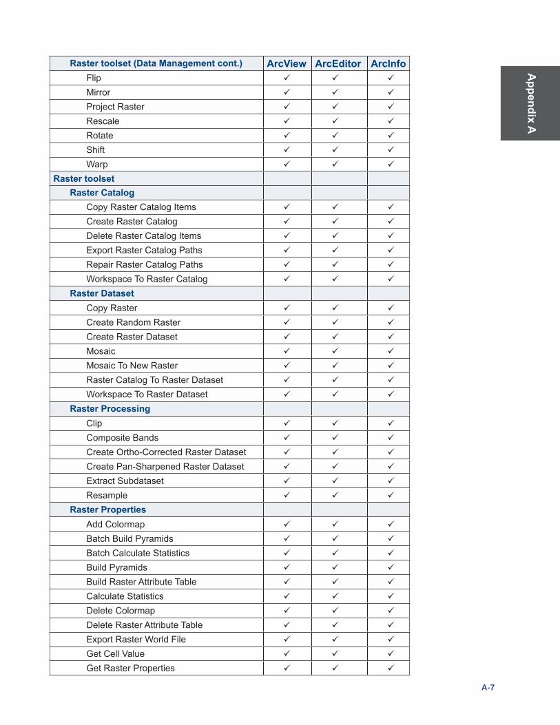
Appendix A
A-7
Raster toolset (Data Management cont.) ArcView ArcEditor ArcInfoFlip
Mirror
ProjectRaster
Rescale
Rotate
Shift
Warp
Raster toolsetRaster Catalog
Copy Raster Catalog Items
Create Raster Catalog
Delete Raster Catalog Items
ExportRasterCatalogPaths
RepairRasterCatalogPaths
WorkspaceToRasterCatalog
Raster DatasetCopy Raster
Create Random Raster
Create Raster Dataset
Mosaic
Mosaic To New Raster
Raster Catalog To Raster Dataset
WorkspaceToRasterDataset
Raster ProcessingClip
CompositeBands
CreateOrtho-CorrectedRasterDataset
CreatePan-SharpenedRasterDataset
Extract Subdataset
Resample
Raster PropertiesAdd Colormap
BatchBuildPyramids
BatchCalculateStatistics
BuildPyramids
BuildRasterAttributeTable
Calculate Statistics
Delete Colormap
Delete Raster Attribute Table
ExportRasterWorldFile
GetCellValue
GetRasterProperties

App
endi
x A
A-8
Relationship Classes toolset (Data Mgmt.) ArcView ArcEditor ArcInfoCreate Relationship Class
Table To Relationship Class
Subtypes toolsetAdd Subtype
Remove Subtype
Set Default Subtype
SetSubtypeField
Table toolsetAnalyze
ChangePrivileges
Copy Rows
Create Table
Delete Rows
Get Count
PivotTable
Topology toolsetAddFeatureClassToTopology
Add Rule To Topology
Create Topology
RemoveFeatureClassFromTopology
RemoveRuleFromTopology
Set Cluster Tolerance
ValidateTopology
Versions toolsetAlterVersion
CreateVersion
DeleteVersion
PostVersion
ReconcileVersion
RegisterAsVersioned
UnregisterAsVersioned
Workspace toolsetCreateArcInfoWorkspace
CreateFeatureDataset
CreateFileGeodatabase
CreateFolder
CreatePersonalGeodatabase
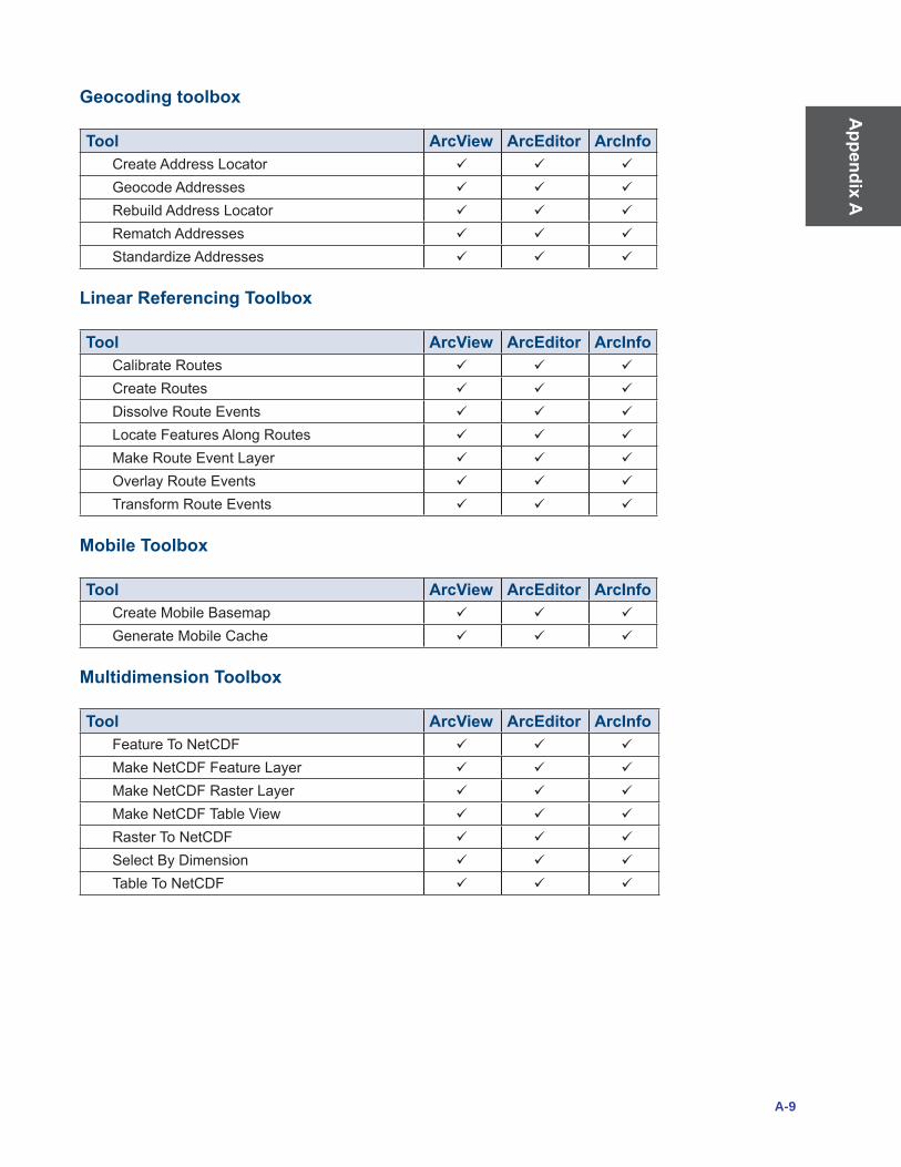
Appendix A
A-9
Geocoding toolbox
Tool ArcView ArcEditor ArcInfoCreate Address Locator
Geocode Addresses
Rebuild Address Locator
Rematch Addresses
StandardizeAddresses
Linear Referencing Toolbox
Tool ArcView ArcEditor ArcInfoCalibrate Routes
Create Routes
Dissolve Route Events
LocateFeaturesAlongRoutes
Make Route Event Layer
OverlayRouteEvents
Transform Route Events
Mobile Toolbox
Tool ArcView ArcEditor ArcInfoCreateMobileBasemap
Generate Mobile Cache
Multidimension Toolbox
Tool ArcView ArcEditor ArcInfoFeatureToNetCDF
MakeNetCDFFeatureLayer
MakeNetCDFRasterLayer
MakeNetCDFTableView
RasterToNetCDF
SelectByDimension
TableToNetCDF

App
endi
x A
A-10
Server Toolbox
Tool ArcView ArcEditor ArcInfoCaching toolset
Create Map Server Cache
Delete Globe Server Cache
Delete Map Server Cache
Generate Map Server Cache Tiling Scheme
Manage Globe Server Cache Tiles
Manage Map Server Cache Scales
Manage Map Server Cache Tiles Requires 3D Analyst extension
Spatial Statistics toolbox
Toolset/Tool ArcView ArcEditor ArcInfoAnalyzing Patterns toolset
Average Nearest Neighbor
High/LowClustering(Getis-OrdGeneralG)
Multi-Distance Spatial Cluster Analysis (Ripley’sKFunction)
SpatialAutocorrelation(MoransI)
Mapping Clusters toolsetClusterAndOutlierAnalysis(AnselinLocalMoransI)
HotSpotAnalysis(Getis-OrdGi*)
Measuring Geographic Distributions toolsetCentralFeature
DirectionalDistribution(StandardDeviationalEllipse)
Linear Directional Mean
Mean Center
Standard Distance
Modeling Spatial RelationshipsGenerateNetworkSpatialWeights
GenerateSpatialWeightsMatrix
GeographicallyWeightedRegression
OrdinaryLeastSquares Requires the Network Analyst extension Requires the Spatial Analyst extension
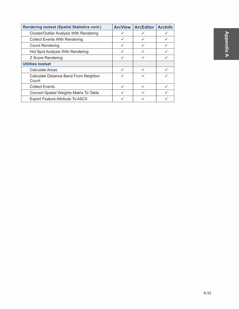
Appendix A
A-11
Rendering toolset (Spatial Statistics cont.) ArcView ArcEditor ArcInfoCluster/OutlierAnalysisWithRendering
CollectEventsWithRendering
Count Rendering
HotSpotAnalysisWithRendering
ZScoreRendering
Utilities toolsetCalculate Areas
CalculateDistanceBandFromNeighborCount
Collect Events
ConvertSpatialWeightsMatrixToTable
ExportFeatureAttributeToASCII

App
endi
x A
A-12
Top Related