


Languages
Pages
Legal


Digital Valve Control Module
(VCM)
This manual contains important information for the safe and effective operation of the Swagelok® digital valve control module. Users should read and understand its contents before operating the valve control module.
User’s Manual
www.swagelok.com

2 Valve Control Module User’s Manual
SafetySignal Words Used in this ManualNOTICE Statements that indicate a hazardous situation which, if not avoided, could result in damage to the
equipment or other property.
ContentsSafety 2
Introduction 3
Product Information 4
Specifications 5
Control Drawing 6
Installation 7
Mounting . . . . . . . . . . . . . . . . . . . . . . . . . . . 7
Grounding . . . . . . . . . . . . . . . . . . . . . . . . . . 7
Air Supply Quality . . . . . . . . . . . . . . . . . . . . . . 7
Power Supply. . . . . . . . . . . . . . . . . . . . . . . . . 8
DeviceNet™ Network Cable . . . . . . . . . . . . . . . . . 8
Tubing Connections . . . . . . . . . . . . . . . . . . . . . 9
Proximity Sensor . . . . . . . . . . . . . . . . . . . . . . 10
Terminal Strip (SS-VCM-D-6-2). . . . . . . . . . . . . 10
Setup 12
Electronic Data Sheet (EDS) . . . . . . . . . . . . . . . . 12
General Tab . . . . . . . . . . . . . . . . . . . . . . . 13
Parameter Tab . . . . . . . . . . . . . . . . . . . . . 13
Operation 15
Commanding the VCM . . . . . . . . . . . . . . . . . . 16
Response from the VCM . . . . . . . . . . . . . . . . . . 16
Maintenance 17
Troubleshooting 18
Glossary 19
Valve Control Module User’s Manual 3
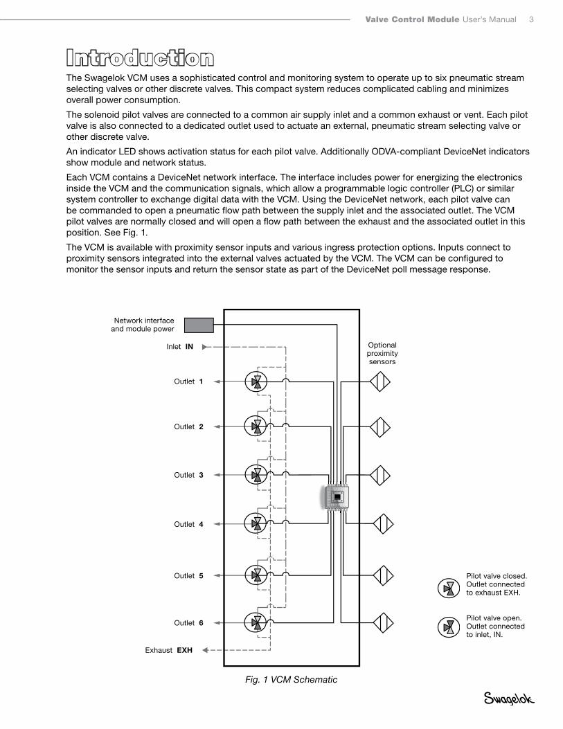
IntroductionThe Swagelok VCM uses a sophisticated control and monitoring system to operate up to six pneumatic stream selecting valves or other discrete valves. This compact system reduces complicated cabling and minimizes overall power consumption.
The solenoid pilot valves are connected to a common air supply inlet and a common exhaust or vent. Each pilot valve is also connected to a dedicated outlet used to actuate an external, pneumatic stream selecting valve or other discrete valve.
An indicator LED shows activation status for each pilot valve. Additionally ODVA-compliant DeviceNet indicators show module and network status.
Each VCM contains a DeviceNet network interface. The interface includes power for energizing the electronics inside the VCM and the communication signals, which allow a programmable logic controller (PLC) or similar system controller to exchange digital data with the VCM. Using the DeviceNet network, each pilot valve can be commanded to open a pneumatic flow path between the supply inlet and the associated outlet. The VCM pilot valves are normally closed and will open a flow path between the exhaust and the associated outlet in this position. See Fig. 1.
The VCM is available with proximity sensor inputs and various ingress protection options. Inputs connect to proximity sensors integrated into the external valves actuated by the VCM. The VCM can be configured to monitor the sensor inputs and return the sensor state as part of the DeviceNet poll message response.
Fig. 1 VCM Schematic
Optional proximity sensors
Pilot valve open.Outlet connected to inlet, IN.
Inlet IN
Outlet 1
Outlet 2
Outlet 3
Outlet 4
Outlet 5
Outlet 6
Exhaust EXH
Network interface and module power
Pilot valve closed.Outlet connected to exhaust EXH.

4 Valve Control Module User’s Manual
Product Information
Fig. 2 MS-VCMD-6-2
Mounting holes
Grounding lug
Interface cover
Valve #1 LED
Network LED
Module LED
M12 Network Connector Plug
Exhaust
Cable gland
Mounting holes
Inlet
Outlets

Valve Control Module User’s Manual 5
SpecificationsPower
Voltage 24 V (dc), nominal
Current < 310 mA (dc) at 24 V (dc)
Wattage < 7.5 W at 24 V (dc)
Temperature
Operating (Ambient) Minimum 23°F (–5°C)
Maximum 122°F (50°C)
Media Minimum 23°F (–5°C)
Maximum 122°F (50°C)
Storage Minimum –4°F (–20°C)
Maximum 140°F (60°C)
Weight 3.5 lb (1.6 kg)
Ingress Protection IP64
Inlet Air
Pressure 40 to 116 psig (1.6 to 7.9 bar)
Air Quality Filtered compressed air, lubricated or
unlubricated, grade of filtration 40 μm
Entity ParametersSee control drawing VCM-DN-0011-SCHEDULE on page 6.
Supported Communication Baud Rates
Auto-baud function, allowing the device to detect the speed of network traffic. It is compatible with 125, 250, and 500 kbaud rates.
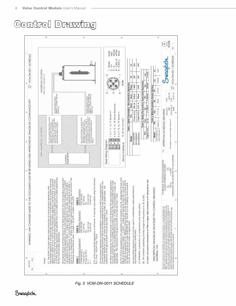
Note: Before installing the VCM in a hazardous location, review the control drawing on page 6. This will help ensure all electrical connections to and from the VCM comply with safety requirements. For an electronic copy of this document, see Swagelok.com
6 Valve Control Module User’s Manual
Control Drawing
Fig. 3 VCM-DN-0011 SCHEDULE
4532 1
1, 4
, 7, 1
1, 1
4, 1
7: S
enso
r V+
2, 5
, 8, 1
2, 1
5, 1
8: S
enso
r Res
pons
e
3, 6
, 9, 1
3, 1
6, 1
9: S
enso
r V-
10, 2
0: N
o C
onne
ct
Not
es:
(1)
The
Entit
y C
once
pt a
llow
s int
erco
nnec
tion
of n
onin
cend
ive
appa
ratu
s with
as
soci
ated
app
arat
us n
ot sp
ecifi
cally
exa
min
ed in
com
bina
tion
as a
syst
em w
hen
the
appr
oved
val
ues o
f Voc
and
Isc
of th
e as
soci
ated
app
arat
us a
re le
ss th
an o
r equ
al to
V
max
and
Imax
of t
he n
onin
cend
ive
appa
ratu
s and
the
appr
oved
val
ues o
f Ca
and
La
of t
he a
ssoc
iate
d a
ppar
atus
are
gre
ater
than
Ci+
Cca
ble
and
Li+
Lcab
le re
spec
tivel
y fo
r the
non
ince
ndiv
e ap
para
tus.
(2) C
apac
itanc
e an
d in
duc
tanc
e of
the
field
wiri
ng fr
om th
e no
ninc
end
ive
equi
pmen
t to
the
asso
ciat
ed a
ppar
atus
shal
l be
calc
ulat
ed a
nd m
ust b
e in
clud
ed in
the
syst
em
calc
ulat
ions
as s
how
n in
Tab
le 1
. C
able
cap
acita
nce,
Cca
ble,
plu
s non
ince
ndiv
e eq
uipm
ent c
apac
itanc
e, C
i, m
ust b
e le
ss th
an th
e m
arke
d c
apac
itanc
e (L
cabl
e, L
i an
d L
a or
Lo,
resp
ectiv
ely)
. W
here
the
cabl
e ca
paci
tanc
e pe
r foo
t are
not
kno
wn,
the
follo
win
g va
lues
shal
l be
used
: C
cabl
e =
60 p
F/ft.
, Lca
ble
= 0.
2 µ H
/ft.
TABL
E 1:
TA
BLE
2:
TA
BLE
3:N
onin
cend
ive
Equi
pmen
t
A
ssoc
iate
d A
ppar
atus
S
enso
r Int
erfa
ceV
max
(or U
i) ≥
V
oc (o
r Uo)
V
oc (o
r Uo)
I max
(or I
i) ≥
Isc
(or l
o)
Isc (o
r lo)
P m
ax (o
r Pi) ≥
P
o
P
oC
i ≤
C
a (o
r Co)
Ca
(or C
o)Li
≤
La
(or L
o)
L
a (o
r Lo)
If Po
of t
he a
ssoc
iate
d a
ppar
atus
is n
ot k
now
n, it
may
be
calc
ulat
ed u
sing
the
form
ula:
Po
= (V
oc *
Isc)
/4 =
(Uo
* Io
)/4.
(3) A
ssoc
iate
d a
ppar
atus
mus
t be
inst
alle
d in
acc
ord
ance
with
its m
anuf
actu
rer's
co
ntro
l dra
win
g an
d A
rticl
e 50
4 of
the
Nat
iona
l Ele
ctric
al C
ode
(AN
SI/N
FPA
70)
, the
C
anad
ian
Elec
trica
l Cod
e, o
r oth
er lo
cal in
stal
latio
n co
des
, as a
pplic
able
. Th
e re
sista
nce
of th
e gr
ound
pat
h m
ust b
e le
ss th
an 1
ohm
.
(4) W
hen
requ
ired
by
the
man
ufac
ture
r's c
ontro
l dra
win
g, th
e as
soci
ated
app
arat
us
mus
t be
conn
ecte
d to
a su
itabl
e gr
ound
ele
ctro
de
per t
he N
atio
nal E
lect
rical
Cod
e (A
NSI
/NFP
A 7
0), t
he C
anad
ian
Elec
trica
l Cod
e, o
r oth
er lo
cal in
stal
latio
n co
des
, as
appl
icab
le.
The
resis
tanc
e of
the
grou
nd p
ath
mus
t be
less
than
1 o
hm.
(5) T
he V
CM
is p
ower
ed b
y tw
o se
para
te n
onin
cend
ive
circ
uits
, des
igna
ted
Pow
er a
nd
Sign
al a
s ind
icat
ed in
Tab
les 1
, 2 a
nd 3
. C
able
and
wiri
ng fo
r the
se tw
o ci
rcui
ts m
ust
mai
ntai
n th
e se
para
tions
for d
iffer
ent n
onin
cend
ive
circ
uits
requ
ired
by
Arti
cle
504
of
the
Nat
iona
l Ele
ctric
al C
ode
(AN
SI/N
FPA
70)
, ISA
RP1
2.6
for i
nsta
lling
noni
ncen
div
e ci
rcui
ts, o
r oth
er lo
cal c
odes
, as a
pplic
able
.
(6) A
ssoc
iate
d a
ppar
atus
mus
t not
be
used
in c
ombi
natio
n un
less
per
mitt
ed b
y as
soci
ated
app
arat
us c
ertif
icat
ion.
(7) W
ARN
ING
: Su
bstit
utio
n of
com
pone
nts m
ay im
pair
safe
ty.
(8)
The
ambi
ent o
pera
ting
(Tam
b) ra
nge
for t
his p
rod
uct i
s -5C
to 5
0C.
(9) E
ach
unit
mus
t be
conn
ecte
d to
an
IP64
or h
ighe
r rat
ed c
onne
ctor
or I
P ra
ting
will
be
void
.
HAZA
RDO
US L
OC
ATIO
NC
lass
I, D
iv. 2
, Gro
ups C
, D
Any
ass
ocia
ted
app
arat
us p
ower
su
pply
with
Ent
ity C
once
pt
Para
met
ers (
1) a
ppro
pria
te fo
r co
nnec
tion
to a
n no
ninc
end
ive
dev
ice
with
Ent
ity c
once
pt
para
met
ers l
isted
in T
able
1.
Any
non
ince
ndiv
e or
ass
ocia
ted
ap
para
tus c
omm
unic
atio
n co
ntro
ller w
ith E
ntity
Con
cept
pa
ram
eter
s (1)
(Vm
ax, I
max
, Ci,
Li) a
ppro
pria
te fo
r con
nect
ions
to
noni
ncen
div
e d
evic
es w
ith E
ntity
C
once
pt p
aram
eter
s list
ed in
Ta
ble
1.
NO
N-H
AZA
RDO
US L
OC
ATIO
N
CO
NTR
OL
EQUI
PMEN
T
NO
NIN
CEN
DIV
E FI
ELD
WIR
ING
- PO
WER
CIR
CUI
T(P
INS
2,3)
NO
NIN
CEN
DIV
E FI
ELD
/A
SSO
CIA
TED
APP
ARA
TUS
WIR
ING
- SI
GN
AL
CIR
CUI
T(P
INS
4,5)
Fiel
d W
iring
Dia
gram
1 - D
rain
bar
e2
- V+
r
ed3
- V-
b
lack
4 - C
AN
_H
whi
te5
- CA
N_L
b
lue
WA
RNIN
G: A
NY
CHA
NG
ES M
AD
E TO
THI
S D
OC
UMEN
T M
UST
BE R
EVIE
WED
AN
D A
PPRO
VED
BY
SWA
GEL
OK
CO
MPL
IAN
CE
DPT
MA
TERI
AL:
NA
DES
CRI
PTIO
N: S
WA
GEL
OK
DEV
ICEN
ET P
TX C
ON
TRO
L D
RAW
ING
Mal
eSe
nsor
Inte
rface
DW
G.
NO
.VC
M-D
N-0
011-
SCHE
DUL
E
TITLE
DRA
WN
BY
CHE
CK/
APR
BY
JEK
DW
G.
NO
.VC
M-D
N-0
011-
SCHE
DUL
E
THIS
PRI
NT
IS T
HE E
XCLU
SIV
E PR
OPE
RTY
OF
SWA
GEL
OK
CO
MPA
NY.
IT
MUS
T BE
RET
URN
ED O
N
REQ
UEST
ALO
NG
WITH
AN
Y D
OC
UMEN
TS C
ON
TAIN
ING
INFO
RMA
TION
OBT
AIN
ED F
ROM
THI
S PR
INT.
NEI
THER
THI
S PR
INT
NO
R A
NY
PART
OF
IT N
OR
AN
Y IN
FORM
ATIO
N C
ON
CER
NIN
G IT
MA
Y BE
CO
PIED
, D
ISC
LOSE
D T
O O
THER
S O
R US
ED F
OR
AN
Y PU
RPO
SE E
XCEP
T IN
FUR
THER
AN
CE
OF
YOUR
BUS
INES
S W
ITH S
WA
GEL
OK.
THE
PA
RTS
REFE
RRED
TO
ON
THI
S PR
INT
MA
Y BE
THE
SU
BJEC
T O
F PA
TEN
TS A
ND
/OR
PEN
DIN
G A
PPLIC
ATIO
NS
AN
D M
AY
NO
T BE
MA
NUF
AC
TURE
D
WITH
OUT
PER
MIS
SIO
N F
ROM
SW
AG
ELO
K C
OM
PAN
Y.
SCA
LEN
ON
ERE
V.-
SHEE
T 1
of 1
REVI
SIO
NS
TOLE
RAN
CE
ON
EN
GLIS
H D
IMEN
SIO
NS
UNLE
SS O
THER
WIS
E SP
ECIF
IED
76
54
32
1
D C B A
8 87
65
43
21
ABCD
APP
ROV
AL/
SCHE
DUL
E D
RAW
ING
.X
X
.0
31
.XXX
.015
A
NG
LES
1
DEG
REE
DC
N R
EV.
Jul-9
-12
DA
TE
DA
TEM
JRJu
l-9-1
2--
DIM
ENSI
ON
S A
RE IN
CHE
S N
EXT
TO [M
ILLIM
ETER
S].
© S
wag
elok
Com
pany
All R
ight
s Res
erve
d

Valve Control Module User’s Manual 7
InstallationMountingThe VCM can be mounted using the mounting holes located on the feet of the enclosure. Mounting holes on the feet of the device are 0.22 inches (5.6 mm) in diameter, and can accommodate a #10 or M5 machine screw. Tighten the screws to wrench tight.
GroundingThe VCM must be grounded while in operation. This unit can be grounded either through the surface to which it is mounted (in the event that the VCM is mounted to a grounded plate), or a grounding wire attached to the ground lug on the side of the VCM. The ground lug is a #10-32 thread and can accommodate a #10 ring lug connector. The grounding wire should be at least 12 AWG wire. The total resistance between the VCM and ground should be less than 1 Ω.
Air Supply QualityThe supply air must be filtered to ensure that particles larger than 40 μm have been removed. The air can be lubricated or unlubricated.
Fig. 4 Mounting Diagram
2.55 (64.8)
5.33 (140)
1.76 (44.7)
2.33 (59.2)
3.26 (82.8)
3.21 (81.5)
6.17 (157)
3.70 (94.0)
1.76 (44.7)

8 Valve Control Module User’s Manual
Power SupplyPower supply voltage must be within the range of the DeviceNet standard, which states: 24 volts ±1 % or adjustable to 0.2 %. Use of a lower voltage network power supply will decrease the reliability of the network and may make it inoperable. Swagelok validated the performance of the VCM operating at 11, 24, and 28 V (dc).
Note: Due to cable lengths and other devices operating on a network, the supply voltage at the device may not be the same as at the power supply.
Hazardous Location Power SupplyIt is required that a Class 2 power supply be used when the VCM is used in Class I Division 2 hazardous locations. Class 2 power supplies have a maximum power outlet of 100 W.
DeviceNet Network Cable
Cable LengthDeviceNet network cable lengths are defined in ODVA’s DeviceNet Planning and Installation Manual, chapter 1, www odva org. Using cable lengths longer than those recommended can result in degradation of signal integrity and decrease of supply voltage.
Hazardous Location Cable LengthTo use the cable in a hazardous location, the total inductance and capacitance of the network must be below the values set by the power supply being used. The total value can be determined by adding together the inductance and capacitance values of the devices on the network along with that of the cable.
The Swagelok VCM adds 0 µH and 0 µF to the network.
Cable parameters can be determined from the manufacturer’s datasheet. Assume values of 60 pF/ft and 0.2 µH/ft when that information is not available.
Cable Bend RadiusThe DeviceNet network cable should not be bent too tightly, as this causes excess strain on the cable and the attachment point on the device. After the cable has been installed, the bend radius can be adjusted as long as it is not smaller than its fixed radius. Typical cables and their bend radii are presented in the table below. These values may change based on the manufacturer’s recommendations.
Cable Bend Radii
Cable Type Nominal Cable Dia Installation Bend Radius Fixed Bend Radius
Thick Cable 0.41 in. (10.4 mm) 8.20 in. (210 mm) 2.87 in. (73.0 mm)
Thin Cable 0.24 in. (6.1 mm) 4.80 in. (122 mm) 1.70 in. (43.0 mm)
Connecting the CableConnect the micro M12 connector end of the network cable to the network interface plug on the VCM. Connect the opposite end to the system network.
Tubing Connections
1
2 3
4
5
V-V+
CAN_L
CAN_H
Mechanical key
Drain
V+ = 24 V (dc) supply V– = Ground CAN_H = High signal of CAN differential
signal CAN_L = Low signal of the CAN differential
signal Drain = Cable shield, ground at the power
supply end
Fig. 5 M12 Female Connector End
Valve Control Module User’s Manual 9
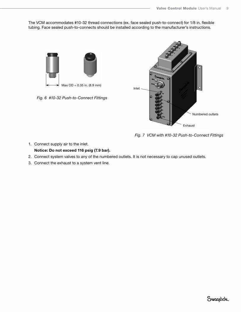
The VCM accommodates #10-32 thread connections (ex. face sealed push-to-connect) for 1/8 in. flexible tubing. Face sealed push-to-connects should be installed according to the manufacturer’s instructions.
1. Connect supply air to the inlet.
Notice: Do not exceed 116 psig (7 9 bar)
2. Connect system valves to any of the numbered outlets. It is not necessary to cap unused outlets.
3. Connect the exhaust to a system vent line.
Fig. 6 #10-32 Push-to-Connect Fittings
Fig. 7 VCM with #10-32 Push-to-Connect Fittings
Inlet
Numbered outlets
Exhaust
Max OD = 0.35 in. (8.9 mm)
10 Valve Control Module User’s Manual
Proximity SensorThe Swagelok VCM model number SS-VCM-D-6-2 is designed to work with the Bi 1-EG05-AP6X proximity sensor manufactured by Turck Inc. These sensors can be added as an option to the applicable Swagelok valve at the time of purchase. An alternate option is a compatible three-wire, 12 V (dc), PNP proximity sensor.
Note: The SS-VCM-D-6-0 model does not have any capability to interface with proximity sensors.
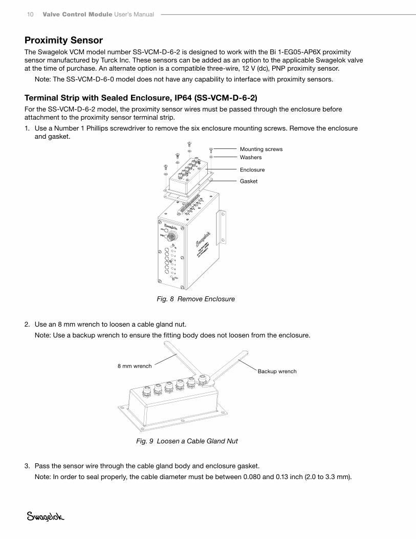
Terminal Strip with Sealed Enclosure, IP64 (SS-VCM-D-6-2)For the SS-VCM-D-6-2 model, the proximity sensor wires must be passed through the enclosure before attachment to the proximity sensor terminal strip.
1. Use a Number 1 Phillips screwdriver to remove the six enclosure mounting screws. Remove the enclosure and gasket.
2. Use an 8 mm wrench to loosen a cable gland nut.
Note: Use a backup wrench to ensure the fitting body does not loosen from the enclosure.
3. Pass the sensor wire through the cable gland body and enclosure gasket.
Note: In order to seal properly, the cable diameter must be between 0.080 and 0.13 inch (2.0 to 3.3 mm).
Fig. 9 Loosen a Cable Gland Nut
Backup wrench8 mm wrench
Fig. 8 Remove Enclosure
Mounting screws
Enclosure
Gasket
Washers
Valve Control Module User’s Manual 11
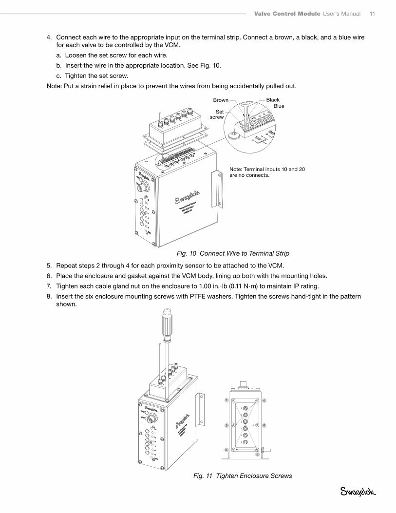
4. Connect each wire to the appropriate input on the terminal strip. Connect a brown, a black, and a blue wire for each valve to be controlled by the VCM.
a. Loosen the set screw for each wire.
b. Insert the wire in the appropriate location. See Fig. 10.
c. Tighten the set screw.
Note: Put a strain relief in place to prevent the wires from being accidentally pulled out.
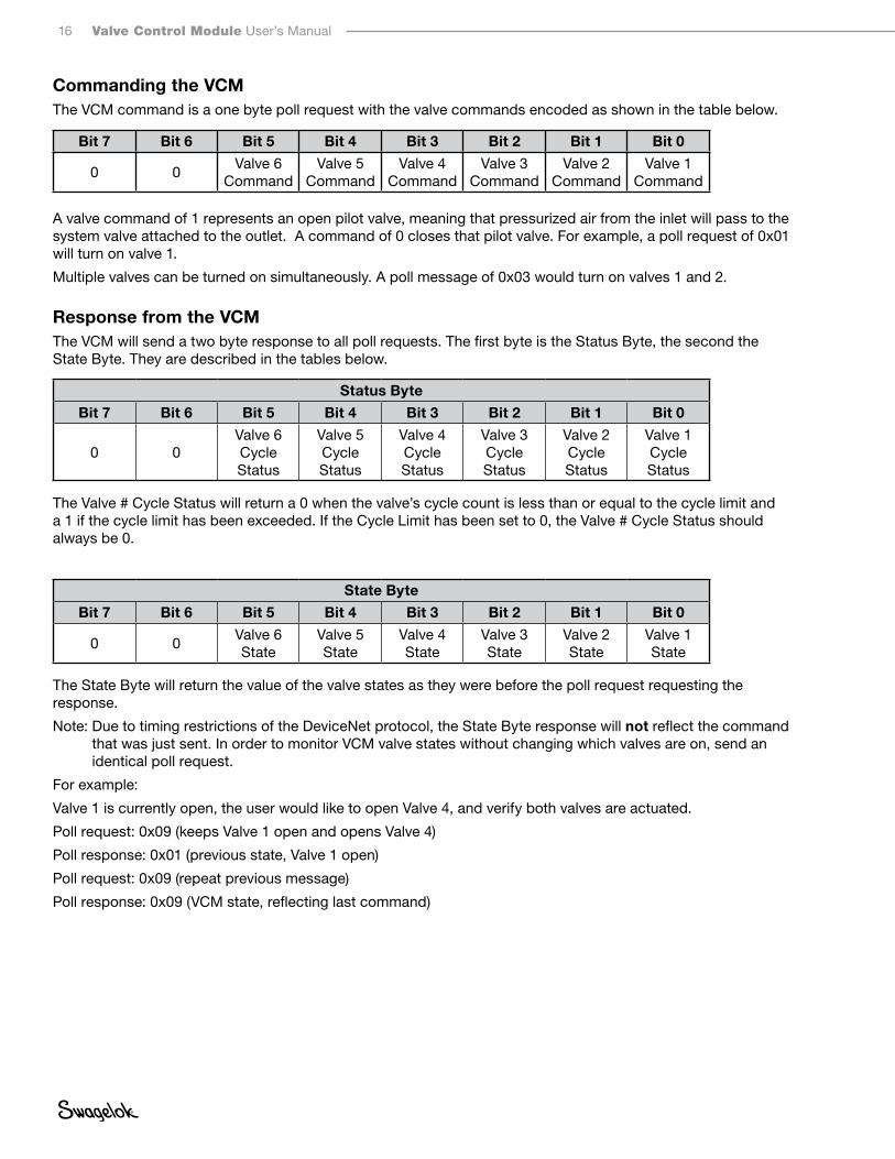
5. Repeat steps 2 through 4 for each proximity sensor to be attached to the VCM.
6. Place the enclosure and gasket against the VCM body, lining up both with the mounting holes.
7. Tighten each cable gland nut on the enclosure to 1.00 in. · lb (0.11 N · m) to maintain IP rating.
8. Insert the six enclosure mounting screws with PTFE washers. Tighten the screws hand-tight in the pattern shown.
Fig. 10 Connect Wire to Terminal Strip
Brown BlackBlue
Note: Terminal inputs 10 and 20 are no connects.
1
2
5
3
4
6
Fig. 11 Tighten Enclosure Screws
Set screw

12 Valve Control Module User’s Manual
9. Cap any unused cable glands using the caps and O-rings provided to maintain IP rating.
10. Remove the cable gland nut using a 8 mm wrench. Slide an O-ring onto the cable gland body until it is seated at the base of the threads.
11. Thread on a cap and tighten to 1.00 in. · lb (0.11 N · m) using a 10 mm wrench.
Setup Notice: The VCM must be disconnected from the system while performing setup functions
Electronic Data Sheet (EDS)1. Download the electronic data sheet (EDS) file from www swagelok com.
Note: Altering the EDS in any way voids the product warranty.
2. Open your network configuration tool, such as RSNetWorx™ for DeviceNet.
3. Register the EDS using the network configuration tool.
4. Connect the VCM to the network.
5. Scan the network for the VCM, and click on the device.
6. Use the network configuration tool to set the fields.
Fig 12 Cap and O-ring Assembly

Valve Control Module User’s Manual 13
General Tab
Device Address (MAC ID)The VCM will have a factory set address of 63 when initially powered on. Addresses between 0 and 63 are valid DeviceNet addresses. Do not duplicate addresses. Duplicate addresses will cause the devices at that address to be unable to communicate with the network. As noted, new devices will be set to address 63, so it is recommended to leave that address open to accommodate new hardware.
Assign higher priority devices a low network address as the lowest network address will be given priority during network arbitration.
Parameter TabThese fields can be set for each of the attached valves. Select the valve to edit and then the desired field(s).
Fig 14 Parameter Tab
Fig 13 General Tab

14 Valve Control Module User’s Manual
Fault and Idle ActionsThe VCM can be configured to go into a known state, or maintain its last commanded state, in the event of a Fault or Idle state. The dropdown options are:
■ Fault Value— The Fault Value parameter will determine whether the valve is turned on or off during a fault with a 1 indicating the valve will be on and a 0 indicating the valve is off.
■ Hold Last State—The valve will remain in the last commanded state in the event of a fault.
The Idle Action dropdown options are the same as the Fault Action dropdown options.
Cycle Count and LimitThe VCM will track how many cycles each valve has had since manufacture. In addition, the user can set the Cycle Limit field to send an alarm at a desired cycle count to plan for maintenance. Setting the Cycle Limit to 0 will make that function inoperative.
NOTE: The cycle count is stored to non-volatile memory each time the cycle count grows by more than 10%. It is not stored each and every time a valve is actuated.
Fig 15 Setting Fault Action
Fig 16 Cycle Count and Limit

Valve Control Module User’s Manual 15
Sensor ConfigurationThe Sensor Available field should be set to True when the valve has a proximity sensor attached. Valves without sensors set to False will provide feedback on the last commanded state. This field cannot be set for the SS-VCM-D-6-0 model but will still display on the screen.
Operation1. Connect the VCM to the system.
2. Verify the system air is on.
Fig 17 Sensor Available
Fig 18 SS-VCM-D-6-2 connected to a SSV series
16 Valve Control Module User’s Manual
Commanding the VCM The VCM command is a one byte poll request with the valve commands encoded as shown in the table below.
Bit 7 Bit 6 Bit 5 Bit 4 Bit 3 Bit 2 Bit 1 Bit 0
0 0Valve 6
CommandValve 5
CommandValve 4
CommandValve 3
CommandValve 2
CommandValve 1
Command
A valve command of 1 represents an open pilot valve, meaning that pressurized air from the inlet will pass to the system valve attached to the outlet. A command of 0 closes that pilot valve. For example, a poll request of 0x01 will turn on valve 1.
Multiple valves can be turned on simultaneously. A poll message of 0x03 would turn on valves 1 and 2.
Response from the VCMThe VCM will send a two byte response to all poll requests. The first byte is the Status Byte, the second the State Byte. They are described in the tables below.
Status Byte
Bit 7 Bit 6 Bit 5 Bit 4 Bit 3 Bit 2 Bit 1 Bit 0
0 0Valve 6 Cycle Status
Valve 5 Cycle Status
Valve 4 Cycle Status
Valve 3 Cycle Status
Valve 2 Cycle Status
Valve 1 Cycle Status
The Valve # Cycle Status will return a 0 when the valve’s cycle count is less than or equal to the cycle limit and a 1 if the cycle limit has been exceeded. If the Cycle Limit has been set to 0, the Valve # Cycle Status should always be 0.
State Byte
Bit 7 Bit 6 Bit 5 Bit 4 Bit 3 Bit 2 Bit 1 Bit 0
0 0Valve 6 State
Valve 5 State
Valve 4 State
Valve 3 State
Valve 2 State
Valve 1 State
The State Byte will return the value of the valve states as they were before the poll request requesting the response.
Note: Due to timing restrictions of the DeviceNet protocol, the State Byte response will not reflect the command that was just sent. In order to monitor VCM valve states without changing which valves are on, send an identical poll request.
For example:
Valve 1 is currently open, the user would like to open Valve 4, and verify both valves are actuated.
Poll request: 0x09 (keeps Valve 1 open and opens Valve 4)
Poll response: 0x01 (previous state, Valve 1 open)
Poll request: 0x09 (repeat previous message)
Poll response: 0x09 (VCM state, reflecting last command)

Valve Control Module User’s Manual 17
Note: The State Byte will return the value of the sensor if a valve is configured to use a proximity sensor. This means that the poll response may not be the same value as the command sent.
For example, when valve 1 is connected to a normally closed valve with a BI 1-EG05-AP6X sensor and is configured to accept sensor input, the response will look like:
Valve State
Valve Position
Sensor State
Valve Indicator Light Poll Response
Off Closed On On 1
On Open Off Off 0
MaintenanceThere are no field-maintainable parts within the VCM. Contact your authorized Swagelok representative for assistance.
The following hardware kit is available:
Enclosure Hardware Kit (MS-VCM-KIT1)
This kit contains the components used to attach and seal the interface cover included with the valve control module, SS-VCM-D-6-2. The contents of this kit are included with that model when shipped from the factory.
■ 6 screws
■ 6 washers
■ 1 interface cover gasket
■ 6 acorn nuts
■ 6 cable gland O-rings
■ 6 cable glands and nuts
Connector Kit (MS-VCM-KIT2)
This kit contains eight #10-32 face seal push-to-connect fittings for use when connecting 1/8 in. plastic tubing to the valve control module (VCM).
Fig 19 Valve Indicator Light
18 Valve Control Module User’s Manual
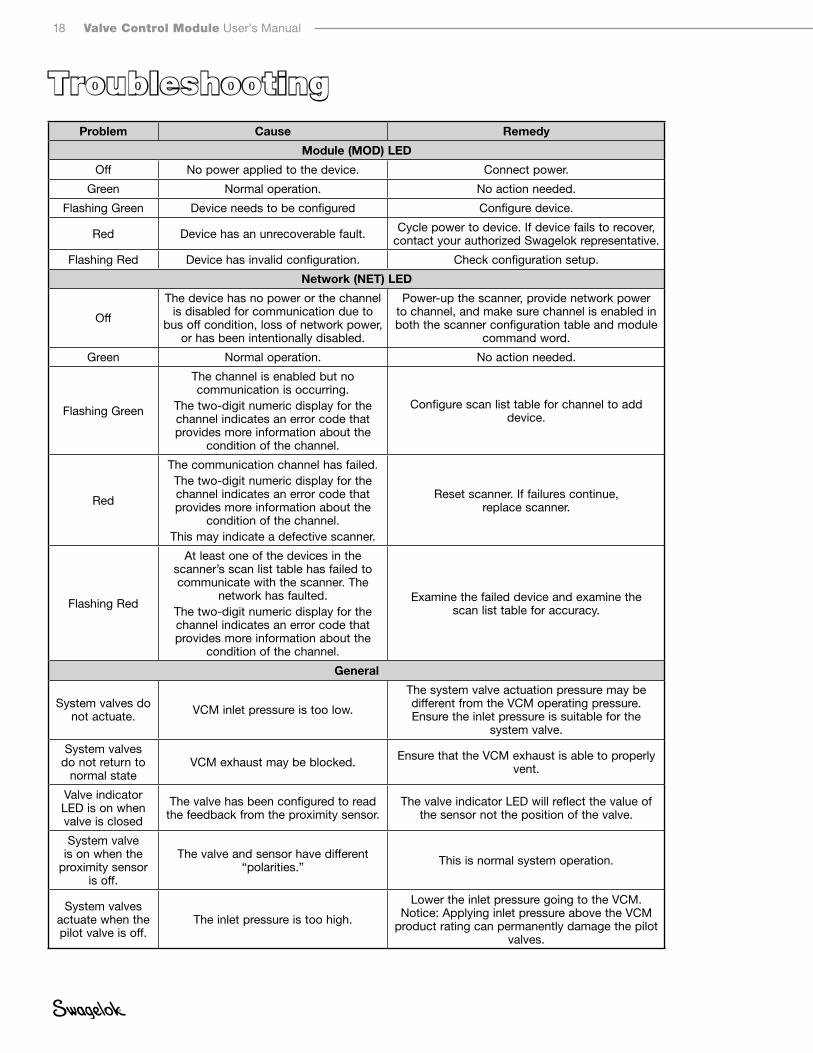
TroubleshootingProblem Cause Remedy
Module (MOD) LED
Off No power applied to the device. Connect power.
Green Normal operation. No action needed.
Flashing Green Device needs to be configured Configure device.
Red Device has an unrecoverable fault. Cycle power to device. If device fails to recover, contact your authorized Swagelok representative.
Flashing Red Device has invalid configuration. Check configuration setup.
Network (NET) LED
Off
The device has no power or the channel is disabled for communication due to
bus off condition, loss of network power, or has been intentionally disabled.
Power-up the scanner, provide network power to channel, and make sure channel is enabled in both the scanner configuration table and module
command word.
Green Normal operation. No action needed.
Flashing Green
The channel is enabled but no communication is occurring.
The two-digit numeric display for the channel indicates an error code that provides more information about the
condition of the channel.
Configure scan list table for channel to add device.
Red
The communication channel has failed.The two-digit numeric display for the channel indicates an error code that provides more information about the
condition of the channel.This may indicate a defective scanner.
Reset scanner. If failures continue, replace scanner.
Flashing Red
At least one of the devices in the scanner’s scan list table has failed to communicate with the scanner. The
network has faulted.The two-digit numeric display for the channel indicates an error code that provides more information about the
condition of the channel.
Examine the failed device and examine the scan list table for accuracy.
General
System valves do not actuate. VCM inlet pressure is too low.
The system valve actuation pressure may be different from the VCM operating pressure. Ensure the inlet pressure is suitable for the
system valve.
System valves do not return to
normal stateVCM exhaust may be blocked. Ensure that the VCM exhaust is able to properly
vent.
Valve indicator LED is on when valve is closed
The valve has been configured to read the feedback from the proximity sensor.
The valve indicator LED will reflect the value of the sensor not the position of the valve.
System valve is on when the
proximity sensor is off.
The valve and sensor have different “polarities.” This is normal system operation.
System valves actuate when the pilot valve is off.
The inlet pressure is too high.
Lower the inlet pressure going to the VCM. Notice: Applying inlet pressure above the VCM
product rating can permanently damage the pilot valves.
Valve Control Module User’s Manual 19
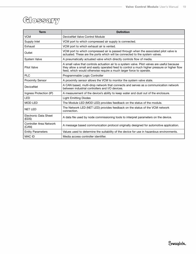
GlossaryTerm Definition
VCM DeviceNet Valve Control Module
Supply Inlet VCM port to which compressed air supply is connected.
Exhaust VCM port to which exhaust air is vented.
Outlet VCM port to which compressed air is passed through when the associated pilot valve is actuated. These are the ports which will be connected to the system valves.
System Valve A pneumatically actuated valve which directly controls flow of media.
Pilot ValveA small valve that controls actuation air to a system valve. Pilot valves are useful because they allow a small and easily operated feed to control a much higher pressure or higher flow feed, which would otherwise require a much larger force to operate.
PLC Programmable Logic Controller
Proximity Sensor A proximity sensor allows the VCM to monitor the system valve state.
DeviceNet A CAN based, multi-drop network that connects and serves as a communication network between industrial controllers and I/O devices.
Ingress Protection (IP) A measurement of the device’s ability to keep water and dust out of the enclosure.
LED Light Emitting Diodes
MOD LED The Module LED (MOD LED) provides feedback on the status of the module.
NET LED The Network LED (NET LED) provides feedback on the status of the VCM network connection.
Electronic Data Sheet (EDS) A data file used by node commissioning tools to interpret parameters on the device.
Controller Area Network (CAN) A message based communication protocol originally designed for automotive application.
Entity Parameters Values used to determine the suitability of the device for use in hazardous environments.
MAC ID Media access controller identifier.

Swagelok—TM Swagelok CompanyDeviceNet—TM ODVARSNetWorx—TM Rockwell Automation, Inc.© 2012-2019 Swagelok CompanyDecember 2019, RevAMS-13-221
Top Related