ZXDU CSU500 (SV1.01) Centralized Supervision Unit Parameter and Alarm Setting
20
ZXDU CSU500 Centralized Supervision Unit Parameter and Alarm Setting Version: SV1.01 ZTE CORPORATION NO. 55, Hi-tech Road South, ShenZhen, P.R.China Postcode: 518057 Tel: +86-755-26771900 Fax: +86-755-26770801 URL: http://ensupport.zte.com.cn E-mail: [email protected]
-
Upload
jose-luis-gonzalez -
Category
Documents
-
view
1.068 -
download
160
Transcript of ZXDU CSU500 (SV1.01) Centralized Supervision Unit Parameter and Alarm Setting

ZXDU CSU500Centralized Supervision Unit
Parameter and Alarm Setting
Version: SV1.01
ZTE CORPORATIONNO. 55, Hi-tech Road South, ShenZhen, P.R.ChinaPostcode: 518057Tel: +86-755-26771900Fax: +86-755-26770801URL: http://ensupport.zte.com.cnE-mail: [email protected]

LEGAL INFORMATIONCopyright © 2011 ZTE CORPORATION.
The contents of this document are protected by copyright laws and international treaties. Any reproduction or
distribution of this document or any portion of this document, in any form by any means, without the prior written
consent of ZTE CORPORATION is prohibited. Additionally, the contents of this document are protected by
contractual confidentiality obligations.
All company, brand and product names are trade or service marks, or registered trade or service marks, of ZTE
CORPORATION or of their respective owners.
This document is provided “as is”, and all express, implied, or statutory warranties, representations or conditions
are disclaimed, including without limitation any implied warranty of merchantability, fitness for a particular purpose,
title or non-infringement. ZTE CORPORATION and its licensors shall not be liable for damages resulting from the
use of or reliance on the information contained herein.
ZTE CORPORATION or its licensors may have current or pending intellectual property rights or applications
covering the subject matter of this document. Except as expressly provided in any written license between ZTE
CORPORATION and its licensee, the user of this document shall not acquire any license to the subject matter
herein.
ZTE CORPORATION reserves the right to upgrade or make technical change to this product without further notice.
Users may visit ZTE technical support website http://ensupport.zte.com.cn to inquire related information.
The ultimate right to interpret this product resides in ZTE CORPORATION.
Revision History
Revision No. Revision Date Revision Reason
R1.0 2012-06-11 First edition
Serial Number: SJ-20120514092538-008
Publishing Date: 2012-06-11 (R1.0)

ContentsChapter 1 Setting Parameters ................................................................... 1-1
1.1 Parameters That Need to Be Set on Site ............................................................. 1-1
1.2 Modifying Parameters......................................................................................... 1-3
Chapter 2 Settıng Alarm............................................................................. 2-12.1 Alarm Information............................................................................................... 2-1
2.2 Setting the Level and Output Relay for an Alarm .................................................. 2-9
2.3 Setting Attributes for an Input Relay................................................................... 2-10
Glossary .......................................................................................................... I
I

II

Chapter 1Setting ParametersTable of Contents
Parameters That Need to Be Set on Site....................................................................1-1Modifying Parameters ................................................................................................1-3
1.1 Parameters That Need to Be Set on SiteAll parameters are pre-configured before delivery except the following information, whichcannot be predicted. These user-defined parameters should be checked and set properlyduring installation.
l Different types of batteriesl On-site local time
For a description of the setting requirements for user-defined parameters, refer toTable1-1.
Table 1-1 Parameters That Need to Be Set on Site
Parameter DefaultValue
ModifiedValue
Setting Requirement
System parametersMenu path: Para.Set > System Para.
Battery Cap.-1# 300 Ah
Battery Cap.-2# 300 Ah
Battery Cap.-3# 0 Ah
Battery Cap.-4# 0 Ah
Set the four parameters according to actual capacity of each
battery branch.
For example, if the battery branch 1 is equipped with a 300 Ah
battery pack, set Battery Cap.-1# to 300 Ah. If the battery branch1 is equipped with two 100 Ah battery packs that are connected
in parallel, set Battery Cap.-1# to 200 Ah, which is the sum of
two battery packs.
Caution: If a battery branch is equipped with no battery, set thecorresponding battery capacity to “0”. An incorrect battery capacity
setting will cause the CSU to fail to manage the batteries.
Port Baudrate 9600 In the networking mode through the serial port, set the parameter
according to the actual baud rate.
Remote IP-1# 0.0.0.0
Remote IP-2# 0.0.0.0
Remote IP-3# 0.0.0.0
In the networking mode through the RJ45 Ethernet interface using
NE-layer protocol or 1104 protocol, set each parameter according
to actual IP address of the computer with the NMS software
installed.
1-1
SJ-20120514092538-008|2012-06-11 (R1.0) ZTE Proprietary and Confidential

ZXDU CSU500 Parameter and Alarm Setting
Parameter DefaultValue
ModifiedValue
Setting Requirement
Remote Port-1# 0
Remote Port-2# 0
Remote Port-3# 0
In the networking mode through the RJ45 Ethernet interface using
NE-layer protocol or 1104 protocol, set each parameter according
to actual port of the computer with the NMS software installed.
Battery parametersMenu path: Para.Set > Batt.Para.
Float Voltage 53.5 V Float charging voltage of battery packs, set this parameter
according to the battery charging characteristics.
Equalized Voltage 56.4 V Equalized charging voltage of battery packs, set this parameter
according to the battery charging characteristics.
Chg.Curr.Coeff. 0.15 C10 Charging current coefficient, set this parameter according to the
battery charging characteristics.
Local setting parametersMenu path: Local Set > System Time
System Time - Modified according to local time of the equipment installation
site, to ensure system validity of regular management and timing
information.
Local setting parametersMenu path: Local Set > NetworkIn the networking mode through the RJ45 Ethernet interface, follow the instructions:
Local IP Mode Dynamic It is recommended to use the default. When Local IP Modeis Dynamic, Local IP, Mask and Gateway are allocated
automatically, so users do not need to set the three parameters.
Local IP 010.009.0
85.013
When Local IP Mode is Static, set the parameter to the actualIP address.
Mask 255.255.2
55.128
When Local IP Mode is Static, set the parameter to the actualmask.
Gateway 010.009.0
85.001
When Local IP Mode is Static, set the parameter to the actualgateway IP address.
SNMP parameters
Menu path: Para.Set > SNMP Para.
1-2
SJ-20120514092538-008|2012-06-11 (R1.0) ZTE Proprietary and Confidential
Chapter 1 Setting Parameters
Parameter DefaultValue
ModifiedValue
Setting Requirement
In the networking mode through the serial port or through the RJ45
Ethernet interface using NE-layer protocol or 1104 protocol, follow
the instructions:
Set the parameter to 0.0.0.0.
Caution: After resuming to default setting (Load Cfg.Para),manually set the parameter to 0.0.0.0.
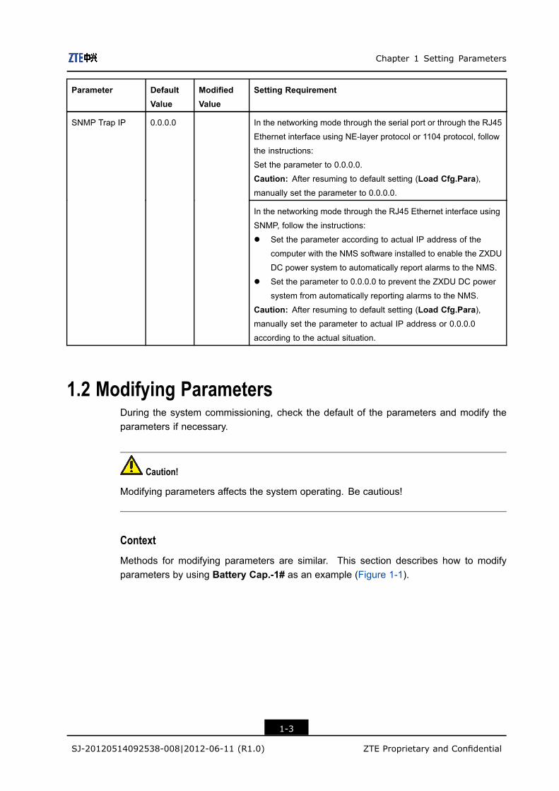
SNMP Trap IP 0.0.0.0
In the networking mode through the RJ45 Ethernet interface using
SNMP, follow the instructions:
l Set the parameter according to actual IP address of the
computer with the NMS software installed to enable the ZXDU
DC power system to automatically report alarms to the NMS.
l Set the parameter to 0.0.0.0 to prevent the ZXDU DC power
system from automatically reporting alarms to the NMS.
Caution: After resuming to default setting (Load Cfg.Para),manually set the parameter to actual IP address or 0.0.0.0
according to the actual situation.
1.2 Modifying ParametersDuring the system commissioning, check the default of the parameters and modify theparameters if necessary.
Caution!
Modifying parameters affects the system operating. Be cautious!
Context
Methods for modifying parameters are similar. This section describes how to modifyparameters by using Battery Cap.-1# as an example (Figure 1-1).
1-3
SJ-20120514092538-008|2012-06-11 (R1.0) ZTE Proprietary and Confidential

ZXDU CSU500 Parameter and Alarm Setting
Figure 1-1 Modifying Parameters
Steps
1. Select Para.Set from the main menu and press Ent. The password screen isdisplayed.
2. Enter the password (the initial password is 0000).
The password-entering methods are as follows:
l Press ▲ or ▼ to modify values.l Press ► or ◄ to move the cursor.
3. Press Ent. The Para.Set screen is displayed.
4. Press▲ or▼ to select a parameter type. For example, select System Para.
5. Press Ent. The submenus of System Para. are displayed.
6. Press▲ or▼ to select a parameter to modify. For example, select Battery Cap.-1#.
7. Press Ent. The modification screen is displayed.
8. Modify the selected parameter.
The parameter-modifying methods are as follows:
l Press ▲ or ▼ to modify values.l Press ► or ◄ to move the cursor.
9. After modification, press Ent to save it.
10. Press Esc to return to the upper-level screens and to return to the main menu screen.
– End of Steps –
1-4
SJ-20120514092538-008|2012-06-11 (R1.0) ZTE Proprietary and Confidential
Chapter 2Settıng AlarmTable of Contents
Alarm Information.......................................................................................................2-1Setting the Level and Output Relay for an Alarm ........................................................2-9Setting Attributes for an Input Relay .........................................................................2-10
2.1 Alarm InformationThis section describes alarm prompts and alarm attributes.
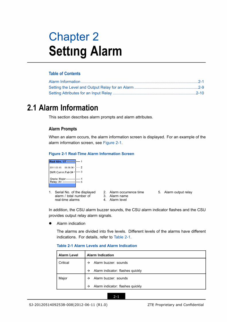
Alarm PromptsWhen an alarm occurs, the alarm information screen is displayed. For an example of thealarm information screen, see Figure 2-1.
Figure 2-1 Real-Time Alarm Information Screen
1. Serial No. of the displayedalarm / total number ofreal-time alarms
2. Alarm occurrence time3. Alarm name4. Alarm level
5. Alarm output relay
In addition, the CSU alarm buzzer sounds, the CSU alarm indicator flashes and the CSUprovides output relay alarm signals.
l Alarm indication
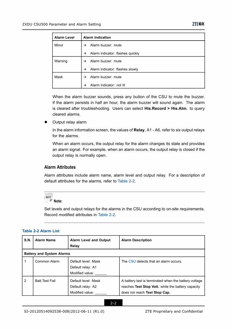
The alarms are divided into five levels. Different levels of the alarms have differentindications. For details, refer to Table 2-1.
Table 2-1 Alarm Levels and Alarm Indication
Alarm Level Alarm Indication
Critical à Alarm buzzer: sounds
à Alarm indicator: flashes quickly
Major à Alarm buzzer: sounds
à Alarm indicator: flashes quickly
2-1
SJ-20120514092538-008|2012-06-11 (R1.0) ZTE Proprietary and Confidential
ZXDU CSU500 Parameter and Alarm Setting
Alarm Level Alarm Indication
Minor à Alarm buzzer: mute
à Alarm indicator: flashes quickly
Warning à Alarm buzzer: mute
à Alarm indicator: flashes slowly
Mask à Alarm buzzer: mute
à Alarm indicator: not lit
When the alarm buzzer sounds, press any button of the CSU to mute the buzzer.If the alarm persists in half an hour, the alarm buzzer will sound again. The alarmis cleared after troubleshooting. Users can select His.Record > His.Alm. to querycleared alarms.
l Output relay alarm
In the alarm information screen, the values of Relay, A1 - A6, refer to six output relaysfor the alarms.
When an alarm occurs, the output relay for the alarm changes its state and providesan alarm signal. For example, when an alarm occurs, the output relay is closed if theoutput relay is normally open.
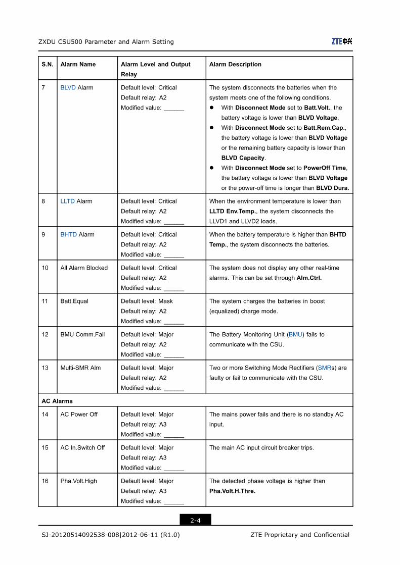
Alarm AttributesAlarm attributes include alarm name, alarm level and output relay. For a description ofdefault attributes for the alarms, refer to Table 2-2.
Note:
Set levels and output relays for the alarms in the CSU according to on-site requirements.Record modified attributes in Table 2-2.
Table 2-2 Alarm List
S.N. Alarm Name Alarm Level and OutputRelay
Alarm Description
Battery and System Alarms
1 Common Alarm Default level: Mask
Default relay: A1
Modified value: ______
The CSU detects that an alarm occurs.
2 Batt.Test Fail Default level: Mask
Default relay: A2
Modified value: ______
A battery test is terminated when the battery voltage
reaches Test Stop Volt. while the battery capacitydoes not reach Test Stop Cap.
2-2
SJ-20120514092538-008|2012-06-11 (R1.0) ZTE Proprietary and Confidential

Chapter 2 Settıng Alarm
S.N. Alarm Name Alarm Level and OutputRelay
Alarm Description
3 LLVD1 Alarm Default level: Critical
Default relay: A2
Modified value: ______
The system disconnects the LLVD1 loads (secondary
loads) when the system meets one of the following
conditions.
l With Disconnect Mode set to Batt.Volt., thebattery voltage is lower than LLVD1 Voltage.
l With Disconnect Mode set to Batt.Rem.Cap.,the battery voltage is lower than LLVD1 Voltageor the remaining battery capacity is lower than
LLVD1 Capacity.l With Disconnect Mode set to PowerOff Time,
the battery voltage is lower than LLVD1 Voltageor the power-off time is longer than LLVD1Duration.
4 LLVD2 Alarm Default level: Critical
Default relay: A2
Modified value: ______
The system disconnects the LLVD2 loads (primary
loads) when the system meets one of the following
conditions.
l With Disconnect Mode set to Batt.Volt., thebattery voltage is lower than LLVD2 Voltage.
l With Disconnect Mode set to Batt.Rem.Cap.,the battery voltage is lower than LLVD2 Voltageor the remaining battery capacity is lower than
LLVD2 Capacity.l With Disconnect Mode set to PowerOff Time,
the battery voltage is lower than LLVD2 Voltageor the power-off time is longer than LLVD2Duration.
5 CAN Bus Abnormal Default level: Mask
Default relay: A2
Modified value: ______
The CAN bus cannot send or receive data normally
due to some communication error.
6 Batt.Det.Abnor. Default level: Critical
Default relay: A2
Modified value: ______
The battery voltage is lower than Test Stop Volt. inthe process of the battery test.
2-3
SJ-20120514092538-008|2012-06-11 (R1.0) ZTE Proprietary and Confidential
ZXDU CSU500 Parameter and Alarm Setting
S.N. Alarm Name Alarm Level and OutputRelay
Alarm Description
7 BLVD Alarm Default level: Critical
Default relay: A2
Modified value: ______
The system disconnects the batteries when the
system meets one of the following conditions.
l With Disconnect Mode set to Batt.Volt., thebattery voltage is lower than BLVD Voltage.
l With Disconnect Mode set to Batt.Rem.Cap.,the battery voltage is lower than BLVD Voltageor the remaining battery capacity is lower than
BLVD Capacity.l With Disconnect Mode set to PowerOff Time,
the battery voltage is lower than BLVD Voltageor the power-off time is longer than BLVD Dura.
8 LLTD Alarm Default level: Critical
Default relay: A2
Modified value: ______
When the environment temperature is lower than
LLTD Env.Temp., the system disconnects the
LLVD1 and LLVD2 loads.
9 BHTD Alarm Default level: Critical
Default relay: A2
Modified value: ______
When the battery temperature is higher than BHTDTemp., the system disconnects the batteries.
10 All Alarm Blocked Default level: Critical
Default relay: A2
Modified value: ______
The system does not display any other real-time
alarms. This can be set through Alm.Ctrl.
11 Batt.Equal Default level: Mask
Default relay: A2
Modified value: ______
The system charges the batteries in boost
(equalized) charge mode.
12 BMU Comm.Fail Default level: Major
Default relay: A2
Modified value: ______
The Battery Monitoring Unit (BMU) fails to
communicate with the CSU.
13 Multi-SMR Alm Default level: Major
Default relay: A2
Modified value: ______
Two or more Switching Mode Rectifiers (SMRs) are
faulty or fail to communicate with the CSU.
AC Alarms
14 AC Power Off Default level: Major
Default relay: A3
Modified value: ______
The mains power fails and there is no standby AC
input.
15 AC In.Switch Off Default level: Major
Default relay: A3
Modified value: ______
The main AC input circuit breaker trips.
16 Pha.Volt.High Default level: Major
Default relay: A3
Modified value: ______
The detected phase voltage is higher than
Pha.Volt.H.Thre.
2-4
SJ-20120514092538-008|2012-06-11 (R1.0) ZTE Proprietary and Confidential

Chapter 2 Settıng Alarm
S.N. Alarm Name Alarm Level and OutputRelay
Alarm Description
17 Pha.Volt.Low Default level: Major
Default relay: A3
Modified value: ______
The detected phase voltage is lower than PhaseUnder Volt.
18 AC Phase Lack Default level: Major
Default relay: A3
Modified value: ______
The AC input lacks one phase or two.
19 Pha.Volt.Imbala Default level: Major
Default relay: A3
Modified value: ______
The difference between phase voltages is greater
than Phase Volt.Imbala.
20 Pha.Curr.High Default level: Major
Default relay: A3
Modified value: ______
The phase current is higher than AC Curr.High.Thre.
21 AC Out.Switch Off Default level: Major
Default relay: A3
Modified value: ______
The auxiliary AC output circuit breaker trips.
22 AC SPD Abnor Default level: Major
Default relay: A3
Modified value: ______
The AC Surge Protection Device (SPD) is damaged
or not installed.
Rectifier Alarms
23 SMR Fan Fault Default level: Major
Default relay: A4
Modified value: ______
The rectifier fan is faulty.
24 SMR Ra.T.H.O Default level: Major
Default relay: A4
Modified value: ______
The temperature of the PFC heat radiator is higher
than the maximum radiator temperature (110 ℃).
25 SMR In.V.H.O. Default level: Major
Default relay: A4
Modified value: ______
The AC input voltage of the rectifier is higher than
the maximum input voltage (300 V).
26 SMR In.V.L.O. Default level: Major
Default relay: A4
Modified value: ______
The AC input voltage of the rectifier is lower than the
minimum input voltage (80 V).
27 SMR Out.V.H.O. Default level: Major
Default relay: A4
Modified value: ______
The output voltage of the rectifier is higher than the
maximum output voltage (56.6 V to 62 V, which can
be set).
28 SMR Out.C.H. Default level: Major
Default relay: A4
Modified value: ______
The output current of the rectifier is higher than the
maximum output current (68 A).
2-5
SJ-20120514092538-008|2012-06-11 (R1.0) ZTE Proprietary and Confidential

ZXDU CSU500 Parameter and Alarm Setting
S.N. Alarm Name Alarm Level and OutputRelay
Alarm Description
29 SMR Inter.T.H. Default level: Major
Default relay: A4
Modified value: ______
The temperature at the air inlet of the rectifier is
higher than the maximum internal temperature (70
℃).
30 SMR Out.Fuse Default level: Major
Default relay: A4
Modified value: ______
The output fuse of the rectifier blows.
31 SMR Curr.Share Default level: Major
Default relay: A4
Modified value: ______
When multiple rectifiers are working in parallel, the
output current difference between these rectifiers is
greater than the threshold (8 A).
32 SMR Input Off Default level: Major
Default relay: A4
Modified value: ______
The power input of the rectifier is interrupted.
33 PFC Out.V.H. Default level: Major
Default relay: A4
Modified value: ______
The output voltage of PFC is higher than the
threshold (450 V).
34 PFC Out.V.L. Default level: Major
Default relay: A4
Modified value: ______
The output voltage of PFC is lower than the threshold
(345 V).
35 SMR EEPROM Default level: Major
Default relay: A4
Modified value: ______
Errors occur when the rectifier reads and writes the
EEPROM.
36 SMR In.Comm F. Default level: Major
Default relay: A4
Modified value: ______
The communication inside the rectifier fails.
37 SMR Primy.C.H. Default level: Major
Default relay: A4
Modified value: ______
The primary current of the transformer is higher than
the threshold (28 A).
38 PFC Input C.H. Default level: Major
Default relay: A4
Modified value: ______
Reserved alarm
39 SMR Start Abr. Default level: Major
Default relay: A4
Modified value: ______
The starting time of the rectifier exceeds 5 minutes.
40 SMR In.Fuse Default level: Major
Default relay: A4
Modified value: ______
The input fuse of the rectifier blows.
2-6
SJ-20120514092538-008|2012-06-11 (R1.0) ZTE Proprietary and Confidential

Chapter 2 Settıng Alarm
S.N. Alarm Name Alarm Level and OutputRelay
Alarm Description
41 SMR Comm.Fail Default level: Major
Default relay: A4
Modified value: ______
The communication between the rectifier and the
CSU is interrupted because the rectifier is removed
or there is some communication exception.
42 SMR In.Freq. Default level: Major
Default relay: A4
Modified value: ______
The input frequency of the rectifier is too high (higher
than 73 Hz) or too low (lower than 40 Hz).
43 SMR Out.V.L. Default level: Major
Default relay: A4
Modified value: ______
The output voltage of the rectifier is lower than the
threshold (36 V).
DC Alarms
44 DC Volt.High Default level: Major
Default relay: A5
Modified value: ______
The DC output voltage is higher than DC Volt.HighThre.
45 DC Volt.Low Default level: Major
Default relay: A5
Modified value: ______
The DC output voltage is lower than DC Volt.LowThre.
46 DC SPD Abnor. Default level: Major
Default relay: A5
Modified value: ______
The DC SPD is faulty.
47 Batt.Volt.Low Default level: Major
Default relay: A5
Modified value: ______
The voltage of a battery pack is lower than
Batt.Volt.L.Thre.
48 Batt.Curr.Abr. Default level: Minor
Default relay: A5
Modified value: ______
The rate of the detected battery current to
the highest detectable current is greater than
Batt.Curr.Abn.Rate.
49 Batt.Temp.High Default level: Major
Default relay: A5
Modified value: ______
The battery temperature is higher than
Batt.Temp.H.Thre.
50 Batt.Temp.Low Default level: Major
Default relay: A5
Modified value: ______
The battery temperature is lower than
Batt.Temp.L.Thre.
51 Batt.Loop Brk. Default level: Critical
Default relay: A5
Modified value: ______
The battery loop is disconnected.
52 Batt.Dischg. Default level: Minor
Default relay: A5
Modified value: ______
The battery discharging current is higher than
Batt.Dischg Thre.
2-7
SJ-20120514092538-008|2012-06-11 (R1.0) ZTE Proprietary and Confidential

ZXDU CSU500 Parameter and Alarm Setting
S.N. Alarm Name Alarm Level and OutputRelay
Alarm Description
53 Batt.T.Invalid Default level: Warning
Default relay: A5
Modified value: ______
The system is configured with batteries, but the
battery temperature detection is ineffective. The
battery temperature sensor is not installed or the
battery temperature is out of the detection range.
54 LLVD1 Extend Brk. Default level: Major
Default relay: A5
Modified value: ______
The circuit breaker or fuse of the extended LLVD1
loop trips or blows.
55 LLVD1 Loop B. Default level: Major
Default relay: A5
Modified value: ______
The circuit breaker or fuse of the LLVD1 loop trips
or blows.
56 LLVD2 Extend Brk. Default level: Major
Default relay: A5
Modified value: ______
The circuit breaker or fuse of the extended LLVD2
loop trips or blows.
57 BLVD Extend Brk. Default level: Major
Default relay: A5
Modified value: ______
The fuse of the extended BLVD loop blows.
58 BLVD Loop Brk. Default level: Major
Default relay: A5
Modified value: ______
The fuse of the BLVD loop blows.
59 Cell Reverse Default level: Major
Default relay: No
Modified value: ______
One or more 2V batteries are reversely connected.
60 Block Reverse Default level: Major
Default relay: No
Modified value: ______
One or more 12V batteries are reversely connected.
61 Cell Poor Default level: Major
Default relay: No
Modified value: ______
The voltage of one or more 2V batteries is lower
than Cell Volt.Diff.
62 Block Poor Default level: Major
Default relay: No
Modified value: ______
The voltage of one or more 12V batteries is lower
than Block Volt.Diff.
Environment Alarms
63 Env.Temp.High Default level: Minor
Default relay: A6
Modified value: ______
The environment temperature is higher than
Env.Temp.H.Thre.
64 Env.Temp.Low Default level: Minor
Default relay: A6
Modified value: ______
The environment temperature is lower than
Env.Temp.L.Thre.
2-8
SJ-20120514092538-008|2012-06-11 (R1.0) ZTE Proprietary and Confidential

Chapter 2 Settıng Alarm
S.N. Alarm Name Alarm Level and OutputRelay
Alarm Description
65 Env.Hum.High Default level: Minor
Default relay: A6
Modified value: ______
The environment humidity is higher than
Env.Hum.H.Thre.
66 Env.Hum.Low Default level: Minor
Default relay: A6
Modified value: ______
The environment humidity is lower than
Env.Hum.L.Thre.
67 Smog Alarm Default level: Major
Default relay: A6
Modified value: ______
The sensor detects smog.
68 Flood Alarm Default level: Major
Default relay: A6
Modified value: ______
The sensor detects flood.
69 Access Ctrl.Alm. Default level: Minor
Default relay: A6
Modified value: ______
The sensor detects the intrusion of something.
70 Door Alarm Default level: Mask
Default relay: A6
Modified value: ______
The door with the door status switch is opened.
71 Glass Brk.Alm. Default level: Minor
Default relay: A6
Modified value: ______
The sensor detects broken glasses.
72 Env.Temp.Invalid Default level: Mask
Default relay: A6
Modified value: ______
The environment temperature sensor is damaged
or not installed.
73 Env.Hum.Invalid Default level: Mask
Default relay: A6
Modified value: ______
The environment humidity sensor is damaged or not
installed.
2.2 Setting the Level and Output Relay for an AlarmDuring the system commissioning, check the default levels and output relays for the alarmsand modify them if necessary.
Context
To set the level and output relay for an alarm, users need to select Para.Set > Alm.Attr.first. For the operations, see Figure 2-2.
2-9
SJ-20120514092538-008|2012-06-11 (R1.0) ZTE Proprietary and Confidential

ZXDU CSU500 Parameter and Alarm Setting
Figure 2-2 Setting the Level and Output Relay for an Alarm
• This image is for referenceonly. The actual screenmay differ.
Steps
1. Select Para.Set > Alm.Attr.
2. Press ▲ or ▼ to select the alarm to be set.
3. Press Ent.
4. Select Grade or Relay and press Ent. The modification screen is displayed.
5. Press ▲ or ▼ to select an alarm level or output relay.
6. Press Ent to save the setting.
7. Press Esc to return to the upper-level screens and to return to the main menu screen.
– End of Steps –
2.3 Setting Attributes for an Input RelayDuring the system commissioning, check the default attributes for the input relays andmodify the attributes if necessary.
2-10
SJ-20120514092538-008|2012-06-11 (R1.0) ZTE Proprietary and Confidential

Chapter 2 Settıng Alarm
Context
Users can set the following attributes for an input relay:
l Statel Gradel Name
To set these attributes, users need to select Para.Set > In-Relay Attr. first. For thefollow-up operations, see Figure 2-3.
Figure 2-3 Setting the Attributes for an Input Relay
Steps
1. Select Para.Set > In-Relay Attr. and press Ent. The In-Relay Attr. screen isdisplayed.
2. Press ▲ or ▼ to select the input relay to be set. For example, In-Relay Attr.-2# isselected in Figure 2-3.
3. Press Ent.
4. Select an attribute item and press Ent. The modification screen for the selected itemis displayed.
Modifying methods:
l For Grade and State, press ▲ or ▼ to select a value.l For Name, press▲ or▼ to change letters and press► or◄ to move the cursor.
5. Press Ent to save the setting.
6. Press Esc to return to the upper-level screens and to return to the main menu screen.
– End of Steps –
2-11
SJ-20120514092538-008|2012-06-11 (R1.0) ZTE Proprietary and Confidential

GlossaryBHTD- Battery High Temperature Disconnect
BLVD- Battery Low Voltage Disconnect
BMU- Battery Monitoring Unit
CSU- Centralized Supervision Unit
LLTD- Load Low Temperature Disconnect
LLVD- Load Low Voltage Disconnect
NMS- Network Management System
PFC- Power Factor Correction
SMR- Switching Mode Rectifier
SPD- Surge Protection Device
I