ZPHA Installation Guide - Trend Micro
16
Part Number: APEM07687/170111 TippingPoint Zero Power High Availability Installation Guide Modular and Non-modular
Transcript of ZPHA Installation Guide - Trend Micro

Part Number: APEM07687/170111
TippingPoint
Zero Power High Availability Installation GuideModular and Non-modular
Privacy and Personal Data Collection Disclosure
Certain features available in Trend Micro products collect and send feedback regarding product usage and detection information to Trend Micro. Some of this data is considered personal in certain jurisdictions and under certain regulations. If you do not want Trend Micro to collect personal data, you must ensure that you disable the related features.
The following link outlines the types of data that the Security Management System collects and provides detailed instructions on how to disable the specific features that feedback the information.
Legal Notice
© Copyright 2018 Trend Micro Incorporated. All rights reserved.
Trend Micro, the Trend Micro t-ball logo, TippingPoint, and Digital Vaccine are trademarks or registered trademarks of Trend Micro Incorporated. All other product or company names may be trademarks or registered trademarks of their owners.
Publication: December 2018
Data collected by Trend Micro is subject to the conditions stated in the Trend Micro Privacy Policy:
https://success.trendmicro.com/data-collection-disclosure
https://www.trendmicro.com/en_us/about/legal/privacy-policy-product.html
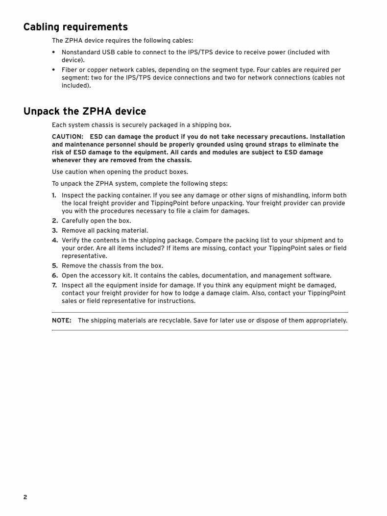
Prepare the siteBefore installing the ZPHA device, refer to all the site safety and compliance requirements in the TippingPoint Hardware Safety and Compliance Guide, in addition to the requirements that follow.
• “Ventilation and location” on page 1
• “Power requirements” on page 1
• “System grounding requirements” on page 1
• “Cabling requirements” on page 2
• “Unpack the ZPHA device” on page 2
Ventilation and locationVentilation and proper location are essential to the proper operation of the product. Follow these guidelines to ensure that the product receives adequate ventilation.
• The ZPHA device should be located near the IPS or TPS device in the rack. The ZPHA device connects to the IPS/TPS device through the following:
• Nonstandard USB cable for power
• Network cables to receive and transmit network traffic
• Do not connect a single ZPHA device to more than one IPS or TPS device with the nonstandard USB power cable. The ZPHA device requires only one USB connection for power.
Power requirements The TippingPoint ZPHA device receives power through a nonstandard USB cable connected to the IPS or TPS device. The ZPHA device comes with this nonstandard USB cable.
Depending on the model, the USB ports are located on the front or the back of the device. The ZPHA device does not require any other type of power connection to function.
System grounding requirementsDamage from Electromagnetic Static Discharge (ESD) can occur when electronic components are improperly handled. This could result in complete or intermittent system failures. Therefore, proper ESD protection is required whenever you handle IPS or TPS devices and equipment. It is not necessary to open the ZPHA device chassis to add or remove any components.
NOTE: When you install the ZPHA device, you do not need to modify or open the IPS or TPS chassis. You will only need to connect cables during installation procedures.
The following general grounding guidelines apply in the event that a power supply module or high availability module must be replaced.
• Always use an ESD wrist strap when adding or removing components from the chassis.
• Avoid touching the circuit boards or connectors on all cards and modules.
• Avoid contact between the printed circuit boards and clothing. The wrist strap only protects components from ESD voltages on the body. ESD voltages on clothing can still cause damage.
• Place a removed component board-side-up on an antistatic surface or in a static-shielding container that is also grounded to the same point as the IPS or TPS device. If you plan to return the component to the factory, immediately place it in a static-shielding container.
ZPHA Installation Guide 1
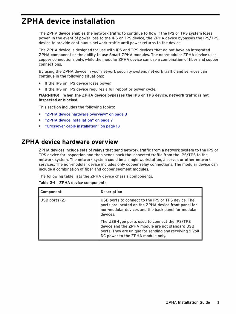
Cabling requirementsThe ZPHA device requires the following cables:
• Nonstandard USB cable to connect to the IPS/TPS device to receive power (included with device).
• Fiber or copper network cables, depending on the segment type. Four cables are required per segment: two for the IPS/TPS device connections and two for network connections (cables not included).
Unpack the ZPHA deviceEach system chassis is securely packaged in a shipping box.
CAUTION: ESD can damage the product if you do not take necessary precautions. Installation and maintenance personnel should be properly grounded using ground straps to eliminate the risk of ESD damage to the equipment. All cards and modules are subject to ESD damage whenever they are removed from the chassis.
Use caution when opening the product boxes.
To unpack the ZPHA system, complete the following steps:
1. Inspect the packing container. If you see any damage or other signs of mishandling, inform both the local freight provider and TippingPoint before unpacking. Your freight provider can provide you with the procedures necessary to file a claim for damages.
2. Carefully open the box.
3. Remove all packing material.
4. Verify the contents in the shipping package. Compare the packing list to your shipment and to your order. Are all items included? If items are missing, contact your TippingPoint sales or field representative.
5. Remove the chassis from the box.
6. Open the accessory kit. It contains the cables, documentation, and management software.
7. Inspect all the equipment inside for damage. If you think any equipment might be damaged, contact your freight provider for how to lodge a damage claim. Also, contact your TippingPoint sales or field representative for instructions.
NOTE: The shipping materials are recyclable. Save for later use or dispose of them appropriately.
2
ZPHA device installationThe ZPHA device enables the network traffic to continue to flow if the IPS or TPS system loses power. In the event of power loss to the IPS or TPS device, the ZPHA device bypasses the IPS/TPS device to provide continuous network traffic until power returns to the device.
The ZPHA device is designed for use with IPS and TPS devices that do not have an integrated ZPHA component or the ability to use Smart ZPHA modules. The non-modular ZPHA device uses copper connections only, while the modular ZPHA device can use a combination of fiber and copper connections.
By using the ZPHA device in your network security system, network traffic and services can continue in the following situations:
• If the IPS or TPS device loses power.
• If the IPS or TPS device requires a full reboot or power cycle.
WARNING! When the ZPHA device bypasses the IPS or TPS device, network traffic is not inspected or blocked.
This section includes the following topics:
• “ZPHA device hardware overview” on page 3
• “ZPHA device installation” on page 7
• “Crossover cable installation” on page 13
ZPHA device hardware overviewZPHA devices include sets of relays that send network traffic from a network system to the IPS or TPS device for inspection and then sends back the inspected traffic from the IPS/TPS to the network system. The network system could be a single workstation, a server, or other network services. The non-modular device includes only copper relay connections. The modular device can include a combination of fiber and copper segment modules.
The following table lists the ZPHA device chassis components.
Table 2-1 ZPHA device components
Component Description
USB ports (2) USB ports to connect to the IPS or TPS device. The ports are located on the ZPHA device front panel for non-modular devices and the back panel for modular devices.
The USB-type ports used to connect the IPS/TPS device and the ZPHA module are not standard USB ports. They are unique for sending and receiving 5 Volt DC power to the ZPHA module only.
ZPHA Installation Guide 3
ZPHA device USB-type portsThe ZPHA device receives power through the nonstandard USB connection to the IPS or TPS device. If the power through the USB cable is interrupted because of IPS/TPS device power supply failure or power loss, the ZPHA device instantly reroutes network traffic, bypassing the IPS/TPS device connections.
The ZPHA device has two USB ports. The ZPHA chassis can be daisy chained by connecting them through their USB-type ports. See “Daisy-chain configuration” on page 12 for more information.
WARNING! Do not use the nonstandard USB power cords to connect a single ZPHA device to multiple IPS or TPS devices. The ZPHA device does not function correctly when connected to multiple power sources.
The USB-type ports are located on the back of the modular ZPHA device and on the front of the non-modular ZPHA device. The modular ZPHA device includes one type A and one type B USB port, while the non-modular ZPHA device includes two type B USB ports.
You can connect the IPS or TPS device to the ZPHA device through the A or B USB-type port, depending on your configuration requirements.
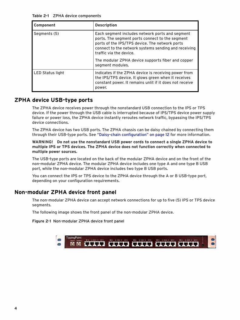
Non-modular ZPHA device front panelThe non-modular ZPHA device can accept network connections for up to five (5) IPS or TPS device segments.
The following image shows the front panel of the non-modular ZPHA device.
Segments (5) Each segment includes network ports and segment ports. The segment ports connect to the segment ports of the IPS/TPS device. The network ports connect to the network systems sending and receiving traffic via the device.
The modular ZPHA device supports fiber and copper segment modules.
LED Status light Indicates if the ZPHA device is receiving power from the IPS/TPS device. It glows green when it receives constant power. It remains unlit if it does not receive power.
Table 2-1 ZPHA device components
Component Description
Figure 2-1 Non-modular ZPHA device front panel
4
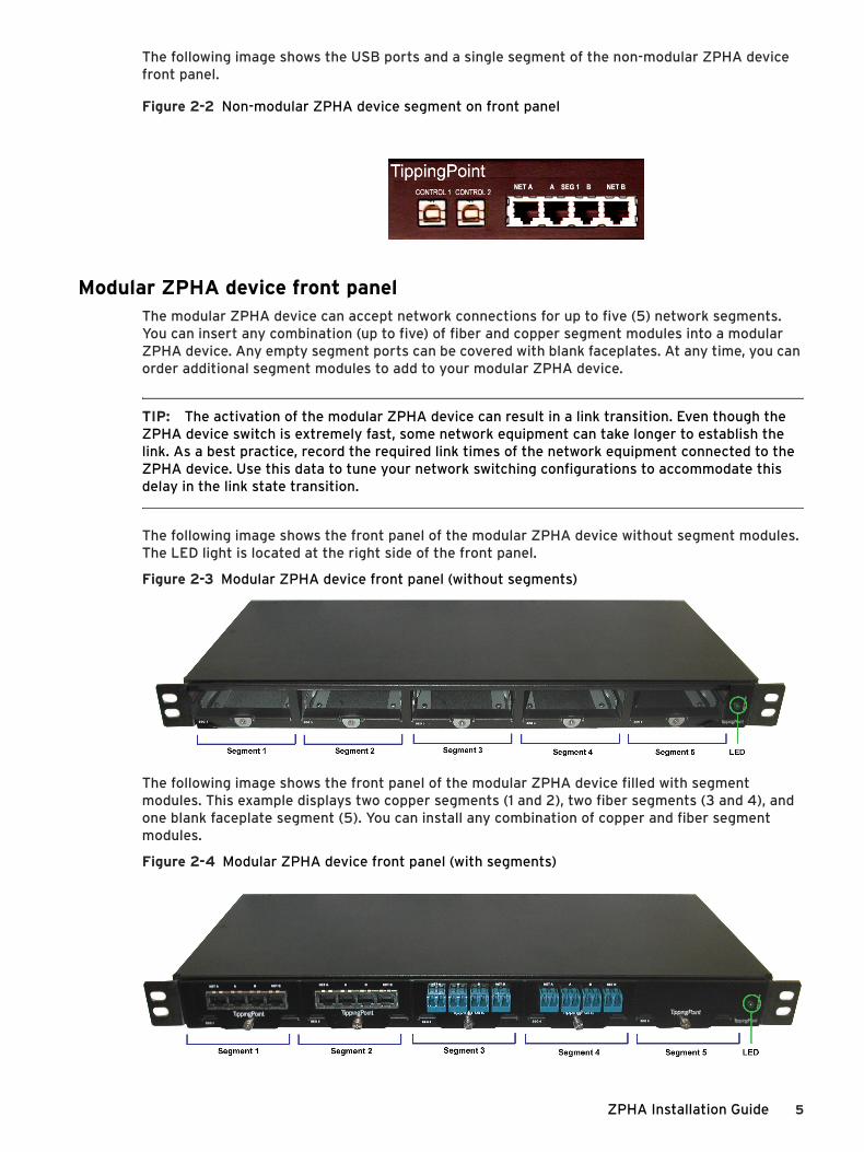
The following image shows the USB ports and a single segment of the non-modular ZPHA device front panel.
Modular ZPHA device front panelThe modular ZPHA device can accept network connections for up to five (5) network segments. You can insert any combination (up to five) of fiber and copper segment modules into a modular ZPHA device. Any empty segment ports can be covered with blank faceplates. At any time, you can order additional segment modules to add to your modular ZPHA device.
TIP: The activation of the modular ZPHA device can result in a link transition. Even though the ZPHA device switch is extremely fast, some network equipment can take longer to establish the link. As a best practice, record the required link times of the network equipment connected to the ZPHA device. Use this data to tune your network switching configurations to accommodate this delay in the link state transition.
The following image shows the front panel of the modular ZPHA device without segment modules. The LED light is located at the right side of the front panel.
Figure 2-3 Modular ZPHA device front panel (without segments)
The following image shows the front panel of the modular ZPHA device filled with segment modules. This example displays two copper segments (1 and 2), two fiber segments (3 and 4), and one blank faceplate segment (5). You can install any combination of copper and fiber segment modules.
Figure 2-4 Modular ZPHA device front panel (with segments)
Figure 2-2 Non-modular ZPHA device segment on front panel
ZPHA Installation Guide 5
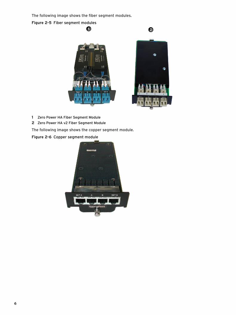
The following image shows the fiber segment modules.
Figure 2-5 Fiber segment modules
1 Zero Power HA Fiber Segment Module
2 Zero Power HA v2 Fiber Segment Module
The following image shows the copper segment module.
Figure 2-6 Copper segment module
6
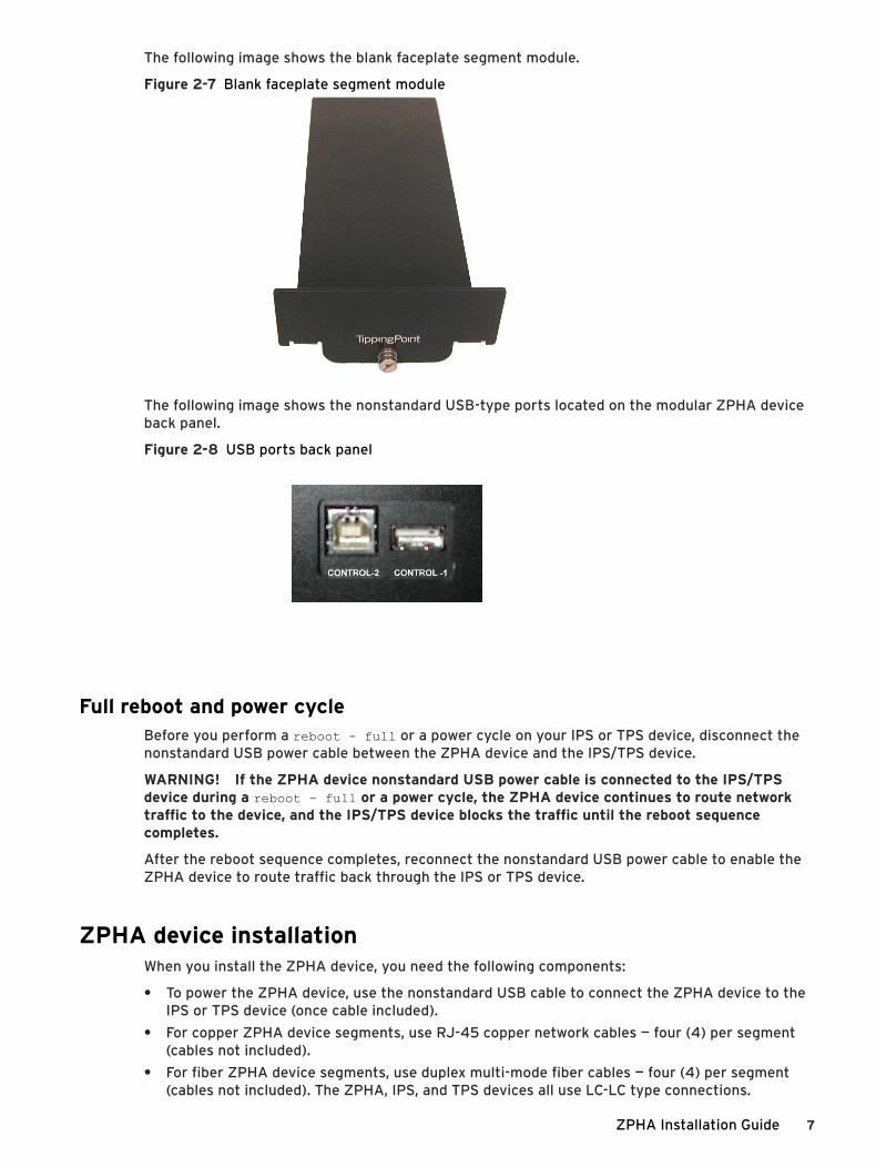
The following image shows the blank faceplate segment module.
Figure 2-7 Blank faceplate segment module
The following image shows the nonstandard USB-type ports located on the modular ZPHA device back panel.
Figure 2-8 USB ports back panel
Full reboot and power cycleBefore you perform a reboot - full or a power cycle on your IPS or TPS device, disconnect the nonstandard USB power cable between the ZPHA device and the IPS/TPS device.
WARNING! If the ZPHA device nonstandard USB power cable is connected to the IPS/TPS device during a reboot - full or a power cycle, the ZPHA device continues to route network traffic to the device, and the IPS/TPS device blocks the traffic until the reboot sequence completes.
After the reboot sequence completes, reconnect the nonstandard USB power cable to enable the ZPHA device to route traffic back through the IPS or TPS device.
ZPHA device installationWhen you install the ZPHA device, you need the following components:
• To power the ZPHA device, use the nonstandard USB cable to connect the ZPHA device to the IPS or TPS device (once cable included).
• For copper ZPHA device segments, use RJ-45 copper network cables — four (4) per segment (cables not included).
• For fiber ZPHA device segments, use duplex multi-mode fiber cables — four (4) per segment (cables not included). The ZPHA, IPS, and TPS devices all use LC-LC type connections.
ZPHA Installation Guide 7
For each segment or module, either fiber or copper, use four cable connections. Two of the connections should be between the ZPHA device and the IPS/TPS device (one for SEG A port, one for SEG B port), and two of the connections should be between the ZPHA device and the network (one for NET A port, one for NET B port).
Keep the following information in mind during ZPHA device installation:
• Do not turn on the IPS/TPS device while installing the ZPHA device.
• Fiber segment modules have a minimum link loss of 1.5db.
• You need a set of four cables for every IPS/TPS device segment that you connect to a ZPHA device segment. The ZPHA device can connect up to five (5) device segments.
Modular ZPHA device installationUse the following procedure to install the modular ZPHA device.
Install the ZPHA device case and modules1. After you unpack the ZPHA device, install the device into the rack. The ZPHA device must be
located close to the IPS/TPS device to connect them.
NOTE: Mount the ZPHA device in a standard 19-or 23-inch rack. The vertical hole spacing on the rack rails must meet standard EIA-310-C requirements, which call for one inch (2.54 cm) spacing.
2. After installing the system case, place a segment module into a segment port. Make sure the segment port is secure. You can place one segment module (fiber or copper) into each segment port. You can install the segment modules in any order.
3. Turn the screw located at the bottom of the segment with your thumb or a Philips screw driver to lock the segment module in the port.
Repeat Steps 2 and 3 as necessary for each segment module. For empty segment modules, install the blank faceplate component.
Connect fiber cables1. Connect the duplex multi-mode fiber cables to route network traffic through the ZPHA device to
the IPS/TPS device:
• Connect a cable from port A of the IPS/TPS device to port A of the ZPHA device segment.
• Connect a cable from port B of the IPS/TPS device to port B of the ZPHA device segment.
2. Connect the duplex multi-mode fiber cables to route traffic through the ZPHA device ports to your network.
• Connect the cable for incoming traffic to port NET A on the ZPHA device.
• Connect the cable for outgoing traffic to port NET B on the ZPHA device.
See the following diagram.
8
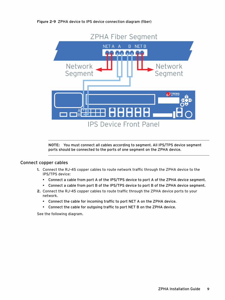
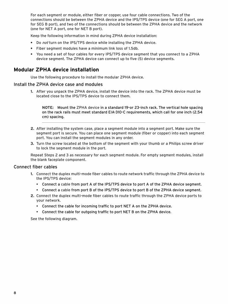
Figure 2-9 ZPHA device to IPS device connection diagram (fiber)
NOTE: You must connect all cables according to segment. All IPS/TPS device segment ports should be connected to the ports of one segment on the ZPHA device.
Connect copper cables1. Connect the RJ-45 copper cables to route network traffic through the ZPHA device to the
IPS/TPS device:
• Connect a cable from port A of the IPS/TPS device to port A of the ZPHA device segment.
• Connect a cable from port B of the IPS/TPS device to port B of the ZPHA device segment.
2. Connect the RJ-45 copper cables to route traffic through the ZPHA device ports to your network.
• Connect the cable for incoming traffic to port NET A on the ZPHA device.
• Connect the cable for outgoing traffic to port NET B on the ZPHA device.
See the following diagram.
ZPHA Installation Guide 9
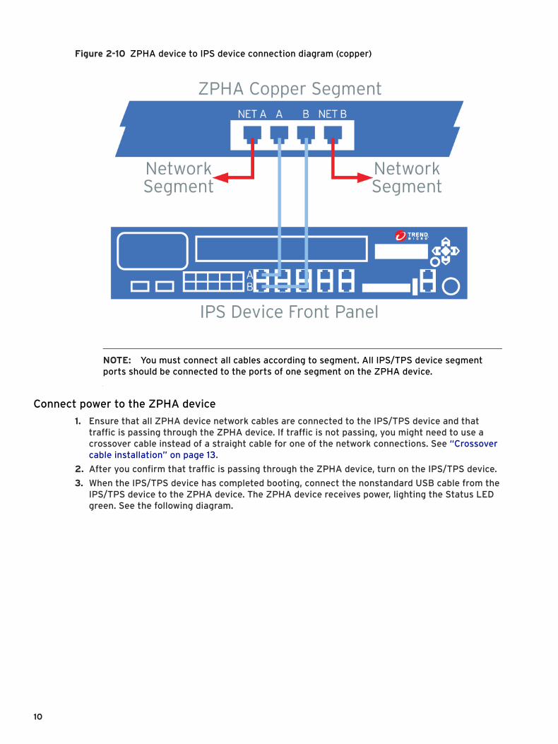
Figure 2-10 ZPHA device to IPS device connection diagram (copper)
NOTE: You must connect all cables according to segment. All IPS/TPS device segment ports should be connected to the ports of one segment on the ZPHA device.
Connect power to the ZPHA device1. Ensure that all ZPHA device network cables are connected to the IPS/TPS device and that
traffic is passing through the ZPHA device. If traffic is not passing, you might need to use a crossover cable instead of a straight cable for one of the network connections. See “Crossover cable installation” on page 13.
2. After you confirm that traffic is passing through the ZPHA device, turn on the IPS/TPS device.
3. When the IPS/TPS device has completed booting, connect the nonstandard USB cable from the IPS/TPS device to the ZPHA device. The ZPHA device receives power, lighting the Status LED green. See the following diagram.
10
WARNING! Do not connect the USB cable until the IPS/TPS device is completely turned on. If you connect the USB cable before you turn on the device, network traffic halts until the IPS/TPS device is fully operational.
Figure 2-11 USB-type connection
Non-modular ZPHA device installation1. After unpacking the ZPHA device, install the device into the rack. The ZPHA device must be
located close to the IPS/TPS device to be networked to it.
NOTE: Mount the ZPHA device in a standard 19- or 23-inch rack. The vertical hole spacing on the rack rails must meet standard EIA-310-C requirements, which call for a one inch (2.54 cm) spacing.
2. Connect the RJ-45 copper cables to route network traffic through the ZPHA device to the IPS/TPS device:
• Connect a cable from port A of the IPS/TPS device to port A of the ZPHA device segment.
• Connect a cable from port B of the IPS/TPS device to port B of the ZPHA device segment.
3. Connect the RJ-45 copper cables to route traffic through the ZPHA device ports to your network:
• Connect the cable for incoming traffic to port NET A on the ZPHA device.
• Connect the cable for outgoing traffic to port NET B on the ZPHA device.
See the following diagram.
ZPHA Installation Guide 11
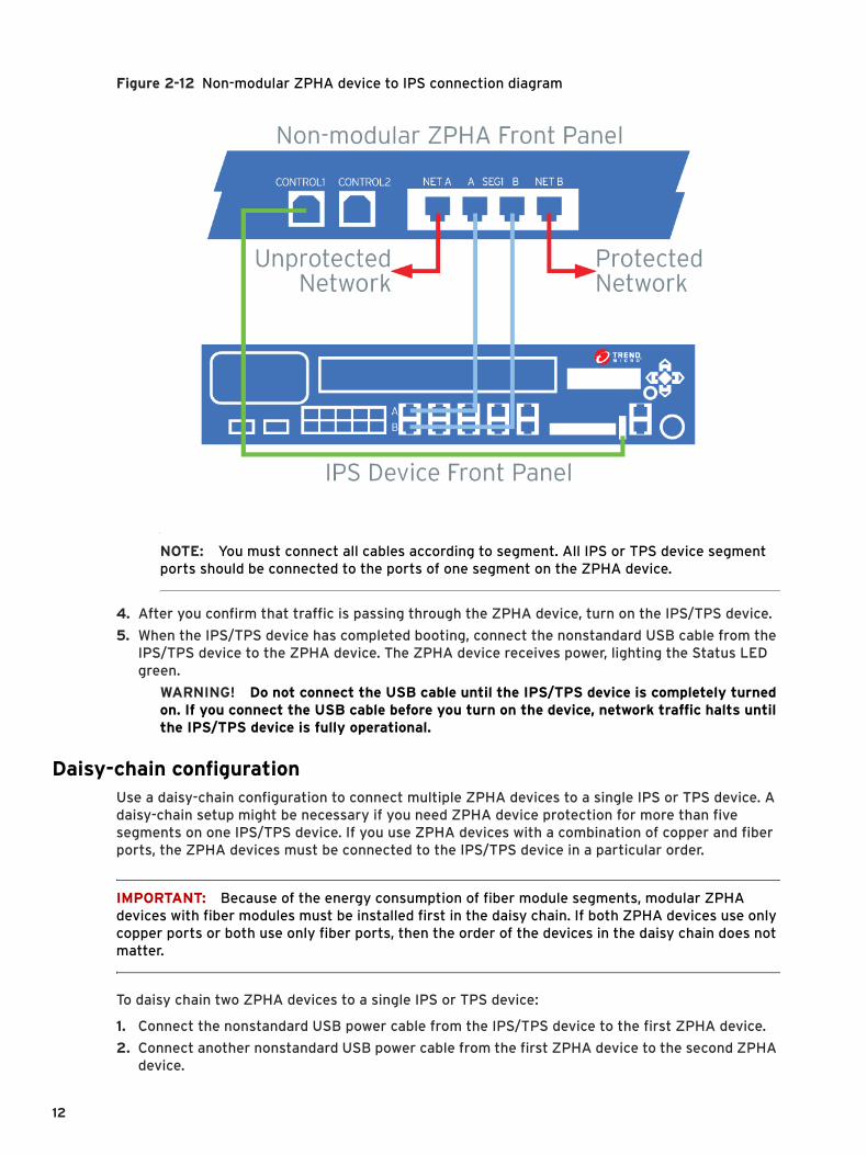
Figure 2-12 Non-modular ZPHA device to IPS connection diagram
NOTE: You must connect all cables according to segment. All IPS or TPS device segment ports should be connected to the ports of one segment on the ZPHA device.
4. After you confirm that traffic is passing through the ZPHA device, turn on the IPS/TPS device.
5. When the IPS/TPS device has completed booting, connect the nonstandard USB cable from the IPS/TPS device to the ZPHA device. The ZPHA device receives power, lighting the Status LED green.
WARNING! Do not connect the USB cable until the IPS/TPS device is completely turned on. If you connect the USB cable before you turn on the device, network traffic halts until the IPS/TPS device is fully operational.
Daisy-chain configurationUse a daisy-chain configuration to connect multiple ZPHA devices to a single IPS or TPS device. A daisy-chain setup might be necessary if you need ZPHA device protection for more than five segments on one IPS/TPS device. If you use ZPHA devices with a combination of copper and fiber ports, the ZPHA devices must be connected to the IPS/TPS device in a particular order.
IMPORTANT: Because of the energy consumption of fiber module segments, modular ZPHA devices with fiber modules must be installed first in the daisy chain. If both ZPHA devices use only copper ports or both use only fiber ports, then the order of the devices in the daisy chain does not matter.
To daisy chain two ZPHA devices to a single IPS or TPS device:
1. Connect the nonstandard USB power cable from the IPS/TPS device to the first ZPHA device.
2. Connect another nonstandard USB power cable from the first ZPHA device to the second ZPHA device.
12
WARNING! Do not connect both ZPHA devices directly to the IPS/TPS device using the nonstandard USB power cable.
Crossover cable installationDepending on your network environment, you might need to use a crossover cable to connect the ZPHA device to your network configuration.
The TippingPoint IPS, TPS, and ZPHA device ports are all enabled with automatic medium-dependent interface crossover (auto-MDIX). Auto-MDIX enables the devices to automatically detect and activate the required cable connection type. However, if the network devices connected to the ZPHA device are not auto-MDIX-enabled, you might still need to use a crossover cable in your configuration.
The following figures display different installations of the ZPHA device in different network environments.
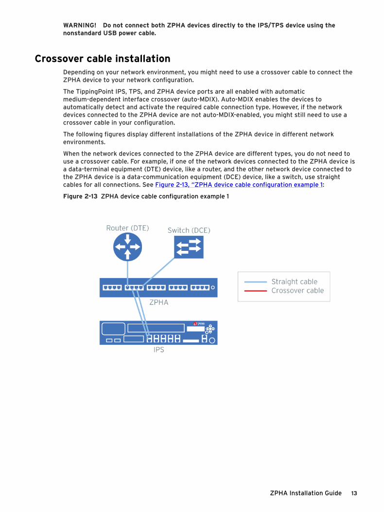
When the network devices connected to the ZPHA device are different types, you do not need to use a crossover cable. For example, if one of the network devices connected to the ZPHA device is a data-terminal equipment (DTE) device, like a router, and the other network device connected to the ZPHA device is a data-communication equipment (DCE) device, like a switch, use straight cables for all connections. See Figure 2-13, “ZPHA device cable configuration example 1:
Figure 2-13 ZPHA device cable configuration example 1
ZPHA Installation Guide 13
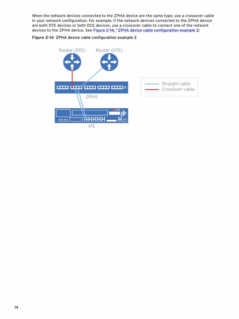
When the network devices connected to the ZPHA device are the same type, use a crossover cable in your network configuration. For example, if the network devices connected to the ZPHA device are both DTE devices or both DCE devices, use a crossover cable to connect one of the network devices to the ZPHA device. See Figure 2-14, “ZPHA device cable configuration example 2:
Figure 2-14 ZPHA device cable configuration example 2
14