z/OS Communications Server use of OSA (Open … Communications Server use of OSA (Open System...
98
z/OS Communications Server use of OSA (Open System Adapter) Ethernet and Token Ring Linda Harrison [email protected] IBM Advanced Technical Skills
Transcript of z/OS Communications Server use of OSA (Open … Communications Server use of OSA (Open System...
z/OS Communications Server
use of OSA (Open System Adapter)
Ethernet and Token Ring
Linda Harrison
IBM Advanced Technical Skills

09/27/2011 www.ibm.com/support/techdocs Document PRS3169
© IBM Corporation, 2011 --- Last Updated 09/27/2011
Page 2
Trademarks and Limitations
The following are Registered Trademarks of the International Business Machines Corporation in the United States and/or
other countries.
IBM
z/OS
The following are trademarks or registered trademarks of other companies.
•All other products may be trademarks or registered trademarks of their respective companies.
Refer to www.ibm.com/legal/us for further legal information.
Microsoft is a registered trademark of Microsoft Corporation in the United States and other countries.
09/27/2011 www.ibm.com/support/techdocs Document PRS3169
© IBM Corporation, 2011 --- Last Updated 09/27/2011
Page 3
Agenda
• OSA Overview
• OSA QDIO TCP/IP Outbound Queues
• OSA QDIO TCP/IP Gratuitous ARP Fail-Over Support
• TCP/IP IPCONFIG Multipath Support
• OSA Definition
• OSA TCP/IP Device/Link/Interface Parameter Descriptions
• OSA Read Storage Usage
• OSA VLAN Support
• OSA Optimized Latency Mode (OLM)
• OSA Interface Isolation
• OSA Error Support
• OSA TCP/IP Considerations
• QDIO Accelerator
• OSA-Express Network Traffic Analyzer (OSAENTA)
• Synchronization of OSA Diagnostic Data (QDIOSYNC)
• OSA Segmentation Offload
• Commands
• More Information
09/27/2011 www.ibm.com/support/techdocs Document PRS3169
© IBM Corporation, 2011 --- Last Updated 09/27/2011
Page 4
OSA Overview
OSA-E
Customer's
Guide and
Reference
SA22-7935
Redbook
OSA-E
Implementation
Guide
SG24-5948
OSA-E
Integrated
Console
Controller
User’s Guide
SA22-7990
09/27/2011 www.ibm.com/support/techdocs Document PRS3169
© IBM Corporation, 2011 --- Last Updated 09/27/2011
Page 5
LAN Attachment
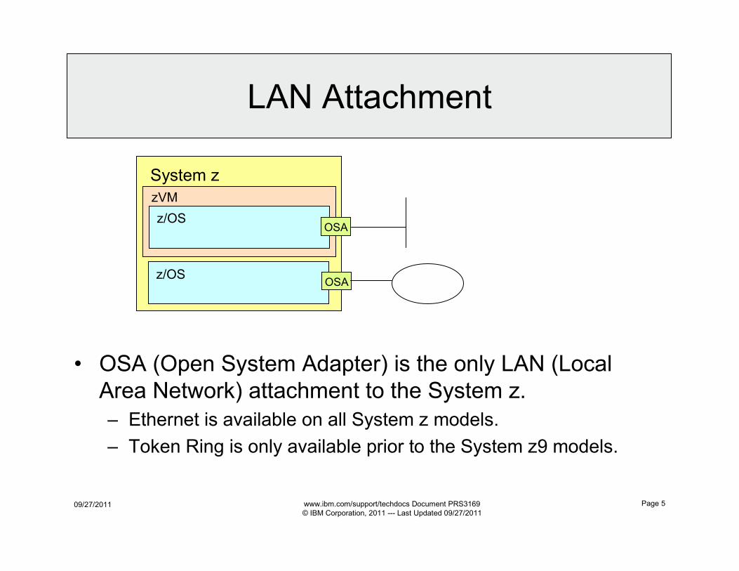
• OSA (Open System Adapter) is the only LAN (Local
Area Network) attachment to the System z.
– Ethernet is available on all System z models.
– Token Ring is only available prior to the System z9 models.
System z
zVM
z/OS
z/OS
OSA
OSA
09/27/2011 www.ibm.com/support/techdocs Document PRS3169
© IBM Corporation, 2011 --- Last Updated 09/27/2011
Page 6
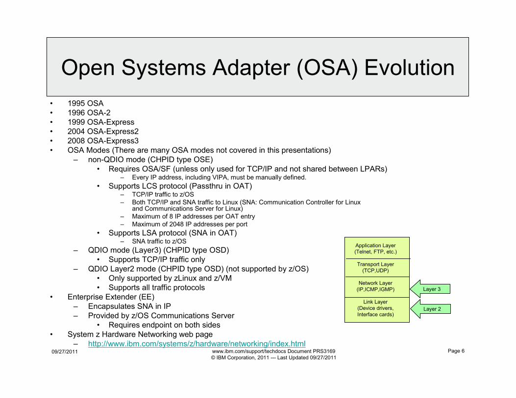
Open Systems Adapter (OSA) Evolution
• 1995 OSA
• 1996 OSA-2
• 1999 OSA-Express
• 2004 OSA-Express2
• 2008 OSA-Express3
• OSA Modes (There are many OSA modes not covered in this presentations)
– non-QDIO mode (CHPID type OSE)
• Requires OSA/SF (unless only used for TCP/IP and not shared between LPARs)– Every IP address, including VIPA, must be manually defined.
• Supports LCS protocol (Passthru in OAT)– TCP/IP traffic to z/OS
– Both TCP/IP and SNA traffic to Linux (SNA: Communication Controller for Linux and Communications Server for Linux)
– Maximum of 8 IP addresses per OAT entry
– Maximum of 2048 IP addresses per port
• Supports LSA protocol (SNA in OAT)– SNA traffic to z/OS
– QDIO mode (Layer3) (CHPID type OSD)
• Supports TCP/IP traffic only
– QDIO Layer2 mode (CHPID type OSD) (not supported by z/OS)
• Only supported by zLinux and z/VM
• Supports all traffic protocols
• Enterprise Extender (EE)
– Encapsulates SNA in IP
– Provided by z/OS Communications Server
• Requires endpoint on both sides
• System z Hardware Networking web page
– http://www.ibm.com/systems/z/hardware/networking/index.html
Application Layer
(Telnet, FTP, etc.)
Transport Layer
(TCP,UDP)
Network Layer
(IP,ICMP,IGMP)
Link Layer
(Device drivers,
Interface cards)Layer 2
Layer 3
09/27/2011 www.ibm.com/support/techdocs Document PRS3169
© IBM Corporation, 2011 --- Last Updated 09/27/2011
Page 7
OSA CHPID vs. OSA Port
• Prior to OSA-Express3:
– OSA cards have one or two ports per card
– All OSA cards have one port per CHPID
• OSA-Express3:
– OSA cards have two or four ports per card
– All OSA cards have two ports per CHPID
• Each OSA CHPID is configurable in only one OSA mode.
• Each OSA CHPID is configured completely independently from the other OSA CHPID on the same OSA card.
• When an OSA-Express3 CHPID is configured in a particular OSA mode then both ports on that CHPID are configured in that OSA mode.
– If an OSA-E3 CHPID is configured in OSN mode then the CHPID is dedicated to OSN usage and both ports on that CHPID are disabled.
• Not all OSA modes are supported on all OSA cards.
• See the OSA documentation for supported OSA cards and corresponding OSA modes. Some of the OSA features are detailed on a later foil.
• Throughout this presentation where OSA is mentioned it implies OSA port.
09/27/2011 www.ibm.com/support/techdocs Document PRS3169
© IBM Corporation, 2011 --- Last Updated 09/27/2011
Page 8
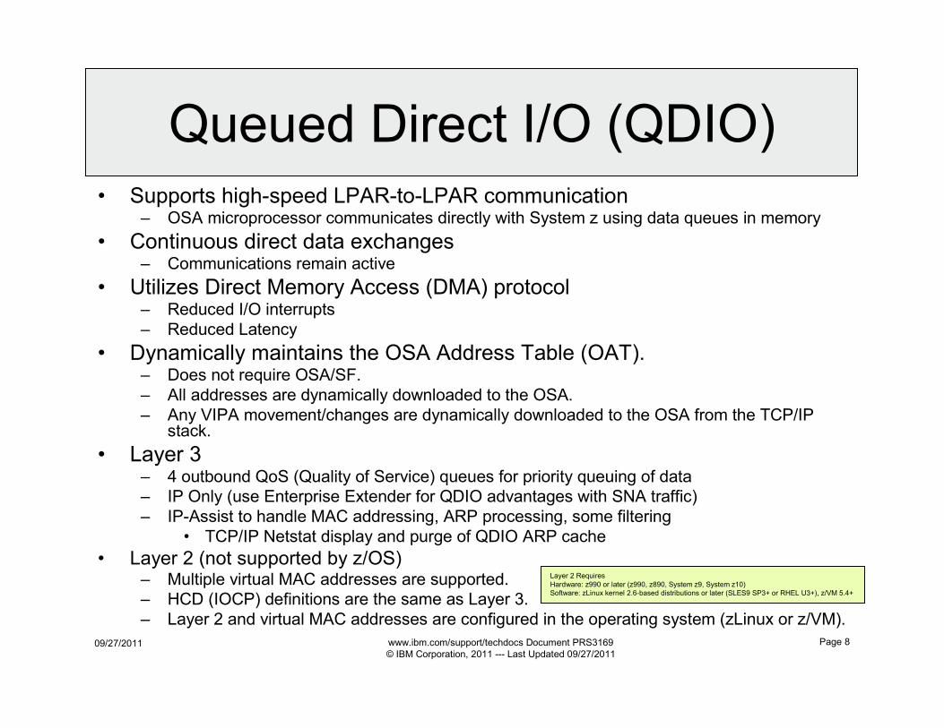
Queued Direct I/O (QDIO)• Supports high-speed LPAR-to-LPAR communication
– OSA microprocessor communicates directly with System z using data queues in memory
• Continuous direct data exchanges– Communications remain active
• Utilizes Direct Memory Access (DMA) protocol– Reduced I/O interrupts
– Reduced Latency
• Dynamically maintains the OSA Address Table (OAT).– Does not require OSA/SF.
– All addresses are dynamically downloaded to the OSA.
– Any VIPA movement/changes are dynamically downloaded to the OSA from the TCP/IP stack.
• Layer 3– 4 outbound QoS (Quality of Service) queues for priority queuing of data
– IP Only (use Enterprise Extender for QDIO advantages with SNA traffic)
– IP-Assist to handle MAC addressing, ARP processing, some filtering
• TCP/IP Netstat display and purge of QDIO ARP cache
• Layer 2 (not supported by z/OS)– Multiple virtual MAC addresses are supported.
– HCD (IOCP) definitions are the same as Layer 3.
– Layer 2 and virtual MAC addresses are configured in the operating system (zLinux or z/VM).
Layer 2 Requires
Hardware: z990 or later (z990, z890, System z9, System z10)
Software: zLinux kernel 2.6-based distributions or later (SLES9 SP3+ or RHEL U3+), z/VM 5.4+
09/27/2011 www.ibm.com/support/techdocs Document PRS3169
© IBM Corporation, 2011 --- Last Updated 09/27/2011
Page 9
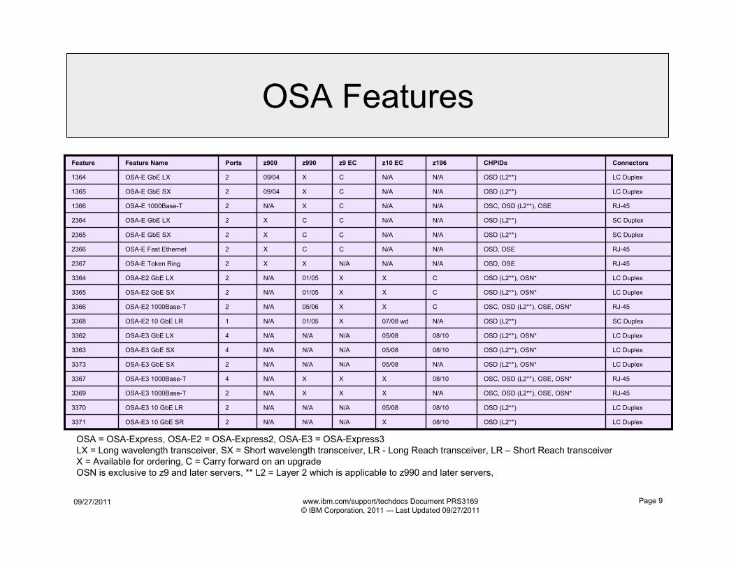
OSA Features
OSA = OSA-Express, OSA-E2 = OSA-Express2, OSA-E3 = OSA-Express3
LX = Long wavelength transceiver, SX = Short wavelength transceiver, LR - Long Reach transceiver, LR – Short Reach transceiver
X = Available for ordering, C = Carry forward on an upgrade
OSN is exclusive to z9 and later servers, ** L2 = Layer 2 which is applicable to z990 and later servers,
LC DuplexOSD (L2**), OSN*N/A05/08N/AN/AN/A2OSA-E3 GbE SX3373
RJ-45OSC, OSD (L2**), OSE, OSN*08/10XXXN/A4OSA-E3 1000Base-T3367
LC DuplexOSD (L2**), OSN*08/1005/08N/AN/AN/A4OSA-E3 GbE SX3363
LC DuplexOSD (L2**)N/AN/ACX09/042OSA-E GbE LX1364
LC DuplexOSD (L2**)N/AN/ACX09/042OSA-E GbE SX1365
RJ-45OSC, OSD (L2**), OSEN/AN/ACXN/A2OSA-E 1000Base-T1366
X
05/08
X
05/08
07/08 wd
X
X
X
N/A
N/A
N/A
N/A
z10 EC
LC DuplexOSD (L2**)08/10N/AN/AN/A2OSA-E3 10 GbE LR3370
RJ-45OSC, OSD (L2**), OSE, OSN*N/AXXN/A2OSA-E3 1000Base-T3369
LC DuplexOSD (L2**), OSN*08/10N/AN/AN/A4OSA-E3 GbE LX3362
LC DuplexOSD (L2**)08/10N/AN/AN/A2OSA-E3 10 GbE SR3371
SC DuplexOSD (L2**)N/AX01/05N/A1OSA-E2 10 GbE LR3368
LC DuplexOSD (L2**), OSN*CX01/05N/A2OSA-E2 GbE LX3364
LC DuplexOSD (L2**), OSN*CX01/05N/A2OSA-E2 GbE SX3365
RJ-45OSC, OSD (L2**), OSE, OSN*CX05/06N/A2OSA-E2 1000Base-T3366
RJ-45OSD, OSEN/AN/AXX2OSA-E Token Ring2367
RJ-45OSD, OSEN/ACCX2OSA-E Fast Ethernet2366
SC DuplexOSD (L2**)N/ACCX2OSA-E GbE SX2365
SC DuplexOSD (L2**)N/ACCX2OSA-E GbE LX2364
ConnectorsCHPIDsz196z9 ECz990z900PortsFeature NameFeature
09/27/2011 www.ibm.com/support/techdocs Document PRS3169
© IBM Corporation, 2011 --- Last Updated 09/27/2011
Page 10
OSA QDIO TCP/IP
Outbound Queues
09/27/2011 www.ibm.com/support/techdocs Document PRS3169
© IBM Corporation, 2011 --- Last Updated 09/27/2011
Page 11
Policy Agent Quality of Service (QoS)
Configuration - Priority Routing Queues
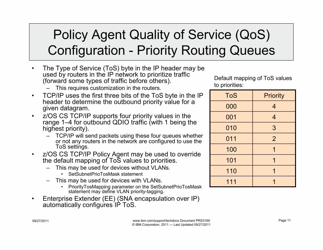
• The Type of Service (ToS) byte in the IP header may be used by routers in the IP network to prioritize traffic (forward some types of traffic before others).– This requires customization in the routers.
• TCP/IP uses the first three bits of the ToS byte in the IP header to determine the outbound priority value for a given datagram.
• z/OS CS TCP/IP supports four priority values in the range 1–4 for outbound QDIO traffic (with 1 being the highest priority).– TCP/IP will send packets using these four queues whether
or not any routers in the network are configured to use the ToS settings.
• z/OS CS TCP/IP Policy Agent may be used to override the default mapping of ToS values to priorities.– This may be used for devices without VLANs.
• SetSubnetPrioTosMask statement
– This may be used for devices with VLANs.• PriorityTosMapping parameter on the SetSubnetPrioTosMask
statement may define VLAN priority-tagging.
• Enterprise Extender (EE) (SNA encapsulation over IP) automatically configures IP ToS.
1111
1110
1101
1100
2011
3010
4001
4000
PriorityToS
Default mapping of ToS values
to priorities:
09/27/2011 www.ibm.com/support/techdocs Document PRS3169
© IBM Corporation, 2011 --- Last Updated 09/27/2011
Page 12
Policy Agent Syntax to Map TOS to Priority
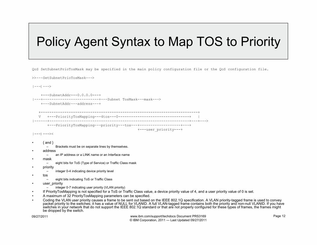
QoS SetSubnetPrioTosMask may be specified in the main policy configuration file or the QoS configuration file.
>>---SetSubnetPrioTosMask--->
|---{--->
+---SubnetAddr---0.0.0.0---+ |---+--------------------------+---Subnet TosMask---mask--->
+---SubnetAddr---address---+
+-------------------------------------------------------------------------+
V +---PriorityTosMapping---4tos---0---------------------------------+ ||------+-----------------------------------------------------------------+---+--->
+---PriorityTosMapping---priority---tos---+-------------------+---++---user_priority---+
|---}---><
• { and }– Brackets must be on separate lines by themselves.
• address– an IP address or a LINK name or an Interface name
• mask– eight bits for ToS (Type of Service) or Traffic Class mask
• priority– integer 0-4 indicating device priority level
• tos– eight bits indicating ToS or Traffic Class
• user_priority– integer 0-7 indicating user priority (VLAN priority)
• If PriorityTosMapping is not specified for a ToS or Traffic Class value, a device priority value of 4, and a user priority value of 0 is set.
• A maximum of 32 PriorityTosMapping parameters can be specified.
• Coding the VLAN user priority causes a frame to be sent out based on the IEEE 802.1Q specification. A VLAN priority-tagged frame is used to convey packet priority to the switches; it has a value of NULL for VLANID. A full VLAN-tagged frame contains both the priority and non-null VLANID. If you have switches in your network that do not support the IEEE 802.1Q standard or that are not properly configured for these types of frames, the frames might be dropped by the switch.
09/27/2011 www.ibm.com/support/techdocs Document PRS3169
© IBM Corporation, 2011 --- Last Updated 09/27/2011
Page 13
WLM IO Priority Determines QDIO Queue
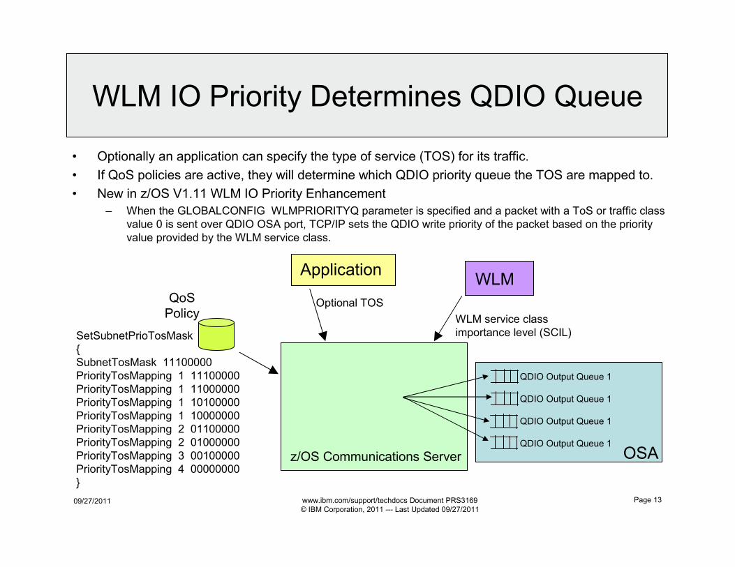
• Optionally an application can specify the type of service (TOS) for its traffic.
• If QoS policies are active, they will determine which QDIO priority queue the TOS are mapped to.
• New in z/OS V1.11 WLM IO Priority Enhancement
– When the GLOBALCONFIG WLMPRIORITYQ parameter is specified and a packet with a ToS or traffic class
value 0 is sent over QDIO OSA port, TCP/IP sets the QDIO write priority of the packet based on the priority
value provided by the WLM service class.
SetSubnetPrioTosMask
{
SubnetTosMask 11100000
PriorityTosMapping 1 11100000
PriorityTosMapping 1 11000000
PriorityTosMapping 1 10100000
PriorityTosMapping 1 10000000
PriorityTosMapping 2 01100000
PriorityTosMapping 2 01000000
PriorityTosMapping 3 00100000
PriorityTosMapping 4 00000000
}
QoS
Policy
z/OS Communications Server
Application
Optional TOS
WLM
WLM service class
importance level (SCIL)
QDIO Output Queue 1
QDIO Output Queue 1
QDIO Output Queue 1
QDIO Output Queue 1
OSA
09/27/2011 www.ibm.com/support/techdocs Document PRS3169
© IBM Corporation, 2011 --- Last Updated 09/27/2011
Page 14
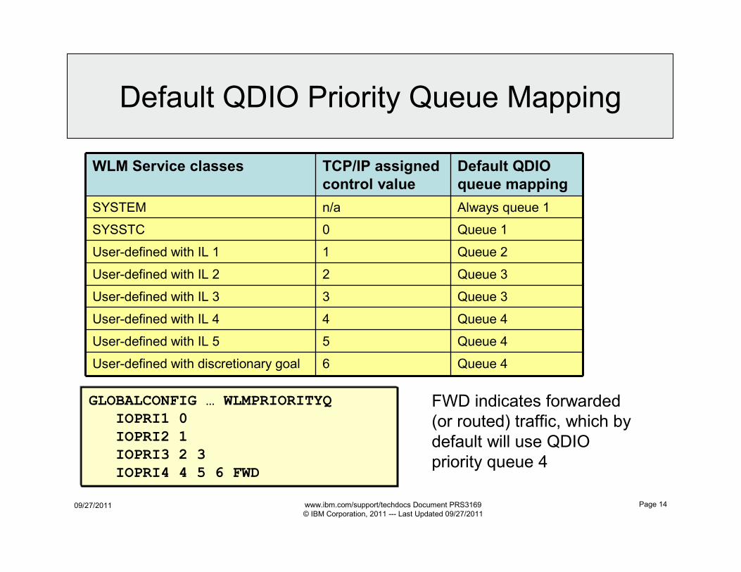
WLM Service classes TCP/IP assigned
control value
Default QDIO
queue mapping
SYSTEM n/a Always queue 1
SYSSTC 0 Queue 1
User-defined with IL 1 1 Queue 2
User-defined with IL 2 2 Queue 3
User-defined with IL 3 3 Queue 3
User-defined with IL 4 4 Queue 4
User-defined with IL 5 5 Queue 4
User-defined with discretionary goal 6 Queue 4
GLOBALCONFIG … WLMPRIORITYQ
IOPRI1 0
IOPRI2 1
IOPRI3 2 3
IOPRI4 4 5 6 FWD
FWD indicates forwarded
(or routed) traffic, which by
default will use QDIO
priority queue 4
Default QDIO Priority Queue Mapping
09/27/2011 www.ibm.com/support/techdocs Document PRS3169
© IBM Corporation, 2011 --- Last Updated 09/27/2011
Page 15
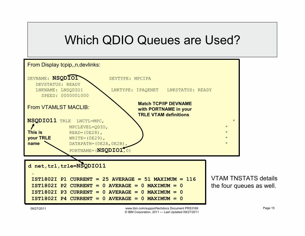
From Display tcpip,,n,devlinks:
DEVNAME: NSQDIO1 DEVTYPE: MPCIPA
DEVSTATUS: READY
LNKNAME: LNSQDIO1 LNKTYPE: IPAQENET LNKSTATUS: READY
SPEED: 0000001000
From VTAMLST MACLIB:
NSQDIO11 TRLE LNCTL=MPC, *
MPCLEVEL=QDIO, *
READ=(0E28), *
WRITE=(0E29), *
DATAPATH=(0E2A,0E2B), *
PORTNAME=(NSQDIO1,0)
This is
your TRLE
name
Match TCP/IP DEVNAME
with PORTNAME in your
TRLE VTAM definitions
d net,trl,trle=NSQDIO11
.
IST1802I P1 CURRENT = 25 AVERAGE = 51 MAXIMUM = 116
IST1802I P2 CURRENT = 0 AVERAGE = 0 MAXIMUM = 0
IST1802I P3 CURRENT = 0 AVERAGE = 0 MAXIMUM = 0
IST1802I P4 CURRENT = 0 AVERAGE = 0 MAXIMUM = 0
Which QDIO Queues are Used?
VTAM TNSTATS details
the four queues as well.
09/27/2011 www.ibm.com/support/techdocs Document PRS3169
© IBM Corporation, 2011 --- Last Updated 09/27/2011
Page 16
OSA QDIO TCP/IP Gratuitous
ARP Fail-Over Support
09/27/2011 www.ibm.com/support/techdocs Document PRS3169
© IBM Corporation, 2011 --- Last Updated 09/27/2011
Page 17
Original OSA with Inbound Connections
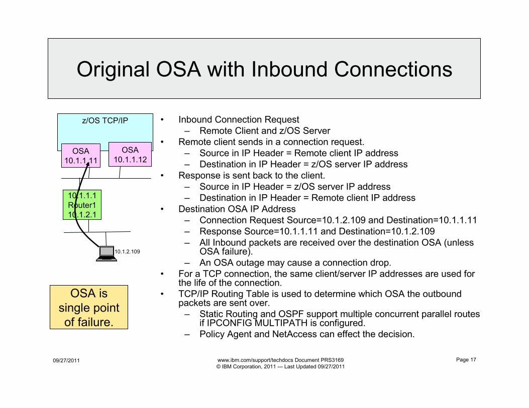
• Inbound Connection Request
– Remote Client and z/OS Server
• Remote client sends in a connection request.
– Source in IP Header = Remote client IP address
– Destination in IP Header = z/OS server IP address
• Response is sent back to the client.
– Source in IP Header = z/OS server IP address
– Destination in IP Header = Remote client IP address
• Destination OSA IP Address
– Connection Request Source=10.1.2.109 and Destination=10.1.1.11
– Response Source=10.1.1.11 and Destination=10.1.2.109
– All Inbound packets are received over the destination OSA (unless OSA failure).
– An OSA outage may cause a connection drop.
• For a TCP connection, the same client/server IP addresses are used for the life of the connection.
• TCP/IP Routing Table is used to determine which OSA the outboundpackets are sent over.
– Static Routing and OSPF support multiple concurrent parallel routes if IPCONFIG MULTIPATH is configured.
– Policy Agent and NetAccess can effect the decision.
10.1.2.109
z/OS TCP/IP
OSA
10.1.1.11
OSA
10.1.1.12
10.1.1.1
Router1
10.1.2.1
OSA is
single point
of failure.
09/27/2011 www.ibm.com/support/techdocs Document PRS3169
© IBM Corporation, 2011 --- Last Updated 09/27/2011
Page 18
OSA QDIO Gratuitous ARP Fail-over
z/OS TCP/IP
OSA
10.1.1.11
OSA
10.1.1.12
10.1.1.2Router210.1.2.2
10.1.1.1Router110.1.2.1
z/OS TCP/IP
OSA
10.1.1.11
OSA10.1.1.1110.1.1.12
10.1.1.2Router210.1.2.2
10.1.1.1Router110.1.2.1
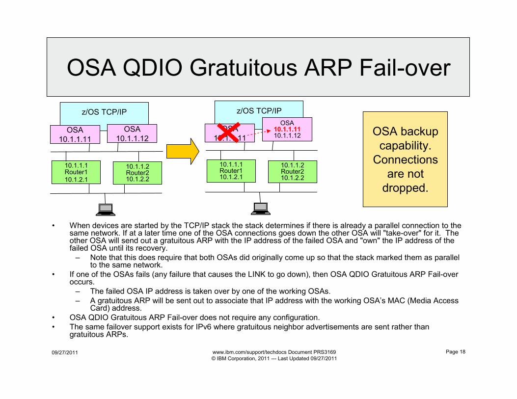
• When devices are started by the TCP/IP stack the stack determines if there is already a parallel connection to the same network. If at a later time one of the OSA connections goes down the other OSA will "take-over" for it. The other OSA will send out a gratuitous ARP with the IP address of the failed OSA and "own" the IP address of the failed OSA until its recovery.
– Note that this does require that both OSAs did originally come up so that the stack marked them as parallel to the same network.
• If one of the OSAs fails (any failure that causes the LINK to go down), then OSA QDIO Gratuitous ARP Fail-over occurs.
– The failed OSA IP address is taken over by one of the working OSAs.
– A gratuitous ARP will be sent out to associate that IP address with the working OSA’s MAC (Media Access Card) address.
• OSA QDIO Gratuitous ARP Fail-over does not require any configuration.
• The same failover support exists for IPv6 where gratuitous neighbor advertisements are sent rather than gratuitous ARPs.
OSA backup
capability.
Connections
are not
dropped.
09/27/2011 www.ibm.com/support/techdocs Document PRS3169
© IBM Corporation, 2011 --- Last Updated 09/27/2011
Page 19
ARP Fail-over with VIPA and Static
Routingz/OS TCP/IP
VIPA 10.1.1.30
VIPA 10.1.1.30OSA
10.1.1.11OSA
10.1.1.12
10.1.1.2Router210.1.2.2
10.1.1.1Router110.1.2.1
z/OS TCP/IP
VIPA 10.1.1.30
VIPA 10.1.1.30
OSA
10.1.1.11
VIPA 10.1.1.30
OSA
10.1.1.11
10.1.1.12
10.1.1.2Router210.1.2.2
10.1.1.1Router110.1.2.1
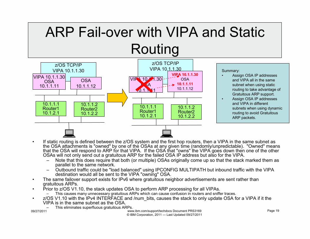
• If static routing is defined between the z/OS system and the first hop routers, then a VIPA in the same subnet as the OSA attachments is "owned" by one of the OSAs at any given time (randomly/unpredictable). "Owned" means that the OSA will respond to ARP for that VIPA. If the OSA that "owns" the VIPA goes down then one of the other OSAs will not only send out a gratuitous ARP for the failed OSA IP address but also for the VIPA.– Note that this does require that both (or multiple) OSAs originally come up so that the stack marked them as
parallel to the same network.– Outbound traffic could be "load balanced" using IPCONFIG MULTIPATH but inbound traffic with the VIPA
destination would all be sent to the VIPA "owning" OSA.• The same failover support exists for IPv6 where gratuitous neighbor advertisements are sent rather than
gratuitous ARPs.• Prior to z/OS V1.10, the stack updates OSA to perform ARP processing for all VIPAs.
– This causes many unnecessary gratuitous ARPs which can cause confusion in routers and sniffer traces.
• z/OS V1.10 with the IPv4 INTERFACE and /num_bits, causes the stack to only update OSA for a VIPA if it the VIPA is in the same subnet as the OSA.– This eliminates superfluous gratuitous ARPs.
Summary:
• Assign OSA IP addresses
and VIPA all in the same
subnet when using static
routing to take advantage of
Gratuitous ARP support.
• Assign OSA IP addresses
and VIPA in different
subnets when using dynamic
routing to avoid Gratuitous
ARP packets.
09/27/2011 www.ibm.com/support/techdocs Document PRS3169
© IBM Corporation, 2011 --- Last Updated 09/27/2011
Page 20
TCP/IP IPCONFIG
Multipath Support

09/27/2011 www.ibm.com/support/techdocs Document PRS3169
© IBM Corporation, 2011 --- Last Updated 09/27/2011
Page 21
IPCONFIG MULTIPATH
z/OS TCP/IP
OSA
10.1.1.11
OSA
10.1.1.12
10.1.1.2
Router2
10.1.2.2
10.1.1.1
Router1
10.1.2.1
BEGINROUTES
ROUTE 10.1.1.0/24 = OSALNK11 MTU 1492ROUTE 10.1.1.0/24 = OSALNK12 MTU 1492
ROUTE DEFAULT 10.1.1.1 OSALNK11 MTU 1492ROUTE DEFAULT 10.1.1.2 OSALNK11 MTU 1492
ROUTE DEFAULT 10.1.1.1 OSALNK12 MTU 1492ROUTE DEFAULT 10.1.1.2 OSALNK12 MTU 1492
ENDROUTES
• IPCONFIG MULTIPATH "load balances" outbound packets
– Static Routing and OMPROUTE OSPF support IPCONFIG MULTIPATH
– Default Multipath routing is per connection as opposed to per packet
• Failed first hop router
– Static Routing Dead Gateway Detection
• TCP connection will eventually timeout (3 to 10 minutes) and TCP will redrive the route selection algorithm and hopefully get a successful connection
• UDP and RAW packets are lost
• With Static Routing HSRP/VRRP should be used between first hop routers
– See http://cisco.com for HSRP and VRRP details.
– Dynamic Routing detects failures
• OSPF defaults to 40 seconds and RIP takes up to 3 minutes
09/27/2011 www.ibm.com/support/techdocs Document PRS3169
© IBM Corporation, 2011 --- Last Updated 09/27/2011
Page 22
Multipath Consideration
• Outbound Load Balance– Multipath can be configured “per connection” or “per packet”. A connection is a
unique combination of source IP address, source port, destination IP address, and destination port.
– The “per connection” option is recommended because the “per packet” option may cause additional overhead (and network traffic) if packets are received out of sequence due to different paths through the network. However, if numerous connections appear to be coming from a single end point (ie. a firewall) then traffic will not be truly load balanced.
• The “per packet” option uses the OSAs alternating between them evenly for outbound packets. The “per connection” option uses the OSAs alternating been them evenly on a connection basis, therefore the OSAs are all utilized but the outbound traffic is not as evenly distributed as the “per packet” option. In this presentation it is still indicated that the “per connection” option provides outbound load balance, even though the real comparison of the outbound traffic may not appear equal between the OSAs.
– Additionally see “per packet” APAR PK42294.
• Inbound Load Balance– Inbound load balance is really determined by the first hop router.
– If the first hop router is capable of load balancing traffic across multiple OSAswhen the destination is a VIPA address, then inbound traffic will be truly load balanced.
– Routers have static and OSPF load balancing capability similar to z/OS outbound Multipath. See http://www.cisco.com/en/US/tech/tk365/technologies_tech_note09186a0080094820.shtml
09/27/2011 www.ibm.com/support/techdocs Document PRS3169
© IBM Corporation, 2011 --- Last Updated 09/27/2011
Page 23
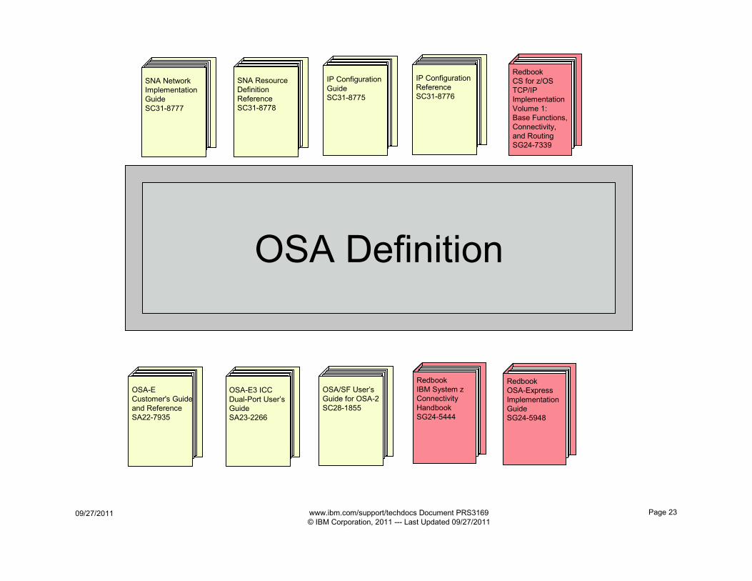
OSA Definition
SNA Network
Implementation
Guide
SC31-8777
Redbook
CS for z/OS
TCP/IP
Implementation
Volume 1:
Base Functions,
Connectivity,
and Routing
SG24-7339
SNA Resource
Definition
Reference
SC31-8778
IP Configuration
Guide
SC31-8775
IP Configuration
Reference
SC31-8776
Redbook
IBM System z
Connectivity
Handbook
SG24-5444
Redbook
OSA-Express
Implementation
Guide
SG24-5948
OSA-E
Customer's Guide
and Reference
SA22-7935
OSA-E3 ICC
Dual-Port User’s
Guide
SA23-2266
OSA/SF User’s
Guide for OSA-2
SC28-1855
09/27/2011 www.ibm.com/support/techdocs Document PRS3169
© IBM Corporation, 2011 --- Last Updated 09/27/2011
Page 24
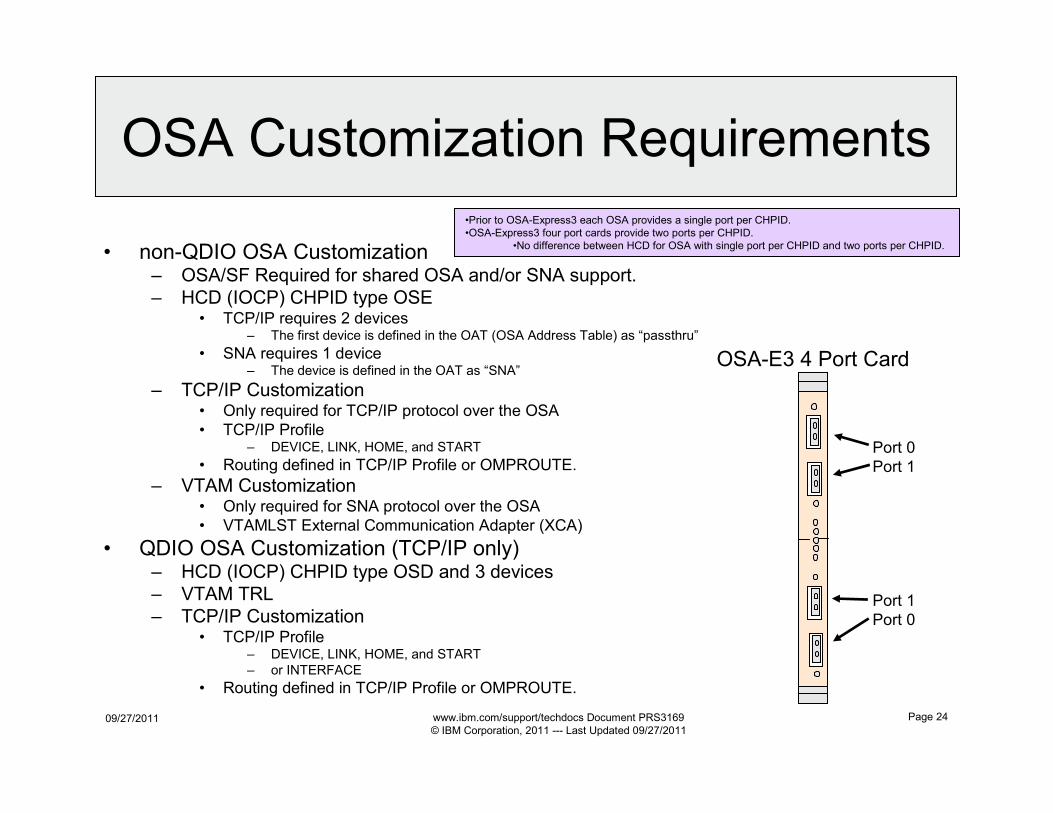
OSA Customization Requirements
• non-QDIO OSA Customization– OSA/SF Required for shared OSA and/or SNA support.
– HCD (IOCP) CHPID type OSE• TCP/IP requires 2 devices
– The first device is defined in the OAT (OSA Address Table) as “passthru”
• SNA requires 1 device– The device is defined in the OAT as “SNA”
– TCP/IP Customization• Only required for TCP/IP protocol over the OSA
• TCP/IP Profile– DEVICE, LINK, HOME, and START
• Routing defined in TCP/IP Profile or OMPROUTE.
– VTAM Customization• Only required for SNA protocol over the OSA
• VTAMLST External Communication Adapter (XCA)
• QDIO OSA Customization (TCP/IP only)– HCD (IOCP) CHPID type OSD and 3 devices
– VTAM TRL
– TCP/IP Customization• TCP/IP Profile
– DEVICE, LINK, HOME, and START
– or INTERFACE
• Routing defined in TCP/IP Profile or OMPROUTE.
•Prior to OSA-Express3 each OSA provides a single port per CHPID.
•OSA-Express3 four port cards provide two ports per CHPID.
•No difference between HCD for OSA with single port per CHPID and two ports per CHPID.
OSA-E3 4 Port Card
Port 0
Port 1
Port 1
Port 0
09/27/2011 www.ibm.com/support/techdocs Document PRS3169
© IBM Corporation, 2011 --- Last Updated 09/27/2011
Page 25
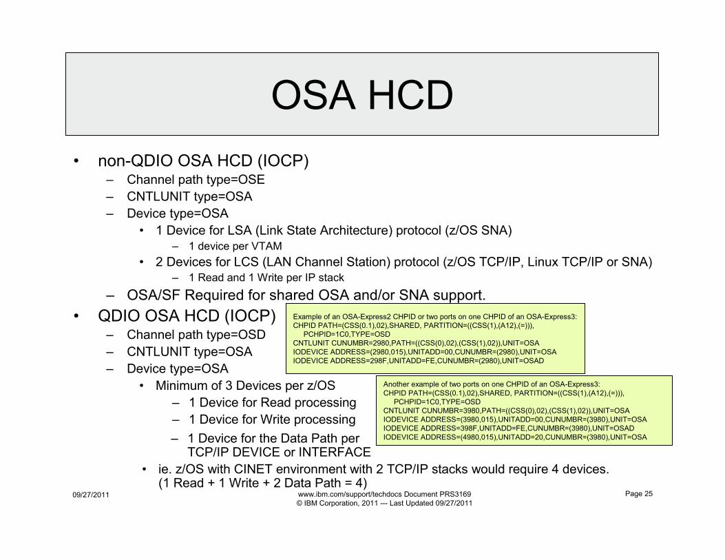
OSA HCD
• non-QDIO OSA HCD (IOCP)– Channel path type=OSE
– CNTLUNIT type=OSA
– Device type=OSA
• 1 Device for LSA (Link State Architecture) protocol (z/OS SNA)
– 1 device per VTAM
• 2 Devices for LCS (LAN Channel Station) protocol (z/OS TCP/IP, Linux TCP/IP or SNA)– 1 Read and 1 Write per IP stack
– OSA/SF Required for shared OSA and/or SNA support.
• QDIO OSA HCD (IOCP)– Channel path type=OSD
– CNTLUNIT type=OSA
– Device type=OSA
• Minimum of 3 Devices per z/OS
– 1 Device for Read processing
– 1 Device for Write processing
Example of an OSA-Express2 CHPID or two ports on one CHPID of an OSA-Express3:
CHPID PATH=(CSS(0.1),02),SHARED, PARTITION=((CSS(1),(A12),(=))),
PCHPID=1C0,TYPE=OSD
CNTLUNIT CUNUMBR=2980,PATH=((CSS(0),02),(CSS(1),02)),UNIT=OSA
IODEVICE ADDRESS=(2980,015),UNITADD=00,CUNUMBR=(2980),UNIT=OSA
IODEVICE ADDRESS=298F,UNITADD=FE,CUNUMBR=(2980),UNIT=OSAD
Another example of two ports on one CHPID of an OSA-Express3:
CHPID PATH=(CSS(0.1),02),SHARED, PARTITION=((CSS(1),(A12),(=))),
PCHPID=1C0,TYPE=OSD
CNTLUNIT CUNUMBR=3980,PATH=((CSS(0),02),(CSS(1),02)),UNIT=OSA
IODEVICE ADDRESS=(3980,015),UNITADD=00,CUNUMBR=(3980),UNIT=OSA
IODEVICE ADDRESS=398F,UNITADD=FE,CUNUMBR=(3980),UNIT=OSAD
IODEVICE ADDRESS=(4980,015),UNITADD=20,CUNUMBR=(3980),UNIT=OSA– 1 Device for the Data Path per TCP/IP DEVICE or INTERFACE
• ie. z/OS with CINET environment with 2 TCP/IP stacks would require 4 devices. (1 Read + 1 Write + 2 Data Path = 4)
09/27/2011 www.ibm.com/support/techdocs Document PRS3169
© IBM Corporation, 2011 --- Last Updated 09/27/2011
Page 26
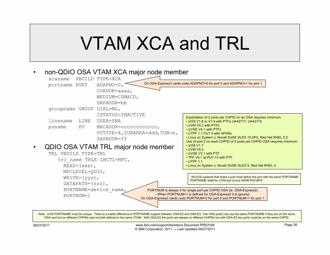
VTAM XCA and TRL
• non-QDIO OSA VTAM XCA major node memberxcaname VBUILD TYPE=XCA
portname PORT ADAPNO=0,
CUADDR=aaaa,
MEDIUM=CSMACD,
SAPADDR=bb
groupname GROUP DIAL=NO,
ISTATUS=INACTIVE
linename LINE USER=SNA
puname PU MACADDR=cccccccccccc,
PUTYPE=4,SUBAREA=ddd,TGN=e,
SAPADDR=ff
Exploitation of 2 ports per CHPID on an OSA requires minimum:
• z/OS V1.8 or V1.9 with PTFs UA42717, UA42716
• z/VM V5.2 with PTFs
• z/VSE V4.1 with PTFs
• z/TPF 1.1 PUT 4 with APARs
• Linux on System z: Novell SUSE SLES 10 SP2, Red Hat RHEL 5.2
Use of port 0 on each CHPID of 2 ports per CHPID OSA requires minimum:
• z/OS V1.7
• z/VM V5.2
• z/VSE V3.1 with PTF
• TPF V4.1 at PUT 13 with PTF
• z/TPF 1.1
• Linux on System z: Novell SUSE SLES 9, Red Hat RHEL 4
• QDIO OSA VTAM TRL major node memberTRL VBUILD TYPE=TRL
trl_name TRLE LNCTL=MPC,
READ=(xxx),
MPCLEVEL=QDIO,
WRITE=(yyy),
DATAPATH=(zzz),
PORTNAME=device_name,
PORTNUM=1
On OSA-Express3 cards code ADAPNO=0 for port 0 and ADAPNO=1 for port 1.
PORTNUM is always 0 for single port per CHPID OSA (ie. OSA-Express2).
–When PORTNUM=1 is defined for OSA-Express2 it is ignored.
On OSA-Express3 cards code PORTNUM=0 for port 0 and PORTNUM=1 for port 1.
Note: z/OS PORTNAME must be unique. There is a subtle difference in PORTNAME support between OSA-E2 and OSA-E3. Two OSA ports may use the same PORTNAME if they are on the same
OSA card but on different CHPIDs and not both defined to the same VTAM. With OSA-E2 the ports are always on different CHPIDs but with OSA-E3 two ports could be on the same CHPID.
All z/OS systems that share a port must define the port with the same PORTNAME.
PORTNAME relief for z/VM and zLinux APAR PQ73878
09/27/2011 www.ibm.com/support/techdocs Document PRS3169
© IBM Corporation, 2011 --- Last Updated 09/27/2011
Page 27
OSA TCP/IP Device and Interface
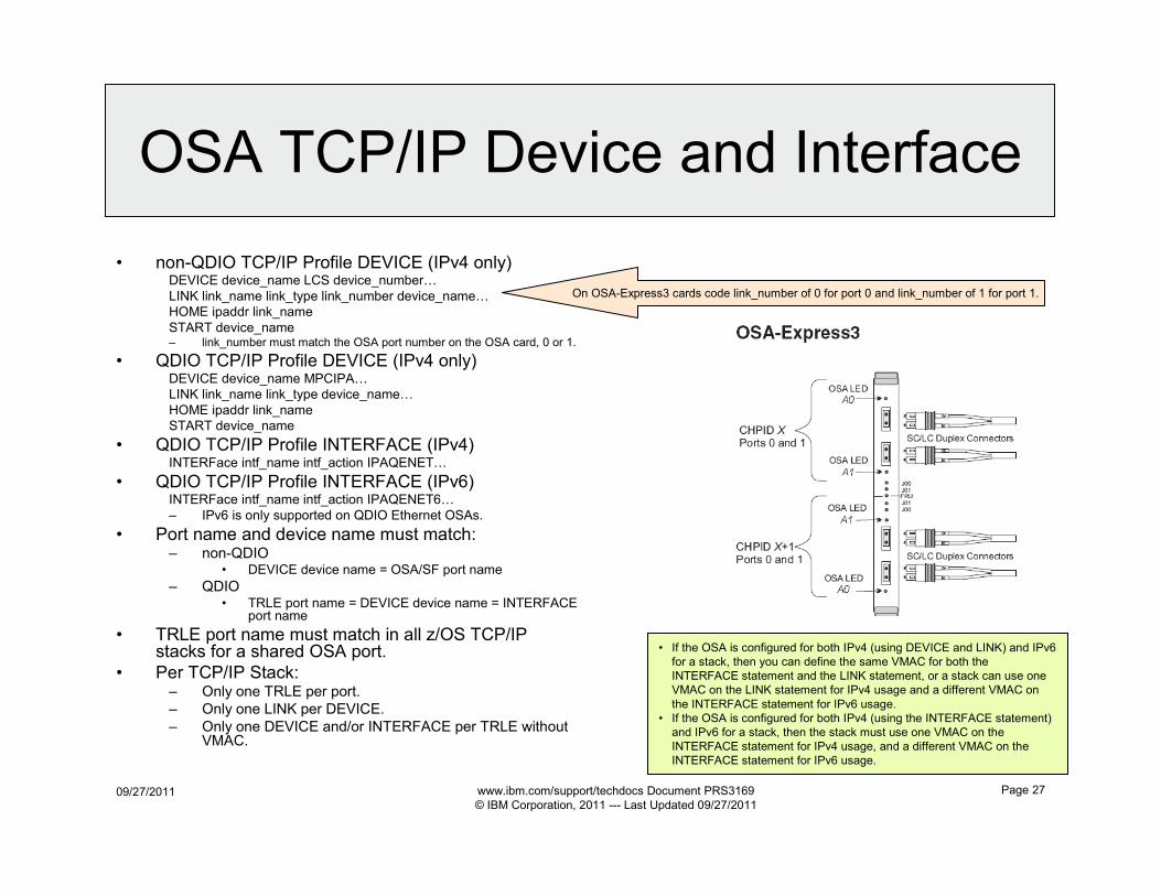
• non-QDIO TCP/IP Profile DEVICE (IPv4 only)DEVICE device_name LCS device_number…
LINK link_name link_type link_number device_name…
HOME ipaddr link_name
START device_name– link_number must match the OSA port number on the OSA card, 0 or 1.
• QDIO TCP/IP Profile DEVICE (IPv4 only)DEVICE device_name MPCIPA…
LINK link_name link_type device_name…
HOME ipaddr link_name
START device_name
• QDIO TCP/IP Profile INTERFACE (IPv4)INTERFace intf_name intf_action IPAQENET…
• QDIO TCP/IP Profile INTERFACE (IPv6)INTERFace intf_name intf_action IPAQENET6…
– IPv6 is only supported on QDIO Ethernet OSAs.
• Port name and device name must match:– non-QDIO
• DEVICE device name = OSA/SF port name
– QDIO• TRLE port name = DEVICE device name = INTERFACE
port name
• TRLE port name must match in all z/OS TCP/IP stacks for a shared OSA port.
• Per TCP/IP Stack:– Only one TRLE per port.
– Only one LINK per DEVICE.
– Only one DEVICE and/or INTERFACE per TRLE without VMAC.
On OSA-Express3 cards code link_number of 0 for port 0 and link_number of 1 for port 1.
• If the OSA is configured for both IPv4 (using DEVICE and LINK) and IPv6
for a stack, then you can define the same VMAC for both the
INTERFACE statement and the LINK statement, or a stack can use one
VMAC on the LINK statement for IPv4 usage and a different VMAC on
the INTERFACE statement for IPv6 usage.
• If the OSA is configured for both IPv4 (using the INTERFACE statement)
and IPv6 for a stack, then the stack must use one VMAC on the
INTERFACE statement for IPv4 usage, and a different VMAC on the
INTERFACE statement for IPv6 usage.
09/27/2011 www.ibm.com/support/techdocs Document PRS3169
© IBM Corporation, 2011 --- Last Updated 09/27/2011
Page 28
non-QDIO LCS and QDIO MPCIPA
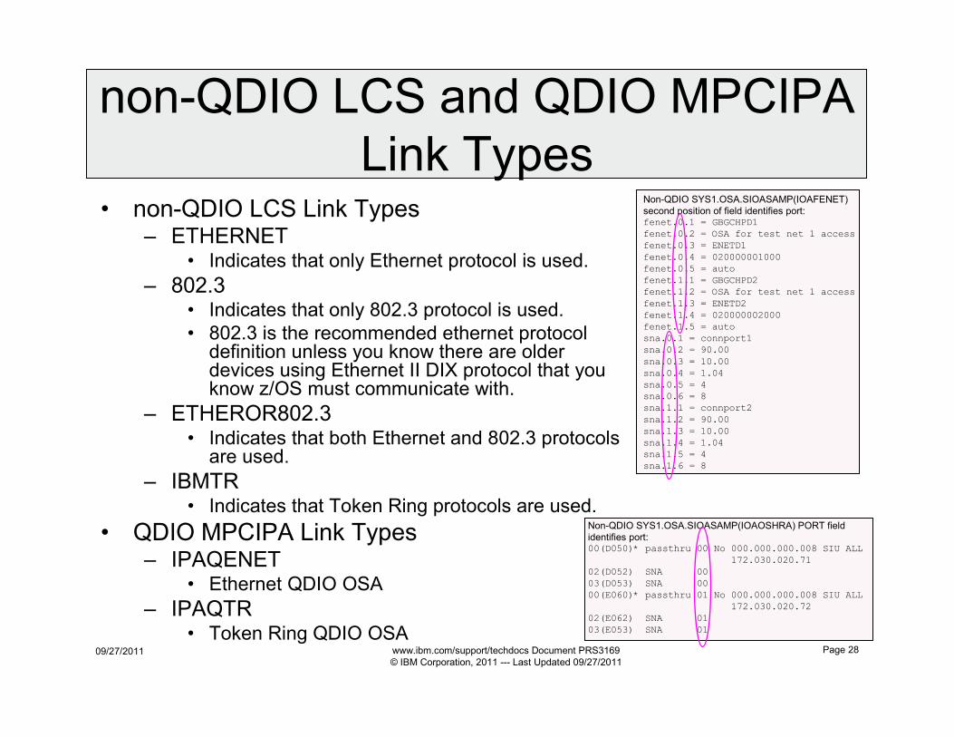
Link Types• non-QDIO LCS Link Types
– ETHERNET• Indicates that only Ethernet protocol is used.
– 802.3• Indicates that only 802.3 protocol is used.
• 802.3 is the recommended ethernet protocol definition unless you know there are older devices using Ethernet II DIX protocol that you know z/OS must communicate with.
– ETHEROR802.3• Indicates that both Ethernet and 802.3 protocols
are used.
– IBMTR• Indicates that Token Ring protocols are used.
• QDIO MPCIPA Link Types– IPAQENET
• Ethernet QDIO OSA
– IPAQTR• Token Ring QDIO OSA
Non-QDIO SYS1.OSA.SIOASAMP(IOAFENET)
second position of field identifies port:fenet.0.1 = GBGCHPD1
fenet.0.2 = OSA for test net 1 access
fenet.0.3 = ENETD1
fenet.0.4 = 020000001000
fenet.0.5 = auto
fenet.1.1 = GBGCHPD2
fenet.1.2 = OSA for test net 1 access
fenet.1.3 = ENETD2
fenet.1.4 = 020000002000
fenet.1.5 = auto
sna.0.1 = connport1
sna.0.2 = 90.00
sna.0.3 = 10.00
sna.0.4 = 1.04
sna.0.5 = 4
sna.0.6 = 8
sna.1.1 = connport2
sna.1.2 = 90.00
sna.1.3 = 10.00
sna.1.4 = 1.04
sna.1.5 = 4
sna.1.6 = 8
Non-QDIO SYS1.OSA.SIOASAMP(IOAOSHRA) PORT field
identifies port:00(D050)* passthru 00 No 000.000.000.008 SIU ALL
172.030.020.71
02(D052) SNA 00
03(D053) SNA 00
00(E060)* passthru 01 No 000.000.000.008 SIU ALL
172.030.020.72
02(E062) SNA 01
03(E053) SNA 01
09/27/2011 www.ibm.com/support/techdocs Document PRS3169
© IBM Corporation, 2011 --- Last Updated 09/27/2011
Page 29
Interface Action Types
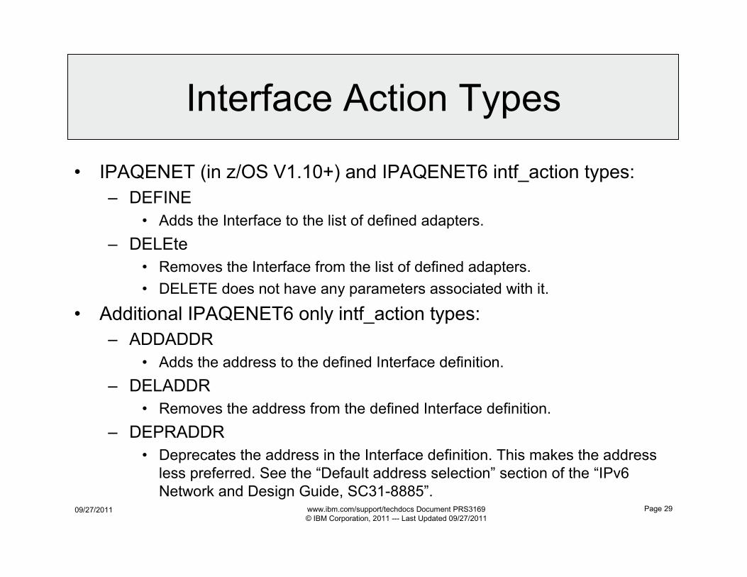
• IPAQENET (in z/OS V1.10+) and IPAQENET6 intf_action types:
– DEFINE
• Adds the Interface to the list of defined adapters.
– DELEte
• Removes the Interface from the list of defined adapters.
• DELETE does not have any parameters associated with it.
• Additional IPAQENET6 only intf_action types:
– ADDADDR
• Adds the address to the defined Interface definition.
– DELADDR
• Removes the address from the defined Interface definition.
– DEPRADDR
• Deprecates the address in the Interface definition. This makes the address
less preferred. See the “Default address selection” section of the “IPv6
Network and Design Guide, SC31-8885”.
09/27/2011 www.ibm.com/support/techdocs Document PRS3169
© IBM Corporation, 2011 --- Last Updated 09/27/2011
Page 30
Device/Link Syntax
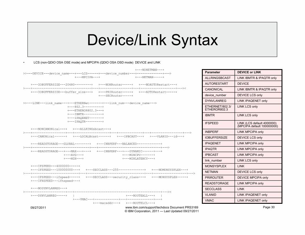
• LCS (non-QDIO OSA OSE mode) and MPCIPA (QDIO OSA OSD mode) DEVICE and LINK
+---NONETMAN---+
>>---DEVICE---device_name---+---LCS------+---device_number---+--------------+--->
+---MPCIPA---+ +---NETMAN-----+
+---IOBUFFERSIZE---20480---------+ +---NONRouter-----+ +---NOAUTORestart---+
>---+--------------------------------+---+-----------------+---+-------------------+---><
+---IOBUFFERSIZE---buffer_size---+ +---PRIRouter-----+ +---AUTORestart-----+
+---SECRouter-----+
>>---LINK---link_name---+---ETHERNet-------+---link_num---device_name--->
+---802.3----------+
+---ETHEROR802.3---+
+---IBMTR----------+
+---IPAQENET-------+
+---IPAQTR---------+
+---NONCANONical---+ +---ALLRINGsbcast---+
>---+------------------+---+-------------------+---+-------------+---+-----------------+--->
+---CANONical------+ +---LOCALBcast------+ +---IPBCAST---+ +---VLANID---id---+
+---READSTORAGE---GLOBAL--------+ +---INBPERF---BALANCED-------------+
>---+-------------------------------+---+----------------------------------+--->
+---READSTORAGE---+---MAX---+---+ +---INBPERF---+---DYNAMIC------+---+
+---AVG---+ +---MINCPU-------+
+---MIN---+ +---MINLATENCY---+
+---IFSPEED---4000000-----+
+---IFSPEED---100000000---+ +---SECCLASS---255--------------+ +---NOMONSYSPLEX---+
>---+-------------------------+---+-------------------------------+---+------------------+--->
+---IFSPEED---ifspeed-----+ +---SECCLASS---security_class---+ +---MONSYSPLEX-----+
+---IFHSPEED---ifhspeed---+
+---NODYNVLANREG---+
>---+------------------+---+-----------------------------------------------+---><
+---DYNVLANREG-----+ | +---ROUTEALL---+ |
+---VMAC---+-------------+---+--------------+---+
+---macaddr---+ +---ROUTELCL---+
LINK LCS onlyIBMTR
LINK MPCIPA onlyIPAQENET
LINK MPCIPA onlyIPAQTR
LINK LCS onlyETHERNET/802.3/ETHEROR802.3
DEVICE LCS onlyIOBUFFERSIZE
LINKSECCLASS
LINK MPCIPA onlyREADSTORAGE
DEVICE MPCIPA onlyPRIROUTER
LINKMONSYSPLEX
LINK MPCIPA onlyINBPERF
LINK IPAQENET onlyDYNVLANREG
LINK (LCS default 4000000) (MPCIPA default 100000000)
IFSPEED
DEVICE LCS onlydevice_number
DEVICEAUTORESTART
LINK IBMTR & IPAQTR onlyALLRINGSBCAST
LINK IBMTR & IPAQTR onlyCANONICAL
LINK IPAQENET onlyVLANID
LINK IPAQENET onlyVMAC
DEVICE LCS onlyNETMAN
LINK LCS onlylink_number
LINK MPCIPA onlyIPBCAST
DEVICE or LINKParameter
09/27/2011 www.ibm.com/support/techdocs Document PRS3169
© IBM Corporation, 2011 --- Last Updated 09/27/2011
Page 31
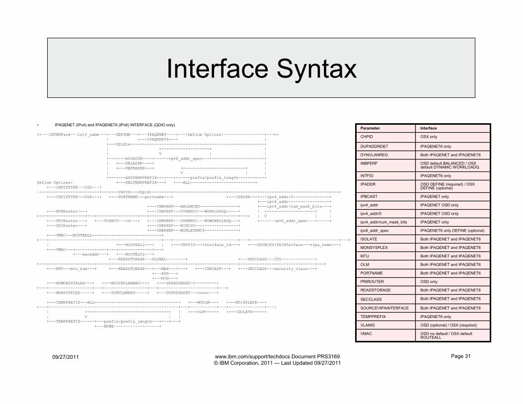
Interface Syntax
• IPAQENET (IPv4) and IPAQENET6 (IPv6) INTERFACE (QDIO only)
>>---INTERFace---intf_name---+---DEFINE---+---IPAQENET----+---|Define Options|-----------------+---><
| +---IPAQENET6---+ |
+---DELEte--------------------------------------------------------+
| +--------------------+ |
| V | |
+---+---ADDADDR----+------ipv6_addr_spec---+----------------------+
| +---DELADDR----+ |
| +---DEPRADDR---+ +--------------------------+ |
| V | |
+---+---ADDTEMPPREFIX---+---+------prefix/prefix_length---+---+---+
Define Options: +---DELTEMPPREFIX---+ +---ALL---------------------------+
+---CHPIDTYPE---OSD---+
|---+---------------------+---+---CHPID---chpid---------+----------------------+------------------------------------------+--->
+---CHPIDTYPE---OSX---+ +---PORTNAME---portname---+ +---IPADDR---+---ipv4_addr/0---------------+
+---ipv4_addr-----------------+
+---INBPERF---BALANCED----------------+ +---ipv4_addr/num_mask_bits---+
+---NONRouter---+ +---INBPERF---DYNAMIC---WORKLOADQ-----+ | +--------------------+ |
>---+---------------+---+-----------------+---+-------------------------------------+---> | V | |
+---PRIRouter---+ +---VLANID---id---+ +---INBPERF---DYNAMIC---NOWORKLOADQ---+ +------ipv6_addr_spec---+-----+
+---SECRouter---+ +---INBPERF---MINCPU------------------+
+---INBPERF---MINLATENCY--------------+
+---VMAC---ROUTEALL-----------------------------+
>---+-----------------------------------------------+---+---------------------------+---+-------------------------------------+--->
| +---ROUTEALL---+ | +---INTFID---interface_id---+ +---SOURCEVIPAINTerface---vipa_name---+
+---VMAC---+-------------+---+--------------+---+
+---macaddr---+ +---ROUTELCL---+
+---READSTORAGE---GLOBAL--------+ +---SECCLASS---255--------------+
>---+-------------------+-----+-------------------------------+---+-------------+---+-------------------------------+--->
+---MTU---mtu_num---+ +---READSTORAGE---+---MAX---+---+ +---IPBCAST---+ +---SECCLASS---security_class---+
+---AVG---+
+---MIN---+
+---NOMONSYSPLEX---+ +---NODYNVLANREG---+ +---DUPADDRDET—1---------+
>---+------------------+---+------------------+---+------------------------+--->
+---MONSYSPLEX-----+ +---DYNVLANREG-----+ +---DUPADDRDET---count---+
+---TEMPPREFIX---ALL-----------------------------------+ +---NOOLM---+ +---NOISOLATE---+
>---+------------------------------------------------------+---+-----------+---+---------------+---|
| +----------------------------------+ | +---OLM-----+ +---ISOLATE-----+
| V | |
+---TEMPPREFIX------+---prefix/prefix_length---+---+---+
+---NONE-------------------+
Both IPAQENET and IPAQENET6ISOLATE
Both IPAQENET and IPAQENET6MONSYSPLEX
Both IPAQENET and IPAQENET6MTU
Both IPAQENET and IPAQENET6OLM
Both IPAQENET and IPAQENET6PORTNAME
OSD onlyPRIROUTER
Both IPAQENET and IPAQENET6READSTORAGE
Both IPAQENET and IPAQENET6SECCLASS
Both IPAQENET and IPAQENET6SOURCEVIPAINTERFACE
IPAQENET6 onlyTEMPPREFIX
OSD (optional) / OSX (required)VLANID
OSD no default / OSX default ROUTEALL
VMAC
IPAQENET6 only DEFINE (optional)ipv6_addr_spec
IPAQENET6 onlyDUPADDRDET
IPAQENET6 onlyINTFID
Both IPAQENET and IPAQENET6DYNVLANREG
IPAQENET onlyIPBCAST
OSD default BALANCED / OSX default DYNAMIC WORKLOADQ
INBPERF
OSD DEFINE (required) / OSX DEFINE (optional)
IPADDR
OSX onlyCHPID
IPAQENET onlyipv4_addr/num_mask_bits
IPAQENET OSD onlyipv4_addr/0
IPAQENET OSD onlyipv4_addr
InterfaceParameter
09/27/2011 www.ibm.com/support/techdocs Document PRS3169
© IBM Corporation, 2011 --- Last Updated 09/27/2011
Page 32
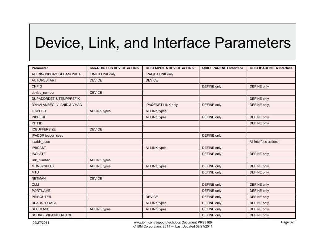
Device, Link, and Interface Parameters
DEVICEIOBUFFERSIZE
DEVICENETMAN
DEFINE onlyDEFINE onlyOLM
DEFINE onlyDEFINE onlyISOLATE
DEFINE onlyDEFINE onlyCHPID
DEFINE only
DEFINE only
DEFINE only
DEFINE only
DEFINE only
DEFINE only
DEFINE only
DEFINE only
DEFINE only
DEFINE only
DEFINE only
QDIO IPAQENET Interface
DEFINE onlyINTFID
DEFINE onlyAll LINK typesAll LINK typesSECCLASS
DEFINE onlyAll LINK typesREADSTORAGE
DEFINE onlyDEVICEPRIROUTER
DEFINE onlyPORTNAME
DEFINE onlyMTU
DEFINE onlyAll LINK typesAll LINK typesMONSYSPLEX
All interface actionsipaddr_spec
DEFINE onlyAll LINK typesINBPERF
DEFINE onlyIPAQENET LINK onlyDYNVLANREG, VLANID & VMAC
DEFINE onlyDUPADDRDET & TEMPPREFIX
All LINK typesAll LINK typesIFSPEED
DEVICEdevice_number
IPADDR ipaddr_spec
DEVICEDEVICEAUTORESTART
IPAQTR LINK onlyIBMTR LINK onlyALLRINGSBCAST & CANONICAL
All LINK typeslink_number
DEFINE onlySOURCEVIPAINTERFACE
All LINK typesIPBCAST
non-QDIO LCS DEVICE or LINK QDIO MPCIPA DEVICE or LINK QDIO IPAQENET6 InterfaceParameter
09/27/2011 www.ibm.com/support/techdocs Document PRS3169
© IBM Corporation, 2011 --- Last Updated 09/27/2011
Page 33
OSA TCP/IP
Device/Link/Interface
Parameter Descriptions
09/27/2011 www.ibm.com/support/techdocs Document PRS3169
© IBM Corporation, 2011 --- Last Updated 09/27/2011
Page 34
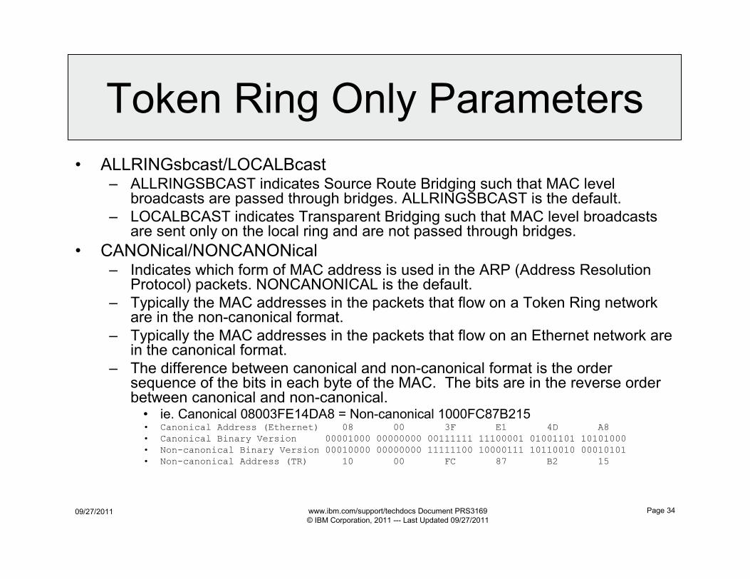
Token Ring Only Parameters
• ALLRINGsbcast/LOCALBcast– ALLRINGSBCAST indicates Source Route Bridging such that MAC level
broadcasts are passed through bridges. ALLRINGSBCAST is the default.
– LOCALBCAST indicates Transparent Bridging such that MAC level broadcasts are sent only on the local ring and are not passed through bridges.
• CANONical/NONCANONical– Indicates which form of MAC address is used in the ARP (Address Resolution
Protocol) packets. NONCANONICAL is the default.
– Typically the MAC addresses in the packets that flow on a Token Ring network are in the non-canonical format.
– Typically the MAC addresses in the packets that flow on an Ethernet network are in the canonical format.
– The difference between canonical and non-canonical format is the order sequence of the bits in each byte of the MAC. The bits are in the reverse order between canonical and non-canonical.• ie. Canonical 08003FE14DA8 = Non-canonical 1000FC87B215• Canonical Address (Ethernet) 08 00 3F E1 4D A8
• Canonical Binary Version 00001000 00000000 00111111 11100001 01001101 10101000
• Non-canonical Binary Version 00010000 00000000 11111100 10000111 10110010 00010101
• Non-canonical Address (TR) 10 00 FC 87 B2 15
09/27/2011 www.ibm.com/support/techdocs Document PRS3169
© IBM Corporation, 2011 --- Last Updated 09/27/2011
Page 35
INTERFACE Only Parameters
• CHPID chpid– Used to specify the CHPID for the interface. This value is a 2-character
hexadecimal value (00 - FF).
• ipaddr_spec– Specifies the ipv4_addr, ipv4_addr/mask, ipv6_addr, or prefix/prefix_length.
• MTU mtu_num– Specifies the maximum transmission unit (MTU) in bytes.
– IPCONFig PATHMTUDISCovery may be defined to dynamically discover the path MTU (PMTU), which is the smallest MTU of all the hops in the path. Use this parameter to prevent fragmentation of datagrams.• Uses ICMP “fragmentation-needed” errors to detect the PMTU for a path. ICMP errors
must be permitted to flow at all hosts along the path of a connection. PATHMTUDISCOVERY does not function if a firewall blocks ICMP errors.
• PORTNAME port_name– Port name and device name must match between TRLE, DEVICE, and
INTERFACE.
• SOURCEVIPAINTerface vipa_name– Specifies which static VIPA interface is to be used for SOURCEVIPA (when
IPCONFIG or IPCONFIG6 SOURCEVIPA is in effect).
09/27/2011 www.ibm.com/support/techdocs Document PRS3169
© IBM Corporation, 2011 --- Last Updated 09/27/2011
Page 36
INTERFACE IPv6 Only Parameters
• DUPADDRDET count_num– Specifies the number of times to attempt duplicate address detection.
• INTFID interface_id– Optional 64-bit interface identifier in colon-hexadecimal format.
– If specified, this interface ID is used to form the link-local address for the interface, and is also appended to any manually configured prefixes for the interface, to form complete IPv6 addresses on the interface.
– If you do not configure manual IP addresses on the interface, the INTFID value is appended to any prefixes learned over this interface by way of router advertisements.
– If not defined, TCP/IP builds the Interface ID using information returned from the OSA-Express Adapter (during Interface activation). The built Interface ID value is then used to form the link-local address. This value is also used to complete the formation of other IPv6 addresses on the interface, if you choose to configure only the prefix portion of the addresses (by way of IPADDR or ADDADDR). Also, if you do not configure manual IP addresses on the interface, the built interface ID value is appended to any prefixes learned over this interface by way of router advertisements.
• TEMPPREFIX ALL/NONE/prefix/prefix_length (Default is ALL)– ALL causes temporary addresses to be generated for all prefixes learned over this interface by router
advertisements.
– NONE causes no IPv6 temporary addresses are generated for this interface.
– prefix/prefix_length specifies the set of prefixes for which temporary IPv6 addresses can be generated.
– A temporary IPv6 address is generated when a router advertisement containing a prefix is processed and the prefix is included in one of the prefixes in the temporary prefix list.
– Temporary addresses are generated only on an interface that is enabled for stateless address autoconfiguration.
– Temporary addresses are generated only when the TEMPADDRS keyword is specified on the IPCONFIG6 statement.
– You must specify the job name of an application in the SRCIP statement block with a value of TEMPADDRS to cause a temporary IPv6 address to be preferred over a public IPv6 address as the source IP address for the application; otherwise, the default source address selection algorithm prefers public IPv6 addresses over temporary addresses.
09/27/2011 www.ibm.com/support/techdocs Document PRS3169
© IBM Corporation, 2011 --- Last Updated 09/27/2011
Page 37
PRIRouter, SECRouter, NONRouter
• All IP addresses in a TCP/IP HOME list are registered (dynamically downloaded) with the QDIO adapters.
– HOME changes are automatically sent to QDIO adapters.
• If the OSA receives any packets with its MAC as the destination and a destination IP address that is "unknown" (meaning not an IP address in the HOME list), then OSA does the following:
– If PRIRouter is defined (assuming the OSA is started to that stack) then all "unknown" packets are sent to the PRIRouter stack.
– If PRIRouter is not defined (the OSA is not started to any stack with PRIRouter)(could be that PRIRouter is coded but that OSA connection is down due to failure or other outage) then if SECRouter is coded all "unknown" packets are sent to the SECRouter stack. If multiple SECRouters then a random (unpredictable) stack with SECRouter coded will be sent the "unknown" packets.
• There is no way to set the order of precedence for the secondary routers.
• Multiple Secondary Routers are supported on Ethernet Only
– If only NONRouter is defined (or any PRIRouter and SECRouter connection are down due to failure or other outage) then all "unknown" packets are discarded by the OSA. NONROUTER is the default.
• Non-QDIO OSA (OSE mode) may define PRIROUTER and SECROUTER via OSA/SF.• IPCONFIG DATAGRAMFWD
– PRIRouter is used when traffic is routed through the stack to another stack. Keep in mind that if one stack is used to route to other stacks IPCONFIG DATAGRAMFWD is required.
• z/OS V1.6+ DATAGRAMFWD not required for Sysplex Distributor.
• If target TCP/IP stacks only have XCF connectivity, datagram forwarding still needs to be configured on the distributor as all packets originating from the target will be forwarded to the distributor.
• PRIRouter and VLAN ID– Packets with unknown IP addresses are passed to the “router” stack.
• If VLANID is specified then packets with unknown IP addresses are only passed to the “router” stack if the packets have a matching VLAN ID tag.
– Without VLANID• Across one hardware box (System z central processor complex (CPC)), PRIROUTER can only be specified in the profile of one TCP/IP
stack for the same OSA port.
– With VLANID• Across one hardware box (System z central processor complex (CPC)), PRIROUTER can only be specified in the profile of one TCP/IP
stack for the same OSA port for the same VLANID.
• PriRouter, SecRouter, NonRouter definition is ignored when VMAC parameter is defined.
– Recommendation: Use VMAC for shared OSA ports rather than PRIROUTER/SECROUTER.
09/27/2011 www.ibm.com/support/techdocs Document PRS3169
© IBM Corporation, 2011 --- Last Updated 09/27/2011
Page 38
DEVICE Only Parameters
• AUTORestart/NOAUTORestart– Specifying AUTORESTART causes TCP/IP to attempt reactivation following
most device-failure indications.
– Reactivation attempts are done every 30 seconds.
– The total amount of time reactivation attempts are done is determined by IPCONFig DEVRETRYDURation.
– NOAUTORESTART is the default.
• device_number– Specifies the hexadecimal device number.
– Only the first of the two device numbers is defined.• The READ address is defined.
• The WRITE address is READ+1.
• IOBUFFERSIZE buffer_size– Specifies the I/O buffer size.
– IOBUFFERSIZE must be the default size of 20,480 for OSA.
• NETMAN/NONETMAN– Specifies the device is a 3172 that supports IBM Enterprise-specific MIB
variables for the 3172.
09/27/2011 www.ibm.com/support/techdocs Document PRS3169
© IBM Corporation, 2011 --- Last Updated 09/27/2011
Page 39
LINK Only Parameters
• IFSPEED/IFHSPEED speed_num
– Estimate of the interface’s current bandwidth.
• IFSPEED in bits per second.
• IFHSPEED in one million bits per second.
– Until the interface is successfully started, this value is used by
SNMP as the value of the ifSpeed MIB object. After the interface
is successfully started, SNMP uses the actual speed reported by
the interface as the value of the ifSpeed MIB object. The value of
this parameter has no effect on the operation of the device.
• link_number
– Indicates the port number on the OSA. Ignored unless OSA-
Express3.
09/27/2011 www.ibm.com/support/techdocs Document PRS3169
© IBM Corporation, 2011 --- Last Updated 09/27/2011
Page 40
Inbound Blocking, Broadcasts, and
Sysplex Monitor Parameters• INBPERF
– Indicates how frequently the adapter should interrupt the host for inbound traffic.
– 3 static settings• MINCPU uses interrupt-timing value selected to minimize host interrupts without regard to throughput.
• MINLATENCY uses interrupt-timing value selected to minimize delay, by more quickly passing packets to the host.
• BALANCED uses interrupt-timing value selected to achieve high throughput and low CPU consumption. This is the default.
– 1 dynamic setting (New in z/OS V1.9, PTFed back to V1.8)• DYNAMIC reacts to changes in inbound traffic patterns and sets interrupt-timing values to where throughput is maximized.
• Only for OSA-Express2+ features on a System z9+ with the corresponding dynamic LAN idle functional support.– See the 2094DEVICE Preventive Service Planning (PSP) and the 2096DEVICE Preventive Service Planning (PSP) buckets for
more information about the level of OSA that supports this function.
• DYNAMIC should outperform the other three static settings for most workload combinations.
– INBPERF must match between LINK and INTERFACE for the same OSA.
• IPBCAST– Enables IP broadcasts over this link. Without IPBCAST no IP broadcast will be passed over this link.
• MONSYSPLEX/NOMONSYSPLEX– New in z/OS V1.8
– Specifies whether or not sysplex autonomics should monitor the link’s status.• MONINTERFACE is required on GLOBALCONFIG SYSPLEXMONITOR statement.
– Dynamic routes over this link may be monitored.• Requires MONSYSPLEX and DYNROUTE on the GLOBALCONFIG SYSPLEXMONITOR statement.
– NOMONSYSPLEX is the default.
– See VIPA presentation for more information about Sysplex Autonomics:• http://www.ibm.com/support/techdocs/atsmastr.nsf/WebIndex/PRS789
09/27/2011 www.ibm.com/support/techdocs Document PRS3169
© IBM Corporation, 2011 --- Last Updated 09/27/2011
Page 41
Security Class Parameter
• SECCLASS security_class
– Used for Multi-Level Security.
– Security class for IP filtering with this interface.
– The matching policy action is applied when the SECCLASS
parameter matches the SecurityClass parameter defined on the
policy IPsec condition IpService statement.
– TCP/IP stack ignores this value if IPSECURITY is not specified
on the IPCONFIG statement.
09/27/2011 www.ibm.com/support/techdocs Document PRS3169
© IBM Corporation, 2011 --- Last Updated 09/27/2011
Page 42
OSA Read Storage Usage
09/27/2011 www.ibm.com/support/techdocs Document PRS3169
© IBM Corporation, 2011 --- Last Updated 09/27/2011
Page 43
QDIO/iQDIO Read Storage
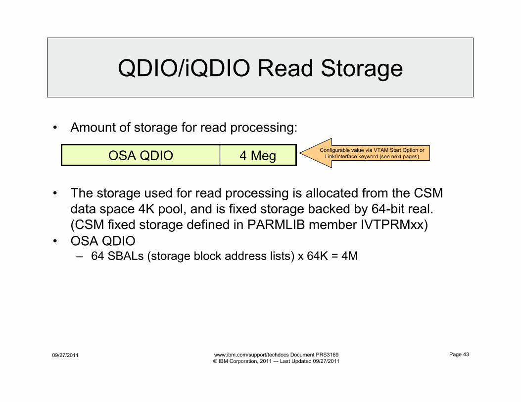
• Amount of storage for read processing:
• The storage used for read processing is allocated from the CSM
data space 4K pool, and is fixed storage backed by 64-bit real.
(CSM fixed storage defined in PARMLIB member IVTPRMxx)
• OSA QDIO– 64 SBALs (storage block address lists) x 64K = 4M
4 MegOSA QDIOConfigurable value via VTAM Start Option or
Link/Interface keyword (see next pages)
09/27/2011 www.ibm.com/support/techdocs Document PRS3169
© IBM Corporation, 2011 --- Last Updated 09/27/2011
Page 44
VTAM Start Options to Define Storage
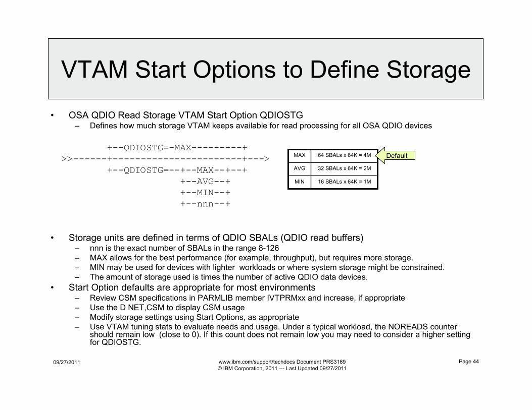
• OSA QDIO Read Storage VTAM Start Option QDIOSTG– Defines how much storage VTAM keeps available for read processing for all OSA QDIO devices
+--QDIOSTG=-MAX---------+>>------+-----------------------+--->
+--QDIOSTG=--+--MAX--+--+
+--AVG--++--MIN--+
+--nnn--+
• Storage units are defined in terms of QDIO SBALs (QDIO read buffers)– nnn is the exact number of SBALs in the range 8-126
– MAX allows for the best performance (for example, throughput), but requires more storage.
– MIN may be used for devices with lighter workloads or where system storage might be constrained.
– The amount of storage used is times the number of active QDIO data devices.
• Start Option defaults are appropriate for most environments– Review CSM specifications in PARMLIB member IVTPRMxx and increase, if appropriate
– Use the D NET,CSM to display CSM usage
– Modify storage settings using Start Options, as appropriate
– Use VTAM tuning stats to evaluate needs and usage. Under a typical workload, the NOREADS counter should remain low (close to 0). If this count does not remain low you may need to consider a higher setting for QDIOSTG.
16 SBALs x 64K = 1MMIN
32 SBALs x 64K = 2MAVG
64 SBALs x 64K = 4MMAX Default
09/27/2011 www.ibm.com/support/techdocs Document PRS3169
© IBM Corporation, 2011 --- Last Updated 09/27/2011
Page 45
Read Storage Parameter
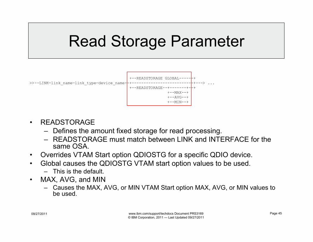
+--READSTORAGE GLOBAL------+
>>--LINK—link_name—link_type—device_name--+--------------------------+---> ...
+--READSTORAGE--+-------+--+
+--MAX--+
+--AVG--+
+--MIN--+
• READSTORAGE
– Defines the amount fixed storage for read processing.
– READSTORAGE must match between LINK and INTERFACE for the same OSA.
• Overrides VTAM Start option QDIOSTG for a specific QDIO device.
• Global causes the QDIOSTG VTAM start option values to be used.– This is the default.
• MAX, AVG, and MIN– Causes the MAX, AVG, or MIN VTAM Start option MAX, AVG, or MIN values to
be used.
09/27/2011 www.ibm.com/support/techdocs Document PRS3169
© IBM Corporation, 2011 --- Last Updated 09/27/2011
Page 46
Storage Shortage
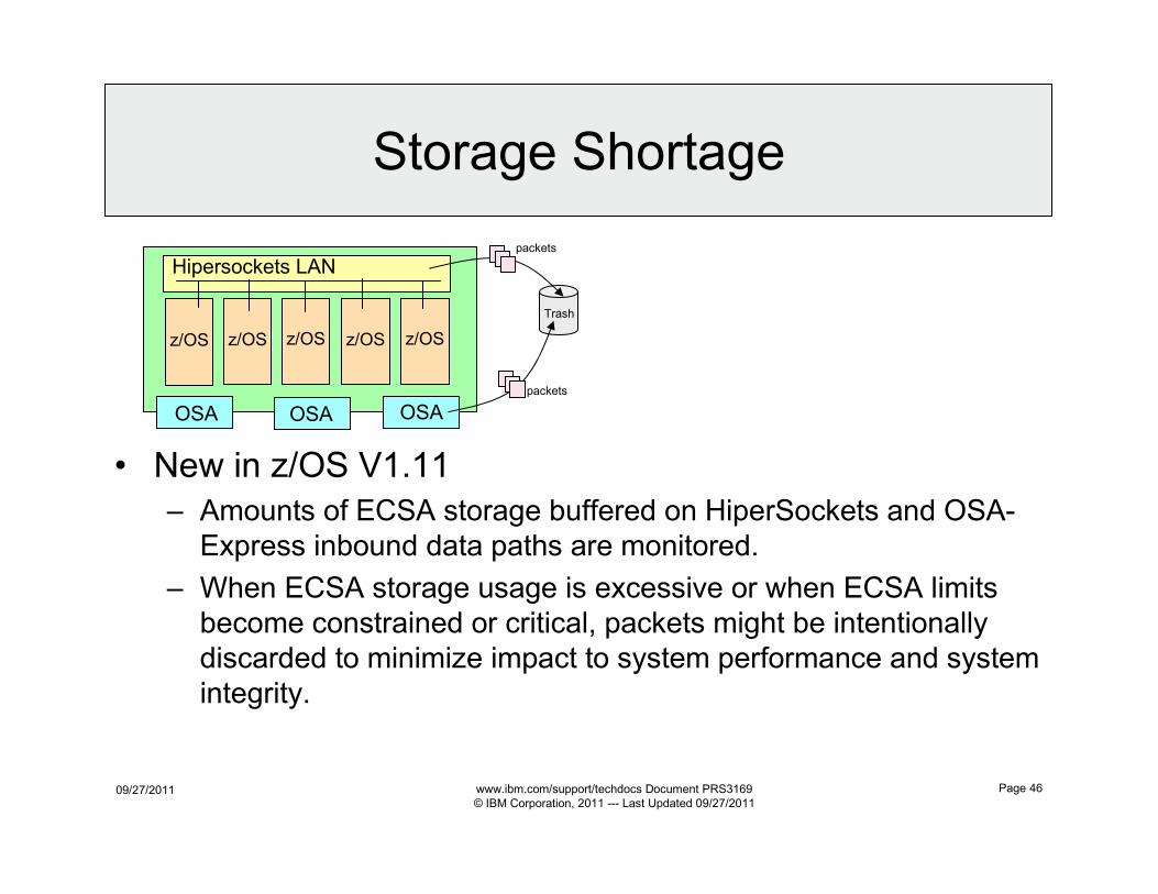
• New in z/OS V1.11
– Amounts of ECSA storage buffered on HiperSockets and OSA-
Express inbound data paths are monitored.
– When ECSA storage usage is excessive or when ECSA limits
become constrained or critical, packets might be intentionally
discarded to minimize impact to system performance and system
integrity.
Hipersockets LAN
z/OS z/OS z/OS z/OS z/OS
OSA OSA OSA
Trash
packets
packets
09/27/2011 www.ibm.com/support/techdocs Document PRS3169
© IBM Corporation, 2011 --- Last Updated 09/27/2011
Page 47
OSA VLAN Support
09/27/2011 www.ibm.com/support/techdocs Document PRS3169
© IBM Corporation, 2011 --- Last Updated 09/27/2011
Page 48
What is a VLAN?
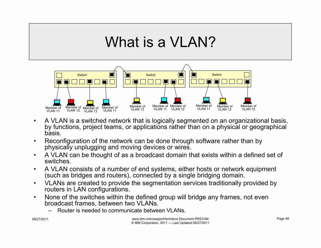
• A VLAN is a switched network that is logically segmented on an organizational basis, by functions, project teams, or applications rather than on a physical or geographical basis.
• Reconfiguration of the network can be done through software rather than by physically unplugging and moving devices or wires.
• A VLAN can be thought of as a broadcast domain that exists within a defined set of switches.
• A VLAN consists of a number of end systems, either hosts or network equipment (such as bridges and routers), connected by a single bridging domain.
• VLANs are created to provide the segmentation services traditionally provided by routers in LAN configurations.
• None of the switches within the defined group will bridge any frames, not even broadcast frames, between two VLANs.– Router is needed to communicate between VLANs.
Switch Switch Switch
Member ofVLAN 11
Member ofVLAN 11
Member ofVLAN 11
Member ofVLAN 11
Member ofVLAN 12
Member ofVLAN 12
Member ofVLAN 12
Member ofVLAN 13
Member ofVLAN 13Member of
VLAN 13
09/27/2011 www.ibm.com/support/techdocs Document PRS3169
© IBM Corporation, 2011 --- Last Updated 09/27/2011
Page 49
When z/OS is VLAN “un-aware”
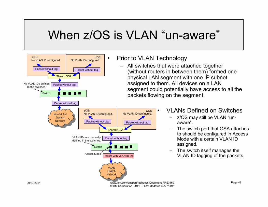
• Prior to VLAN Technology
– All switches that were attached together (without routers in between them) formed one physical LAN segment with one IP subnet assigned to them. All devices on a LAN segment could potentially have access to all the packets flowing on the segment.
Switch
Non-VLAN
Switch
Network
Non-VLAN
Switch
Network
z/OS
Shared OSA
z/OSNo VLAN ID configured. No VLAN ID configured.
Packet without tagNo VLAN IDs defined
In the switches.
Packet without tag
Packet without tag Packet without tag
Switch
VLAN
Switch
Network
VLAN
Switch
Network
z/OS
Shared OSA
Access Mode
z/OSNo VLAN ID configured. No VLAN ID configured.
Packet without tag
Packet with VLAN ID tag
VLAN IDs are manually
defined In the switches.
Packet without tagPacket without tag
• VLANs Defined on Switches– z/OS may still be VLAN “un-
aware”.
– The switch port that OSA attaches to should be configured in Access Mode with a certain VLAN ID assigned.
– The switch itself manages the VLAN ID tagging of the packets.
09/27/2011 www.ibm.com/support/techdocs Document PRS3169
© IBM Corporation, 2011 --- Last Updated 09/27/2011
Page 50
When z/OS is VLAN “aware”
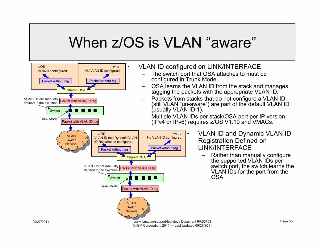
• VLAN ID configured on LINK/INTERFACE– The switch port that OSA attaches to must be
configured in Trunk Mode.
– OSA learns the VLAN ID from the stack and manages tagging the packets with the appropriate VLAN ID.
– Packets from stacks that do not configure a VLAN ID (still VLAN “un-aware”) are part of the default VLAN ID (usually VLAN ID 1).
– Multiple VLAN IDs per stack/OSA port per IP version (IPv4 or IPv6) requires z/OS V1.10 and VMACs.
Switch
VLAN
Switch
Network
VLAN
Switch
Network
z/OS
Shared OSA
Trunk Mode
z/OS
VLAN ID configured. No VLAN ID configured.
Packet with VLAN ID tag
VLAN IDs are manually
defined In the switches.Packet with VLAN ID tag
Packet without tagPacket without tag
Switch
VLAN
Switch
Network
VLAN
Switch
Network
z/OS
Shared OSA
Trunk Mode
z/OSVLAN ID and Dynamic VLAN
ID Registration configured.
No VLAN ID configured.
Packet with VLAN ID tag
VLAN IDs not manually
defined In the switches.Packet with VLAN ID tag
Packet without tagPacket without tag
• VLAN ID and Dynamic VLAN ID Registration Defined on LINK/INTERFACE– Rather than manually configure
the supported VLAN IDs per switch port, the switch learns the VLAN IDs for the port from the OSA.
09/27/2011 www.ibm.com/support/techdocs Document PRS3169
© IBM Corporation, 2011 --- Last Updated 09/27/2011
Page 51
QDIO VLAN and VMAC
Parameters
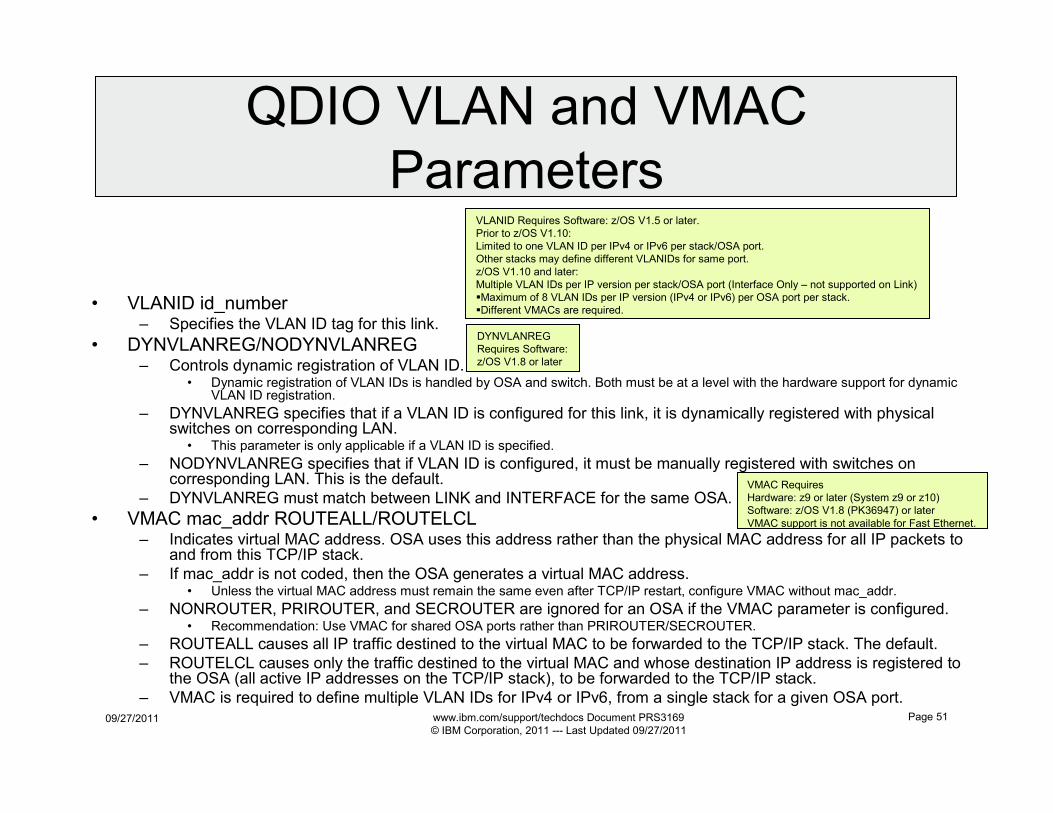
• VLANID id_number– Specifies the VLAN ID tag for this link.
• DYNVLANREG/NODYNVLANREG– Controls dynamic registration of VLAN ID.
• Dynamic registration of VLAN IDs is handled by OSA and switch. Both must be at a level with the hardware support for dynamic VLAN ID registration.
– DYNVLANREG specifies that if a VLAN ID is configured for this link, it is dynamically registered with physical switches on corresponding LAN.
• This parameter is only applicable if a VLAN ID is specified.
– NODYNVLANREG specifies that if VLAN ID is configured, it must be manually registered with switches on corresponding LAN. This is the default.
– DYNVLANREG must match between LINK and INTERFACE for the same OSA.
• VMAC mac_addr ROUTEALL/ROUTELCL– Indicates virtual MAC address. OSA uses this address rather than the physical MAC address for all IP packets to
and from this TCP/IP stack.
– If mac_addr is not coded, then the OSA generates a virtual MAC address.• Unless the virtual MAC address must remain the same even after TCP/IP restart, configure VMAC without mac_addr.
– NONROUTER, PRIROUTER, and SECROUTER are ignored for an OSA if the VMAC parameter is configured.• Recommendation: Use VMAC for shared OSA ports rather than PRIROUTER/SECROUTER.
– ROUTEALL causes all IP traffic destined to the virtual MAC to be forwarded to the TCP/IP stack. The default.
– ROUTELCL causes only the traffic destined to the virtual MAC and whose destination IP address is registered to the OSA (all active IP addresses on the TCP/IP stack), to be forwarded to the TCP/IP stack.
– VMAC is required to define multiple VLAN IDs for IPv4 or IPv6, from a single stack for a given OSA port.
VMAC Requires
Hardware: z9 or later (System z9 or z10)
Software: z/OS V1.8 (PK36947) or later
VMAC support is not available for Fast Ethernet.
DYNVLANREG
Requires Software:
z/OS V1.8 or later
VLANID Requires Software: z/OS V1.5 or later.
Prior to z/OS V1.10:
Limited to one VLAN ID per IPv4 or IPv6 per stack/OSA port.
Other stacks may define different VLANIDs for same port.
z/OS V1.10 and later:
Multiple VLAN IDs per IP version per stack/OSA port (Interface Only – not supported on Link)
�Maximum of 8 VLAN IDs per IP version (IPv4 or IPv6) per OSA port per stack.
�Different VMACs are required.
09/27/2011 www.ibm.com/support/techdocs Document PRS3169
© IBM Corporation, 2011 --- Last Updated 09/27/2011
Page 52
z/OS Support of VLAN IDs
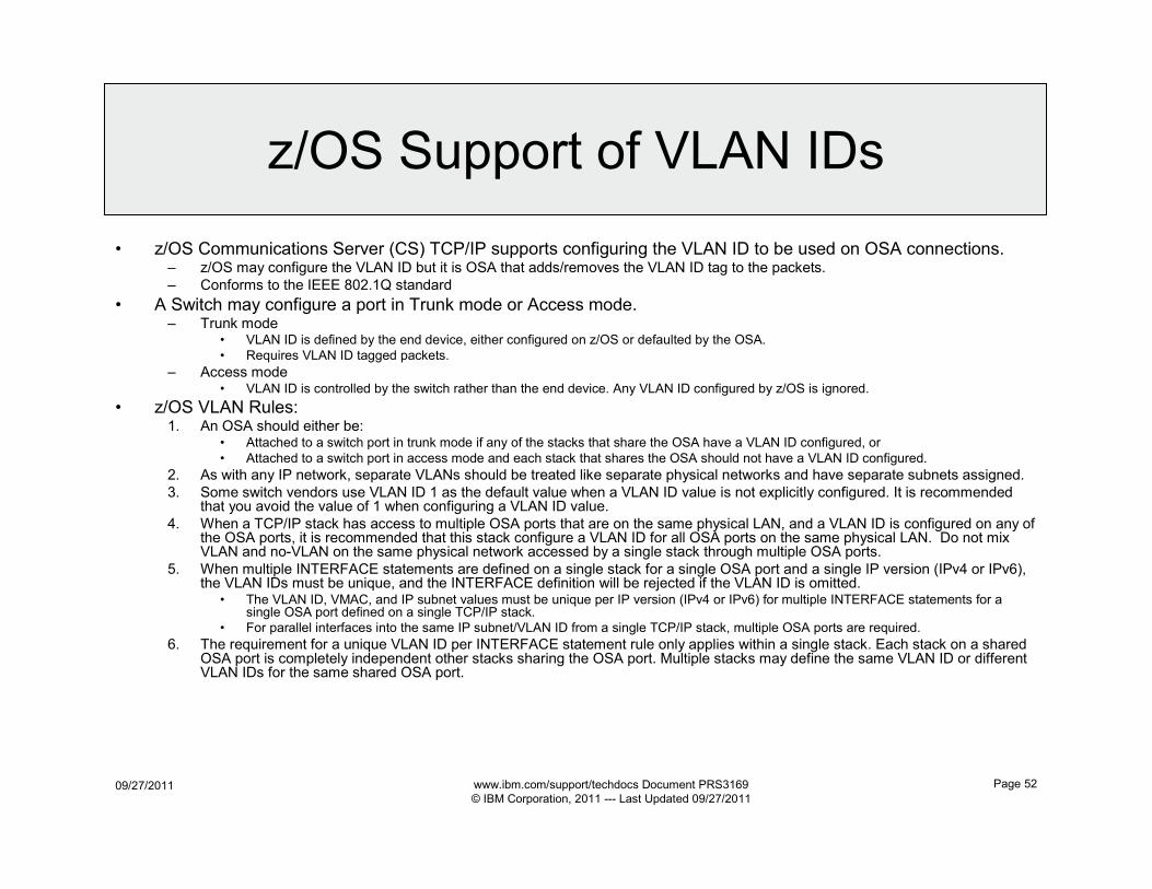
• z/OS Communications Server (CS) TCP/IP supports configuring the VLAN ID to be used on OSA connections.– z/OS may configure the VLAN ID but it is OSA that adds/removes the VLAN ID tag to the packets.
– Conforms to the IEEE 802.1Q standard
• A Switch may configure a port in Trunk mode or Access mode.– Trunk mode
• VLAN ID is defined by the end device, either configured on z/OS or defaulted by the OSA.
• Requires VLAN ID tagged packets.
– Access mode• VLAN ID is controlled by the switch rather than the end device. Any VLAN ID configured by z/OS is ignored.
• z/OS VLAN Rules:1. An OSA should either be:
• Attached to a switch port in trunk mode if any of the stacks that share the OSA have a VLAN ID configured, or
• Attached to a switch port in access mode and each stack that shares the OSA should not have a VLAN ID configured.
2. As with any IP network, separate VLANs should be treated like separate physical networks and have separate subnets assigned.
3. Some switch vendors use VLAN ID 1 as the default value when a VLAN ID value is not explicitly configured. It is recommended that you avoid the value of 1 when configuring a VLAN ID value.
4. When a TCP/IP stack has access to multiple OSA ports that are on the same physical LAN, and a VLAN ID is configured on any of the OSA ports, it is recommended that this stack configure a VLAN ID for all OSA ports on the same physical LAN. Do not mix VLAN and no-VLAN on the same physical network accessed by a single stack through multiple OSA ports.
5. When multiple INTERFACE statements are defined on a single stack for a single OSA port and a single IP version (IPv4 or IPv6), the VLAN IDs must be unique, and the INTERFACE definition will be rejected if the VLAN ID is omitted.
• The VLAN ID, VMAC, and IP subnet values must be unique per IP version (IPv4 or IPv6) for multiple INTERFACE statements for a single OSA port defined on a single TCP/IP stack.
• For parallel interfaces into the same IP subnet/VLAN ID from a single TCP/IP stack, multiple OSA ports are required.
6. The requirement for a unique VLAN ID per INTERFACE statement rule only applies within a single stack. Each stack on a shared OSA port is completely independent other stacks sharing the OSA port. Multiple stacks may define the same VLAN ID or different VLAN IDs for the same shared OSA port.
09/27/2011 www.ibm.com/support/techdocs Document PRS3169
© IBM Corporation, 2011 --- Last Updated 09/27/2011
Page 53
VLAN Migration
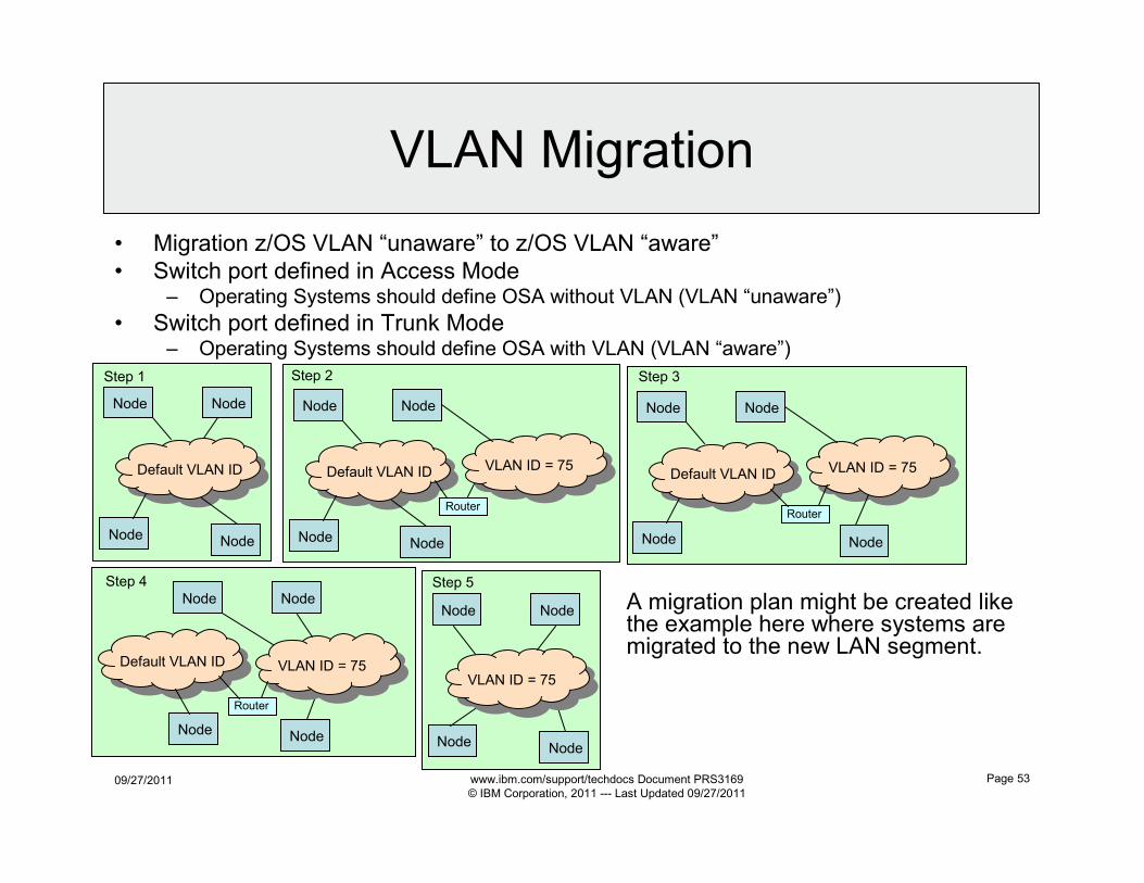
• Migration z/OS VLAN “unaware” to z/OS VLAN “aware”
• Switch port defined in Access Mode– Operating Systems should define OSA without VLAN (VLAN “unaware”)
• Switch port defined in Trunk Mode– Operating Systems should define OSA with VLAN (VLAN “aware”)
Node
Default VLAN ID
Node
NodeNode
Step 1
Node Node
NodeNode
VLAN ID = 75
Step 5
A migration plan might be created like the example here where systems are migrated to the new LAN segment.
Node
Default VLAN ID
Node
NodeNode
VLAN ID = 75
Step 2
Router
Node
Default VLAN ID
Node
NodeNode
VLAN ID = 75
Step 3
Router
Node
Default VLAN ID
Node
NodeNode
VLAN ID = 75
Step 4
Router
09/27/2011 www.ibm.com/support/techdocs Document PRS3169
© IBM Corporation, 2011 --- Last Updated 09/27/2011
Page 54
OSA Optimized Latency
Mode (OLM)
09/27/2011 www.ibm.com/support/techdocs Document PRS3169
© IBM Corporation, 2011 --- Last Updated 09/27/2011
Page 55
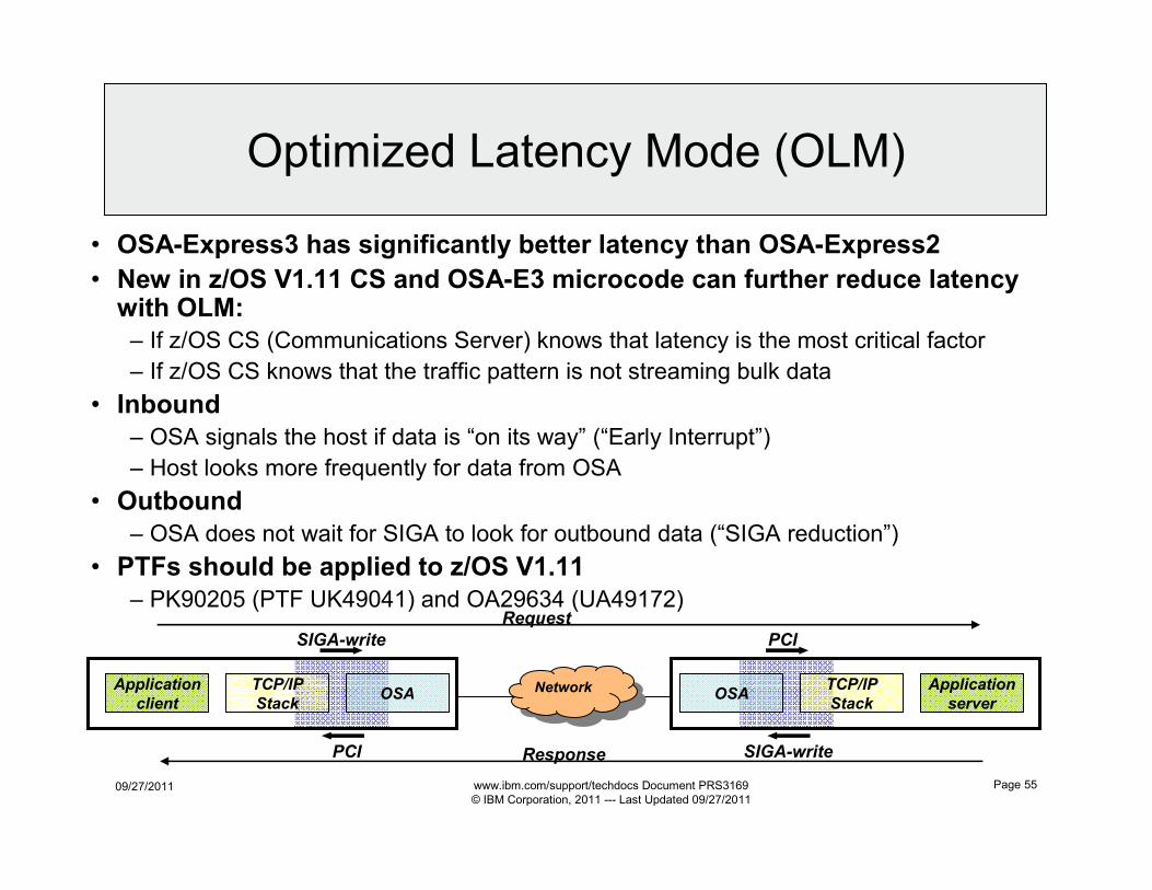
• OSA-Express3 has significantly better latency than OSA-Express2
• New in z/OS V1.11 CS and OSA-E3 microcode can further reduce latency with OLM:
– If z/OS CS (Communications Server) knows that latency is the most critical factor
– If z/OS CS knows that the traffic pattern is not streaming bulk data
• Inbound
– OSA signals the host if data is “on its way” (“Early Interrupt”)
– Host looks more frequently for data from OSA
• Outbound
– OSA does not wait for SIGA to look for outbound data (“SIGA reduction”)
• PTFs should be applied to z/OS V1.11
– PK90205 (PTF UK49041) and OA29634 (UA49172)
Application
client
Application
server
TCP/IP
Stack
TCP/IP
StackOSA OSANetwork
Network
SIGA-write PCI
SIGA-writePCI
Request
Response
Optimized Latency Mode (OLM)
09/27/2011 www.ibm.com/support/techdocs Document PRS3169
© IBM Corporation, 2011 --- Last Updated 09/27/2011
Page 56
• OLM is specified on the QDIO Interface statement.
Use of OLM
• Restrictions:
– Interfaces sharing an OSA port using OLM is limited to four
• 1,2, 3, or all 4 Interfaces may define OLM for a shared OSA.
– Each Interface statement counts toward the 4 Interface limit:• LPAR TCP/IP stack using the OSA port
• VLAN defined for this OSA port
• Protocol (IPv4 or IPv6) interface defined for this OSA port
• TCP/IP stack on the same LPAR using the OSA port
• TCP/IP stack activating the OSA-E Network Traffic Analyzer (OSAENTA)
• QDIO Accelerator or HiperSockets Accelerator will not accelerate traffic to or from an OSA
operating in OLM.
– GLOBALCONFIG WLMPRIORITYQ and QoS configuration
statement SETSUBNETPRIOTOSMASK may be necessary
to benefit from OLM.
• OLM will not change traffic patterns if all the traffic is being sent to
the fourth queue.
– When OLM is specified INBPERF is ignored and set to
DYNAMIC.
09/27/2011 www.ibm.com/support/techdocs Document PRS3169
© IBM Corporation, 2011 --- Last Updated 09/27/2011
Page 57
OSA Interface Isolation
09/27/2011 www.ibm.com/support/techdocs Document PRS3169
© IBM Corporation, 2011 --- Last Updated 09/27/2011
Page 58
Routing for Shared OSA
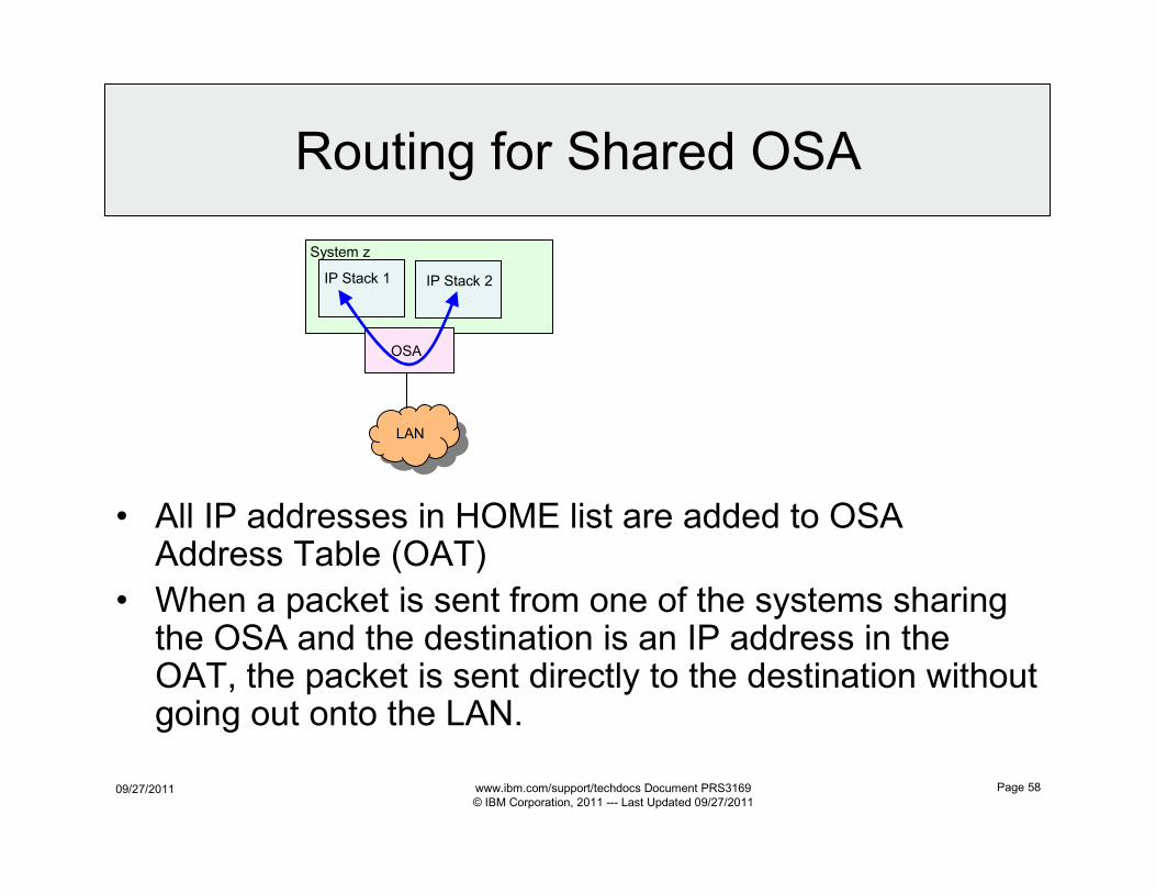
• All IP addresses in HOME list are added to OSA Address Table (OAT)
• When a packet is sent from one of the systems sharing the OSA and the destination is an IP address in the OAT, the packet is sent directly to the destination without going out onto the LAN.
System z
IP Stack 1 IP Stack 2
OSA
LAN
09/27/2011 www.ibm.com/support/techdocs Document PRS3169
© IBM Corporation, 2011 --- Last Updated 09/27/2011
Page 59
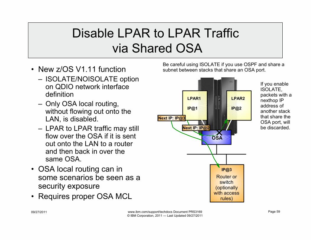
• New z/OS V1.11 function
– ISOLATE/NOISOLATE option on QDIO network interface definition
– Only OSA local routing, without flowing out onto the LAN, is disabled.
– LPAR to LPAR traffic may still flow over the OSA if it is sent out onto the LAN to a router and then back in over the same OSA.
• OSA local routing can in some scenarios be seen as a security exposure
• Requires proper OSA MCL
LPAR1 LPAR2
OSA
IP@1 IP@2
Next IP: IP@2
If you enable ISOLATE, packets with a nexthop IP address of another stack that share the OSA port, will be discarded.
Router or switch
(optionally with access
rules)
Be careful using ISOLATE if you use OSPF and share a subnet between stacks that share an OSA port.
Next IP: IP@3
IP@3
Disable LPAR to LPAR Traffic
via Shared OSA
09/27/2011 www.ibm.com/support/techdocs Document PRS3169
© IBM Corporation, 2011 --- Last Updated 09/27/2011
Page 60
OSA Error Support
09/27/2011 www.ibm.com/support/techdocs Document PRS3169
© IBM Corporation, 2011 --- Last Updated 09/27/2011
Page 61
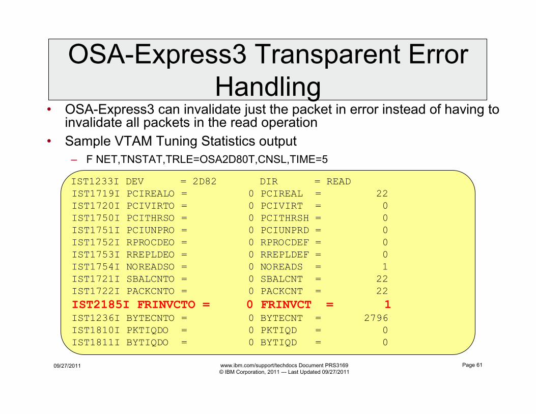
IST1233I DEV = 2D82 DIR = READ
IST1719I PCIREALO = 0 PCIREAL = 22
IST1720I PCIVIRTO = 0 PCIVIRT = 0
IST1750I PCITHRSO = 0 PCITHRSH = 0
IST1751I PCIUNPRO = 0 PCIUNPRD = 0
IST1752I RPROCDEO = 0 RPROCDEF = 0
IST1753I RREPLDEO = 0 RREPLDEF = 0
IST1754I NOREADSO = 0 NOREADS = 1
IST1721I SBALCNTO = 0 SBALCNT = 22
IST1722I PACKCNTO = 0 PACKCNT = 22
IST2185I FRINVCTO = 0 FRINVCT = 1
IST1236I BYTECNTO = 0 BYTECNT = 2796
IST1810I PKTIQDO = 0 PKTIQD = 0
IST1811I BYTIQDO = 0 BYTIQD = 0
• OSA-Express3 can invalidate just the packet in error instead of having to invalidate all packets in the read operation
• Sample VTAM Tuning Statistics output
– F NET,TNSTAT,TRLE=OSA2D80T,CNSL,TIME=5
OSA-Express3 Transparent Error
Handling
09/27/2011 www.ibm.com/support/techdocs Document PRS3169
© IBM Corporation, 2011 --- Last Updated 09/27/2011
Page 62
OSA TCP/IP
Considerations
09/27/2011 www.ibm.com/support/techdocs Document PRS3169
© IBM Corporation, 2011 --- Last Updated 09/27/2011
Page 63
Considerations
• OSA VIPA Limitations– OSA devices have a limit on the number of IP addresses (both IPv4 and IPv6 addresses) that can be
registered to the device. The limit is dependent on the microcode level of the OSA-Express device. This limit applies across all TCP/IP stacks that share the OSA-Express device. When defining a large number of VIPAs, take care not to exceed this limit. If the limit is exceeded, IP addresses beyond the limit will not be registered with the OSA-Express devices, and incoming packets with those IP addresses will not be routed to the correct stack unless that stack is designated as the primary router.
• RIP Routing and VIPA in Same (Sub)Network as OSAs– If using the RIP routing protocol and host route broadcasting is not supported by adjacent routers (that is,
adjacent routers are unable to learn host routes), the following restrictions for VIPA addresses must be applied in order to benefit from fault tolerance support:
• If you use subnetting and VIPA addresses are in the same network as the physical IP addresses, the subnetwork portion of any VIPA addresses must not be the subnetwork portion of any physical IP addresses in the network. In this case, assign a new subnetwork for the VIPA address.
• If subnetting is not used on any physical interface, the network portion of any VIPA address must not be the network portion of any physical IP address in the network. In this case, assign a new network for the VIPA address, preferably a class C network address.
– If using the RIP routing protocol and host route broadcasting is supported by adjacent routers (that is, adjacent routers are able to learn host routes), the network or subnetwork portions of VIPA addresses can be the same across multiple z/OS TCP/IP stacks in the network.
• Spanning Tree Protocol– If using a DVIPA when connecting an OSA-Express Gigabit Ethernet QDIO device to a intelligent bridge or
switch, ensure that the Spanning Tree Protocol (STP) on the intelligent bridge or switch is configured properly for DVIPA giveback and takeover operations. See the IP Configuration Guide for more details on STP problems.
• Port Fast Mode– If using VIPA in the same subnet as the OSA, along with an intelligent bridge or switch in access mode,
ensure that ’Port fast mode’ (Cisco) is enabled. This helps to decrease the amount of time the VIPA is unreachable in scenarios where there is dynamic movement of VIPA. For more information, see your bridge or switch manual.
09/27/2011 www.ibm.com/support/techdocs Document PRS3169
© IBM Corporation, 2011 --- Last Updated 09/27/2011
Page 64
Non-System z to/from zBX
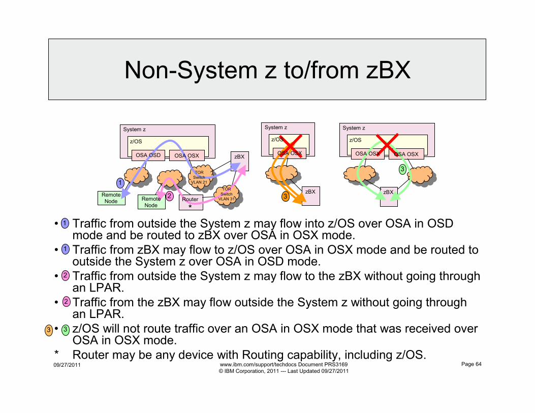
• Traffic from outside the System z may flow into z/OS over OSA in OSD mode and be routed to zBX over OSA in OSX mode.
• Traffic from zBX may flow to z/OS over OSA in OSX mode and be routed to outside the System z over OSA in OSD mode.
• Traffic from outside the System z may flow to the zBX without going through an LPAR.
• Traffic from the zBX may flow outside the System z without going through an LPAR.
• z/OS will not route traffic over an OSA in OSX mode that was received over OSA in OSX mode.
* Router may be any device with Routing capability, including z/OS.
Remote
Node
System z
z/OS
zBX
Remote
NodeRouter
*
TOR
Switch
VLAN 21
TOR
Switch
VLAN 31
OSA OSXOSA OSD
1
2
System z
z/OS
OSA OSX
zBX3
1
2
33
1
System z
OSA OSX
z/OS
OSA OSX
zBX
3
2
09/27/2011 www.ibm.com/support/techdocs Document PRS3169
© IBM Corporation, 2011 --- Last Updated 09/27/2011
Page 65
OMPROUTE OSPF Coding
• Optimize Performance– To minimize routing table size and advertisements that have to be processed, try to put z/OS and the sysplex into a stub or totally
stubby area or isolate areas with BGP or EIGRP.– To mimimize OSPF adjacencies, try to avoid OMPROUTE becoming the designated router.– Only use debug tracing when necessary.
• Use CTRACE tracing whenever possible.
• OSPF uses multicast packets– Disable multicast snooping on switches with shared OSAs attached to them.
• Point-to-Multipoint Networks– MPC, XCF, IUTSAMEH
– Unicast to Each Interface: Hello (Type 1)
– Does not require DR election
• Broadcast Multiaccess Network– Token Ring, Ethernet, FDDI, LANE, HiperSockets
– Multicast to 224.0.0.5: Hello (Type 1)
– Requires DR election
– OSPF_INTERFACE NON_BROADCAST=YES should not be defined.
• The HELLO protocol determines who the Designated Router (DR) will be.
• Role of the DR: – It is adjacent to all other routers on the network.
– It generates and floods the network link advertisements on behalf of the network.• Reduces amount of router protocol traffic, as only the DR is responsible for flooding the network with the information.
– It is responsible for maintaining the network topology database.
• Router with highest Router_Priority becomes DR on a broadcast multiaccess network.– If there is a tie, the router with the higher Router_ID becomes the DR.
– If the Router ID is not specified, the IP address of one of the OSPF interfaces will be used as Router ID.• Define IP address of static VIPA or physical interface for RouterID to avoid selection of a Dynamic VIPA which could move.
• If your z/OS system is not to be used primarily for routing, consider setting Router_Priority to 0 for all non-HiperSockets interfaces so that the system is ineligible to become the DR.
09/27/2011 www.ibm.com/support/techdocs Document PRS3169
© IBM Corporation, 2011 --- Last Updated 09/27/2011
Page 66
QDIO Accelerator
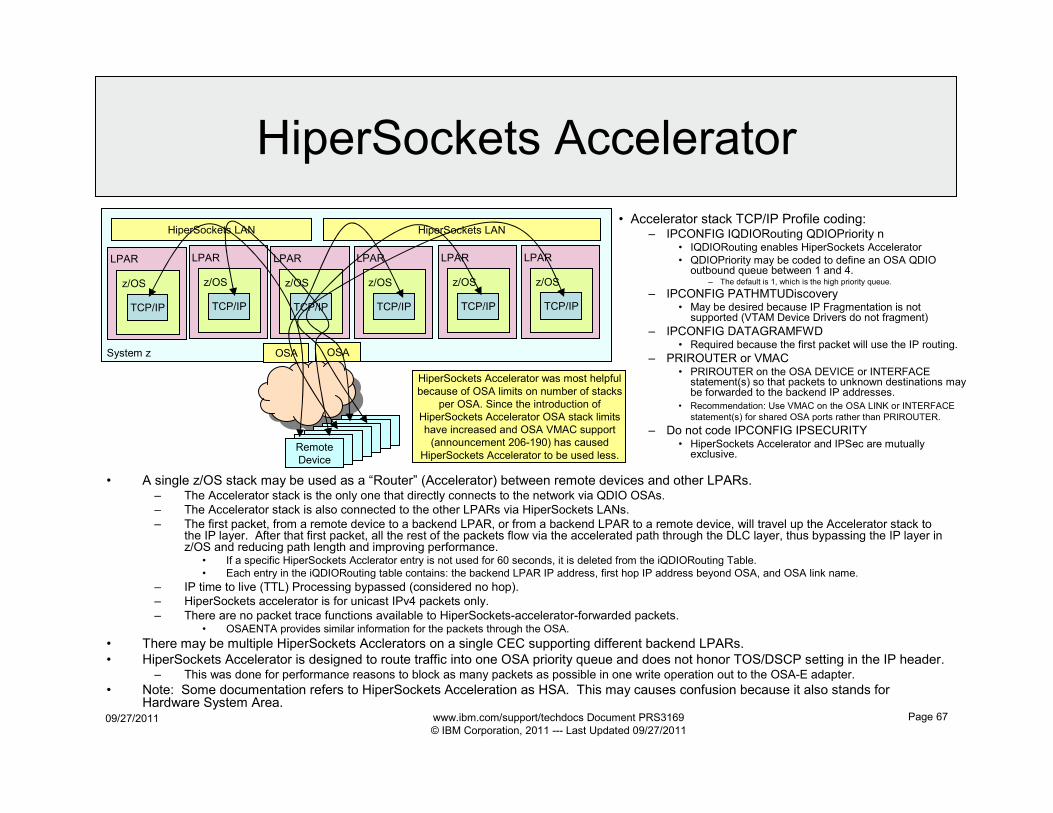
09/27/2011 www.ibm.com/support/techdocs Document PRS3169
© IBM Corporation, 2011 --- Last Updated 09/27/2011
Page 67
HiperSockets Accelerator
• A single z/OS stack may be used as a “Router” (Accelerator) between remote devices and other LPARs.– The Accelerator stack is the only one that directly connects to the network via QDIO OSAs.
– The Accelerator stack is also connected to the other LPARs via HiperSockets LANs.
– The first packet, from a remote device to a backend LPAR, or from a backend LPAR to a remote device, will travel up the Accelerator stack to the IP layer. After that first packet, all the rest of the packets flow via the accelerated path through the DLC layer, thus bypassing the IP layer in z/OS and reducing path length and improving performance.
• If a specific HiperSockets Acclerator entry is not used for 60 seconds, it is deleted from the iQDIORouting Table.
• Each entry in the iQDIORouting table contains: the backend LPAR IP address, first hop IP address beyond OSA, and OSA link name.
– IP time to live (TTL) Processing bypassed (considered no hop).
– HiperSockets accelerator is for unicast IPv4 packets only.
– There are no packet trace functions available to HiperSockets-accelerator-forwarded packets.• OSAENTA provides similar information for the packets through the OSA.
• There may be multiple HiperSockets Acclerators on a single CEC supporting different backend LPARs.
• HiperSockets Accelerator is designed to route traffic into one OSA priority queue and does not honor TOS/DSCP setting in the IP header.– This was done for performance reasons to block as many packets as possible in one write operation out to the OSA-E adapter.
• Note: Some documentation refers to HiperSockets Acceleration as HSA. This may causes confusion because it also stands for Hardware System Area.
System z
z/OS
TCP/IP
LPAR
z/OS
TCP/IP
LPAR
z/OS
TCP/IP
LPAR
z/OS
TCP/IP
LPAR
z/OS
TCP/IP
LPAR
z/OS
TCP/IP
LPAR
OSA OSA
HiperSockets LAN HiperSockets LAN
Remote
DeviceRemote
DeviceRemote
DeviceRemote
DeviceRemote
DeviceRemote
DeviceRemote
Device
• Accelerator stack TCP/IP Profile coding:– IPCONFIG IQDIORouting QDIOPriority n
• IQDIORouting enables HiperSockets Accelerator
• QDIOPriority may be coded to define an OSA QDIO outbound queue between 1 and 4.
– The default is 1, which is the high priority queue.
– IPCONFIG PATHMTUDiscovery• May be desired because IP Fragmentation is not
supported (VTAM Device Drivers do not fragment)
– IPCONFIG DATAGRAMFWD• Required because the first packet will use the IP routing.
– PRIROUTER or VMAC• PRIROUTER on the OSA DEVICE or INTERFACE
statement(s) so that packets to unknown destinations may be forwarded to the backend IP addresses.
• Recommendation: Use VMAC on the OSA LINK or INTERFACE
statement(s) for shared OSA ports rather than PRIROUTER.
– Do not code IPCONFIG IPSECURITY• HiperSockets Accelerator and IPSec are mutually
exclusive.
HiperSockets Accelerator was most helpful
because of OSA limits on number of stacks
per OSA. Since the introduction of
HiperSockets Accelerator OSA stack limits
have increased and OSA VMAC support
(announcement 206-190) has caused
HiperSockets Accelerator to be used less.
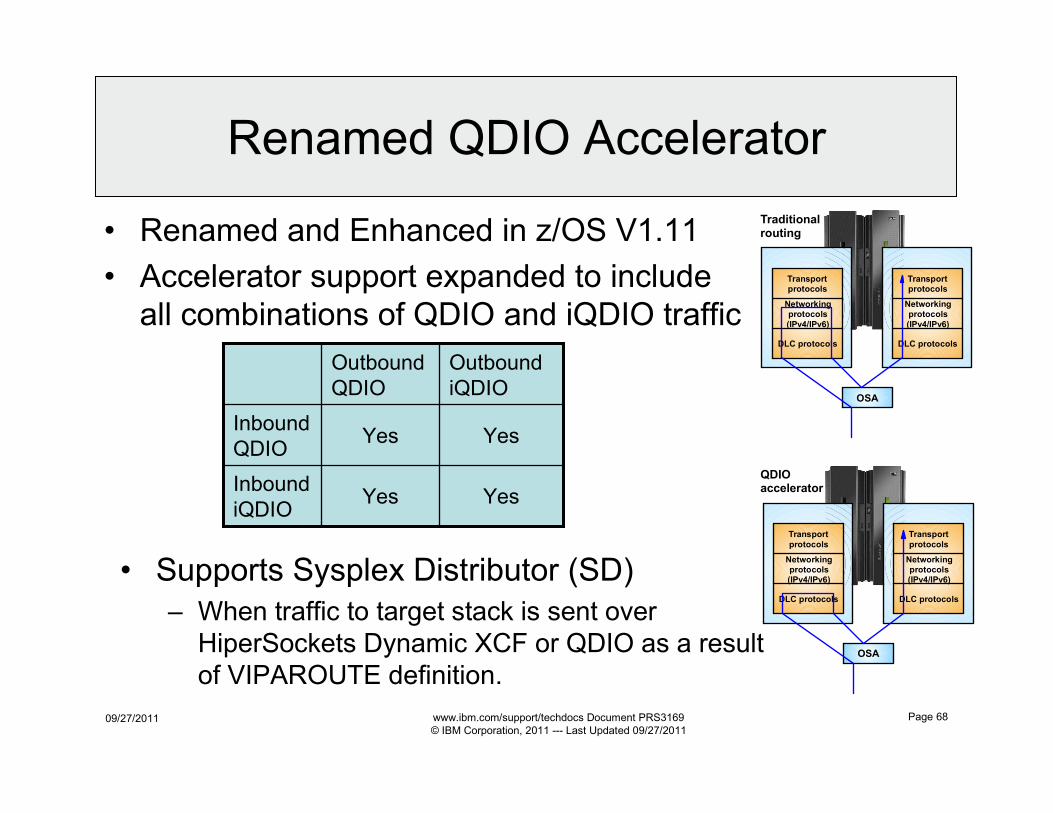
09/27/2011 www.ibm.com/support/techdocs Document PRS3169
© IBM Corporation, 2011 --- Last Updated 09/27/2011
Page 68
Renamed QDIO Accelerator
Transport protocols
Networking protocols
(IPv4/IPv6)
DLC protocols
OSA
Transport protocols
Networking protocols
(IPv4/IPv6)
DLC protocols
Traditional routing
Transport
protocols
Networking protocols (IPv4/IPv6)
DLC protocols
OSA
Transport
protocols
Networking protocols (IPv4/IPv6)
DLC protocols
QDIO accelerator
• Renamed and Enhanced in z/OS V1.11
• Accelerator support expanded to include
all combinations of QDIO and iQDIO traffic
YesYesInbound
iQDIO
YesYesInbound
QDIO
Outbound
iQDIO
Outbound
QDIO
• Supports Sysplex Distributor (SD)
– When traffic to target stack is sent over
HiperSockets Dynamic XCF or QDIO as a result
of VIPAROUTE definition.
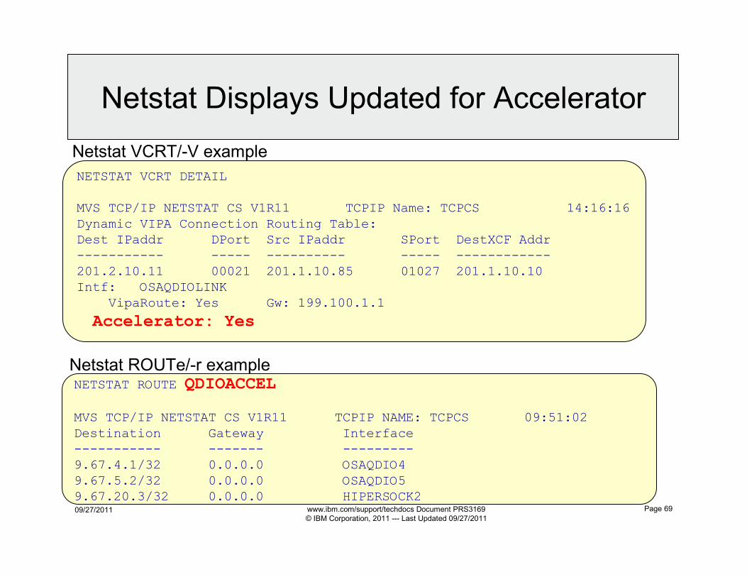
09/27/2011 www.ibm.com/support/techdocs Document PRS3169
© IBM Corporation, 2011 --- Last Updated 09/27/2011
Page 69
NETSTAT VCRT DETAIL
MVS TCP/IP NETSTAT CS V1R11 TCPIP Name: TCPCS 14:16:16
Dynamic VIPA Connection Routing Table: Dest IPaddr DPort Src IPaddr SPort DestXCF Addr
----------- ----- ---------- ----- ------------
201.2.10.11 00021 201.1.10.85 01027 201.1.10.10 Intf: OSAQDIOLINK
VipaRoute: Yes Gw: 199.100.1.1
Accelerator: Yes
NETSTAT ROUTE QDIOACCEL
MVS TCP/IP NETSTAT CS V1R11 TCPIP NAME: TCPCS 09:51:02
Destination Gateway Interface----------- ------- ---------
9.67.4.1/32 0.0.0.0 OSAQDIO4
9.67.5.2/32 0.0.0.0 OSAQDIO5 9.67.20.3/32 0.0.0.0 HIPERSOCK2
Netstat VCRT/-V example
Netstat Displays Updated for Accelerator
Netstat ROUTe/-r example
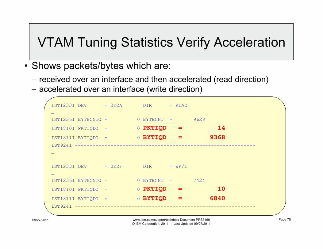
09/27/2011 www.ibm.com/support/techdocs Document PRS3169
© IBM Corporation, 2011 --- Last Updated 09/27/2011
Page 70
• Shows packets/bytes which are:
– received over an interface and then accelerated (read direction)
– accelerated over an interface (write direction)
IST1233I DEV = 0E2A DIR = READ
…
IST1236I BYTECNTO = 0 BYTECNT = 9628
IST1810I PKTIQDO = 0 PKTIQD = 14
IST1811I BYTIQDO = 0 BYTIQD = 9368
IST924I -------------------------------------------------------------
…
IST1233I DEV = 0E2F DIR = WR/1
…
IST1236I BYTECNTO = 0 BYTECNT = 7424
IST1810I PKTIQDO = 0 PKTIQD = 10
IST1811I BYTIQDO = 0 BYTIQD = 6840
IST924I -------------------------------------------------------------
VTAM Tuning Statistics Verify Acceleration
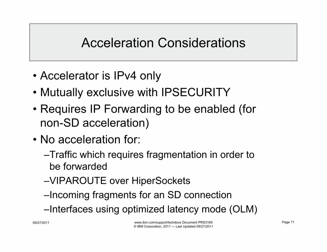
09/27/2011 www.ibm.com/support/techdocs Document PRS3169
© IBM Corporation, 2011 --- Last Updated 09/27/2011
Page 71
• Accelerator is IPv4 only
• Mutually exclusive with IPSECURITY
• Requires IP Forwarding to be enabled (for
non-SD acceleration)
• No acceleration for:
–Traffic which requires fragmentation in order to
be forwarded
–VIPAROUTE over HiperSockets
–Incoming fragments for an SD connection
–Interfaces using optimized latency mode (OLM)
Acceleration Considerations
09/27/2011 www.ibm.com/support/techdocs Document PRS3169
© IBM Corporation, 2011 --- Last Updated 09/27/2011
Page 72
Source IP Address
IP Configuration
Reference
SC31-8776
09/27/2011 www.ibm.com/support/techdocs Document PRS3169
© IBM Corporation, 2011 --- Last Updated 09/27/2011
Page 73
• Connections Initiated Inbound– When a connection is initiated from a remote node, the remote node sends a connection packet to a z/OS application.
• Typically the z/OS application swaps the source and destination IP address from the received packet to be used in the response packet.
• Typically the z/OS application takes the source IP address from the received packet and uses it as the destination IP address in the response packet.
• Typically the z/OS application takes the destination IP address from the received packet and uses it as the source IP address in the response packet.
• Connections Initiated Outbound– When a connection is initiated from a z/OS application the source IP address is determined by the source IP address selection algorithm.
• See “Source IP Address Selection” section in the IP Configuration Guide manual.
– When a connection is initiated from a z/OS application the destination IP address is either passed to the application in the connection command (ie. ftp 9.15.42.10) or is determined by domain name resolution of host name (ie. ftp wscftpsrv).
• Routing Table is used to send packet– Destination IP address is used with Routing Table (may contain a combination of static and dynamically learned routes), to determine which network path to send packet over.
Traffic Path In/Out of z/OS
09/27/2011 www.ibm.com/support/techdocs Document PRS3169
© IBM Corporation, 2011 --- Last Updated 09/27/2011
Page 74
• Connections Initiated Inbound– When a connection is initiated from a remote node, the remote node sends a connection packet to a z/OS application.
• Typically the z/OS application swaps the source and destination IP address from the received packet to be used in the response packet.
• Typically the z/OS application takes the source IP address from the received packet and uses it as the destination IP address in the response packet.
• Typically the z/OS application takes the destination IP address from the received packet and uses it as the source IP address in the response packet.
• Connections Initiated Outbound– When a connection is initiated from a z/OS application the source IP address is determined by the source IP address selection algorithm.
– When a connection is initiated from a z/OS application the destination IP address is either passed to the application in the connection command (ie. ftp 9.15.42.10) or is determined by domain name resolution of host name (ie. ftp wscftpsrv).
• Routing Table is used to send packet– Destination IP address is used with Routing Table (may contain a combination of static and dynamically learned routes), to determine which network path to send packet over.
Source and Destination IP Address
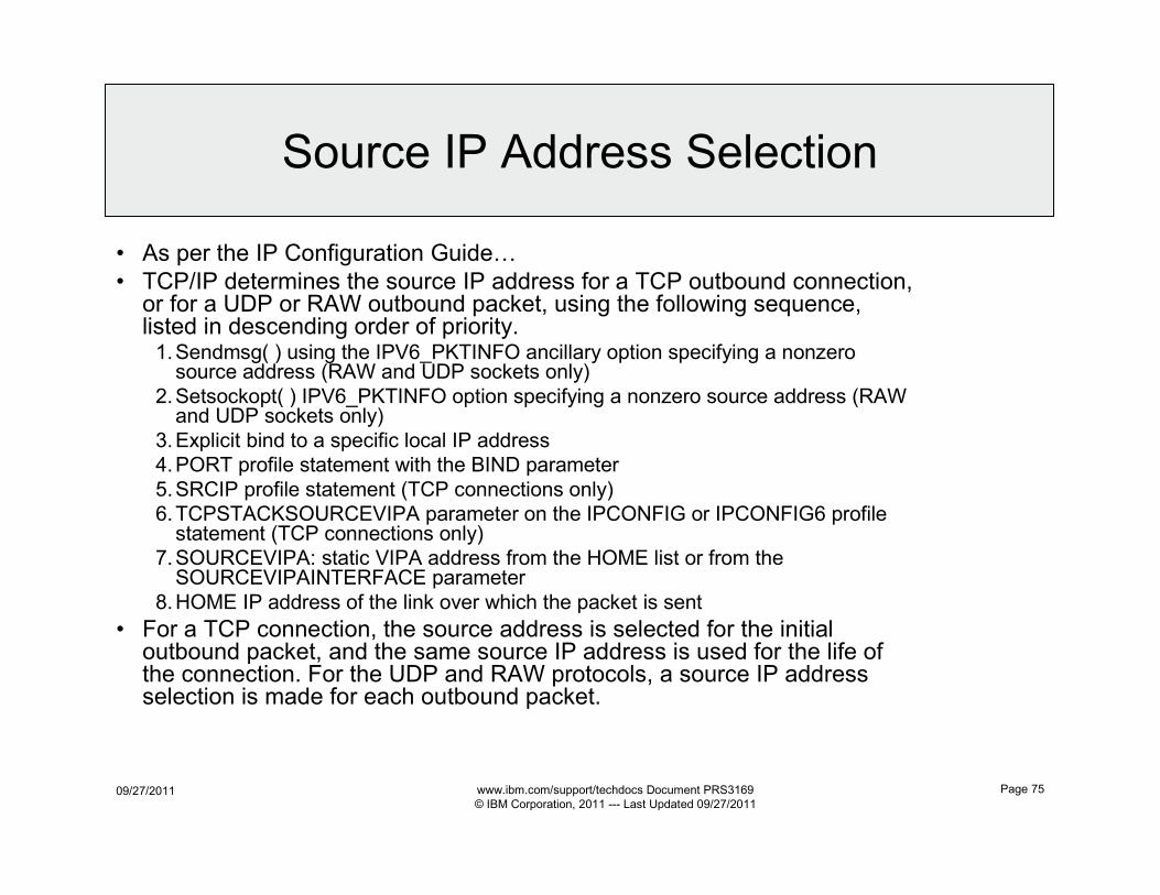
09/27/2011 www.ibm.com/support/techdocs Document PRS3169
© IBM Corporation, 2011 --- Last Updated 09/27/2011
Page 75
• As per the IP Configuration Guide…
• TCP/IP determines the source IP address for a TCP outbound connection, or for a UDP or RAW outbound packet, using the following sequence, listed in descending order of priority.1.Sendmsg( ) using the IPV6_PKTINFO ancillary option specifying a nonzerosource address (RAW and UDP sockets only)
2.Setsockopt( ) IPV6_PKTINFO option specifying a nonzero source address (RAWand UDP sockets only)
3.Explicit bind to a specific local IP address
4.PORT profile statement with the BIND parameter
5.SRCIP profile statement (TCP connections only)
6.TCPSTACKSOURCEVIPA parameter on the IPCONFIG or IPCONFIG6 profile statement (TCP connections only)
7.SOURCEVIPA: static VIPA address from the HOME list or from the SOURCEVIPAINTERFACE parameter
8.HOME IP address of the link over which the packet is sent
• For a TCP connection, the source address is selected for the initial outbound packet, and the same source IP address is used for the life of the connection. For the UDP and RAW protocols, a source IP address selection is made for each outbound packet.
Source IP Address Selection
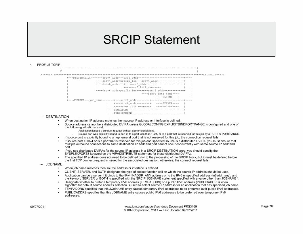
09/27/2011 www.ibm.com/support/techdocs Document PRS3169
© IBM Corporation, 2011 --- Last Updated 09/27/2011
Page 76
• PROFILE.TCPIP+-----------------------------------------------------------------------------------+
V |
>>---SRCIP------+---------------------------------------------------------------------------+---+---ENDSRCIP---><
+---DESTINATION---+---dstv4_addr---src4_addr----------------------------+---+
| +---dstv4_addr/prefix_len---srcv4_addr----------------+ |
| +---dstv6_addr---+---srcv6_addr--------+--------------+ |
| | +---srcv6_intf_name---+ | |
| +---dstv6_addr/prefix_len---+---srcv6_addr--------+---+ |
| +---srcv6_intf_name---+ |
| +---CLIENT---+ |
+---JOBNAME---job_name---+---+---srcv4_addr--------+---+------------+---+---+
| +---srcv6_addr--------+ +---SERVER---+ |
| +---srcv6_intf_name---+ +---BOTH-----+ |
+---TEMPADDRS----------------------------------+
+---PUBLICADDRS--------------------------------+
– DESTINATION• When destination IP address matches then source IP address or Interface is defined.
• Source address cannot be a distributed DVIPA unless GLOBALCONFIG EXPLICITBINDPORTRANGE is configured and one of the following situations exist:
– Application issued a connect request without a prior explicit bind.
– Source port was explicitly bound to port 0, to a port less than 1024, or to a port that is reserved for this job by a PORT or PORTRANGE.
• If source port is explicitly bound to an ephemeral port that is not reserved for this job, the connection request fails.
• If source port < 1024 or is a port that is reserved for this job and specified source is a distributed DVIPA, you must ensure that multiple outbound connections to same destination IP addr and port cannot occur concurrently with same source IP addr and port.
• If you use distributed DVIPAs for the source IP address in a SRCIP DESTINATION entry, you should specify the SYSPLEXPORTS keyword on the VIPADISTRIBUTE statement for those distributed DVIPAs.
• The specified IP address does not need to be defined prior to the processing of the SRCIP block, but it must be defined before the first TCP connect request is issued for the associated destination; otherwise, the connect request fails.
– JOBNAME• When job name matches then source address or interface is defined.
• CLIENT, SERVER, and BOTH designate the type of socket function call on which the source IP address should be used.
• Application can be a server if it binds to the IPv4 INADDR_ANY address or to the IPv6 unspecified address (in6addr_any), and the keyword SERVER or BOTH is specified with the SRCIP JOBNAME statement specified with a value other than JOBNAME *.
• Designate whether to prefer a temporary IPv6 address (TEMPADDRS) or a public IPv6 address (PUBLICADDRS) when algorithm for default source address selection is used to select source IP address for an application that has specified job name.
• TEMPADDRS specifies that this JOBNAME entry causes temporary IPv6 addresses to be preferred over public IPv6 addresses.
• PUBLICADDRS specifies that this JOBNAME entry causes public IPv6 addresses to be preferred over temporary IPv6 addresses.
SRCIP Statement
09/27/2011 www.ibm.com/support/techdocs Document PRS3169
© IBM Corporation, 2011 --- Last Updated 09/27/2011
Page 77
Policy Based Routing
IP Configuration
Reference
SC31-8776
Redbook
CS for z/OS
TCP/IP
Implementation
Volume 4:
Security and
Policy–Based
Networking
SG24-7899
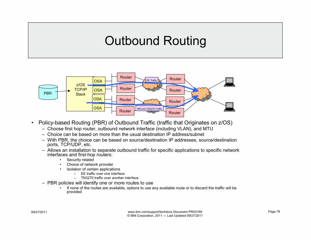
09/27/2011 www.ibm.com/support/techdocs Document PRS3169
© IBM Corporation, 2011 --- Last Updated 09/27/2011
Page 78
z/OS
TCP/IP
Stack
• Policy-based Routing (PBR) of Outbound Traffic (traffic that Originates on z/OS)– Choose first hop router, outbound network interface (including VLAN), and MTU
– Choice can be based on more than the usual destination IP address/subnet
– With PBR, the choice can be based on source/destination IP addresses, source/destination ports, TCP/UDP, etc.
– Allows an installation to separate outbound traffic for specific applications to specific network interfaces and first-hop routers:
• Security related
• Choice of network provider
• Isolation of certain applications– EE traffic over one interface
– TN3270 traffic over another interface
– PBR policies will identify one or more routes to use• If none of the routes are available, options to use any available route or to discard the traffic will be
provided
Outbound Routing
PBR
OSA
OSA
OSA
OSA
Router
Router
Router
Router
Router
Router
Router
Router
EE Traffic
MQ and TN3270 Traffic
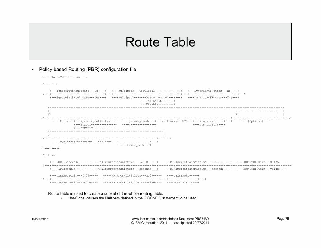
09/27/2011 www.ibm.com/support/techdocs Document PRS3169
© IBM Corporation, 2011 --- Last Updated 09/27/2011
Page 79
• Policy-based Routing (PBR) configuration file
>>---RouteTable---name--->
>---{--->
+---IgnorePathMtuUpdate---No----+ +---Multipath---UseGlobal---------------+ +---DynamicXCFRoutes---No----+
>---+-------------------------------+---+---------------------------------------+---+----------------------------+--->
+---IgnorePathMtuUpdate---Yes---+ +---Multipath---+---PerConnection---+---+ +---DynamicXCFRoutes---Yes---+
+---PerPacket-------+
+---Disable---------+
+---------------------------------------------------------------------------------------------------------------------------------------+
| +----------------------+ |
V V | |
>-----+------------------------------------------------------------------------------------------------------+-----+---------------+---+---+--->
+---Route---+---ipaddr/prefix_len---+---+---gateway_addr---+---intf_name---MTU---+---mtu_size------+---+ +---|Options|---+
+---ipaddr--------------+ +---=--------------+ +---DEFAULTSIZE---+
+---DEFAULT-------------+
+------------------------------------------------------------------+
V |
>-----+-----------------------------------------------------------+---+--->
+---DynamicRoutingParms---inf_name---+------------------+---+
+---gateway_addr---+
>---{---><
Options:
+---NOREPLaceable---+ +---MAXImumretransmittime---120.0-----+ +---MIMImumretransmittime---0.50------+ +---ROUNDTRIPGain---0.125---+
|---+-------------------+---+-------------------------------------+---+-------------------------------------+---+---------------------------+--->
+---REPLaceable-----+ +---MAXImumretransmittime---seconds---+ +---MIMImumretransmittime---seconds---+ +---ROUNDTRIPGain---value---+
+---VARIANCEGain---0.25----+ +---VARIANCEMultiplier---2.00----+ +---DELAYAcks-----+
>---+--------------------------+---+--------------------------------+---+-----------------+---|
+---VARIANCEGain---value---+ +---VARIANCEMultiplier---value---+ +---NODELAYAcks---+
– RouteTable is used to create a subset of the whole routing table.• UseGlobal causes the Multipath defined in the IPCONFIG statement to be used.
Route Table
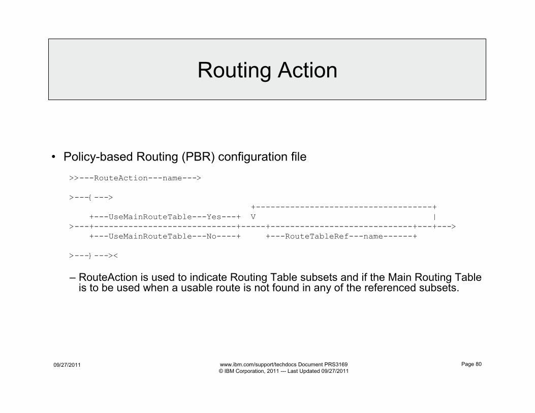
09/27/2011 www.ibm.com/support/techdocs Document PRS3169
© IBM Corporation, 2011 --- Last Updated 09/27/2011
Page 80
• Policy-based Routing (PBR) configuration file
>>---RouteAction---name--->
>---{--->
+------------------------------------+
+---UseMainRouteTable---Yes---+ V |
>---+-----------------------------+-----+-----------------------------+---+--->
+---UseMainRouteTable---No----+ +---RouteTableRef---name------+
>---}---><
– RouteAction is used to indicate Routing Table subsets and if the Main Routing Table is to be used when a usable route is not found in any of the referenced subsets.
Routing Action
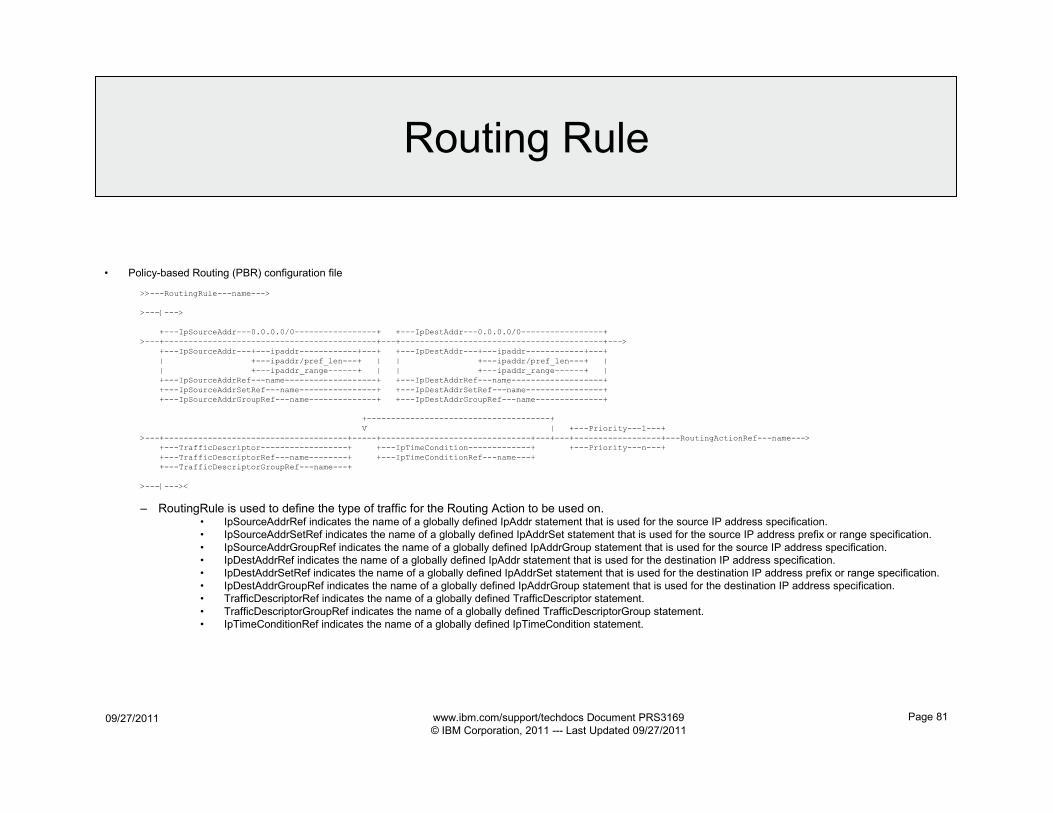
09/27/2011 www.ibm.com/support/techdocs Document PRS3169
© IBM Corporation, 2011 --- Last Updated 09/27/2011
Page 81
• Policy-based Routing (PBR) configuration file
>>---RoutingRule---name--->
>---{--->
+---IpSourceAddr---0.0.0.0/0-----------------+ +---IpDestAddr---0.0.0.0/0-----------------+
>---+--------------------------------------------+---+------------------------------------------+--->
+---IpSourceAddr---+---ipaddr------------+---+ +---IpDestAddr---+---ipaddr------------+---+
| +---ipaddr/pref_len---+ | | +---ipaddr/pref_len---+ |
| +---ipaddr_range------+ | | +---ipaddr_range------+ |
+---IpSourceAddrRef---name-------------------+ +---IpDestAddrRef---name-------------------+
+---IpSourceAddrSetRef---name----------------+ +---IpDestAddrSetRef---name----------------+
+---IpSourceAddrGroupRef---name--------------+ +---IpDestAddrGroupRef---name--------------+
+--------------------------------------+
V | +---Priority---1---+
>---+--------------------------------------+-----+-------------------------------+---+---+------------------+---RoutingActionRef---name--->
+---TrafficDescriptor------------------+ +---IpTimeCondition-------------+ +---Priority---n---+
+---TrafficDescriptorRef---name--------+ +---IpTimeConditionRef---name---+
+---TrafficDescriptorGroupRef---name---+
>---{---><
– RoutingRule is used to define the type of traffic for the Routing Action to be used on.• IpSourceAddrRef indicates the name of a globally defined IpAddr statement that is used for the source IP address specification.
• IpSourceAddrSetRef indicates the name of a globally defined IpAddrSet statement that is used for the source IP address prefix or range specification.
• IpSourceAddrGroupRef indicates the name of a globally defined IpAddrGroup statement that is used for the source IP address specification.
• IpDestAddrRef indicates the name of a globally defined IpAddr statement that is used for the destination IP address specification.
• IpDestAddrSetRef indicates the name of a globally defined IpAddrSet statement that is used for the destination IP address prefix or range specification.
• IpDestAddrGroupRef indicates the name of a globally defined IpAddrGroup statement that is used for the destination IP address specification.
• TrafficDescriptorRef indicates the name of a globally defined TrafficDescriptor statement.
• TrafficDescriptorGroupRef indicates the name of a globally defined TrafficDescriptorGroup statement.
• IpTimeConditionRef indicates the name of a globally defined IpTimeCondition statement.
Routing Rule
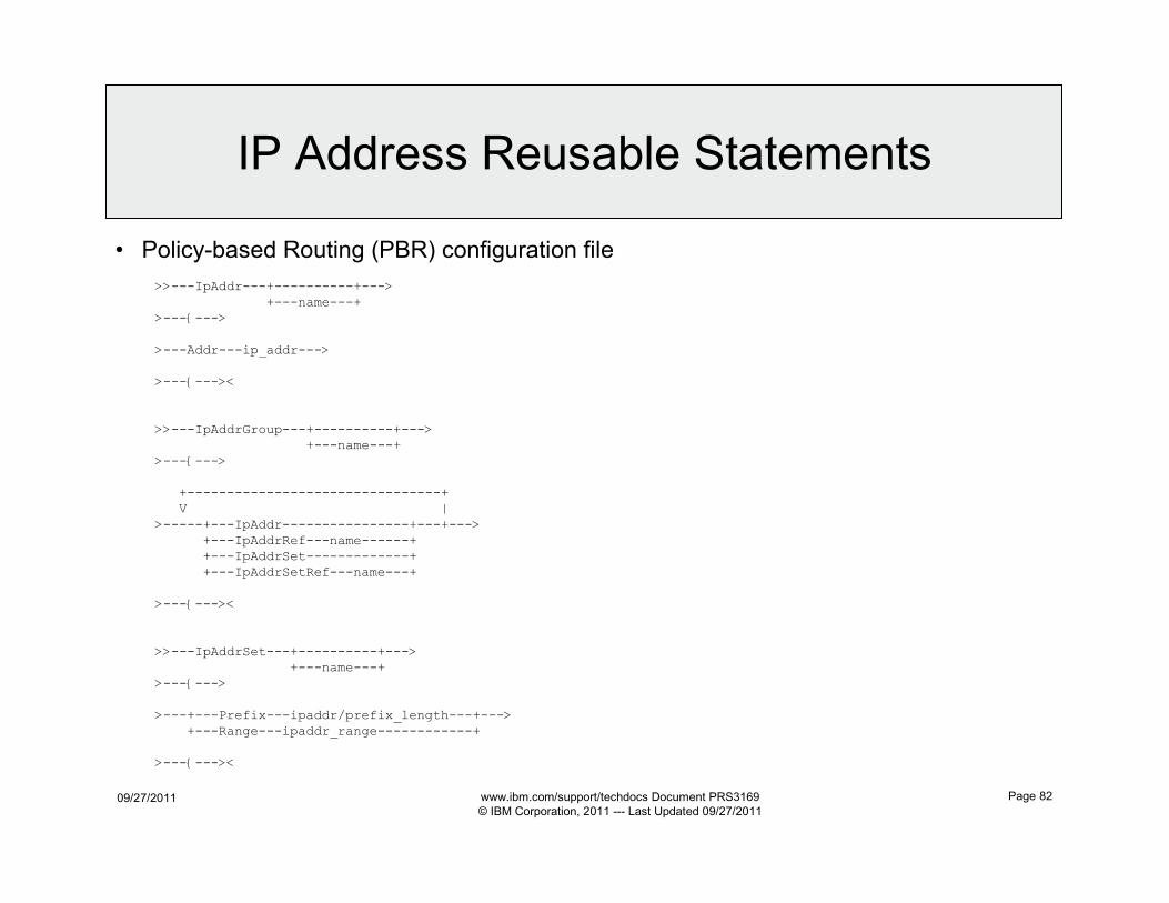
09/27/2011 www.ibm.com/support/techdocs Document PRS3169
© IBM Corporation, 2011 --- Last Updated 09/27/2011
Page 82
• Policy-based Routing (PBR) configuration file
>>---IpAddr---+----------+--->
+---name---+>---{--->
>---Addr---ip_addr--->
>---{---><
>>---IpAddrGroup---+----------+--->+---name---+
>---{--->
+--------------------------------+V |
>-----+---IpAddr----------------+---+--->
+---IpAddrRef---name------++---IpAddrSet-------------+
+---IpAddrSetRef---name---+
>---{---><
>>---IpAddrSet---+----------+--->+---name---+
>---{--->
>---+---Prefix---ipaddr/prefix_length---+--->
+---Range---ipaddr_range------------+
>---{---><
IP Address Reusable Statements
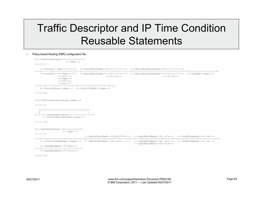
09/27/2011 www.ibm.com/support/techdocs Document PRS3169
© IBM Corporation, 2011 --- Last Updated 09/27/2011
Page 83
• Policy-based Routing (PBR) configuration file
>>---TrafficDescriptor---+----------+--->
+---name---+
>---{--->
+---Protocol---All-----------+ +---SourcePortRange---0---------------+ +---DestinationPortRange---0---------------+
>---+----------------------------+---+-------------------------------------+---+------------------------------------------+---+--------------------+--->
+---Protocol---+---Tcp---+---+ +---SourcePortRange---+---n-------+---+ +---DestinationPortRange---+---n-------+---+ +---Jobname---name---+
+---6-----+ +---n---m---+ +---n---m---+
+---Udp---+
+---17----+
+---All---+
>---+-------------------------+---+--------------------------+--->
+---SecurityZone---name---+ +---SecurityLabel---name---+
>---{---><
>>---TrafficDescriptorGroup---name--->
>---{--->
+----------------------------------------+
V |
>-----+---TrafficDescriptor-------------+---+--->
+---TrafficDescriptorRef---name---+
>---{---><
>>---IpTimeCondition---+----------+--->
+---name---+
>---{--->
+---MonthOfYearMask---111111111111---+ +---DayOfMonthMask---31---1’s---+ +---TimeOfDayRange---0---24---+
>---+--------------------------------+---+------------------------------------+---+-------------------------------+---+-----------------------------+--->
+---ConditionTimeRange---range---+ +---MonthOfYearMask---12---n’s-------+ +---DayOfMonthMask---31---n’s---+ +---TimeOfDayRange---n---m----+
+---DayOfMonthMask---62---n’s---+
+---DayOfWeekMask---1111111---+
>---+-----------------------------+--->
+---DayOfWeekMask---7---n’s---+
>---{---><
Traffic Descriptor and IP Time Condition
Reusable Statements

09/27/2011 www.ibm.com/support/techdocs Document PRS3169
© IBM Corporation, 2011 --- Last Updated 09/27/2011
Page 84
OSA-Express Network
Traffic Analyzer
(OSAENTA)
z/OS
Communications
Server:
IP Diagnosis
Guide
GC31-8782
09/27/2011 www.ibm.com/support/techdocs Document PRS3169
© IBM Corporation, 2011 --- Last Updated 09/27/2011
Page 85
OSAENTA Overview
• OSA-Express network traffic analyzer (OSAENTA) traces frames for an OSA in QDIO mode.
– New in z/OS V1.8
• OSAENTA is controlled and formatted by z/OS Communications Server (CS), but is collected in the OSA port.
• OSAENTA has capabilities beyond other z/OS CS tracing:
– Trace frames discarded by the OSA.
– Trace the MAC headers for packets.
– Trace ARP packets
– Trace packets to and from other users sharing the OSA (other TCP/IP stacks, z/Linux users, and z/VM users)
• Tracing of other operating systems, other than the local one where OSAENTA is started, requires enablement via HMC (Hardware Management Console).
– Trace SNA packets
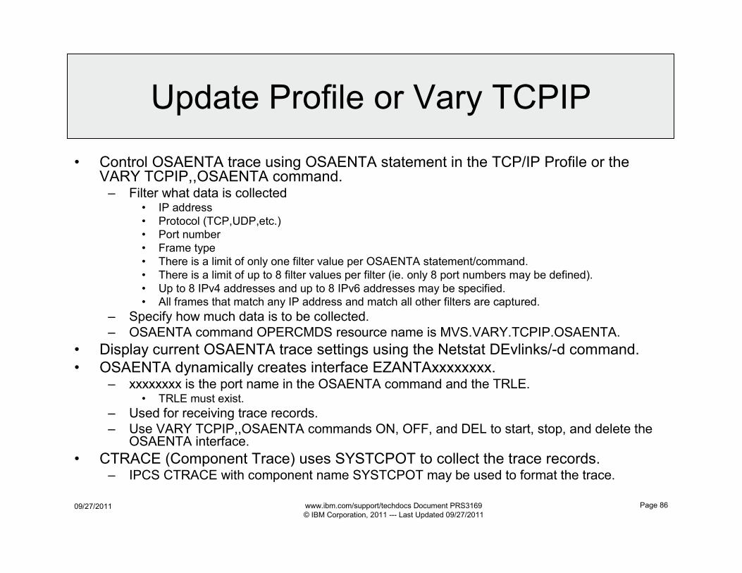
09/27/2011 www.ibm.com/support/techdocs Document PRS3169
© IBM Corporation, 2011 --- Last Updated 09/27/2011
Page 86
Update Profile or Vary TCPIP
• Control OSAENTA trace using OSAENTA statement in the TCP/IP Profile or the VARY TCPIP,,OSAENTA command.– Filter what data is collected
• IP address
• Protocol (TCP,UDP,etc.)
• Port number
• Frame type
• There is a limit of only one filter value per OSAENTA statement/command.
• There is a limit of up to 8 filter values per filter (ie. only 8 port numbers may be defined).
• Up to 8 IPv4 addresses and up to 8 IPv6 addresses may be specified.
• All frames that match any IP address and match all other filters are captured.
– Specify how much data is to be collected.
– OSAENTA command OPERCMDS resource name is MVS.VARY.TCPIP.OSAENTA.
• Display current OSAENTA trace settings using the Netstat DEvlinks/-d command.
• OSAENTA dynamically creates interface EZANTAxxxxxxxx.– xxxxxxxx is the port name in the OSAENTA command and the TRLE.
• TRLE must exist.
– Used for receiving trace records.
– Use VARY TCPIP,,OSAENTA commands ON, OFF, and DEL to start, stop, and delete the OSAENTA interface.
• CTRACE (Component Trace) uses SYSTCPOT to collect the trace records.– IPCS CTRACE with component name SYSTCPOT may be used to format the trace.
09/27/2011 www.ibm.com/support/techdocs Document PRS3169
© IBM Corporation, 2011 --- Last Updated 09/27/2011
Page 87
Synchronization of OSA
Diagnostic Data
(QDIOSYNC)
z/OS
Communications
Server:
SNA Diagnosis
Volume 1,
Techniques
and Procedures
GC31-6850
z/OS
Communications
Server:
SNA Operation
SC31-8779
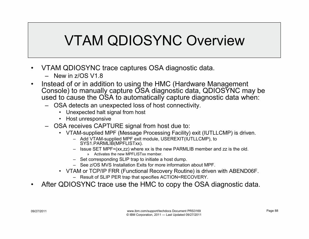
09/27/2011 www.ibm.com/support/techdocs Document PRS3169
© IBM Corporation, 2011 --- Last Updated 09/27/2011
Page 88
VTAM QDIOSYNC Overview
• VTAM QDIOSYNC trace captures OSA diagnostic data.– New in z/OS V1.8
• Instead of or in addition to using the HMC (Hardware Management Console) to manually capture OSA diagnostic data, QDIOSYNC may be used to cause the OSA to automatically capture diagnostic data when:– OSA detects an unexpected loss of host connectivity.
• Unexpected halt signal from host
• Host unresponsive
– OSA receives CAPTURE signal from host due to:• VTAM-supplied MPF (Message Processing Facility) exit (IUTLLCMP) is driven.
– Add VTAM-supplied MPF exit module, USEREXIT(IUTLLCMP), to SYS1.PARMLIB(MPFLISTxx).
– Issue SET MPF=(xx,zz) where xx is the new PARMLIB member and zz is the old.» Activates the new MPFLISTxx member.
– Set corresponding SLIP trap to initiate a host dump.
– See z/OS MVS Installation Exits for more information about MPF.
• VTAM or TCP/IP FRR (Functional Recovery Routine) is driven with ABEND06F.– Result of SLIP PER trap that specifies ACTION=RECOVERY.
• After QDIOSYNC trace use the HMC to copy the OSA diagnostic data.
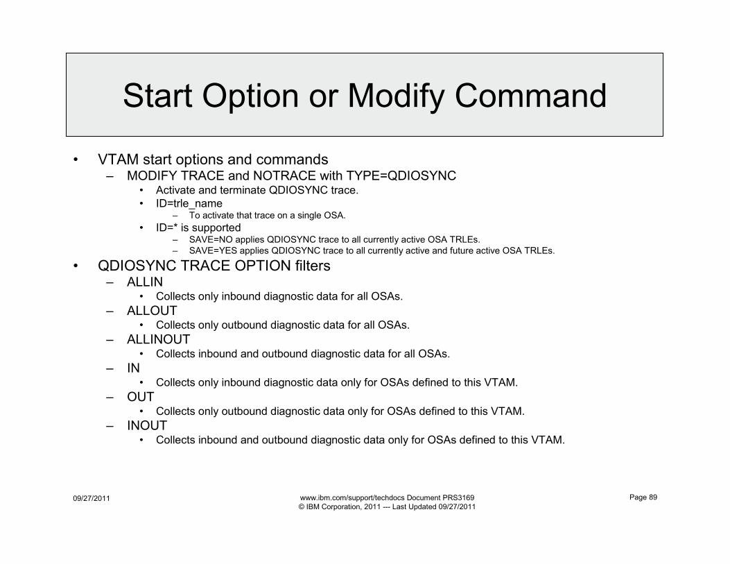
09/27/2011 www.ibm.com/support/techdocs Document PRS3169
© IBM Corporation, 2011 --- Last Updated 09/27/2011
Page 89
Start Option or Modify Command
• VTAM start options and commands– MODIFY TRACE and NOTRACE with TYPE=QDIOSYNC
• Activate and terminate QDIOSYNC trace.
• ID=trle_name– To activate that trace on a single OSA.
• ID=* is supported– SAVE=NO applies QDIOSYNC trace to all currently active OSA TRLEs.
– SAVE=YES applies QDIOSYNC trace to all currently active and future active OSA TRLEs.
• QDIOSYNC TRACE OPTION filters– ALLIN
• Collects only inbound diagnostic data for all OSAs.
– ALLOUT• Collects only outbound diagnostic data for all OSAs.
– ALLINOUT• Collects inbound and outbound diagnostic data for all OSAs.
– IN• Collects only inbound diagnostic data only for OSAs defined to this VTAM.
– OUT• Collects only outbound diagnostic data only for OSAs defined to this VTAM.
– INOUT• Collects inbound and outbound diagnostic data only for OSAs defined to this VTAM.
09/27/2011 www.ibm.com/support/techdocs Document PRS3169
© IBM Corporation, 2011 --- Last Updated 09/27/2011
Page 90
OSA Segmentation Offload
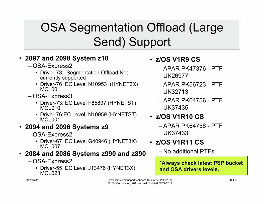
09/27/2011 www.ibm.com/support/techdocs Document PRS3169
© IBM Corporation, 2011 --- Last Updated 09/27/2011
Page 91
• 2097 and 2098 System z10–OSA-Express2
• Driver-73: Segmentation Offload Not currently supported
• Driver-76 EC Level N10953 (HYNET3X) MCL001
–OSA-Express3• Driver-73: EC Level F85897 (HYNETST) MCL010
• Driver-76:EC Level N10959 (HYNETST) MCL001
• 2094 and 2096 Systems z9–OSA-Express2
• Driver-67 EC Level G40946 (HYNET3X) MCL007
• 2084 and 2086 Systems z990 and z890–OSA-Express2
• Driver-55 EC Level J13476 (HYNET3X) MCL023
• z/OS V1R9 CS
– APAR PK47376 - PTF
UK26977
– APAR PK56723 - PTF
UK32713
– APAR PK64756 - PTF
UK37435
• z/OS V1R10 CS
– APAR PK64756 - PTF
UK37433
• z/OS V1R11 CS
– No additional PTFs
OSA Segmentation Offload (Large
Send) Support
*Always check latest PSP bucket
and OSA drivers levels.
09/27/2011 www.ibm.com/support/techdocs Document PRS3169
© IBM Corporation, 2011 --- Last Updated 09/27/2011
Page 92
Commands
z/OS
Communications
Server:
IP System
Administrator’s
Commands
SC31-8781
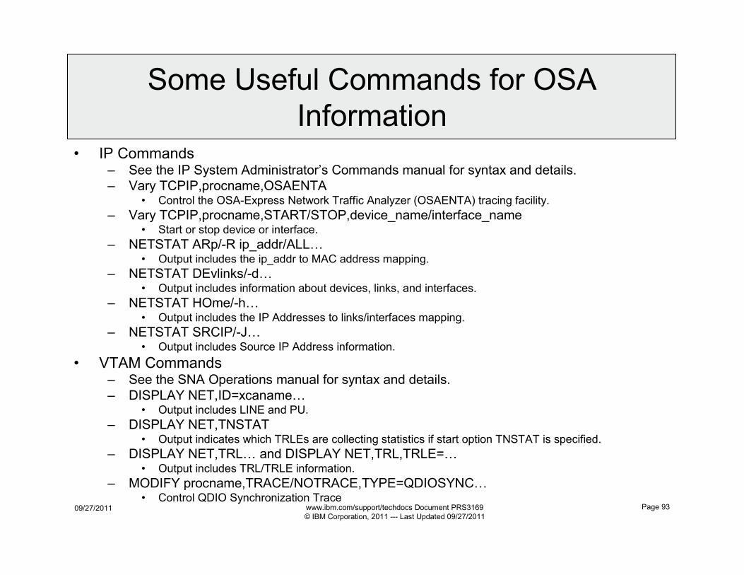
09/27/2011 www.ibm.com/support/techdocs Document PRS3169
© IBM Corporation, 2011 --- Last Updated 09/27/2011
Page 93
Some Useful Commands for OSA
Information• IP Commands
– See the IP System Administrator’s Commands manual for syntax and details.
– Vary TCPIP,procname,OSAENTA• Control the OSA-Express Network Traffic Analyzer (OSAENTA) tracing facility.
– Vary TCPIP,procname,START/STOP,device_name/interface_name• Start or stop device or interface.
– NETSTAT ARp/-R ip_addr/ALL…• Output includes the ip_addr to MAC address mapping.
– NETSTAT DEvlinks/-d…• Output includes information about devices, links, and interfaces.
– NETSTAT HOme/-h…• Output includes the IP Addresses to links/interfaces mapping.
– NETSTAT SRCIP/-J…• Output includes Source IP Address information.
• VTAM Commands– See the SNA Operations manual for syntax and details.
– DISPLAY NET,ID=xcaname…• Output includes LINE and PU.
– DISPLAY NET,TNSTAT• Output indicates which TRLEs are collecting statistics if start option TNSTAT is specified.
– DISPLAY NET,TRL… and DISPLAY NET,TRL,TRLE=…• Output includes TRL/TRLE information.
– MODIFY procname,TRACE/NOTRACE,TYPE=QDIOSYNC…• Control QDIO Synchronization Trace

09/27/2011 www.ibm.com/support/techdocs Document PRS3169
© IBM Corporation, 2011 --- Last Updated 09/27/2011
Page 94
More Information
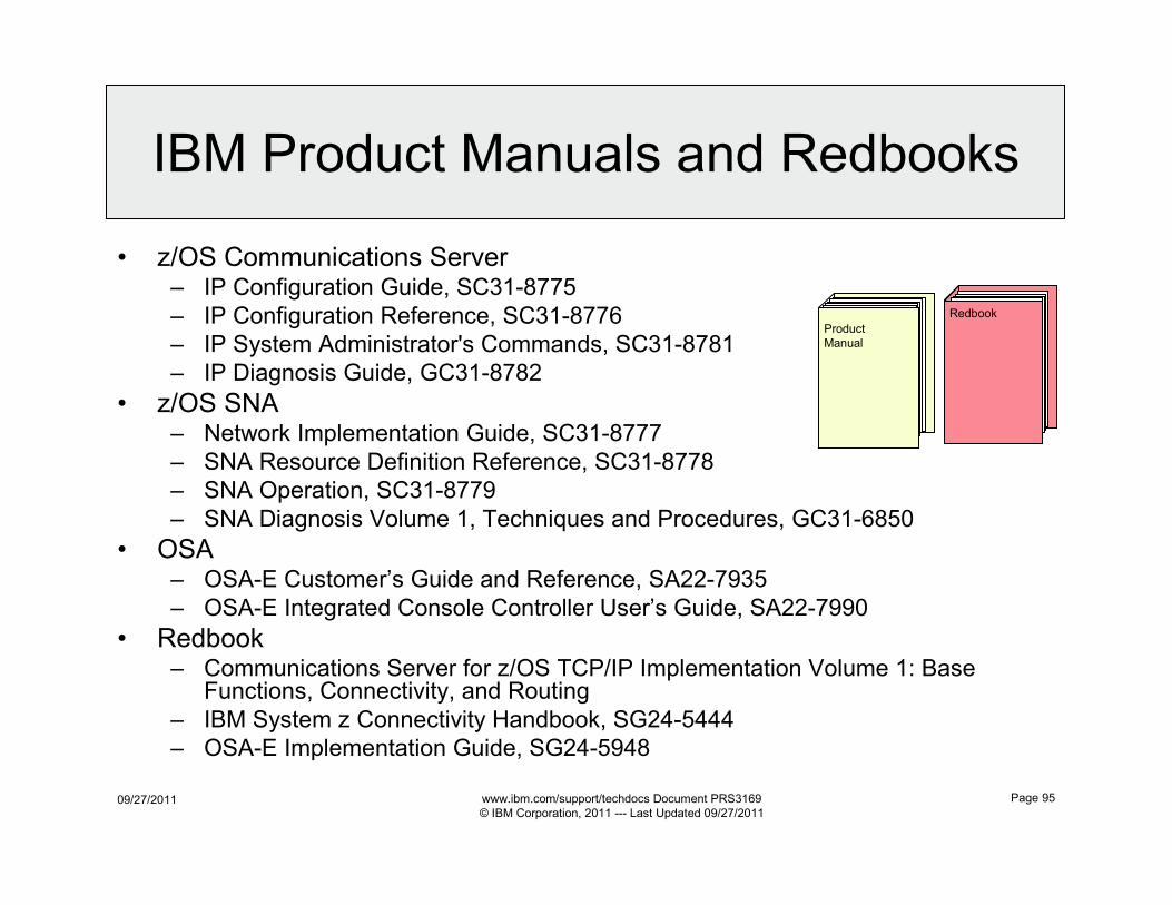
09/27/2011 www.ibm.com/support/techdocs Document PRS3169
© IBM Corporation, 2011 --- Last Updated 09/27/2011
Page 95
IBM Product Manuals and Redbooks
• z/OS Communications Server– IP Configuration Guide, SC31-8775
– IP Configuration Reference, SC31-8776
– IP System Administrator's Commands, SC31-8781
– IP Diagnosis Guide, GC31-8782
• z/OS SNA– Network Implementation Guide, SC31-8777
– SNA Resource Definition Reference, SC31-8778
– SNA Operation, SC31-8779
– SNA Diagnosis Volume 1, Techniques and Procedures, GC31-6850
• OSA– OSA-E Customer’s Guide and Reference, SA22-7935
– OSA-E Integrated Console Controller User’s Guide, SA22-7990
• Redbook– Communications Server for z/OS TCP/IP Implementation Volume 1: Base
Functions, Connectivity, and Routing
– IBM System z Connectivity Handbook, SG24-5444
– OSA-E Implementation Guide, SG24-5948
Redbook
Product
Manual
09/27/2011 www.ibm.com/support/techdocs Document PRS3169
© IBM Corporation, 2011 --- Last Updated 09/27/2011
Page 96
Web Information
• IBM ATS Technical Documents:– http://www.ibm.com/support/techdocs
• z/OS Communications Server– http://www.ibm.com/software/network/commserver/zos
• IBM Information Center– http://www.ibm.com/support/documentation/us/en
• IBM Education Assistant– http://www.ibm.com/software/info/education/assistant
• z/OS Communications Server Publications– http://www.ibm.com/systems/z/os/zos/bkserv
• IBM Redbooks– http://www.redbooks.ibm.com
• System z main web site:– http://www.ibm.com/systems/z/hardware/

09/27/2011 www.ibm.com/support/techdocs Document PRS3169
© IBM Corporation, 2011 --- Last Updated 09/27/2011
Page 97
The End

09/27/2011 www.ibm.com/support/techdocs Document PRS3169
© IBM Corporation, 2011 --- Last Updated 09/27/2011
Page 98
The End