Zoom ZFX Plug-In
156
Operation Manual ©ZOOM Corporation Reproduction of this manual, in whole or in part, by any means, is prohibited. ZFX STACK PACKAGE / ZFX CONTROL PACKAGE ZFX Plug-in
-
Upload
denis-martini -
Category
Documents
-
view
55 -
download
0
Transcript of Zoom ZFX Plug-In
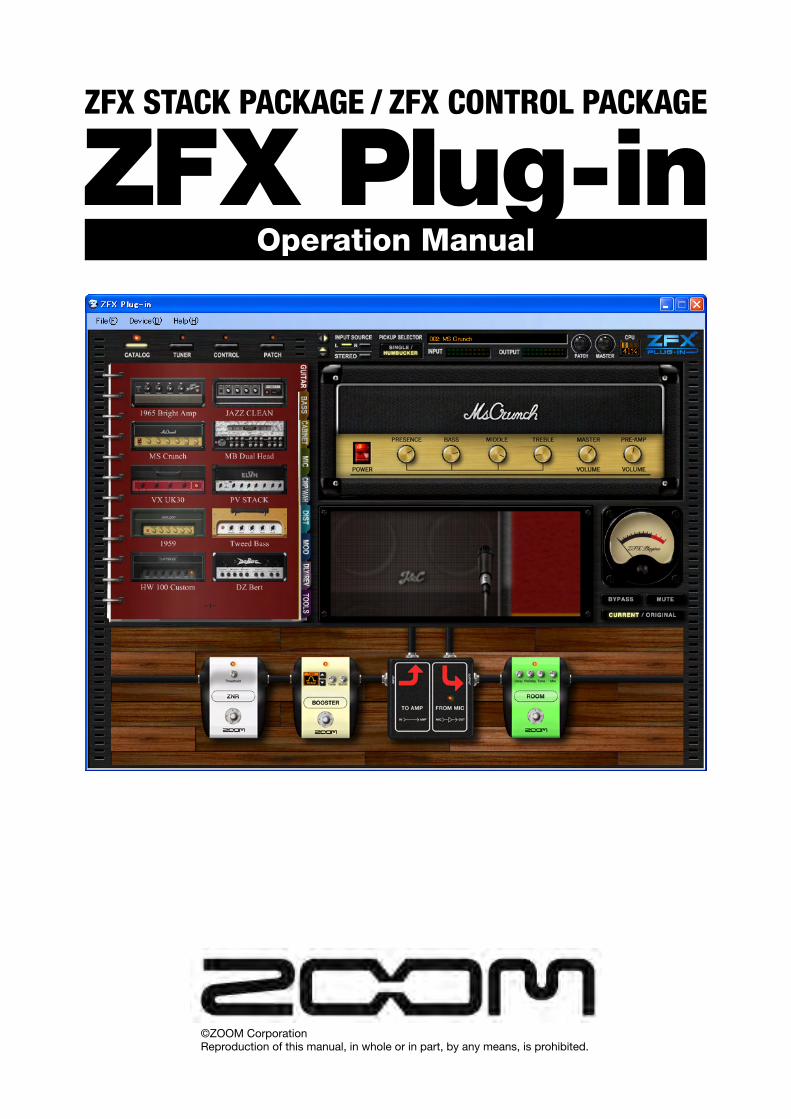
Operation Manual
©ZOOM CorporationReproduction of this manual, in whole or in part, by any means, is prohibited.
ZFX STACK PACKAGE / ZFX CONTROL PACKAGE
ZFX Plug-in
001
SAFETY PRECAUTIONS Usage Precautions
Software License
Zoom Corporation grants the right to use the ZFX Plug-in, provided that you agree with all conditions listed below.Using the software is considered acceptance of these conditions.
● Zoom Corporation holds the copyright to the software and the accompanying documentation, and all associated rights. All rights revert to Zoom Corporation.
● Unauthorized redistribution, sale, leasing, renting, alteration, or reverse engineering of the software is prohibited.
● The software may not be used for purposes that infringe on the copyright of third parties. Zoom Corporation does not bear liability for cases where the software is used for any such purpose.
● Zoom Corporation does not bear liability for any damages or claims from third parties arising from the use of the software, whether directly or indirectly. If the contents of a hard disk are lost due to use of the software, Zoom Corporation does not accept any claims for restoring or preserving such contents.
● Features and specifications of the software and the contents of the documentation may be changed in future without notice.
※Microsoft, Windows XP, and Windows Vista are registered trademarks of Microsoft Corporation in the U.S.A. and in other countries.※Intel and Pentium are the registered trademark of Intel Corporation.※AMD and Athlon are the registered trademark of Advanced Micro Devices Inc.※VST PlugIn Interface Technology by Steinberg Media Technologies GmbH.※Steinberg, Cubase and VST are registered trademarks of Steinberg Media Technologies GmbH.※Adobe and Adobe Acrobat are registered trademarks of Adobe Systems Incorporated.※MIDI is registered trademark of Association of Musical Electronics Industry (AMEI).※All other trademarks, product names, and company names mentioned in this document are the property of their respective owners.※All trademarks and registered trademarks mentioned in this manual are for identification purposes only and are not intended to infringe on the
copyrighted properties of their respective owners.

002
Contents
Introduction……………………………………………………………………………………………………… Features of USB Audio Interface S2t / USB Audio Interface C5.1t……………………………
Features of ZFX Plug-in… ……………………………………………………………………………
Controls and Functions of ZFX Plug-in…………………………………………………………………Quick Guide………………………………………………………………………………………………………… …… Starting up………………………………………………………………………………………………
Selecting input source ……………………………………………………………………………
Selecting patches …………………………………………………………………………………
Controlling Amplifiers ……………………………………………………………………………
Magnifying and scrolling the Effect Area… ………………………………………………………
Controlling Effectors…………………………………………………………………………………
Selecting Instruments… ……………………………………………………………………………
Storing patches………………………………………………………………………………………
Signal Control Area……………………………………………………………………………………………… Controls and Functions… …………………………………………………………………………
Selecting input source………………………………………………………………………………
Selecting pickups……………………………………………………………………………………
Showing/Hiding frames… ……………………………………………………………………………
Adjusting patch level… ……………………………………………………………………………
Adjusting master level………………………………………………………………………………
About the connection state…………………………………………………………………………
Basic Operation……………………………………………………………………………………………………Catalog…… …………………………………………………………………………………………………………… Starting up the Catalog… …………………………………………………………………………
Catalog - Basic operation… ………………………………………………………………………
Turning pages… …………………………………………………………………………
Turning a number of pages………………………………………………………………
Jumping pages by index…………………………………………………………………
Jumping to detail page………………………………………………………………………………
Selecting Instruments from detail page………………………………………………………………
Amplifying Area……………………………………………………………………………………………………… Controls and Functions… …………………………………………………………………………
Amplifier Section - Basic operation… ……………………………………………………………
Setting Amplifiers…………………………………………………………………………
Adjusting Amplifiers………………………………………………………………………
Deleting Amplifiers… ……………………………………………………………………
Booth Section - Basic operation… ………………………………………………………………
Setting Cabinets and Microphones……………………………………………………
Deleting Cabinets and Microphones…………………………………………………
Replacing Microphones…………………………………………………………………
Adjusting the microphone distance……………………………………………………
Adjusting the microphone position… …………………………………………………
Contents005005006007008008009009010011012013015018018019019020021021022023024024025025026027028029031031031031033033034034035036036037

003
Contents
Effect Area ……………………………………………………………………………………………………… Controls and Functions… …………………………………………………………………………
Signal flow of Effect Area……………………………………………………………………………
Selecting/Adjusting instruments……………………………………………………………………
Setting instruments………………………………………………………………………
Positioning instruments…………………………………………………………………
Adjusting instruments……………………………………………………………………
Deleting instruments… …………………………………………………………………
Magnifying and Scrolling……………………………………………………………………………
Magnifying the Effect Area………………………………………………………………
Zooming up the instrument… …………………………………………………………
Zoom to next instrument………………………………………………………………
Scrolling the Effect Area…………………………………………………………………
Wiring shields…………………………………………………………………………………………
Connecting a shield………………………………………………………………………
Changing the shield connection… ……………………………………………………
Connecting directly to input / output… ………………………………………………
Deleting shields… ………………………………………………………………………
Splitters and Mixers…………………………………………………………………………………
Operating Splitters… ……………………………………………………………………
Operating Mixers…………………………………………………………………………
Amplifier Module… …………………………………………………………………………………
Operating Multiple Amplifier Modules…………………………………………………
Deleting Amplifier Modules……………………………………………………………
Patch Management……………………………………………………………………………………………… Starting up the Patch Manager… …………………………………………………………………
Operating patches……………………………………………………………………………………
Selecting patches………………………………………………………………………
Storing patches… ………………………………………………………………………
Storing to certain destination……………………………………………………………
Ordering patches……………………………………………………………………………
Renaming patches… ……………………………………………………………………
Deleting patches…………………………………………………………………………
Clearing the current setting… …………………………………………………………
Exporting current setting… ……………………………………………………………
Importing current setting………………………………………………………………
Operating banks… …………………………………………………………………………………
Creating a bank… ………………………………………………………………………
Ordering banks………………………………………………………………………………
Renaming banks…………………………………………………………………………
Deleting banks……………………………………………………………………………
Exporting banks… ………………………………………………………………………
Importing banks… ………………………………………………………………………
Bypassing Area……………………………………………………………………………………………………… Controls and Functions… …………………………………………………………………………
Bypassing the sound… ……………………………………………………………………………
038038038039039040041041042042043044044045045046047048049049050053053054055055056056058059062064065066067068069069070071072074075077077077
004
Contents
Muting the sound……………………………………………………………………………………
Comparing current and original state… …………………………………………………………
Tuner … ……………………………………………………………………………………………………………… Starting up the tuner…………………………………………………………………………………
Using the chromatic tuner… ………………………………………………………………………
Adjusting the calibration……………………………………………………………………………
Dropping halftone……………………………………………………………………………………
Dropping whole tone… ……………………………………………………………………………
Using other tuner types… ……………………………………………………………………………
Expression pedal and foot switches… ………………………………………………………………… Starting up the Pedal/Switch Manager……………………………………………………………
… … The Pedal/Switch Manager with the C5.1t connection………………………………
The Pedal/Switch Manager with the S2t connection…………………………………
Assigning parameters… ………………………………………………………………………………
Assigning parameters to expression pedal……………………………………………
Assigning parameters to foot switches… ……………………………………………
Adjusting the parameter range……………………………………………………………
Deleting the assignment…………………………………………………………………
Assigning Global Settings… ………………………………………………………………………
Assigning next/previous patch selection…………………………………………………
Assigning next/previous bank selection… ……………………………………………
Assigning the patch selection… ………………………………………………………
Assigning the bypass/mute function… ………………………………………………
Enabling the Global Setting… …………………………………………………………
Canceling the assignment………………………………………………………………
Operating the machine image………………………………………………………………………
Checking pedal assignments……………………………………………………………
Checking foot switch assignments… …………………………………………………
Switching USB Audio Interface S2t/USB Audio Interface C5.1t……………………
Other functions………………………………………………………………………………………
Targeting the instance……………………………………………………………………
Receiving MIDI message… ……………………………………………………………
Adjusting pedal calibration………………………………………………………………
Standalone mode… ………………………………………………………………………………………………… Starting up the host application……………………………………………………………………
Device Menu…………………………………………………………………………………………
Selecting ASIO driver……………………………………………………………………
Configuring ASIO driver…………………………………………………………………
Connect/Disconnect… …………………………………………………………………
File Menu… …………………………………………………………………………………………
Setting BPM………………………………………………………………………………
Quitting application………………………………………………………………………
Help Menu……………………………………………………………………………………………
Displaying the current version… ………………………………………………………
Troubleshooting……………………………………………………………………………………………………Appendix…
078078079079080082082082083085085085086087087089090092093093095097100102102103103104106106106107108112112113113113114114114115115115117

005
Introduction . Features of ZFX Plug-in
The USB Audio Interface S2t / USB Audio Interface C5.1t (simply called the “S2t”, “C5.1t” in this manual) are the USB audio interface with following features.● Real time control with the expression pedal
The C5.1t has a built-in expression pedal unit as standard, and for the S2t, the external pedals (FP01/FP02) are available optionally. With these expression pedals, you can adjust the effect tone or volume in real time.
● Tube powered AcceleratorThe analog input stage features an Accelerator that lets you freely mix the signals amplified by a vacuum tube circuit and a solid-state circuit. In this way, you can add characteristics tube compression and distortion to a clean sound.
● Programmable function foot switchesThe C5.1t has five built-in foot switches, and for the S2t, the external foot switch(FS01) is available optionally. With these switches, you can program the functions such as switching amp channels, setting delay time, switching patches, and various other tasks.
● Support for a wide range of input sourcesInput connectors are compatible with high-impedance sources and 48V phantom power. These allow the unit to handle any kind of source, from electric guitar/bass and other high-impedance instruments to dynamic/condenser microphones, synthesizers and other line-level equipment.
● Software copy protectionS2t/C5.1t works as a hardware key to prevent copies. Please make sure that S2t/C5.1t is connected to your computer before starting up ZFX Plug-in. ZFX Plug-in works only when S2t/C5.1t is connected properly.
Thank you for selecting the ZFX Stack Package/ZFX Control Package. This manual covers both the ZFX Stack Package and the ZFX Control Package. In order to take full advantage of the their versatile functions and to ensure trouble-free enjoyment, please read this manual carefully. Keep this manual in a safe place together with the warranty card.
Introduction
Features of USB Audio Interface S2t / USB Audio Interface C5.1t

006
Introduction . Features of ZFX Plug-in
The ZFX Plug-in is a VST plug-in effect with the following features.● Ready-to-use patches
Effect module combinations and settings can be stored and recalled as “Patches”. The ZFX Plug-in offers more than 300 ready-to-use patches, and you can store them as many as you want as far as your hard disk drive has enough space.
● The stimulating CatalogZFX Plug-in offers you 78 effects, including amplifiers, effectors and microphones, through a catalog style console. Here, you can choose the instruments much easily and inspirationally while sound making.
● Realistic amplifier/stomp box modeling The analog clip of the tubes and the diodes are simulated digitally, therefore, the distortion characters of tube amplifiers and vintage effectors are precisely modeled. This includes historical and fascinating models and recent popular models. The cabinet simulator brings you the natural reverberation, through the various microphones of variable position.
● Freely editable effect chainThe connections of effectors and amplifiers can be easily changed, by rewiring the shielded cables by mouse. You can freely position them, since there are no limits according to its category, such as drives, modulations, and reverbs, as in usual multiple effectors and plug-in effects.The number of amplifier/effector that can be used at the same time depends on your computer environment.
● Built-in tuner supports special tuning requirementsIn addition to the standard auto-chromatic tuner, various other tuning methods are possible.
Features of ZFX Plug-in
Please take time to read this manual carefully, in order to get the most out of your Z Stack Package/Z Control Package and to ensure optimum performance and reliability.
007
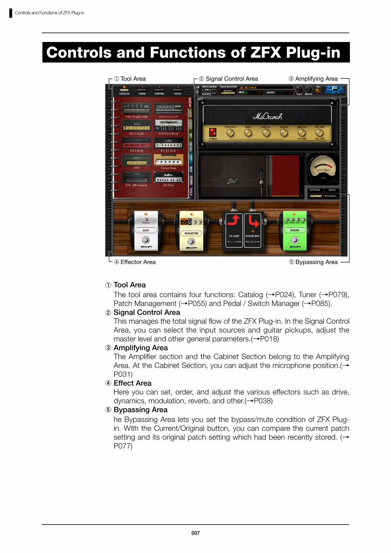
Controls and Functions of ZFX Plug-in
Controls and Functions of ZFX Plug-in
①Tool AreaThe tool area contains four functions: Catalog (→P024), Tuner (→P079), Patch Management (→P055) and Pedal / Switch Manager (→P085).
②Signal Control AreaThis manages the total signal flow of the ZFX Plug-in. In the Signal Control Area, you can select the input sources and guitar pickups, adjust the master level and other general parameters.(→P018)
③Amplifying AreaThe Amplifier section and the Cabinet Section belong to the Amplifying Area. At the Cabinet Section, you can adjust the microphone position.(→P031)
④Effect AreaHere you can set, order, and adjust the various effectors such as drive, dynamics, modulation, reverb, and other.(→P038)
⑤Bypassing Areahe Bypassing Area lets you set the bypass/mute condition of ZFX Plug-in. With the Current/Original button, you can compare the current patch setting and its original patch setting which had been recently stored. (→P077)
⑤ Bypassing Area
③ Amplifying Area ① Tool Area ②…Signal Control Area
④ Effector Area

008
Quick Guide
The application shortcut is located at [Start]-[Programs]-[ZOOM]-[ZFX Plug-in]-[ZFX Plug-in].
Starting up
To start up from a DAW application as a plug-in, please refer the operation manual of your DAW application.
Quick Guide
To start up the ZFX Plug-in by standalone, select ”ZFX Plug-in” as above.

009
Quick Guide
At first, select the input source according to the input of S2t/C5.1t, which your instrument is connected.When guitar/bass is connected to the Hi-Z input, this setting will be ignored. For details, refer “Selecting input source” (→P009)
Selecting input source
Click the [PATCH] button above the Tool Area.1.
Selecting patches
The corresponding LED lights on, and the Patch manager comes available.

010
Quick Guide
Click a patch to load, from the PATCH SELECT list.2.
The patch will be loaded.
To view all patches, drag the scroll bar horizontally.
Drag the knob of the amplifier vertically.1.
Controlling Amplifiers
The effect parameter will be adjusted according to the knob position.
At the Amplifying Area, you can adjust the knob, switches, microphone position, and other parameters of the amplifier, which are currently selected.
011
Quick Guide
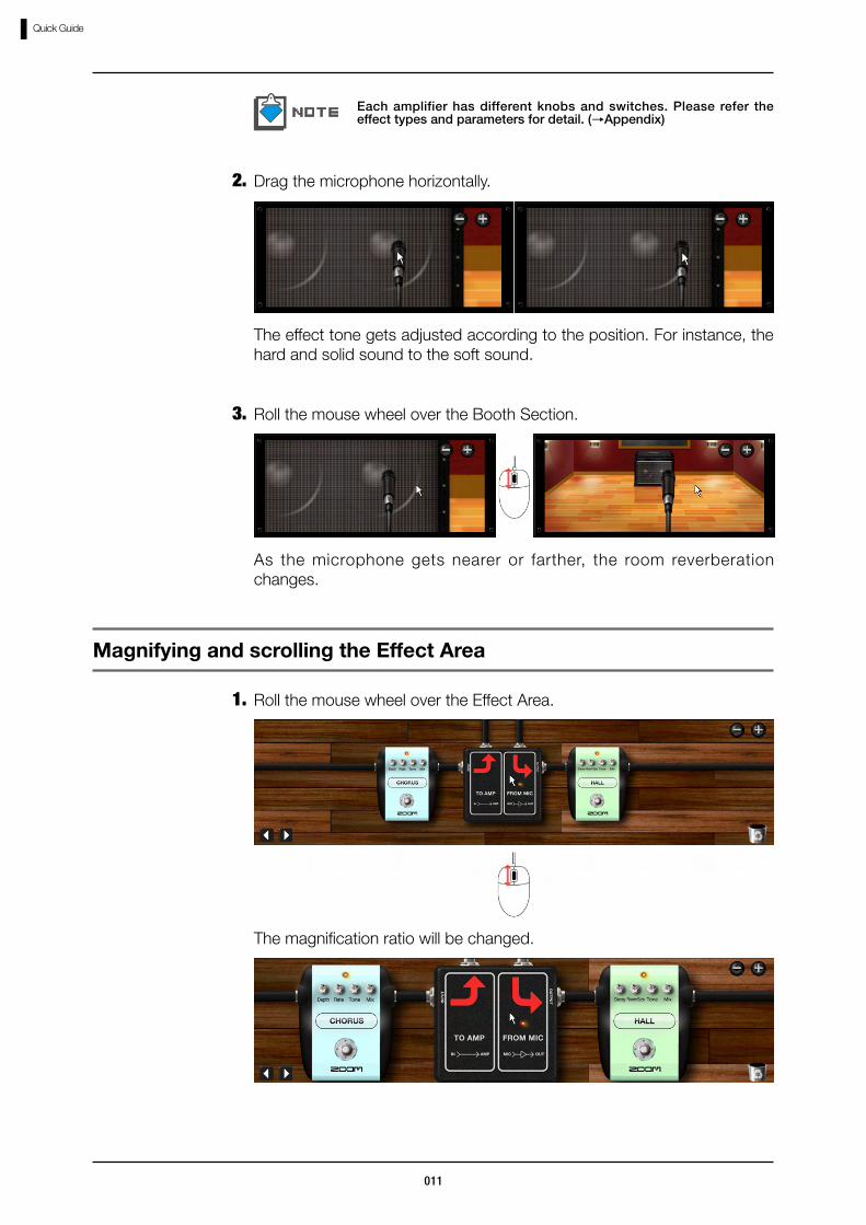
Drag the microphone horizontally.2.
Each amplifier has different knobs and switches. Please refer the effect types and parameters for detail. (→Appendix)
Roll the mouse wheel over the Booth Section.3.
As the microphone gets nearer or farther, the room reverberation changes.
The effect tone gets adjusted according to the position. For instance, the hard and solid sound to the soft sound.
Roll the mouse wheel over the Effect Area.1.
Magnifying and scrolling the Effect Area
The magnification ratio will be changed.
012
Quick Guide
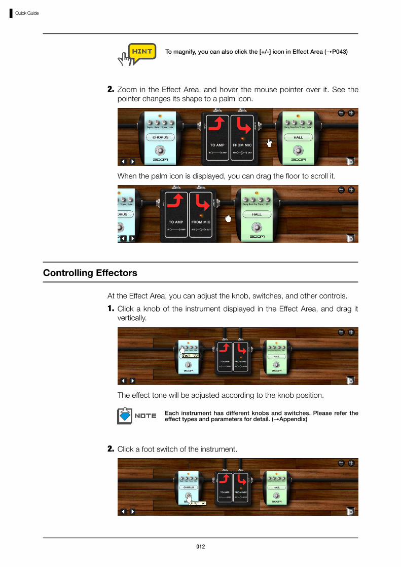
Click a knob of the instrument displayed in the Effect Area, and drag it vertically.
1.
Controlling Effectors
The effect tone will be adjusted according to the knob position.
At the Effect Area, you can adjust the knob, switches, and other controls.
Each instrument has different knobs and switches. Please refer the effect types and parameters for detail. (→Appendix)
Click a foot switch of the instrument.2.
To magnify, you can also click the [+/-] icon in Effect Area (→P043)
Zoom in the Effect Area, and hover the mouse pointer over it. See the pointer changes its shape to a palm icon.
2.
When the palm icon is displayed, you can drag the floor to scroll it.

013
Quick Guide
The instrument will be powered off, and bypassed. To enable it again, click the foot switch once more.
Click the [CATALOG] button above the Tool Area.1.
Selecting Instruments
The corresponding LED lights on, and the Catalog comes available.
Click the index labeled as “GUITAR”, “BASS”, “CABINET” and other, at the right side of the Catalog.
2.
Instruments can also be turned off by clicking its LED.
014
Quick Guide
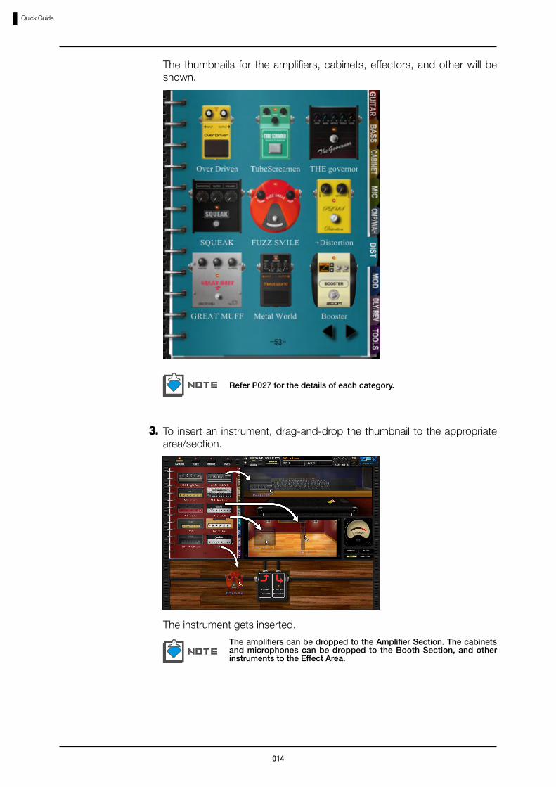
The thumbnails for the amplifiers, cabinets, effectors, and other will be shown.
Refer P027 for the details of each category.
To insert an instrument, drag-and-drop the thumbnail to the appropriate area/section.
3.
The amplifiers can be dropped to the Amplifier Section. The cabinets and microphones can be dropped to the Booth Section, and other instruments to the Effect Area.
The instrument gets inserted.

015
Quick Guide
The amplifiers, cabinets, and microphones can be deleted the same way. At the Effect Area, the [TRASH CAN] icon is also available.
To delete the instrument, double-click the right button over it.4.
The instrument gets deleted.
Click the [PATCH] button above the Tool Area.1.
Storing patches
To store the patch setting, follow the instruction below.
The corresponding LED lights on, and the Patch Manager comes available.
016
Quick Guide
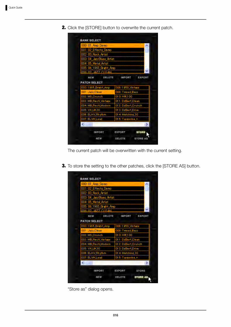
Click the [STORE] button to overwrite the current patch.2.
The current patch will be overwritten with the current setting.
To store the setting to the other patches, click the [STORE AS] button.3.
“Store as” dialog opens.
017
Quick Guide
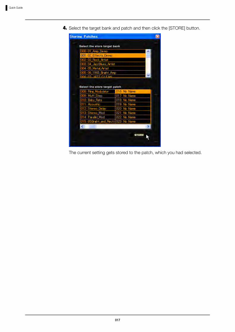
Select the target bank and patch and then click the [STORE] button.4.
The current setting gets stored to the patch, which you had selected.
018
Signal Control Area
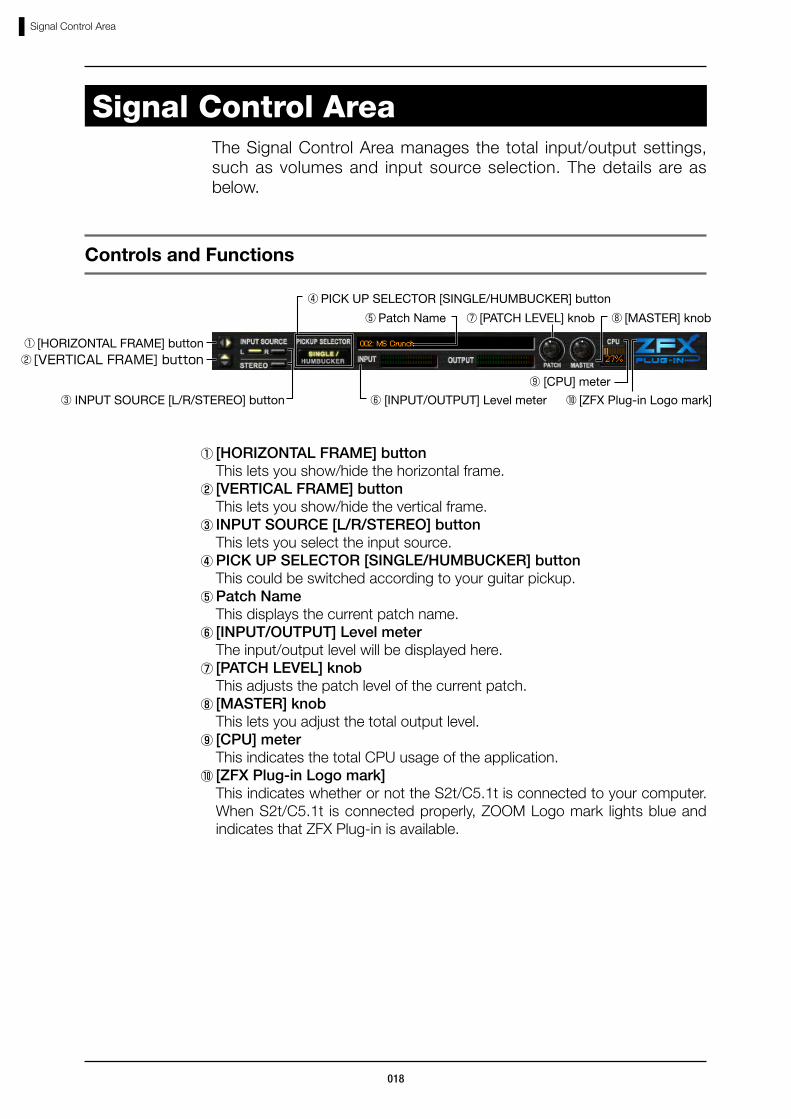
①[HORIZONTAL FRAME] button This lets you show/hide the horizontal frame.②[VERTICAL FRAME] button This lets you show/hide the vertical frame.③INPUT SOURCE [L/R/STEREO] button This lets you select the input source.④PICK UP SELECTOR [SINGLE/HUMBUCKER] button This could be switched according to your guitar pickup.⑤Patch Name This displays the current patch name.⑥[INPUT/OUTPUT] Level meter The input/output level will be displayed here.⑦[PATCH LEVEL] knob This adjusts the patch level of the current patch.⑧[MASTER] knob This lets you adjust the total output level.⑨[CPU] meter This indicates the total CPU usage of the application.⑩[ZFX Plug-in Logo mark] This indicates whether or not the S2t/C5.1t is connected to your computer.
When S2t/C5.1t is connected properly, ZOOM Logo mark lights blue and indicates that ZFX Plug-in is available.
Signal Control AreaThe Signal Control Area manages the total input/output settings, such as volumes and input source selection. The details are as below.
Controls and Functions
① [HORIZONTAL FRAME] button
⑦ [PATCH LEVEL] knob
⑥…[INPUT/OUTPUT] Level meter
④ PICK UP SELECTOR [SINGLE/HUMBUCKER] button
⑤ Patch Name
③ INPUT SOURCE [L/R/STEREO] button
②[VERTICAL…FRAME]…button
⑩ [ZFX Plug-in Logo mark]
⑧ [MASTER] knob
⑨…[CPU] meter

019
Signal Control Area
For electric guitar/bass, the pickup selection have to be set correctly. When a electric guitar is on use, the indication "SINGLE" should be lit for single coiled pickups, and "HUMBUCKER" for humbucker pickups. For electric bass, the "SINGLE" is for passive type, and "HUMBUCKER" is for active type. To change setting, click the button.
Selecting pickups
Selecting input source
When the instrument is connected to CH2/R input, click the INPUT SOURCE [R] button.
2.
When the instrument is connected to both CH1/L and CH/R inputs as a stereo source, click the INPUT SOURCE [STEREO] button.
3.
When the instrument is connected to CH1/L input, click the INPUT SOURCE [L] button.
1.
When guitar/bass is connected to the Hi-Z input, this setting will be ignored.
For microphones and line input instruments, click the button above until it lights off.
020
Signal Control Area
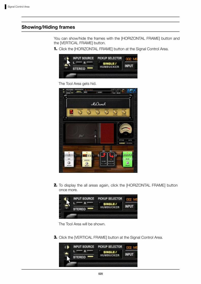
The Tool Area gets hid.
You can show/hide the frames with the [HORIZONTAL FRAME] button and the [VERTICAL FRAME] button.
Showing/Hiding frames
Click the [HORIZONTAL FRAME] button at the Signal Control Area.1.
To display the all areas again, click the [HORIZONTAL FRAME] button once more.
2.
The Tool Area will be shown.
Click the [VERTICAL FRAME] button at the Signal Control Area.3.

021
Signal Control Area
The setting you are currently editing gets lost when the new patch has been loaded. Store the settings as above if necessary. (→P058)
Patch level is the output level for the patch setting. To adjust it, drag the [PATCH] knob vertically. 0dB will be the unity gain (no increasing or decreasing). To store this setting, click the [STORE] button at the Patch Manager. The patch level will be stored with the current patch setting. (→P058)
Adjusting patch level
The Tool Area is still hidden after the [VERTICAL FRAME] button is clicked once again. To show all areas, click the [HORIZONTAL FRAME] button.
The all areas are shown when the ZFX Plug-in is booted.
All areas excluding the Signal Control Area gets hid.
The master level will not be stored as the patch setting.
The master level cannot be stored severally since it controls the total output level of the ZFX Plug-in. To adjust it, drag the [MASTER] knob vertically. 0dB will be the unity gain (no increasing or decreasing).
Adjusting master level
022
Signal Control Area
While using the ZFX Plug-in, please notice that the S2t/C5.1t is connected properly to your computer. With no connection, the copy-protection system runs and bypasses all the signals despite however the setting is.
When the S2t/C5.1t is connected properly to your computer, the [ZFX Plug-in Logo mark] at the Signal Control Area lights on. This lights off if no connection is detected.
About the connection state

023
Basic Operation
Basic Operation
At the Amplifier Section, you can control the knobs and switches to adjust the effect. At the Booth Section, microphone distance and position are adjustable for the better reverberation. You can also control the knobs and switches at the Effect Area. Here, the instruments can be wired freely with the shielded cables.
Below is the basic operation for the ZFX Plug-in. At first, choose an instrument from the Catalog, and drag-and-drop it to corresponding area or section. The Amplifier Section is for amplifiers, the Booth Section is for cabinets and microphones, and The Effect Area is for other instruments.

024
Catalog
Click the [CATALOG] button above the Tool Area.
Starting up the Catalog
CatalogThe effect types can be selected through the Catalog. The Catalog contains the various effect types including the amplifiers and effectors. There are two types of pages: the thumbnail page, and the detail page.
①Category This indicates the category of the instrument, which you are now viewing.
②Effect type name This indicates the name of the instrument.③Effect type image This is the image graphic of the instrument.④Index This lets you jump to the top page of each category.⑤Detail description This describes the character of the instrument.⑥[NEXT][PREVIOUS] Button These let you turn the pages.⑦Page index This indicates the current page index.
⑥…[NEXT][PREVIOUS] button
④ Index
①Category
⑤ Detail description
③ Effect type image
⑦ Page index
②…Effect type name
The corresponding LED lights on, and Catalog comes available. Below is its detail page.

025
Catalog
Click the [CATALOG] button above the Tool Area.1.
Below is the basic operation for both thumbnail and detail pages.
Pages can be turned with the [NEXT][PREVIOUS] buttons.
To turn to the previous page, click the [PREVIOUS] button.3.
The page turns back. With these buttons, the pages turn one by each.
The [PREVIOUS] button will not appear at the first page.
Besides using the [NEXT][PREVIOUS] button, you can also drag the blank part of the page to turn over.
Turning pages
The corresponding LED lights on, and the Catalog comes available.
The [NEXT] button and the [PREVIOUS] button appear when the mouse is hovering over the Catalog. To turn to the next page, click the [NEXT] button.
2.
The page turns over.
When the ZFX Plug-in is booted, the thumbnail page for the guitar amplifiers is shown as default.
Catalog - Basic operation

026
Catalog
Click the [CATALOG] button above the Tool Area.1.
By rolling the mouse wheel, you can turn a number of pages at once.
Hover the mouse over Catalog and roll the wheel backward.3.
The pages turn backwards this time.
Turning a number of pages
The corresponding LED lights on, and the Catalog comes available.
Hover the mouse over the Catalog, and roll the wheel upward.2.
The pages turn over at once.

027
Catalog
Click the [CATALOG] button above the Tool Area.1.
o jump between the categories, follow the instruction below. The distortion category is for example.
Jumping pages by index
The corresponding LED lights on, and the Catalog comes available.
Click the “DIST” index at the right side of Catalog.2.
The thumbnail page of the distortion effectors gets shown.
Do as same for other categories. Below are the details.3.①GUITAR index Guitar amplifiers②BASS index Bass amplifiers③CABINET index Guitar/Bass cabinets④MIC index Microphones⑤CMP/WAH index Dynamics/WAH effectors⑥DIST index Distortion effectors⑦MOD index Modulation effectors⑧DLY/REV index Delay/Reverb effectors⑨ TOOLS index Other instruments, typically the splitter and the
mixer.
028
Catalog
One category might include more than one thumbnail pages. With the indexes, their first pages become current. Click the [NEXT] button for the pages afterwards. (→P025)
Click the [CATALOG] button above the Tool Area.1.
With the thumbnail page, you can jump directly to the detail pages, or insert the instruments into the Amplifier Area and the Effect Area. The details are as below. The “DIST” category is for example.
The corresponding LED lights on, and the Catalog comes available.
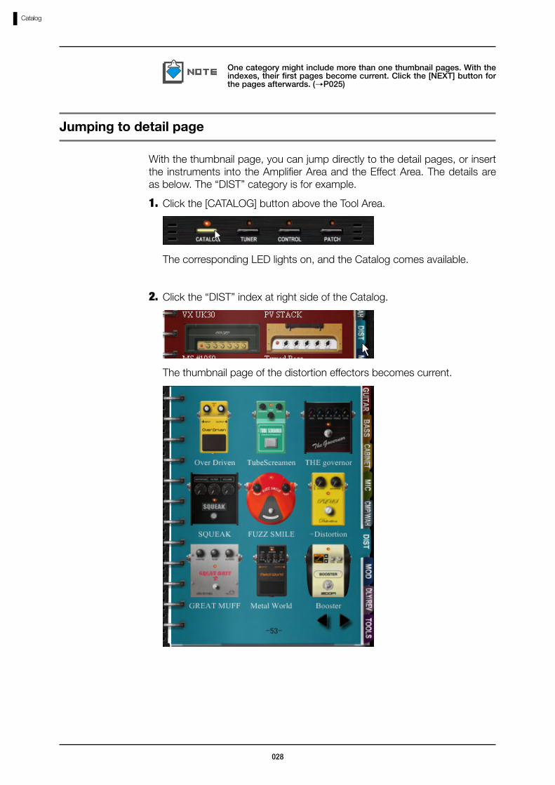
Click the “DIST” index at right side of the Catalog.2.
Jumping to detail page
The thumbnail page of the distortion effectors becomes current.
029
Catalog
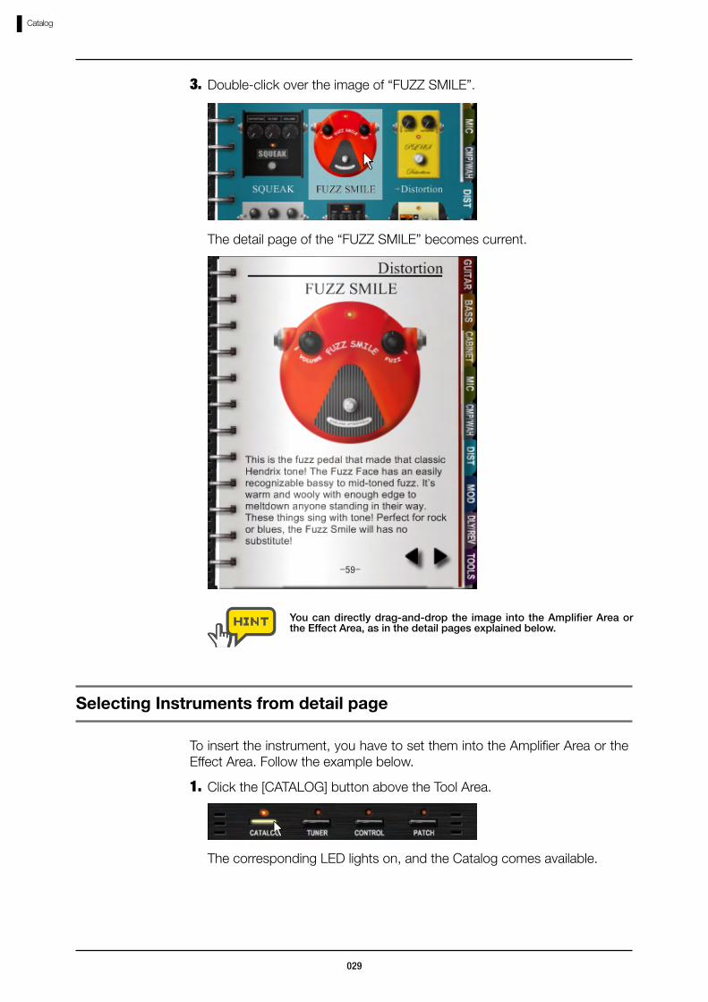
Double-click over the image of “FUZZ SMILE”.3.
You can directly drag-and-drop the image into the Amplifier Area or the Effect Area, as in the detail pages explained below.
The detail page of the “FUZZ SMILE” becomes current.
Selecting Instruments from detail page
Click the [CATALOG] button above the Tool Area.1.
To insert the instrument, you have to set them into the Amplifier Area or the Effect Area. Follow the example below.
The corresponding LED lights on, and the Catalog comes available.
030
Catalog
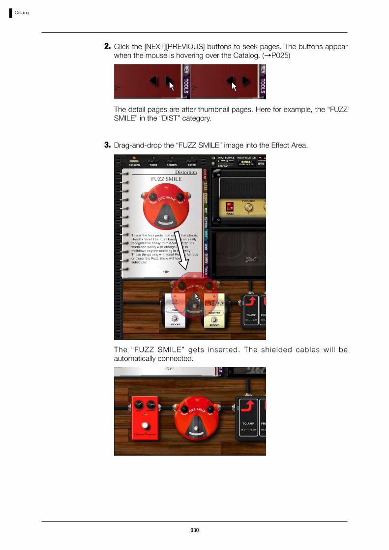
Click the [NEXT][PREVIOUS] buttons to seek pages. The buttons appear when the mouse is hovering over the Catalog. (→P025)
2.
The detail pages are after thumbnail pages. Here for example, the “FUZZ SMILE” in the “DIST” category.
Drag-and-drop the “FUZZ SMILE” image into the Effect Area.3.
The “FUZZ SMILE” gets inserted. The shielded cables wil l be automatically connected.

031
Amplifying Area
Controls and Functions
Amplifying AreaThe amplifier, cabinet, and microphone can be operated through the Amplifying Area. The amplifier belongs to the Amplifier Section, and the cabinet and microphone belong to the Booth Section. You can set and adjust them as below.
①Amplifier Section This section contains the amplifier.②Booth Section This section contains cabinet and microphone.③VU meter This indicates the final signal level after all effects
and master level.
① Amplifier Section
③ VU meter② Booth Section
When the amplifier is set from the Catalog, it can be adjusted and deleted through the Amplifier Section.
Amplifier Section - Basic operation
To set the amplifier, follow the instruction below. “1965 Bright Amp” is for example.
Setting Amplifiers

032
Amplifying Area
Drag-and-drop the “1965 Bright Amp” image into the Amplifier Section.3.
The amplifier gets set.
Click the “GUITAR” index at right side of the Catalog.2.
The thumbnail page for guitar amplifiers becomes current.
Click the [CATALOG] button above the Tool Area.1.
The corresponding LED lights on, and the Catalog comes available.
For the details of Catalog, refer “Catalog - Basic operation”. (→P025) For the details of Catalog thumbnails, refer “Jumping to detail page”. (→P028)
You can also set the amplifiers from the detail pages of the Catalog. You may drag-and-drop the image into the Amplifier Section. (→P029)

033
Amplifying Area
To adjust the effect tone of the amplifier, control the knobs and switches.
Adjusting Amplifiers
②Knob With dragging it vertically, you can adjust the belonging parameters.
② Knob① Switch
①Switch This lets you switch the channels or other belonging parameters.
Some instruments may contain other types of controls, but all controls can be operated through clicking and dragging.
The power switch of the amplifier cannot be edited.
To delete the amplifier, double-click the right button over it.
Deleting Amplifiers

034
Amplifying Area
The amplifier gets deleted.
You can also delete the amplifier, cabinet, and microphone at once by deleting the belonging amplifier module. (→P041)
When the cabinet and microphone are set from the Catalog, it can be adjusted and deleted through the Booth Section.
Booth Section - Basic operation
To set the cabinet into the Booth Section, follow the instruction below. “Bright Combo 2x12” is for example.
Setting Cabinets and Microphones
Click the [CATALOG] button above the Tool Area.1.
The corresponding LED lights on, and the Catalog comes available.
For the details of Catalog, refer “Catalog - Basic operation”.(→P025)For the details of Catalog thumbnails, refer “Jumping to detail page”. (→P028).
035
Amplifying Area
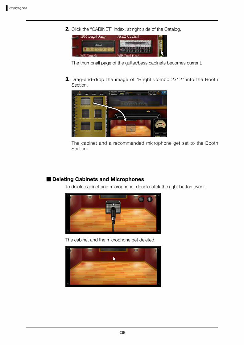
Click the “CABINET” index, at right side of the Catalog.2.
The thumbnail page of the guitar/bass cabinets becomes current.
Drag-and-drop the image of “Bright Combo 2x12” into the Booth Section.
3.
The cabinet and a recommended microphone get set to the Booth Section.
To delete cabinet and microphone, double-click the right button over it.
Deleting Cabinets and Microphones
The cabinet and the microphone get deleted.

036
Amplifying Area
Click the [CATALOG] button above the Tool Area.1.
The corresponding LED lights on, and the Catalog comes available.
To replace the microphone in Booth Section, follow the instruction below. “Dynamic 421” is for example.
Replacing Microphones
For the details of Catalog, refer “Catalog - Basic operation”.(→P025)For the details of Catalog thumbnails, refer “Jumping to detail page”. (→P028)
Click the “MIC” index at right side of the Catalog.2.
The thumbnail page of the microphones becomes current.
Drag-and-drop the image of “Dynamic421” into the Booth Section.3.
The microphone gets set into the Booth Section.
Hover the mouse over the Booth Section, and roll its wheel.The distance between microphone and cabinet can be adjusted.
Adjusting the microphone distance
The [+][-] button appears then the mouse is hovering over the Booth Section.The distance can also be adjusted through these buttons.
037
Amplifying Area
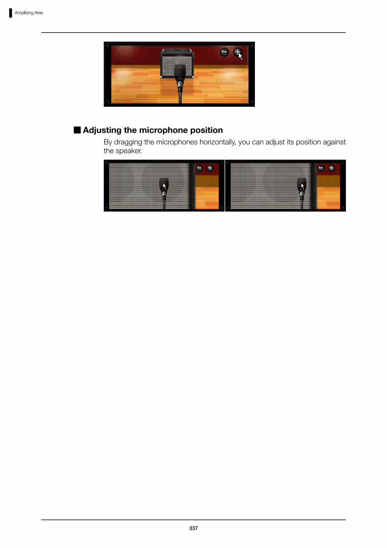
By dragging the microphones horizontally, you can adjust its position against the speaker.
Adjusting the microphone position

038
Effect Area
Controls and Functions
Effect AreaAt the Effect Area, you can set, adjust, and position the instruments, and wire the shielded cables freely.
① Shielded cable This connects the signal between the instruments.②Amplifier Module This sends the input signal to the Amplifying
Area, and processes the signal in following order: amplifier, cabinet, microphone. (→P053)
③ [+][-] buttons These let you magnify the view of the Effect Area.④ [LEFT][RIGHT] These let you zoom up the instruments one by
each.⑤ [INPUT] bar This can be used to connect the instruments to
the input signal of ZFX Plug-in.(→P047)⑥ Trash can This lets you delete the instruments and shielded
cables.⑦ [OUTPUT] bar This can be used to connect the instruments to
the output signal of ZFX Plug-in.(→P047)
③ [+][-] buttons
⑤ [INPUT] bar
① Shielded cable
⑦ [OUTPUT] bar
⑥…Trash can
② Amplifier Module
④ [LEFT][RIGHT] scroll buttons
Signal flow of Effect Area
The signal will be processed from left to right as below.
The shielded cables are available for both the stereo and monaural signals.
scroll buttons
039
Effect Area
Click the [CATALOG] button above the Tool Area.1.
The instruments which had been set from the Catalog can be adjusted and deleted.
To set the instrument into the Effect Section, follow the instruction below. “FUZZ SMILE” is for example.
Drag-and-drop the image of “FUZZ SMILE” into the Effect Area.3.
For the details of Catalog, refer “Catalog - Basic operation”. (→P025)For the details of Catalog thumbnails, refer “Jumping to detail page”. (→P028)
Setting instruments
The corresponding LED lights on, and the Catalog comes available.
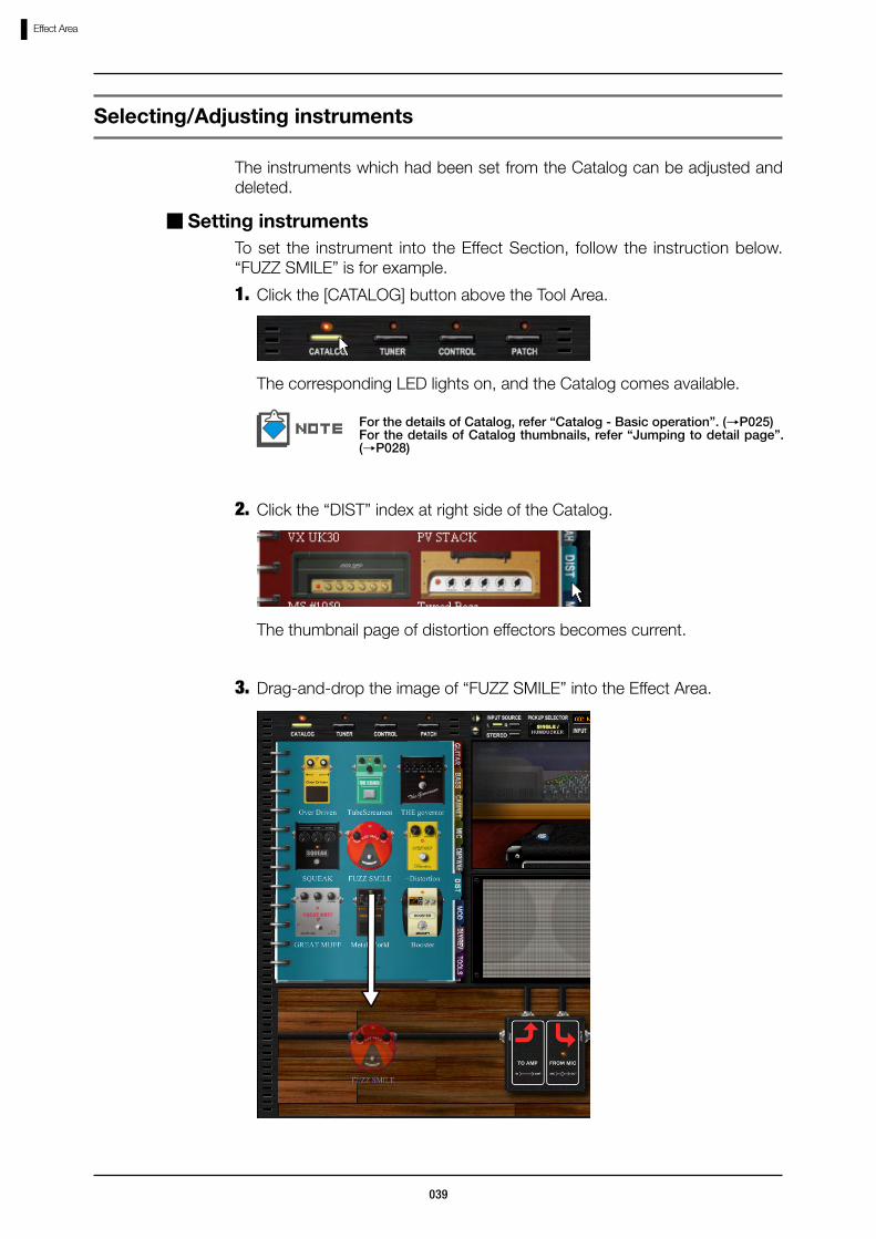
Click the “DIST” index at right side of the Catalog.2.
The thumbnail page of distortion effectors becomes current.
Selecting/Adjusting instruments

040
Effect Area
“FUZZ SMILE” gets inserted into the Effect Area, at the position where you have dropped.
In order to set the instruments, you can also drag-and-drop the image at the detail page of the Catalog.
The shielded cables will be connected automatically.
Start dragging the target instrument. Make sure that there are no knobs or switches at the start position.
1.
The instrument can be positioned freely with the drag-and-drop operation.
The shielded cables gets rewired automatically after this operation.
Positioning instruments
The translucent image of the instrument appears as the operation starts.
Drop the instrument to the destination.2.
The instrument moves to the destination.

041
Effect Area
To adjust the instrument, control its knobs and switches.
Adjusting instruments
①Knob With dragging it vertically, you can adjust the belonging parameters.
②[OUTPUT] jack The output signal will be sent out from here.③[INPUT] jack The output signal will be sent into here.④Foot switch This lets you to enable/disable the instrument.⑤Tool tip The tool tip appears while the parameters are
edited. This indicates its current value.
⑤ Tool tip
② [OUTPUT] jack① Knob
④ Foot switch③ [INPUT] jack
To adjust the knobs precisely, press the shift key while dragging. Then the knobs will turn slowly.
Some instruments may contain other types of controls, but all controls can be operated through clicking and dragging.
To delete the instruments, follow the instruction below.
Deleting instruments
Start dragging the target instrument. Make sure that there are no knobs or switches at the start position.
1.
The instrument starts dragging.

042
Effect Area
When the instrument is deleted, its previous and next instruments will be wired automatically.
Drop the instrument into the trash can icon at the right-bottom corner.2.
The instrument gets deleted.
You can also double-click the right button over the instrument to delete it.
To magnify the Effect Area, follow the instruction below.
Magnifying the Effect Area
Hover the mouse pointer over the Effect Area.1.
At the Effect Area, you can magnify and scroll the view.
Magnifying and Scrolling
043
Effect Area
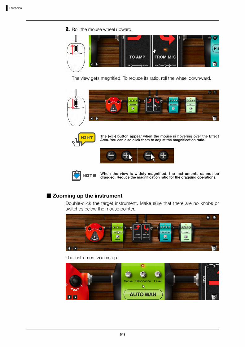
Roll the mouse wheel upward.2.
The view gets magnified. To reduce its ratio, roll the wheel downward.
The [+][-] button appear when the mouse is hovering over the Effect Area. You can also click them to adjust the magnification ratio.
When the view is widely magnified, the instruments cannot be dragged. Reduce the magnification ratio for the dragging operations.
Double-click the target instrument. Make sure that there are no knobs or switches below the mouse pointer.
Zooming up the instrument
The instrument zooms up.
044
Effect Area
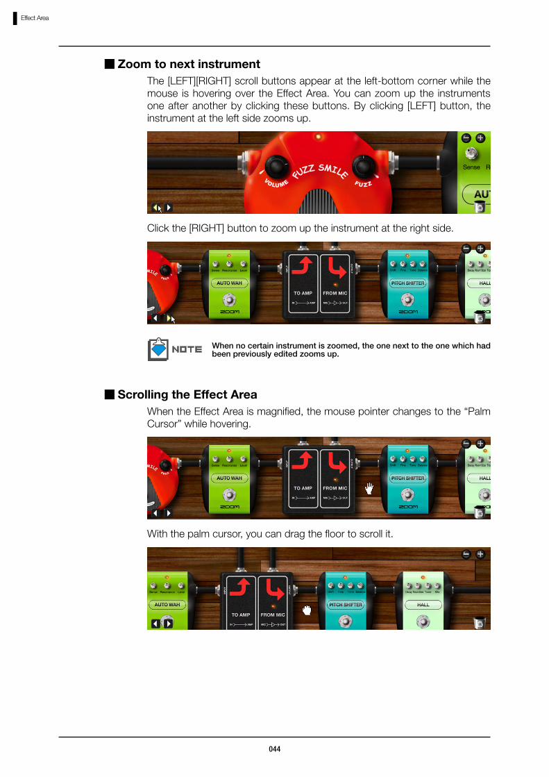
The [LEFT][RIGHT] scroll buttons appear at the left-bottom corner while the mouse is hovering over the Effect Area. You can zoom up the instruments one after another by clicking these buttons. By clicking [LEFT] button, the instrument at the left side zooms up.
Zoom to next instrument
Click the [RIGHT] button to zoom up the instrument at the right side.
When no certain instrument is zoomed, the one next to the one which had been previously edited zooms up.
When the Effect Area is magnified, the mouse pointer changes to the “Palm Cursor” while hovering.
Scrolling the Effect Area
With the palm cursor, you can drag the floor to scroll it.
045
Effect Area
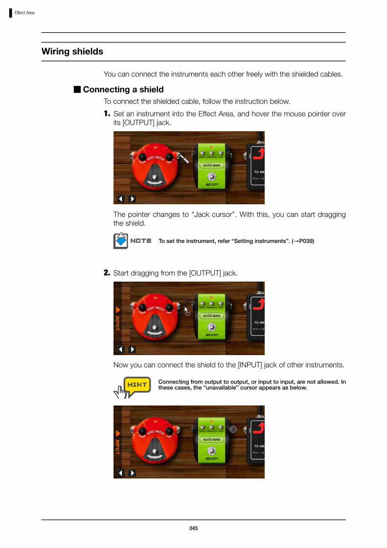
Set an instrument into the Effect Area, and hover the mouse pointer over its [OUTPUT] jack.
1.
You can connect the instruments each other freely with the shielded cables.
To connect the shielded cable, follow the instruction below.
To set the instrument, refer “Setting instruments”. (→P039)
Connecting a shield
The pointer changes to “Jack cursor”. With this, you can start dragging the shield.
Start dragging from the [OUTPUT] jack.2.
Now you can connect the shield to the [INPUT] jack of other instruments.
Wiring shields
Connecting from output to output, or input to input, are not allowed. In these cases, the “unavailable” cursor appears as below.

046
Effect Area
To cancel while dragging, drop it on the floor, or wherever beside jacks.
Drop it to the [INPUT] jack of other instrument.3.
Drag-and-drop from [OUTPUT] to the leftward [INPUT] is not allowed, since this may cause the feedback loop. From [INPUT] to the rightward [OUTPUT] is not allowed as well.
The shield will be connected. You can also start dragging from [INPUT], and then drop it to the [OUTPUT].
Start dragging the [INPUT][OUTPUT] jack, which the shield is connected.1.
To rewire the shields which are already connected, follow the instruction below.
Changing the shield connection
While dragging, the target shield turns green. Here you can rewire the shield.

047
Effect Area
The shielded cable gets rewired. When other instruments exist between the connection, the cable detours around them.
You can detour the shielded cables up side down if necessary. From upside to downside, drag-and-drop the jack downward.
From downside to upside, start dragging the jack and drop it upward.
You can also switch it up side down by double-clicking the jack.
Drop it to the [INPUT][OUTPUT] jack where you with to connect.2.
While dragging the jacks, the [INPUT][OUTPUT] bar appears at both sides of the Effect Area. You can drag the [INPUT] jack to the [INPUT] bar, in order to connect it directly to the input of ZFX Plug-in.
Connecting directly to input / output
048
Effect Area
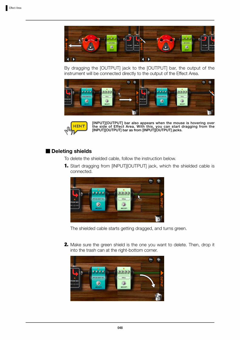
By dragging the [OUTPUT] jack to the [OUTPUT] bar, the output of the instrument will be connected directly to the output of the Effect Area.
[INPUT][OUTPUT] bar also appears when the mouse is hovering over the side of Effect Area. With this, you can start dragging from the [INPUT][OUTPUT] bar as from [INPUT][OUTPUT] jacks.
To delete the shielded cable, follow the instruction below.
Deleting shields
Start dragging from [INPUT][OUTPUT] jack, which the shielded cable is connected.
1.
The shielded cable starts getting dragged, and turns green.
Make sure the green shield is the one you want to delete. Then, drop it into the trash can at the right-bottom corner.
2.

049
Effect Area
To delete the shielded cables, you can also double-click right button over the jacks which they are connected.
The vertical shielded cables of the amplifier modules cannot be deleted.
The shield gets deleted.
Operating Splitters
Click the “TOOLS” index at right side of the Catalog.
Splitters and Mixers
At the Effect Area, you can split the signal into two by using “Splitter”, and two into one by “Mixer”. For these advanced operations, follow the instructions below.
The thumbnail page for “TOOLS” becomes current.1.
The thumbnail page for “TOOLS” will be shown.

050
Effect Area
Refer “Catalog - Basic operation” for the details of Catalog. (→P025)
Drag-and-drop the image of “Splitter” into the Effect Area.2.
The splitter gets inserted. As shown above, the splitter has two [OUTPUT] jacks. Both jacks output the signal, which had run into the splitter.
Both [OUTPUT] jacks can be wired the same way.
Refer “Jumping to detail page” for the details of thumbnail pages. (→P028)
Operating Mixers
Below is the instruction to operate the mixers.
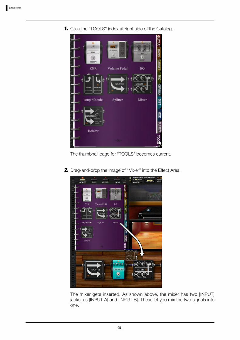
051
Effect Area
Click the “TOOLS” index at right side of the Catalog.1.
The thumbnail page for “TOOLS” becomes current.
Drag-and-drop the image of “Mixer” into the Effect Area.2.
The mixer gets inserted. As shown above, the mixer has two [INPUT] jacks, as [INPUT A] and [INPUT B]. These let you mix the two signals into one.

052
Effect Area
Both [INPUT] jacks can be wired the same way.
Connect the shielded cables to [INPUT A] and [INPUT B] jack.3.
Drag the [LEVEL A] knob vertically.4.
The channel A volume gets adjusted. Channel B volume can be adjusted with [LEVEL B] knob.
Drag the [PAN A] knob vertically.5.
The panning of the channel A gets adjusted. Turn clockwise to R side, and counterclockwise to L side. For the channel B panning, drag the [PAN B] knob.

053
Effect Area
The “Amplifier Module” sends the signal to the Amplifying Area. The “Amplifier Module” can be inserted multiply. When multiply inserted, each one of them corresponds to individual Amplifying Areas.
The Amplifying Area which is currently viewed, corresponds to the amplifier module indicated with red allow. To switch the view, click the other amplifier module.
Operating Multiple Amplifier Modules
Amplifier Module

054
Effect Area
The amplifier modules can be deleted as other instruments. The last amplifier module cannot be deleted since there must be at least one, though, by dropping it into the trash can, you can delete the containing amplifier, cabinet, and microphone.
Deleting Amplifier Modules

055
Patch Management
Starting up the Patch Manager
Patch ManagementThe patch setting including effect types and parameters, can be loaded/saved as patches. Patches are organized as bank, owning 128 patches. Bank corresponds to one file in your computer, and can be created as many as you want as far as your hard disk drive has enough space.
①[BANK SELECT] list The banks will be listed here.②Bank names The name and the index of banks are shown
here.③[BANK NEW] button This lets you create a new bank.④[BANK DELETE] button This lets you delete the current bank which is
currently selected.⑤[BANK IMPORT] button The external bank files can be imported with
⑥ [BANK EXPORT] button
④ [BANK DELETE] button
① [BANK SELECT] list
⑤ [BANK IMPORT] button
③ [BANK NEW] button
⑦ [PATCH SELECT] list
② Bank names
⑧ Patch names
⑨ [PATCH IMPORT] button ⑩ [PATCH EXPORT] button
⑪ [PATCH NEW] button
⑫ [PATCH DELETE] button
⑬ [STORE] button
⑭ [STORE AS] button
To start up the Patch Manager, follow the instruction below.
Click the [PATCH] button above the Tool Area.
The corresponding LED lights on, and the Patch Manager comes available.

056
Patch Management
Click the [PATCH] button above the Tool Area.1.
With the Patch Manager, you can select, store, create, and delete the patches.
To load these existing patches including presets, follow the instruction below.
Selecting patches
The corresponding LED lights on, and the Patch Manager comes available.
Operating patches
this button.⑥[BANK EXPORT] button The banks can be exported to an external file
with this button.⑦[PATCH SELECT] list The patches will be listed here. patches.⑧Patch names The name and the index of the patches are
shown here.⑨[PATCH IMPORT] button The external patch files can be imported with
this button.⑩[PATCH EXPORT] button The patches can be exported to an external
file with this button.⑪[PATCH NEW] button This clears the current patch setting.⑫[PATCH DELETE] button This lets you delete the patch which is
currently selected.⑬[STORE] button This lets you store the current setting to the
current patch.⑭[STORE AS] button This lets you store the current setting to the
other patches.

057
Patch Management
Click a bank name in the [BANK SELECT] list.2.
The [PATCH SELECT] list refreshes according to the bank you have selected. The current selection will be displayed inverted.
When the ZFX Plug-in is booted, the patch you had recently selected will be selected automatically.

058
Patch Management
Click a patch name in the [PATCH SELECT] list.3.
The patch setting gets loaded.
Click the [PATCH] button above the Tool Area.1.The effect setting can be stored as patches, which are owned by banks.
Storing patches
When the patch is loaded, your current patch setting gets lost, so that if necessary, store the setting before loading a new one. (→P058)
The corresponding LED lights on, and the Patch Manager comes available. The inverted bank and patch are the currents.

059
Patch Management
Make sure that you have stored the patch before loading a new one, since it would be lost.
Click the [PATCH] button above the Tool Area.1.To store the setting to the other patch, follow the instruction below.
Storing to certain destination
The corresponding LED lights on, and the Patch Manager comes available. The inverted bank and patch are the currents.
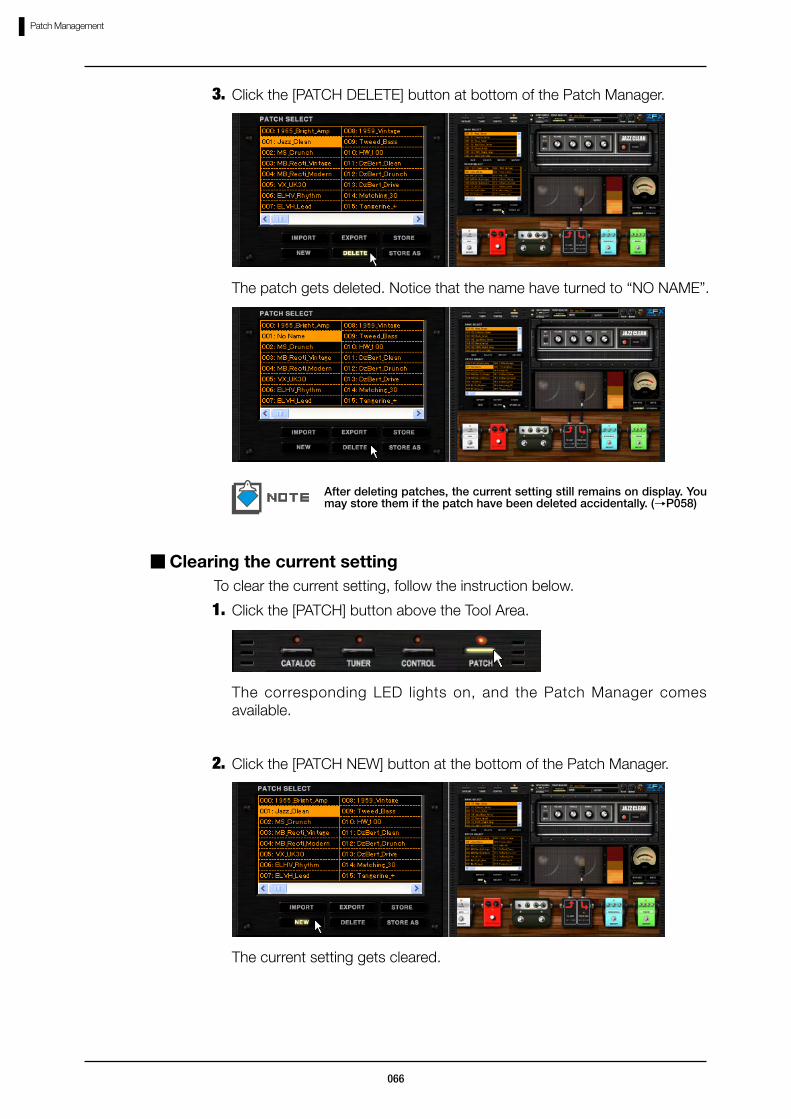
Click the [STORE] button at bottom of the Patch Manager.2.
The setting is now stored to the current patch.

060
Patch Management
Click the [STORE AS] button at the bottom of the Patch Manager.2.
Select the destination, as a new dialog appears as below.
①[TARGET BANK SELECT] list Select a target bank from here. The current will be shown inverted.
②[TARGET PATCH SELECT] list Select a target patch from here. The current will be shown inverted.
③[STORE] button This validates the storing operation according to the selection above.
① [TARGET BANK SELECT] list
② [TARGET PATCH SELECT] list
③ [STORE] button

061
Patch Management
Click a target bank from the [TARGET BANK SELECT] list.3.
The new selection inverts, and the corresponding patches will be listed below in [TARGET PATCH SELECT] list.
Click a target patch from the [TARGET PATCH SELECT] list.4.
The new selection inverts.

062
Patch Management
Click the [STORE] button at the bottom.5.
The setting is now stored to the patch which you have targeted.
Click the [PATCH] button above the Tool Area.1.To change the patch order, follow the instruction below.
Ordering patches
The corresponding LED lights on, and the Patch Manager comes available.
063
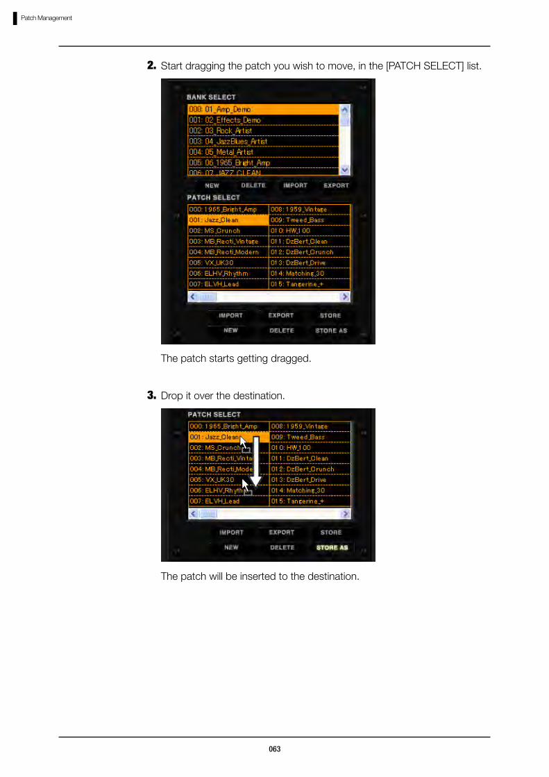
Patch Management
The patch starts getting dragged.
Start dragging the patch you wish to move, in the [PATCH SELECT] list.2.
Drop it over the destination.3.
The patch will be inserted to the destination.
064
Patch Management
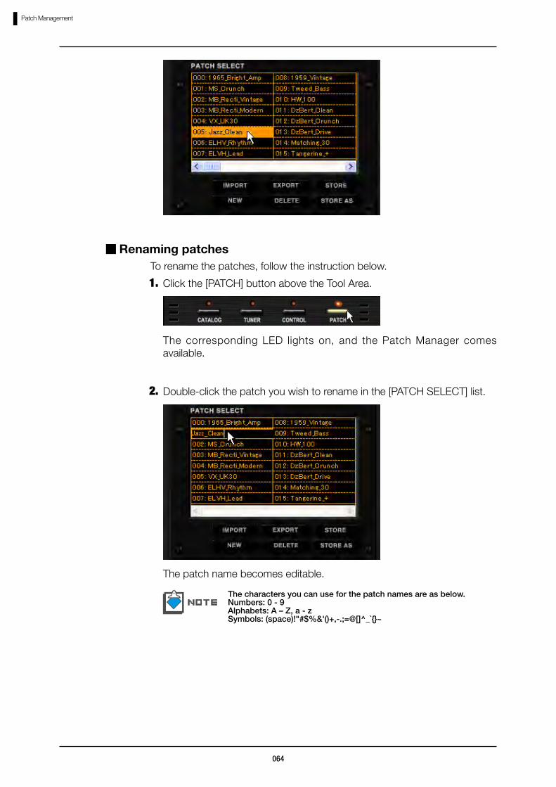
Click the [PATCH] button above the Tool Area.1.To rename the patches, follow the instruction below.
Renaming patches
The corresponding LED lights on, and the Patch Manager comes available.
Double-click the patch you wish to rename in the [PATCH SELECT] list.2.
The patch name becomes editable.
The characters you can use for the patch names are as below.Numbers: 0 - 9Alphabets: A – Z, a - zSymbols: (space)!"#$%&'()+,-.;=@[]^_`{}~
065
Patch Management
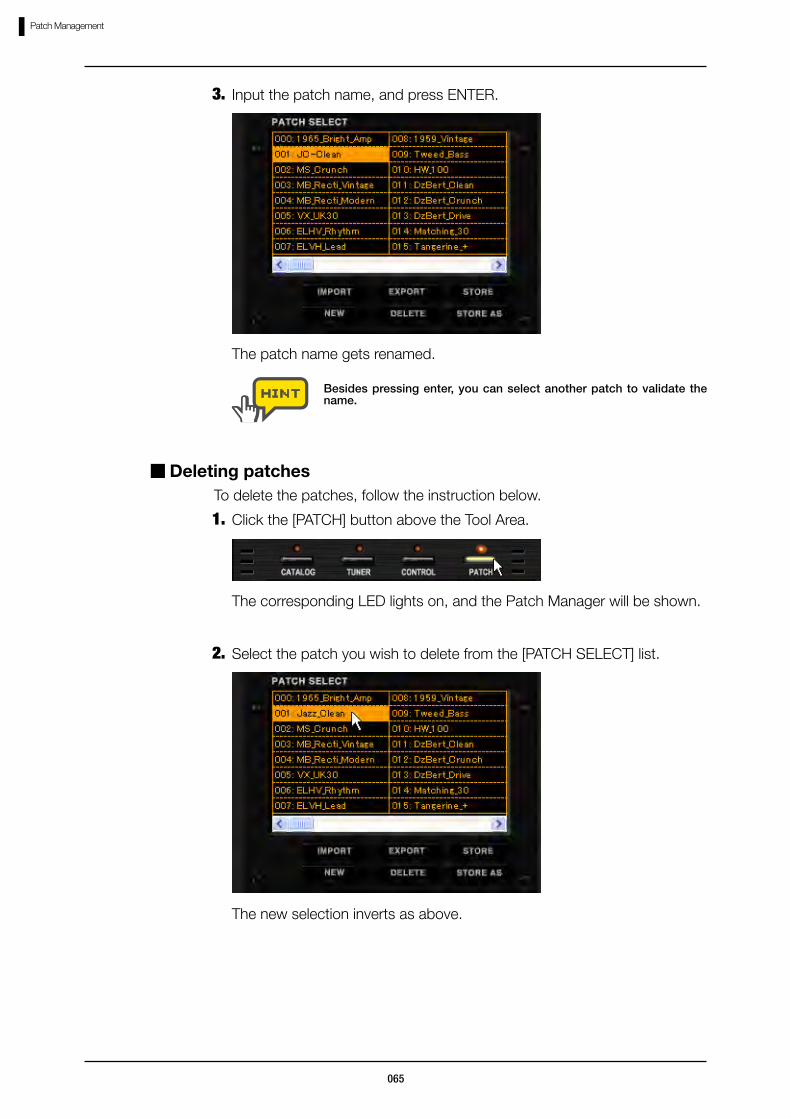
Besides pressing enter, you can select another patch to validate the name.
The patch name gets renamed.
Input the patch name, and press ENTER.3.
Click the [PATCH] button above the Tool Area.1.To delete the patches, follow the instruction below.
Deleting patches
The corresponding LED lights on, and the Patch Manager will be shown.
Select the patch you wish to delete from the [PATCH SELECT] list.2.
The new selection inverts as above.
066
Patch Management
The patch gets deleted. Notice that the name have turned to “NO NAME”.
After deleting patches, the current setting still remains on display. You may store them if the patch have been deleted accidentally. (→P058)
Click the [PATCH DELETE] button at bottom of the Patch Manager.3.
Click the [PATCH] button above the Tool Area.1.To clear the current setting, follow the instruction below.
Clearing the current setting
The corresponding LED lights on, and the Patch Manager comes available.
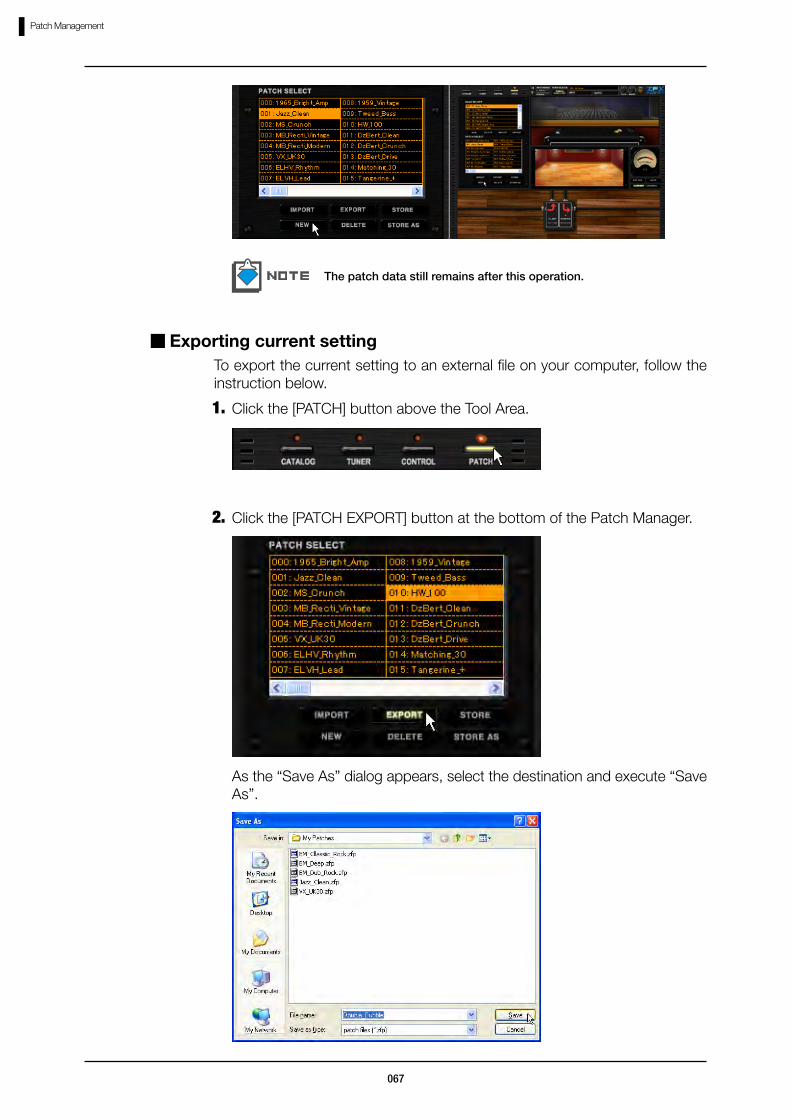
Click the [PATCH NEW] button at the bottom of the Patch Manager.2.
The current setting gets cleared.
067
Patch Management
The patch data still remains after this operation.
Click the [PATCH] button above the Tool Area.1.
To export the current setting to an external file on your computer, follow the instruction below.
Exporting current setting
Click the [PATCH EXPORT] button at the bottom of the Patch Manager.2.
As the “Save As” dialog appears, select the destination and execute “Save As”.
068
Patch Management
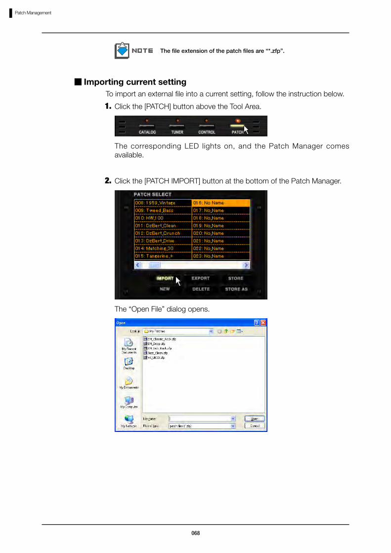
The file extension of the patch files are “*.zfp”.
Click the [PATCH] button above the Tool Area.1.To import an external file into a current setting, follow the instruction below.
Importing current setting
The corresponding LED lights on, and the Patch Manager comes available.
Click the [PATCH IMPORT] button at the bottom of the Patch Manager.2.
The “Open File” dialog opens.

069
Patch Management
Select and open the file (*.zfp) to import.3.
The effect setting gets loaded.
With the Patch Manager, you can create, delete, export, and import the banks. To get work with the banks, follow the instruction below.
Operating banks
Click the [PATCH] button above the Tool Area.1.
You can create banks with no limit as far as your hard disk drive has enough space. To create a new bank, follow the instruction below.
Creating a bank
The corresponding LED lights on, and the Patch Manager comes available.
070
Patch Management
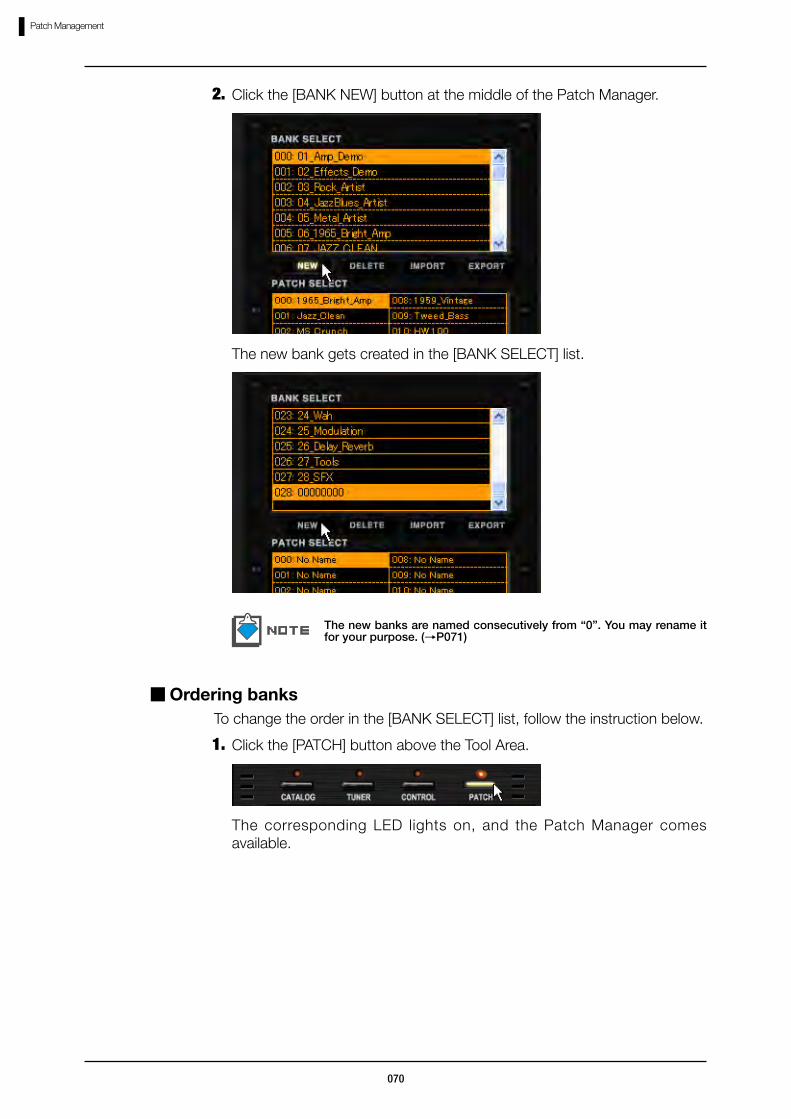
Click the [BANK NEW] button at the middle of the Patch Manager.2.
The new bank gets created in the [BANK SELECT] list.
The new banks are named consecutively from “0”. You may rename it for your purpose. (→P071)
Click the [PATCH] button above the Tool Area.1.To change the order in the [BANK SELECT] list, follow the instruction below.
Ordering banks
The corresponding LED lights on, and the Patch Manager comes available.

071
Patch Management
Start dragging the bank you wish to move in the [BANK SELECT] list.2.
The bank starts getting dragged.
Drop the bank at the destination.3.
The bank will be inserted to the destination.
Click the [PATCH] button above the Tool Area.1.To rename the bank, follow the instruction below.
Renaming banks
The corresponding LED lights on, and the Patch Manager comes available.

072
Patch Management
Double-click over the bank you wish to rename in the [BANK SELECT] list.
2.
The bank name becomes editable.
The characters you can use for the bank names are as below.Numbers: 0 - 9Alphabets: A – Z, a - zSymbols: (space)!"#$%&'()+,-.;=@[]^_`{}~
Input the bank name, and press ENTER to validate.3.
The bank gets renamed.
Besides pressing enter, you can select other banks in order to validate.
Click the [PATCH] button above the Tool Area.1.To delete the bank, follow the instruction below.
Deleting banks
The corresponding LED lights on, and the Patch Manager comes available.
073
Patch Management
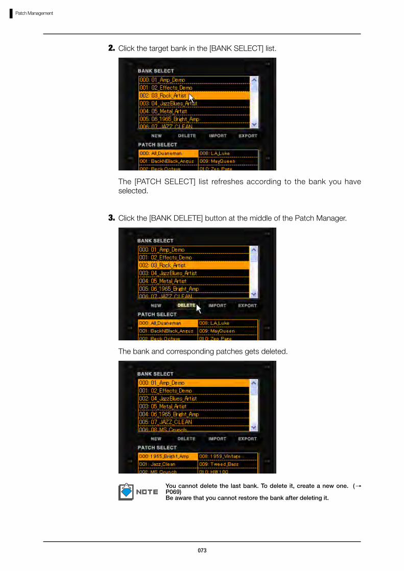
Click the target bank in the [BANK SELECT] list.2.
The [PATCH SELECT] list refreshes according to the bank you have selected.
Click the [BANK DELETE] button at the middle of the Patch Manager.3.
The bank and corresponding patches gets deleted.
You cannot delete the last bank. To delete it, create a new one. (→P069)Be aware that you cannot restore the bank after deleting it.
074
Patch Management
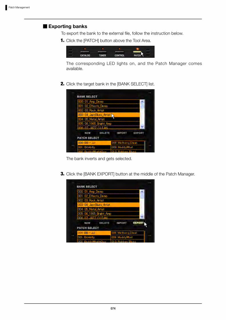
Click the [PATCH] button above the Tool Area.1.To export the bank to the external file, follow the instruction below.
Exporting banks
The corresponding LED lights on, and the Patch Manager comes available.
Click the target bank in the [BANK SELECT] list.2.
The bank inverts and gets selected.
Click the [BANK EXPORT] button at the middle of the Patch Manager.3.

075
Patch Management
The “Save As” dialog opens. Select the destination, and save the file.
The file extensions are *.zfb.
Press the [PATCH] button above the Tool Area.1.To import the external bank file, follow the instruction below.
Importing banks
The corresponding LED lights on, and the Patch Manager comes available.
Click the [BANK IMPORT] button at the middle of the Patch Manager.2.

076
Patch Management
The “Open File” dialog opens.
Open the external bank file (*.zfb).3.
The imported bank data will be added at the end of [BANK SELECT] list.

077
Bypassing Area
Controls and Functions
Bypassing AreaAt the Bypassing Area, you can bypass (disabling the effects) and mute (disabling the whole input) the sounds. Also with [CURRENT/ORIGINAL] button, you can compare the sounds between the current patch setting and its original patch setting, which have been recently stored.
① [BYPASS] button This button switches and indicates the bypass condition.
②[MUTE] button This button switches and indicates the mute condition.
③ [CURRENT/ORIGINAL] This lets you compare the current and the original patch setting.
① [BYPASS] button
③ [CURRENT/ORIGINAL] button
②…[MUTE] button
With the [BYPASS] button, you can bypass the effect setting. While bypassing, the [BYPASS] indication lights as below.
To end bypassing, click the [BYPASS] button once again.
Bypassing the sound
button

078
Bypassing Area
While the original setting is displayed, you cannot edit the effect setting, such as setting or deleting effect types, adjusting parameters, or rewiring the shields.
Be aware that the original setting will be overwritten with the current setting, when the patch is stored through [STORE] or [STORE AS]. (→P058)The [PATCH NEW] button clears only the current setting. (→P066)
With [CURRENT/ORIGINAL] button, you can compare the sounds between the current patch setting and its original patch setting, which have been recently stored. The condition switches as the button is pressed.
As above, the original state is shown in sepia tone, and the setting which have been recently stored will be displayed. The [CURRENT/ORIGINAL] button indicates the condition.
Comparing current and original state
With the [MUTE] button, you can mute the output sound. While muting, the [MUTE] indication lights as below.
To end muting, click the [MUTE] button once again.
Muting the sound

079
Tuner
To start up the tuner, follow the instruction below.
Starting up the tuner
TunerIn addition to the standard chromatic tuner, ZFX Plug-in supports the other tuning methods. You can also drop half or whole tone, or adjust the tuning calibration (the reference frequency). The details are as below.
①Pitch LED This indicates the precise pitch in resolution of five cents. When the pitch is high, the indication moves right, and when it is low, it moves left. At the just tune, the center LED lights on.
②High/Low LED When the pitch is high, the LED at the right side lights on, and when it is low, the LED at the left side lights on. The both get lit at the just tune.
⑥ [DOUBLE FLAT] button
④ Tuner mode
① Pitch LED
⑤ [TUNER MODE] button
③ The pitch name or the string number
⑦ [FLAT] button
②High/Low LED
The corresponding LED lights on, and the Tuner comes available.
Click the [TUNER] button above the Tool Area.
⑧Calibration value⑨ [CALIBRATION] button
080
Tuner
③The pitch name or With the chromatic tuner, this indicates the nearest pitch name. With other tuning methods, this indicates the string number, which have been played.
④Tuner mode This indicates the current tuner mode.⑤[TUNER MODE] button This lets you switch the tuner modes.⑥[DOUBLE FLAT] button This lets you tune your guitar with a whole
tone dropped.⑦[FLAT] button This lets you tune your guitar with a half tone
dropped.⑧Calibration value This indicates the calibration value, the
frequency to refer.⑨[CALIBRATION] button This increases and decreases the calibration
value.
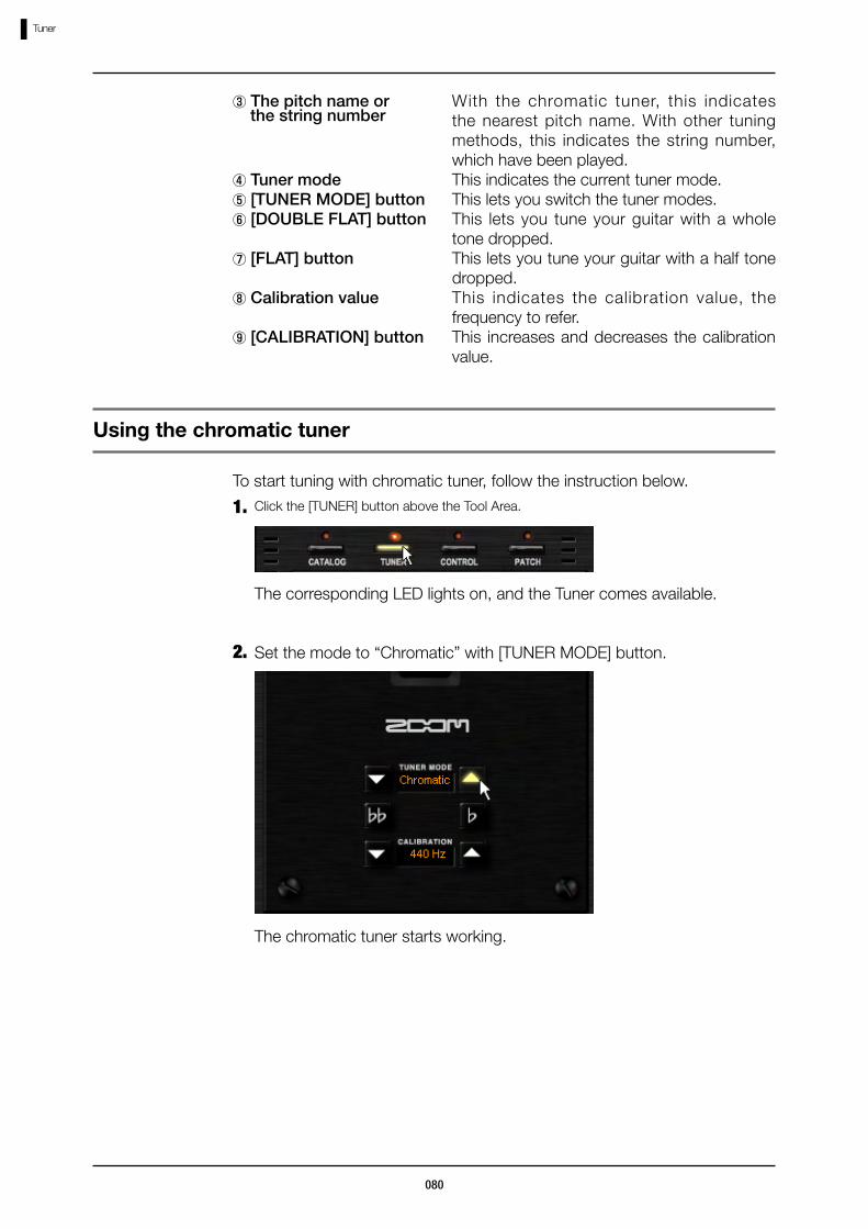
Click the [TUNER] button above the Tool Area.1.To start tuning with chromatic tuner, follow the instruction below.
The corresponding LED lights on, and the Tuner comes available.
Set the mode to “Chromatic” with [TUNER MODE] button.2.
Using the chromatic tuner
The chromatic tuner starts working.
the string number

081
Tuner
Play the string you are going to tune.3.
The nearest pitch name indicates as below.
Tune the string referring the pitch LED and the high/low LED. At the just tune, the center of the pitch LED lights on, as well the both high/low LED.
4.
You may tune roughly at first, until the right pitch name gets indicated, and then tune precisely referring the pitch LED and the high/low LED.
A
A#
B
C
C#
D
D#
E
F
F#
G
G#
Pitch name Indication Pitch name Indication
082
Tuner
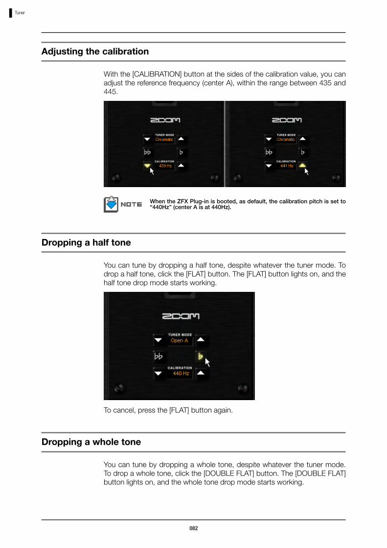
With the [CALIBRATION] button at the sides of the calibration value, you can adjust the reference frequency (center A), within the range between 435 and 445.
Adjusting the calibration
When the ZFX Plug-in is booted, as default, the calibration pitch is set to “440Hz” (center A is at 440Hz).
You can tune by dropping a half tone, despite whatever the tuner mode. To drop a half tone, click the [FLAT] button. The [FLAT] button lights on, and the half tone drop mode starts working.
Dropping a half tone
To cancel, press the [FLAT] button again.
You can tune by dropping a whole tone, despite whatever the tuner mode. To drop a whole tone, click the [DOUBLE FLAT] button. The [DOUBLE FLAT] button lights on, and the whole tone drop mode starts working.
Dropping a whole tone
083
Tuner
To cancel, press the [DOUBLE FLAT] button again.
You cannot enable both the [FLAT] and the [DOUBLE FLAT] at the same time.
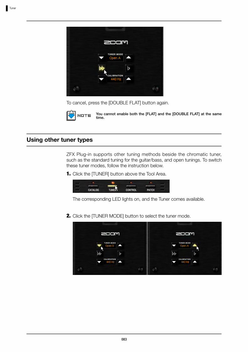
Click the [TUNER] button above the Tool Area.1.
ZFX Plug-in supports other tuning methods beside the chromatic tuner, such as the standard tuning for the guitar/bass, and open tunings. To switch these tuner modes, follow the instruction below.
The corresponding LED lights on, and the Tuner comes available.
Click the [TUNER MODE] button to select the tuner mode.2.
Using other tuner types
084
Tuner
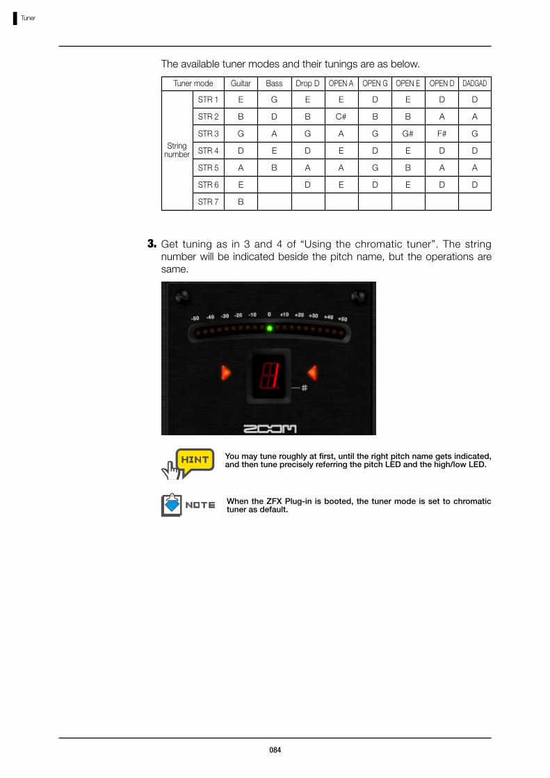
The available tuner modes and their tunings are as below.
Guitar Bass OPEN A OPEN G OPEN E OPEN D DADGAD
E
B
G
D
A
E
B
G
D
A
E
B
E
C#
A
E
A
E
D
B
G
D
G
D
E
B
G#
E
B
E
D
A
F#
D
A
D
D
A
G
D
A
D
Get tuning as in 3 and 4 of “Using the chromatic tuner”. The string number will be indicated beside the pitch name, but the operations are same.
3.
You may tune roughly at first, until the right pitch name gets indicated, and then tune precisely referring the pitch LED and the high/low LED.
When the ZFX Plug-in is booted, the tuner mode is set to chromatic tuner as default.
Drop D
E
B
G
D
A
D
Tuner mode
String number
STR 1
STR 2
STR 3
STR 4
STR 5
STR 6
STR 7
085
Expression pedal and foot switches
Starting up the Pedal/Switch Manager
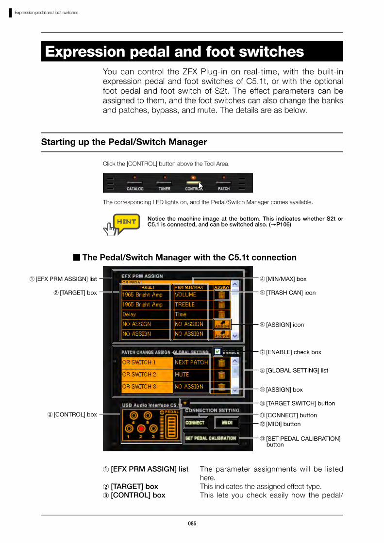
Expression pedal and foot switchesYou can control the ZFX Plug-in on real-time, with the built-in expression pedal and foot switches of C5.1t, or with the optional foot pedal and foot switch of S2t. The effect parameters can be assigned to them, and the foot switches can also change the banks and patches, bypass, and mute. The details are as below.
⑧ [GLOBAL SETTING] list
⑥ [ASSIGN] icon
① [EFX PRM ASSIGN] list
⑤ [TRASH CAN] icon
④ [MIN/MAX] box
⑨ [ASSIGN] box
② [TARGET] box
The corresponding LED lights on, and the Pedal/Switch Manager comes available.
Click the [CONTROL] button above the Tool Area.
⑦ [ENABLE] check box
③ [CONTROL] box
Notice the machine image at the bottom. This indicates whether S2t or C5.1 is connected, and can be switched also. (→P106)
The Pedal/Switch Manager with the C5.1t connection
⑩ [TARGET SWITCH] button
⑪ [CONNECT] button⑫ [MIDI] button
⑬ [SET PEDAL CALIBRATION] button
①[EFX PRM ASSIGN] list The parameter assignments will be listed here.
②[TARGET] box This indicates the assigned effect type.③[CONTROL] box This lets you check easily how the pedal/
086
Expression pedal and foot switches
switch works.④[MIN/MAX] box This indicates the assigned effect parameter
name, and lets you set the ava i lab le parameter range for each assignment.
⑤[TRASH CAN] icon This lets you delete the assignments.⑥[ASSIGN] icon You can assign the effect parameters to
pedals/switches through this icon.⑦[ENABLE] check box This enables the settings in the [GLOBAL
SETTING] list.⑧[GLOBAL SETTING] list The global assignments for the foot switches
will be listed here.⑨[ASSIGN] box This lets you assign the global settings.⑩[TARGET SWITCH] button This switches the machine image at the
[CONTROL] box, between S2t and C5.1t.⑪[CONNECT] button This indicates and switches the active ZFX
Plug-in, which receives the pedal/switch events, when multiply booted.(→P106)
⑫[MIDI] button This lets you receive the pedal/switch events through the MIDI message.
⑬[SET PEDAL This lets you adjust the built-in pedal of C5.1t.
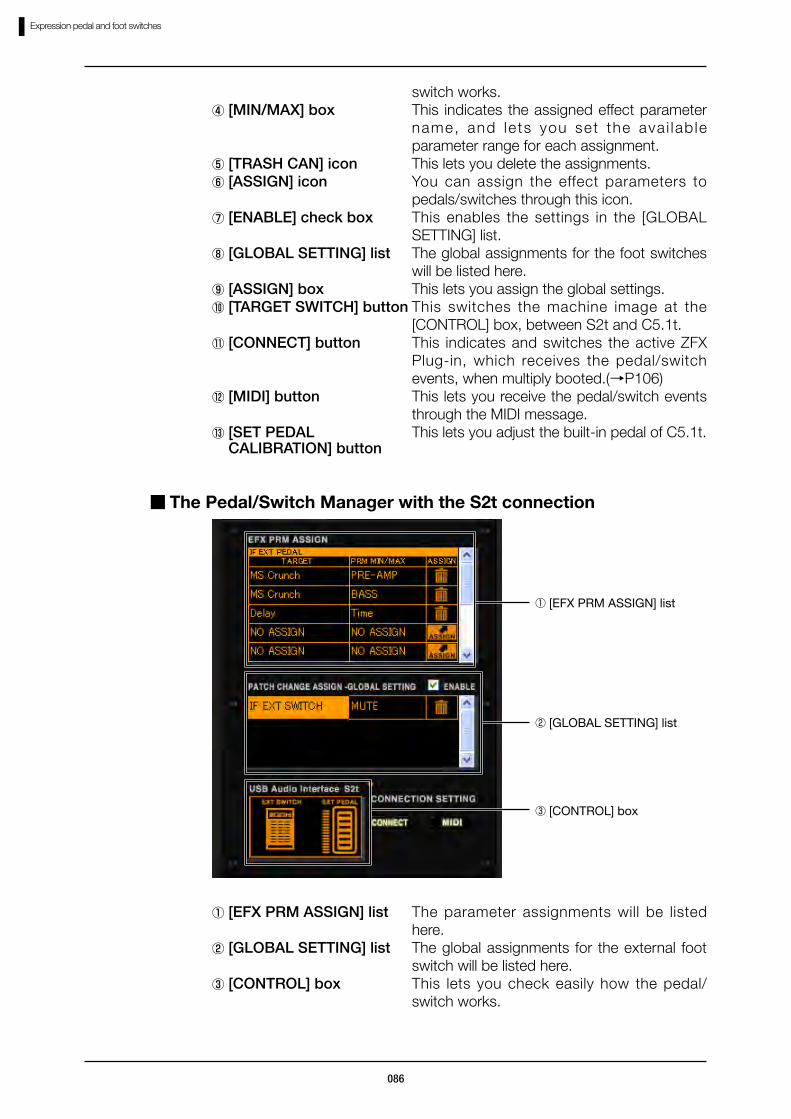
The Pedal/Switch Manager with the S2t connection
① [EFX PRM ASSIGN] list
② [GLOBAL SETTING] list
③ [CONTROL] box
CALIBRATION] button
①[EFX PRM ASSIGN] list The parameter assignments will be listed here.
②[GLOBAL SETTING] list The global assignments for the external foot switch will be listed here.
③[CONTROL] box This lets you check easily how the pedal/switch works.

087
Expression pedal and foot switches
To control the effect parameters through the foot switches and expression pedal, you have to assign the parameter at the [EFX PRM ASSIGN] list. To assign the parameters, follow the instruction below.
Assigning parameters
Assigning parameters to expression pedal
Assign the parameter to the C5.1t built-in expression pedal or the S2t external pedal as below. The “PEDAL BOX” is for example.
Click the [CONTROL] button above the Tool Area.1.
The corresponding LED lights on, and the Pedal/Switch Manager comes available.
Notice that the machine image in the [CONTROL] box is the one you have connected. If it differs, press the [TARGET SWITCH] button at the right top of [CONTROL] box, and select the proper machine. (→P106)

088
Expression pedal and foot switches
Scroll the [EFX PRM ASSIGN] list to the topmost. With C5.1t, [PEDAL] row will be displayed, and with S2t, [EXT PEDAL] row will be displayed.
2.
Start dragging the [ASSIGN] icon in the [EFX PRM ASSIGN] list, and drop it to the pedal of “PEDAL BOX”.
3.
The “WAH” parameter “WAH” of the “PEDAL BOX” will be assigned to the expression pedal.
089
Expression pedal and foot switches
You can assign five parameters maximum for each pedal/switch, and the parameters can be controlled simultaneously.
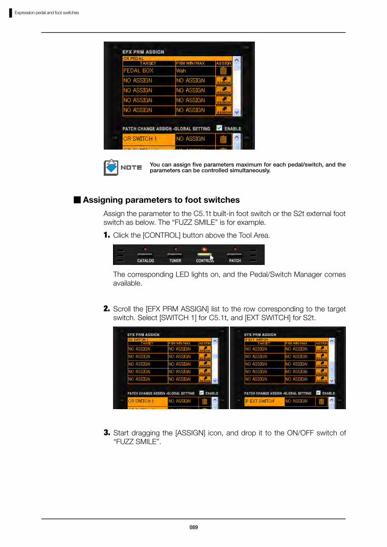
Assigning parameters to foot switches
Assign the parameter to the C5.1t built-in foot switch or the S2t external foot switch as below. The “FUZZ SMILE” is for example.
Click the [CONTROL] button above the Tool Area.1.
The corresponding LED lights on, and the Pedal/Switch Manager comes available.
Scroll the [EFX PRM ASSIGN] list to the row corresponding to the target switch. Select [SWITCH 1] for C5.1t, and [EXT SWITCH] for S2t.
2.
Start dragging the [ASSIGN] icon, and drop it to the ON/OFF switch of “FUZZ SMILE”.
3.

090
Expression pedal and foot switches
You can assign five parameters maximum for each pedal/switch, and the parameters can be controlled simultaneously.
The ON/OFF parameter of the “FUZZ SMILE” will be assigned to the switch.
Adjusting the parameter range
You can set the minimum and maximum value for each parameter assignment, in order to adjust its effective range.
Click the [CONTROL] button above the Tool Area.1.
The corresponding LED lights on, and the Pedal/Switch Manager comes available.
091
Expression pedal and foot switches
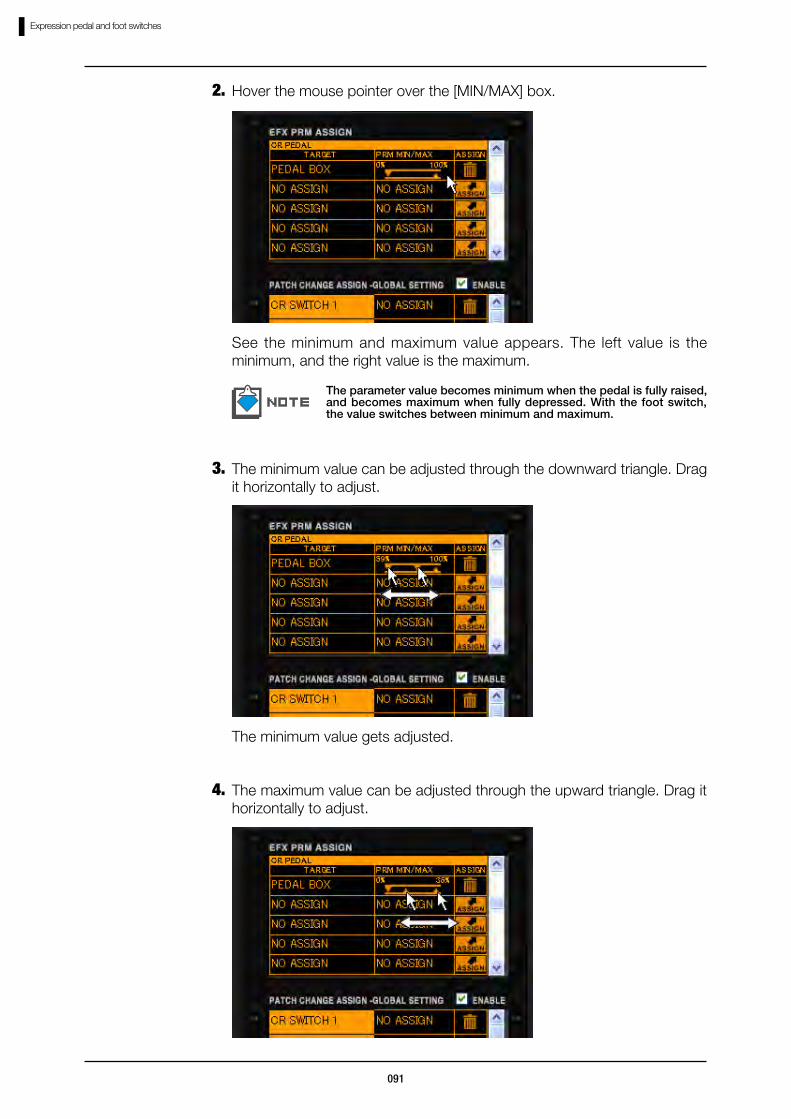
Hover the mouse pointer over the [MIN/MAX] box.2.
See the minimum and maximum value appears. The left value is the minimum, and the right value is the maximum.
The parameter value becomes minimum when the pedal is fully raised, and becomes maximum when fully depressed. With the foot switch, the value switches between minimum and maximum.
The minimum value can be adjusted through the downward triangle. Drag it horizontally to adjust.
3.
The minimum value gets adjusted.
The maximum value can be adjusted through the upward triangle. Drag it horizontally to adjust.
4.

092
Expression pedal and foot switches
The maximum value gets adjusted.
The available range depends to the effect parameter which have been assigned. “Minimum” value can be set higher than “Maximum” value. In this case, the parameter value becomes minimum when the pedal is fully depressed, and becomes maximum when fully raised.
Deleting the assignment
To delete the assignment of pedal/switche, follow the instruction below.
Click the [CONTROL] button above the Tool Area.1.
The corresponding LED lights on, and the Pedal/Switch Manager comes available.
Click the [TRASH CAN] icon in the [EFX PRM ASSIGN] list to delete the assignment.
2.
The assignment gets deleted.

093
Expression pedal and foot switches
The patch/bank selection, bypass, mute functions can be assigned to the C5.1t built-in switches, and the S2t external switch through the [GLOBAL SETTING] list. To assign these functions, follow the instruction below.
Assigning Global Settings
Assigning next/previous patch selection
Below is the assignment of the next/previous patch function. With this, you can move to the next patch or the previous patch. The C5.1t foot switch 1 is for example.
Click the [CONTROL] button above the Tool Area.1.
The corresponding LED lights on, and the Pedal/Switch Manager comes available.
Click the [ASSIGN] button at the row of the control, which you are going to assign. The “SWITCH 1” is for example.
2.
The function list appears as below.
094
Expression pedal and foot switches
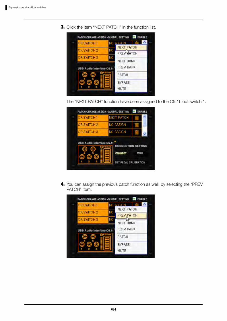
Click the item “NEXT PATCH” in the function list.3.
The “NEXT PATCH” function have been assigned to the C5.1t foot switch 1.
You can assign the previous patch function as well, by selecting the “PREV PATCH” item.
4.

095
Expression pedal and foot switches
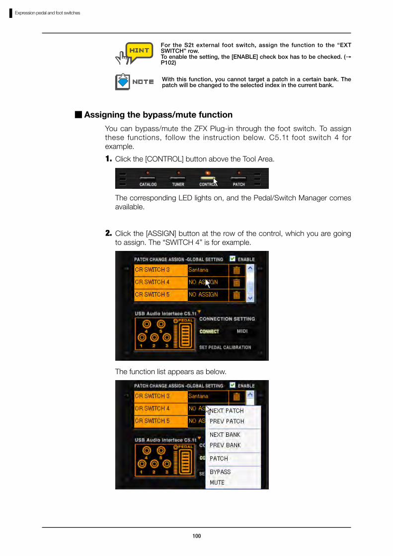
For the S2t external foot switch, assign the function to the “EXT SWITCH” row.
To enable the setting, the [ENABLE] check box has to be checked. (→P102)
Assigning next/previous bank selection
Below is the assignment of the next/previous bank function. With this, you can move to the next bank or to the previous bank. The C5.1t foot switch 2 is for example.
Click the [CONTROL] button above the Tool Area.1.
The corresponding LED lights on, and the Pedal/Switch Manager comes available.
Click the [ASSIGN] button at the row of the control, which you are going to assign. The “SWITCH 2” is for example.
2.
The function list appears as below.

096
Expression pedal and foot switches
Click the item “NEXT BANK” in the function list.3.
The next bank function have been assigned to the C5.1t foot switch 2.
You can assign the previous bank function as well, by selecting the “PREV BANK” item.
4.

097
Expression pedal and foot switches
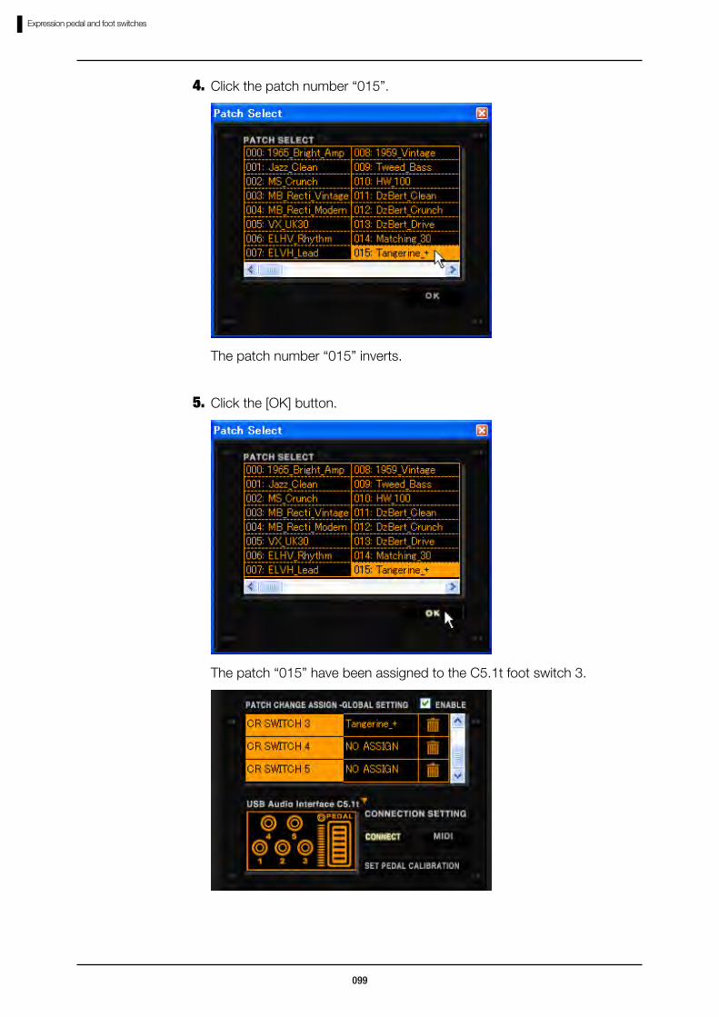
Assigning the patch selection
Below is the assignment of the patch bank function. With this, you can jump to the certain patch index you have assigned. The C5.1t foot switch 3, and the patch “015” is for example.
Click the [CONTROL] button above the Tool Area.1.
The corresponding LED lights on, and the Pedal/Switch Manager comes available.
Click the [ASSIGN] button at the row of the control, which you are going to assign. The “SWITCH 3” is for example.
2.
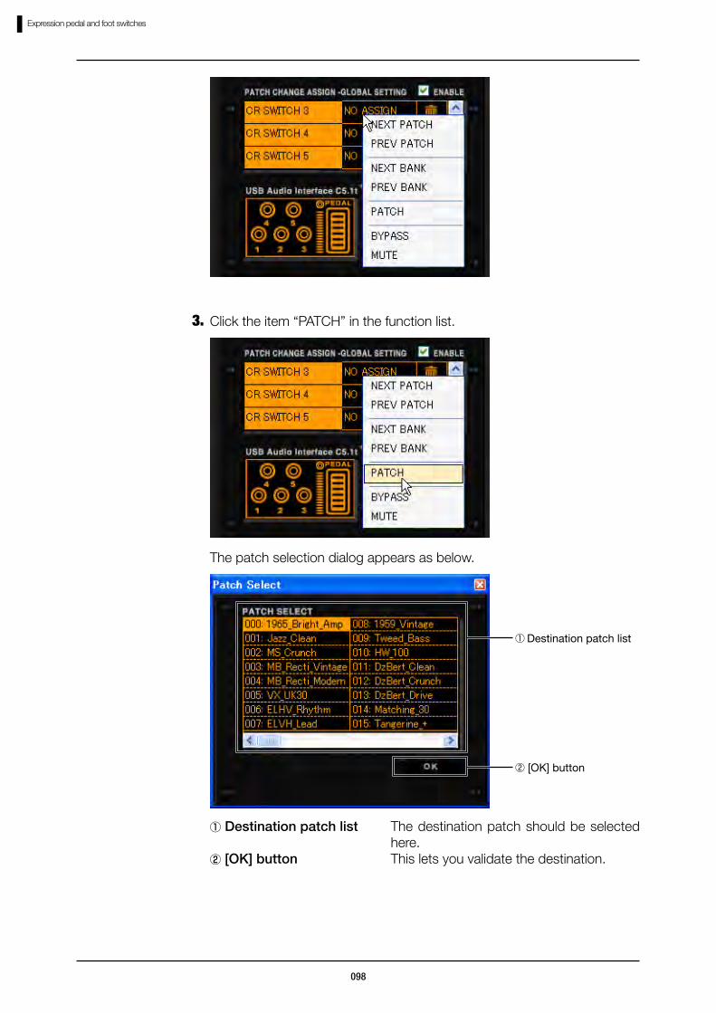
The function list appears as below.
For the S2t external foot switch, assign the function to the “EXT SWITCH” row.To enable the setting, the [ENABLE] check box has to be checked. (→P102)
After changing the bank, the patch change will occur according to the current patch index.
098
Expression pedal and foot switches
The patch selection dialog appears as below.
① Destination patch list The destination patch should be selected here.
② [OK] button This lets you validate the destination.
① Destination patch list
②…[OK] button
Click the item “PATCH” in the function list.3.
099
Expression pedal and foot switches
The patch number “015” inverts.
Click the patch number “015”.4.
The patch “015” have been assigned to the C5.1t foot switch 3.
Click the [OK] button.5.
100
Expression pedal and foot switches
For the S2t external foot switch, assign the function to the “EXT SWITCH” row.To enable the setting, the [ENABLE] check box has to be checked. (→P102)
With this function, you cannot target a patch in a certain bank. The patch will be changed to the selected index in the current bank.
Assigning the bypass/mute function
You can bypass/mute the ZFX Plug-in through the foot switch. To assign these functions, follow the instruction below. C5.1t foot switch 4 for example.
Click the [CONTROL] button above the Tool Area.1.
The corresponding LED lights on, and the Pedal/Switch Manager comes available.
Click the [ASSIGN] button at the row of the control, which you are going to assign. The “SWITCH 4” is for example.
2.
The function list appears as below.
101
Expression pedal and foot switches
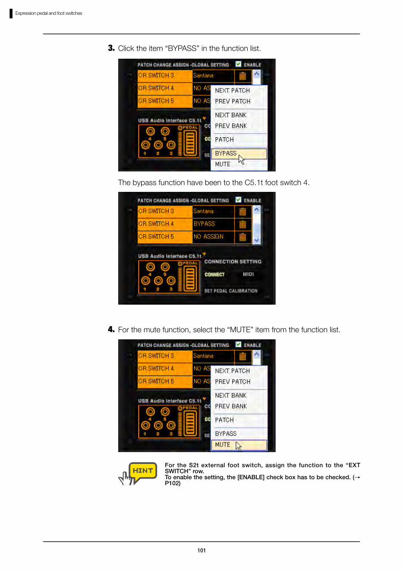
Click the item “BYPASS” in the function list.3.
The bypass function have been to the C5.1t foot switch 4.
For the S2t external foot switch, assign the function to the “EXT SWITCH” row.To enable the setting, the [ENABLE] check box has to be checked. (→P102)
For the mute function, select the “MUTE” item from the function list.4.

102
Expression pedal and foot switches
Enabling the Global Setting
To enable the assignments of the [GLOBAL SETTING] list, the [ENABLE] check box has to be clicked and checked as below.
With the check, the [GLOBAL SETTING] assignment will be enabled. When the [GLOBAL SETTING] assignments and the [EFX PRM ASSIGN] assignments compete each other at the same control, the [GLOBAL SETTING] will have the priority.
To disable the [GLOBAL SETTING] list, click the [ENABLE] check box again.
Canceling the assignment
To delete the assignment in the [GLOBAL SETTING] list, click the [TRASH CAN] icon at the corresponding row.
The assignment will be deleted.
103
Expression pedal and foot switches
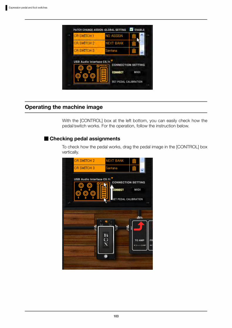
With the [CONTROL] box at the left bottom, you can easily check how the pedal/switch works. For the operation, follow the instruction below.
Operating the machine image
Checking pedal assignments
To check how the pedal works, drag the pedal image in the [CONTROL] box vertically.

104
Expression pedal and foot switches
The built-in pedal of C5.1t has a switch within, which can be triggered when the pedal is pushed into further after fully depressed. You can also assign an effect parameter to this switch in the [EFX PRM ASSIGN] list. To check its effect, click the switch aside the pedal image.
Checking foot switch assignments
To check how the foot switches work, click the switch image in the [CONTROL] box.
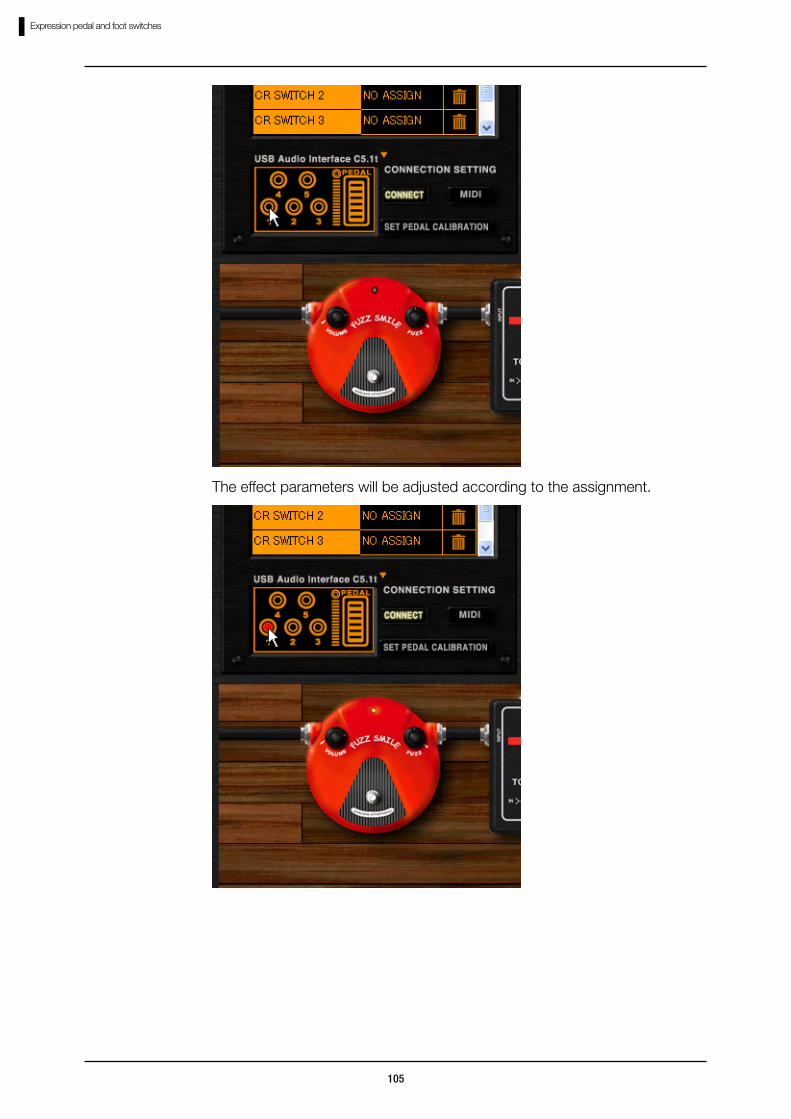
The effect parameters will be adjusted according to the assignment.
105
Expression pedal and foot switches
The effect parameters will be adjusted according to the assignment.
106
Expression pedal and foot switches
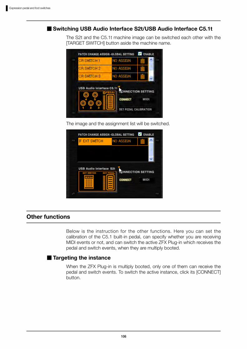
Switching USB Audio Interface S2t/USB Audio Interface C5.1t
The S2t and the C5.1t machine image can be switched each other with the [TARGET SWITCH] button aside the machine name.
The image and the assignment list will be switched.
Below is the instruction for the other functions. Here you can set the calibration of the C5.1 built-in pedal, can specify whether you are receiving MIDI events or not, and can switch the active ZFX Plug-in which receives the pedal and switch events, when they are multiply booted.
Other functions
Targeting the instance
When the ZFX Plug-in is multiply booted, only one of them can receive the pedal and switch events. To switch the active instance, click its [CONNECT] button.

107
Expression pedal and foot switches
The [CONNECT] button lights on, and the belonging plug-in starts receiving the pedal/switch events.
Click the [CONNECT] button again to cancel.
When the [CONNECT] button is on, the other ZFX Plug-in will be disconnected.
Receiving MIDI message
The switches and pedals of the C5.1t/S2t will send out the MIDI message. Generally, you can easily control the effects and patches when the [CONNECT] button is on(→106), but as a advanced use, you can automate the parameters through DAW applications with the MIDI messages. To receive the MIDI message to control the effects and patches, click the [MIDI] button.
For the details of the MIDI messages, refer the MIDI implementation chart. (→Appendix)
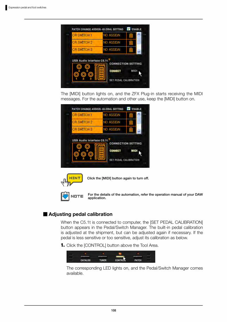
108
Expression pedal and foot switches
The [MIDI] button lights on, and the ZFX Plug-in starts receiving the MIDI messages. For the automation and other use, keep the [MIDI] button on.
Click the [MIDI] button again to turn off.
For the details of the automation, refer the operation manual of your DAW application.
Adjusting pedal calibration
When the C5.1t is connected to computer, the [SET PEDAL CALIBRATION] button appears in the Pedal/Switch Manager. The built-in pedal calibration is adjusted at the shipment, but can be adjusted again if necessary. If the pedal is less sensitive or too sensitive, adjust its calibration as below.
Click the [CONTROL] button above the Tool Area.1.
The corresponding LED lights on, and the Pedal/Switch Manager comes available.
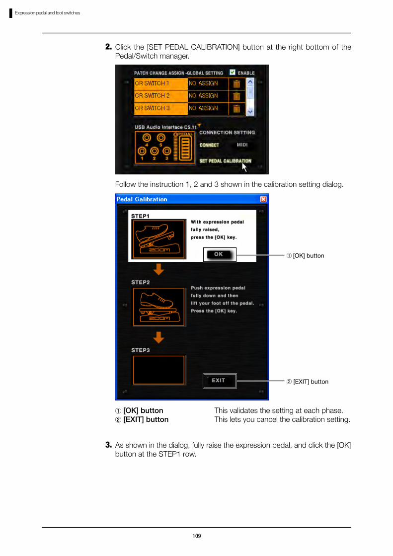
109
Expression pedal and foot switches
Click the [SET PEDAL CALIBRATION] button at the right bottom of the Pedal/Switch manager.
2.
Follow the instruction 1, 2 and 3 shown in the calibration setting dialog.
①[OK] button This validates the setting at each phase.② [EXIT] button This lets you cancel the calibration setting.
① [OK] button
② [EXIT] button
As shown in the dialog, fully raise the expression pedal, and click the [OK] button at the STEP1 row.
3.

110
Expression pedal and foot switches
The minimum value gets set.
Fully depress the expression pedal, lift your foot, and the click the [OK] button at the STEP2 row.
4.

111
Expression pedal and foot switches
The maximum value gets set.
Notice the “COMPLETE!” message appears in STEP3. Click the [EXIT] button to exit the dialog.
5.
The dialog closes. The [EXIT] button can be pressed at any phase to cancel the adjustment.
If the STEP3 indicates “ERROR!”, please restart the setting from 3 (STEP1).
The [SET PEDAL CALIBRATION] button will not appear when the S2t is connected.

112
Standalone mode
Open the “Start” menu of Windows, and select item “ZFX Plug-in” in “Program” -“ZOOM” - “ZFX Plug-in”.
Starting up the host application
Standalone modeZFX Plug-in can be booted standalone through the ZFX host application, with DAW applications. The host application has three menus, “File”, “Device”, and “Help”. The File menu lets you set the BPM and quit the application. With the Device menu, you can select and configure the ASIO drivers, and can connect/disconnect the C5.1t and the S2t. The Help menu lets you check the ZFX Plug-in version. See below for the detail.
ZFX Plug-in starts up standalone.
The item above might belong to the other folder, if it have been customized through installation.

113
Standalone mode
To open the Device menu, click the item “Device” in the menu bar, or press [ALT + D] key. Functions in the device menu are as below.
The available ASIO drivers are listed in the Device menu. See the current driver is checked. To switch, click the other device name.
Selecting ASIO driver
The ASIO driver switches. As default, ZOOM S2t C5.1t ASIO driver is checked. For other audio interfaces, select the driver which corresponds.
Device Menu
You can check the current device setting by clicking the item “Device Setting” in Device menu.
Configuring ASIO driver
To configure the ASIO driver setting, click “Control Panel” in Device Setting window.

114
Standalone mode
The control panel has a slider to adjust the audio latency. Please set it to the lowest value where there are no audible clicks or pops. The suitable value differs between the environments. With higher computer performance, the lower latency can be set. If not, the higher latency is recommended for the stability. The appearance of the control panel and the features which can be customized depend on ASIO driver.
To start the connection using the current ASIO driver, click the item “Connect” in the Device menu.
Connect/Disconnect
File Menu
To open the File menu, click the item “File” in the menu bar, or press [ALT + F] key. Functions in the File menu are as below.
To set the BPM, click the item “BPM Setting” in the File menu.
Setting BPM
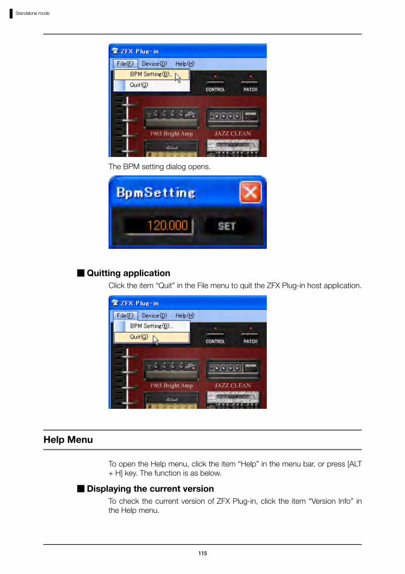
115
Standalone mode
The BPM setting dialog opens.
Click the item “Quit” in the File menu to quit the ZFX Plug-in host application.
Quitting application
Help Menu
To open the Help menu, click the item “Help” in the menu bar, or press [ALT + H] key. The function is as below.
To check the current version of ZFX Plug-in, click the item “Version Info” in the Help menu.
Displaying the current version
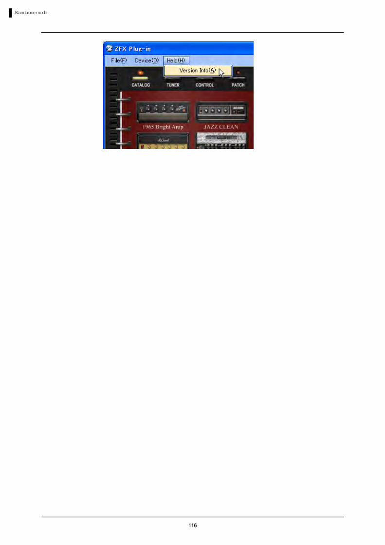
116
Standalone mode
117
Troubleshooting
●No sound or very low volume.・Make sure that C5.1t/S2t is connected properly to your computer through
USB cable.・Make sure that the C5.1t/S2t is connected properly to your computer with
USB cable.・Try adjusting the [GAIN], [PHONE], and [OUTPUT] knob of the C5.1t/S2t.・Make sure that the shielded cable is not defective.・Try adjusting the [PATCH LEVEL] knob of the ZFX Plug-in. (→P021)・Try adjusting the [MASTER LEVEL] knob of the ZFX Plug-in. (→P021)・Make sure the ZFX Plug-in is not in mute condition. (→P078)・For some patches, the volume can be adjusted with an expression pedal.
Make sure that a suitable volume setting has been selected with the pedal.・Try adjusting the Gain/Level parameters of the amplifiers and effectors in
use.・Make sure the input source setting of the ZFX Plug-in. (→P019)・Make sure that the PICKUP SELECTOR is properly selected. (→P019)・Make sure that the device configuration is proper. (→P113)●Noise is noticeable・Insert and adjust the ZNR module to your patch.・Try lowering the Gain and Level parameters of the amplifiers and distortion
effectors of the ZFX Plug-in.・Check the settings of expression pedals (→P085). Depending on its
parameter assignment, a pedal action may cause drastic parameter change and result in noise.・The deterioration, disconnection, or dirt of the guitar and shielded cables
may affect. Check these peripheral devices before use.●The C5.1t/S2t cannot be detected by your computer・Check that your operating system is adaptive.●The effect does not work・Check the LED of the inserted effect. The LED lights on when powered.・Make sure the shielded cables are connected properly to the insert effect.・Make sure the ZFX Plug-in is not in bypass condition. (→P077)●The tuner does not work・Make sure that the input source is selected properly according to your
connection. (→P019)
Troubleshooting

Appendix: Effect Types and Parameters
Appendix-1
Appendix: Effect Types and Parameters
Guitar Amplifier
1965 BRIGHT AMP
Simulation of the Fender TwinReverb '65.
BRIGHT ON/OFF
Enriches the high frequency range when turned on.
VOLUME 1.00 - 10.00
Adjusts the preamp gain (distortion depth).
TREBLE 1.00 - 10.00
Adjusts boost/cut in the high frequency range.
MIDDLE 1.00 - 10.00
Adjusts boost/cut in the middle frequency range.
BASS 1.00 - 10.00
Adjusts boost/cut in the low frequency range.
JAZZ CLEAN
Simulation of the Roland JC-120.
BRIGHT ON/OFF
Enriches the high frequency range when turned on.
VOLUME 0.00 - 10.00
Adjusts the preamp gain (distortion depth).
TREBLE 0.00 - 10.00
Adjusts boost/cut in the high frequency range.
MIDDLE 0.00 - 10.00
Adjusts boost/cut in the middle frequency range.
BASS 0.00 - 10.00
Adjusts boost/cut in the low frequency range.
MS CRUNCH
Simulation of the Marshall JCM800.
PRESENCE 0.00 - 10.00
Adjusts boost/cut in the very high frequency range.
BASS 0.00 - 10.00
Adjusts boost/cut in the low frequency range.

Appendix: Effect Types and Parameters
Appendix-2
MIDDLE 0.00 - 10.00
Adjusts boost/cut in the middle frequency range.
TREBLE 0.00 - 10.00
Adjusts boost/cut in the high frequency range.
MASTER VOLUME 0.00 - 10.00
Adjusts the signal level after the process.
PRE-AMP VOLUME 0.00 - 10.00
Adjusts the preamp gain (distortion depth).
MB DUAL HEAD
Simulation of the Mesa Boogie Dual Rectifier.
CHANNEL CLEAN: Channel suited for the clean sounds.
VINTAGE: High gain channel suited for the lead sounds.
MODERN: High gain channel with high frequency emphasis.
Selects the amplifier channel.
PRESENCE 0.00 - 10.00
Adjusts boost/cut in the very high frequency range.
MASTER 0.00 - 10.00
Adjusts the signal level after the process.
GAIN 0.00 - 10.00
Adjusts the preamp gain (distortion depth).
BASS 0.00 - 10.00
Adjusts boost/cut in the low frequency range.
MID 0.00 - 10.00
Adjusts boost/cut in the middle frequency range.
TREBLE 0.00 - 10.00
Adjusts boost/cut in the high frequency range.
VX UK30
Simulation of the Vox AC30TBX.
BRILLIANT 0.00 - 10.00
Adjusts the preamp gain (distortion depth).
TREBLE 0.00 - 10.00
Adjusts boost/cut in the high frequency range.
BASS 0.00 - 10.00
Adjusts boost/cut in the low frequency range.
CUT 0.00 - 10.00
Adjusts cut in the high frequency range.
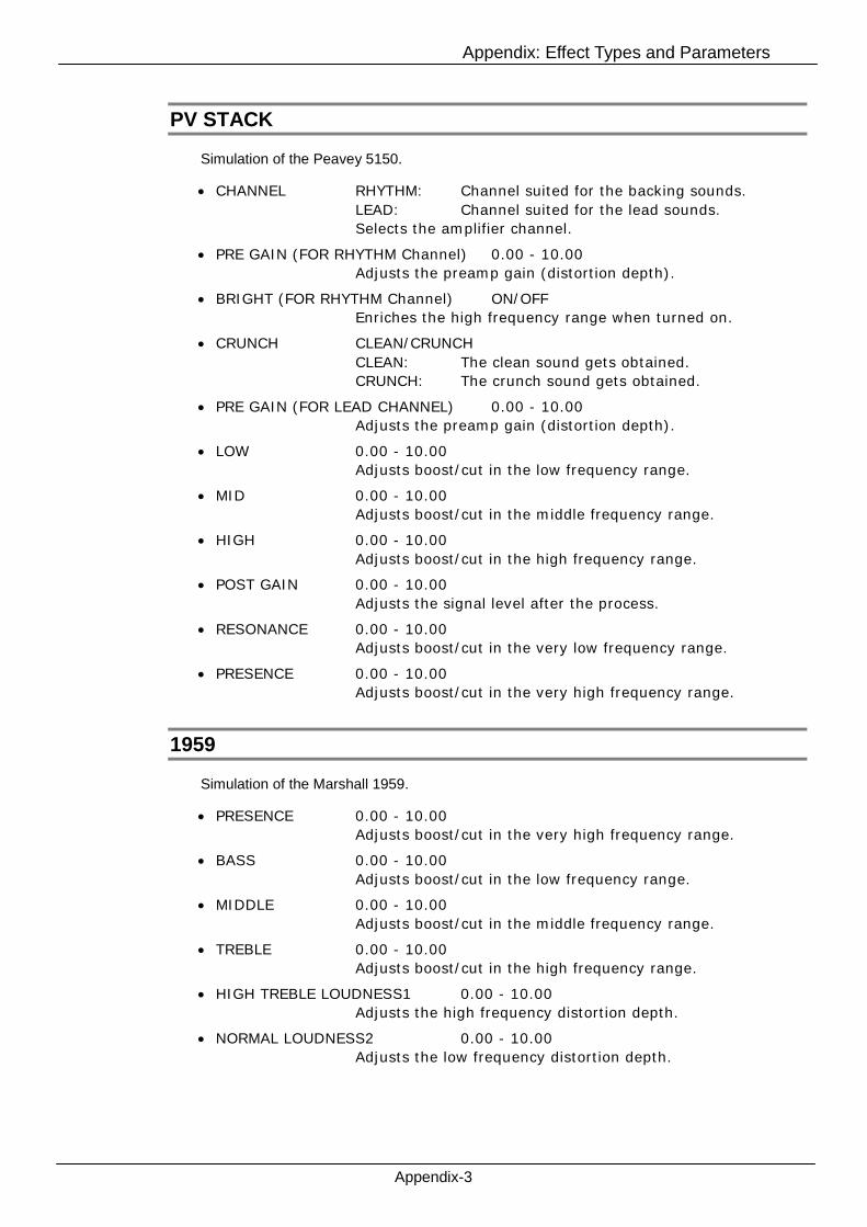
Appendix: Effect Types and Parameters
Appendix-3
PV STACK
Simulation of the Peavey 5150.
CHANNEL RHYTHM: Channel suited for the backing sounds.
LEAD: Channel suited for the lead sounds.
Selects the amplifier channel.
PRE GAIN (FOR RHYTHM Channel) 0.00 - 10.00
Adjusts the preamp gain (distortion depth).
BRIGHT (FOR RHYTHM Channel) ON/OFF
Enriches the high frequency range when turned on.
CRUNCH CLEAN/CRUNCH
CLEAN: The clean sound gets obtained.
CRUNCH: The crunch sound gets obtained.
PRE GAIN (FOR LEAD CHANNEL) 0.00 - 10.00
Adjusts the preamp gain (distortion depth).
LOW 0.00 - 10.00
Adjusts boost/cut in the low frequency range.
MID 0.00 - 10.00
Adjusts boost/cut in the middle frequency range.
HIGH 0.00 - 10.00
Adjusts boost/cut in the high frequency range.
POST GAIN 0.00 - 10.00
Adjusts the signal level after the process.
RESONANCE 0.00 - 10.00
Adjusts boost/cut in the very low frequency range.
PRESENCE 0.00 - 10.00
Adjusts boost/cut in the very high frequency range.
1959
Simulation of the Marshall 1959.
PRESENCE 0.00 - 10.00
Adjusts boost/cut in the very high frequency range.
BASS 0.00 - 10.00
Adjusts boost/cut in the low frequency range.
MIDDLE 0.00 - 10.00
Adjusts boost/cut in the middle frequency range.
TREBLE 0.00 - 10.00
Adjusts boost/cut in the high frequency range.
HIGH TREBLE LOUDNESS1 0.00 - 10.00
Adjusts the high frequency distortion depth.
NORMAL LOUDNESS2 0.00 - 10.00
Adjusts the low frequency distortion depth.
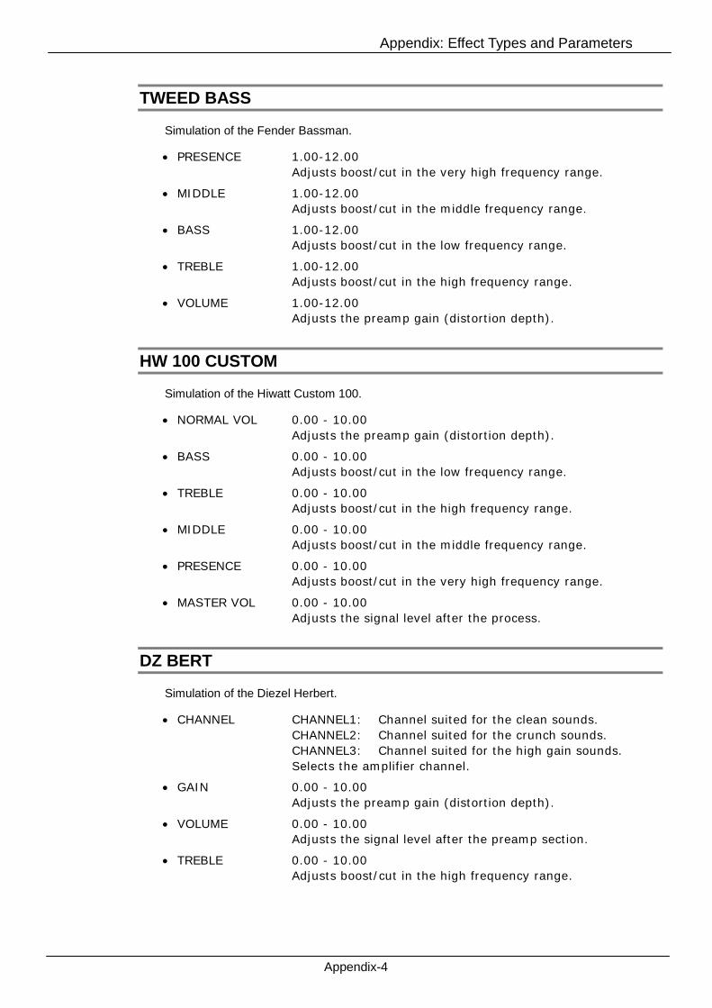
Appendix: Effect Types and Parameters
Appendix-4
TWEED BASS
Simulation of the Fender Bassman.
PRESENCE 1.00-12.00
Adjusts boost/cut in the very high frequency range.
MIDDLE 1.00-12.00
Adjusts boost/cut in the middle frequency range.
BASS 1.00-12.00
Adjusts boost/cut in the low frequency range.
TREBLE 1.00-12.00
Adjusts boost/cut in the high frequency range.
VOLUME 1.00-12.00
Adjusts the preamp gain (distortion depth).
HW 100 CUSTOM
Simulation of the Hiwatt Custom 100.
NORMAL VOL 0.00 - 10.00
Adjusts the preamp gain (distortion depth).
BASS 0.00 - 10.00
Adjusts boost/cut in the low frequency range.
TREBLE 0.00 - 10.00
Adjusts boost/cut in the high frequency range.
MIDDLE 0.00 - 10.00
Adjusts boost/cut in the middle frequency range.
PRESENCE 0.00 - 10.00
Adjusts boost/cut in the very high frequency range.
MASTER VOL 0.00 - 10.00
Adjusts the signal level after the process.
DZ BERT
Simulation of the Diezel Herbert.
CHANNEL CHANNEL1: Channel suited for the clean sounds.
CHANNEL2: Channel suited for the crunch sounds.
CHANNEL3: Channel suited for the high gain sounds.
Selects the amplifier channel.
GAIN 0.00 - 10.00
Adjusts the preamp gain (distortion depth).
VOLUME 0.00 - 10.00
Adjusts the signal level after the preamp section.
TREBLE 0.00 - 10.00
Adjusts boost/cut in the high frequency range.

Appendix: Effect Types and Parameters
Appendix-5
MIDDLE 0.00 - 10.00
Adjusts boost/cut in the middle frequency range.
BASS 0.00 - 10.00
Adjusts boost/cut in the low frequency range.
MID CUT ON/OFF
Cuts the middle frequency range when turned on.
INTENSE 0.00 - 10.00
Adjusts the cutting amount of the MID CUT.
LEVEL 0.00 - 10.00
Adjusts the signal level after the mid cut process.
PRESENCE 0.00 - 10.00
Adjusts boost/cut in the very high frequency range.
DEEP 0.00 - 10.00
Adjusts boost/cut in the very low frequency range.
MATCHING30
Simulation of the Matchless DC-30.
VOLUME (FOR CH I) 0.00 -10.00
Adjusts the preamp gain (distortion depth).
BASS (FOR CH I) 0.00 -10.00
Adjusts boost/cut in the low frequency range.
TREBLE (FOR CH I) 0.00 -10.00
Adjusts boost/cut in the high frequency range.
VOLUME (FOR CH II) 0.00 -10.00
Adjusts the preamp gain (distortion depth).
TONE (FOR CH II) 1-6
Adjusts cut in the low frequency range.
CUT 0.00 -10.00
Adjusts cut in the high frequency range.
MASTER 0.00 -10.00
Adjusts the signal level after the process.
CHANNEL CHANNEL CLEAN/DRIVE
CH I (CLEAN): Channel suited for the clean sounds.
CH II (DRIVE): Channel suited for the lead sounds.
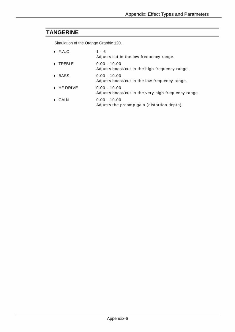
Appendix: Effect Types and Parameters
Appendix-6
TANGERINE
Simulation of the Orange Graphic 120.
F.A.C 1 - 6
Adjusts cut in the low frequency range.
TREBLE 0.00 - 10.00
Adjusts boost/cut in the high frequency range.
BASS 0.00 - 10.00
Adjusts boost/cut in the low frequency range.
HF DRIVE 0.00 - 10.00
Adjusts boost/cut in the very high frequency range.
GAIN 0.00 - 10.00
Adjusts the preamp gain (distortion depth).

Appendix: Effect Types and Parameters
Appendix-7
Bass Amplifier
CLASSIC AMP
Simulation of the Ampeg SVT.
GAIN 0.00 - 10.00
Adjusts the preamp gain (distortion depth).
ULTRA HIGH ON/OFF
Enriches the high frequency range when turned on.
ULTRA LOW ON/OFF
Enriches the low frequency range when turned on.
BASS 0.00 - 10.00
Adjusts boost/cut in the low frequency range.
MID RANGE 0.00 - 10.00
Adjusts boost/cut in the middle frequency range.
FREQUENCY 220Hz/450Hz/800Hz/1600Hz/3000Hz
Selects the target frequency of the MID RANGE parameter.
TREBLE 0.00 - 10.00
Adjusts boost/cut in the high frequency range.
MASTER 0.00 - 10.00
Adjusts the signal level after the process.
100BASSMAN
Simulation of the Fender Bassman 100.
DEEP ON/OFF
Enriches the low frequency range when turned on.
VOLUME 1.00 - 10.00
Adjusts the preamp gain (distortion depth).
TREBLE 1.00 - 10.00
Adjusts boost/cut in the high frequency range.
BASS 1.00 - 10.00
Adjusts boost/cut in the low frequency range.
MASTER 1.00 - 10.00
Adjusts the signal level after the process.
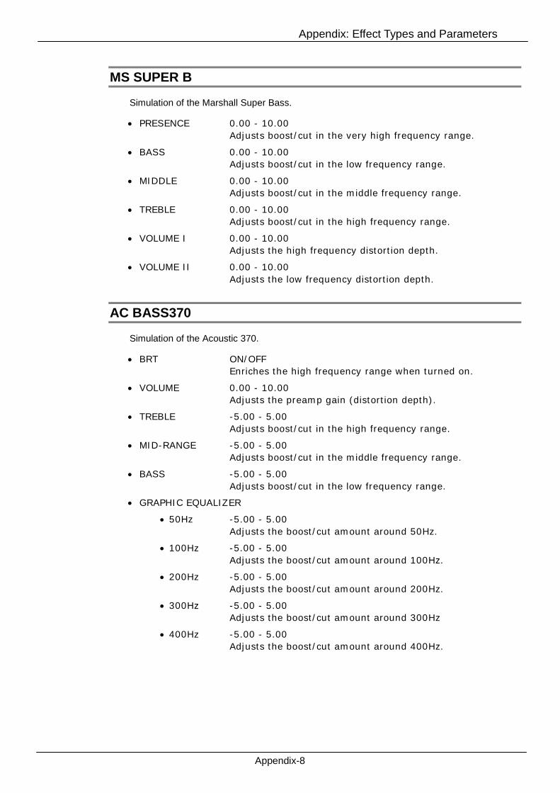
Appendix: Effect Types and Parameters
Appendix-8
MS SUPER B
Simulation of the Marshall Super Bass.
PRESENCE 0.00 - 10.00
Adjusts boost/cut in the very high frequency range.
BASS 0.00 - 10.00
Adjusts boost/cut in the low frequency range.
MIDDLE 0.00 - 10.00
Adjusts boost/cut in the middle frequency range.
TREBLE 0.00 - 10.00
Adjusts boost/cut in the high frequency range.
VOLUME I 0.00 - 10.00
Adjusts the high frequency distortion depth.
VOLUME II 0.00 - 10.00
Adjusts the low frequency distortion depth.
AC BASS370
Simulation of the Acoustic 370.
BRT ON/OFF
Enriches the high frequency range when turned on.
VOLUME 0.00 - 10.00
Adjusts the preamp gain (distortion depth).
TREBLE -5.00 - 5.00
Adjusts boost/cut in the high frequency range.
MID-RANGE -5.00 - 5.00
Adjusts boost/cut in the middle frequency range.
BASS -5.00 - 5.00
Adjusts boost/cut in the low frequency range.
GRAPHIC EQUALIZER
50Hz -5.00 - 5.00
Adjusts the boost/cut amount around 50Hz.
100Hz -5.00 - 5.00
Adjusts the boost/cut amount around 100Hz.
200Hz -5.00 - 5.00
Adjusts the boost/cut amount around 200Hz.
300Hz -5.00 - 5.00
Adjusts the boost/cut amount around 300Hz
400Hz -5.00 - 5.00
Adjusts the boost/cut amount around 400Hz.

Appendix: Effect Types and Parameters
Appendix-9
HRT3500
Simulation of the Hartke HA3500.
TUBE 0.00 - 10.00
Adjusts the mix level through the simulated tube amplifier.
SOLID STATE 0.00 - 10.00
Adjusts the mix level through the simulated solid-state circuit.
COMP OFF/ 0.00 – Inf
Adjusts the sensitivity of the compressor.
IN/OUT IN(ON)/OUT(OFF)
Sets ON/OFF the GRAPHIC EQUALIZER.
GRAPHIC EQUALIZER
30Hz -15.00dB - 15.00dB
Adjusts the boost/cut amount around 30Hz.
64Hz -15.00dB - 15.00dB
Adjusts the boost/cut amount around 64Hz.
125Hz -15.00dB - 15.00dB
Adjusts the boost/cut amount around 125Hz.
250Hz -15.00dB - 15.00dB
Adjusts the boost/cut amount around 250Hz.
500Hz -15.00dB - 15.00dB
Adjusts the boost/cut amount around 500Hz.
1kHz -15.00dB - 15.00dB
Adjusts the boost/cut amount around 1kHz.
2kHz -15.00dB - 15.00dB
Adjusts the boost/cut amount around 2kHz.
3kHz -15.00dB - 15.00dB
Adjusts the boost/cut amount around 3kHz.
5kHz -15.00dB - 15.00dB
Adjusts the boost/cut amount around 5kHz.
8kHz -15.00dB - 15.00dB
Adjusts the boost/cut amount around 8kHz.
CONTOUR LOW PASS -18.00 - 18.00
Equalizes the low frequency range widely.
CONTOUR HIGH PASS -18.00 - 18.00
Equalizes the high frequency range widely.
MASTER VOLUME 0.00 - 10.00
Adjusts the signal level after the process.

Appendix: Effect Types and Parameters
Appendix-10
Cabinet
Common Parameter
DISTANCE 0.00-10.00
Reverberates the sound as the cabinet gets farther.
BRIGHT COMBO 2x12
Simulation of the 2x12" Fender TwinReverb '65 cabinet.
JAZZ COMBO 2x12
Simulation of the 2x12" Roland JC-120 cabinet.
MS CRUNCH STACK 4x12
Simulation of the 4x12" Marshall 1960A.
MB DUAL STACK 4x12
Simulation of the 4x12" Mesa/Boogie Recto Standard Armor.
UK30 COMBO 2x12
Simulation of the 2x12" Vox AC30TBX cabinet.
PV STACK 4x12
Simulation of the 4x12" Peavey 5150SL.
B/M COMBO 4x10
Simulation of the 4x10" Fender Bassman cabinet.
HC100 STACK 4x12
Simulation of the 4x12" Hiwatt SE-4123.
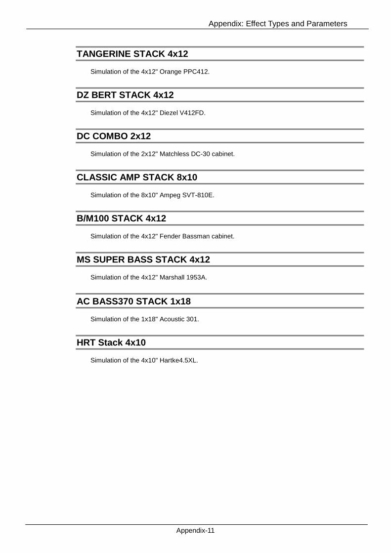
Appendix: Effect Types and Parameters
Appendix-11
TANGERINE STACK 4x12
Simulation of the 4x12" Orange PPC412.
DZ BERT STACK 4x12
Simulation of the 4x12" Diezel V412FD.
DC COMBO 2x12
Simulation of the 2x12" Matchless DC-30 cabinet.
CLASSIC AMP STACK 8x10
Simulation of the 8x10" Ampeg SVT-810E.
B/M100 STACK 4x12
Simulation of the 4x12" Fender Bassman cabinet.
MS SUPER BASS STACK 4x12
Simulation of the 4x12" Marshall 1953A.
AC BASS370 STACK 1x18
Simulation of the 1x18" Acoustic 301.
HRT Stack 4x10
Simulation of the 4x10" Hartke4.5XL.
Appendix: Effect Types and Parameters
Appendix-12
Mic
Common Parameter
POSITION L10.00 – C10.00 – R10.00
Adjusts the microphone position.
DYNAMIC57
Simulation of the Shure SM57.
CONDENSER414
Simulation of the AKG C414.
DYNAMIC421
Simulation of the Sennheiser MD421.
CONDENSER87
Simulation of the Neumann U 87.
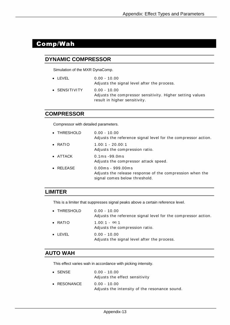
Appendix: Effect Types and Parameters
Appendix-13
Comp/Wah
DYNAMIC COMPRESSOR
Simulation of the MXR DynaComp.
LEVEL 0.00 - 10.00
Adjusts the signal level after the process.
SENSITIVITY 0.00 - 10.00
Adjusts the compressor sensitivity. Higher setting values
result in higher sensitivity.
COMPRESSOR
Compressor with detailed parameters.
THRESHOLD 0.00 - 10.00
Adjusts the reference signal level for the compressor action.
RATIO 1.00:1 - 20.00:1
Adjusts the compression ratio.
ATTACK 0.1ms -99.0ms
Adjusts the compressor attack speed.
RELEASE 0.00ms - 999.00ms
Adjusts the release response of the compression when the
signal comes below threshold.
LIMITER
This is a limiter that suppresses signal peaks above a certain reference level.
THRESHOLD 0.00 - 10.00
Adjusts the reference signal level for the compressor action.
RATIO 1.00:1 - ∞:1
Adjusts the compression ratio.
LEVEL 0.00 - 10.00
Adjusts the signal level after the process.
AUTO WAH
This effect varies wah in accordance with picking intensity.
SENSE 0.00 - 10.00
Adjusts the effect sensitivity
RESONANCE 0.00 - 10.00
Adjusts the intensity of the resonance sound.
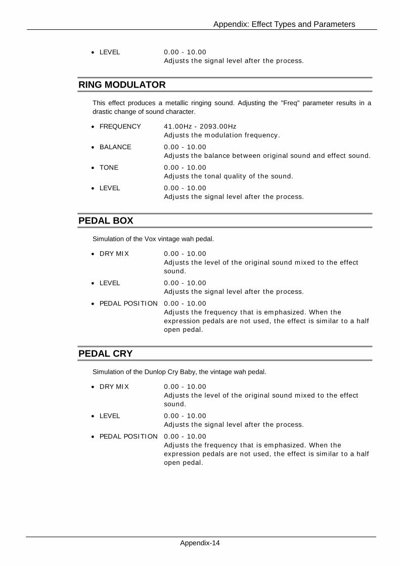
Appendix: Effect Types and Parameters
Appendix-14
LEVEL 0.00 - 10.00
Adjusts the signal level after the process.
RING MODULATOR
This effect produces a metallic ringing sound. Adjusting the "Freq" parameter results in a
drastic change of sound character.
FREQUENCY 41.00Hz - 2093.00Hz
Adjusts the modulation frequency.
BALANCE 0.00 - 10.00
Adjusts the balance between original sound and effect sound.
TONE 0.00 - 10.00
Adjusts the tonal quality of the sound.
LEVEL 0.00 - 10.00
Adjusts the signal level after the process.
PEDAL BOX
Simulation of the Vox vintage wah pedal.
DRY MIX 0.00 - 10.00
Adjusts the level of the original sound mixed to the effect
sound.
LEVEL 0.00 - 10.00
Adjusts the signal level after the process.
PEDAL POSITION 0.00 - 10.00
Adjusts the frequency that is emphasized. When the
expression pedals are not used, the effect is similar to a half
open pedal.
PEDAL CRY
Simulation of the Dunlop Cry Baby, the vintage wah pedal.
DRY MIX 0.00 - 10.00
Adjusts the level of the original sound mixed to the effect
sound.
LEVEL 0.00 - 10.00
Adjusts the signal level after the process.
PEDAL POSITION 0.00 - 10.00
Adjusts the frequency that is emphasized. When the
expression pedals are not used, the effect is similar to a half
open pedal.

Appendix: Effect Types and Parameters
Appendix-15
Distortion
OVER DRIVEN
Simulation of the Boss OD-1.
LEVEL 0.00-10.00
Adjusts the signal level after the process.
DRIVE 0.00-10.00
Adjusts the preamp gain (distortion depth).
TUBE SCREAMEN
Simulation of the Ibanez TS808.
OVERDRIVE 0.00 - 10.00
Adjusts the preamp gain (distortion depth).
TONE 0.00 - 10.00
Adjusts the tonal quality of the sound.
LEVEL 0.00 - 10.00
Adjusts the signal level after the process.
THE GOVERNOR
Simulation of the Marshall The Guv'nor.
GAIN 0.00 - 10.00
Adjusts the preamp gain (distortion depth).
BASS 0.00 - 10.00
Adjusts boost/cut in the low frequency range.
MIDDLE 0.00 - 10.00
Adjusts boost/cut in the middle frequency range.
TREBLE 0.00 - 10.00
Adjusts boost/cut in the high frequency range.
LEVEL 0.00 - 10.00
Adjusts the signal level after the process.
SQUEAK
Simulation of the Pro Co Rat.
DISTORTION 0.00 - 10.00
Adjusts the preamp gain (distortion depth).

Appendix: Effect Types and Parameters
Appendix-16
FILTER 0.00 - 10.00
Adjusts the tonal quality of the sound.
VOLUME 0.00 - 10.00
Adjusts the signal level after the process.
FUZZ SMILE
Simulation of the Dunlop Dallas Arbiter Fuzz Face.
VOLUME 0.00 - 10.00
Adjusts the signal level after the process.
FUZZ 0.00 - 10.00
Adjusts the preamp gain (distortion depth).
+DISTORTION
Simulation of the MXR Distortion+.
OUTPUT 0.00 - 10.00
Adjusts the signal level after the process.
DISTORION 0.00 - 10.00
Adjusts the preamp gain (distortion depth).
GREAT MUFF
Simulation of the Electro-Harmonix Big Muff.
VOLUME 0.00 - 10.00
Adjusts the signal level after the process.
TONE 0.00 - 10.00
Adjusts the tonal quality of the sound.
SUSTAIN 0.00 - 10.00
Adjusts the preamp gain (distortion depth).
METAL WORLD
Simulation of the Boss Metal Zone MT-2.
LEVEL 0.00 - 10.00
Adjusts the signal level after the process.
LOW -15.00dB - 15.00dB
Adjusts boost/cut in the low frequency range.
HIGH -15.00dB - 15.00dB
Adjusts boost/cut in the high frequency range.
MID FREQUENCY 200.00Hz - 5000.00Hz
Selects the target frequency of the MIDDLE parameter.
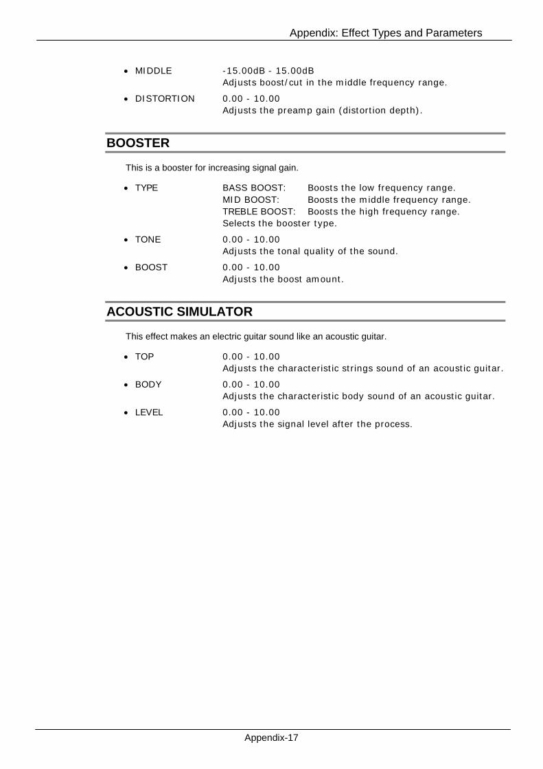
Appendix: Effect Types and Parameters
Appendix-17
MIDDLE -15.00dB - 15.00dB
Adjusts boost/cut in the middle frequency range.
DISTORTION 0.00 - 10.00
Adjusts the preamp gain (distortion depth).
BOOSTER
This is a booster for increasing signal gain.
TYPE BASS BOOST: Boosts the low frequency range.
MID BOOST: Boosts the middle frequency range.
TREBLE BOOST: Boosts the high frequency range.
Selects the booster type.
TONE 0.00 - 10.00
Adjusts the tonal quality of the sound.
BOOST 0.00 - 10.00
Adjusts the boost amount.
ACOUSTIC SIMULATOR
This effect makes an electric guitar sound like an acoustic guitar.
TOP 0.00 - 10.00
Adjusts the characteristic strings sound of an acoustic guitar.
BODY 0.00 - 10.00
Adjusts the characteristic body sound of an acoustic guitar.
LEVEL 0.00 - 10.00
Adjusts the signal level after the process.

Appendix: Effect Types and Parameters
Appendix-18
Modulation
CHORUS
This effect mixes a variable pitch-shifted component to the original signal, resulting in
full-bodied resonating sound.
DEPTH 0.00 - 10.00
Adjusts the effect depth.
RATE 0.10Hz - 5.10Hz
Adjusts the modulation rate.
TONE 0.00 - 10.00
Adjusts the tonal quality of the sound.
MIX 0.00 - 10.00
Adjusts the level of the effect sound mixed to the original
sound.
ENSEMBLE
This is a chorus ensemble with three-dimensional movement.
DEPTH 0.00 - 10.00
Adjusts the effect depth.
RATE 0.10Hz - 10.00Hz
Adjusts the modulation rate.
MIX 0.00 - 10.00
Adjusts the level of the effect sound mixed to the original
sound.
CHORUS VIBRATO
Simulation of the Boss CE-1.
LEVEL CONTROL 0.00 - 10.00
Adjusts the signal level before the process.
CHORUS INTENSITY 0.00 - 10.00
Adjusts the chorus intensity.
DEPTH (FOR VIBRATO) 0.00 - 10.00
Adjusts the effect depth.
RATE (FOR VIBRATO) 2.86Hz - 10.82Hz
Adjusts the modulation rate.
VIBRATO CHORUS Chorus/Vibrato
Switches the effect between chorus and vibrato.

Appendix: Effect Types and Parameters
Appendix-19
TREMOLO
This effect periodically varies the volume level.
DEPTH 0.00 - 10.00
Adjusts the effect depth.
RATE 0.50Hz - 19.50Hz
Adjusts the modulation rate.
LFO CLIP 0.00 - 10.00
Emphasises the effect by clipping the peaks.
WAVE TRAIANGLE (triangle wave) /SAW (saw wave) /RV.SAW
(reversed saw wave)
Selects the modulation wave from above.
BPM SYNC ON/OFF
Synchronizes to BPM in accordance with SYNC PATTERN
parameter, when turned on.
SYNC PATTERN See Table 1.
TAP Sets the modulation rate through the tapping interval.
FLANGER
This effect produces a resonating and strongly undulating sound.
DEPTH 0.00-10.00
Adjusts the effect depth.
RATE 0.04Hz - 15.00Hz
Adjusts the modulation rate.
Manual 0.00-10.00
Adjusts the frequency range on which the effect operates.
RESONANCE 0.00-10.00
Adjusts the resonance intensity.
Table 1
Image Detail Image Detail
Thirty-second note Dotted eighth note
Sixteenth note Quarter note
3Quarter triplet note Dotted quarter note
Dotted sixteenth note×2
Quarter note x 2
Eighth note :
3Half triplet note
×20Quarter note x 20
* For the delay effects, sixteenth note and further is available.

Appendix: Effect Types and Parameters
Appendix-20
INVERT ON/OFF
Inverts the polarity of the feedback.
BPM SYNC ON/OFF
Synchronizes to BPM in accordance with SYNC PATTERN
parameter, when turned on.
SYNC PATTERN See table 1 (Appendix-19).
TAP Sets the modulation rate through the tapping interval.
PHASER
This effect produces a swooshing sound.
RATE 0.10Hz - 8.50Hz
Adjusts the modulation rate.
COLOR 4STAGE/4STAGE INV/8STAGE/8STAGE INV
Adjusts the sound color.
BPM SYNC ON/OFF
Synchronizes to BPM in accordance with SYNC PATTERN
parameter, when turned on.
SYNC PATTERN See table 1 (Appendix-19).
TAP Sets the modulation rate through the tapping interval.
OCTAVE
This effect mixes the sound 1 and 2 octave below.
1 OCT LEVEL 0.00 -10.00
Adjusts the level of the one octave lower sound component.
2 OCT LEVEL 0.00 -10.00
Adjusts the level of the two octave lower sound component.
DRY LEVEL 0.00 -10.00
Adjusts the level of the original sound.
CRY
This effect varies the sound like a talking modulator.
SENSE 0.00 - 10.00
Adjusts the effect sensitivity.
RESONANCE 0.00 - 10.00
Adjusts the resonance intensity.
RANGE 0.00 - 10.00
Adjusts the frequency range processed by the effect.
BALANCE 0.00 - 10.00
Adjusts the balance between original sound and effect sound.
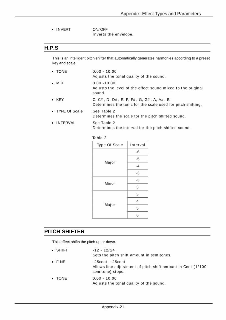
Appendix: Effect Types and Parameters
INVERT ON/OFF
Inverts the envelope.
H.P.S
This is an intelligent pitch shifter that automatically generates harmonies according to a preset
key and scale.
TONE 0.00 - 10.00
Adjusts the tonal quality of the sound.
MIX 0.00 -10.00
Adjusts the level of the effect sound mixed to the original
sound.
KEY C, C#, D, D#, E, F, F#, G, G#, A, A#, B
Determines the tonic for the scale used for pitch shifting.
TYPE Of Scale See Table 2
Determines the scale for the pitch shifted sound.
INTERVAL See Table 2
Determines the interval for the pitch shifted sound.
PITCH SHIFTER
This effect shifts th
SHIFT
FINE
TONE
Table 2
Type Of Scale Interval
-6
-5
-4Major
-3
-3Minor
3
3
4
5Major
Appendix-21
e pitch up or down.
-12 - 12/24
Sets the pitch shift amount in semitones.
-25cent – 25cent
Allows fine adjustment of pitch shift amount in Cent (1/100
semitone) steps.
0.00 - 10.00
Adjusts the tonal quality of the sound.
6

Appendix: Effect Types and Parameters
Appendix-22
BALANCE 0.00 – 10.00
Adjusts the balance between original sound and effect sound.
MONO PITCH
This is a pitch shifter specifically for monophonic sound (single-note playing), with little sound
fluctuation.
SHIFT -12 - 12 / 24
Adjusts the pitch shift amount in semitones.
FINE -25cent – 25cent
Allows fine adjustment of pitch shift amount in Cent (1/100
semitone) steps.
TONE 0.00 - 10.00
Adjusts the tonal quality of the sound.
BALANCE 0.00 - 10.00
Adjusts the balance between original sound and effect sound.
PEDAL PITCH
This effect allows using a pedal to shift the pitch in real time.
TONE 0.00 - 10.00
Adjusts the tonal quality of the sound.
COLOR See Table 1 (Appendix-22)
Selects the type of pitch change caused by the pedal.
PEDAL POSITION 0.00 - 10.00
Sets the pitch shift amount. Depending on the "Color" setting,
the balance between original sound and effect sound also
changes accordingly.
PEDAL MONO PITCH
This is a pitch shifter specifically for monophonic sound (single-note playing), which allows the
pitch to be shifted in real time with an expression pedal.
TONE 0.00 - 10.00
Adjusts the tonal quality of the sound.
COLOR See Table 3
Selects the type of pitch change caused by the pedal.
PEDAL POSITION 0.00 - 10.00
Sets the pitch shift amount. Depending on the "Color" setting,
the balance between original sound and effect sound also
changes accordingly.
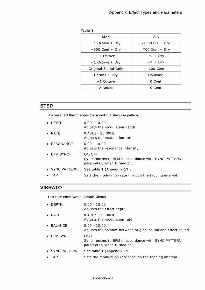
Appendix: Effect Types and Parameters
STEP
Special effect tha
DEPTH
RATE
RESONANCE
BPM SYNC
SYNC PATTER
TAP
VIBRATO
This is an effect w
DEPTH
RATE
BALANCE
BPM SYNC
SYNC PATTER
TAP
Table 3
MAX MIN
+1 Octave + Dry -1 Octave + Dry
+500 Cent + Dry -700 Cent + Dry
+1 Octave -∞ + Dry
+1 Octave + Dry -∞ + Dry
Original Sound Only -100 Cent
Detune + Dry Doubling
+1 Octave 0 Cent
-2 Octave 0 Cent
Appendix-23
t changes the sound in a staircase pattern.
0.00 - 10.00
Adjusts the modulation depth.
0.40Hz - 20.00Hz
Adjusts the modulation rate.
0.00 - 10.00
Adjusts the resonance intensity.
ON/OFF
Synchronizes to BPM in accordance with SYNC PATTERN
parameter, when turned on.
N See table 1 (Appendix-19).
Sets the modulation rate through the tapping interval.
ith automatic vibrato.
0.00 - 10.00
Adjusts the effect depth.
0.40Hz - 10.00Hz
Adjusts the modulation rate.
0.00 - 10.00
Adjusts the balance between original sound and effect sound.
ON/OFF
Synchronizes to BPM in accordance with SYNC PATTERN
parameter, when turned on.
N See table 1 (Appendix-19).
Sets the modulation rate through the tapping interval.
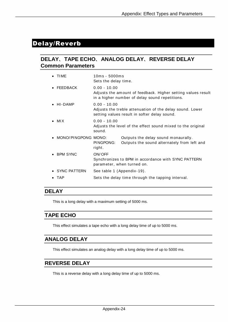
Appendix: Effect Types and Parameters
Appendix-24
Delay/Reverb
DELAY、TAPE ECHO、ANALOG DELAY、REVERSE DELAYCommon Parameters
TIME 10ms - 5000ms
Sets the delay time.
FEEDBACK 0.00 - 10.00
Adjusts the amount of feedback. Higher setting values result
in a higher number of delay sound repetitions.
HI-DAMP 0.00 - 10.00
Adjusts the treble attenuation of the delay sound. Lower
setting values result in softer delay sound.
MIX 0.00 - 10.00
Adjusts the level of the effect sound mixed to the original
sound.
MONO/PINGPONG MONO: Outputs the delay sound monaurally.
PINGPONG: Outputs the sound alternately from left and
right.
BPM SYNC ON/OFF
Synchronizes to BPM in accordance with SYNC PATTERN
parameter, when turned on.
SYNC PATTERN See table 1 (Appendix-19).
TAP Sets the delay time through the tapping interval.
DELAY
This is a long delay with a maximum setting of 5000 ms.
TAPE ECHO
This effect simulates a tape echo with a long delay time of up to 5000 ms.
ANALOG DELAY
This effect simulates an analog delay with a long delay time of up to 5000 ms.
REVERSE DELAY
This is a reverse delay with a long delay time of up to 5000 ms.
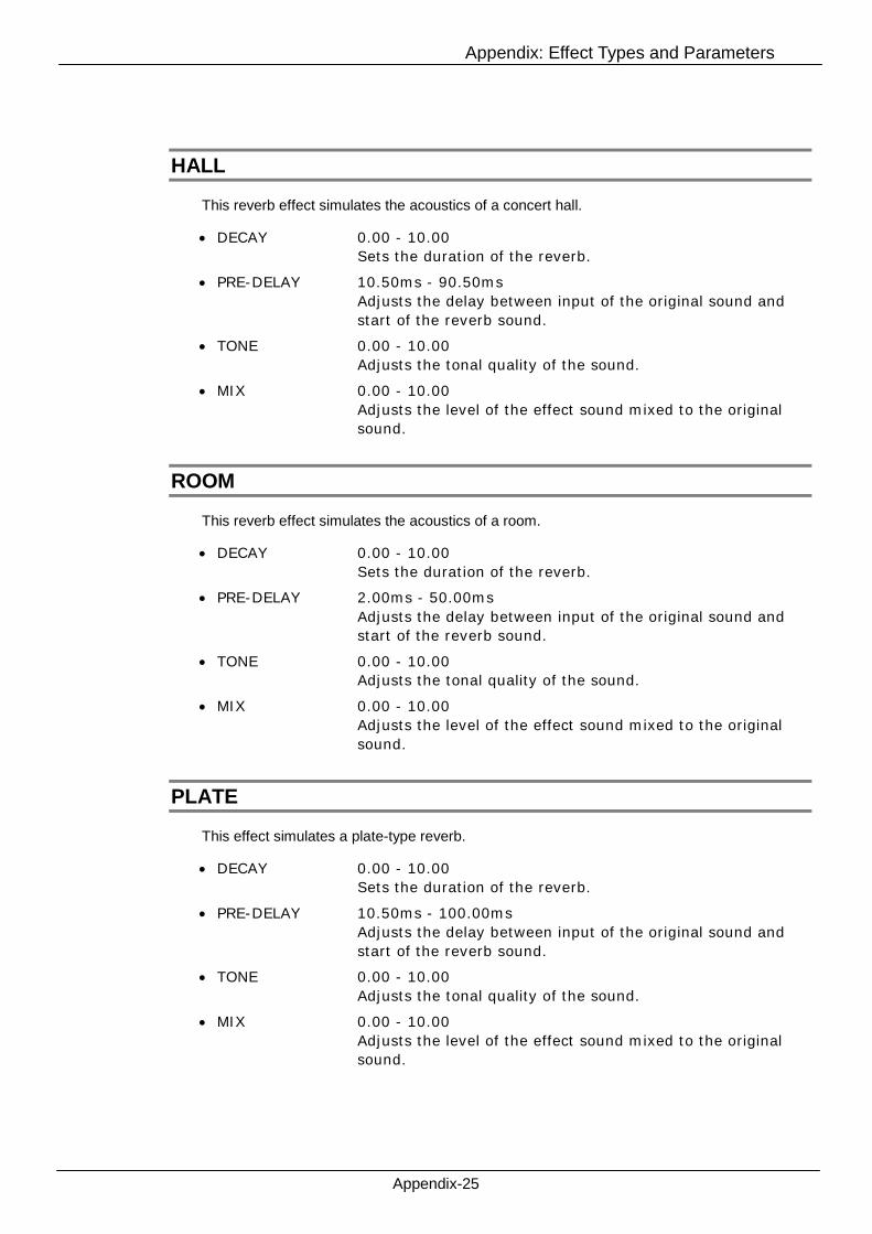
Appendix: Effect Types and Parameters
Appendix-25
HALL
This reverb effect simulates the acoustics of a concert hall.
DECAY 0.00 - 10.00
Sets the duration of the reverb.
PRE-DELAY 10.50ms - 90.50ms
Adjusts the delay between input of the original sound and
start of the reverb sound.
TONE 0.00 - 10.00
Adjusts the tonal quality of the sound.
MIX 0.00 - 10.00
Adjusts the level of the effect sound mixed to the original
sound.
ROOM
This reverb effect simulates the acoustics of a room.
DECAY 0.00 - 10.00
Sets the duration of the reverb.
PRE-DELAY 2.00ms - 50.00ms
Adjusts the delay between input of the original sound and
start of the reverb sound.
TONE 0.00 - 10.00
Adjusts the tonal quality of the sound.
MIX 0.00 - 10.00
Adjusts the level of the effect sound mixed to the original
sound.
PLATE
This effect simulates a plate-type reverb.
DECAY 0.00 - 10.00
Sets the duration of the reverb.
PRE-DELAY 10.50ms - 100.00ms
Adjusts the delay between input of the original sound and
start of the reverb sound.
TONE 0.00 - 10.00
Adjusts the tonal quality of the sound.
MIX 0.00 - 10.00
Adjusts the level of the effect sound mixed to the original
sound.

Appendix: Effect Types and Parameters
Appendix-26
SPRING
This effect simulates a spring-type reverb.
DECAY 0.00 - 10.00
Sets the duration of the reverb.
MIX 0.00 - 10.00
Adjusts the level of the effect sound mixed to the original
sound.
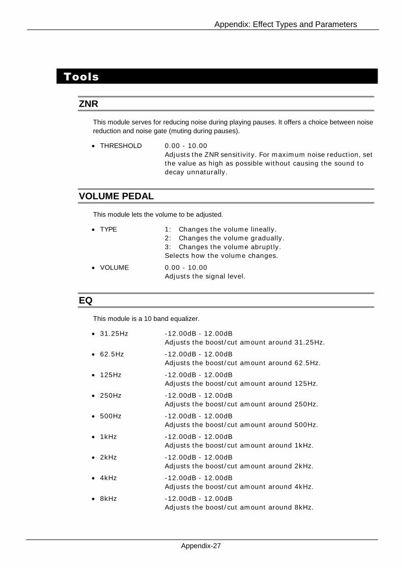
Appendix: Effect Types and Parameters
Appendix-27
Tools
ZNR
This module serves for reducing noise during playing pauses. It offers a choice between noise
reduction and noise gate (muting during pauses).
THRESHOLD 0.00 - 10.00
Adjusts the ZNR sensitivity. For maximum noise reduction, set
the value as high as possible without causing the sound to
decay unnaturally.
VOLUME PEDAL
This module lets the volume to be adjusted.
TYPE 1: Changes the volume lineally.
2: Changes the volume gradually.
3: Changes the volume abruptly.
Selects how the volume changes.
VOLUME 0.00 - 10.00
Adjusts the signal level.
EQ
This module is a 10 band equalizer.
31.25Hz -12.00dB - 12.00dB
Adjusts the boost/cut amount around 31.25Hz.
62.5Hz -12.00dB - 12.00dB
Adjusts the boost/cut amount around 62.5Hz.
125Hz -12.00dB - 12.00dB
Adjusts the boost/cut amount around 125Hz.
250Hz -12.00dB - 12.00dB
Adjusts the boost/cut amount around 250Hz.
500Hz -12.00dB - 12.00dB
Adjusts the boost/cut amount around 500Hz.
1kHz -12.00dB - 12.00dB
Adjusts the boost/cut amount around 1kHz.
2kHz -12.00dB - 12.00dB
Adjusts the boost/cut amount around 2kHz.
4kHz -12.00dB - 12.00dB
Adjusts the boost/cut amount around 4kHz.
8kHz -12.00dB - 12.00dB
Adjusts the boost/cut amount around 8kHz.

Appendix: Effect Types and Parameters
Appendix-28
16kHz -12.00dB - 12.00dB
Adjusts the boost/cut amount around 16kHz.
VOLUME -InfdB - 6.02dB
Adjusts the signal level after the process.
AMP MODULE
This module is for the addition amplifiers.
SPLITTER
This module splits the input signal into two.
MIXER
This module mixes two input signals.
LEVEL A -Inf dB - 6.02dB
Adjusts the input A level.
PAN A L100 - C0 - R100
Adjusts the input A panning.
LEVEL B -Inf dB - 6.02dB
Adjusts the input B level.
PAN B L100 - C0 - R100
Adjusts the input B panning.
ISOLATOR
This module splits the input signal at a certain frequency range.
FREQUENCY 0.00Hz – 11000.00Hz
Adjusts the frequency where the signal gets split.
Appendix: MIDI IMPLEMENTATION
Appendix-MIDI-1
USB Audio Interface S2t/C5.1t
MIDI IMPLEMENTATION
REVISION HISTORY;
Ver 1.00 20.February,2008 - First Issue
ZOOM Corporation TOKYO, JAPAN
Z4E-0034-A4P
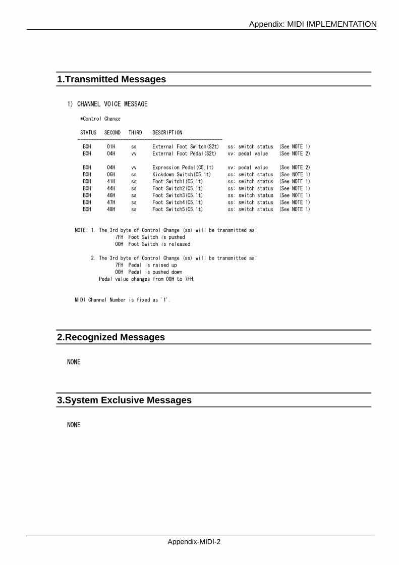
Appendix: MIDI IMPLEMENTATION
Appendix-MIDI-2
1.Transmitted Messages
1) CHANNEL VOICE MESSAGE
*Control Change
STATUS SECOND THIRD DESCRIPTION
------------------------------------------------------
B0H 01H ss External Foot Switch(S2t) ss: switch status (See NOTE 1)
B0H 04H vv External Foot Pedal(S2t) vv: pedal value (See NOTE 2)
B0H 04H vv Expression Pedal(C5.1t) vv: pedal value (See NOTE 2)
B0H 06H ss Kickdown Switch(C5.1t) ss: switch status (See NOTE 1)
B0H 41H ss Foot Switch1(C5.1t) ss: switch status (See NOTE 1)
B0H 44H ss Foot Switch2(C5.1t) ss: switch status (See NOTE 1)
B0H 46H ss Foot Switch3(C5.1t) ss: switch status (See NOTE 1)
B0H 47H ss Foot Switch4(C5.1t) ss: switch status (See NOTE 1)
B0H 48H ss Foot Switch5(C5.1t) ss: switch status (See NOTE 1)
NOTE: 1. The 3rd byte of Control Change (ss) will be transmitted as;
7FH Foot Switch is pushed
00H Foot Switch is released
2. The 3rd byte of Control Change (ss) will be transmitted as;
7FH Pedal is raised up
00H Pedal is pushed down
Pedal value changes from 00H to 7FH.
MIDI Channel Number is fixed as '1'.
2.Recognized Messages
NONE
3.System Exclusive Messages
NONE
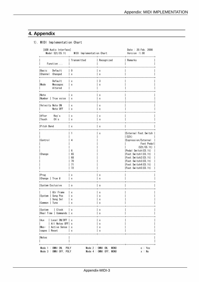
Appendix: MIDI IMPLEMENTATION
Appendix-MIDI-3
4. Appendix
1). MIDI Implementation Chart
[USB Audio Interface] Date : 20.Feb. 2008
Model S2t/C5.1t MIDI Implementation Chart Version :1.00
+---------------------+--------------------+--------------------+---------------------+
| | Transmitted | Recognized | Remarks |
| Function ... | | | |
+---------------------+--------------------+--------------------+---------------------+
|Basic Default | 0 | x | |
|Channel Changed | x | x | |
+---------------------+--------------------+--------------------+---------------------+
| Default | x | 3 | |
|Mode Messages | x | x | |
| Altered | | | |
+---------------------+--------------------+--------------------+---------------------+
|Note | x | x | |
|Number | True voice | x | x | |
+---------------------|--------------------|--------------------|---------------------|
|Velocity Note ON | x | x | |
| Note OFF | x | x | |
+---------------------+--------------------+--------------------+---------------------+
|After Key's | x | x | |
|Touch Ch's | x | x | |
+---------------------+--------------------+--------------------+---------------------+
|Pitch Bend | x | x | |
+---------------------+--------------------+--------------------+---------------------+
| | 1 | x |External Foot Switch |
| | | |(S2t) |
|Control | 4 | |Expression/External |
| | | | Foot Pedal|
| | | | (S2t/C5.1t) |
| | 6 | |Pedal Switch(C5.1t) |
|Change | 65 | |Foot Switch1(C5.1t) |
| | 68 | |Foot Switch2(C5.1t) |
| | 70 | |Foot Switch3(C5.1t) |
| | 71 | |Foot Switch4(C5.1t) |
| | 72 | |Foot Switch5(C5.1t) |
+---------------------+--------------------+--------------------+---------------------+
|Prog | x | x | |
|Change | True # | x | x | |
+---------------------+--------------------+--------------------+---------------------+
|System Exclusive | o | o | |
+---------------------+--------------------+--------------------+---------------------+
| | Qtr Frame | x | x | |
|System | Song Pos | x | x | |
| | Song Sel | x | x | |
|Common | Tune | x | x | |
+---------------------+--------------------+--------------------+---------------------+
|System | Clock | x | x | |
|Real Time | Commands | x | x | |
+---------------------+--------------------+--------------------+---------------------+
|Aux | Local ON/OFF | x | x | |
| | All Notes OFF| x | x | |
|Mes- | Active Sense | x | x | |
|sages | Reset | x | x | |
+---------------------+--------------------+--------------------+---------------------+
|Notes | |
| | |
+---------------------+--------------------+--------------------+---------------------+
Mode 1 : OMNI ON, POLY Mode 2 : OMNI ON, MONO o : Yes
Mode 3 : OMNI OFF, POLY Mode 4 : OMNI OFF, MONO x : No

©ZOOM Corporation2F, ITOHPIA Iwamotocho 2-chome Bldg., 2-11-2 Iwamoto-cho,Chiyoda-ku, Tokyo 101-0032, Japanhttp://www.zoom.co.jp
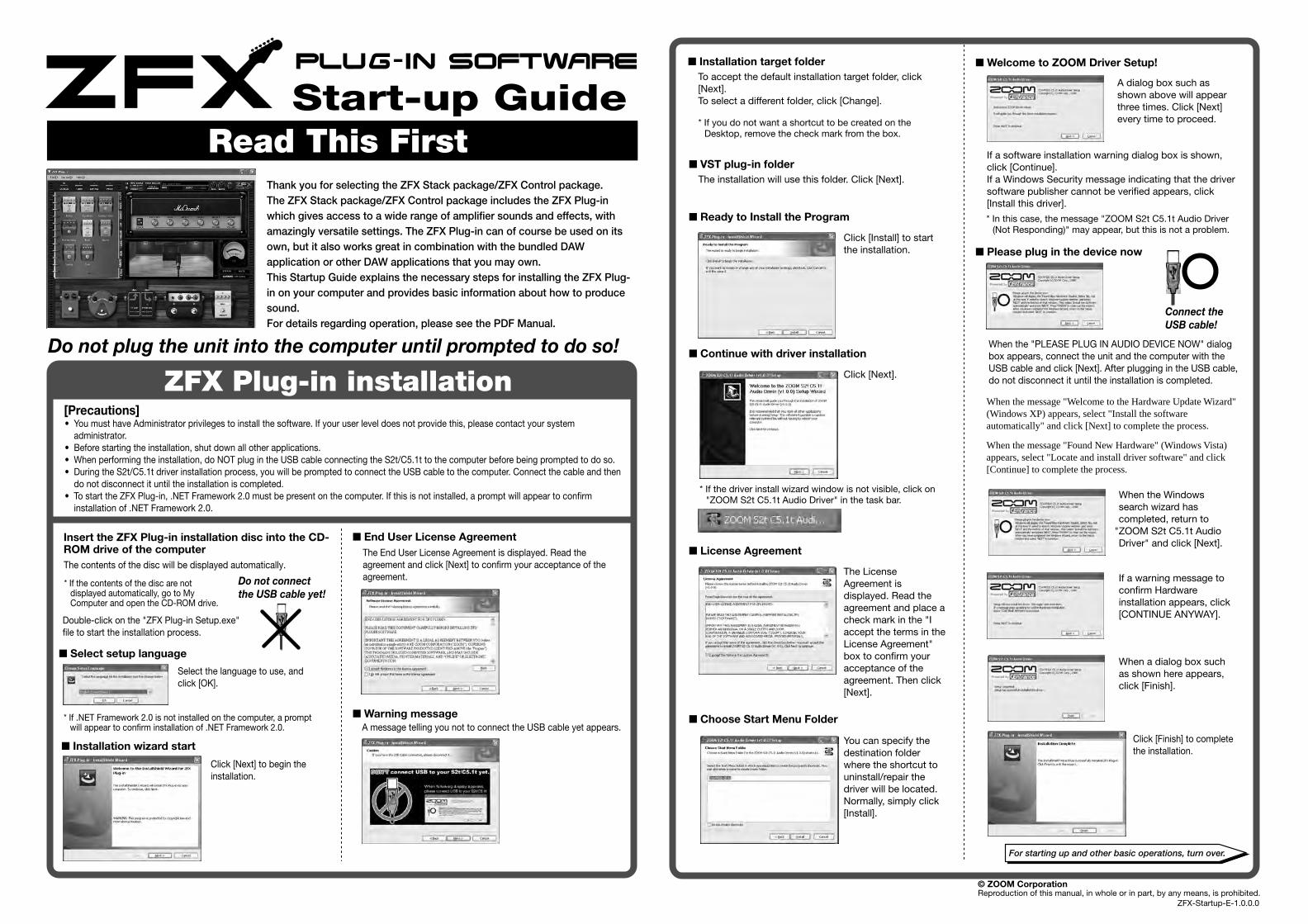
Read This First Start-up Guide
Do not plug the unit into the computer until prompted to do so!
ZFX Plug-in installation
Thank you for selecting the ZFX Stack package/ZFX Control package. The ZFX Stack package/ZFX Control package includes the ZFX Plug-in which gives access to a wide range of amplifier sounds and effects, with amazingly versatile settings. The ZFX Plug-in can of course be used on its own, but it also works great in combination with the bundled DAW application or other DAW applications that you may own. This Startup Guide explains the necessary steps for installing the ZFX Plug-in on your computer and provides basic information about how to produce sound. For details regarding operation, please see the PDF Manual.
© ZOOM CorporationReproduction of this manual, in whole or in part, by any means, is prohibited.
[Precautions]• You must have Administrator privileges to install the software. If your user level does not provide this, please contact your system
administrator. • Before starting the installation, shut down all other applications. • When performing the installation, do NOT plug in the USB cable connecting the S2t/C5.1t to the computer before being prompted to do so. • During the S2t/C5.1t driver installation process, you will be prompted to connect the USB cable to the computer. Connect the cable and then
do not disconnect it until the installation is completed. • To start the ZFX Plug-in, .NET Framework 2.0 must be present on the computer. If this is not installed, a prompt will appear to confirm
installation of .NET Framework 2.0.
Insert the ZFX Plug-in installation disc into the CD-ROM drive of the computer
Double-click on the "ZFX Plug-in Setup.exe" file to start the installation process.
Select the language to use, and click [OK].
* If the contents of the disc are not displayed automatically, go to My Computer and open the CD-ROM drive.
* If .NET Framework 2.0 is not installed on the computer, a prompt will appear to confirm installation of .NET Framework 2.0.
n Select setup language
Click [Next] to begin the installation.
n Installation wizard start
The End User License Agreement is displayed. Read the agreement and click [Next] to confirm your acceptance of the agreement.
n End User License Agreement
A message telling you not to connect the USB cable yet appears.n Warning message
The installation will use this folder. Click [Next].
n VST plug-in folder
n Ready to Install the Program
Click [Install] to start the installation.
n Welcome to ZOOM Driver Setup!
A dialog box such as shown above will appear three times. Click [Next] every time to proceed.
n Continue with driver installation
Click [Next].
n License Agreement
The License Agreement is displayed. Read the agreement and place a check mark in the "I accept the terms in the License Agreement" box to confirm your acceptance of the agreement. Then click [Next].
n Choose Start Menu Folder
You can specify the destination folder where the shortcut to uninstall/repair the driver will be located. Normally, simply click [Install].
n Please plug in the device now
When the Windows search wizard has completed, return to
"ZOOM S2t C5.1t Audio Driver" and click [Next].
If a warning message to confirm Hardware installation appears, click [CONTINUE ANYWAY].
When a dialog box such as shown here appears, click [Finish].
Click [Finish] to complete the installation.
If a software installation warning dialog box is shown, click [Continue].If a Windows Security message indicating that the driver software publisher cannot be verified appears, click [Install this driver].
When the message "Welcome to the Hardware Update Wizard" (Windows XP) appears, select "Install the software automatically" and click [Next] to complete the process.
When the message "Found New Hardware" (Windows Vista) appears, select "Locate and install driver software" and click [Continue] to complete the process.
When the "PLEASE PLUG IN AUDIO DEVICE NOW" dialog box appears, connect the unit and the computer with the USB cable and click [Next]. After plugging in the USB cable, do not disconnect it until the installation is completed.
* In this case, the message "ZOOM S2t C5.1t Audio Driver (Not Responding)" may appear, but this is not a problem.
* If the driver install wizard window is not visible, click on "ZOOM S2t C5.1t Audio Driver" in the task bar.
To accept the default installation target folder, click [Next].To select a different folder, click [Change].
n Installation target folder
* If you do not want a shortcut to be created on the Desktop, remove the check mark from the box.
The contents of the disc will be displayed automatically.
Connect the USB cable!
Do not connect the USB cable yet!
ZFX-Startup-E-1.0.0.0
For starting up and other basic operations, turn over.
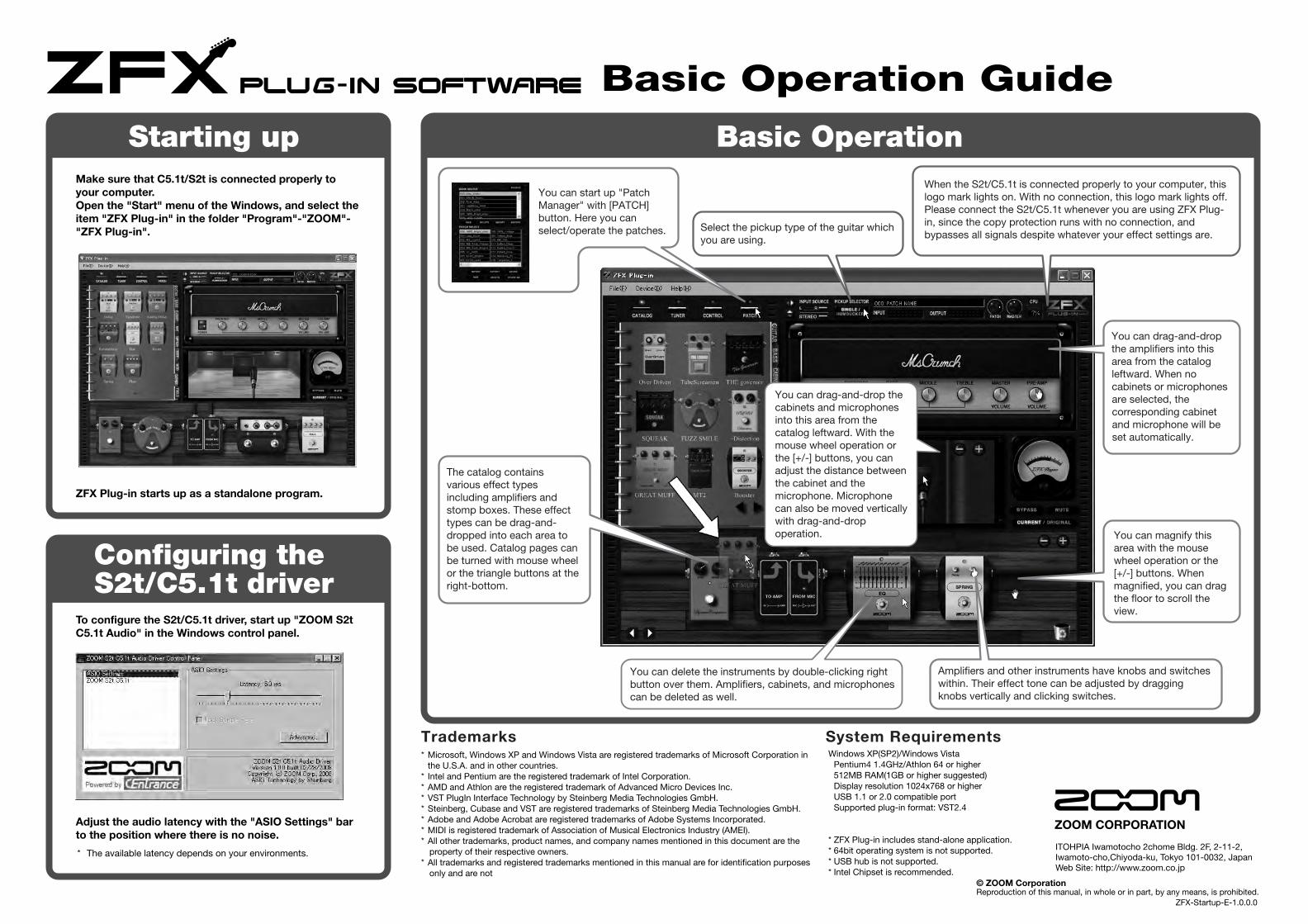
ZFX-Startup-E-1.0.0.0
* The available latency depends on your environments.
*Microsoft, Windows XP and Windows Vista are registered trademarks of Microsoft Corporation in the U.S.A. and in other countries.
* Intel and Pentium are the registered trademark of Intel Corporation.*AMD and Athlon are the registered trademark of Advanced Micro Devices Inc.*VST PlugIn Interface Technology by Steinberg Media Technologies GmbH.*Steinberg, Cubase and VST are registered trademarks of Steinberg Media Technologies GmbH.*Adobe and Adobe Acrobat are registered trademarks of Adobe Systems Incorporated.*MIDI is registered trademark of Association of Musical Electronics Industry (AMEI).*All other trademarks, product names, and company names mentioned in this document are the
property of their respective owners.*All trademarks and registered trademarks mentioned in this manual are for identification purposes
only and are not
Windows XP(SP2)/Windows Vista Pentium4 1.4GHz/Athlon 64 or higher 512MB RAM(1GB or higher suggested) Display resolution 1024x768 or higher USB 1.1 or 2.0 compatible port Supported plug-in format: VST2.4
*ZFX Plug-in includes stand-alone application.*64bit operating system is not supported.*USB hub is not supported.*Intel Chipset is recommended.
Make sure that C5.1t/S2t is connected properly to your computer. Open the "Start" menu of the Windows, and select the item "ZFX Plug-in" in the folder "Program"-"ZOOM"-"ZFX Plug-in".
ZFX Plug-in starts up as a standalone program.
Starting up Basic Operation
To configure the S2t/C5.1t driver, start up "ZOOM S2t C5.1t Audio" in the Windows control panel.
Adjust the audio latency with the "ASIO Settings" bar to the position where there is no noise.
Configuring the S2t/C5.1t driver
Basic Operation Guide
System RequirementsTrademarks
ITOHPIA Iwamotocho 2chome Bldg. 2F, 2-11-2, Iwamoto-cho,Chiyoda-ku, Tokyo 101-0032, JapanWeb Site: http://www.zoom.co.jp
ZOOM CORPORATION
© ZOOM CorporationReproduction of this manual, in whole or in part, by any means, is prohibited.
You can start up "Patch Manager" with [PATCH] button. Here you can select/operate the patches. Select the pickup type of the guitar which
you are using.
When the S2t/C5.1t is connected properly to your computer, this logo mark lights on. With no connection, this logo mark lights off. Please connect the S2t/C5.1t whenever you are using ZFX Plug-in, since the copy protection runs with no connection, and bypasses all signals despite whatever your effect settings are.
You can drag-and-drop the amplifiers into this area from the catalog leftward. When no cabinets or microphones are selected, the corresponding cabinet and microphone will be set automatically.
You can drag-and-drop the cabinets and microphones into this area from the catalog leftward. With the mouse wheel operation or the [+/-] buttons, you can adjust the distance between the cabinet and the microphone. Microphone can also be moved vertically with drag-and-drop operation.
You can delete the instruments by double-clicking right button over them. Amplifiers, cabinets, and microphones can be deleted as well.
Amplifiers and other instruments have knobs and switches within. Their effect tone can be adjusted by dragging knobs vertically and clicking switches.
You can magnify this area with the mouse wheel operation or the [+/-] buttons. When magnified, you can drag the floor to scroll the view.
The catalog contains various effect types including amplifiers and stomp boxes. These effect types can be drag-and-dropped into each area to be used. Catalog pages can be turned with mouse wheel or the triangle buttons at the right-bottom.

© ZOOM Corporation Reproduction of this manual, in whole or in part, by any means, is prohibited.
ZFX-Hardware-E-1
l Number of Audio Record/ Record: 1 pair of stereo Playback Channels Playback: 1 pair of stereol Audio Sampling 24bit 48kHz/44.1kHzl Frequency Response 48 kHz: 20 Hz to 22 kHz (+0 dB/-1 dB) 44.1 kHz: 20 Hz to 20 kHz (+0 dB/-0.5 dB)l USB TypeB USB 1.1 Full Speedl Inputs •Hi-z Input Standard mono phone jack Input impedance: 470 kiloohm Input level: -17dBm to +4dBm •MIC Input XLR/standard phone combo jack x2 (pin 2:HOT, Tip:HOT, Ring:COLD, Sleeve:GND) (Balanced and Unbalanced operation) Input impedance: 1 kiloohm or more Input level: -38dBm to +1dBm •LINE INPUT Standard mono phone jack(L/R) Input impedance: 47 kiloohm Rated input level: -10dBm •AUX Input Mini phone jack (stereo) Input impedance: 15 kiloohm Rated input level: -10dBm
l Phantom powersupply 48Vl Outputs •Line Output Standard mono phone jack (L/R) Output impedance: 5 kiloohm or less Rated output level:-10dBm •Headphone Standard phone jack (stereo) Output impedance: 10 ohm Rated output 20mW (32 ohm load)l Residual Noise Level Output Jack: -96 dBm (Input short, At the unity gain, IHF-A typ.)l Control input (S2t only) •FOOT SW For FS01 •CONTROL IN For FP02/FP01l Tube circuitry 12AX7l Power requirements USB bus powerl Current Draw 480mAl Dimensions •USB Audio Interface S2t 222mm(W) x145mm(D) x82.5mm(H) •USB Audio Interface C5.1t 390mm(W) x245mm(D) x83mm(H)
l Weight •USB Audio Interface S2t 1.1kg •USB Audio Interface C5.1t 3.2kg
*0 dBm = 0.775 Vrms*Design and specifications subject to change without notice.
Controls and indicators of S2t Connections and Functions
USB Audio Interface S2t / USB Audio Interface C5.1t : hardware specificationsCH1 [TUBE] knobThe Hi-Z jack input can be gained through a tube with CH1 [TUBE] knob. CH1 [PEAK] indicator lights on when the signal is too large.
CH1 [SOLIDSTATE] knobThe input signals from Hi-Z and MIC INPUT CH1/L jacks can be gained with CH1 [SOLIDSTATE] knob. CH1 [PEAK] indicator lights on when the signal is too large. With these knobs, you can mix the tube gained sound and the transistor gained sound for the guitar/bass inputs.
CH2 [GAIN] knobThe MIC INPUT CH2/R jack input can be gained with CH2 [GAIN] knob. CH2 [PEAK] indicator lights on when the signal is too large.
[DIRECT MONITOR] knobThe input sounds to Hi-Z, MIC INPUT and other jacks can be sent to OUTPUT L(MONO)/R and PHONES jacks to get
monitored directly. Monitoring volume is adjustable with [DIRECT MONITOR] knob.
[PHONES] knobHeadphone volume can be adjusted with [PHONES] knob.
[OUTPUT] knobOutput volume of the output jacks can be adjusted with [OUTPUT] knob.
INPUT SELECT [Hi-Z/MIC/LINE] switchThis switches the available input jacks. When the Hi-Z jack is on use, switch this to "Hi-Z". As well, "MIC" is for MIC INPUT jacks, and "LINE" is for line input jacks.
[MONO/STEREO] switchThis switches the direct monitor sound between monaural and stereo.
PHANTOM [ON/OFF] switchTo supply the phantom power to a condenser microphone, turn on the PHANTOM [ON/OFF] switch.
HARDWARE MANUAL
ITOHPIA Iwamotocho 2chome Bldg. 2F, 2-11-2, Iwamoto-cho,Chiyoda-ku, Tokyo 101-0032, JapanWeb Site: http://www.zoom.co.jp
ZOOM CORPORATION
1 Guitar/BassConnect your guitar/bass to the Hi-Z jack with a monaural shielded cable.To enable the Hi-Z input,turn the INPUT SELECT [Hi-Z/MIC/LINE] switch at the front panel to "Hi-Z"
2 HeadphoneHeadphones should be connected to the PHONES jack, and its volume can be adjusted with [PHONES]knob.
3 Foot Switch(ZOOM FS-01)The foot switch ZOOM FS-01 (optional) can be connected to the FOOT SW jack as an external control interface of effect parameters.
4 Expression Pedal(ZOOM FP-01/02)The foot pedal ZOOM FP-01/02 (optional) can be connected to the CONTROL IN jack as an external control interface of effect parameters.
5 ComputerThe S2t/C5.1t should be connected to your computer with the USB port.
6 Monitor SystemThe monitor system such as audio components and amplified speakers can be connected to OUTPUT jack. Its volume is adjustable through [OUTPUT]knob.
7 Dynamic microphone and condenser microphone
When connecting microphones, use MIC INPUT CH1/L jack or MIC INPUT
CH/R jack. XLR plugs, stereo phone plugs (balanced), and monaural phone plugs (unbalanced) can be connected.To enable, turn the INPUT SELECT [Hi-Z/MIC/LINE]switch to "MIC". Phantom power might be supplied to the condenser microphones with turning on the PHANTOM [ON/OFF] switch.
8 MTRMTR can be connected to OUTPUT L(MONO)/R jacks with monaural cables. For the monaural use, choose the OUTPUT L(MONO) jack. Adjust the output volume with the [OUTPUT] knob at front panel.
9 Rhythm machineRhythm machines and CD/MD players can be connected to the AUX IN jack with stereo cables (usually Y-cables). The signal will not be sent to the computer, but directly to OUTPUT L/MONO and OUTPUT R jacks, with no effects.
0 KeyboardThe instruments with stereo outputs, typically keyboards, should be connected to the line inputs. The L side to LINE INPUT CH1/L jack, and the R side to LINE INPUT CH2/R jack. These inputs will be available when the INPUT SELECT [Hi-Z/MIC/LINE]switch is turned to "LINE".
6 Monitor System (Audio component/Amplified speaker)
9 Rhythm machine
2 Headphone
4 Expression Pedal (ZOOM FP-01/02)
5 Computer
8 MTR
0 Keyboard
1 Guitar/Bass
3 Foot Switch(ZOOM FS-01)
7 Dynamic microphone and condenser microphone
CH1[SOLIDSTATE] knob
CH2[GAIN] knobCH1[TUBE] knob* Available only for Hi-Z jack.
Hi-Z jack
CH1[PEAK] indicator
CH2[PEAK] indicator
[DIRECT MONITOR] knob
[PHONES] knob[OUTPUT] knob
[MONO/STEREO] switchPHANTOM[ON/OFF] switch
INPUT SELECT[Hi-Z/MIC/LINE] switch
MIC INPUT CH1/L jack
MIC INPUT CH2/R jack
USB jack
AUX IN jack
LINE INPUT CH2/R jack
PHONES jack
CONTROL IN jack
FOOT SW jack
OUT PUT L/MONO jackOUT PUT R jack
LINE INPUT CH1/L jack
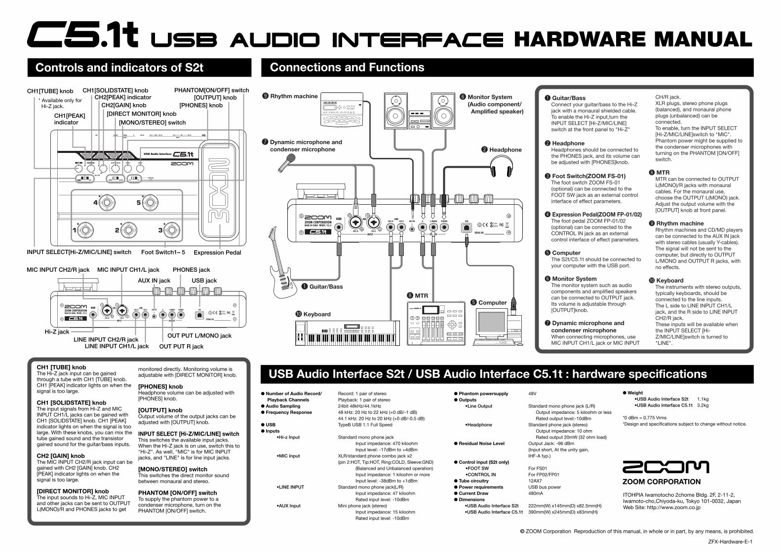
© ZOOM Corporation Reproduction of this manual, in whole or in part, by any means, is prohibited.
ZFX-Hardware-E-1
l Number of Audio Record/ Record: 1 pair of stereo Playback Channels Playback: 1 pair of stereol Audio Sampling 24bit 48kHz/44.1kHzl Frequency Response 48 kHz: 20 Hz to 22 kHz (+0 dB/-1 dB) 44.1 kHz: 20 Hz to 20 kHz (+0 dB/-0.5 dB)l USB TypeB USB 1.1 Full Speedl Inputs •Hi-z Input Standard mono phone jack Input impedance: 470 kiloohm Input level: -17dBm to +4dBm •MIC Input XLR/standard phone combo jack x2 (pin 2:HOT, Tip:HOT, Ring:COLD, Sleeve:GND) (Balanced and Unbalanced operation) Input impedance: 1 kiloohm or more Input level: -38dBm to +1dBm •LINE INPUT Standard mono phone jack(L/R) Input impedance: 47 kiloohm Rated input level: -10dBm •AUX Input Mini phone jack (stereo) Input impedance: 15 kiloohm Rated input level: -10dBm
l Phantom powersupply 48Vl Outputs •Line Output Standard mono phone jack (L/R) Output impedance: 5 kiloohm or less Rated output level:-10dBm •Headphone Standard phone jack (stereo) Output impedance: 10 ohm Rated output 20mW (32 ohm load)l Residual Noise Level Output Jack: -96 dBm (Input short, At the unity gain, IHF-A typ.)l Control input (S2t only) •FOOT SW For FS01 •CONTROL IN For FP02/FP01l Tube circuitry 12AX7l Power requirements USB bus powerl Current Draw 480mAl Dimensions •USB Audio Interface S2t 222mm(W) x145mm(D) x82.5mm(H) •USB Audio Interface C5.1t 390mm(W) x245mm(D) x83mm(H)
l Weight •USB Audio Interface S2t 1.1kg •USB Audio Interface C5.1t 3.2kg
*0 dBm = 0.775 Vrms*Design and specifications subject to change without notice.
Controls and indicators of S2t Connections and Functions
USB Audio Interface S2t / USB Audio Interface C5.1t : hardware specificationsCH1 [TUBE] knobThe Hi-Z jack input can be gained through a tube with CH1 [TUBE] knob. CH1 [PEAK] indicator lights on when the signal is too large.
CH1 [SOLIDSTATE] knobThe input signals from Hi-Z and MIC INPUT CH1/L jacks can be gained with CH1 [SOLIDSTATE] knob. CH1 [PEAK] indicator lights on when the signal is too large. With these knobs, you can mix the tube gained sound and the transistor gained sound for the guitar/bass inputs.
CH2 [GAIN] knobThe MIC INPUT CH2/R jack input can be gained with CH2 [GAIN] knob. CH2 [PEAK] indicator lights on when the signal is too large.
[DIRECT MONITOR] knobThe input sounds to Hi-Z, MIC INPUT and other jacks can be sent to OUTPUT L(MONO)/R and PHONES jacks to get
monitored directly. Monitoring volume is adjustable with [DIRECT MONITOR] knob.
[PHONES] knobHeadphone volume can be adjusted with [PHONES] knob.
[OUTPUT] knobOutput volume of the output jacks can be adjusted with [OUTPUT] knob.
INPUT SELECT [Hi-Z/MIC/LINE] switchThis switches the available input jacks. When the Hi-Z jack is on use, switch this to "Hi-Z". As well, "MIC" is for MIC INPUT jacks, and "LINE" is for line input jacks.
[MONO/STEREO] switchThis switches the direct monitor sound between monaural and stereo.
PHANTOM [ON/OFF] switchTo supply the phantom power to a condenser microphone, turn on the PHANTOM [ON/OFF] switch.
HARDWARE MANUAL
ITOHPIA Iwamotocho 2chome Bldg. 2F, 2-11-2, Iwamoto-cho,Chiyoda-ku, Tokyo 101-0032, JapanWeb Site: http://www.zoom.co.jp
ZOOM CORPORATION
1 Guitar/BassConnect your guitar/bass to the Hi-Z jack with a monaural shielded cable.To enable the Hi-Z input,turn the INPUT SELECT [Hi-Z/MIC/LINE] switch at the front panel to "Hi-Z"
2 HeadphoneHeadphones should be connected to the PHONES jack, and its volume can be adjusted with [PHONES]knob.
3 Foot Switch(ZOOM FS-01)The foot switch ZOOM FS-01 (optional) can be connected to the FOOT SW jack as an external control interface of effect parameters.
4 Expression Pedal(ZOOM FP-01/02)The foot pedal ZOOM FP-01/02 (optional) can be connected to the CONTROL IN jack as an external control interface of effect parameters.
5 ComputerThe S2t/C5.1t should be connected to your computer with the USB port.
6 Monitor SystemThe monitor system such as audio components and amplified speakers can be connected to OUTPUT jack. Its volume is adjustable through [OUTPUT]knob.
7 Dynamic microphone and condenser microphone
When connecting microphones, use MIC INPUT CH1/L jack or MIC INPUT
CH/R jack. XLR plugs, stereo phone plugs (balanced), and monaural phone plugs (unbalanced) can be connected.To enable, turn the INPUT SELECT [Hi-Z/MIC/LINE]switch to "MIC". Phantom power might be supplied to the condenser microphones with turning on the PHANTOM [ON/OFF] switch.
8 MTRMTR can be connected to OUTPUT L(MONO)/R jacks with monaural cables. For the monaural use, choose the OUTPUT L(MONO) jack. Adjust the output volume with the [OUTPUT] knob at front panel.
9 Rhythm machineRhythm machines and CD/MD players can be connected to the AUX IN jack with stereo cables (usually Y-cables). The signal will not be sent to the computer, but directly to OUTPUT L/MONO and OUTPUT R jacks, with no effects.
0 KeyboardThe instruments with stereo outputs, typically keyboards, should be connected to the line inputs. The L side to LINE INPUT CH1/L jack, and the R side to LINE INPUT CH2/R jack. These inputs will be available when the INPUT SELECT [Hi-Z/MIC/LINE]switch is turned to "LINE".
6 Monitor System (Audio component/ Amplified speaker)
9 Rhythm machine
2 Headphone
1 Guitar/Bass
7 Dynamic microphone and condenser microphone
5 Computer8 MTR
0 Keyboard
CH1[SOLIDSTATE] knob
CH2[GAIN] knob
Expression Pedal
CH1[TUBE] knob
CH1[PEAK] indicator
CH2[PEAK] indicator
[DIRECT MONITOR] knob[PHONES] knob
[OUTPUT] knob
[MONO/STEREO] switch
Foot Switch1– 5
PHANTOM[ON/OFF] switch
INPUT SELECT[Hi-Z/MIC/LINE] switch
MIC INPUT CH1/L jack
Hi-Z jack
MIC INPUT CH2/R jack
USB jackAUX IN jack
LINE INPUT CH2/R jack
PHONES jack
OUT PUT L/MONO jack
OUT PUT R jackLINE INPUT CH1/L jack
* Available only for Hi-Z jack.

Cubase LE 4 installation Connections and preparation Use Cubase LE 4 to record
Cubase LE 4 installation Windows Vista / XPConnections and preparation Use Cubase LE 4 to record
To connect this unit to a computer running Windows Vista (or Windows XP) and to enable audio input/output, proceed as follows. The installation description uses Windows Vista as an example.
Insert the supplied "Cubase LE 4" DVD-ROM into the DVD drive of the computer, and perform the installation steps.
When you insert the DVD-ROM, a screen asking what you want to doappears. Select "Open folder to view files". When the contents of the DVD-ROM are shown, open the "CubaseLE 4 for Windows" folder by double-clicking on it, and then double-click the executable "Setup" ("Setup.exe") file to start the installationprocess.
HINT
If nothing happens when you insert the DVD-ROM, open the Start menu and select "Computer" ("My Computer" in Windows XP). Then double-click the "Cubase LE 4" DVD-ROM icon to display the contents of the DVD-ROM.
NOTE
When the installation of Cubase LE 4 is complete, a screen asking about installation of activation (software license authentication) management software appears. Install this software, because it is required for registering Cubase LE 4.
Connect this unit to the computer using a USB cable.
NOTE
Use a high-quality USB cable and keep the connection as short as possible. If an electric power is supplied to this unit via a USB cable is more than 2 meters in length, the low voltage warning indication may appear.
HINT
No special steps are necessary for canceling the USB connection. Simply disconnect the USB cable from the computer.
When you connect this unit for the first time to a computer runningWindows Vista, a message saying "New Hardware Found" willappear.Before proceeding, wait a while until this message disappears.
Bring up the "Sound" window from the Control Panel and make the input device setting for the computer.
To bring up the "Sound" window, select "Control Panel" from theStart menu and click "Hardware and Sound", then click "Sound".
In the "Sound" window, verify that "ZOOM S2t C5.1t Audio" is listedunder the Play and Record devices and that the device is checked. (Toswitch between Play and Record, click the tabs at the top of thewindow.) If the device is not checked, right-click on the icon for the device andclick "Set as Default Device" so that a check mark appears.
Start Cubase LE 4. Then access the "Devices" menu, select "Device Setup..." and click "VST Audio System".
To start Cubase LE 4, double-click the Cubase LE 4 shortcut icon thatwas created on the desktop. After startup, select "ZOOM S2t C5.1tASIO" as the ASIO driver in the right section of the Device Setupwindow. When you change the ASIO driver selection, a confirmationmessage appears. Click the "Switch" button.
The device indication in the left section of the window now shows"ZOOM ASIO Driver" as the ASIO driver. Click on this indication to select it, and then click the "Control Panel"button in the right section of the Device Setup window.
The window that appears lets you set the latency for the ASIO driver.The latency should be set to a value that is as low as possible withoutcausing sound dropouts during recording and playback.
When the setting is complete, click the OK buttons in the respectivewindows to return to the startup condition of Cubase LE 4.
[INPUT] jack Computer
Guitar or other instrument
USB cableThis unit
[OUTPUT] jack
Audio system or other hi-fi playback equipment
ASIO driver
Click here...
Then click here
USB/Cubase LE 4 Startup Guide USB/Cubase LE 4 Startup Guide
This USB/Cubase LE 4 Startup Guide explains how to install Cubase LE 4 on a computer, make connections and settings for this unit, and perform recording.
From the "Devices" menu of Cubase LE 4, select "VST Connections" and select the device containing the string "ZOOM S2t C5.1t In (Out)" as input port and output port.
Use the tabs at top left to switch between input and output, and verifythat "ZOOM S2t C5.1t In (Out)" is selected as device port. If anotherdevice is selected, click the device port field and change the selection.
Access the "File" menu and select "New Project".
The new project window appears. Here you can select a projecttemplate.
Make sure that the "Empty" template is selected, and click the OK button.
A window for selecting the project file save location appears.
After specifying a suitable project file save location (such as the desktop), click the OK button.
A new project is created, and the project window for controlling mostof the Cubase LE 4 operations appears.
To create a new audio track, access the "Project" menu and select "Add track". In the submenu that appears, select "Audio".
he Add Track window for specifying the number of audio tracks andthe stereo/mono setting appears.
In this example, set the number of tracks to "1" and select stereo, thenclick the OK button.
A new stereo audio track is added to the project window.
Make the following settings for the newly created audio track.
HINT
The Inspector shows information about the currently selected track. If nothing is shown, click on the track to select it.
Connect the guitar or other instrument to the [INPUT] jack of this unit.
To use the ZOOM ZFX Plug-in for recording, select it for insertion as follows.
Project window
Select number of tracks Select stereo/mono setting
New audio track
If the Inspector is not shown, click here to toggle the Inspector show/hide setting.
Select the input/output path for the track. (The path name assigned to the this unit in step 6 is shown here.) To select a different path, click this section and select a new path from the menu that appears.
Inspector (area for making detailed track settings)
Click "Inserts" in the Inspector to enlarge the insert slot.
Click on the insert slot and select the ZOOM ZFX Plug-in.
Continued overleaf
Cubase LE 4 installation Windows Vista / XPConnections and preparation Use Cubase LE 4 to record

If the ZFX Plug-in is not shown
If the ZFX Plug-in does not appear in the list of insert effects, perform the following steps to specify the folder where it is located.
(1) From the "Devices" menu of Cubase LE 4, select "Plug-in Information" to open the window.
(2) In the "Plug-in Information" window, click the "VST 2x Plug-in Paths" button.
(3) Click the "Add" button.
(4) In the tree display that appears, select the folder where the ZOOM ZFX Plug-in is located (C:\Program Files\Zoom\ZFX) and click the [OK] button.
(5) Restart Cubase LE 4 to enable the change.
HINT
The plug-in effect is inserted in the track output (after recording), not in the track input (before recording). Therefore you can try out various effects without altering the recorded data.
Access the "Devices" menu of Cubase LE 4 and select "Mixer".
The mixer window appears. This window shows the channel assigned to the created track, and themaster channel.
Perform the following steps here.
While playing your instrument, adjust the output level of this unit to achieve a suitable recording level for Cubase LE 4.
The recording level for Cubase LE 4 can be checked with the levelmeter for the channel that is assigned to the recording standby track.Set the level as high as possible without causing the meter to reach theend of the scale. To adjust the level, do not use the fader of Cubase LE 4. Insteadchange the recording level and gain settings at this unit.
NOTE
The level meter as in the above illustration shows the signal level after processing in this unit. When you pluck a guitar string the meter may register with a slight delay, but this is not a defect.
Click on the monitoring button to turn it off and use the [DIRECT MONITOR] knob of this unit to adjust the monitoring volume.
This will allow adjustment with less latency than when going throughCubase LE 4.
NOTE
Contrary to the above recommendation, when a plug-in effect is inserted, the monitoring button should be lit in orange and the [DIRECT MONITOR] knob of this unit should be turned down. If the knob is turned up, the sound will have a flanger-like quality.
Channel assigned to audio track Master channel
Mixer window
Click monitoring button so that it lights up in orange.
Click recording standby button so that it lights up in red, to activate recording standby condition.
Level meter
Verify that the transport panel is being shown.
If the transport panel is not shown, access the "Transport" menu andselect "Transport Panel".
To start recording, click the Record button in the transport panel.
Recording starts. As you play your instrument, the waveform appears in real time in theproject window. To stop recording, click the Stop button in the transport panel.
Check the recorded content.
To play the recording, perform the following steps.
HINT
If no sound is heard when you click the Play button after recording, check the VST connection settings (step 6) once more.
NOTE
To continue using Cubase LE 4, a process called activation (license authentication and product registration) is necessary. When you start Cubase LE 4, a screen offering to register the product will appear. Select "Register Now". A web site for registration will open in your Internet browser. Follow the instructions on that page to register and activate the product.
For optimum enjoyment
While using Cubase LE 4, other applications may slow down drastically or a message such as "Cannot synchronize with USB audio interface" may appear. If this happens frequently, consider taking the following steps to optimize the operation conditions for Cubase LE 4.
(1) Shut down other applications besides Cubase LE 4.
In particular, check for resident software and other utilities.
(2) Reduce plug-ins (effects, instruments) used by Cubase LE 4.
When there is a high number of plug-ins, the computer's processing power may not be able to keep up. Reducing the number of tracks for simultaneous playback can also be helpful.
If applications still run very slowly or the computer itself does not function properly, disconnect this unit from the computer and shut down Cubase LE 4. Then reconnect the USB cable and start Cubase LE 4 again.
Stop button Record button
Go to beginning of project Play button
Move the fader of the master channel (as displayed in step 13) fully down.
1.
Use the button in the transport panel to move to the beginning of the project.
2.
Raise the fader of the master channel to obtain a suitable volume.
4.
Click the Play button in the transport panel to start playback.
3.
Continued from front
Cubase LE 4 installation Windows Vista / XPConnections and preparation Use Cubase LE 4 to record
ZFX-CubaseLE4-E-1
![Operation Manual - Zoom...[AC adapter operation] • Be sure to use only an AC adapter which supplies 9 V DC, 300 mA and is equipped with a "center minus" plug (Zoom AD-0006). The](https://static.fdocuments.in/doc/165x107/61452cd834130627ed50d12e/operation-manual-zoom-ac-adapter-operation-a-be-sure-to-use-only-an-ac.jpg)