Zoning Application. Copyright 2011 Trane 2 Zoning Application Agenda Application Overview --Benefits...
67
Zoning Application
-
Upload
karley-embry -
Category
Documents
-
view
213 -
download
0
Transcript of Zoning Application. Copyright 2011 Trane 2 Zoning Application Agenda Application Overview --Benefits...

Zoning ApplicationZoning Application

Copyright 2011 Trane2
Zoning ApplicationZoning Application
Agenda
Application Overview --Benefits & Challenges with Zoning
HVAC System DesignsConventional Vs Zoning
Excess Air --Defining --Management Strategies

Copyright 2011 Trane7
Zoning ApplicationZoning Application
Why Zoning and how can a customer benefit from zoning?
Have you come across a zoning system that did not provide these benefits?
Zoning is the intentional restriction of capacity (air flow) into a specific zone.

Copyright 2011 Trane8
Zoning ApplicationZoning Application
Air Conditioning Contractors of America (ACCA) provides standards in designing HVAC system.
There are standards for conventional systems and standards for zoning systems.
Manual J8 is required for the proper application & design of zoning systems.
Which manuals are mandatory?

The lower green line shows the average sensible heat gain. This is used to size the HVAC system
The red line represents the actual hourly heat gain.
The yellow line represents a 30% buffer zone. Room temperature swings may be extreme if hourly load conditions exceed this buffer limit.
Zone Heat Gain Sensible Heat Gain Graph of Manual J8
Software will show “Powered by Manual J”BTU’s
Time

Some applications will have extreme excursions. This is especially true for homes with large glass loads or condominiums (small interior loads with only one external wall).
If zoning is applied, the duct size must be sized upon the red line peak excursion.
Zone Heat Gain BTU’s
Time

Copyright 2011 Trane11
Zoning ApplicationZoning Application
The fundamentals remain the same:An accurate heat load calculation & proper duct design is critical.
Zoning should never be applied to oversized systems or undersized ducting.
The HVAC system is sized on _________________________
The duct system is sized on _________________________

Copyright 2011 Trane12
Zoning ApplicationThe BasicsZoning ApplicationThe Basics
Always start with a “common sense” approach when applying zoning. There are several tools out there to assist with calculations, but always stay focus on the obvious:
•Rooms that are open to each other should be in the same zone.
•With multiple story homes, each floor should be a zone.
•Unique rooms (detached rooms or rooms with large glass loads) should be individually zoned.
Copyright 2011 Trane13
Zoning ApplicationThe BasicsZoning ApplicationThe Basics
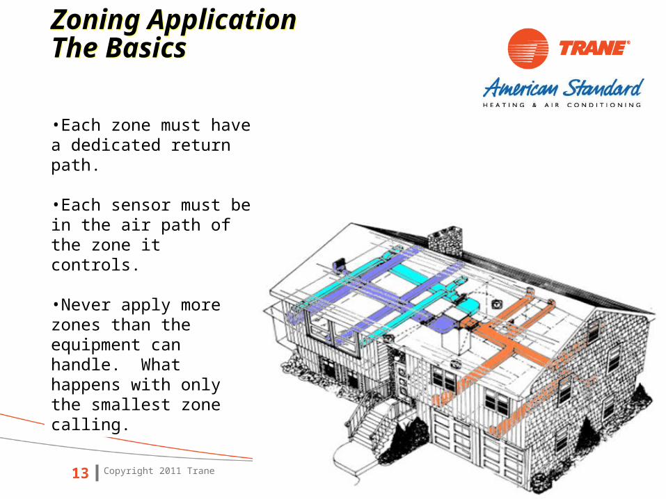
•Each zone must have a dedicated return path.
•Each sensor must be in the air path of the zone it controls.
•Never apply more zones than the equipment can handle. What happens with only the smallest zone calling.

Copyright 2011 Trane14
Zoning Application Daily Solar Load ShiftsZoning Application Daily Solar Load Shifts
Room grouping from ACCA Manual RSDaily solar shifts

Living Room
Kitchen
Guest Room 1
Master Bed
Add 1
Ad 2 Add 3
Office
Dining
Guest Room 2
EW
S
N

Copyright 2011 Trane16
Zoning ApplicationSeasonal Load ShiftsZoning ApplicationSeasonal Load Shifts
Room grouping from ACCA Manual RSSeasonal load shifts and the 15% rule.
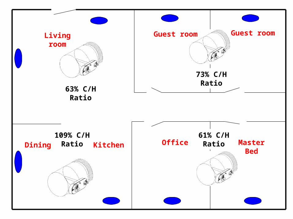
Living room
Kitchen
Guest room
Master Bed
Add 1
Ad 2 Add 3
OfficeDining
Guest room
61% C/HRatio
73% C/HRatio
63% C/HRatio
109% C/HRatio

Copyright 2011 Trane18
Zoning ApplicationExcess AirZoning ApplicationExcess Air
What happens to a system when air flow is restricted?
How can this reduction in air flow be managed?

Copyright 2011 Trane19
Zoning ApplicationExcess Air Management StrategiesZoning ApplicationExcess Air Management Strategies
Bypass
Dump
Variable Speed Air Flow Reduction
Multi Capacity Systems
Relief
Over Blow
Excess air must be managed based on worst case conditions!

Copyright 2011 Trane20
Zoning ApplicationDST Thermal LimitsZoning ApplicationDST Thermal Limits

Copyright 2011 Trane21
Which is the smallest zone in cooling?
How much excess air must be managed?
Which is the smallest zone in heating?
How much excess air must be managed?
Copyright 2011 Trane22
Zoning ApplicationUnderstanding BypassZoning ApplicationUnderstanding Bypass
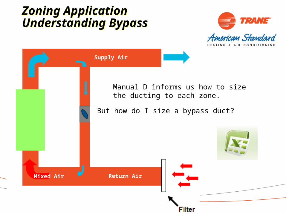
Manual D informs us how to size the ducting to each zone.
Return AirMixed Air
Supply Air
But how do I size a bypass duct?

Copyright 2011 Trane23
Zoning ApplicationCalculating BypassZoning ApplicationCalculating Bypass
Return AirMixed Air
Supply Air
Bypass Air Reading
Return Air Reading
Mixed Air Reading
Turn on the system with the smallest zone calling and the bypass damper wide open.
Obtain two dry bulb temperature readings:
Temp split from return & bypass air.
Temp split from return & mixed air.


Copyright 2011 Trane25
Zoning ApplicationUnderstanding BypassZoning ApplicationUnderstanding Bypass
Return AirMixed Air
Take a look at what happens with this much bypass.
Taken from the install guide of a popular zoning system.
This is 75% bypass

Temp splits with 36%
bypass on a 4-ton cooling
system.

Temp splits with 64%
bypass on a 4-ton cooling
system.

43% bypass on 80K 4-ton drive furnace
Temp Rise 30⁰ - 60⁰

18% bypass on 80K 4-ton drive furnace
Copyright 2011 Trane30
Zoning ApplicationZoning Application
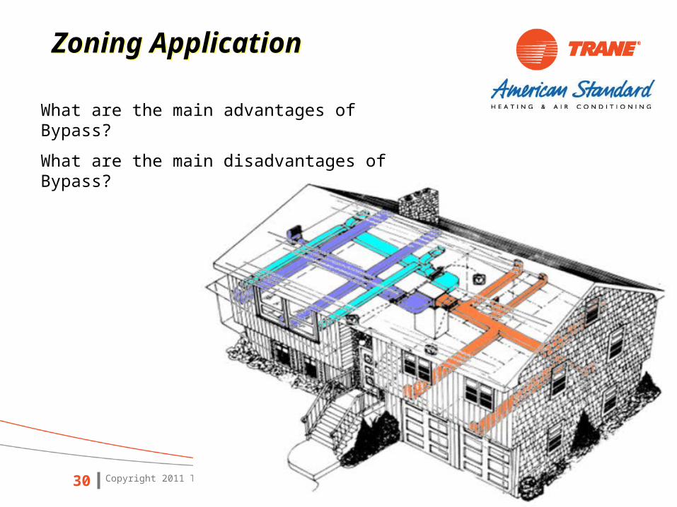
What are the main advantages of Bypass?
What are the main disadvantages of Bypass?

Copyright 2011 Trane31
Zoning Application$$$ Savings on Energy Bills?Zoning Application$$$ Savings on Energy Bills?
Will zoning deliver energy savings?
“The benefit of a set-up / set-back schedule depends on
the cycle time. Long periods (days or weeks) of set-up /
setback save energy. Short set-up / set-back periods (less than a day, maybe less than 16 hours) saves less energy, or may increase energy use.”
ACCA Preliminary Manual Zr

Copyright 2011 Trane32
Zoning Application$$$ Savings on Energy Bills?Zoning Application$$$ Savings on Energy Bills?
10.6 EER 9.7 EER 8.5 EER
4-ton AC system
Copyright 2011 Trane33
Zoning ApplicationVariable Speed Air Flow ReductionZoning ApplicationVariable Speed Air Flow Reduction
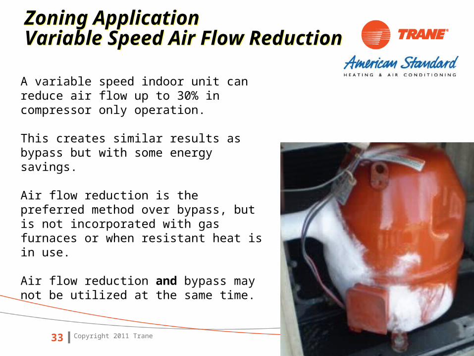
A variable speed indoor unit can reduce air flow up to 30% in compressor only operation.
This creates similar results as bypass but with some energy savings.
Air flow reduction is the preferred method over bypass, but is not incorporated with gas furnaces or when resistant heat is in use.
Air flow reduction and bypass may not be utilized at the same time.

Copyright 2011 Trane34
1985 CFM at 0.7 static consumes 824 watts.
A 30% air flow reduction will deliver1389 CFM.
1383 CFM = 396 Watts at 0.7 static.
Even if static remains constant as dampers close, blower reduction assists with energy savings.

Copyright 2011 Trane35
Zoning ApplicationMulti Capacity SystemsZoning ApplicationMulti Capacity Systems
Can multi capacity systems assist with zoning?

Copyright 2011 Trane36
Zoning ApplicationOver blowZoning ApplicationOver blow
Over blow makes the assumption that air will be redirected through the ducting as dampers close.

Copyright 2011 Trane37
Zoning ApplicationOver blowZoning ApplicationOver blow
This duct system is moving 600 FPM. How much air flow will this 8 inch duct deliver__________?
Static pressure & velocity rates will increase as dampers close. How much air will this 8 inch duct deliver at 900 FPM?
Can you count on over blow with a high static duct system?

Copyright 2011 Trane38
Zoning ApplicationSetting Duct Size -- WeightZoning ApplicationSetting Duct Size -- Weight
What are some advantages of an oversized duct system with zoning?
What are some disadvantages of an oversized duct system?
Should the zone control system know the duct size to each zone? Why?
Auto Zone Weighting or Manual Set up
Copyright 2011 Trane39

Copyright 2011 Trane40
A main duct is defined as any damper that controls more than one supply terminal.
Zoning ApplicationSetting Duct Size -- WeightZoning ApplicationSetting Duct Size -- Weight

Copyright 2011 Trane41
Zoning ApplicationTime to add it all upZoning ApplicationTime to add it all up
Time to calculate a basic two zone single stage system with psc motor. But first, how will I obtain the following information.
•The required air for each zone
•The amount of excess air that must be managed
•The maximum allowable bypass
•The amount of over blow (if any)
•The remaining amount of excess air

12”14”
700 CFM @ 900 feet per minute1000 CFM @ 900 feet per minute

12”
700 CFM @ 900 feet per minute
Cooling Mode
Blower set to deliver 1600 CFM.
The bedroom is the only zone calling and requires 36% of this air flow. The bedroom requires ________ CFM.
Due to the limitations of the furnace, the maximum bypass is 18% which is ________ CFM.
I need to find a home for the remaining ________ CFM.
Factor in over blow. The 12 inch duct can handle 700 CFM at 900 FPM (700 – ______required by bedroom = ______ CFM of over blow).
1600 CFM – 700 into the zone – ______bypass = _______CFM (_____%) of excess air.
How can we manage this excess air?

1600 CFM – 1000 into the zone ______bypass = _______CFM (_____%) of excess air.
How can we manage this excess air?
Blower set to deliver 1600 CFM.
The living room zone is the only zone calling and requires 64% of this air flow. The living room requires ________ CFM.
Due to the limitations of the furnace, the maximum bypass is 18% which is ________ CFM.
I need to find a home for the remaining ________ CFM.
Factor in over blow. The 14 inch duct can handle 1000 CFM at 900 FPM (1000 – ______required by living room = ______ CFM of over blow).
14”
1000 CFM @ 900 feet per minute
Cooling Mode

Blower set to deliver 1275 CFM.
The bedroom is the only zone calling and requires 43% of this air flow. The bedroom requires ________ CFM.
Due to the limitations of the furnace, the maximum bypass is 18% which is ________ CFM.
I need to find a home for the remaining ________ CFM.
Factor in over blow. The 12 inch duct can handle 700 CFM at 900 FPM (700 – ______required by bedroom = ______ CFM of over blow).
1275 CFM – 700 into the zone – ______bypass = _______CFM (_____%) of excess air.
How can we manage this excess air?
12”
700 CFM @ 900 feet per minute
Heating Mode

Blower set to deliver 1275 CFM.
The living room zone is the only zone calling and requires 57% of this air flow. The living room requires ________ CFM.
Due to the limitations of the furnace, the maximum bypass is 18% which is ________ CFM.
I need to find a home for the remaining ________ CFM.
Factor in over blow. The 14 inch duct can handle 1000 CFM at 900 FPM (1000 – ______required by living room = ______ CFM of over blow).
1275 CFM – 1000 into the zone – ______bypass = _______CFM (_____%) of excess air.
How can we manage this excess air?
14”
1000 CFM @ 900 feet per minute
Heating Mode

12”
700 CFM @ 900 feet per minute
Cooling mode bedroom calling.
576 CFM is required based on conventional system design .412 CFM is managed through over blow & bypass.
Cooling mode living room calling.
Bedroom damper stop must be set to manage 312 CFM. 20% relief.
14”
1000 CFM @ 900 feet per minute
Cooling mode living room calling.
1024 CFM is required based on conventional system design.288 CFM is managed by bypass.
Cooling mode bedroom calling.
Living room damper stop must be set to manage 612 CFM. 38% relief.

12”14”
700 CFM @ 900 feet per minute1000 CFM @ 900 feet per minute
Heating mode bedroom calling.
548 CFM is required based on conventional system design .382 CFM is managed through over blow & bypass.
Heating mode living room calling.
727 CFM is required based on conventional system design.503 CFM is managed by over blow & bypass.
Heating mode bedroom calling.
Living room damper stop must be set to manage 345 CFM. 27% relief.
Heating mode living room calling.
Bedroom damper stop must be set to manage 45 CFM. 4% relief.

14” 12”
1000 CFM @ 900 feet per minute 700CFM @ 900 feet per minute
Damper relief must be set for worst case conditions which is 20% for the cooling mode (only 4% required in heating mode).
The zone will receive 16% more air than is required during the heating mode.
Damper relief must be set for worst case conditions which is 38% for the cooling mode (only 27% required in heating mode).
The zone will receive 11% more air than is required during the heating mode.
Would a variable speed motor help? Why?
Would multi capacity systems help? Why
Living Room Damper Bedroom Damper

16” 14”
1500 CFM @ 900 feet per minute 1000 CFM @ 900 feet per minute
Would oversizing the duct system help?
Moving from a 12 to a 14 inch duct allows for an additional 300 CFM of over blow.
This reduces the living room cooling damper stop from 38% to 20%.
It reduces the living room heating damper stop from 27% to 4%.
Moving from a 14 to a 16 inch duct allows for an additional 500 CFM of over blow.
This reduces the bedroom cooling damper stop from 20% to 0%.
It reduces the bedroom heating damper stop from 4% to 0%.
What are the risks of oversizing ducting?

12” 8”
700 CFM @ 900 feet per minute 250 CFM @ 900 feet per minute
250 CFM @ 900 feet per minute 410 CFM @ 900 feet per minute
8” 10”
What happens as the number of zones increases?
How well will a single stage system work on 4 zone application?

12” 8”
700 CFM @ 900 feet per minute 250 CFM @ 900 feet per minute
250 CFM @ 900 feet per minute 410 CFM @ 900 feet per minute
8” 10”
What happens in a home with different zones at different temperatures?
Cooling
Heating
68⁰ 77⁰
84⁰75⁰
Cooling
Cooling

Copyright 2011 Trane57
Zoning ApplicationZoning Application
What are the chances any dealer / designer is going to go through all these steps?
How many zoning systems are working properly?

Copyright 2011 Trane58
Zoning ApplicationZoning Application
Bypass is a way to manage excess air.
The downfall is it’s extremely difficult to configure and impossible to maintain consistency.
The Comfortlink II / AccuLink zone system has the ability to manage excess air based on static pressure and discharge air temperature.
•System configuration is simplified.•System performance is improved.•Homeowner comfort is maximized.

Copyright 2011 Trane59
Zoning ApplicationZoning Application
The Comfortlink II / AccuLink zone system has two strategies for managing excess air:
Stand Alone Relief or Temperature / Pressure Bypass.
You can set these independently for heating & cooling modes.
Cooling Mode
Relief
Temperature / Pressure Bypass
Heating Mode
Relief
Temperature / Pressure Bypass

Copyright 2011 Trane60
Zoning ApplicationReliefZoning ApplicationRelief
Based on the installation set up (manual or auto zone weighting), the zone control knows:
•The size (weight) of each zone•The position of each damper•The blower speed (total air delivery)
The zone control knows how much air is being delivered into each zone and how much excess air must be managed.

Copyright 2011 Trane61
Zoning ApplicationReliefZoning ApplicationRelief
Once the zone control calculates the amount of excess air, it will distribute this air based on the following hierarchy:
•Open dampers in all calling zones--up to 100% if necessary.
•Open dampers (25% minimum) in the same mode zones that are not actively calling—up to 100% if necessary (an off zone is the same mode zone).
•Open dampers (25% minimum) in opposing mode zones.
Copyright 2011 Trane62
Zoning ApplicationTemperature / Pressure ControlZoning ApplicationTemperature / Pressure Control

Copyright 2011 Trane63
Zoning ApplicationTemperature / Pressure ControlZoning ApplicationTemperature / Pressure Control
The installation technician must pick a design static pressure when setting up the zone panel (from 0.4 to 1.0 inch of water column.
The zone panel evaluates the system static pressure and discharge air temperature.
Static pressure will increase as supply dampers close, and the zone panel will begin to open the bypass damper when the static reaches its configured target.

Copyright 2011 Trane64
Zoning ApplicationTemperature / Pressure ControlZoning ApplicationTemperature / Pressure Control
The ∆T from the return to the supply duct will increase as the bypass damper opens.
The zone control will freeze the bypass damper and initiate the relief strategy when the supply temperature is within 4 degrees from the trip limit setting.

Zoning ApplicationUnderstanding BypassZoning ApplicationUnderstanding Bypass
Return Air
Mixed Air
Supply Air
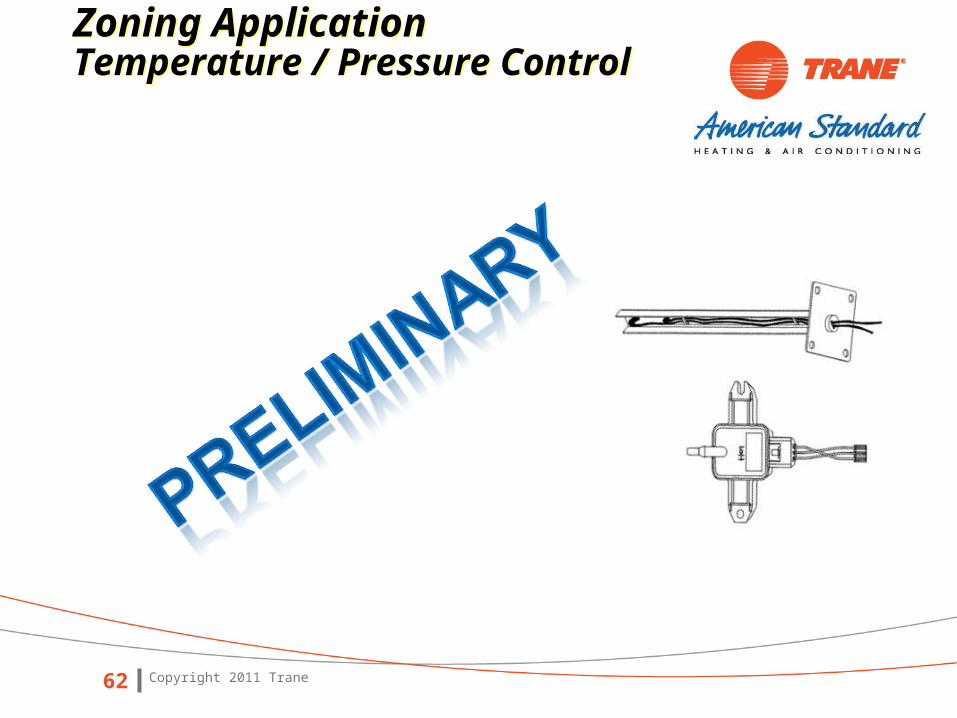
Static Pressure Transducer
Discharge Temperature Sensor
Four zone single stage cooling system with PSC air handler.
All zones are set in cooling mode.
Discharge temp sensor cut out is set at 42 degrees.
Bypass enabling static pressure set point is 0.7 inches of water.
Cooling Zone 1 Zone 2 Zone 3 Zone 4
Zone LV 0 0 0 0
Damper Position 0% 0% 0% 0%

Zoning ApplicationUnderstanding BypassZoning ApplicationUnderstanding Bypass
Return Air
Mixed Air
Supply Air
Cooling Zone 1 Zone 2 Zone 3 Zone 4
Zone LV 100 100 100 100
Damper Position 100% 100% 100% 100%
The thermostat came out of program mode. All zones have a load value of 100.
External static pressure is 0.5 and discharge air temperature is 60 degrees.
What is the bypass damper doing ____________?
What method of relief is being used _______________?

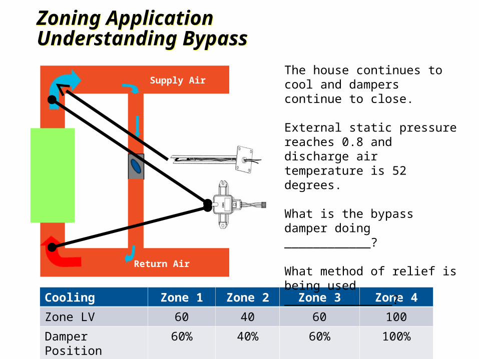
Zoning ApplicationUnderstanding BypassZoning ApplicationUnderstanding Bypass
Return Air
Mixed Air
Supply Air
Cooling Zone 1 Zone 2 Zone 3 Zone 4
Zone LV 75 60 80 100
Damper Position 75% 60% 80% 100%
The house is cooling off and the dampers start to close.
External static pressure increases to 0.7 and discharge air temperature is 56 degrees.
What is the bypass damper doing ____________?
What method of relief is being used _______________?
Zoning ApplicationUnderstanding BypassZoning ApplicationUnderstanding Bypass
Return Air
Mixed Air
Supply Air
Cooling Zone 1 Zone 2 Zone 3 Zone 4
Zone LV 60 40 60 100
Damper Position 60% 40% 60% 100%
The house continues to cool and dampers continue to close.
External static pressure reaches 0.8 and discharge air temperature is 52 degrees.
What is the bypass damper doing ____________?
What method of relief is being used _______________?

Zoning ApplicationUnderstanding BypassZoning ApplicationUnderstanding Bypass
Return Air
Mixed Air
Supply Air
Cooling Zone 1 Zone 2 Zone 3 Zone 4
Zone LV 0 0 50 100
Damper Position 0% 0% 50% 100%
The house continues to cool and two dampers close.
External static pressure stabilized at 0.85 and discharge air temperature dropped to 45 degrees.
What is happening with the bypass damper ____________?
What method of relief is being used _______________?

Zoning ApplicationUnderstanding BypassZoning ApplicationUnderstanding Bypass
Return Air
Mixed Air
Supply Air
Cooling Zone 1 Zone 2 Zone 3 Zone 4
Zone LV 0 0 50 100
Damper Position 0% 0% 100% 100%
The relief strategy is implemented.
External static pressure stabilized at 0.7 stabilizes at 48 degrees.
What is happening with the bypass damper__________?
How will the dampers react to relief__________________?

Zoning ApplicationUnderstanding BypassZoning ApplicationUnderstanding Bypass
Return Air
Mixed Air
Supply Air
Cooling Zone 1 Zone 2 Zone 3 Zone 4
Zone LV 0 25 50 100
Damper Position 0% 25% 50% 100%
The relief strategy is exited.
External static pressure stabilized at 0.6 stabilizes at 52 degrees.
What is happening with the bypass damper__________?
How will the dampers react to relief__________________?

Copyright 2011 Trane72
Zoning ApplicationZoning Application
Time for a vote:
Who wants to manually set up a zoning system?
How will auto zone weighting make this easier?
What are the benefits of intelligent relief?
What are the benefits of T/P bypass?

Copyright 2011 Trane73
Zoning ApplicationZoning Application
Summary:What steps must be taken when designing a zone system?
3) ACCA Manual RS. Follow the guidelines when joining multiple rooms into zones. Never lose focus on the common sense approach.
2) ACCA Manual J8, S & D. Size the system based on average block load design. Size the ducting on peak demands. Do not oversize equipment.
1) Consult with the homeowner and obtain their comfort desires.

Copyright 2011 Trane74
Zoning ApplicationZoning Application
4) What is the smallest zone and can the system manage the excess air.
6) Since the ducting is sized based on peak load conditions. Are the registers placed in a manner to mix air through the room at different velocity rates (ACCA Manual T)?
5) Have the steps been taken to manage excess air (i.e. have you installed a Comfortlink II / AccuLink zoning system)?
7) Follow through with the homeowner about system limitations and relief strategies.

Copyright 2011 Trane75
Questions?Questions?