Zinc-Rich Paint As Anode for Cathodic Protection of Steel … · P R O O F ON L Y 1 2 Zinc-Rich...
10
Zinc-Rich Paint As Anode for Cathodic Protection of Steel in Concrete Das, S.C. , Pouya, H.S. and Ganjian, E. Post-print deposited in Curve November 2015 Original citation: Das, S.C. , Pouya, H.S. and Ganjian, E. (2015) Zinc-Rich Paint As Anode for Cathodic Protection of Steel in Concrete . Journal of Materials in Civil Engineering, volume 27 (11): Article number 04015013. DOI: 10.1061/(ASCE)MT.1943-5533.0001243 http://dx.doi.org/10.1061/(ASCE)MT.1943-5533.0001243 American Society of Civil Engineers Copyright © and Moral Rights are retained by the author(s) and/ or other copyright owners. A copy can be downloaded for personal non-commercial research or study, without prior permission or charge. This item cannot be reproduced or quoted extensively from without first obtaining permission in writing from the copyright holder(s). The content must not be changed in any way or sold commercially in any format or medium without the formal permission of the copyright holders. CURVE is the Institutional Repository for Coventry University http://curve.coventry.ac.uk/open
Transcript of Zinc-Rich Paint As Anode for Cathodic Protection of Steel … · P R O O F ON L Y 1 2 Zinc-Rich...
Zinc-Rich Paint As Anode for Cathodic Protection of Steel in Concrete Das, S.C. , Pouya, H.S. and Ganjian, E. Post-print deposited in Curve November 2015 Original citation: Das, S.C. , Pouya, H.S. and Ganjian, E. (2015) Zinc-Rich Paint As Anode for Cathodic Protection of Steel in Concrete . Journal of Materials in Civil Engineering, volume 27 (11): Article number 04015013. DOI: 10.1061/(ASCE)MT.1943-5533.0001243 http://dx.doi.org/10.1061/(ASCE)MT.1943-5533.0001243 American Society of Civil Engineers Copyright © and Moral Rights are retained by the author(s) and/ or other copyright owners. A copy can be downloaded for personal non-commercial research or study, without prior permission or charge. This item cannot be reproduced or quoted extensively from without first obtaining permission in writing from the copyright holder(s). The content must not be changed in any way or sold commercially in any format or medium without the formal permission of the copyright holders.
CURVE is the Institutional Repository for Coventry University
http://curve.coventry.ac.uk/open
PROOF
ONLY
1
2 Zinc-Rich Paint as Anode for Cathodic Protection3 of Steel in Concrete4 Sunil C. Das1; Homayoon Sadeghi Pouya2; and Eshmaiel Ganjian3
5 Abstract: This paper describes the findings of the experimental works undertaken to investigate the performance of zinc-rich paint (ZRP) to6 provide cathodic protection to chloride-contaminated RC structures. The program of experimental works was designed and conducted to7 assess four principal properties, viz (1) conductivity, (2) adhesion with concrete (short term and long term), (3) durability, and (4) electro-8 chemical polarization. These properties considered together define the ability and effectiveness of the materials to act as an anode for9 impressed current cathodic protection. The research findings indicated that a specific proprietary ZRP product showed that optimum con-
10 ductance was obtained with three coats producing a 280–320 μm thickness, with good adhesion to the concrete substrate, in which values11 obtained ranged between 1.65 and 3.5 MPa with and without applied current. It was capable of withstanding/supporting high levels of current,12 i.e., more than 300 mA=m2, and the service life of the ZRP coating was estimated to be well in excess of 20 years at an applied current density13 of 10 mA=m2. DOI: 10.1061/(ASCE)MT.1943-5533.0001243. © 2015 American Society of Civil Engineers.
14 Author keywords: Zinc-rich paint anode; Cathodic protection; Corrosion; Chloride; Reinforcement.
15 Introduction
16 In recent years, there has been considerable interest and a substan-17 tial increase in the use of zinc and zinc alloy anodes and also some18 limited use of aluminum/aluminum alloy anodes for the cathodic19 protection (CP) of steel RC structures (Covino et al. 2002; Bullard20 et al. 2009). Zinc anodes in various forms have been developed over21 the years [SHRP-S-337 1993 (Strategic Highways Research Pro-22 gram 1993); National Cooperative Highway Research Program23 (NCHRP) Report 398 2009 (NCHRP 2009)], and a number of them24 are now commercially available. However, the performances of25 zinc anodes to provide sacrificial cathodic protection to steel26 reinforcement in chloride-contaminated concrete are found to be27 less than adequate to provide full protection to atmospherically ex-28 posed RC structures in the long term (Covino et al. 2002). Sagüés29 and Powers (1996) reported that the absence of direct wetting of the30 anode surface could result in long-term loss of adequate current31 delivery, even when the concrete was in contact with air of 85%32 relative humidity (RH) when sprayed zinc on the surface of con-33 crete was used as sacrificial anodes. Therefore, the application of34 zinc has traditionally been limited mainly to mitigate the incipient35 anode effect, but researchers and corrosion scientists in the United36 States, particularly the Department of Transportation (DOT) of37 Oregon, have actively encouraged applying thermally sprayed (TS)38 zinc and also Zn-Al or Al alloy coatings on a concrete surface,
39which is called metalizing the concrete (Apostolos 1984). Since40a trial installation in 1984 (Apostolos 1984), more than 80,000 m2
41TS zinc CP systems, both sacrificial or impressed current CP, have42been installed in Oregon alone over the period between 1995 and432005 (Covino et al. 2002; Bullard et al. 2009).44There is ample literature on the theoretical basis of the subject45and the applications of TS zinc anodes in various forms (Kepler46et al. 2000). For the CP of RC structures, some pioneered publi-47cations can be found (Covino et al. 2002; Bullard et al. 2009;48NCHRP Report 398 2009).
49Zinc-Rich Paints: Application and Chemical50Composition
51Zinc-rich paints (ZRPs) are widely used as an anticorrosion paint52on ferrous substrates, an alternative to hot-dip galvanizing (HDG),53an under coat or top coat, and also as a touch-up coat on galvanized54steel to provide corrosion protection of steel in moderately severe55environments and cathodic protection to steel substrates in corro-56sive marine atmospheric environments (Morcillo et al. 1990;57Abreau et al. 1996; Hare 1998). It is often quoted as cold galva-58nizing. It has also been effectively used to protect steel structures59fully and/or partially immersed in sea water, e.g., the ship’s hull,60offshore platforms, and jetties (Zhang 1996).61The metallic zinc content in the dry film is a very important62parameter to be emphasized in the technical specifications of zinc-63rich paints. However, as observed by Lindquist et al. (1985), this64parameter is not the only factor determining the performance of this65kind of paint. For example, Fragata et al. (1987), Amo and Giùdice66(1990), and Pereira et al. (1990) verified that the chemical nature of67the binder and zinc particle size are also very important.68The zinc dust, which has a spherical or lamellar shape or a com-69bination of both, is dispersed in an inorganic, usually orthosilicates,70or organic binder, usually epoxies (Wicks et al. 1994). These par-71ticles must be in electrical contact between themselves and the72metallic substrate to ensure a well-established electrical conduction73within the coating. In such conditions of percolation, a galvanic74coupling is created between zinc and the substrate (steel), which75is nobler than the zinc. Then, zinc can preferentially dissolve, acting
1Principal Engineer, Amey, International Design Hub, 20 ColmoreCircus, Birmingham B4 6AT, U.K.
2Research Fellow, Faculty of Engineering and Computing, Dept. ofCivil Engineering, Architecture and Building, Coventry Univ., Sir JohnLaing Building, Coventry CV1 5FB, U.K.
3Reader in Civil Engineering Materials, Faculty of Engineering andComputing, Dept. of Civil Engineering, Architecture and Building,Coventry Univ., Sir John Laing Building, Coventry, CV1 5FB U.K.(corresponding author). E-mail: [email protected]
Note. This manuscript was submitted on March 31, 2014; approved onNovember 12, 2014No Epub Date. Discussion period open until 0, 0;separate discussions must be submitted for individual papers. This paper ispart of the Journal of Materials in Civil Engineering, © ASCE, ISSN0899-1561/(9)/$25.00.
© ASCE 1 J. Mater. Civ. Eng.
PROOF
ONLY
76 as a sacrificial pigment and allowing a cathodic protection of77 the substrate. Many studies (Fleiu et al. 1989; Pereira et al. 1990,78 Armas et al. 1992) exist in the literature and relate the protection79 mechanisms and degradation processes of such coatings. Physico-80 chemical properties and corrosion resistance of solvent-based ZRPs81 strongly depend on pigment, i.e., zinc, volume concentration82 (PVC), shape, and size of the zinc dust (Vilche at al. 2002; Abreu83 et al. 1997). In common liquid ZRP, zinc is usually introduced as84 spherical pigments, with a mean diameter ranging from 5 to 10 μm.85 To ensure good electrical contacts between zinc pigments and86 the steel substrate, a high pigment concentration is required, which87 is usually above 60% by volume in solvent-based ZRPs (Vilche88 et al. 2002).89 A literature search indicated no prior works on ZRP as an anode,90 particularly as an impressed current CP anode for the CP of RC,91 except for some trials as a sacrificial anode (Apostolos 1984), but92 the main aim of these trials was to compare and contrast the per-93 formance of ZRP applied directly on exposed steel reinforcement94 to that of the galvanized steel reinforcement and/or other anticor-95 rosion paints for the exposed and corroding reinforcement. A case96 study (Das 2012) described the application of a ZRP on partially97 immersed concrete piles at Bangor Harbour to provide sacrificial98 cathodic protection (Das 2012). The specific objectives of this re-99 search were to evaluate the performance of zinc-rich paints as an
100 impressed current anode system for cathodic protection (ICCP) of101 RC structures.
102 Experimental Program
103 A review of commercially available zinc-rich paints has identified104 one proprietary product consisting of 96% zinc as the most prom-105 ising candidate material for this research. This off-the-shelf com-106 mercially available ZRP product is a single-pack zinc coating that107 is easy to apply by brush, roller, spraying, or dipping under any108 atmospheric condition. Because of commercial confidentiality, it109 is not possible to disclose the name of the manufacturer or the full110 chemical composition of the ZRP. The main components are zinc111 powder, aromatic hydrocarbons, and a binder. A dry layer of paint112 consists of 96% zinc, which is pure to 99.995% and homo-113 geneously dispersed throughout the layer. The ZRP coating dries114 by evaporation of the solvent. Further, the unique characteristic of115 this ZRP is that each new layer reliquidizes the former zinc layer so116 that both layers form one homogeneous layer (Das 2012).117 Four sets of experiments were designed and conducted in this118 part, including (1) a conductivity test, (2) adhesion test, (3) durabil-119 ity test, and (4) polarization test. For each set of tests, special con-120 crete test specimens were made with slight variations in the121 concrete mix design but basically keeping similar characteristic122 concrete properties. The concrete mix designs were to create two123 different types of concrete, with a low and high water-to-cement124 (w/c) ratio of 0.53 and 0.83, respectively. Some concrete specimens125 with different levels of chloride deliberately added in the concrete126 mix to stimulate active corrosion of steel reinforcement were also127 produced.
128 Specimen Preparations and Test Setup
129 The specimens’ preparation and procedures for each test program130 are briefly described subsequently.
131 Conductivity Test
132 Conductance of the ZRP material was determined by measuring133 the cross-film resistance. This was undertaken to determine an
134optimum number of coats applied on a nonconducting substrate135to achieve an optimum conductivity.136A total of three 180 × 250-mm compressed hardboard (wood137pulp) specimens with electrical connections comprising of two thin138copper strips (1.5 × 10 mm × 180 mm) with electrical wires sol-139dered were fixed onto the hardboard using an epoxy adhesive be-140fore ZRP coating. All hardboard specimens were given a total of141five coats, with the exception of Hardboard Number 3 (HB 3),142which was given a total of 10 coats. Each measured coat was aimed143at achieving a wet film mass of 12.4 g, which corresponds to a144theoretical dry film thickness of 60 μm. For all hardboard speci-145mens, when each applied coat has become sufficiently dry (approx-146imately 24 h), the resulting thickness of paint was measured147by using a digital venire calliper (0–150 mm range; accuracy of1480.01 mm). Measurements were carried out at approximately 20149places to calculate an average thickness.150The direct current (DC) resistance of the coating (dry) of each151application was measured across the two copper strips using a stan-152dard digital volt meter (DVM). A number of measurements were153made for each coat over a period of at least 24 h or until a constant154reading was obtained. This was repeated following each coat155application.
156Adhesion Strength
157The adhesion strength was determined using the adhesion tester158Elcometer 106/6, all in accordance with the procedure recom-159mended by CIRIA (1993) and Elcometer (2004). A total of two160grades of concrete specimens, representing low w/c ratio and high161w/c ratio concrete, with target compressive strengths of 40 and16220 MPa, respectively, were cast in accordance with BS EN 206-1163(British Standards Institution 2000).164Table 1 gives the concrete mix design. For each concrete mix,165three (three No.) cube samples (150 × 150 × 150 mm) with no166chloride added to the test specimen were produced. A total of 2 days167after demolding, specimens were fully immersed in a curing tank168for 28 days and then allowed to dry in air before zinc coating.169To assess the effect of the concrete surface profile on the adhe-170sion strength of the ZRP coating, each grade of concrete specimens171was prepared to produce three different levels of surface roughness.172These are defined as (1) very high roughness (VHR), where most of173the aggregates were exposed; (2) high roughness (HR), where some174aggregates were exposed; and (3) medium roughness (MR), where175mainly the cement laitance layer was removed with little or no176aggregates exposed. Table 2 summarizes the tools used to create177surface profiles and the roughness classifications that are qualita-178tive on the basis of visual assessment.179The prepared concrete substrates were then coated with the ZRP.180A total of four coats were applied by brush to achieve a dry film181thickness (DFT) of approximately 200–350 μm. The coating of182ZRP by brush was found to be as simple as painting with domestic183emulsion paint. Each coat of paint was applied after allowing the184previous coat to dry for 24 h. After each application of paint, the185wet and dry mass of paint was measured, and finally the total mass186of dry paint of a number of coats was measured to determine the187total DFT. The adhesion strength of the ZRP was determined first188within 24 h after the final coat was allowed to dry and also after189allowing the dry paint film to age for a total 56 days, i.e., at the end190of the environmental durability testing described under Item 3.191The adhesion strength was determined using an adhesion tester192Elcometer 106/6, all in accordance with the procedure recom-193mended by CIRIA (1993) and Elcometer (2004). Briefly, the test194was conducted using 20-mm-diameter high-strength aluminum al-195loy dollies bonded onto the test surface by means of an epoxy resin
© ASCE 2 J. Mater. Civ. Eng.
PROOF
ONLY
196 adhesive. After curing of the resin, the adhesion tester was placed197 in position and the indicator dial was set to zero. Then, the hand198 wheel was tightened until the pulling force to the dolly caused the199 break away from the surface and the pull-off force was read off the200 instrument dial, and the results were converted to bond strength201 in MPa.
202 Environmental Durability
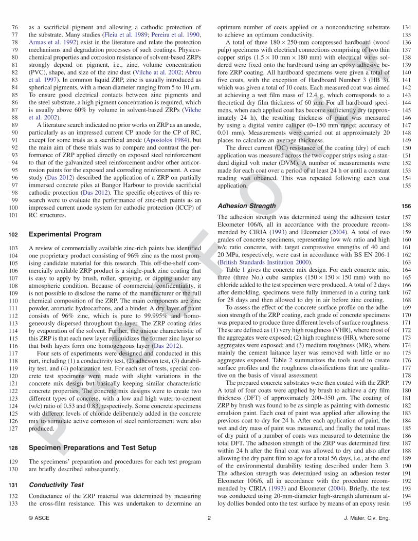
203 The objectives of the environmental durability test were to inves-204 tigate the effect of humidity and temperature on zinc paint with and205 without CP and to assess, at the end of 40 cycles, the bond strength206 between paint and concrete. A total of three cubes were used207 for this experiment. A total of three 150-mm concrete cubes were208 prepared with the concrete mix design, as given in Table 1, and209 cast with 0, 1, and 3% chloride by the mass of cement (as NaCl)210 added to the concrete mixes. The cube samples were cast with two211 10-mm-diameter steel reinforcement bars, one macrocell corrosion-212 measuring probe named beta-probe without NaCl, and one Ag/213 AgCl reference electrode, as shown in Fig. 1. Cable connections214 to elements were insulated with heat-shrink sleeves. Specimens215 were cured for 7 days in the curing tank at 20°C and 98% RH each.216 The cubes were then applied with three coats of zinc paint on the217 top face, allowing 24 h between coats for each coat to dry. The zinc218 coating thickness for each cube was determined. The thickness of219 the ZRP applied on the concrete surface of all the cubes was220 calculated and found in the range of 232–234 μm.221 The cubes were then placed in plastic trays. The painted top222 surface was faced up and partially filled with test solutions without223 covering the top zinc coated surface: one tray with distilled water,224 one tray with a 1% chloride solution, and one tray with a 3.5%225 chloride solution. All three cubes were then placed in the environ-226 mental chamber exposed to 40 temperature and humidity cycles,227 and each cycle was set for 24 h. The chamber started at 20°C and228 50% humidity. Then, it ramps to 50°C and 90% humidity in 1 h and229 remains in these conditions for another 8 h. Then, it ramps down to230 20°C and 50% humidity in 1 h and remains in these environmental231 conditions for another 14 h.
232The procedures used for the environmental durability test are233briefly described subsequently. Before environmental testing com-234menced, the three specimens were placed in their respective trays,235and the potentials of the rebars were monitored, with respect to Ag/236AgCl reference electrodes, once a day for 14 days. The corrosion237current of the rebars was also measured by connecting a precision238resistor across the rebars and the beta-probes (macrocorrosion cell).239The environmental chamber was set at 50°C, 90% RH, and then the240minicathodic protection system was set up by connecting the cables241from the rebars to the negative terminal and the cable connected to242the copper strip (as a primary anode) embedded in the ZRP anode243system to the positive terminal of a constant current/constant volt-244age DC power supply unit. Fig. 2 gives the electrical circuit dia-245gram for the test. Then, the power supplies to the environmental246chamber and CP system were switched on to begin testing, and247at the end of each cycle, a number of parameters were measured
Table 1. Concrete Mix Proportions for Environmental Cube Specimens
T1:1 Component
Concrete mix design
T1:2Low w/c G High w/c P
T1:3 Water-cement ratio 0.50 0.80T1:4 Ordinary Portland cement (kg=m3) 300 200T1:5 Water (kg=m3) 150 160T1:6 Uncrushed coarse aggregate (kg=m3) (4.75–10 mm size) 1,300 1,175T1:7 Fine aggregate (kg=m3) (sand) ≈65% passing 600-μm sieve 670 867T1:8 Slump test (mm) ≈10 ≈20
T1:9 Amount of compaction (vibrating table) (m=s2)T1:10 Shock table mode of vibration (≈8 g) Cubes: G1–G5 Cubes: P1–P5T1:11 Curing process (2 days after demolding specimens) Fully immersed in curing tank for 28 days and then allowed to
dry in air before zinc coating
Table 2. Summary Illustrating the Methodology and Engineering Judgment Used to Obtain Different Levels of Concrete Substrate Roughness through TrialExperimentation
T2:1 Substrate roughnessdegree (terminology) Tool utilized Manual/automatic Degree of aggregates exposed
T2:2 VHR Needle gun (compressed air) Automatic Most aggregates exposedT2:3 HR Needle gun (compressed air) Automatic Some aggregates exposedT2:4 MR Wire brush Manual Little/no aggregates exposed
F1:1Fig. 1. Arrangement of rebars, reference electrode, and probe forF1:2environmental durability test
© ASCE 3 J. Mater. Civ. Eng.
PROOF
ONLY
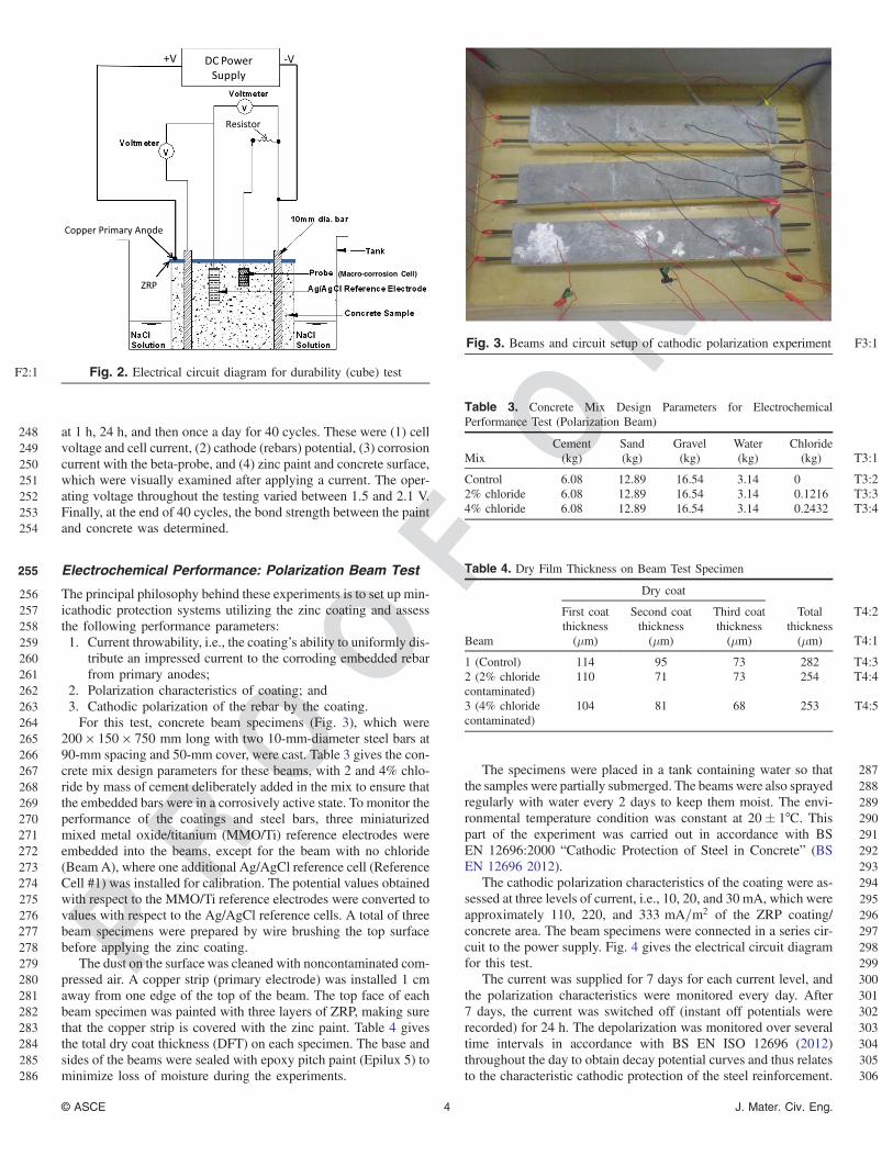
248 at 1 h, 24 h, and then once a day for 40 cycles. These were (1) cell249 voltage and cell current, (2) cathode (rebars) potential, (3) corrosion250 current with the beta-probe, and (4) zinc paint and concrete surface,251 which were visually examined after applying a current. The oper-252 ating voltage throughout the testing varied between 1.5 and 2.1 V.253 Finally, at the end of 40 cycles, the bond strength between the paint254 and concrete was determined.
255 Electrochemical Performance: Polarization Beam Test
256 The principal philosophy behind these experiments is to set up min-257 icathodic protection systems utilizing the zinc coating and assess258 the following performance parameters:259 1. Current throwability, i.e., the coating’s ability to uniformly dis-260 tribute an impressed current to the corroding embedded rebar261 from primary anodes;262 2. Polarization characteristics of coating; and263 3. Cathodic polarization of the rebar by the coating.264 For this test, concrete beam specimens (Fig. 3), which were265 200 × 150 × 750 mm long with two 10-mm-diameter steel bars at266 90-mm spacing and 50-mm cover, were cast. Table 3 gives the con-267 crete mix design parameters for these beams, with 2 and 4% chlo-268 ride by mass of cement deliberately added in the mix to ensure that269 the embedded bars were in a corrosively active state. To monitor the270 performance of the coatings and steel bars, three miniaturized271 mixed metal oxide/titanium (MMO/Ti) reference electrodes were272 embedded into the beams, except for the beam with no chloride273 (Beam A), where one additional Ag/AgCl reference cell (Reference274 Cell #1) was installed for calibration. The potential values obtained275 with respect to the MMO/Ti reference electrodes were converted to276 values with respect to the Ag/AgCl reference cells. A total of three277 beam specimens were prepared by wire brushing the top surface278 before applying the zinc coating.279 The dust on the surface was cleaned with noncontaminated com-280 pressed air. A copper strip (primary electrode) was installed 1 cm281 away from one edge of the top of the beam. The top face of each282 beam specimen was painted with three layers of ZRP, making sure283 that the copper strip is covered with the zinc paint. Table 4 gives284 the total dry coat thickness (DFT) on each specimen. The base and285 sides of the beams were sealed with epoxy pitch paint (Epilux 5) to286 minimize loss of moisture during the experiments.
287The specimens were placed in a tank containing water so that288the samples were partially submerged. The beams were also sprayed289regularly with water every 2 days to keep them moist. The envi-290ronmental temperature condition was constant at 20� 1°C. This291part of the experiment was carried out in accordance with BS292EN 12696:2000 “Cathodic Protection of Steel in Concrete” (BS293EN 12696 2012).294The cathodic polarization characteristics of the coating were as-295sessed at three levels of current, i.e., 10, 20, and 30 mA, which were296approximately 110, 220, and 333 mA=m2 of the ZRP coating/297concrete area. The beam specimens were connected in a series cir-298cuit to the power supply. Fig. 4 gives the electrical circuit diagram299for this test.300The current was supplied for 7 days for each current level, and301the polarization characteristics were monitored every day. After3027 days, the current was switched off (instant off potentials were303recorded) for 24 h. The depolarization was monitored over several304time intervals in accordance with BS EN ISO 12696 (2012)305throughout the day to obtain decay potential curves and thus relates306to the characteristic cathodic protection of the steel reinforcement.
(Macro-corrosion Cell)
F2:1 Fig. 2. Electrical circuit diagram for durability (cube) test
F3:1Fig. 3. Beams and circuit setup of cathodic polarization experiment
Table 3. Concrete Mix Design Parameters for ElectrochemicalPerformance Test (Polarization Beam)
T3:1MixCement(kg)
Sand(kg)
Gravel(kg)
Water(kg)
Chloride(kg)
T3:2Control 6.08 12.89 16.54 3.14 0T3:32% chloride 6.08 12.89 16.54 3.14 0.1216T3:44% chloride 6.08 12.89 16.54 3.14 0.2432
Table 4. Dry Film Thickness on Beam Test Specimen
T4:1Beam
Dry coat
Totalthickness(μm)
T4:2First coatthickness(μm)
Second coatthickness(μm)
Third coatthickness(μm)
T4:31 (Control) 114 95 73 282T4:42 (2% chloride
contaminated)110 71 73 254
T4:53 (4% chloridecontaminated)
104 81 68 253
© ASCE 4 J. Mater. Civ. Eng.
PROOF
ONLY
307 Experimental Results and Discussion
308 The results of the experimental works investigating the conduct-309 ance, adhesion, environmental durability, and electrochemical char-310 acteristics of ZRP to perform as an anode for the impressed current311 cathodic protection system to mitigate the corrosion of reinforce-312 ments in chloride-contaminated concrete are summarized and dis-313 cussed subsequently.
314 Conductance (Cross-Film Resistance)
315 The cross-film resistances were measured after each coating appli-316 cation using a digital multimeter until the resistance showed little317 change in values with further coating application. Data for the318 cross-film resistance against the number of coats applied were stat-319 istically analyzed using the R2 factor to assess the trend. The results320 in Table 5 and Fig. 5 show that the cross-film resistance decreasing321 exponentially, and the optimum minimum resistance was obtained322 with three or four coats, i.e., with a coating thickness of between323 286 and 322 μm of DFT. A further number of coats, e.g., up to five324 coats plotted in Fig. 5, showed an insignificant reduction in cross-325 film resistance.
326 Adhesion Strength
327 The initial test program identified that the ZRP coating used had328 good adhesion properties to the concrete substrate. The average val-329 ues ranges between 3.11 and 1.78 MPa for the concrete mix with a330 low water-cement ratio (w=c ¼ 0.50) and for the concrete mix with331 a high water-cement ratio (w=c ¼ 0.80), respectively. These tests332 were carried out within 48 h following drying of the final coat.333 The tests results obtained after allowing the paint to age for 56 days334 in total, i.e., 2 days for paint coats to dry plus 14 days of initial335 testing plus 40 days in the environmental chamber, for both low336 and high w/c concrete showed some increase in bond strength337 for both the low w/c concrete (average value was 3.35 MPa) and338 high w/c concrete (average value was 2.53 MPa) (Table 6). Detailed339 study on the failure mode(s) of ZRP applied on the concrete surface
340was outside the scope of the present investigations; however, the341adhesive strength values quoted in this evaluation are the values342with a failure criterion in which the area of fracture is greater than34315% with respect to failure between the substrate and coating. The344results to assess the effect of three different levels of surface rough-345ness on the adhesion strength of ZRP coating indicated that HR, in346which some aggregates were exposed, to MR, in which mainly the
F4:1 Fig. 4. Electrical circuit diagram for polarization (beam) test
Table 5. Summary Table of Cross-Film Resistance Measurement
T5:1Parameter HB 1(a) HB 1(b) HB 2 HB 3
T5:2DFT by measurement(μm)
286 296 322 301
T5:3Optimum lowresistance (kΩ)
142 124 44 61
T5:4Environmentalcondition
Outdoor Indoor/outdoor TCP
T5:5Drying time (h) 2–3 Variable 24
0
100
200
300
400
500
600
700
0 1 2 3 4 5
CO
AT
ING
RE
SIST
AN
CE
(ko
hm)
NUMBER OF ZRP COATS ( 60µm DFT each)
HB 1(a)
HB 1(b)
HB 2
HB 3
F5:1Fig. 5. Coating resistance versus number of coats
© ASCE 5 J. Mater. Civ. Eng.
PROOF
ONLY
347 cement laitance layer was removed with little or no aggregates348 exposed, produced better bond strength than that obtained for the349 VHR profile, in which most of the aggregates were exposed.350 Various studies carried out in the United States and Canada for351 the TS zinc/concrete interface to investigate the adhesion mecha-352 nism(s), which included the scanning electron microscopy (SEM)353 and metallographic examinations, confirmed that the adhesion354 of TS zinc coating on the concrete surface is purely mechanical355 (Covino et al. 2002). Similar studies with ZRP was outside the356 scope of the present investigations, but the application of both357 TS zinc and ZRP coating results in producing a layer of pure zinc358 on the concrete substrate with the contra distinction that the dep-359 osition of a solid zinc layer on a concrete surface and inside con-360 crete is because of solvent evaporation rather than solidification of361 molten zinc affecting the cold concrete surface, as is the case for362 TS zinc coating. On the basis of the fact that the ZRP is applied363 in a liquid form, it is likely that the paint will penetrate the con-364 crete surface and solidified. It is therefore likely that the bond is365 a chemical/mechanical one, with the physical interlock occurring366 in the cement pore. Subsequent exploratory examination of the367 concrete/ZRP interface under SEM (Figs. 6 and 7) showed that368 the ZRP has definitely penetrated deep into the concrete surface.369 The total thickness of ZRP, i.e., the light gray area in the photo-370 micrograph, appeared to be approximately 400 μm, but the mea-371 sured coating thickness on the concrete was between 253 and372 282 μm into the concrete matrix, as shown in Fig. 5. This suggested373 that ZRP penetration into the concrete matrix is approximately374 120–150 μm. However, further investigation is required to identify375 the interfacial chemistry of ZRP.376 A considerable amount of technical information is available in377 the literature for the interfacial chemical and electrochemical reac-378 tions at the TS zinc coating and concrete. The interfacial chemical379 and electrochemical reactions at the ZRP coating and concrete are380 considered to be similar to those identified by the studies carried381 out in the Untied States and Canada for the TS zinc/concrete inter-382 face (Covino et al. 2002). This is because of one common factor for383 both TS zinc and ZRP that a solid and pure zinc layer formed on the384 concrete substrate. When zinc is used as an anode for the CP sys-385 tem, either the galvanic mode or ICCP mode, the reaction steps are
Zn → Zn2þ þ 2e− ð1Þ
Zn2þ þ 2H2O → ZnðOHÞ2 þ H2 ð2Þ
ZnðOHÞ2 → ZnOþ H2O ð3Þ386 At the cathode, i.e., rebar, the usual reaction is
O2 þ 2H2Oþ 4e− → 4OH− ð4Þ387 The preceding anodic reactions lead to the formation of zinc388 minerals, such as zinc oxide ðZnOÞ=ZnðOHÞ2, followed by secon-389 dary mineralization when combined with other constituents of390 the environment, such as chloride, sulphate, or carbonate ions or
391minerals in the cement paste to form complex minerals, such as392zinc hydroxycarbonate, zinc hydroxychloride, and zinc hydroxy-393sulphate. With the passage of time, the more stable of these min-394erals will predominate over the less stable minerals in the Zn oxide395layer, which is likely to precipitate at the anode (zinc)-concrete in-396terface. The zinc corrosion products, particularly zinc oxychloride397and zinc oxysulphate, are formed by electromigration of chloride398and sulphate ions from within the concrete to the anode (Covino399et al. 2002). Further, as zinc ions migrate into concrete, a reaction400zone is developed in the cement paste, with zinc replacing Ca and401forming a (Ca, Zn) aluminosilicate. All these may affect the bond402strength of the zinc coating, leading to premature failure of the
Table 6. Bond Strength Results With and Without CP under Environmental Conditions and Comparison with Other Anode Systems
T6:1 Anode typeAdhesion strengthwithout CP (MPa)
Adhesion strengthwith CP (MPa) Comments
T6:2 ZRP coating 1.65 2.26 Strength increased after 40 cycles of environmentalexposure at 50°C, 90% HR (Reference is present work)
T6:3 TS zinc coating 1.28–2.29 Up to 3.5 Wetting and drying cycles. (Covino et al. 2002)T6:4 Conductive paint 1.5 (average) — Reference is HA specifications, U.K. (Chess and Broomfield 2003)T6:5 Cementitious overlay 1.5 — —T6:6 Conductive overlay 3.8 — Reference Badische Anilin- und Soda-Fabrik (BASF) chemicals
F7:1Fig. 7. SEM photomicrograph of ZRP specimen
F6:1Fig. 6. Polarization and potential shift over 40 cycles of environmentalF6:2test
© ASCE 6 J. Mater. Civ. Eng.
PROOF
ONLY
403 anode. However, as discussed in the next section, the results ob-404 tained after 40 cycles of accelerated testing in an environmental405 chamber with an applied CP current density of 440 mA=m2, which406 is four times the current density applied to the anode recommended407 in the National Association of Corrosion Engineers (NACE) stan-408 dard and in accordance to BS EN 12696 or 200 times the current409 density used in the Oregon DOT specification, showed some in-410 crease in bond strength (Covino et al. 2002).
411 Environmental Durability
412 The durability, i.e., anode life, and effective performance of the zinc413 coating, both TS zinc or ZRP, largely depends on adhesion (bond414 strength) between the anode and concrete, which in turn is affected415 by various factors, such as environmental exposure conditions,416 e.g., humidity, temperature, and chloride, concrete surface prepa-417 rations, and, more importantly, the chemical/electrochemical reac-418 tions at the zinc-concrete interface because of application of the419 CP current. The durability of zinc anodes can be defined in terms420 of electrochemical aging, as determined from the total electrical421 charge passed until the adhesion (bond) strength of the zinc coating422 decreased to zero (Covino et al. 2002).423 The data collected at the end of the durability testing in the envi-424 ronmental chamber show that the total charge passed in 40 cycles425 was calculated to 427 A-h=m2. In accordance with the NACE426 standard TM0294 (NACE 2007), the total charge density of
42738,500 A-h=m2 of the actual anode surface area equates to a serv-428iceable anode life of 40 years if operated at a current density of429110 mA=m2 of the anode surface for 40 years (NACE 2007). This430represents a predicted anode life of approximately 20 years at a431normal operating current density of 10 mA=m2 or some 100 years432at 2.2 mA=m2, as recommended by the Oregon DOT specification433(Covino et al. 2002).434The results of the environmental testing given in Tables 7 and 8435were recorded at a 20°C temperature and 50% humidity, without436and with application of CP. The polarized potentials and CP current437of the reinforcements monitored during the 40 cycle environmental438testing (Fig. 6) showed increased levels of polarization on all cube439samples, and the results also showed that the higher the potential440shift, i.e., instant off polarized potential minus base corrosion po-441tential, the higher the chloride content in the concrete. The analysis442of the corrosion currents for the cube specimens, calculated from443the measurements using macrocell corrosion probes, show that the444average corrosion of rebars without CP increased with chloride445content from 46 to 57 μA for 0% Cl and 1–3.5% Cl, respectively,446as expected. This is in line with the increasing risk of corrosion with447increasing levels of chloride in the concrete, as indicated by the448measured corrosion potentials. Similarly, with CP, the higher the449measured average flow of corrosion currents, rather than the pro-450tection current, from the ZRP anode system, the higher the chloride451content in the concrete. At the end of 40 cycles, i.e., 40 days, of452the durability test, the adhesion strength of the ZRP concrete was
Table 7. Corrosion Potential versus Silver/Silver Chloride Reference Electrode and Corrosion Current of Rebar in Cube Samples Without CP
T7:1 Number ofdays recorded
Cube A (no chloride content) Cube B (1% chloride content) Cube C (3.5% chloride content)
T7:2 Corrosionpotential (mV)
Corrosioncurrent (μA)
Corrosionpotential (mV)
Corrosioncurrent (μA)
Corrosionpotential (mV)
Corrosioncurrent (μA)
T7:3 1 −306 −38 −358 −39.5 −370 −39T7:4 2 −318 −47 −368 −42 −405 −39.5T7:5 3 −298 −40 −361 −40 −417 −37T7:6 4 −279 −49.5 −342 −44 −428 −42T7:7 5 −271 −47 −357 −48.5 −453 −53.5T7:8 6 −283 −47.5 −354 −52 −461 −52.5T7:9 7 −248 −48 −312 −55 −414 −50
T7:10 8 −259 −40 −368 −59 −434 −49.5T7:11 9 −273 −49 −363 −63 −438 −53.5T7:12 10 −289 −53 −357 −72 −440 −62T7:13 11 −292 −48 −344 −68 −412 −67T7:14 12 −301 −47 −343 −75 −471 −73T7:15 13 −312 −42 −396 −73.5 −449 −82T7:16 14 −318 −49 −356 −74 −453 −93
Table 8. Corrosion Potential versus Silver/Silver Chloride Reference Electrode and Corrosion Current of Rebar in Cube Samples with CP
T8:1 Numberof days
Cube A (no chloride) Cube B (1% chloride) Cube C (3.5% chloride)
T8:2 Polarized potentialwith respect toAg/AgCl (mV)
Calculated macrocellcorrosion
current (μA)
Polarized potentialwith respect toAg/AgCl (mV)
Calculated macrocellcorrosion
current (μA)
Polarized potentialwith respect toAg/AgCl (mV)
Calculated macrocellcorrosion
current (μA)
T8:3 1 −353 −49.5 −433 −73.5 −498 −93.5T8:4 7 −315 −52 −510 −75 −453 −98T8:5 8 −355 −52.5 −529 −74.5 −461 −98T8:6 16 −358 −53 −436 −75 −482 −97.5T8:7 24 −380 −52.5 −453 −75.5 −467 −98.5T8:8 32 −301 −52 −430 −76 −549 −98.5T8:9 40 −330 −53.5 −548 −76.5 −591 −98
Note: The measured base potential for Cubes A–C was −289, −356, and −435 mV, respectively. The calculated potential shift at the end of 40 cycles forCubes A–C was 41, 192, and 159 mV, respectively.
© ASCE 7 J. Mater. Civ. Eng.
PROOF
ONLY
453 determined, and the results given in Table 9 indicated a significant454 increase in bond strength, possibly because of electrochemical455 aging.
456 Electrochemical Performance: Polarization Tests
457 Tables 10 and 11 summarize the results of the investigation to assess458 various electrochemical parameters. The results showed that the459 ZRP anode system was capable of polarizing the steel rebar cathod-460 ically, and the potential shift, i.e., instant off polarized potential461 minus base corrosion potential, values were found to be increasing462 with an increased applied current density on the anode the higher463 the extent of polarization. As expected, the higher the levels of464 polarization, the higher the chloride content in the concrete.465 The cumulative charge in kilocoulombs=m2 passed across the466 anode per unit area during the accelerated ICCP test to assess467 durability is calculated to be approximately 377 kC=m2 (Table 10).468 This equates to 18.2 μm of Zn dissolved. These data can then be469 used to estimate the design life of the ZRP anode in terms of Zn470 anode consumption and/or electrochemical aging.471 Adhesion tests, i.e., pull-off tests using sellotape, at the end of472 electrochemical testing showed no decrease in the bond strength473 but some increase in bond. Table 11 gives the polarized potentials474 of the concrete beam specimens with 0, 2, and 4% chloride, mea-475 sured at a distance of 200 mm (Reference Cell #1), 400 mm476 (Reference Cell #2), and 600 mm (Reference Cell #3) away from477 the primary anode connections for the applied current density of478 104 mA=m2. Similar sets of data were obtained at an applied cur-479 rent density of 208 and 313 mA=m2. These electrochemical tests480 also showed that there is very little variation of polarized potential481 with distance from the primary anode. This suggest that the current482 throwability from the primary anode connection extends at least up483 to 600 mm without significant current attenuation and confirmed484 uniform current distribution. This suggests that the ZRP coating485 is capable of distributing the protection current uniformly.
486The data generated from this investigation not only provide use-487ful information with regard to the performance and suitability of488ZRP coatings as a promising anode for the ICCP system, but489the service life of the anode could be predicted in accordance with490the NACE standard TM0294 (NACE 2007). The ZRP coating used491as an ICCP or galvanic mode anode is a consumable anode,492whereas ICCP systems are designed to usually utilize nonconsum-493able anodes, such as MMO/Ti. Traditionally, the service life of con-494sumable anodes is determined using typical anode parameters and495can be expressed as follows:
Anode life ¼ ½Faraday consumption rate ðA-h=kgÞ=number of hours in a year� × anodemass ðin kgÞ× anode efficiency × utilization factor=
anode current in amperes
496However, this traditional approach to calculate the service life of497ZRP coating and also TS zinc coating applied on the concrete sur-498face may prove to be inappropriate. The service life for the surface-499applied zinc anode would, more importantly, depend on the long-500term adhesion (bond) strength, which in turn, among other factors,501is strongly affected by the chemical/electrochemical reaction502products at the zinc-concrete interface. However, for the design503calculations, the service life of ZRP, on the basis of charge in504kilo-coulombs=m2 passed across the anode per unit area, was found505to be well in excess of 20 years at a normal operating current506density of 10 mA=m2.
507Conclusions
508On the basis of the results of this investigation and the interpreta-509tion and discussions of the results, the following conclusions510are made:5111. The ZRP coating used had good adhesion properties to a con-512crete substrate. The adhesion values obtained were 3.5 and5131.65 MPa, with and without applied current, respectively.514The bond strength results showed that the strength value in-515creased between zinc paint and concrete when the current516was applied for 40 days. This increase in bond strength is517probably because of the chemical/electrochemical reactions518between ZRP and cement.
Table 9. Bond Strength Test Results of All Three Cubes before and afterApplied Current (Durability Test)
T9:1 SampleTest results beforecurrent (MPa)
Test results aftercurrent (MPa)
T9:2 A 1.50 2.0T9:3 B 1.85 2.5T9:4 C 1.60 2.3
Table 11. Summary Results: Polarization Beam Specimen with 0, 2, and 4% Chloride at 104 mA=m2
T11:1 Specimen
Polarized Potentials with respect to Ag/AgCl after 7 days at applied current density of 104 mA=m2
T11:2 Reference Cell # 1, 200 mmfrom primary anode connection
Reference Cell # 2, 400 mmfrom primary anode connection
Reference Cell # 3, 600 mmfrom primary anode connection
T11:3 Beam with 0% chloride −385 −387 −389T11:4 Beam with 2% chloride −442 −442 −453T11:5 Beam with 4% chloride −501 −501 −453
Table 10. Summary Results for Total Charge Passed: Polarization Beam Specimen with 0% Chloride
T10:1 BeamApplied
current (mA)Applied currentdensity (mA=m2)
Elapsed time(days)
Total chargepassed (kC=m2)
Cumulative chargepassed (kC=m2)
Amount of Zn dissolved,kC=m2 × 0.048 (μm)
T10:2 1 (no chloride) 10 104 7 62.9 377.4 18.12T10:3 20 208 7 125.8T10:4 30 313 7 188.5
Note: Similar results were obtained with other chloride content.
© ASCE 8 J. Mater. Civ. Eng.
PROOF
ONLY
519 2. Accelerated environmental test results showed that the ZRP520 coating was capable of withstanding/supporting high levels521 of current. More than 300 mA=m2 CP current was applied522 for a total of 40 cycles without showing any evidence of coat-523 ing deterioration or loss of bond strength.524 3. In accordance with NACE standard TM0294 and on the525 basis of data obtained from accelerated environmental testing,526 the service life of the ZRP coating was estimated to be well in527 excess of 20 years at an applied current density of 10 mA=m2.528 However, the service life of ZRP or TS zinc coating would,529 more importantly, depend on the chemical/electrochemical530 reactions at the zinc coating–concrete interface and the nature531 and extent of the reaction products, i.e., the primary and sec-532 ondary mineral deposits because of dissolution of zinc as the533 CP anode, which in turn affects the adhesion strength of the534 coating to concrete substrate.535 4. Electrochemical tests also showed that there is very little var-536 iation of polarized potential with distance from the primary537 anode. This suggests that the current throwability from the pri-538 mary anode connection extends at least up to 600 mm without539 significant current attenuation and uniform current distribution.
540 Acknowledgments
541 The authors wish to express their gratitude and sincere appreciation542 to the laboratory staff of Coventry University.
543 References
544 Abreu, C. M., Espada, L., Izquierdo, M., Merino, P., and Novoa, X. R.545 (1997). “Zinc rich powder coatings in sea water.” Eurocorr’96,546 L. Fedrizzi and P. L. Bonora, eds., Vol. 20, Acropolis, Nice, France, 23.547 Abreu, C. M., Izquierdo, M., Keddam, M., Novoa, X. R., and Takenouti, H.548 (1996). “Electrochemical behaviour of zinc- rich epoxy paints in 3%549 NaCl solution.” Electrochim. Acta, 41(15), 2405–2415.550 Amo, B. D., and Giùdice, C. A. (1990). “Influence of some variables551 on behaviour of zinc-rich paints based on ethyl silicate and epoxy552 binders.” Proc., 6th Int. Corrosion Congress, Associazione Italiana553 di Metallurgia, Florence, 347.554 Apostolos, J. A. (1984). “Cathodic protection of reinforced concrete by555 using metallized coatings and conductive paints.” Transportation556 Research Record 926, Transportation Research Board, Washington,557 DC, 222–228.558 Armas, R. A., Gervasi, C. A., Sarli, A. D., Real, S. G., and Vilche, J. R.559 (1992). “Zinc-rich paints on steel in artificial seawater by electrochemi-560 cal impedance spectroscopy.” Corrosion, 48(5), 379–383.561 British Standards Institution. (2000). “Concrete—Part 1: Specification,562 performance, production and conformity.” BS EN 260-1BSI, London.563 British Standards Institution. (2012). “Cathodic protection of steel in564 concrete.” BS EN ISO 12696, London.565 Bullard, S. J., Cramer, S., Covino, B. (2009). “Final Rep., effectiveness of566 cathodic protection, SPR 345.” National Energy Technology Labora-567 tory, Albany, OR.
568Chess, P.M., and Broomfield, J. P. (2003). Cathodic protection of steel in569concrete, CRC Press.570CIRIA. (1993). “Standard test for repair materials and coatings for571concrete, Part 1: Pull-off tests.” CIRIA technical note 139, London.572Covino, B. S., Jr., Cramer, S. D., Bullard, S. J., Holcomb, G. R., Russel,573J. H., and Collins, W. K. (2002). “Performance of zinc anodes for574cathodic protection of reinforced concrete bridges.” Final Rep. SPR575364, Oregon Department of Transportation Research Group, FHWA,576Washington DC.577Das, S. C. (2012). “Zinc rich paint as anode system for cathodic protection578(cp) of reinforced concrete structures and development of corrosion/cp579monitoring probes.” Ph.D. thesis, Coventry Univ., Coventry, U.K.580Elcometer. (2004). Elcometer 106 scale 6: Coatings on concrete adhesion581tester and concrete tensile tester: operating instructions, Belgium.582Feliu, S., Barajas, R., Bastidas, J. M., and Morcillo, M. (1989). “Mecha-583nism of cathodic protection of zinc-rich paints by electrochemical584impedance spectroscopy.” J. Coating Technol., 61(775), 63–69.585Fragata, F. L., Sebrão, M., and Serra, E. T. (1987). “The influence of par-586ticle size and metallic zinc content in the behaviour of zinc-rich paints.”587J. Coatings Technol., 60(751), 12–16.588Hare, C. H. (1998). “Mechanisms of corrosion protection with surface589treated wollastonite pigments.” J. Protective Coatings, 14(3), 47–82.590Kepler, J. L., Darin, D., and Lock, C. E. (2000). “Evaluation of corrosion591protection methods for reinforced concrete highway structures.” Struc-592tural engineering and engineering materialsSM Rep. No. 58, Univ. of593Kansas Center for Research, Lawrence, KS.594Lindquist, S. A., Méssaros, L., and Svenson, L. (1985). “Aspects of595galvanic action of zinc-rich paints. Electrochemical investigation of596eight commercial primers.” Oil Colour Chem. Assoc., 68, 10.597Morcillo, M., Barajas, R., Feliu, S., and Bastidas, J. M. (1990). “Electro-598chemical behavior of zinc-rich coatings.” J. Mater. Sci., 25(5),5992441–2446.600NACE (National Association of Corrosion Engineers). (2007). NACE601TM0294 test method, accelerated life testing of zinc anode for steel602reinforced concrete, Houston.603National Cooperative Highway Research Program (NCHRP). (2009).604“Synthesis 398, Cathodic protection for life extesion of existing rein-605forced concrete bridge elements.” Report No. 398, Transportation606Research Board, Washington DC.607Pereira, D., Scantlebury, J. D., Ferreira, M. G. S., and Almeida, M. C.608(1990). “The application of electrochemical measurements to the study609and behaviour of zinc–rich coatings.” Corros. Sci., 30(11), 1135–1147.610Sagüés, A. A., and Powers, R. G. (1996). “Sprayed-zinc sacrificial anodes611for reinforced concrete in marine service.” Corrosion, 52, 508.612Strategic Highways Research Program. (1993). “Cathodic protection of613reinforced concrete bridge elements: A state-of the-art report.” SHRP-614S-337, Eltech Research Corporation, National Research Council,615Washington DC.616Vilche, J. R., Bucharsky, E. C., and Giúdice, C. A. (2002). “Application of617EIS and SEM to evaluate the influence of pigment shape and content in618ZRP formulations on the corrosion prevention of naval steel.” Corros.619Sci., 44(6), 1287–1309.620Wicks, Z. W., Jr., Jones, F. N., and Pappas, S. P. (1994). Organic coatings:621Science and technology, 2nd Ed., Wiley, New York.622Zhang, X. G. (1996). Corrosion and electrochemistry of zinc, Plenum,623New York.
© ASCE 9 J. Mater. Civ. Eng.

![Cathodic Protection - An Overview [Recovered] · Typical uses and comparisons are detailed in the sections below. SACRIFIIAL ANODE CATHODIC PROTECTION In this type of application](https://static.fdocuments.in/doc/165x107/5cb5190788c99310568c14c9/cathodic-protection-an-overview-recovered-typical-uses-and-comparisons-are.jpg)


![WP Cathodic Protection - galvatest.com · cathodic than it is. Install a protective zinc anode [(-) 1000 mV (as above)] to reverse the situation by repositioning the aluminium as](https://static.fdocuments.in/doc/165x107/5e6b3f993e616e42642853c2/wp-cathodic-protection-cathodic-than-it-is-install-a-protective-zinc-anode-.jpg)