Zimmer NexGen LPS-Flex Fixed Bearing Kneeprod- · 2 Zimmer ® NexGen LPS-Flex Fixed Bearing Knee...
13
Zimmer ® NexGen ® LPS-Flex Fixed Bearing Knee Surgical Technique Designed to accomodate resumption of high-flexion daily activities
Transcript of Zimmer NexGen LPS-Flex Fixed Bearing Kneeprod- · 2 Zimmer ® NexGen LPS-Flex Fixed Bearing Knee...

Zimmer®
NexGen®
LPS-Flex Fixed Bearing Knee
Surgical Technique
Designed to accomodate resumption of high-flexion daily activities

Zimmer® NexGen® LPS-Flex Fixed Bearing Knee Surgical Technique 1
Zimmer® NexGen® LPS-Flex Fixed Bearing Knee Surgical Technique
Table of Contents
Introduction 2
Patient Selection 3
Preoperative Conditioning 3
Preoperative Planning 3
Surgical Technique 4Incision and Exposure 4
PCL Resection 4
Soft Tissue Releases 4
Varus Release 4
Valgus Release 5
Tibial Preparation 6
Femoral Preparation 6
Flexion Extension Gaps 7
Patella Preparation 8
Finishing the Tibia 8
Trial Reduction 8
Implantation 8
Closure 11
Rehabilitation Protocol 11
Zimmer® NexGen® LPS-Flex Fixed Bearing Knee Surgical Technique2
Introduction
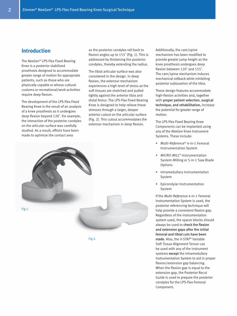
The NexGen® LPS-Flex Fixed Bearing Knee is a posterior stabilized prosthesis designed to accommodate greater range of motion for appropriate patients, such as those who are physically capable or whose cultural customs or recreational/work activities require deep flexion.
The development of the LPS-Flex Fixed Bearing Knee is the result of an analysis of a knee prosthesis as it undergoes deep flexion beyond 120˚. For example, the interaction of the posterior condyles on the articular surface was carefully studied. As a result, efforts have been made to optimize the contact area
as the posterior condyles roll back to flexion angles up to 155˚ (Fig. 1). This is addressed by thickening the posterior condyles, thereby extending the radius.
The tibial articular surface was also considered in the design. In deep flexion, the extensor mechanism experiences a high level of stress as the soft tissues are stretched and pulled tightly against the anterior tibia and distal femur. The LPS-Flex Fixed Bearing Knee is designed to help relieve these stresses through a larger, deeper anterior cutout on the articular surface (Fig. 2). This cutout accommodates the extensor mechanism in deep flexion.
Additionally, the cam/spine mechanism has been modified to provide greater jump height as the knee prosthesis undergoes deep flexion between 120˚ and 155˚. The cam/spine mechanism induces mechanical rollback while inhibiting posterior subluxation of the tibia.
These design features accommodate high-flexion activities and, together with proper patient selection, surgical technique, and rehabilitation, increase the potential for greater range of motion.
The LPS-Flex Fixed Bearing Knee Components can be implanted using any of the NexGen Knee Instrument Systems. These include:
• Multi-Reference® 4-in-1 Femoral Instrumentation System
• MICRO-MILL® Instrumentation System-Milling or 5-in-1 Saw Blade Options
• Intramedullary Instrumentation System
• Epicondylar Instrumentation System
If the Multi-Reference 4-in-1 Femoral Instrumentation System is used, the posterior referencing technique will help provide a consistent flexion gap. Regardless of the instrumentation system used, the spacer blocks should always be used to check the flexion and extension gaps after the initial femoral and tibial cuts have been made. Also, the V-STAT® Variable Soft Tissue Alignment Tensor can be used with any of the instrument systems except the Intramedullary Instrumentation System to aid in proper flexion/extension gap balancing. When the flexion gap is equal to the extension gap, the Posterior Recut Guide is used to prepare the posterior condyles for the LPS-Flex Femoral Component.
Fig 1.
Fig 2.

Zimmer® NexGen® LPS-Flex Fixed Bearing Knee Surgical Technique 3
Fig 3. Thigh-calf angle
Meets selection criteria<90°
>90°Does not meet
selection criteria
Patient Selection
The LPS-Flex Fixed Bearing Knee should be used with patients capable of higher flexion to optimize its potential benefits. A common view among potential orthopaedic surgeons is that preoperative range of motion is a good indicator of postoperative range of motion. In determining the appropriateness of this implant for any patient, careful consideration should be given to the following criteria for patient selection.
1. The patient should be capable of reaching 120˚ of flexion preoperatively, with a reasonable probability, in the surgeon’s judgement, of achieving a range greater than 130˚ postoperatively.
2. The patient should have a need and desire to perform deep-flexion activities. This need is often dictated by cultural background where practices such as frequent kneeling for prayer, sitting “cross-legged,” and squatting are common. Also, certain hobbies and recreational activities, such as gardening, bowling, or golfing, may require high-flexion capabilities.
3. The patient should have a thigh-calf index of less than 90˚ (Fig. 3).
4. The patient should have stable and functional collateral ligaments.
5. If the patient has an angular deformity, it should be less than 20 .̊ Keep in mind that it is more difficult to achieve ligament balance in these patients. And, in patients with severe deformity, consider the patient expectation for achieving high flexion.
6. The patient should not be obese.
It is also important to consider the length of time the patient has not performed high-flexion activities.
Preoperative Conditioning
To help prepare the patient for surgery, it may be helpful for the patient to perform mobility exercises to prepare the ligaments and muscles for the postoperative rehabilitation protocol.
Preoperative Planning
Use the template overlay (available through your Zimmer representative) to help determine the angle between the anatomic axis and the mechanical axis. This angle should be reproduced intraoperatively.
Use the various templates to approximate the appropriate component sizes. The final sizes must be determined intraoperatively; therefore, larger and smaller sizes should be available during surgery.
Select the instrumentation system and technique that will be used to implant the LPS-Flex Fixed Bearing Knee Components. Any of four instrumentation systems and techniques can be used: the Multi-Reference 4-in-1 Femoral Instrumentation System, the MICRO-MILL Instrumentation System with Milling or 5-in-1 Saw Blade Options, the Intramedullary Instrumentation System, or the Epicondylar Instrumentation System. The spacer blocks available with these instrument systems should always be used to check the flexion and extension gaps.
In addition, the V-STAT Variable Soft Tissue Alignment Tensor can be used with any of the instrumentation choices except the Intramedullary Instrumentation System.

Zimmer® NexGen® LPS-Flex Fixed Bearing Knee Surgical Technique4
LaxTensed
Contracture
Fig 5.
Surgical Technique
Surgical technique is an important factor to consider when attempting to maximize range of motion in total knee arthroplasty (TKA). Close attention must be paid to balancing the flexion and extension gaps, clearing posterior osteophytes, releasing the posterior capsule, and reproducing the joint line.
Although the joint line often changes as a result of a posterior cruciate substituting procedure, it is important that an attempt be made to maintain the joint line when high flexion is a priority. Depending on the degree, altering the joint line can cause patellofemoral issues and limit the degree of flexion. An elevated joint, for example, can cause tibiofemoral tightness in roll-back and thus restrict flexion.1
When using the gap technique, it is possible that the joint line may be moved proximally, especially if there is a preoperative flexion contracture or if the selected femoral component is smaller than the A/P dimension of the femur. The alteration of the joint line can be minimized by accurately measuring for the femoral component size and performing a posterior capsulotomy to correct flexion contractures.
Incision and ExposureThe medial parapatellar approach is recommended for the LPS-Flex Fixed Bearing Knee. With the patient in the supine position and the knee slightly flexed, make a straight midline incision. Begin the incision medial to the quadriceps tendon and 3cm-5cm above the superior pole of the patella. Extend it distally to below the level of the tibial tubercle (Fig. 4). Then make a medial parapatellar capsular incision.
PCL ResectionRemoving the PCL will make it easier to balance the collateral ligaments. Because the LPS-Flex Fixed Bearing Knee Prosthesis is a posterior cruciate ligament substituting design, it is necessary to completely resect the PCL. Any residual stump of the PCL may impinge in the cam/spine mechanism causing pain and limited motion. Resection of the PCL may influence the height of the flexion and extension gaps. Check for symmetry and balance of the flexion and extension gaps. Any differences in the gaps must be addressed.
Soft Tissue ReleasesThe objective of this procedure should be to distribute contact stresses across the artificial joint as symmetrically as possible.2 This requires the creation of equal and symmetrical flexion and extension gaps.
Varus ReleaseTo correct most fixed varus deformities (Fig. 5), progressively release the tight medial structures until they reach the length of the lateral supporting structures. The extent of the release can be monitored by inserting laminar spreaders within the femorotibial joint
Fig 4.
Zimmer® NexGen® LPS-Flex Fixed Bearing Knee Surgical Technique 5
Contracture
Tensed
Lax
Fig 6.
and judging alignment with a plumb line. To facilitate the release, excise osteophytes from the medial femur and tibia. These osteophytes tent the medial capsule and ligamentous structures, and their removal can produce a minimal correction before beginning the soft tissue release. Posteromedial osteophytes may need to be removed after the proximal tibia is resected.
With the knee in extension, elevate a subperiosteal sleeve of soft tissue from the proximal medial tibia, including the deep medial collateral ligament, superficial medial collateral ligament, and insertion of the pes anserinus tendons. Continue the elevation with a periosteal elevator to free the posterior fibers. To improve exposure during the release, retract this subperiosteal sleeve using a Homan retractor.
Release the insertion of the semimembranosus muscle from the posteromedial tibia, and concurrently remove posterior osteophytes.
Continue the release distally on the anteromedial surface of the tibia for 8cm-10cm and strip the periosteum medially from the tibia. This should be sufficient for moderate deformities. For more severe deformities, continue subperiosteal stripping posteriorly and distally.
When varus malalignment is present with a flexion contracture, it may be necessary to release or transversely divide the posterior capsule.
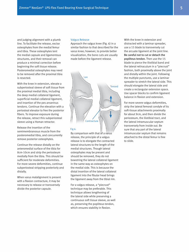
Valgus ReleaseApproach the valgus knee (Fig. 6) in a similar fashion to that described for the varus knee; however, to provide better visualization, the bone cuts are usually made before the ligament release.
By comparison with that of a varus release, the principle of a valgus release is to elongate the contracted lateral structures to the length of the medial structures. Though lateral osteophytes may be present and should be removed, they do not bowstring the lateral collateral ligament in the same way as osteophytes on the medial side. This is because the distal insertion of the lateral collateral ligament into the fibular head brings the ligament away from the tibial rim.
For a valgus release, a “piecrust” technique may be preferable. This technique allows lengthening of the lateral side while preserving a continuous soft tissue sleeve, as well as, preserving the popliteus tendon, which ensures stability in flexion.
With the knee in extension and distracted with a laminar spreader, use a 15 blade to transversely cut the arcuate ligament at the joint line. Be careful not to cut or detach the popliteus tendon. Then use the 15 blade to pierce the iliotibial band and the lateral retinaculum in a “piecrust” fashion, both proximally above the joint and distally within the joint. Following the multiple punctures, use a laminar spreader to stretch the lateral side. This should elongate the lateral side and create a rectangular extension space. Use spacer blocks to confirm ligament balance in flexion and extension.
For more severe valgus deformities, strip the lateral femoral condyle of its soft-tissue attachments proximally for about 9cm, and then divide the periosteum, the iliotibial tract, and the lateral intramuscular septum transversely from inside out. Be sure that any part of the lateral intramuscular septum that remains attached to the distal femur is free to slide.

Zimmer® NexGen® LPS-Flex Fixed Bearing Knee Surgical Technique6
Tibial PreparationUsing the selected instrumentation system, and following the appropriate technique for that system, establish the tibial cutting platform and resect the proximal tibia. Some PS surgeons may prefer to cut the tibia with a 3˚-5˚ posterior slope that matches the preoperative slope of the tibia. Excessive posterior slope can increase the likelihood of the femoral component contacting the anterior portion of the articular surface spine.
Femoral PreparationWhen sizing the femoral component, it is preferable to select the closest size. With the large selection of available femoral component sizes for the LPS-Flex Knee, it is possible to choose a size that is within 2mm of the measured anatomy. However, depending on the situation, selecting the closest size could mean either upsizing or downsizing. Because the LPS-Flex Knee is a posterior stabilized design, surgeons should first consider upsizing. By doing this, they maintain the option to downsize if the knee is too tight in flexion with the larger size.
Prepare the femur as per the MIS Mini-Incision Multi-Reference 4-in-1 technique or the MIS Mini-Incision IM technique. Alternatively, the MIS Quad-Sparing™ technique may also be utilized. When choosing the 3˚ flexion cut in the 4-in-1 technique, excessive flexion in the distal femoral cut can increase the likelihood of the femoral component contacting the anterior portion of the articular surface spine. If a size A or B femoral component is chosen, do not drill the distal femoral post holes at this time. Size A and B femoral components have smaller pegs. The holes should be drilled using the size A/B Femoral Peg Drill and the Posterior Recut Guide.
Using a posterior referencing technique will help ensure an appropriate flexion gap as the technique results in a predictable and consistent resection of the posterior condyles. The resected portion of the medial femoral condyle should be at least 9mm-10mm, while the resected portion of the lateral femoral condyle will be dictated by the degree of femoral component rotation. If an anterior referencing technique is used, be aware of the amount of posterior condylar resection, since the variable cut is now posterior. Avoid resection greater than 10mm from the posterior medial condyle.
It is necessary to externally rotate the femoral component in order to create a symmetrical flexion space. The transepicondylar axis provides a reproducible method of setting femoral rotation and allows precise positioning of the femoral component. The anteroposterior axis of the femur provides an additional rotational landmark. While 3˚ of external rotation of the femoral component may be
appropriate for a varus knee, 5˚ is more appropriate for a valgus deformity of 10˚-20˚, and 7˚ may be necessary for a valgus deformity greater than 20˚ accompanied by patella subluxation. The critical goal is to create a rectangular and symmetrical flexion gap between the femur and tibia.
When establishing the mediolateral position of the femoral component, it is recommended to lateralize the component to help improve patellar tracking. Avoid positioning the component where it overhangs the bone as this may restrict flexion.
With the knee in flexion, remove posterior osteophytes with a 3/4-inch curve-on-flat osteotome (Fig. 7). Use a laminar spreader and the Posterior Femoral Retractor to improve exposure (Fig. 8).
Fig 8.Fig 7.
Zimmer® NexGen® LPS-Flex Fixed Bearing Knee Surgical Technique 7
Fig 10.
Fig 9.
Variable anterior femoral cut
Posterior reference point helps to provide a consistent flexion gap
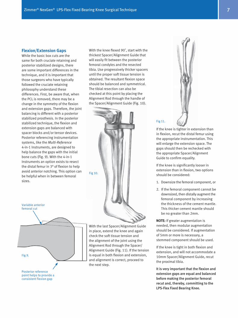
Flexion/Extension GapsWhile the basic box cuts are the same for both cruciate retaining and posterior stabilized designs, there are some important differences in the technique, and it is important that those surgeons who have typically followed the cruciate retaining philosophy understand these differences. First, be aware that, when the PCL is removed, there may be a change in the symmetry of the flexion and extension gaps. Therefore, the joint balancing is different with a posterior stabilized prosthesis. In the posterior stabilized technique, the flexion and extension gaps are balanced with spacer blocks and/or tensor devices. Posterior referencing instrumentation systems, like the Multi-Reference 4-in-1 Instruments, are designed to help balance the gaps with the initial bone cuts (Fig. 9). With the 4-in-1 Instruments an option exists to resect the distal femur in 3° of flexion to help avoid anterior notching. This option can be helpful when in between femoral sizes.
With the knee flexed 90˚, start with the thickest Spacer/Alignment Guide that will easily fit between the posterior femoral condyles and the resected tibia. Use progressively thicker spacers until the proper soft tissue tension is obtained. The resultant flexion space should be balanced and symmetrical. The tibial resection can also be checked at this point by placing the Alignment Rod through the handle of the Spacer/Alignment Guide (Fig. 10).
With the last Spacer/Alignment Guide in place, extend the knee and again check the soft tissue tension and the alignment of the joint using the Alignment Rod through the Spacer/Alignment Guide (Fig. 11). If the tension is equal in both flexion and extension, and alignment is correct, proceed to the next step.
If the knee is tighter in extension than in flexion, recut the distal femur using the appropriate instrumentation. This will enlarge the extension space. The gaps should then be rechecked with the appropriate Spacer/Alignment Guide to confirm equality.
If the knee is significantly looser in extension than in flexion, two options should be considered:
1. Downsize the femoral component, or
2. If the femoral component cannot be downsized, then distally augment the femoral component by increasing the thickness of the cement mantle. This thicker cement mantle should be no greater than 2mm.
NoTE: If greater augmentation is needed, then modular augmentation should be considered. If augmentation of 5mm or more is necessary, a stemmed component should be used.
If the knee is tight in both flexion and extension, and will not accommodate a 10mm Spacer/Alignment Guide, recut the proximal tibia.
It is very important that the flexion and extension gaps are equal and balanced before making the posterior femoral recut and, thereby, committing to the LPS-Flex Fixed Bearing Knee.
Fig 11.

Zimmer® NexGen® LPS-Flex Fixed Bearing Knee Surgical Technique8
Patella PreparationNoTE: If the surgeon determines that the condition of the patient’s patella is satisfactory, it is not necessary to resurface the patella. The geometry, depth, and length of the patellar grove on the NexGen Femoral Component accommodates the unresurfaced patella.
Using the desired patella preparation technique, resurface the articular surface of the patella. Be sure to determine the appropriate patella thickness. When drilling the peg holes for the patellar component, position the Patellar Drill Guide so as to medialize the patellar implant. (When the patella is everted, this means placing the guide on the lateral border.)
Finishing the TibiaSelect the proper size Tibial Sizing/Positioning Plate that provides the desired tibial coverage.
The tibia can be finished before the trial reduction if the implant position will be chosen based on anatomic landmarks. Alternatively, the sizing plate and provisionals can be used to perform a trial range of motion to aid in tibial position.
Fig 12.
Trial ReductionPlace the Femoral Provisional, the Tibial Plate Provisional, the Articular Surface Provisional, and the Patellar Provisional (if needed) onto the prepared bone surfaces.
A screw should be used to secure the Articular Surface Provisional onto the plate.
With all the provisional components in place, perform a complete range of motion (Fig. 12). Observe patellar tracking and tilt. If necessary, perform a lateral retinacular release.
Observe patellar tracking and tilt. If necessary, perform a lateral retincaular release.
ImplantationAfter the implants have been chosen, make one last check to ensure that the femoral, tibial, and articular surface components match. The femoral letter must match one of the letters on the articular surface carton. The tibial plate number must match one of the numbers indicated on the articular surface carton as indicated by the interchangeability chart.
Insert the appropriate size femoral and tibial components. Then use the Articular Surface Inserter to attach the appropriate tibial articular surface onto the plate.
Zimmer® NexGen® LPS-Flex Fixed Bearing Knee Surgical Technique 9
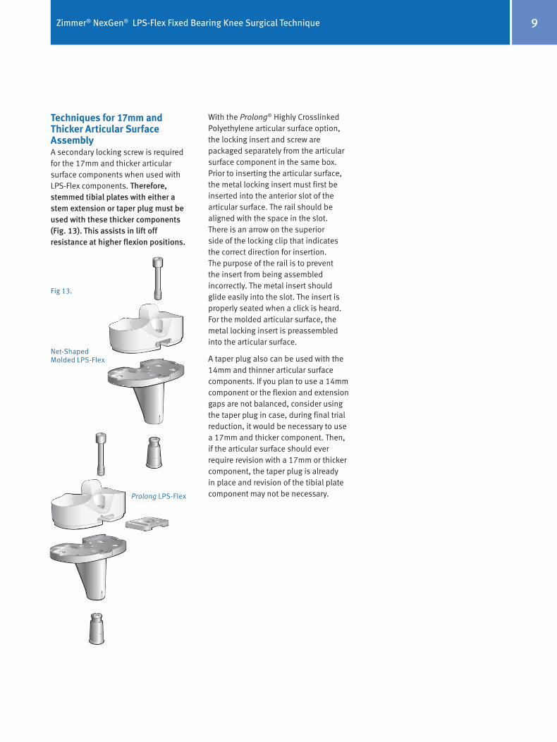
Techniques for 17mm and Thicker Articular Surface AssemblyA secondary locking screw is required for the 17mm and thicker articular surface components when used with LPS-Flex components. Therefore, stemmed tibial plates with either a stem extension or taper plug must be used with these thicker components (Fig. 13). This assists in lift off resistance at higher flexion positions.
Fig 13.
Net-Shaped Molded LPS-Flex
Prolong LPS-Flex
With the Prolong® Highly Crosslinked Polyethylene articular surface option, the locking insert and screw are packaged separately from the articular surface component in the same box. Prior to inserting the articular surface, the metal locking insert must first be inserted into the anterior slot of the articular surface. The rail should be aligned with the space in the slot. There is an arrow on the superior side of the locking clip that indicates the correct direction for insertion. The purpose of the rail is to prevent the insert from being assembled incorrectly. The metal insert should glide easily into the slot. The insert is properly seated when a click is heard. For the molded articular surface, the metal locking insert is preassembled into the articular surface.
A taper plug also can be used with the 14mm and thinner articular surface components. If you plan to use a 14mm component or the flexion and extension gaps are not balanced, consider using the taper plug in case, during final trial reduction, it would be necessary to use a 17mm and thicker component. Then, if the articular surface should ever require revision with a 17mm or thicker component, the taper plug is already in place and revision of the tibial plate component may not be necessary.

10
AssemblyFor Back Table Assembly:1. Assemble the stem extension or the
taper plug onto the tibial plate by striking it with a mallet once for the stem extension or several times for the taper plug to allow the ring on the taper plug to deform.
2. Place the tibial plate on the holding fixture which is an integral part of the instrument case.
3. Use the Articular Surface Inserter to insert the articular surface on the tibial plate.
4. With the articular surface in place, insert the secondary locking screw (packaged with the articular surface).
5. Use the LCCK Deflection Beam Torque Wrench with the 4.5mm Hex Driver Bit attached to torque the screw to 95 in.-lbs. Alternatively, if using a stem extension, use the Tibial Plate Wrench to assist when torquing the screw. Do not over or under torque.
For in vivo Assembly:If preferred, 17mm or thicker articular surface can be inserted after the tibial plate has been implanted.
1. Assemble the stem extension or the taper plug onto the tibial plate by striking it with a mallet once for the stem extension or several times for the taper plug to allow the ring on the taper plug to deform.
It is recommended to secure the taper plug / stem extension using a Replacement Stem Extension Locking Screw: 00-5980-090-00 (available as a separate sterile item) before implanting the tibial component. This screw will hold the taper plug /stem extension in place when the tibial plate is impacted.
2. Implant the tibial plate*. Remove the Replacement Stem Extension Locking Screw and discard. If bone cement is being used, wait for the cement to completely cure before inserting the articular surface. An articular surface provisional may be inserted to use as a spacer while the cement cures.
3. Remove the articular surface provisional and insert the articular surface onto the plate using the Articular Surface Inserter.
4. Select the Tibial Plate Wrench that matches the size of the implant to be assembled. Place the end of the wrench over the tibial plate. Ensure that the wrench is in line with the base of the tibial plate.
5. Place the locking screw (packaged with the articular surface) through the hole in the articular surface.
6. Use the LCCK Deflection Beam Torque Wrench attached to the 4.5mm Hex Driver Bit to torque the screw to 95 in.-lbs.
*For cemented applications, apply a layer of bone cement to the underside of the tibial plate, around the keel, on the resected tibial surface and in the tibial IM canal. Remove the excess cement.

11
Rehabilitation Protocol
An equally important factor in gaining or maintaining high flexion after successful total knee arthroplasty is early and/or aggressive rehabilitation of the patient. Many of the standard rehabilitation protocols used in western-style hospitals today are aimed at restoring knee motion and function between 90˚ and 110˚, which is sufficient for the TKA patient to get into or out of a chair or a car. Those patients undergoing TKA who are able and willing to flex and wish to maintain preoperative flexibility may be better off with early and/or relatively more aggressive rehabilitation exercises.
1. Whiteside LA. Factors affecting range of motion in total knee arthroplasty. J Jpn Orthop Assoc. 1991;65:193-194.
2. Insall JN. Surgery of the Knee. 3rd ed. New York, NY: Churchill Livingston; 2001:1553.
Fig 14.
Fig 15.
ClosureClose the capsule and perform a “drop and dangle” test to predict the range of motion for the patient (Fig. 14).
Position the knee in full extension to continue closing the layers (Fig. 15).

Contact your Zimmer representative or visit us at www.zimmer.com
+H124975964102001/$090521R1G090
97-5964-102-00 Rev.1 0901-K18 5ML Printed in USA ©2004, 2008, 2009 Zimmer, Inc.
Please refer to package insert for complete product information, including contraindications, warnings, precautions, and adverse effects.