
ZigBee RF4CE Specification · 2019-11-15 · ZigBee is not responsible and shall not be held...
106
Copyright 1996-2010 by the ZigBee Alliance. 2400 Camino Ramon, Suite 375, San Ramon, CA 94583, USA http://www.zigbee.org All rights reserved. Permission is granted to members of the ZigBee Alliance to reproduce this document for their own use or the use of other ZigBee Alliance members only, provided this notice is included. All other rights reserved. Duplication for sale, or for commercial or for-profit use is strictly prohibited without the prior written consent of the ZigBee Alliance. ZigBee RF4CE Specification Version 1.01 ZigBee Document 094945r00ZB January, 2010 Sponsored by: ZigBee Alliance Accepted by This document has been accepted for release by the ZigBee Alliance Board of Directors Abstract The ZigBee RF4CE specification describes the protocol infrastructure and services available to applications operating on the ZigBee RF4CE platform Keywords RF4CE, Stack, Network, Application, Discovery, Pairing, Security January, 2010
Transcript of ZigBee RF4CE Specification · 2019-11-15 · ZigBee is not responsible and shall not be held...

Copyright 1996-2010 by the ZigBee Alliance.
2400 Camino Ramon, Suite 375, San Ramon, CA 94583, USA
http://www.zigbee.org
All rights reserved.
Permission is granted to members of the ZigBee Alliance to reproduce this document for their own use or the use of other ZigBee Alliance members only, provided this notice is included. All other rights reserved. Duplication for sale, or for commercial or for-profit use is strictly prohibited without the prior written consent of the ZigBee Alliance.
ZigBee RF4CE Specification
Version 1.01
ZigBee Document 094945r00ZB
January, 2010
Sponsored by: ZigBee Alliance
Accepted by This document has been accepted for release by the ZigBee
Alliance Board of Directors
Abstract The ZigBee RF4CE specification describes the protocol
infrastructure and services available to applications operating
on the ZigBee RF4CE platform
Keywords RF4CE, Stack, Network, Application, Discovery, Pairing,
Security
January, 2010

ZigBee RF4CE Specification ZigBee Document 094945r00ZB, January, 2010
Page ii Copyright 2010, ZigBee Standards Organization. All rights reserved.

ZigBee Document 094945r00ZB, January, 2010 ZigBee RF4CE Specification
Copyright 2010, ZigBee Standards Organization. All rights reserved. Page iii
Notice of use and disclosure The ZigBee Specification is available to individuals, companies and institutions free of charge for all
non-commercial purposes (including university research, technical evaluation, and development of
non-commercial software, tools, or documentation). No part of this specification may be used in
development of a product for sale without becoming a member of ZigBee Alliance.
Copyright © ZigBee Alliance, Inc. (2008). All rights Reserved. This information within this document
is the property of the ZigBee Alliance and its use and disclosure are restricted.
Elements of ZigBee Alliance specifications may be subject to third party intellectual property rights,
including without limitation, patent, copyright or trademark rights (such a third party may or may not
be a member of ZigBee). ZigBee is not responsible and shall not be held responsible in any manner for
identifying or failing to identify any or all such third party intellectual property rights.
This document and the information contained herein are provided on an “AS IS” basis and ZigBee
DISCLAIMS ALL WARRANTIES EXPRESS OR IMPLIED, INCLUDING BUT NOT LIMITED TO
(A) ANY WARRANTY THAT THE USE OF THE INFORMATION HEREIN WILL NOT
INFRINGE ANY RIGHTS OF THIRD PARTIES (INCLUDING WITHOUT LIMITATION ANY
INTELLECTUAL PROPERTY RIGHTS INCLUDING PATENT, COPYRIGHT OR TRADEMARK
RIGHTS) OR (B) ANY IMPLIED WARRANTIES OF MERCHANTABILITY, FITNESS FOR A
PARTICULAR PURPOSE, TITLE OR NONINFRINGEMENT. IN NO EVENT WILL ZIGBEE BE
LIABLE FOR ANY LOSS OF PROFITS, LOSS OF BUSINESS, LOSS OF USE OF DATA,
INTERRUPTION OF BUSINESS, OR FOR ANY OTHER DIRECT, INDIRECT, SPECIAL OR
EXEMPLARY, INCIDENTIAL, PUNITIVE OR CONSEQUENTIAL DAMAGES OF ANY KIND,
IN CONTRACT OR IN TORT, IN CONNECTION WITH THIS DOCUMENT OR THE
INFORMATION CONTAINED HEREIN, EVEN IF ADVISED OF THE POSSIBILITY OF SUCH
LOSS OR DAMAGE. All Company, brand and product names may be trademarks that are the sole
property of their respective owners.
The above notice and this paragraph must be included on all copies of this document that are made.
ZigBee Alliance, Inc.
2400 Camino Ramon, Suite 375
San Ramon, CA 94583

ZigBee RF4CE Specification ZigBee Document 094945r00ZB, January, 2010
Page iv Copyright 2010, ZigBee Standards Organization. All rights reserved.
1

ZigBee Document 094945r00ZB, January, 2010 ZigBee RF4CE Specification
Copyright 2010, ZigBee Standards Organization. All rights reserved. Page v
Table of Contents 1
2
1 Introduction .............................................................................................................................................. 1 3
1.1 Definitions ....................................................................................................................................... 1 4
1.2 Conformance levels ......................................................................................................................... 1 5
1.3 Abbreviations .................................................................................................................................. 1 6
1.4 Conventions..................................................................................................................................... 2 7
1.4.1 Number formats .................................................................................................................. 2 8
1.4.2 Transmission order ............................................................................................................. 2 9
1.4.3 Timing values ..................................................................................................................... 3 10
1.4.4 Message sequence charts .................................................................................................... 3 11
1.4.5 Reserved values .................................................................................................................. 3 12
1.5 References ....................................................................................................................................... 3 13
2 General description .................................................................................................................................. 4 14
2.1 Introduction ..................................................................................................................................... 4 15
2.2 Network topology ............................................................................................................................ 4 16
2.3 Architecture ..................................................................................................................................... 5 17
2.4 The ZigBee RF4CE NWK layer ..................................................................................................... 6 18
2.4.1 2.4GHz band frequencies .................................................................................................... 6 19
2.4.2 Frequency agility ................................................................................................................ 6 20
2.4.3 Node initialisation ............................................................................................................... 7 21
2.4.4 Power saving ....................................................................................................................... 7 22
2.4.5 NWK frames ....................................................................................................................... 7 23
2.4.6 Transmission options .......................................................................................................... 8 24
2.4.7 Discovery ............................................................................................................................ 8 25
2.4.8 Pairing ................................................................................................................................. 8 26
2.4.9 Security ............................................................................................................................... 9 27
2.5 The ZigBee RF4CE application layer ............................................................................................. 9 28
2.6 Concept of primitives ...................................................................................................................... 9 29
3 Network layer specification ................................................................................................................... 11 30
3.1 NWK layer service specification ................................................................................................... 11 31
3.1.1 NWK layer data service .................................................................................................... 11 32
3.1.2 NWK layer management service ...................................................................................... 16 33
3.2 NWK frame formats ...................................................................................................................... 51 34
3.2.1 General NWK frame format ............................................................................................. 51 35
3.2.2 Format of individual frame types ...................................................................................... 53 36
3.3 NWK command frames ................................................................................................................. 55 37
3.3.1 Discovery request command frame .................................................................................. 56 38
3.3.2 Discovery response command frame ................................................................................ 58 39
3.3.3 Pair request command frame ............................................................................................ 60 40
3.3.4 Pair response command frame .......................................................................................... 63 41
3.3.5 Unpair request command frame ........................................................................................ 65 42
3.3.6 Key seed command frame ................................................................................................. 66 43
3.3.7 Ping request command frame ........................................................................................... 67 44
ZigBee RF4CE Specification ZigBee Document 094945r00ZB, January, 2010
Page vi Copyright 2010, ZigBee Standards Organization. All rights reserved.
3.3.8 Ping response command frame ......................................................................................... 68 1
3.4 NWK enumerations, constants and attributes ................................................................................ 69 2
3.4.1 NWK enumerations........................................................................................................... 69 3
3.4.2 NWK constants ................................................................................................................. 70 4
3.4.3 NIB attributes .................................................................................................................... 73 5
3.5 Functional description ................................................................................................................... 76 6
3.5.1 Frequency usage ................................................................................................................ 76 7
3.5.2 LQI mapping ..................................................................................................................... 77 8
3.5.3 Addressing ........................................................................................................................ 77 9
3.5.4 Network topology ............................................................................................................. 77 10
3.5.5 Node initialization ............................................................................................................. 78 11
3.5.6 Use of the MAC beacon payload ...................................................................................... 79 12
3.5.7 Power saving ..................................................................................................................... 80 13
3.5.8 Transmission, reception and acknowledgement ................................................................ 81 14
3.5.9 Discovering services ......................................................................................................... 84 15
3.5.10 Pairing devices .................................................................................................................. 87 16
3.5.11 Security ............................................................................................................................. 90 17
4 Revision History ..................................................................................................................................... 95 18
5 Annex A: Frame security processing example ....................................................................................... 96 19
20

ZigBee Document 094945r00ZB, January, 2010 ZigBee RF4CE Specification
Copyright 2010, ZigBee Standards Organization. All rights reserved. Page vii
1

ZigBee RF4CE Specification ZigBee Document 094945r00ZB, January, 2010
Page viii Copyright 2010, ZigBee Standards Organization. All rights reserved.
List of Figures 1
Figure 1 – Example RC network topology ......................................................................................................5 2
Figure 2 – The ZigBee RF4CE stack architecture ...........................................................................................6 3
Figure 3 – General schematic view of a NWK frame ......................................................................................7 4
Figure 4 – Service primitives ......................................................................................................................... 10 5
Figure 5 – Message sequence chart for the data service ................................................................................ 16 6
Figure 6 – Message sequence chart for auto discovery response ................................................................... 19 7
Figure 7 – Message sequence chart for discovery ......................................................................................... 28 8
Figure 8 – Message sequence chart for pairing ............................................................................................. 39 9
Figure 9 – Message sequence chart for manipulating the receiver ................................................................ 43 10
Figure 10 – Message sequence chart for removing a pairing link ................................................................. 49 11
Figure 11 – General NWK frame format ....................................................................................................... 51 12
Figure 12 – Format of the frame control field ............................................................................................... 52 13
Figure 13 – Data frame format ...................................................................................................................... 53 14
Figure 14 – NWK command frame format .................................................................................................... 55 15
Figure 15 – Format of the discovery request command frame ...................................................................... 56 16
Figure 16 – Format of the vendor information fields..................................................................................... 56 17
Figure 17 – Format of the application information fields .............................................................................. 56 18
Figure 18 – Format of the application capabilities field ................................................................................ 57 19
Figure 19 – Format of the discovery response command frame .................................................................... 59 20
Figure 20 – Format of the pair request command frame ................................................................................ 61 21
Figure 21 – Format of the pair response command frame ............................................................................. 63 22
Figure 22 – Format of the unpair request command frame ............................................................................ 65 23
Figure 23 – Format of the key seed command frame .................................................................................... 66 24
Figure 24 – Format of the ping request command frame ............................................................................... 67 25
Figure 25 – Format of the ping response command frame ............................................................................ 68 26
Figure 26 – Format of the nwkcNodeCapabilities constant ........................................................................... 73 27
Figure 27 – Example ZigBee RF4CE network topology ............................................................................... 78 28
Figure 28 – Format of the MAC beacon payload .......................................................................................... 80 29
Figure 29 – Power saving mechanism concepts ............................................................................................ 80 30
Figure 30 – Target side link key exchange .................................................................................................... 92 31
Figure 31 – Pairing originator side link key exchange .................................................................................. 93 32
33

ZigBee Document 094945r00ZB, January, 2010 ZigBee RF4CE Specification
Copyright 2010, ZigBee Standards Organization. All rights reserved. Page ix
List of Tables 1
Table 1 – NLDE-SAP primitives .................................................................................................................. 11 2
Table 2 – NLDE-DATA.request parameters ................................................................................................. 11 3
Table 3 – NLDE-DATA.indication parameters............................................................................................. 14 4
Table 4 – NLDE-DATA.confirm parameters ................................................................................................ 15 5
Table 5 – NLME-SAP primitives .................................................................................................................. 16 6
Table 6 – NLME-AUTO-DISCOVERY.request parameters ........................................................................ 17 7
Table 7 – NLME-AUTO-DISCOVERY.confirm parameters ....................................................................... 18 8
Table 8 – NLME-COMM-STATUS.indication parameters .......................................................................... 20 9
Table 9 – NLME-DISCOVERY.request parameters ..................................................................................... 21 10
Table 10 – NLME-DISCOVERY.indication parameters .............................................................................. 23 11
Table 11 – NLME-DISCOVERY.response parameters ................................................................................ 25 12
Table 12 – NLME-DISCOVERY.confirm parameters ................................................................................. 26 13
Table 13 – Elements of the NodeDesc type .................................................................................................. 26 14
Table 14 – NLME-GET.request parameters .................................................................................................. 28 15
Table 15 – NLME-GET.confirm parameters ................................................................................................ 29 16
Table 16 – NLME-PAIR.request parameters ................................................................................................ 30 17
Table 17 – NLME-PAIR.indication parameters ............................................................................................ 33 18
Table 18 – NLME-PAIR.response parameters .............................................................................................. 35 19
Table 19 – NLME-PAIR.confirm parameters ............................................................................................... 37 20
Table 20 – NLME-RESET.request parameters ............................................................................................. 39 21
Table 21 – NLME-RESET.confirm parameters ............................................................................................ 40 22
Table 22 – NLME-RX-ENABLE.request parameters ................................................................................... 41 23
Table 23 – NLME-RX-ENABLE.confim parameters ................................................................................... 42 24
Table 24 – NLME-SET.request parameters .................................................................................................. 44 25
Table 25 – NLME-SET.confirm parameters ................................................................................................. 44 26
Table 26 – NLME-START.confirm parameters ............................................................................................ 46 27
Table 27 – NLME-UNPAIR.request parameters........................................................................................... 47 28
Table 28 – NLME-UNPAIR.indication parameters ...................................................................................... 47 29
Table 29 – NLME-UNPAIR.response parameters ........................................................................................ 48 30
Table 30 – NLME-UNPAIR.confirm parameters ......................................................................................... 49 31
Table 31 – NLME-UPDATE-KEY.request parameters ................................................................................ 50 32
Table 32 – NLME-UPDATE-KEY.confirm parameters ............................................................................... 51 33
Table 33 – Values of the frame type sub-field .............................................................................................. 52 34
Table 34 – Values of the channel designator sub-field .................................................................................. 52 35
Table 35 – MCPS-DATA.request parameters for a data frame ..................................................................... 54 36
Table 36 – NWK command frames ............................................................................................................... 56 37
Table 37 – MCPS-DATA.request parameters for a discovery request command frame ............................... 58 38
Table 38 – MCPS-DATA.request parameters for a discovery response command frame ............................ 60 39
Table 39 – MCPS-DATA.request parameters for a pair request command frame ........................................ 62 40
Table 40 – MCPS-DATA.request parameters for a pair response command frame ...................................... 65 41
Table 41 – MCPS-DATA.request parameters for an unpair request command frame .................................. 66 42
Table 42 – MCPS-DATA.request parameters for an key seed command frame ........................................... 67 43
Table 43 – MCPS-DATA.request parameters for a ping request command frame ....................................... 68 44
Table 44 – MCPS-DATA.request parameters for a ping response command frame ..................................... 69 45
Table 45 – NWK enumerations description .................................................................................................. 69 46

ZigBee RF4CE Specification ZigBee Document 094945r00ZB, January, 2010
Page x Copyright 2010, ZigBee Standards Organization. All rights reserved.
Table 46 – NWK layer constants ................................................................................................................... 70 1
Table 47 – The value of the nwkcChannelMask constant .............................................................................. 72 2
Table 48 – NIB attributes .............................................................................................................................. 73 3
Table 49 – Format of a pairing table entry .................................................................................................... 76 4
Table 50 – Initial MAC attribute settings ...................................................................................................... 79 5
Table 51 – Creation of the originator pairing table entry .............................................................................. 88 6
Table 52 – Creation of the recipient pairing table entry ................................................................................ 89 7
8

ZigBee Document 094945r00ZB, January, 2010 ZigBee RF4CE Specification
Copyright 2010, ZigBee Standards Organization. All rights reserved. Page 1
1 Introduction 1
1.1 Definitions 2
Controller A PAN participant that has ZigBee RF4CE functionality.
Destination The device to which an IEEE 802.15.4 transmission is directed.
Device An object that has IEEE 802.15.4 functionality.
Node A device that has ZigBee RF4CE functionality.
Originator The device from which a ZigBee RF4CE transmission is sent.
Pair A logical association between two nodes.
PAN A personal area network as defined in IEEE 802.15.4.
PAN coordinator A device that can create its own PAN.
PAN participant A device that can join a PAN.
RC network Multiple, interoperating, RC PANs.
RC PAN A PAN consisting exclusively of ZigBee RF4CE nodes.
Recipient The device to which a ZigBee RF4CE transmission is directed.
Source The device from which an IEEE 802.15.4 transmission is sent.
Target A PAN coordinator that has ZigBee RF4CE functionality.
3
1.2 Conformance levels 4
The following words, used throughout this document, have specific meanings: 5
May A key word indicating a course of action permissible within the limits of the standard (may
equals is permitted).
Shall A key word indicating mandatory requirements to be strictly followed in order to conform
to the standard; deviations from shall are prohibited (shall equals is required to).
Should A key word indicating that, among several possibilities, one is
recommended as particularly suitable, without mentioning or excluding others; that a
certain course of action is preferred but not necessarily required; or, that (in the negative
form) a certain course of action is deprecated but not prohibited (should equals is
recommended that).
6
1.3 Abbreviations 7
APDU Application protocol data unit
AV Audio visual
CE Consumer electronics
CEC Consumer electronics control
ED Energy detection
EUI Extended unique identifier
DFA Dynamic frequency agility
DLNA Digital living network alliance
FFD Full function device

ZigBee RF4CE Specification ZigBee Document 094945r00ZB, January, 2010
Page 2 Copyright 2010, ZigBee Standards Organization. All rights reserved.
HDMI High definition multimedia interface
ID Identifier
IEEE Institute of electrical and electronic engineers
IR Infrared
LQI Link quality indication
MAC Medium access control
MCPS Medium access control common part sub-layer
MFRC Multi-function remote control
NFR Network layer frame footer
NHR Network layer frame header
NIB Network information base
NLDE Network layer data entity
NLME Network layer management entity
NPDU Network protocol data unit
NSDU Network service data unit
NWK Network
ORG Originator
OSI Open systems interconnection
PAN Personal area network
PHY Physical
POS Personal operating space
RC Remote control
REC Recipient
RF Radio frequency
RF4CE Radio frequency for consumer electronics
SAP Service access point
WPAN Wireless personal area network
1
1.4 Conventions 2
1.4.1 Number formats 3
In this specification hexadecimal numbers are prefixed with the designation “0x” and binary numbers 4
are prefixed with the designation “0b”. All other numbers are assumed to be decimal. 5
1.4.2 Transmission order 6
The frames in this specification are described as a sequence of fields in a specific order. All frame 7
formats are depicted in the order in which they are transmitted by the PHY, from left to right, where the 8
leftmost bit is transmitted first in time. Bits within each field are numbered from 0 (leftmost and least 9
significant) to k-1 (rightmost and most significant), where the length of the field is k bits. Fields that 10
are longer than a single octet are sent to the MAC in the order from the octet containing the lowest 11
numbered bits to the octet containing the highest numbered bits. 12

ZigBee Document 094945r00ZB, January, 2010 ZigBee RF4CE Specification
Copyright 2010, ZigBee Standards Organization. All rights reserved. Page 3
1.4.3 Timing values 1
All timing values within this specification are specified in terms of MAC symbols. One MAC symbol 2
is equal to 16µs. Where appropriate, absolute time values are presented in both MAC symbols and 3
actual time in parenthesis. 4
1.4.4 Message sequence charts 5
During this specification, message sequence charts are used to illustrate the flow of various operations. 6
Instances are labeled with the layer (APL for the application or NWK for the network) followed by the 7
node type (ORG for the originator or REC for the recipient). Primitives are shown in normal style but, 8
for simplicity, without the entity prefix (i.e. NLDE or NLME), e.g. “NLME-PAIR.response” becomes 9
“PAIR.response”. Over the air command frames are labeled in italic text. 10
1.4.5 Reserved values 11
Unless otherwise specified, all reserved fields appearing in a frame structure (c.f. Figure 18) shall be 12
set to zero on transmission and ignored upon reception. Reserved values appearing in multi-value 13
fields (c.f. Table 33) shall not be used. 14
1.5 References 15
[R1] The Institute of Electrical and Electronics Engineers, Inc., IEEE Std. 802.15.4-2006, IEEE 16
Standard for Information Technology. Telecommunications and Information Exchange between 17
Systems. Local and Metropolitan Area Networks. Specific Requirements. Part 15.4: Wireless 18
Medium Access Control (MAC) and Physical Layer (PHY) Specifications for Low Rate 19
Wireless Personal Area Networks (WPANs). New York: IEEE Press. 2006. 20
[R2] ZigBee RF4CE: Vendor ID List, ZigBee Alliance document 094949. 21
[R3] ZigBee RF4CE: Device Type List, ZigBee Alliance document 094950. 22
[R4] ZigBee RF4CE: Profile ID List, ZigBee Alliance document 094951. 23

ZigBee RF4CE Specification ZigBee Document 094945r00ZB, January, 2010
Page 4 Copyright 2010, ZigBee Standards Organization. All rights reserved.
2 General description 1
2.1 Introduction 2
The ZigBee RF4CE standard defines an RC network that provides a simple, robust and low-cost 3
communication network that allows wireless connectivity in applications in the CE domain. The 4
ZigBee RF4CE standard enhances the IEEE 802.15.4 standard by providing a simple networking layer 5
and standard application profiles that can be used to create a multi-vendor interoperable solution for 6
use within the home. 7
Some of the characteristics of an RC network are as follows: 8
Operation in the 2.4GHz frequency band according to IEEE 802.15.4. 9
Frequency agile solution operating over 3 channels. 10
Incorporates power saving mechanisms for all device classes. 11
Service discovery mechanism with full application confirmation. 12
Pairing mechanism with full application confirmation. 13
Multiple star topology with inter-PAN communication. 14
Various transmission options including broadcast. 15
Security key generation mechanism. 16
Utilizes the industry standard AES-128 security scheme. 17
Specifies a simple RC control profile for CE products. 18
Allows standard or vendor-specific profiles to be added. 19
20
2.2 Network topology 21
An RC PAN is composed of two types of device: a target node and a controller node. A target node 22
has full PAN coordinator capabilities and can start a network in its own right. Both types of node can 23
join networks started by target nodes by pairing with that target. Multiple RC PANs form an RC 24
network and nodes in the network can communicate between RC PANs. 25
In order to communicate with a target node, a controller node first switches to the channel and assumes 26
the PAN identifier of the destination RC PAN. It then uses the network address, allocated through the 27
pairing procedure, to identify itself on the RC PAN and thus communicate with the desired target node. 28
Figure 1 illustrates an example ZigBee RF4CE topology which includes three target nodes: a TV, a 29
DVD and a CD player and each target node creates its own RC PAN. The TV, DVD and CD player 30
also have dedicated RCs which are paired to each appropriate target node. A multi-function RC, 31
capable of controlling all three target nodes itself, is added to the network by successively pairing to 32
the desired target nodes. The DVD is also paired with the TV so that an external channel can be 33
selected on the TV when a DVD is played. 34
35

ZigBee Document 094945r00ZB, January, 2010 ZigBee RF4CE Specification
Copyright 2010, ZigBee Standards Organization. All rights reserved. Page 5
TV
DVD
CD
TV RC
DVD RC
CD RC
Multi-function
RC
Target Controller
(PAN 1)
(PAN 2)
(PAN 3)
1
Figure 1 – Example RC network topology 2
3
As a consequence, this RC network consists of three separate RC PANs: one managed by the TV (PAN 4
1), containing the TV RC, the multi-function RC and the DVD; a second managed by the CD player 5
(PAN 2), containing the CD RC and the multi-function RC and a third managed by the DVD (PAN3), 6
containing the DVD RC, multi-function RC and the TV. 7
2.3 Architecture 8
The ZigBee RF4CE architecture is defined in terms of a number of blocks or layers in order to simplify 9
the standard. Each layer is responsible for one part of the standard and offers services to the next 10
higher layer and utilizes services from the next lower layer. The interfaces between the layers serve to 11
define the logical links that are described in this standard. The layout of the layers is based on the open 12
systems interconnection (OSI) seven-layer model. 13
Figure 2 illustrates the ZigBee RF4CE stack architecture. The ZigBee RF4CE protocol is designed to 14
be built onto the IEEE 802.15.4 standard MAC and PHY layers and provides networking functionality 15
and standard application profiles which can interface to the end user application. Manufacturer-16
specific extensions to standard profiles can be defined by sending vendor-specific data frames within a 17
standard profile. In addition, vendor-specific profiles can also be defined. 18
19

ZigBee RF4CE Specification ZigBee Document 094945r00ZB, January, 2010
Page 6 Copyright 2010, ZigBee Standards Organization. All rights reserved.
ZigBee RF4CE Network Layer
Profile 0x01:
CERC
Profile ≥0xc0
Cmd 0x00
Cmd 0x01
…
Cmd 0xff
Vendor
specific
command
set
Profile 0x02
Profile
0x02
command
set
Vendor
specific
command
set
Vendor specific
command set
End User Application
...
ZigBee RF4CE Defined Vendor Specific Application Specific
IEEE 802.15.4
IEEE 802 Defined
1
Figure 2 – The ZigBee RF4CE stack architecture 2
3
2.4 The ZigBee RF4CE NWK layer 4
The NWK layer provides two services: the NWK layer data service, interfacing to the NWK layer data 5
entity (NLDE) and the NWK layer management service, interfacing to the NWK layer management 6
entity (NLME). These services are accessed through the NWK layer data entity SAP (NLDE-SAP) 7
and the NWK layer management entity SAP (NLME-SAP). 8
The NWK layer data service enables the transmission and reception of NWK protocol data units 9
(NPDUs) across the MAC data service. The NWK layer management service permits service 10
discovery, pairing, unpairing, receiver control, node initialisation and NIB attribute manipulation. 11
2.4.1 2.4GHz band frequencies 12
A ZigBee RF4CE node operates in the 2.4GHz frequency band, as specified by IEEE 802.15.4. 13
However, in an attempt to be robust against other common sources of interference in this band, only a 14
small subset of channels is used - namely channels 15, 20 and 25. A target node can choose to start its 15
network on the best available channel at startup time and so an RC network may operate over one or 16
more of the available three channels. 17
2.4.2 Frequency agi l ity 18
All ZigBee RF4CE nodes support frequency agility across all three permitted channels. As described 19
above, a target node selects its own initial channel, based on the channel conditions during startup. 20
During the course of the life of the target node, however, the channel conditions may vary to such an 21
extent that the channel becomes compromised and communication becomes problematic. If this 22
happens, the target node can elect to switch to another channel that may provide a better level of 23
service. 24
Each node paired to the target records the channel on which communication is expected. However, in 25
the event that the target switches to another channel, the node can attempt transmission on the other 26
channels until communication with the target is reacquired. The node can then record the new channel 27
accordingly for the next time communication is attempted. 28

ZigBee Document 094945r00ZB, January, 2010 ZigBee RF4CE Specification
Copyright 2010, ZigBee Standards Organization. All rights reserved. Page 7
2.4.3 Node init ial isat ion 1
A ZigBee RF4CE node initialises itself according to whether it is a target or a controller. Controller 2
nodes simply configure the stack according to this standard and start operating normally. Target nodes 3
configure the stack as controller nodes do but then attempt to start a network. 4
To do this, the target node first performs an energy detection scan which allows it to obtain information 5
on the usage of each available channel, thus allowing it to select a suitable channel on which to operate. 6
The target node then performs an active scan which allows it to determine the identifiers of any other 7
IEEE 802.15.4 PANs (ZigBee RF4CE or otherwise) operating on the selected channel, thus allowing a 8
unique PAN identifier to be selected for its network. The target node then begins operating normally. 9
2.4.4 Power saving 10
Power saving is an important consideration for a ZigBee RF4CE node. As a consequence, this 11
standard defines a power save mechanism that allows both controller nodes as well as target nodes to 12
manage their power consumption by entering a power saving mode. The power saving mechanism is 13
under the control of each application. 14
A node can manipulate its receiver in a number of ways: 15
The receiver can be enabled until further notice (e.g. when a TV comes out of standby). 16
The receiver can be enabled for a finite period (e.g. when a TV enters standby mode and 17
wants to engage the power saving mode). 18
The receiver can be disabled until further notice (e.g. when an RC enters a dormant state due 19
to none of its buttons being pressed). 20
21
When the power saving mode is engaged, the receiver is enabled for an application defined duration 22
(known as the active period) and then disabled. This mechanism is then repeated at an application 23
defined interval (known as the duty cycle). Other nodes can still communicate with a node in power 24
saving mode by targeting the transmission during the active period. The result is a node that 25
periodically enables its receiver for only a short time, hence allowing it to conserve power but still be 26
able to be active on the network. 27
2.4.5 NWK frames 28
The ZigBee RF4CE NWK layer defines three frame types: standard data, network command and 29
vendor-specific data. Standard data frames transport application data from standard application 30
profiles. Network command frames transport frames which allow the network layer to accomplish 31
certain tasks such as discovery or pairing. Vendor-specific data frames transport vendor-specific 32
application data. 33
The general NWK frame format is illustrated in Figure 3. 34
35
Octets: 1 4 0/1 0/2 Variable 0/4
Frame control Frame counter Profile
identifier
Vendor
identifier Frame payload
Message
integrity code
Header Payload Footer
Figure 3 – General schematic view of a NWK frame 36
37
The fields of the general NWK frame are described below: 38
Frame control: control information for the frame 39
Frame counter: incrementing counter to detect duplicates and prevent replay attacks (security) 40
Profile identifier: the application frame format being transported 41
Vendor identifier: to allow vendor extensions 42
Frame payload: contains the application frame 43
Message integrity code: to provide authentication (security) 44

ZigBee RF4CE Specification ZigBee Document 094945r00ZB, January, 2010
Page 8 Copyright 2010, ZigBee Standards Organization. All rights reserved.
1
2.4.6 Transmission options 2
The ZigBee RF4CE protocol defines a number of transmission options that can be used by an 3
application and combined as appropriate: 4
Acknowledged: Originator data is confirmed by the recipient 5
Unacknowledged: Originator data is not confirmed by the recipient 6
Unicast: Originator data is sent to a specific recipient 7
Broadcast: Originator data is sent to all recipients 8
Multiple channel: Originator attempts transmission using frequency re-acquisition mechanism 9
Single channel: Originator attempts transmission on the expected channel 10
11
2.4.7 Discovery 12
A ZigBee RF4CE node can perform service discovery in an attempt to find other suitable nodes that 13
can be paired to. Discovery can be attempted repeatedly on all three channels for a fixed duration or 14
until a sufficient number of responses have been received. Service discovery is only available to nodes 15
that are not currently in power saving mode. 16
During discovery, a number of pieces of information are exchanged between both devices. This 17
information is passed to the application which can then make a decision whether it should respond. 18
The information exchanged is as follows: 19
Node capabilities: The type of the node (i.e. target or controller), whether the node is mains or 20
battery powered and whether it supports security. 21
Vendor information: The ZigBee RF4CE SIG allocated vendor identifier and a freeform 22
vendor string specifying vendor-specific identification (e.g. a serial number). 23
Application information: A short user defined string which describes the application 24
functionality of the node (e.g. “lounge TV”), a device type list specifying which types of 25
device are supported (e.g. a combo device may support both “TV” and “DVD” functionality) 26
and a profile identifier list specifying which application profiles are supported by the node 27
(e.g. the CERC profile or a vendor-specific profile). 28
Requested device type: The type of device being requested through the discovery (e.g. a 29
multifunction remote control may be searching for “TV” functionality). 30
31
2.4.8 Pairing 32
Once a node has determined, through discovery, that there is another node within communication range 33
offering compatible services, it can set up a pairing link in order to begin communication. Nodes 34
within an RC network may only communicate directly with other nodes on the network if a pairing link 35
exists between the originator and the recipient nodes. 36
A pairing link can be established on request from the application by exchanging a similar set of 37
information as was exchanged during discovery. The application on the target node can choose 38
whether to accept the pair (e.g. only if it has capacity to store the pairing link) and confirms the pairing 39
request back to the originator node. 40
If the pairing request was successful, both nodes store a pairing link in their respective pairing tables. 41
This allows an originator to communicate with a target and the target to communicate back to the 42
originator. Each entry in the pairing table contains all the information necessary for the network layer 43
to transmit a frame to the target node. This removes the burden of addressing, etc. from the application 44
layer which can simply supply an index into the pairing table in order to communicate with another 45
device. 46
Each entry in the pairing table contains the following information: 47
Pairing reference 48
Source network address 49

ZigBee Document 094945r00ZB, January, 2010 ZigBee RF4CE Specification
Copyright 2010, ZigBee Standards Organization. All rights reserved. Page 9
Destination logical channel 1
Destination IEEE address 2
Destination PAN identifier 3
Destination network address 4
Recipient node capabilities 5
Recipient frame counter 6
Security link key 7
8
2.4.9 Security 9
Like any other wireless network, an RC network could be vulnerable to both passive eavesdropping 10
and unauthorised tampering of the messages being transferred between nodes. To solve this, the 11
ZigBee RF4CE standard provides a cryptographic mechanism to protect the transmissions. This 12
mechanism provides the following security services: 13
Data confidentiality: To ensure that the data contained in a ZigBee RF4CE transmission can 14
only be disclosed to the intended recipient. 15
Data authenticity: To ensure that the intended recipient of a ZigBee RF4CE transmission 16
knows that the data was sent from a trusted source and not modified during transmission. 17
Replay protection: To ensure that a secure transmission cannot simply be repeated by an 18
attacking device if overheard. 19
20
A 128-bit cryptographic key is generated by the recipient of the pairing request and exchanged with the 21
originator. The key is stored in the respective pairing tables. 22
2.5 The ZigBee RF4CE application layer 23
The application layer of a ZigBee RF4CE node is composed of a profile component and an application-24
specific component. The profile component can be thought of as a common language that nodes 25
implementing the profile exchange to accomplish certain tasks, e.g. switching the channel on a TV. 26
The application component is provided by the end manufacturer in order to add specific functionality to 27
the commands requested through the profile. 28
The ZigBee RF4CE standard defines standard profiles (e.g. CERC) but also permits vendors to either 29
extend standard profiles or to define completely proprietary profiles. 30
The Consumer Electronics Remote Control (CERC) profile is once such standard profile defined by the 31
ZigBee RF4CE SIG. This profile defines commands and procedures to enable CE devices (e.g. a TV, 32
DVD or CD player) to be controlled by remote control devices. 33
2.6 Concept of primitives 34
This clause provides a brief overview of the concept of service primitives. Please refer to IEEE Std 35
802.2 1998 edition for more detailed information. 36
The services of a layer are the capabilities it offers to the user in the next higher layer or sub-layer by 37
building its functions on the services of the next lower layer. This concept is illustrated in Figure 4 38
where the service hierarchy and the relationship of the two correspondent N-users and their associated 39
N-layer (or sub-layer) peer protocol entities. 40
41

ZigBee RF4CE Specification ZigBee Document 094945r00ZB, January, 2010
Page 10 Copyright 2010, ZigBee Standards Organization. All rights reserved.
Service Provider
(N-Layer)
N-Layer
Service User
(N+1 Layer)
N-Layer
Service User
(N+1 Layer)
Request
Confirm
Indication
Response
1
Figure 4 – Service primitives 2
3
The services are specified by describing the information flow between the N-user and the N-layer. This 4
information flow is modeled by discrete, instantaneous events, which characterize the provision of a 5
service. Each event consists of passing a service primitive from one layer to the other through a layer 6
service access point associated with an N-user. Service primitives convey the required information by 7
providing a particular service. These service primitives are an abstraction since they only specify the 8
provided service rather than the means by which it is provided. This definition is independent of any 9
other interface implementation. 10
Services are specified by describing the service primitives and parameters that characterize it. A service 11
may have one or more related primitives that constitute the activity that is related to that particular 12
service. Each service primitive may have zero or more parameters that convey the information required 13
to provide the service. 14
A primitive can be one of four generic types: 15
Request: The request primitive is passed from the N-user to the N-layer to request that a ser-16
vice is initiated. 17
Indication: The indication primitive is passed from the N-layer to the N-user to indicate an 18
internal N-layer event that is significant to the N-user. This event may be logically related to a 19
remote service request, or it may be caused by an N-layer internal event. 20
Response: The response primitive is passed from the N-user to the N-layer to complete a pro-21
cedure previously invoked by an indication primitive. 22
Confirm: The confirm primitive is passed from the N-layer to the N-user to convey the results 23
of one or more associated previous service requests. 24
25

ZigBee Document 094945r00ZB, January, 2010 ZigBee RF4CE Specification
Copyright 2010, ZigBee Standards Organization. All rights reserved. Page 11
3 Network layer specification 1
3.1 NWK layer service specification 2
3.1.1 NWK layer data service 3
The NLDE-SAP supports the transport of application protocol data units (APDUs) between peer 4
application entities. Table 1 lists the primitives supported by the NLDE-SAP. These primitives are 5
discussed in the sub-clauses referenced in the table. 6
7
Table 1 – NLDE-SAP primitives 8
Name Request Indication Confirm
NLDE-DATA 3.1.1.1 3.1.1.2 3.1.1.3
9
3.1.1.1 NLDE-DATA.request 10
The NLDE-DATA.request primitive requests the transfer of a data APDU (i.e. NSDU) from a local 11
application entity to a peer application entity. 12
3.1.1.1.1 Semantics of the service primitive 13
The semantics of the NLDE-DATA.request primitive are as follows: 14
15
NLDE-DATA.request (
PairingRef,
ProfileId,
VendorId,
nsduLength,
nsdu,
TxOptions
)
16
Table 2 specifies the parameters for the NLDE-DATA.request primitive. 17
18
Table 2 – NLDE-DATA.request parameters 19
Name Type Valid range Description
PairingRef Integer 0x00 – 0xfe Reference into the pairing table which
contains the information required to
transmit the NSDU.
This parameter is ignored if the
TxOptions parameter specifies a
broadcast transmission.
ProfileId Integer 0x00 – 0xff The identifier of the profile indicating the
format of the transmitted data.

ZigBee RF4CE Specification ZigBee Document 094945r00ZB, January, 2010
Page 12 Copyright 2010, ZigBee Standards Organization. All rights reserved.
Name Type Valid range Description
VendorId Vendor
identifier
0x0000 or a valid vendor
identifier
If the TxOptions parameter specifies that
the data is vendor-specific, this
parameter specifies the vendor identifier.
If this parameter is equal to 0x0000, the
vendor identifier should be set to
nwkcVendorIdentifier.
If the TxOptions parameter specifies that
the data is not vendor-specific this
parameter is ignored.
nsduLength Integer 0 – (aMaxMACSafe-
PayloadSize –
nwkcMinNWKHeader-
Overhead)
(See [R1])
The number of octets contained in the
NSDU to be transmitted by the NLDE.
nsdu Set of
octets
- The set of octets forming the NSDU to
be transmitted by the NLDE.
TxOptions Bitmap 7-bit field Transmission options for this NSDU.
For bB0B (transmission mode):
1 = broadcast transmission
0 = unicast transmission
For bB1B (destination addressing mode):
1 = use destination IEEE address
0 = use destination network address
For bB2 B(acknowledgement mode):
1 = acknowledged transmission
0 = unacknowledged transmission
For bB3B (security mode):
1 = transmit with security
0 = transmit without security
For bB4B (channel agility mode):
1 = use single channel operation
0 = use multiple channel operation
For bB5B (channel normalization mode):
1 = specify channel designator
0 = do not specify channel designator
For bB6B (payload mode):
1 = data is vendor-specific
0 = data is not vendor-specific
3.1.1.1.2 When generated 1
The NLDE-DATA.request primitive is generated by a local application entity when a data APDU (i.e. 2
NSDU) is to be transferred to a peer application entity. 3
3.1.1.1.3 Effect on receipt 4
On receipt of the NLDE-DATA.request primitive, the NLDE begins the transmission of the supplied 5
NSDU. 6
If nwkFrameCounter is equal to its maximum value (0xffffffff), the NLDE will issue the NLDE-7
DATA.confirm primitive with a status of FRAME_COUNTER_EXPIRED and perform no further 8
processing. 9
ZigBee Document 094945r00ZB, January, 2010 ZigBee RF4CE Specification
Copyright 2010, ZigBee Standards Organization. All rights reserved. Page 13
The NLDE builds an NPDU to transmit from the supplied arguments and the supplied NSDU will be 1
placed in the NWK frame payload. 2
If the transmission mode flag of the TxOptions parameter indicates that a broadcast transmission is 3
required, the NLDE transmits the NPDU with a destination PAN identifier and destination address of 4
0xffff. If the originator is a target, the source address is set to the network address of the originator. 5
Otherwise, the source address is set to the IEEE address of the originator. In addition, the transmission 6
will always be sent unacknowledged and with security disabled. In this case, the destination addressing 7
mode and acknowledgement mode flags are ignored. 8
If the transmission mode flag of the TxOptions parameter indicates that a unicast transmission is 9
required, the NLDE uses the PairingRef parameter to determine the recipient information with which to 10
transmit the NPDU. If no entry exists in the pairing table with this reference, the NLDE will issue the 11
NLDE-DATA.confirm primitive with a status of NO_PAIRING and the NPDU will not be transmitted. 12
If an entry exists in the pairing table with this reference, the NLDE uses the corresponding channel and 13
addressing information contained in the pairing table entry to instruct the MAC sub-layer to transmit 14
the frame. If the destination addressing mode flag of the TxOptions parameter indicates that a 15
destination IEEE address is required or the recipient is a controller, the NLDE uses the destination 16
IEEE address field of the pairing table entry. Otherwise, the NLDE uses the destination network 17
address field in the pairing table entry. If the acknowledgement mode flag of the TxOptions parameter 18
indicates that an acknowledgement is required, the NLDE instructs the MAC sub-layer to transmit the 19
frame with an acknowledgement request. Otherwise, the NLDE instructs the MAC sub-layer to 20
transmit the frame without an acknowledgement request. 21
If the security mode flag of the TxOptions parameter indicates that security is required for this 22
transmission, the NLDE uses the PairingRef parameter to determine whether a secure link is available 23
to the recipient. If a secure link to the recipient is not available, the NLDE will issue the NLDE-24
DATA.confirm primitive with a status of INVALID_PARAMETER and the NPDU will not be 25
transmitted. If a secure link to the recipient is available, the NLDE secures the frame using the 26
procedures described in 3.5.11.3 before transmitting the frame. 27
If the security mode flag of the TxOptions parameter indicates that security is not required for this 28
transmission, the NLDE transmits the frame without security. 29
If the channel agility mode flag of the TxOptions parameter indicates that single channel operation is 30
required, the NLDE attempts to transmit the frame only on the current channel (as specified in the 31
corresponding entry of the pairing table). Otherwise, the NLDE attempts to transmit the frame on 32
multiple channels, according to the frequency agility mechanism. 33
If the channel normalization mode flag of the TxOptions parameter indicates that a channel designator 34
be specified, the NLDE sets the channel designator sub-field of the frame control field according to the 35
value of nwkBaseChannel. Otherwise, the NLDE sets the channel designator sub-field of the frame 36
control field to zero. 37
If the payload mode flag of the TxOptions parameter indicates that the data is vendor-specific, the 38
NLDE sets the frame type sub-field of the frame control field to indicate a vendor-specific data frame. 39
Otherwise, the NLDE sets the frame type sub-field of the frame control field to indicate a standard data 40
frame. 41
The NWK layer transmits the NPDU according to the transmission procedures defined in sub-clause 42
3.5.8 and via the MCPS-DATA.request primitive. 43
Once the NLDE receives the MCPS-DATA.confirm from the MAC sub-layer, it will issue the NLDE-44
DATA.confirm primitive along with the original pairing reference and the status value from the MCPS-45
DATA.confirm. 46
If any parameter in the NLDE-DATA.request primitive is not supported or is out of range, the NLDE 47
will issue the NLDE-DATA.confirm primitive with a status of INVALID_PARAMETER. 48
49
3.1.1.2 NLDE-DATA.indicat ion 50
3.1.1.2.1 Semantics of the service primitive 51
The semantics of the NLDE-DATA.indication primitive are as follows: 52
53

ZigBee RF4CE Specification ZigBee Document 094945r00ZB, January, 2010
Page 14 Copyright 2010, ZigBee Standards Organization. All rights reserved.
NLDE-DATA.indication (
PairingRef,
ProfileId,
VendorId,
nsduLength,
nsdu,
RxLinkQuality,
RxFlags
)
1
Table 3 specifies the parameters for the NLDE-DATA.indication primitive. 2
3
Table 3 – NLDE-DATA.indication parameters 4
Name Type Valid range Description
PairingRef Integer 0x00 – 0xfe Reference into the pairing table which
matched the information contained in the
received NPDU.
ProfileId Integer 0x00 – 0xff The identifier of the profile indicating the
format of the received data.
VendorId Vendor
identifier
A valid vendor
identifier
If the RxFlags parameter specifies that the
data is vendor-specific, this parameter
specifies the vendor identifier. If the
RxFlags parameter specifies that the data is
not vendor-specific this parameter is
ignored.
nsduLength Integer 0 – (aMaxMACSafe-
PayloadSize –
nwkcMinNWKHeader-
Overhead)
The number of octets contained in the
NSDU received by the NLDE.
nsdu Set of
octets
- The set of octets forming the NSDU
received by the NLDE.
RxLinkQuality Integer 0x00 – 0xff LQI value measured during the reception
of the NPDU. Lower values represent
lower LQI.
RxFlags Bitmap 3-bit field Reception indication flags for this NSDU.
For bB0 B (reception mode):
1 = received as broadcast
0 = received as unicast
For bB1 B (security mode):
1 = received with security
0 = received without security
For bB2 B (payload mode):
1 = data is vendor-specific
0 = data is not vendor-specific
5

ZigBee Document 094945r00ZB, January, 2010 ZigBee RF4CE Specification
Copyright 2010, ZigBee Standards Organization. All rights reserved. Page 15
3.1.1.2.2 When generated 1
The NLDE-DATA.indication primitive is generated by the NLDE and issued to the application on 2
receipt of a data frame at the local NWK layer entity. 3
3.1.1.2.3 Effect on receipt 4
On receipt of the NLDE-DATA.indication primitive, the application is notified of the arrival of data at 5
the device. The RxLinkQuality parameter contains the LQI value reported via the MAC sub-layer of 6
the received frame. 7
The reception mode flag of the RxFlags parameter indicates whether the frame was received as a 8
broadcast or as a unicast. 9
The security mode flag of the RxFlags parameter indicates whether the frame was secured. 10
If the payload mode flag of the RxFlags parameter indicates that the frame is vendor-specific, the 11
VendorId parameter will contain the vendor identifier to use to decode the payload. Otherwise, the 12
VendorId parameter should be ignored. 13
14
3.1.1.3 NLDE-DATA.confirm 15
3.1.1.3.1 Semantics of the service primitive 16
The semantics of the NLDE-DATA.confirm primitive are as follows: 17
18
NLDE-DATA.confirm (
Status,
PairingRef
)
19
Table 4 specifies the parameters for the NLDE-DATA.confirm primitive. 20
21
Table 4 – NLDE-DATA.confirm parameters 22
Name Type Valid range Description
Status Enumeration SUCCESS,
INVALID_PARAMETER,
NO_PAIRING,
NO_RESPONSE,
FRAME_COUNTER_EXPIRED
or any status value from the
MCPS-DATA.confirm.
The status of the NSDU
transmission.
PairingRef Integer 0x00 – 0xfe The pairing table reference for
the NSDU being confirmed.
23
3.1.1.3.2 When generated 24
The NLDE-DATA.confirm primitive is generated by the NWK layer entity in response to an NLDE-25
DATA.request primitive. The NLDE-DATA.confirm primitive returns a status of either SUCCESS, 26
indicating that the request to transmit was successful, or the appropriate error code. The status values 27
are fully described in 3.1.1.1.3. 28

ZigBee RF4CE Specification ZigBee Document 094945r00ZB, January, 2010
Page 16 Copyright 2010, ZigBee Standards Organization. All rights reserved.
3.1.1.3.3 Effect on receipt 1
On receipt of the NLDE-DATA.confirm primitive, the application of the originator node is notified of 2
the result of its request to transmit. If the transmission attempt was successful, the status parameter 3
will be set to SUCCESS. Otherwise, the status parameter will indicate the error. 4
3.1.1.3.4 Data service message sequence char t 5
Figure 5 illustrates the sequence of messages necessary for a successful data transfer between two 6
nodes. 7
8
APL-ORG NWK-ORG NWK-REC APL-REC
Data frame
DATA.indication
DATA.request
DATA.confirm
9 10
Figure 5 – Message sequence chart for the data service 11
12
3.1.2 NWK layer management service 13
The NLME-SAP allows the transport of management commands between the application and the 14
NLME. Table 5 summarizes the primitives supported by the NLME through the NLME-SAP interface. 15
The primitives are discussed in the sub-clauses referenced in the table. 16
17
Table 5 – NLME-SAP primitives 18
Name Request Indication Response Confirm
NLME-AUTO-DISCOVERY 3.1.2.1 3.1.2.2
NLME-COMM-STATUS 3.1.2.3
NLME-DISCOVERY 3.1.2.4 3.1.2.5 3.1.2.6 3.1.2.7
NLME-GET 3.1.2.8 3.1.2.9
NLME-PAIR 3.1.2.10 3.1.2.11 3.1.2.12 3.1.2.13
NLME-RESET 3.1.2.14 3.1.2.15
NLME-RX-ENABLE 3.1.2.16 3.1.2.17
NLME-SET 3.1.2.18 3.1.2.19
NLME-START 3.1.2.20 3.1.2.21
NLME-UNPAIR 3.1.2.22 3.1.2.23 3.1.2.24 3.1.2.25
NLME-UPDATE-KEY 3.1.2.26 3.1.2.27
19

ZigBee Document 094945r00ZB, January, 2010 ZigBee RF4CE Specification
Copyright 2010, ZigBee Standards Organization. All rights reserved. Page 17
3.1.2.1 NLME-AUTO-DISCOVERY.request 1
The NLME-AUTO-DISCOVERY.request primitive allows the application to request the NLME 2
automatically handles the receipt of discovery request command frames. Note that during this auto 3
discovery response mode, the NLME does not inform the application of the arrival of discovery request 4
command frames via the NLME-DISCOVERY.indication primitive. 5
3.1.2.1.1 Semantics of the service primitive 6
The semantics of the NLME-AUTO-DISCOVERY.request primitive are as follows: 7
8
NLME-AUTO-DISCOVERY.request (
RecAppCapabilities,
RecDevTypeList,
RecProfileIdList,
AutoDiscDuration
)
9
Table 6 specifies the parameters for the NLME-AUTO-DISCOVERY.request primitive. 10
11
Table 6 – NLME-AUTO-DISCOVERY.request parameters 12
Name Type Valid range Description
RecAppCapabilities Bitmap See Figure 18 The application capabilities of the node
issuing this primitive.
RecDevTypeList List of
integers
Each integer:
0x00 – 0xfe
The list of device types supported by the
node issuing this primitive.
The set of supported device types is
specified in [R3] .
RecProfileIdList List of
integers
Each integer:
0x00 – 0xff
The list of profile identifiers supported by
the node issuing this primitive.
The set of supported profile identifiers is
specified in [R4]
AutoDiscDuration Integer 0x000000 –
0xffffff
The maximum number of MAC symbols
NLME will be in auto discovery response
mode.
13
3.1.2.1.2 When generated 14
The NLME-AUTO-DISCOVERY.request primitive is generated by the local application entity and 15
issued to the NLME to request automatic discovery response mode. In this mode, the NLME 16
determines whether to respond to received discovery request command frames according to the 17
information contained in this primitive. 18
3.1.2.1.3 Effect on receipt 19
On receipt of this primitive, the NLME enters auto discovery response mode for at most the time 20
specified in the AutoDiscDuration parameter. During this mode, if the node receives a command frame 21
that is not a discovery request command frame it will be discarded. 22
On receipt of a discovery request command frame, the NLME checks that the requested device type 23
field matches one of the device types listed in the RecDevTypeList parameter and that at least one of 24
the profile identifiers listed in the profile identifier list field matches one of the profile identifiers listed 25
in the RecProfileIdList parameter. If a match is found, the NLME waits for the reception of a second 26
ZigBee RF4CE Specification ZigBee Document 094945r00ZB, January, 2010
Page 18 Copyright 2010, ZigBee Standards Organization. All rights reserved.
identical discovery request command frame to be received from the same node and again checks for a 1
match. 2
If the second discovery request command frame matches, the NLME generates a discovery response 3
command frame (see 3.3.2). The NLME transmits the frame on its current channel by issuing the 4
MCPS-DATA.request primitive to the MAC sub-layer. 5
On receipt of an MCPS-DATA.confirm primitive from the MAC sub-layer, the NLME issues the 6
NLME-AUTO-DISCOVERY.confirm primitive with the status value contained in the primitive. 7
If a second discovery request command frame is received from a different node, the NLME issues the 8
NLME-AUTO-DISCOVERY.confirm primitive with the status of DISCOVERY_ERROR. 9
If a discovery request command frame is received that does not match the information contained in this 10
primitive, the NLME discards the frame and remains in auto discovery mode. 11
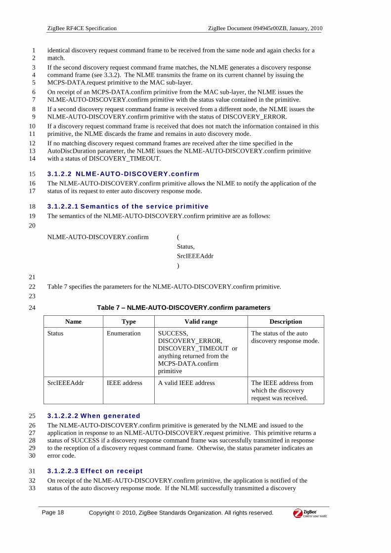
If no matching discovery request command frames are received after the time specified in the 12
AutoDiscDuration parameter, the NLME issues the NLME-AUTO-DISCOVERY.confirm primitive 13
with a status of DISCOVERY_TIMEOUT. 14
3.1.2.2 NLME-AUTO-DISCOVERY.conf irm 15
The NLME-AUTO-DISCOVERY.confirm primitive allows the NLME to notify the application of the 16
status of its request to enter auto discovery response mode. 17
3.1.2.2.1 Semantics of the service primitive 18
The semantics of the NLME-AUTO-DISCOVERY.confirm primitive are as follows: 19
20
NLME-AUTO-DISCOVERY.confirm (
Status,
SrcIEEEAddr
)
21
Table 7 specifies the parameters for the NLME-AUTO-DISCOVERY.confirm primitive. 22
23
Table 7 – NLME-AUTO-DISCOVERY.confirm parameters 24
Name Type Valid range Description
Status Enumeration SUCCESS,
DISCOVERY_ERROR,
DISCOVERY_TIMEOUT or
anything returned from the
MCPS-DATA.confirm
primitive
The status of the auto
discovery response mode.
SrcIEEEAddr IEEE address A valid IEEE address The IEEE address from
which the discovery
request was received.
3.1.2.2.2 When generated 25
The NLME-AUTO-DISCOVERY.confirm primitive is generated by the NLME and issued to the 26
application in response to an NLME-AUTO-DISCOVERY.request primitive. This primitive returns a 27
status of SUCCESS if a discovery response command frame was successfully transmitted in response 28
to the reception of a discovery request command frame. Otherwise, the status parameter indicates an 29
error code. 30
3.1.2.2.3 Effect on receipt 31
On receipt of the NLME-AUTO-DISCOVERY.confirm primitive, the application is notified of the 32
status of the auto discovery response mode. If the NLME successfully transmitted a discovery 33

ZigBee Document 094945r00ZB, January, 2010 ZigBee RF4CE Specification
Copyright 2010, ZigBee Standards Organization. All rights reserved. Page 19
response command frame in response to the reception of a discovery request command frame, the 1
status parameter will indicate a successful auto discovery response and the SrcIEEEAddr parameter 2
will contain the IEEE address of the node to which it was sent. Otherwise, the status parameter 3
indicates an error code and the SrcIEEEAddr parameter should be ignored. 4
3.1.2.2.4 Auto discovery response message sequence chart 5
Figure 6 illustrates the sequence of messages necessary for a successful automatic discovery response 6
mechanism. 7
8
ORG NWK-REC APL-REC
Discovery Request
AUTO-DISCOVERY.request
Discovery Response
AutoDiscDuration
AUTO-DISCOVERY.confirm
Discovery Request
Rx 1
Rx 2
9
Figure 6 – Message sequence chart for auto discovery response 10
3.1.2.3 NLME-COMM-STATUS.indicat ion 11
The NLME-COMM-STATUS.indication primitive allows the NLME to notify the application of a 12
communication status. 13
3.1.2.3.1 Semantics of the service primitive 14
The semantics of the NLME-COMM-STATUS.indication primitive are as follows: 15
16
NLME-COMM-STATUS.indication (
Status,
PairingRef,
DstPANId,
DstAddrMode,
DstAddr)
17
Table 6 specifies the parameters for the NLME-COMM-STATUS.indication primitive. 18
19
ZigBee RF4CE Specification ZigBee Document 094945r00ZB, January, 2010
Page 20 Copyright 2010, ZigBee Standards Organization. All rights reserved.
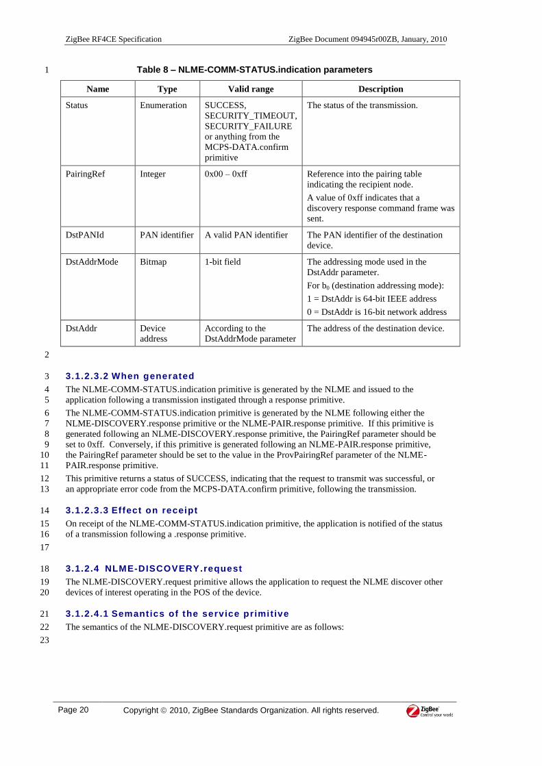
Table 8 – NLME-COMM-STATUS.indication parameters 1
Name Type Valid range Description
Status Enumeration SUCCESS,
SECURITY_TIMEOUT,
SECURITY_FAILURE
or anything from the
MCPS-DATA.confirm
primitive
The status of the transmission.
PairingRef Integer 0x00 – 0xff Reference into the pairing table
indicating the recipient node.
A value of 0xff indicates that a
discovery response command frame was
sent.
DstPANId PAN identifier A valid PAN identifier The PAN identifier of the destination
device.
DstAddrMode Bitmap 1-bit field The addressing mode used in the
DstAddr parameter.
For bB0 B (destination addressing mode):
1 = DstAddr is 64-bit IEEE address
0 = DstAddr is 16-bit network address
DstAddr Device
address
According to the
DstAddrMode parameter
The address of the destination device.
2
3.1.2.3.2 When generated 3
The NLME-COMM-STATUS.indication primitive is generated by the NLME and issued to the 4
application following a transmission instigated through a response primitive. 5
The NLME-COMM-STATUS.indication primitive is generated by the NLME following either the 6
NLME-DISCOVERY.response primitive or the NLME-PAIR.response primitive. If this primitive is 7
generated following an NLME-DISCOVERY.response primitive, the PairingRef parameter should be 8
set to 0xff. Conversely, if this primitive is generated following an NLME-PAIR.response primitive, 9
the PairingRef parameter should be set to the value in the ProvPairingRef parameter of the NLME-10
PAIR.response primitive. 11
This primitive returns a status of SUCCESS, indicating that the request to transmit was successful, or 12
an appropriate error code from the MCPS-DATA.confirm primitive, following the transmission. 13
3.1.2.3.3 Effect on receipt 14
On receipt of the NLME-COMM-STATUS.indication primitive, the application is notified of the status 15
of a transmission following a .response primitive. 16
17
3.1.2.4 NLME-DISCOVERY.request 18
The NLME-DISCOVERY.request primitive allows the application to request the NLME discover other 19
devices of interest operating in the POS of the device. 20
3.1.2.4.1 Semantics of the service primitive 21
The semantics of the NLME-DISCOVERY.request primitive are as follows: 22
23

ZigBee Document 094945r00ZB, January, 2010 ZigBee RF4CE Specification
Copyright 2010, ZigBee Standards Organization. All rights reserved. Page 21
NLME-DISCOVERY.request (
DstPANId,
DstNwkAddr,
OrgAppCapabilities,
OrgDevTypeList,
OrgProfileIdList,
SearchDevType,
DiscProfileIdListSize,
DiscProfileIdList,
DiscDuration
)
1
Table 9 specifies the parameters for the NLME-DISCOVERY.request primitive. 2
3
Table 9 – NLME-DISCOVERY.request parameters 4
Name Type Valid range Description
DstPANId PAN
identifier
A valid PAN
identifier
The PAN identifier of the destination device
for the discovery.
This value can be set to 0xffff to indicate a
wildcard.
DstNwkAddr Network
address
A valid network
address
The address of the destination device for the
discovery.
This value can be set to 0xffff to indicate a
wildcard.
OrgAppCapabilities Bitmap See Figure 18 The application capabilities of the node
issuing this primitive.
OrgDevTypeList List of
integers
Each integer:
0x00 – 0xfe
The list of device types supported by the
node issuing this primitive.
The set of supported device types is
specified in [R3] .
OrgProfileIdList List of
integers
Each integer:
0x00 – 0xff
The list of profile identifiers disclosed as
supported by the node issuing this primitive.
SearchDevType Integer 0x00 – 0xff The device type to discover.
This value can be set to 0xff to indicate a
wildcard.
DiscProfileIdListSize Integer 0x00 – 0xff The number of profile identifiers contained
in the DiscProfileIdList parameter.
DiscProfileIdList List of
integers
Each integer:
0x00 – 0xff
The list of profile identifiers against which
profile identifiers contained in received
discovery response command frames will be
matched for acceptance.
The set of supported profile identifiers is
specified in [R4]

ZigBee RF4CE Specification ZigBee Document 094945r00ZB, January, 2010
Page 22 Copyright 2010, ZigBee Standards Organization. All rights reserved.
Name Type Valid range Description
DiscDuration Integer 0x000000 –
0xffffff
The maximum number of MAC symbols to
wait for discovery responses to be sent back
from potential target nodes on each channel.
This value must be less than or equal to one
third of nwkDiscoveryRepetitionInterval.
1
3.1.2.4.2 When generated 2
The NLME-DISCOVERY.request primitive is generated by the local application entity and issued to 3
the NLME to request a discovery operation. 4
3.1.2.4.3 Effect on receipt 5
On receipt of the NLME-DISCOVERY.request primitive, the NLME generates a discovery request 6
command frame (see 3.3.1). The NLME transmits the frame once on each channel, switching channels 7
accordingly before requesting the MAC sub-layer transmit the frame by issuing the MCPS-8
DATA.request primitive. 9
If the MAC sub-layer successfully transmits the frame, the NLME waits for at most the time 10
represented by the DiscDuration parameter for any discovery response commands to arrive. On receipt 11
of each unique discovery response command frame (see 3.3.2) containing a device type that matches 12
the SearchDevType parameter and a profile identifier that matches at least one in the DiscProfileIdList 13
parameter, the NLME creates a new node descriptor (see Table 13) with the information contained in 14
the discovery response command. At the end of the time represented by the DiscDuration parameter, 15
the NLME switches to the next channel and repeats the procedure. 16
If the MAC sub-layer fails to transmit the frame (i.e. a status of anything but SUCCESS is returned 17
from the MCPS-DATA.confirm primitive), the NLME switches to the next channel and repeats the 18
procedure. 19
The transmission of a discovery request command frame on all available channels is called a discovery 20
trial. A discovery trial is performed at most nwkMaxDiscoveryRepetitions times, repeated at intervals 21
of nwkDiscoveryRepetitionInterval. 22
If the number of node descriptors stored at the end of any single discovery trial is equal to 23
nwkMaxReportedNodeDescriptors, the NLME issues the NLME-DISCOVERY.confirm primitive with 24
the NodeDescList parameter containing the list of node descriptors discovered for the nodes from 25
which discovery response commands were received and the Status parameter set to SUCCESS. 26
If the number of node descriptors stored at the end of any single discovery trial exceeds 27
nwkMaxReportedNodeDescriptors, the NLME issues the NLME-DISCOVERY.confirm primitive with 28
the Status parameter set to DISCOVERY_ERROR. 29
If, at any time during the discovery process, the number of node descriptors stored is equal to 30
nwkcMaxNodeDescListSize, the NLME issues the NLME-DISCOVERY.confirm primitive with the 31
NodeDescList parameter containing the list of node descriptors discovered for the devices from which 32
discovery response commands were received and the Status parameter set to SUCCESS. 33
If, at the end of nwkMaxDiscoveryRepetitions discovery trials, no node descriptors are stored, the 34
NLME issues the NLME-DISCOVERY.confirm primitive with a status of DISCOVERY_TIMEOUT. 35
If nwkMaxDiscoveryRepetitions discovery trials have been made and the procedure has not yet been 36
terminated as described above, the NLME issues the NLME-DISCOVERY.confirm primitive with the 37
NodeDescList parameter containing the list of node descriptors discovered for the devices from which 38
discovery response commands were received and the Status parameter set to SUCCESS. 39
3.1.2.5 NLME-DISCOVERY.indicat ion 40
The NLME-DISCOVERY.indication primitive allows the NLME to notify the application that a 41
discovery request command has been received. 42
3.1.2.5.1 Semantics of the service primitive 43
The semantics of the NLME-DISCOVERY.indication primitive are as follows: 44
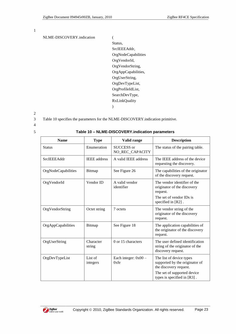
ZigBee Document 094945r00ZB, January, 2010 ZigBee RF4CE Specification
Copyright 2010, ZigBee Standards Organization. All rights reserved. Page 23
1
NLME-DISCOVERY.indication (
Status,
SrcIEEEAddr,
OrgNodeCapabilities
OrgVendorId,
OrgVendorString,
OrgAppCapabilities,
OrgUserString,
OrgDevTypeList,
OrgProfileIdList,
SearchDevType,
RxLinkQuality
)
2
Table 10 specifies the parameters for the NLME-DISCOVERY.indication primitive. 3
4
Table 10 – NLME-DISCOVERY.indication parameters 5
Name Type Valid range Description
Status Enumeration SUCCESS or
NO_REC_CAPACITY
The status of the pairing table.
SrcIEEEAddr IEEE address A valid IEEE address The IEEE address of the device
requesting the discovery.
OrgNodeCapabilities Bitmap See Figure 26 The capabilities of the originator
of the discovery request.
OrgVendorId Vendor ID A valid vendor
identifier
The vendor identifier of the
originator of the discovery
request.
The set of vendor IDs is
specified in [R2] .
OrgVendorString Octet string 7 octets The vendor string of the
originator of the discovery
request.
OrgAppCapabilities Bitmap See Figure 18 The application capabilities of
the originator of the discovery
request.
OrgUserString Character
string
0 or 15 characters The user defined identification
string of the originator of the
discovery request.
OrgDevTypeList List of
integers
Each integer: 0x00 –
0xfe
The list of device types
supported by the originator of
the discovery request.
The set of supported device
types is specified in [R3] .

ZigBee RF4CE Specification ZigBee Document 094945r00ZB, January, 2010
Page 24 Copyright 2010, ZigBee Standards Organization. All rights reserved.
Name Type Valid range Description
OrgProfileIdList List of
integers
Each integer: 0x00 –
0xff
The list of profile identifiers
supported by the originator of
the discovery request.
The set of supported profile
identifiers is specified in [R4]
SearchDevType Integer 0x00 – 0xff The device type being
discovered.
If this is 0xff, any type is being
requested.
RxLinkQuality Integer 0x00 – 0xff LQI value, as passed via the
MAC sub-layer, of the discovery
request command frame.
1
3.1.2.5.2 When generated 2
The NLME-DISCOVERY.indication primitive is generated by the NLME and issued to the application 3
to indicate the reception of a discovery request command frame. 4
If the NLME has spare capacity in its pairing table for a potential pairing link with this device, it issues 5
the primitive with a status of SUCCESS. If the NLME does not have capacity in its pairing table, it 6
issues the primitive with a status of NO_REC_CAPACITY. 7
3.1.2.5.3 Effect on receipt 8
On receipt of the NLME-DISCOVERY.indication primitive, the application decides whether to 9
respond based on the information contained in the primitive. The decision to respond, i.e. whether the 10
discovery request matches the capabilities of this node, is out of the scope of this specification. 11
If the application decides to respond, it issues the NLME-DISCOVERY.response primitive with the 12
source IEEE address and LQI from the received discovery request command frame, contained in this 13
primitive, its own device type and the status value received in the NLME-DISCOVERY.indication 14
primitive. 15
If the application decides not to respond, no primitive is issued. 16
17
3.1.2.6 NLME-DISCOVERY.response 18
The NLME-DISCOVERY.response primitive allows the application to request that the NLME respond 19
to the discovery request command. 20
3.1.2.6.1 Semantics of the service primitive 21
The semantics of the NLME-DISCOVERY.response primitive are as follows: 22
23
NLME-DISCOVERY.response (
Status,
DstIEEEAddr,
RecAppCapabilities,
RecDevTypeList,
RecProfileIdList,
DiscReqLQI
)
24
Table 11 specifies the parameters for the NLME-DISCOVERY.response primitive. 25

ZigBee Document 094945r00ZB, January, 2010 ZigBee RF4CE Specification
Copyright 2010, ZigBee Standards Organization. All rights reserved. Page 25
1
Table 11 – NLME-DISCOVERY.response parameters 2
Name Type Valid range Description
Status Enumeration SUCCESS or
NO_REC_CAPACI
TY
The status of the discovery
request.
DstIEEEAddr IEEE address Valid IEEE address The IEEE address of the device
requesting discovery.
RecAppCapabilities Bitmap See Figure 18 The application capabilities of
the node issuing this primitive.
RecDevTypeList List of integers Each integer: 0x00
– 0xfe
The list of device types
supported by the node issuing
this primitive.
The set of supported device
types is specified in [R3] .
RecProfileIdList List of integers Each integer: 0x00
– 0xff
The list of profile identifiers
supported by the node issuing
this primitive.
The set of supported profile
identifiers is specified in [R4]
DiscReqLQI Integer 0x00 – 0xff The LQI value from the
associated NLME-
DISCOVERY.indication
primitive.
3
3.1.2.6.2 When generated 4
The NLME-DISCOVERY.response primitive is generated by the application and issued to its NLME 5
in response to an NLME-DISCOVERY.indication primitive. 6
3.1.2.6.3 Effect on receipt 7
On receipt of this primitive, the NLME generates a discovery response command frame (see 3.3.2). 8
The NLME transmits the frame on its current channel by issuing the MCPS-DATA.request primitive to 9
the MAC sub-layer. 10
On receipt of an MCPS-DATA.confirm primitive from the MAC sub-layer, the NLME issues the 11
NLME-COMM-STATUS.indication primitive with the status value contained in the primitive. 12
13
3.1.2.7 NLME-DISCOVERY.confirm 14
The NLME-DISCOVERY.confirm primitive allows the NLME to notify the application of the status of 15
its request to perform a network discovery. 16
3.1.2.7.1 Semantics of the service primitive 17
The semantics of the NLME-DISCOVERY.confirm primitive are as follows: 18
19

ZigBee RF4CE Specification ZigBee Document 094945r00ZB, January, 2010
Page 26 Copyright 2010, ZigBee Standards Organization. All rights reserved.
NLME-DISCOVERY.confirm (
Status,
NumNodes,
NodeDescList
)
1
Table 12 specifies the parameters for the NLME-DISCOVERY.confirm primitive. 2
3
Table 12 – NLME-DISCOVERY.confirm parameters 4
Name Type Valid range Description
Status Enumeration SUCCESS,
DISCOVERY_ERROR,
DISCOVERY_TIMEOUT or
anything returned from the
MCPS-DATA.confirm
primitive
The status of the network
discovery attempt.
NumNodes 8-bit integer 0x00 - nwkcMaxNode-
DescListSize
The number of discovered
nodes in the
NodeDescList parameter.
NodeDescList NodeDesc See Table 13 The list of node
descriptors discovered.
5
Table 13 describes the elements of the NodeDesc type. 6
7
Table 13 – Elements of the NodeDesc type 8
Name Type Valid range Description
Status Enumeration SUCCESS or
NO_REC_CAPACITY
The status of the discovery request as
reported by the responding device.
LogicalChannel 8-bit integer See 3.5.1.1 The logical channel of the responding
device.
PANId PAN identifier A valid PAN identifier The PAN identifier of the responding
device.
IEEEAddr IEEE address A valid IEEE address The IEEE address of the responding
device.
NodeCapabilities Bitmap See Figure 26 The capabilities of the responding node.
VendorId Vendor
identifier
A valid vendor
identifier
The vendor identifier of the responding
node.
The set of vendor IDs is specified in
[R2] .
VendorString Octet string 7 octets The vendor string of the responding
node.
AppCapabilities Bitmap See Figure 18 The application capabilities of the
responding node.
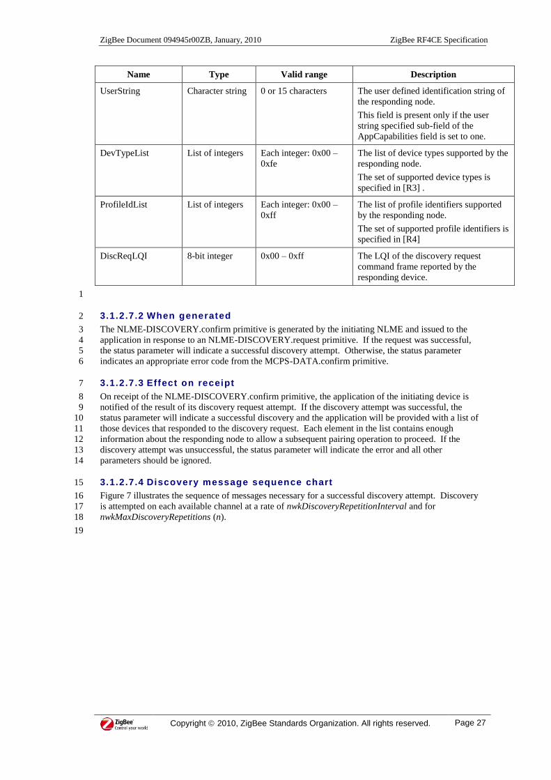
ZigBee Document 094945r00ZB, January, 2010 ZigBee RF4CE Specification
Copyright 2010, ZigBee Standards Organization. All rights reserved. Page 27
Name Type Valid range Description
UserString Character string 0 or 15 characters The user defined identification string of
the responding node.
This field is present only if the user
string specified sub-field of the
AppCapabilities field is set to one.
DevTypeList List of integers Each integer: 0x00 –
0xfe
The list of device types supported by the
responding node.
The set of supported device types is
specified in [R3] .
ProfileIdList List of integers Each integer: 0x00 –
0xff
The list of profile identifiers supported
by the responding node.
The set of supported profile identifiers is
specified in [R4]
DiscReqLQI 8-bit integer 0x00 – 0xff The LQI of the discovery request
command frame reported by the
responding device.
1
3.1.2.7.2 When generated 2
The NLME-DISCOVERY.confirm primitive is generated by the initiating NLME and issued to the 3
application in response to an NLME-DISCOVERY.request primitive. If the request was successful, 4
the status parameter will indicate a successful discovery attempt. Otherwise, the status parameter 5
indicates an appropriate error code from the MCPS-DATA.confirm primitive. 6
3.1.2.7.3 Effect on receipt 7
On receipt of the NLME-DISCOVERY.confirm primitive, the application of the initiating device is 8
notified of the result of its discovery request attempt. If the discovery attempt was successful, the 9
status parameter will indicate a successful discovery and the application will be provided with a list of 10
those devices that responded to the discovery request. Each element in the list contains enough 11
information about the responding node to allow a subsequent pairing operation to proceed. If the 12
discovery attempt was unsuccessful, the status parameter will indicate the error and all other 13
parameters should be ignored. 14
3.1.2.7.4 Discovery message sequence chart 15
Figure 7 illustrates the sequence of messages necessary for a successful discovery attempt. Discovery 16
is attempted on each available channel at a rate of nwkDiscoveryRepetitionInterval and for 17
nwkMaxDiscoveryRepetitions (n). 18
19

ZigBee RF4CE Specification ZigBee Document 094945r00ZB, January, 2010
Page 28 Copyright 2010, ZigBee Standards Organization. All rights reserved.
APL-ORG NWK-ORGNWK-REC(Channel 1)
APL-REC(Channel 1)
NWK-REC(Channel 3)
APL-REC(Channel 3)
Discovery Request
DISCOVERY.indication
DISCOVERY.response
Discovery Response
DISCOVERY.request
DiscDuration
(Channel 1)
DiscDuration
(Channel 3)
DISCOVERY.indication
DISCOVERY.responseDiscovery Response
Discovery Request
DISCOVERY.confirm
...
COMM-STATUS.indication
COMM-STATUS.indication
nwkDiscovery-
RepetitionInterval
(repetition 1)
Discovery Request
DISCOVERY.indication
DISCOVERY.response
Discovery Response
DiscDuration
(Channel 1)
DiscDuration
(Channel 3)
DISCOVERY.indication
DISCOVERY.responseDiscovery Response
Discovery Request...
COMM-STATUS.indication
COMM-STATUS.indication
nwkDiscovery-
RepetitionInterval
(repetition n)
...
1
Figure 7 – Message sequence chart for discovery 2
3
3.1.2.8 NLME-GET.request 4
The NLME-GET.request primitive allows the application to request the value of a NIB attribute from 5
the NLME. 6
3.1.2.8.1 Semantics of the service primitive 7
The semantics of the NLME-GET.request primitive are as follows: 8
9
NLME-GET.request (
NIBAtribute,
NIBAttributeIndex,
)
10
Table 14 specifies the parameters for the NLME-GET.request primitive. 11
12
Table 14 – NLME-GET.request parameters 13
Name Type Valid range Description
NIBAttribute Integer See Table 48 The identifier of the NIB attribute to read.

ZigBee Document 094945r00ZB, January, 2010 ZigBee RF4CE Specification
Copyright 2010, ZigBee Standards Organization. All rights reserved. Page 29
Name Type Valid range Description
NIBAttributeIndex Integer Attribute specific The index within the table or array of the
specified NIB attribute to read. This parameter
is valid only for NIB attributes that are tables
or arrays.
3.1.2.8.2 When generated 1
The NLME-GET.request primitive is generated by the application and issued to the NLME to obtain 2
information from the NIB. 3
3.1.2.8.3 Effect on receipt 4
On receipt of the NLME-GET.request primitive, the NLME checks to see if the NIB attribute exists. If 5
the attribute exists, the NLME attempts to retrieve the requested NIB attribute from its database. If the 6
identifier of the NIB attribute is not found in the database, the NLME will issue the NLME-7
GET.confirm primitive with a status of UNSUPPORTED_ATTRIBUTE. If the NIBAttributeIndex 8
parameter specifies an index for a table that is out of range, the NLME will issue the NLME-9
GET.confirm primitive with a status of INVALID_INDEX. If the requested NIB attribute is 10
successfully retrieved, the NLME will issue the NLME-GET.confirm primitive with a status of 11
SUCCESS and the value of the requested attribute in the NIBAttributeValue parameter. 12
3.1.2.9 NLME-GET.confirm 13
The NLME-GET.confirm primitive allows the NLME to notify the application of the status of its 14
request for the value of a NIB attribute. 15
3.1.2.9.1 Semantics of the service primitive 16
The semantics of the NLME-GET.confirm primitive are as follows: 17
18
NLME-GET.confirm (
Status,
NIBAttribute,
NIBAttributeIndex,
NIBAttributeValue
)
19
Table 15 specifies the parameters for the NLME-GET.confirm primitive. 20
21
Table 15 – NLME-GET.confirm parameters 22
Name Type Valid range Description
Status Enumeration SUCCESS,
UNSUPPORTED_-
ATTRIBUTE or
INVALID INDEX
The status of the request for NIB attribute
information.
NIBAttribute Integer See Table 48 The identifier of the NIB attribute that was
read.
NIBAttributeIndex Integer Attribute specific The index within the table or array of the
specified NIB attribute that was read. This
parameter is valid only for NIB attributes
that are tables or arrays.

ZigBee RF4CE Specification ZigBee Document 094945r00ZB, January, 2010
Page 30 Copyright 2010, ZigBee Standards Organization. All rights reserved.
Name Type Valid range Description
NIBAttributeValue Various Attribute specific The value of the NIB attribute that was
read.
This value has a zero length when the
Status parameter is not equal to
SUCCESS.
3.1.2.9.2 When generated 1
The NLME-GET.confirm primitive is generated by the NLME and issued to the application in response 2
to an NLME-GET.request primitive. This primitive returns a status of either SUCCESS, indicating that 3
the request to read a NIB attribute was successful, or an error code of INVALID_INDEX or 4
UNSUPPORTED_ATTRIBUTE. The status values are fully described in 3.1.2.6.3. 5
3.1.2.9.3 Effect on receipt 6
On receipt of the NLME-GET.confirm primitive, the application is notified of the results of its request 7
to read a NIB attribute. If the request to read a NIB attribute was successful, the status parameter will 8
be set to SUCCESS. Otherwise, the status parameter indicates the error. 9
10
3.1.2.10 NLME-PAIR.request 11
The NLME-PAIR.request primitive allows the application to request the NLME pair with another 12
device. This primitive would normally be issued following a discovery operation via the NLME-13
DISCOVERY.request primitive. 14
3.1.2.10.1 Semantics of the service primitive 15
The semantics of the NLME-PAIR.request primitive are as follows: 16
17
NLME-PAIR.request (
LogicalChannel,
DstPANId,
DstIEEEAddr,
OrgAppCapabilities,
OrgDevTypeList,
OrgProfileIdList,
KeyExTransferCount
)
18
Table 16 specifies the parameters for the NLME-PAIR.request primitive. 19
20
Table 16 – NLME-PAIR.request parameters 21
Name Type Valid range Description
LogicalChannel Integer See 3.5.1.1 The logical channel of the device with
which to pair.
DstPANId PAN
identifier
A valid PAN
identifier
The PAN identifier of the device with
which to pair.
DstIEEEAddr IEEE
address
A valid IEEE
address
The IEEE address of the device with
which to pair.

ZigBee Document 094945r00ZB, January, 2010 ZigBee RF4CE Specification
Copyright 2010, ZigBee Standards Organization. All rights reserved. Page 31
Name Type Valid range Description
OrgAppCapabilities Bitmap See Figure 18 The application capabilities of the node
issuing this primitive.
OrgDevTypeList List of
integers
Each integer:
0x00 – 0xfe
The list of device types supported by the
node issuing this primitive.
The set of supported device types is
specified in [R3] .
OrgProfileIdList List of
integer
Each integer:
0x00 – 0xff
The list of profile identifiers supported
by the node issuing this primitive.
The set of supported profile identifiers is
specified in [R4]
KeyExTransferCount Integer 0x00 – 0xff The number of transfers the target should
use to exchange the link key with the
pairing originator.
1
3.1.2.10.2 When generated 2
The NLME-PAIR.request primitive is generated by the local application entity and issued to the NLME 3
to request a pairing operation. 4
3.1.2.10.3 Effect on receipt 5
On receipt of the NLME-PAIR.request primitive, the NLME checks whether the requested pairing link 6
is a duplicate of an already existing pairing table entry. If a duplicate entry exists, that pairing table 7
entry will be updated. If a duplicate entry does not exist, the NLME checks whether it has capacity in 8
its pairing table to store the potential new pairing link. If the NLME has no capacity in its pairing 9
table, it issues the NLME-PAIR.confirm primitive with a status of NO_ORG_CAPACITY and 10
performs no further processing. 11
The NLME then generates a pair request command (see 3.3.3), with the information supplied in the 12
primitive. Before the NLME transmits the frame, it changes phyCurrentChannel to the requested 13
channel by issuing the MLME-SET.request command to the MAC sub-layer. Finally, the NLME 14
transmits the pair request command by issuing the MCPS-DATA.request primitive to the MAC sub-15
layer. 16
If the MAC sub-layer fails to transmit the frame (i.e. a status of anything but SUCCESS is returned 17
from the MCPS-DATA.confirm primitive), the NLME switches to the next channel and repeats the 18
procedure. The transmission attempt is made on each available channel until it is successful or until all 19
channels have been attempted. If the transmission is still not successful, the NLME issues the NLME-20
PAIR.confirm primitive with the status value returned from the MAC sub-layer and performs no 21
further processing. 22
If the MAC sub-layer successfully transmits the frame, the NLME waits nwkResponseWaitTime 23
symbols for the corresponding pair response command (see 3.3.4) to arrive. If a pair response 24
command is not received within this time, the NLME issues the NLME-PAIR.confirm primitive with a 25
status of NO_RESPONSE and performs no further processing. 26
On receipt of a pair response command frame with a status field not equal to SUCCESS, the NLME 27
issues the NLME-PAIR.confirm primitive with a status equal to that received in the pair response 28
command frame and performs no further processing. 29
On receipt of a pair response command frame with a status field equal to SUCCESS, the NLME creates 30
a new entry or updates an existing entry, as determined above, in the pairing table with the information 31
contained in the pair response command frame and marks it as provisional. 32
The NLME then checks whether security is required for this pairing link. If security is not required for 33
this pairing link the NLME moves the pairing link from provisional to active and issues the NLME-34
PAIR.confirm primitive with the pairing table index at which the pairing link was created or updated 35
and a status of SUCCESS and performs no further processing. 36

ZigBee RF4CE Specification ZigBee Document 094945r00ZB, January, 2010
Page 32 Copyright 2010, ZigBee Standards Organization. All rights reserved.
If security is required for this pairing link, the NLME waits for the reception of (n + 1) key seed 1
command frames from the target, where n is equal to the value of the KeyExTransferCount parameter. 2
If all the transfers are not received within ((n + 1) * nwkcMaxKeySeedWaitTime) symbols, the NLME 3
removes the provisional pairing link, issues the NLME-PAIR.confirm primitive with a status of 4
SECURITY_TIMEOUT and performs no further processing. 5
If all the transfers are received within ((n + 1) * nwkcMaxKeySeedWaitTime) symbols, the NLME 6
generates a ping request command (see 3.3.7) and transmits it to the pairing recipient by issuing the 7
MCPS-DATA.request primitive to the MAC sub-layer. 8
If the MAC sub-layer fails to transmit the frame (i.e. a status of anything but SUCCESS is returned 9
from the MCPS-DATA.confirm primitive), the NLME removes the provisional pairing link, issues the 10
NLME-PAIR.confirm primitive with the status value returned from the MAC sub-layer and performs 11
no further processing. 12
If the MAC sub-layer successfully transmits the frame, the NLME waits nwkResponseWaitTime 13
symbols for the corresponding ping response command (see 3.3.8) to arrive. If a ping response 14
command frame is not received within this time, the NLME removes the provisional pairing link, 15
issues the NLME-PAIR.confirm primitive with a status of NO_RESPONSE and performs no further 16
processing. 17
If a ping response command frame is received within this time, the NLME verifies the information it 18
contains. If the information is not verified, the NLME removes the provisional pairing link, issues the 19
NLME-PAIR.confirm primitive with a status of SECURITY_FAILURE and performs no further 20
processing. If the information is verified, the NLME moves the pairing table entry from provisional to 21
active and issues the NLME-PAIR.confirm primitive with the pairing table index at which the pairing 22
link was created or updated and a status of SUCCESS. 23
3.1.2.11 NLME-PAIR.indicat ion 24
The NLME-PAIR.indication primitive allows the NLME to notify the application of the reception of a 25
pairing request command (see 3.3.3). 26
3.1.2.11.1 Semantics of the service pr imitive 27
The semantics of the NLME-PAIR.indication primitive are as follows: 28
29
NLME-PAIR.indication (
Status,
SrcPANId,
SrcIEEEAddr,
OrgNodeCapabilities,
OrgVendorId,
OrgVendorString,
OrgAppCapabilities,
OrgUserString,
OrgDevTypeList,
OrgProfileIdList,
KeyExTransferCount,
ProvPairingRef,
)
30
Table 17 specifies the parameters for the NLME-PAIR.indication primitive. 31
32

ZigBee Document 094945r00ZB, January, 2010 ZigBee RF4CE Specification
Copyright 2010, ZigBee Standards Organization. All rights reserved. Page 33
Table 17 – NLME-PAIR.indication parameters 1
Name Type Valid range Description
Status Enumeration SUCCESS,
NO_REC_CAPACITY or
DUPLICATE_PAIRING
The status of the
provisional pairing.
SrcPANId PAN identifier A valid PAN identifier The PAN identifier of
the device requesting
the pair.
SrcIEEEAddr IEEE address A valid IEEE address The IEEE address of
the device requesting
the pair.
OrgNodeCapabilties Bitmap See Figure 26 The capabilities of the
originator of the pair
request.
OrgVendorId Vendor ID A valid vendor identifier The vendor identifier
of the originator of the
pair request.
The set of vendor IDs
is specified in [R2] .
OrgVendorString Octet string 7 octets The vendor string of
the originator of the
pair request.
OrgAppCapabilities Bitmap See Figure 18 The application
capabilities of the
originator of the pair
request.
OrgUserString Character
string
0 or 15 characters The user defined
identification string of
the originator of the
pair request.
OrgDevTypeList List of integers Each integer: 0x00 – 0xfe The list of device
types supported by the
originator of the pair
request.
The set of supported
device types is
specified in [R3] .
OrgProfileIdList List of integers Each integer: 0x00 – 0xff The list of profile
identifiers supported
by the originator of
the pair request.
The set of supported
profile identifiers is
specified in [R4]
KeyExTransferCount Integer 0x00 – 0xff The number of
transfers being
requested to exchange
the link key with the
pairing originator.
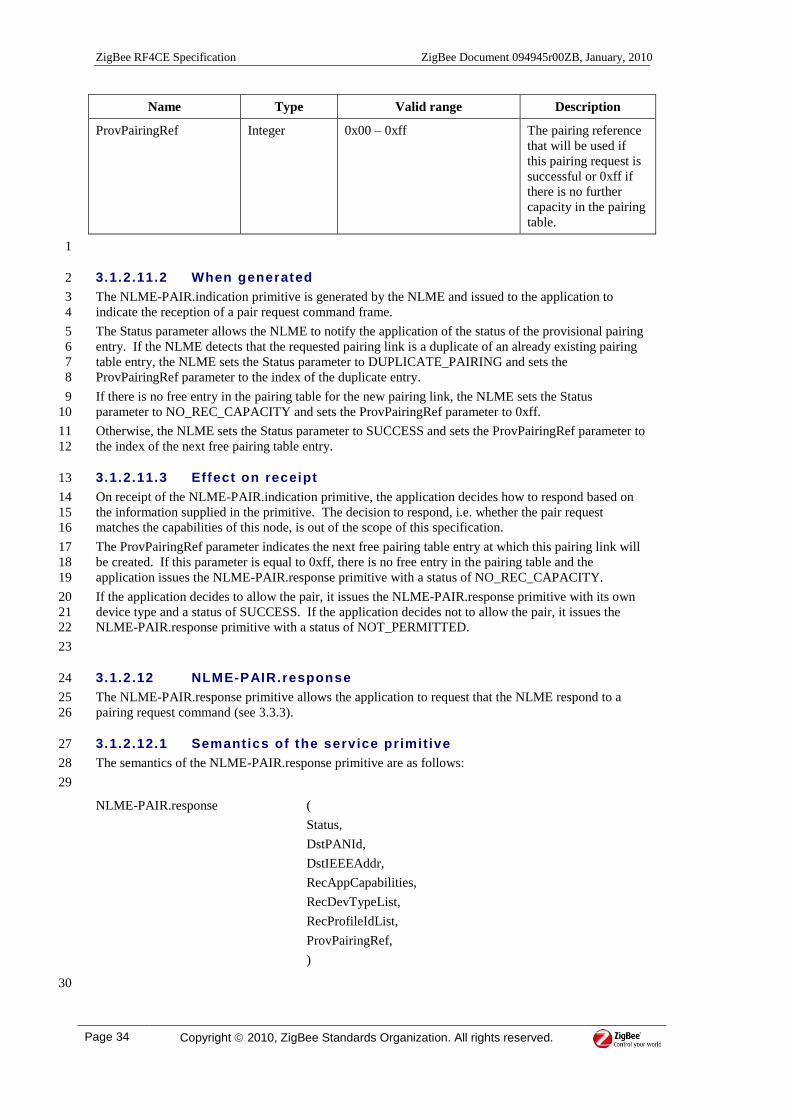
ZigBee RF4CE Specification ZigBee Document 094945r00ZB, January, 2010
Page 34 Copyright 2010, ZigBee Standards Organization. All rights reserved.
Name Type Valid range Description
ProvPairingRef Integer 0x00 – 0xff The pairing reference
that will be used if
this pairing request is
successful or 0xff if
there is no further
capacity in the pairing
table.
1
3.1.2.11.2 When generated 2
The NLME-PAIR.indication primitive is generated by the NLME and issued to the application to 3
indicate the reception of a pair request command frame. 4
The Status parameter allows the NLME to notify the application of the status of the provisional pairing 5
entry. If the NLME detects that the requested pairing link is a duplicate of an already existing pairing 6
table entry, the NLME sets the Status parameter to DUPLICATE_PAIRING and sets the 7
ProvPairingRef parameter to the index of the duplicate entry. 8
If there is no free entry in the pairing table for the new pairing link, the NLME sets the Status 9
parameter to NO_REC_CAPACITY and sets the ProvPairingRef parameter to 0xff. 10
Otherwise, the NLME sets the Status parameter to SUCCESS and sets the ProvPairingRef parameter to 11
the index of the next free pairing table entry. 12
3.1.2.11.3 Effect on receipt 13
On receipt of the NLME-PAIR.indication primitive, the application decides how to respond based on 14
the information supplied in the primitive. The decision to respond, i.e. whether the pair request 15
matches the capabilities of this node, is out of the scope of this specification. 16
The ProvPairingRef parameter indicates the next free pairing table entry at which this pairing link will 17
be created. If this parameter is equal to 0xff, there is no free entry in the pairing table and the 18
application issues the NLME-PAIR.response primitive with a status of NO_REC_CAPACITY. 19
If the application decides to allow the pair, it issues the NLME-PAIR.response primitive with its own 20
device type and a status of SUCCESS. If the application decides not to allow the pair, it issues the 21
NLME-PAIR.response primitive with a status of NOT_PERMITTED. 22
23
3.1.2.12 NLME-PAIR.response 24
The NLME-PAIR.response primitive allows the application to request that the NLME respond to a 25
pairing request command (see 3.3.3). 26
3.1.2.12.1 Semantics of the service primitive 27
The semantics of the NLME-PAIR.response primitive are as follows: 28
29
NLME-PAIR.response (
Status,
DstPANId,
DstIEEEAddr,
RecAppCapabilities,
RecDevTypeList,
RecProfileIdList,
ProvPairingRef,
)
30

ZigBee Document 094945r00ZB, January, 2010 ZigBee RF4CE Specification
Copyright 2010, ZigBee Standards Organization. All rights reserved. Page 35
Table 18 specifies the parameters for the NLME-PAIR.response primitive. 1
2
Table 18 – NLME-PAIR.response parameters 3
Name Type Valid range Description
Status Enumeration SUCCESS,
NO_REC_CAPACITY
or NOT_PERMITTED
The status of the pairing
request.
DstPANId PAN identifier A valid PAN identifier The PAN identifier of the
device requesting the pair.
DstIEEEAddr IEEE address A valid IEEE address The IEEE address of the
device requesting the pair.
RecAppCapabilities Bitmap See Figure 18 The application capabilities
of the node issuing this
primitive.
RecDevTypeList List of integers Each integer:
0x00 – 0xfe
The list of device types
supported by the node
issuing this primitive.
The set of supported device
types is specified in [R3] .
RecProfileIdList List of integers Each integer:
0x00 – 0xff
The list of profile
identifiers supported by the
node issuing this primitive.
The set of supported profile
identifiers is specified in
[R4]
ProvPairingRef Integer 0x00 – 0xff The reference to the
provisional pairing entry if
the pair was accepted or
0xff otherwise.
4
3.1.2.12.2 When generated 5
The NLME-PAIR.response primitive is generated by the application and issued to its NLME in 6
response to an NLME-PAIR.indication primitive. 7
3.1.2.12.3 Effect on receipt 8
On receipt of this primitive and if the Status parameter is equal to SUCCESS, the NLME updates the 9
entry in the pairing table corresponding to the ProvPairingRef parameter by specifying a network 10
address for the originator of the pairing link. If the capabilities of the originator node indicate that it is 11
a controller device, the NLME allocates a network address for that device. Otherwise, the network 12
address is specified as 0xfffe. 13
The NLME then generates a pair response command frame (see 3.3.4). The NLME transmits the frame 14
on its current channel by issuing the MCPS-DATA.request primitive to the MAC sub-layer. 15
On receipt of an MCPS-DATA.confirm primitive from the MAC sub-layer with a status of anything 16
but SUCCESS, the NLME issues the NLME-COMM-STATUS.indication primitive with the status 17
value contained in the MCPS-DATA.confirm primitive, removes the provisional pairing link and 18
performs no further processing. 19
If an MCPS-DATA.confirm primitive is received from the MAC sub-layer with a status of SUCCESS 20
but the application did not accept the pair (i.e. the Status parameter of the NLME-PAIR.response 21

ZigBee RF4CE Specification ZigBee Document 094945r00ZB, January, 2010
Page 36 Copyright 2010, ZigBee Standards Organization. All rights reserved.
primitive was not equal to SUCCESS), the NLME removes the provisional pairing link and performs 1
no further processing. 2
If an MCPS-DATA.confirm primitive is received from the MAC sub-layer with a status of SUCCESS 3
and the application accepted the pair (i.e. the Status parameter of the NLME-PAIR.response primitive 4
was equal to SUCCESS), the NLME determines whether security is required for this pairing link. If 5
security is not required for this pairing link, the NLME issues the NLME-COMM-STATUS.indication 6
primitive with a status value of SUCCESS, moves the pairing link from provisional to active and 7
performs no further processing. 8
If security is required for this pairing link, the NLME generates a security link key and attempts to 9
transfer it to the originator. To transfer the key, the NLME sends (n + 1) key seed command frames to 10
the pairing originator, where n is equal to the value of the key exchange transfer count field of the pair 11
request command frame. 12
If all the transfers do not complete within ((n + 1) * nwkcMaxKeySeedWaitTime) symbols, the NLME 13
issues the NLME-COMM-STATUS.indication primitive with a status of SECURITY_TIMEOUT, 14
removes the provisional pairing link and performs no further processing. 15
If all the transfers complete within ((n + 1) * nwkcMaxKeySeedWaitTime) symbols, the NLME waits 16
for at most nwkResponseWaitTime to receive a ping request command frame from the originator of the 17
pair request command frame. If a ping request command frame is not received within 18
nwkResponseWaitTime, the NLME issues the NLME-COMM-STATUS.indication primitive with a 19
status of SECURITY_FAILURE, removes the provisional pairing link and performs no further 20
processing. 21
If a ping request command frame is received within nwkResponseWaitTime, the NLME verifies the 22
data contained in the ping request command frame. If the ping request command frame cannot be 23
verified in this way, the NLME issues the NLME-COMM-STATUS.indication primitive with a status 24
of SECURITY_FAILURE, removes the provisional pairing link and performs no further processing. 25
If the ping request command frame was verified as described above, the NLME generates a ping 26
response command frame and transmits it back to the originator of the ping request command frame by 27
issuing the MCPS-DATA.request primitive to the MAC sub-layer. 28
On receipt of an MCPS-DATA.confirm primitive from the MAC sub-layer with a status other than 29
SUCCESS, the NLME issues the NLME-COMM-STATUS.indication primitive with the value 30
returned from the MAC sub-layer, removes the provisional pairing link and performs no further 31
processing. 32
On receipt of an MCPS-DATA.confirm primitive from the MAC sub-layer with a status of SUCCESS, 33
the NLME issues the NLME-COMM-STATUS.indication primitive with a status value of SUCCESS 34
and then moves the pairing link from provisional to active. 35
3.1.2.13 NLME-PAIR.confirm 36
The NLME-PAIR.confirm primitive allows the NLME to notify the application of the status of its 37
request to pair with another device. 38
3.1.2.13.1 Semantics of the service primitive 39
The semantics of the NLME-PAIR.confirm primitive are as follows: 40
41

ZigBee Document 094945r00ZB, January, 2010 ZigBee RF4CE Specification
Copyright 2010, ZigBee Standards Organization. All rights reserved. Page 37
NLME-PAIR.confirm (
Status,
PairingRef,
RecVendorId,
RecVendorString,
RecAppCapabilities,
RecUserString,
RecDevTypeList,
RecProfileIdList
)
1
Table 19 specifies the parameters for the NLME-PAIR.confirm primitive. 2
3
Table 19 – NLME-PAIR.confirm parameters 4
Name Type Valid range Description
Status Enumeration SUCCESS,
NO_ORG_CAPACITY,
NO_REC_CAPACITY,
NO_RESPONSE,
NOT_PERMITTED,
SECURITY_FAILURE,
SECURITY_TIMEOUT or
anything returned from the
MCPS-DATA.confirm
primitive.
The status of the pair
attempt.
PairingRef Integer 0x00 – 0xff The pairing table
reference for this
pairing link.
If the Status parameter
is not equal to
SUCCESS, this value
will be equal to 0xff.
RecVendorId Vendor ID A valid vendor identifier The vendor identifier
of the originator of the
pair response.
The set of vendor IDs
is specified in [R2] .
RecVendorString Octet string 7 octets The vendor string of
the originator of the
pair response.
RecAppCapabilities Bitmap See Figure 18 The application
capabilities of the
originator of the pair
response.
RecUserString Character
string
0 or 15 characters The user defined
identification string of
the originator of the
pair response.

ZigBee RF4CE Specification ZigBee Document 094945r00ZB, January, 2010
Page 38 Copyright 2010, ZigBee Standards Organization. All rights reserved.
Name Type Valid range Description
RecDevTypeList List of integers Each integer:
0x00 – 0xfe
The list of device
types supported by the
originator of the pair
response.
The set of supported
device types is
specified in [R3] .
RecProfileIdList List of integers Each integer:
0x00 – 0xff
The list of profile
identifiers supported
by the originator of
the pair response.
The set of supported
profile identifiers is
specified in [R4]
1
3.1.2.13.2 When generated 2
The NLME-PAIR.confirm primitive is generated by the initiating NLME and issued to the application 3
in response to an NLME-PAIR.request primitive. If the request was successful, the status parameter 4
will indicate a successful pair, as contained in the Status field of the pair response command frame (see 5
3.3.4). Otherwise, the status parameter indicates either an error code from the received pair response 6
command frame or an appropriate error code from the MCPS-DATA.confirm primitive. 7
3.1.2.13.3 Effect on receipt 8
On receipt of the NLME-PAIR.confirm primitive, the application of the originating device is notified 9
of the result of its pair request. If the pair attempt was successful, the status parameter will indicate a 10
successful pair, as contained in the Status field of the pair response command frame, and the device 11
will be provided with the pairing reference on which the pair was created. If the pair attempt was 12
unsuccessful, the status parameter will indicate the error and all other parameters are invalid. 13
3.1.2.13.4 Pairing message sequence chart 14
Figure 8 illustrates the sequence of messages necessary for a successful pairing attempt. Note that this 15
message sequence chart also illustrates the security key exchange procedure which is only included if 16
the nodes at both ends of the pairing link can support security. 17
18
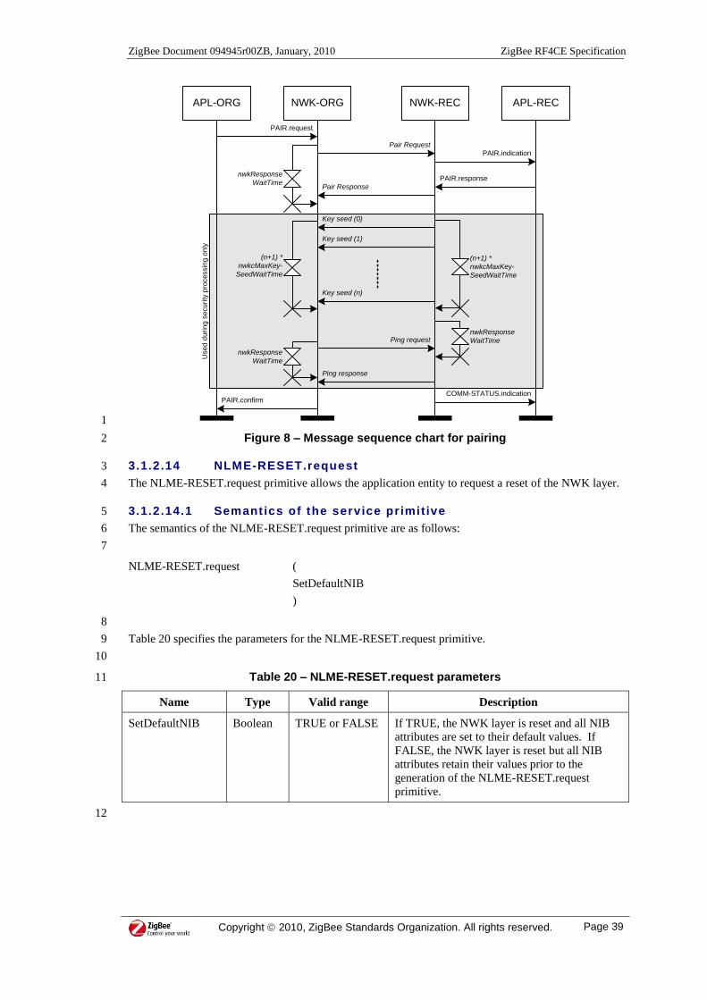
ZigBee Document 094945r00ZB, January, 2010 ZigBee RF4CE Specification
Copyright 2010, ZigBee Standards Organization. All rights reserved. Page 39
APL-ORG NWK-ORG NWK-REC APL-REC
Pair Request
PAIR.indication
PAIR.response
Pair Response
PAIR.request
nwkResponse
WaitTime
PAIR.confirmCOMM-STATUS.indication
Key seed (0)
(n+1) *
nwkcMaxKey-
SeedWaitTime
Key seed (1)
(n+1) *
nwkcMaxKey-
SeedWaitTime
Key seed (n)
Ping request
Ping response
nwkResponse
WaitTime
nwkResponse
WaitTime
Use
d d
urin
g s
ecu
rity
pro
ce
ssin
g o
nly
1
Figure 8 – Message sequence chart for pairing 2
3.1.2.14 NLME-RESET.request 3
The NLME-RESET.request primitive allows the application entity to request a reset of the NWK layer. 4
3.1.2.14.1 Semantics of the service primitive 5
The semantics of the NLME-RESET.request primitive are as follows: 6
7
NLME-RESET.request (
SetDefaultNIB
)
8
Table 20 specifies the parameters for the NLME-RESET.request primitive. 9
10
Table 20 – NLME-RESET.request parameters 11
Name Type Valid range Description
SetDefaultNIB Boolean TRUE or FALSE If TRUE, the NWK layer is reset and all NIB
attributes are set to their default values. If
FALSE, the NWK layer is reset but all NIB
attributes retain their values prior to the
generation of the NLME-RESET.request
primitive.
12
ZigBee RF4CE Specification ZigBee Document 094945r00ZB, January, 2010
Page 40 Copyright 2010, ZigBee Standards Organization. All rights reserved.
3.1.2.14.2 When generated 1
The NLME-RESET.request primitive is generated by the application and issued to the NLME to 2
request a reset of the NWK layer to its initial conditions. The NLME-RESET.request primitive is 3
issued prior to the use of the NLME-START.request primitive. 4
3.1.2.14.3 Effect on receipt 5
On receipt of the NLME-RESET.request primitive, the NLME issues the MLME-RESET.request 6
primitive with the SetDefaultPIB parameter set to the value of the SetDefaultNIB parameter. On 7
receipt of the MLME-RESET.confirm primitive, the NWK layer is then set to its initial conditions, 8
clearing all internal variables to their default values. If the SetDefaultNIB parameter is set to TRUE, 9
the NIB attributes are set to their default values. 10
Note: issuing this primitive with the SetDefaultNIB parameter set to TRUE will remove all entries 11
from the pairing table. 12
13
3.1.2.15 NLME-RESET.confirm 14
The NLME-RESET.confirm primitive allows the NLME to notify the application of the status of its 15
request to reset the NWK layer. 16
3.1.2.15.1 Semantics of the service primitive 17
The semantics of the NLME-RESET.confirm primitive are as follows: 18
19
NLME-RESET.confirm (
Status
)
20
Table 21specifies the parameters for the NLME-RESET.confirm primitive. 21
22
Table 21 – NLME-RESET.confirm parameters 23
Name Type Valid range Description
Status Enumeration SUCCESS The status of the reset request.
24
3.1.2.15.2 When generated 25
The NLME-RESET.confirm primitive is generated by the NLME and issued to the application in 26
response to an NLME-RESET.request primitive. 27
3.1.2.15.3 Effect on receipt 28
On receipt of the NLME-RESET.confirm primitive, the application is notified of its request to reset the 29
NWK layer. This primitive returns a status of SUCCESS indicating that the request to reset the NWK 30
layer was successful. 31
32
3.1.2.16 NLME-RX-ENABLE.request 33
The NLME-RX-ENABLE.request primitive allows the application to request that the receiver is either 34
enabled (for a finite period or until further notice) or disabled. 35
3.1.2.16.1 Semantics of the service primitive 36
The semantics of the NLME-RX-ENABLE.request primitive are as follows: 37
38
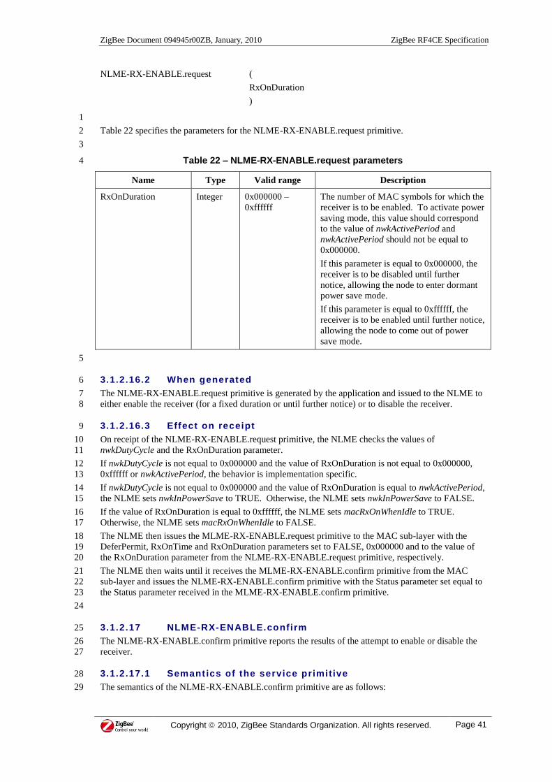
ZigBee Document 094945r00ZB, January, 2010 ZigBee RF4CE Specification
Copyright 2010, ZigBee Standards Organization. All rights reserved. Page 41
NLME-RX-ENABLE.request (
RxOnDuration
)
1
Table 22 specifies the parameters for the NLME-RX-ENABLE.request primitive. 2
3
Table 22 – NLME-RX-ENABLE.request parameters 4
Name Type Valid range Description
RxOnDuration Integer 0x000000 –
0xffffff
The number of MAC symbols for which the
receiver is to be enabled. To activate power
saving mode, this value should correspond
to the value of nwkActivePeriod and
nwkActivePeriod should not be equal to
0x000000.
If this parameter is equal to 0x000000, the
receiver is to be disabled until further
notice, allowing the node to enter dormant
power save mode.
If this parameter is equal to 0xffffff, the
receiver is to be enabled until further notice,
allowing the node to come out of power
save mode.
5
3.1.2.16.2 When generated 6
The NLME-RX-ENABLE.request primitive is generated by the application and issued to the NLME to 7
either enable the receiver (for a fixed duration or until further notice) or to disable the receiver. 8
3.1.2.16.3 Effect on receipt 9
On receipt of the NLME-RX-ENABLE.request primitive, the NLME checks the values of 10
nwkDutyCycle and the RxOnDuration parameter. 11
If nwkDutyCycle is not equal to 0x000000 and the value of RxOnDuration is not equal to 0x000000, 12
0xffffff or nwkActivePeriod, the behavior is implementation specific. 13
If nwkDutyCycle is not equal to 0x000000 and the value of RxOnDuration is equal to nwkActivePeriod, 14
the NLME sets nwkInPowerSave to TRUE. Otherwise, the NLME sets nwkInPowerSave to FALSE. 15
If the value of RxOnDuration is equal to 0xffffff, the NLME sets macRxOnWhenIdle to TRUE. 16
Otherwise, the NLME sets macRxOnWhenIdle to FALSE. 17
The NLME then issues the MLME-RX-ENABLE.request primitive to the MAC sub-layer with the 18
DeferPermit, RxOnTime and RxOnDuration parameters set to FALSE, 0x000000 and to the value of 19
the RxOnDuration parameter from the NLME-RX-ENABLE.request primitive, respectively. 20
The NLME then waits until it receives the MLME-RX-ENABLE.confirm primitive from the MAC 21
sub-layer and issues the NLME-RX-ENABLE.confirm primitive with the Status parameter set equal to 22
the Status parameter received in the MLME-RX-ENABLE.confirm primitive. 23
24
3.1.2.17 NLME-RX-ENABLE.confirm 25
The NLME-RX-ENABLE.confirm primitive reports the results of the attempt to enable or disable the 26
receiver. 27
3.1.2.17.1 Semant ics of the service primitive 28
The semantics of the NLME-RX-ENABLE.confirm primitive are as follows: 29

ZigBee RF4CE Specification ZigBee Document 094945r00ZB, January, 2010
Page 42 Copyright 2010, ZigBee Standards Organization. All rights reserved.
1
NLME-RX-ENABLE.confirm (
Status
)
2
Table 23 specifies the parameters for the NLME-RX-ENABLE.confirm primitive. 3
4
Table 23 – NLME-RX-ENABLE.confim parameters 5
Name Type Valid range Description
Status Enumeration As returned by
the MLME-RX-
ENABLE.confirm
primitive
The result of the request to enable or
disable the receiver.
6
3.1.2.17.2 When generated 7
The NLME-RX-ENABLE.confirm primitive is generated by the NLME and issued to the application in 8
response to an NLME-RX-ENABLE.request primitive. 9
3.1.2.17.3 Effect on receipt 10
On receipt of the NLME-RX-ENABLE.confirm primitive, the application is notified of its request to 11
enable or disable the receiver. This primitive returns a status of either SUCCESS, if the request to 12
enable or disable the receiver was successful, or an appropriate error code. 13
3.1.2.17.4 Message sequence chart for changing the state of the 14
receiver 15
Figure 9 illustrates the sequence of messages necessary for manipulating the receiver state in various 16
ways. Figure 9 a) illustrates how the application can enabled the receiver until further notice, e.g. when 17
a target comes out of its power save mode. Figure 9 b) illustrates how the application can disable the 18
receiver until further notice, e.g. when a controller has finished transmitting and wishes to sleep. 19
20

ZigBee Document 094945r00ZB, January, 2010 ZigBee RF4CE Specification
Copyright 2010, ZigBee Standards Organization. All rights reserved. Page 43
APL NWK
SET.confirm
MAC
RX-ENABLE.request(
FALSE, 0x000000, 0xffffff)
SET.request(
macRxOnWhenIdle, TRUE)
RX-ENABLE.request(
0xffffff)
RX-ENABLE.confirm(Status)
RX-ENABLE.confirm(Status)
SET.confirm
SET.request(
macRxOnWhenIdle, FALSE)
RX-ENABLE.request(
0x000000)
RX-ENABLE.confirm(Status)
RX-ENABLE.confirm(Status)
RX-ENABLE.request(
FALSE, 0x000000, 0x000000)
a)
b)
1
Figure 9 – Message sequence chart for manipulating the receiver 2
3
3.1.2.18 NLME-SET.request 4
The NLME-SET.request primitive allows the application to request the NLME change the value of a 5
NIB attribute. 6
3.1.2.18.1 Semantics of the service primitive 7
The semantics of the NLME-SET.request primitive are as follows: 8
9
NLME-SET.request (
NIBAtribute,
NIBAttributeIndex,
NIBAttributeValue
)
10
Table 24 specifies the parameters for the NLME-SET.request primitive. 11
12

ZigBee RF4CE Specification ZigBee Document 094945r00ZB, January, 2010
Page 44 Copyright 2010, ZigBee Standards Organization. All rights reserved.
Table 24 – NLME-SET.request parameters 1
Name Type Valid range Description
NIBAttribute Integer See Table 48 The identifier of the NIB attribute to write.
NIBAttributeIndex Integer Attribute specific The index within the table or array of the
specified NIB attribute to write. This
parameter is valid only for NIB attributes that
are tables or arrays.
NIBAttributeValue Various Attribute specific The value of the indicated attribute to write.
2
3.1.2.18.2 When generated 3
The NLME-SET.request primitive is generated by the application and issued to the NLME to write the 4
indicated NIB attribute. 5
3.1.2.18.3 Effect on receipt 6
On receipt of the NLME-SET.request primitive, the NLME checks to see if the NIB attribute exists. If 7
the attribute exists, the NLME attempts to write the given value to the indicated NIB attribute in its 8
database. If the identifier of the NIB attribute is not found in the database, the NLME will issue the 9
NLME-SET.confirm primitive with a status of UNSUPPORTED_ATTRIBUTE. If the 10
NIBAttributeIndex parameter specifies an index for a table that is out of range, the NLME will issue 11
the NLME-SET.confirm primitive with a status of INVALID_INDEX. If the requested NIB attribute 12
is successfully written, the NLME will issue the NLME-SET.confirm primitive with a status of 13
SUCCESS. 14
15
3.1.2.19 NLME-SET.conf irm 16
The NLME-SET.confirm primitive allows the NLME to notify the application of the status of its 17
request to change the value of a NIB attribute. 18
3.1.2.19.1 Semantics of the service primitive 19
The semantics of the NLME-SET.confirm primitive are as follows: 20
21
NLME-SET.confirm (
Status,
NIBAttribute,
NIBAttributeIndex
)
22
Table 25 specifies the parameters for the NLME-SET.confirm primitive. 23
24
Table 25 – NLME-SET.confirm parameters 25
Name Type Valid range Description
Status Enumeration SUCCESS,
UNSUPPORTED_-
ATTRIBUTE or INVALID
INDEX
The status of the request to set
PIB attribute information.
NIBAttribute Integer See Table 48 The identifier of the NIB attribute
that was written.

ZigBee Document 094945r00ZB, January, 2010 ZigBee RF4CE Specification
Copyright 2010, ZigBee Standards Organization. All rights reserved. Page 45
Name Type Valid range Description
NIBAttributeIndex Integer Attribute specific The index within the table or array
of the specified NIB attribute that
was written. This parameter is
valid only for NIB attributes that
are tables or arrays.
1
3.1.2.19.2 When generated 2
The NLME-SET.confirm primitive is generated by the NLME and issued to the application in response 3
to an NLME-SET.request primitive. The NLME-SET.confirm primitive returns a status of either 4
SUCCESS, indicating that the requested value was written to the indicated NIB attribute, or an 5
appropriate error code. The status values are fully described in 3.1.2.18.3. 6
3.1.2.19.3 Effect on receipt 7
On receipt of the NLME-SET.confirm primitive, the application is notified of the result of its request to 8
write the value of a NIB attribute. If the requested value was written to the indicated NIB attribute, the 9
status parameter will be set to SUCCESS. Otherwise, the status parameter indicates the error. 10
11
3.1.2.20 NLME-START.request 12
The NLME-START.request primitive allows the application to request the NLME start a network. 13
3.1.2.20.1 Semantics of the service primitive 14
The semantics of the NLME-START.request primitive are as follows: 15
16
NLME-START.request (
)
17
The NLME-START.request primitive does not have any parameters. 18
3.1.2.20.2 When generated 19
The NLME-START.request primitive is generated by the application and issued to the NLME to 20
request that a device goes through its startup procedure and enter normal operation. 21
3.1.2.20.3 Effect on receipt 22
On receipt of the NLME-START.request primitive, the NLME evaluates the node type field of 23
nwkcNodeCapabilities. If this field indicates that the node is a controller, the NLME performs the 24
general device startup procedure and issues the NLME-START.confirm primitive with a status of 25
SUCCESS. 26
If the node type field of nwkcNodeCapabilities indicates that the node is a target, the NLME first 27
performs the general device startup procedure. The NLME will then issue the MLME-SCAN.request 28
primitive to request the MAC sub-layer perform an energy detect scan with the ScanChannels 29
parameter equal to nwkcChannelMask and the ScanDuration parameter set to nwkScanDuration. On 30
receipt of the MLME-SCAN.confirm primitive, the NLME sets nwkBaseChannel to the channel with 31
the least detected energy. 32
The NLME will then issue the MLME-SCAN.request primitive again to request the MAC sub-layer 33
perform an active scan with the ScanChannels parameter equal to nwkcChannelMask and the 34
ScanDuration parameter set to nwkScanDuration. On receipt of the MLME-SCAN.confirm primitive 35
with a status of SUCCESS or LIMIT_REACHED, the NLME chooses a PAN identifier that is unique 36
across the PANs detected during the active scan and sets macPANId to this value. The device then sets 37
the value of macShortAddress to a randomly generated value in the permitted range. The NLME will 38
then issue the NLME-START.confirm primitive with a status of SUCCESS. 39

ZigBee RF4CE Specification ZigBee Document 094945r00ZB, January, 2010
Page 46 Copyright 2010, ZigBee Standards Organization. All rights reserved.
If either of the two scan requests returns an error, the NLME issues the NLME-START.confirm 1
primitive with a status equal to that returned from the scan that failed. 2
3
3.1.2.21 NLME-START.confirm 4
The NLME-START.confirm primitive allows the NLME to notify the application of the status of its 5
request to start a network. 6
3.1.2.21.1 Semantics of the service primitive 7
The semantics of the NLME-START.confirm primitive are as follows: 8
9
NLME-START.confirm (
Status
)
10
Table 26 specifies the parameters for the NLME-START.confirm primitive. 11
12
Table 26 – NLME-START.confirm parameters 13
Name Type Valid range Description
Status Enumeration SUCCESS or any
error status values
returned from the
MLME-
SCAN.confirm
primitives.
The status of the start attempt.
14
3.1.2.21.2 When generated 15
The NLME-START.confirm primitive is generated by the NLME and issued to the application in 16
response to an NLME-START.request primitive. The NLME-START.confirm primitive returns a 17
status of SUCCESS, indicating that the NWK layer has been initialized and, if a target start was 18
requested, that an RC network has been started. If an error occurred, the status parameter will indicate 19
the error. 20
3.1.2.21.3 Effect on receipt 21
On receipt of the NLME-START.confirm primitive, the application is notified of the result of its 22
request to start operating. If the request was successful, the status parameter will be set to SUCCESS. 23
Otherwise, the status parameter indicates the error. 24
3.1.2.22 NLME-UNPAIR.request 25
The NLME-UNPAIR.request primitive allows the application to request the NLME removes a pairing 26
link with another device both in the local and remote pairing tables. 27
3.1.2.22.1 Semantics of the service primitive 28
The semantics of the NLME-UNPAIR.request primitive are as follows: 29
30
NLME-UNPAIR.request (
PairingRef
)
31

ZigBee Document 094945r00ZB, January, 2010 ZigBee RF4CE Specification
Copyright 2010, ZigBee Standards Organization. All rights reserved. Page 47
Table 27 specifies the parameters for the NLME-UNPAIR.request primitive. 1
2
Table 27 – NLME-UNPAIR.request parameters 3
Name Type Valid range Description
PairingRef Integer 0x00 – 0xfe The reference into the local
pairing table of the entry that is to
be removed.
4
3.1.2.22.2 When generated 5
The NLME-UNPAIR.request primitive is generated by the local application entity and issued to the 6
NLME to request the removal of a pairing link. 7
3.1.2.22.3 Effect on receipt 8
On receipt of the NLME-UNPAIR.request primitive, the NLME searches the pairing table for an entry 9
corresponding to the supplied reference. If no corresponding entry is found, the NLME issues the 10
NLME-UNPAIR.confirm primitive with a status of NO_PAIRING. 11
If a corresponding entry exists in the pairing table, the NLME generates an unpair request command, 12
with the information contained in the pairing table entry. The NLME then transmits the unpair request 13
command frame by issuing the MCPS-DATA.request primitive to the MAC sub-layer. 14
On receipt of the MCPS-DATA.confirm primitive from the MAC sub-layer, the NLME removes the 15
pairing table entry and issues the NLME-UNPAIR.confirm primitive with the same status value 16
returned from the MAC sub-layer. 17
3.1.2.23 NLME-UNPAIR. indication 18
The NLME-UNPAIR.indication primitive allows the NLME to notify the application of the removal of 19
a pairing link by another device. 20
3.1.2.23.1 Semantics of the service primitive 21
The semantics of the NLME-UNPAIR.indication primitive are as follows: 22
23
NLME-UNPAIR.indication (
PairingRef
)
24
Table 28 specifies the parameters for the NLME-UNPAIR.indication primitive. 25
26
Table 28 – NLME-UNPAIR.indication parameters 27
Name Type Valid range Description
PairingRef Integer 0x00 – 0xfe The pairing table reference that
has been removed from the
pairing table.
28
3.1.2.23.2 When generated 29
The NLME-UNPAIR.indication primitive is generated by the NLME and issued to the application to 30
indicate the reception of an unpair request command frame. 31

ZigBee RF4CE Specification ZigBee Document 094945r00ZB, January, 2010
Page 48 Copyright 2010, ZigBee Standards Organization. All rights reserved.
3.1.2.23.3 Effect on receipt 1
On receipt of the NLME-UNPAIR.indication primitive, the application is notified of the removal of the 2
pairing link from the initiating dev ice. At this point, the application may extract information from the 3
pairing table as necessary in order to inform the user. 4
Once the application has all the required information it needs, it issues the NLME-UNPAIR.response 5
primitive with the pairing reference supplied in the NLME-UNPAIR.indication primitive. 6
7
3.1.2.24 NLME-UNPAIR.response 8
The NLME-UNPAIR.response primitive allows the application to notify the NLME that the pairing 9
link indicated via the NLME-UNPAIR.indication primitive can be removed from the pairing table. 10
3.1.2.24.1 Semantics of the service primitive 11
The semantics of the NLME-UNPAIR.response primitive are as follows: 12
13
NLME-UNPAIR.response (
PairingRef
)
14
Table 29 specifies the parameters for the NLME-UNPAIR.response primitive. 15
16
Table 29 – NLME-UNPAIR.response parameters 17
Name Type Valid range Description
PairingRef Integer 0x00 – 0xfe The reference into the local
pairing table of the entry that is to
be removed.
18
3.1.2.24.2 When generated 19
The NLME-UNPAIR.response primitive is generated by the local application entity and issued to the 20
NLME to indicate that a pairing link, previously indicated via the NLME-UNPAIR.indication 21
primitive, can be removed from the pairing table. 22
3.1.2.24.3 Effect on receipt 23
On receipt of the NLME-UNPAIR.response primitive, the NLME removes the entry corresponding to 24
the supplied reference. If no corresponding entry is found, the NLME ignores the primitive. 25
3.1.2.25 NLME-UNPAIR.confirm 26
The NLME-UNPAIR.confirm primitive allows the NLME to notify the application of the status of its 27
request to remove a pair with another device. 28
3.1.2.25.1 Semantics of the service primitive 29
The semantics of the NLME-UNPAIR.confirm primitive are as follows: 30
31
NLME-UNPAIR.confirm (
Status,
PairingRef
)
32
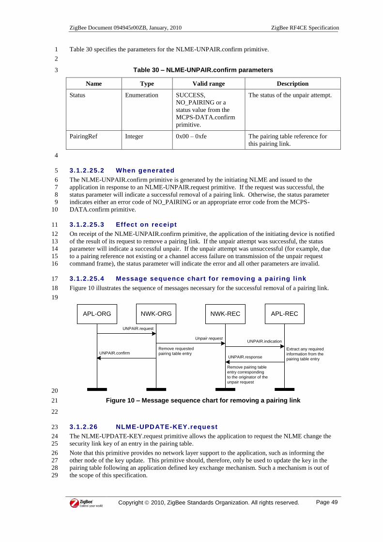
ZigBee Document 094945r00ZB, January, 2010 ZigBee RF4CE Specification
Copyright 2010, ZigBee Standards Organization. All rights reserved. Page 49
Table 30 specifies the parameters for the NLME-UNPAIR.confirm primitive. 1
2
Table 30 – NLME-UNPAIR.confirm parameters 3
Name Type Valid range Description
Status Enumeration SUCCESS,
NO_PAIRING or a
status value from the
MCPS-DATA.confirm
primitive.
The status of the unpair attempt.
PairingRef Integer 0x00 – 0xfe The pairing table reference for
this pairing link.
4
3.1.2.25.2 When generated 5
The NLME-UNPAIR.confirm primitive is generated by the initiating NLME and issued to the 6
application in response to an NLME-UNPAIR.request primitive. If the request was successful, the 7
status parameter will indicate a successful removal of a pairing link. Otherwise, the status parameter 8
indicates either an error code of NO_PAIRING or an appropriate error code from the MCPS-9
DATA.confirm primitive. 10
3.1.2.25.3 Effect on receipt 11
On receipt of the NLME-UNPAIR.confirm primitive, the application of the initiating device is notified 12
of the result of its request to remove a pairing link. If the unpair attempt was successful, the status 13
parameter will indicate a successful unpair. If the unpair attempt was unsuccessful (for example, due 14
to a pairing reference not existing or a channel access failure on transmission of the unpair request 15
command frame), the status parameter will indicate the error and all other parameters are invalid. 16
3.1.2.25.4 Message sequence chart for removing a pairing l ink 17
Figure 10 illustrates the sequence of messages necessary for the successful removal of a pairing link. 18
19
APL-ORG NWK-ORG NWK-REC
Unpair request
UNPAIR.request
UNPAIR.confirm
Remove pairing table
entry corresponding
to the originator of the
unpair request
Remove requested
pairing table entry
APL-REC
UNPAIR.indication
UNPAIR.response
Extract any required
information from the
pairing table entry
20
Figure 10 – Message sequence chart for removing a pairing link 21
22
3.1.2.26 NLME-UPDATE-KEY.request 23
The NLME-UPDATE-KEY.request primitive allows the application to request the NLME change the 24
security link key of an entry in the pairing table. 25
Note that this primitive provides no network layer support to the application, such as informing the 26
other node of the key update. This primitive should, therefore, only be used to update the key in the 27
pairing table following an application defined key exchange mechanism. Such a mechanism is out of 28
the scope of this specification. 29
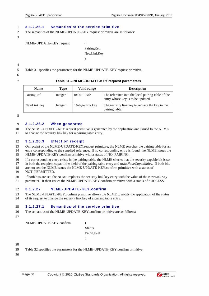
ZigBee RF4CE Specification ZigBee Document 094945r00ZB, January, 2010
Page 50 Copyright 2010, ZigBee Standards Organization. All rights reserved.
3.1.2.26.1 Semantics of the service primitive 1
The semantics of the NLME-UPDATE-KEY.request primitive are as follows: 2
3
NLME-UPDATE-KEY.request (
PairingRef,
NewLinkKey
)
4
Table 31 specifies the parameters for the NLME-UPDATE-KEY.request primitive. 5
6
Table 31 – NLME-UPDATE-KEY.request parameters 7
Name Type Valid range Description
PairingRef Integer 0x00 – 0xfe The reference into the local pairing table of the
entry whose key is to be updated.
NewLinkKey Integer 16-byte link key The security link key to replace the key in the
pairing table.
8
3.1.2.26.2 When generated 9
The NLME-UPDATE-KEY.request primitive is generated by the application and issued to the NLME 10
to change the security link key for a pairing table entry. 11
3.1.2.26.3 Effect on receipt 12
On receipt of the NLME-UPDATE-KEY.request primitive, the NLME searches the pairing table for an 13
entry corresponding to the supplied reference. If no corresponding entry is found, the NLME issues the 14
NLME-UPDATE-KEY.confirm primitive with a status of NO_PAIRING. 15
If a corresponding entry exists in the pairing table, the NLME checks that the security capable bit is set 16
in both the recipient capabilities field of the pairing table entry and nwkcNodeCapabilities. If both bits 17
are not set, the NLME issues the NLME-UPDATE-KEY.confirm primitive with a status of 18
NOT_PERMITTED. 19
If both bits are set, the NLME replaces the security link key entry with the value of the NewLinkKey 20
parameter. It then issues the NLME-UPDATE-KEY.confirm primitive with a status of SUCCESS. 21
3.1.2.27 NLME-UPDATE-KEY.confirm 22
The NLME-UPDATE-KEY.confirm primitive allows the NLME to notify the application of the status 23
of its request to change the security link key of a pairing table entry. 24
3.1.2.27.1 Semantics of the service primitive 25
The semantics of the NLME-UPDATE-KEY.confirm primitive are as follows: 26
27
NLME-UPDATE-KEY.confirm (
Status,
PairingRef
)
28
Table 32 specifies the parameters for the NLME-UPDATE-KEY.confirm primitive. 29
30
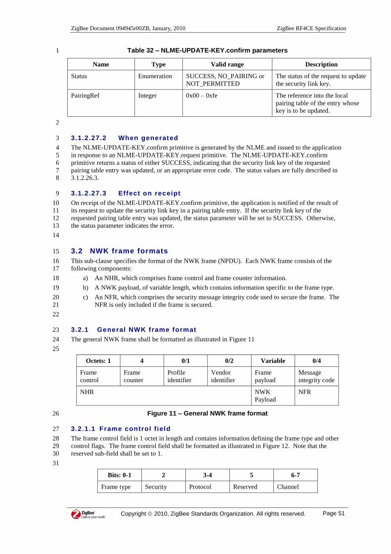
ZigBee Document 094945r00ZB, January, 2010 ZigBee RF4CE Specification
Copyright 2010, ZigBee Standards Organization. All rights reserved. Page 51
Table 32 – NLME-UPDATE-KEY.confirm parameters 1
Name Type Valid range Description
Status Enumeration SUCCESS, NO_PAIRING or
NOT_PERMITTED
The status of the request to update
the security link key.
PairingRef Integer 0x00 – 0xfe The reference into the local
pairing table of the entry whose
key is to be updated.
2
3.1.2.27.2 When generated 3
The NLME-UPDATE-KEY.confirm primitive is generated by the NLME and issued to the application 4
in response to an NLME-UPDATE-KEY.request primitive. The NLME-UPDATE-KEY.confirm 5
primitive returns a status of either SUCCESS, indicating that the security link key of the requested 6
pairing table entry was updated, or an appropriate error code. The status values are fully described in 7
3.1.2.26.3. 8
3.1.2.27.3 Effect on receipt 9
On receipt of the NLME-UPDATE-KEY.confirm primitive, the application is notified of the result of 10
its request to update the security link key in a pairing table entry. If the security link key of the 11
requested pairing table entry was updated, the status parameter will be set to SUCCESS. Otherwise, 12
the status parameter indicates the error. 13
14
3.2 NWK frame formats 15
This sub-clause specifies the format of the NWK frame (NPDU). Each NWK frame consists of the 16
following components: 17
a) An NHR, which comprises frame control and frame counter information. 18
b) A NWK payload, of variable length, which contains information specific to the frame type. 19
c) An NFR, which comprises the security message integrity code used to secure the frame. The 20
NFR is only included if the frame is secured. 21
22
3.2.1 General NWK frame format 23
The general NWK frame shall be formatted as illustrated in Figure 11 24
25
Octets: 1 4 0/1 0/2 Variable 0/4
Frame
control
Frame
counter
Profile
identifier
Vendor
identifier
Frame
payload
Message
integrity code
NHR NWK
Payload
NFR
Figure 11 – General NWK frame format 26
3.2.1.1 Frame control f ield 27
The frame control field is 1 octet in length and contains information defining the frame type and other 28
control flags. The frame control field shall be formatted as illustrated in Figure 12. Note that the 29
reserved sub-field shall be set to 1. 30
31
Bits: 0-1 2 3-4 5 6-7
Frame type Security Protocol Reserved Channel

ZigBee RF4CE Specification ZigBee Document 094945r00ZB, January, 2010
Page 52 Copyright 2010, ZigBee Standards Organization. All rights reserved.
enabled version (=1) designator
Figure 12 – Format of the frame control field 1
2
3.2.1.1.1 Frame type sub-field 3
The frame type sub-field is 2 bits in length and shall be set to one of the non reserved values listed in 4
Table 33. 5
6
Table 33 – Values of the frame type sub-field 7
Frame type value
bB1Bb B0B
Description
00 Reserved
01 Standard data frame
10 NWK command frame
11 Vendor-specific data frame
8
3.2.1.1.2 Security enabled sub-field 9
The security enabled sub-field is 1 bit in length and shall be set to 1 if the frame is protected by the 10
NWK layer. Otherwise it shall be set to 0. The message integrity code field of the NWK frame shall 11
be present only if the security enabled sub-field is set to 1. 12
3.2.1.1.3 Protocol version sub-field 13
The protocol version sub-field is 2-bits in length and shall contain the current value of 14
nwkcProtocolVersion. 15
3.2.1.1.4 Channel designator sub-field 16
The channel designator sub-field is 2-bits in length and specifies a channel designator corresponding to 17
the base channel of the device transmitting the frame. This value can be set to one of the values listed 18
in Table 34. 19
20
Table 34 – Values of the channel designator sub-field 21
Channel designator value
bB1Bb B0B
Description
00 Channel not specified
01 Channel 15
10 Channel 20
11 Channel 25
22
3.2.1.2 Frame counter f ield 23
The frame counter field is 4 octets in length and specifies a sequence identifier for the frame being 24
transported. This field is used by the NLDE to detect duplicate transmissions and for securing the 25
NWK frame. 26

ZigBee Document 094945r00ZB, January, 2010 ZigBee RF4CE Specification
Copyright 2010, ZigBee Standards Organization. All rights reserved. Page 53
3.2.1.3 Prof ile identif ier f ield 1
The profile identifier field is 1 octet in length and specifies the profile identifier of the command being 2
carried in the NWK payload field. The profile identifier field shall only be included for standard and 3
vendor-specific data frames. 4
The set of supported profile identifiers is specified in [R4] 5
3.2.1.4 Vendor ident if ier f ield 6
The vendor identifier field is 2 octets in length and specifies the vendor identifier of the command 7
being carried in the NWK payload field. The vendor identifier field shall only be included for vendor-8
specific data frames. 9
3.2.1.5 Frame payload f ield 10
The frame payload field has a variable length and contains information specific to individual frame 11
types. If the security enabled sub-field of the frame control field is set to 1, the frame payload is 12
protected. 13
3.2.1.6 Message integrity code f ield 14
The message integrity code field is 4 octets in length. The message integrity code shall be included in 15
the frame only if the security enabled sub-field of the frame control field is set to 1. If the security 16
enabled sub-field of the frame control field is set to zero, the message integrity field shall be omitted 17
from the frame. 18
3.2.2 Format of individual frame types 19
3.2.2.1 Data (standard and vendor-specif ic) f rame 20
The data frame shall be formatted as illustrated in Figure 13. 21
22
Octets: 1 4 1 0/2 Variable 0/4
Frame
control
Frame
counter
Profile
identifier
Vendor
identifier
Data payload Message
integrity code
NHR NWK
Payload
NFR
Figure 13 – Data frame format 23
The order of the fields of the data frame shall conform to the order of the general NWK frame as 24
illustrated in Figure 11. 25
3.2.2.1.1 Data frame NHR fields 26
The NHR for a data frame shall contain the frame control, frame counter and profile identifier fields. 27
In addition, a vendor-specific data frame shall also contain the vendor identifier field. 28
In the frame control field, the frame type shall contain the value that indicates either a standard or 29
vendor-specific data frame, as shown in Table 33. The security enabled sub-field shall be set according 30
to the security requirements specified by the application for each frame. The protocol version sub-field 31
shall be set according to sub-clause 3.2.1.1.3. If the node is a target and a channel designator is to be 32
included in the frame, the channel designator sub-field shall be set to the value that corresponds to the 33
channel stored in nwkBaseChannel, according to the mapping in Table 34; otherwise it shall be set to 34
0b00. 35
The frame counter field shall contain the current value of nwkFrameCounter. 36
The profile identifier field shall contain the application specified profile identifier of the data being 37
transported in the data payload field. The set of supported profile identifiers is specified in [R4] 38
The vendor identifier field shall contain the application specified vendor identifier of the data being 39
transported in the data payload field. 40

ZigBee RF4CE Specification ZigBee Document 094945r00ZB, January, 2010
Page 54 Copyright 2010, ZigBee Standards Organization. All rights reserved.
3.2.2.1.2 Data payload f ield 1
The payload of a data frame shall contain the sequence of octets that the application has requested the 2
NWK layer to transmit. 3
3.2.2.1.3 Data frame NFR f ields 4
The NFR for a data frame shall contain the message integrity code field if the security enabled sub-5
field of the frame control field is set to 1. If the security enabled sub-field of the frame control field is 6
set to zero, the message integrity field shall be omitted from the frame. 7
3.2.2.1.4 Transmitt ing the data frame via the M AC sub-layer 8
A data frame shall be transmitted via the MAC sub-layer data service. This is instigated by the NLME 9
issuing the MCPS-DATA.request primitive with the parameters listed in Table 35. 10
11
Table 35 – MCPS-DATA.request parameters for a data frame 12
Parameter Setting
SrcAddrMode 0x03 (64-bit IEEE address) if the originator is a controller and the application
requested a broadcast transmission, OR
0x02 (16-bit network address) otherwise.
DstAddrMode 0x02 (16-bit network address) if the application requested a broadcast
transmission or (the recipient is a target and the application requested a
transmission with a network address), OR
0x03 (64-bit IEEE address) if the recipient is a controller or the application
requested a transmission with an IEEE address.
DstPANId 0xffff if the recipient is a controller or the application requested a broadcast
transmission, OR
The PAN identifier of the destination device from the pairing table if the
recipient is a target.
DstAddr 0xffff if the application requested a broadcast transmission, OR
The destination IEEE address from the pairing table if the recipient is a
controller or the application requested a transmission with an IEEE address,
OR
The destination network address from the pairing table if the recipient is a
target and the application requested a transmission with a network address.
msduLength Size of the data or vendor-specific frame
msdu The data or vendor-specific frame
msduHandle Handle for this transmission
TxOptions 0b000 (no acknowledgment requested) if the application requested an
unacknowledged or broadcast transmission, OR
0b001 (acknowledgment requested) if the application requested an
acknowledged transmission.
Security Disabled.
13
3.2.2.2 NWK command frame 14
The NWK command frame shall be formatted as illustrated in Figure 14. 15
16

ZigBee Document 094945r00ZB, January, 2010 ZigBee RF4CE Specification
Copyright 2010, ZigBee Standards Organization. All rights reserved. Page 55
Octets: 1 4 1 Variable 0/4
Frame
control
Frame
counter
Command
identifier
Command
payload
Message
integrity code
NHR NWK Payload NFR
Figure 14 – NWK command frame format 1
The order of the fields of the data frame shall conform to the order of the general NWK frame as 2
illustrated in Figure 11. 3
3.2.2.2.1 NWK command frame NHR fields 4
The NHR for a NWK command frame shall contain the frame control field and the frame counter field. 5
In the frame control field, the frame type shall contain the value that indicates a NWK command frame, 6
as shown in Table 33. The protocol version sub-field shall be set according to sub-clause 3.2.1.1.3. 7
All other sub-fields shall be set according to the NWK command frame being transmitted. 8
The frame counter field shall contain the current value of nwkFrameCounter. 9
3.2.2.2.2 Command ident if ier f ield 10
The command identifier field identifies the NWK command being used. This field shall be set to one 11
of the non-reserved values listed in Table 36. 12
3.2.2.2.3 Command payload f ield 13
The command payload field contains the NWK command itself. The formats of the individual 14
commands are described in 3.3. 15
3.2.2.2.4 NWK command frame NFR f ields 16
The NFR for a NWK command frame shall contain the message integrity code field if the security 17
enabled sub-field of the frame control field is set to 1. If the security enabled sub-field of the frame 18
control field is set to zero, the message integrity field shall be omitted from the frame. 19
3.2.2.2.5 Transmitt ing the NWK command frame via the MAC sub- layer 20
A NWK command frame shall be transmitted via the MAC sub-layer data service. This is instigated by 21
the NLME issuing the MCPS-DATA.request primitive with the parameters listed in each section 22
describing the individual command frames. 23
3.3 NWK command frames 24
The command frames defined by the NWK layer are listed in Table 36. 25
26

ZigBee RF4CE Specification ZigBee Document 094945r00ZB, January, 2010
Page 56 Copyright 2010, ZigBee Standards Organization. All rights reserved.
Table 36 – NWK command frames 1
Command frame
identifier Command name Sub-clause
0x01 Discovery request 3.3.1
0x02 Discovery response 3.3.2
0x03 Pair request 3.3.3
0x04 Pair response 3.3.4
0x05 Unpair request 3.3.5
0x06 Key seed 3.3.6
0x07 Ping request 3.3.7
0x08 Ping response 3.3.8
0x09 – 0xff Reserved -
2
3.3.1 Discovery request command frame 3
The discovery request command frame allows a device to discover devices operating in its POS. 4
This command can be directed to a specific device on a specific PAN, any device on a specific PAN or 5
to any device. 6
The discovery request command frame shall be formatted as illustrated in Figure 15. 7
8
Octets:
(see 3.2.2.2) 1 1 9 3-26 1
NHR fields Command
identifier
(see Table 36)
Node
capabilities
Vendor
information
fields
(see Figure 16)
Application
information
fields
(see Figure 17)
Requested
device type
Figure 15 – Format of the discovery request command frame 9
10
Octets: 2 7
Vendor
identifier
Vendor
string
Figure 16 – Format of the vendor information fields 11
12
Octets: 1 0/15 1-3 1-7
Application
capabilities
User string Device type
list
Profile
identifier list
Figure 17 – Format of the application information fields 13
14

ZigBee Document 094945r00ZB, January, 2010 ZigBee RF4CE Specification
Copyright 2010, ZigBee Standards Organization. All rights reserved. Page 57
3.3.1.1 NHR f ields 1
The security enabled and channel designator sub-fields of the frame control field shall be set to 0 and 2
0b00, respectively. 3
3.3.1.2 Node capabi lit ies f ield 4
The node capabilities field is 1 octet in length and shall contain the capabilities of the node transmitting 5
the discovery request command frame. This field shall be set to the value of nwkcNodeCapabilities. 6
3.3.1.3 Vendor ident if ier f ield 7
The vendor identifier field is 2 octets in length and shall contain the vendor identifier of the node 8
transmitting the discovery request command frame. This field shall be set to the value of 9
nwkcVendorIdentifier. 10
The set of vendor IDs is specified in [R2] . 11
3.3.1.4 Vendor str ing f ield 12
The vendor string field is 7 octets in length and shall contain the vendor string of the node transmitting 13
the discovery request command frame. This field shall be set to the value of nwkcVendorString. 14
3.3.1.5 Applicat ion capabil it ies f ield 15
The application capabilities field is 1 octet in length and shall contain information relating to the 16
capabilities of the application of the node sending the discovery request command frame. The 17
application capabilities field shall be formatted as illustrated in Figure 18. 18
19
Bits: 0 1-2 3 4-6 7
User string
specified
Number of
supported device
types
Reserved Number of
supported
profiles
Reserved
Figure 18 – Format of the application capabilities field 20
3.3.1.5.1 User string specif ied sub-field 21
The user string specified sub-field is 1 bit in length and shall be set to one if a user string is to be 22
included in the frame. Otherwise, it shall be set to zero. The user string field shall be included in the 23
frame only if the user string specified sub-field is set to one. 24
3.3.1.5.2 Number of supported device types sub -field 25
The number of supported device types sub-field is 2-bits in length and shall contain the number of 26
device types supported by the application of the node sending the discovery request command frame. 27
This sub-field specifies the number of device types contained in the device type list field and shall be 28
greater than zero. 29
3.3.1.5.3 Number of supported profi les sub-field 30
The number of supported profiles sub-field is 3-bits in length and shall contain the number of profiles 31
disclosed as supported by the application of the node sending the discovery request command frame. 32
This sub-field specifies the number of profile identifiers contained in the profile identifier list field and 33
shall be greater than zero. 34
3.3.1.6 User string f ield 35
The user string field is 15 octets in length and shall contain the user specified identification string for 36
the node sending the discovery request command frame. This field shall be included in the frame only 37
if the user string specified sub-field of the application capabilities field is set to one. 38

ZigBee RF4CE Specification ZigBee Document 094945r00ZB, January, 2010
Page 58 Copyright 2010, ZigBee Standards Organization. All rights reserved.
3.3.1.7 Device type l ist f ield 1
The device type list field is 1-3 octets in length and shall contain the list of device types supported by 2
the node sending the discovery request command frame. The length of this field shall be specified by 3
the number of supported device types sub-field of the application capabilities field. 4
The set of supported device types is specified in [R3] . 5
3.3.1.8 Prof ile identif ier l ist f ield 6
The profile identifier list field is 1-7 octets in length and shall contain the list of profile identifiers 7
disclosed as supported by the node sending the discovery request command frame. The length of this 8
field shall be specified by the number of supported profiles sub-field of the application capabilities 9
field. 10
The set of supported profile identifiers is specified in [R4] 11
3.3.1.9 Requested device type f ield 12
The requested device type field is 1 octet in length and shall contain the type of device the application 13
is attempting to discover. 14
If this value is set to 0xff, all devices that hear the command could respond with discovery response 15
frames. Alternatively, if this value is set to a value other than 0xff, all devices that support that device 16
type could respond with discovery response command frames. 17
3.3.1.10 Transmitt ing the frame via the M AC sub -layer 18
The discovery request command frame shall be transmitted via the MAC sub-layer data service. This 19
is instigated by the NLME issuing the MCPS-DATA.request primitive with the parameters listed in 20
Table 37. 21
22
Table 37 – MCPS-DATA.request parameters for a discovery request command frame 23
Parameter Setting
SrcAddrMode 0x03 (64-bit IEEE address)
DstAddrMode 0x02 (16-bit network address)
DstPANId 0xffff or the PAN ID of the intended recipient
DstAddr 0xffff or the network address of the intended recipient
msduLength Size of the discovery request command
msdu The discovery request command
msduHandle Handle for this transmission
TxOptions 0b000
Security This frame shall be transmitted without MAC security
24
3.3.2 Discovery response command frame 25
The discovery response command frame allows a device that receives a discovery request command 26
frame to respond with information that will allow the originating device to make a selection for pairing. 27
This command is unicast back to the originator of the discovery request command frame. 28
The discovery response command frame shall be formatted as illustrated in Figure 19. 29
30

ZigBee Document 094945r00ZB, January, 2010 ZigBee RF4CE Specification
Copyright 2010, ZigBee Standards Organization. All rights reserved. Page 59
Octets:
(see 3.2.2.2) 1 1 1 9 3-26 1
NHR fields Command
identifier
(see Table 36)
Status Node
capabilities
Vendor
information
fields
(see Figure
16)
Application
information
fields
(see Figure
17)
Discovery
request LQI
Figure 19 – Format of the discovery response command frame 1
2
3.3.2.1 NHR f ields 3
The security enabled and channel designator sub-fields of the frame control field shall be set to 0 and 4
0b00, respectively. 5
3.3.2.2 Status f ield 6
The status field is 1 octet in length and shall contain the result of the discovery attempt as reported by 7
the device transmitting the discovery response command frame. 8
3.3.2.3 Node capabi lit ies f ield 9
The node capabilities field is 1 octet in length and shall contain the capabilities of the node transmitting 10
the discovery response command frame. This value shall be set to the value of nwkcNodeCapabilities. 11
3.3.2.4 Vendor ident if ier f ield 12
The vendor identifier field is 2 octets in length and shall contain the vendor identifier of the node 13
transmitting the discovery response command frame. This field shall be set to the value of 14
nwkcVendorIdentifier. 15
The set of vendor IDs is specified in [R2] . 16
3.3.2.5 Vendor str ing f ield 17
The vendor string field is 7 octets in length and shall contain the vendor string of the node transmitting 18
the discovery response command frame. This field shall be set to the value of nwkcVendorString. 19
3.3.2.6 Applicat ion capabil it ies f ield 20
The application capabilities field is 1 octet in length and shall contain information relating to the 21
capabilities of the application of the node sending the discovery response command frame. The 22
application capabilities field shall be formatted as illustrated in Figure 18. 23
3.3.2.6.1 User string specif ied sub-field 24
The user string specified sub-field is 1 bit in length and shall be set to one if a user string is to be 25
included in the frame. Otherwise, it shall be set to zero. The user string field shall be included in the 26
frame only if the user string specified sub-field is set to one. 27
3.3.2.6.2 Number of supported device types sub -field 28
The number of supported device types sub-field is 2-bits in length and shall contain the number of 29
device types supported by the application of the node sending the discovery response command frame. 30
This sub-field specifies the number of device types contained in the device type list field and shall be 31
greater than zero. 32
3.3.2.6.3 Number of supported profi les sub-field 33
The number of supported profiles sub-field is 3-bits in length and shall contain the number of profiles 34
supported by the application of the node sending the discovery response command frame. This sub-35
field specifies the number of profile identifiers contained in the profile identifier list field and shall be 36
greater than zero. 37

ZigBee RF4CE Specification ZigBee Document 094945r00ZB, January, 2010
Page 60 Copyright 2010, ZigBee Standards Organization. All rights reserved.
3.3.2.7 User string f ield 1
The user string field is 15 octets in length and shall contain the user specified identification string for 2
the node sending the discovery response command frame. This field shall be included in the frame 3
only if the user string specified sub-field of the application capabilities field is set to one. 4
3.3.2.8 Device type l ist f ield 5
The device type list field is 1-3 octets in length and shall contain the list of device types supported by 6
the node sending the discovery response command frame. The length of this field shall be specified by 7
the number of supported device types sub-field of the application capabilities field. 8
The set of supported device types is specified in [R3] . 9
3.3.2.9 Prof ile identif ier l ist f ield 10
The profile identifier list field is 1-7 octets in length and shall contain the list of profile identifiers 11
supported by the node sending the discovery response command frame. The length of this field shall 12
be specified by the number of supported profiles sub-field of the application capabilities field. 13
The set of supported profile identifiers is specified in [R4] 14
3.3.2.10 Discovery request LQI f ield 15
The discovery request LQI field is 1 octet in length and shall contain the LQI measured by the PHY on 16
reception of the original discovery request command frame and reported by the MAC sub-layer. 17
Note that in normal discovery mode, the LQI of the received discovery request command frame is 18
passed to and from the application via the NLME-DISCOVERY.indication and NLME-19
DISCOVERY.response primitives, respectively, so that the NLME does not need to store the LQI 20
value. Conversely, in auto discovery mode, the application is not involved and the NLME constructs 21
this field as described. 22
3.3.2.11 Transmitt ing the frame via the M AC sub-layer 23
The discovery response command frame shall be transmitted via the MAC sub-layer data service. This 24
is instigated by the NLME issuing the MCPS-DATA.request primitive with the parameters listed in 25
Table 38. 26
27
Table 38 – MCPS-DATA.request parameters for a discovery response command frame 28
Parameter Setting
SrcAddrMode 0x03 (64-bit IEEE address)
DstAddrMode 0x03 (64-bit IEEE address)
DstPANId 0xffff
DstAddr IEEE address of originator
msduLength Size of the discovery response command
msdu The discovery response command
msduHandle Handle for this transmission
TxOptions 0b001 (acknowledgment requested)
Security This frame shall be transmitted without MAC security
29
3.3.3 Pair request command frame 30
The pair request command frame allows a device to request to pair with another device. Usually, this 31
would be preceded by a discovery operation. 32
This command is unicast to the node to which a pairing link is required. 33

ZigBee Document 094945r00ZB, January, 2010 ZigBee RF4CE Specification
Copyright 2010, ZigBee Standards Organization. All rights reserved. Page 61
The pair request command frame shall be formatted as illustrated in Figure 20. 1
2
Octets:
(see 3.2.2.2) 1 2 1 9 3-26 1
NHR fields Command
identifier
(see Table 36)
Network
address
Node
capabilities
Vendor
information
fields
(see Figure
16)
Application
information
fields
(see Figure
17)
Key
exchange
transfer count
Figure 20 – Format of the pair request command frame 3
3.3.3.1 NHR f ields 4
The security enabled sub-field of the frame control field shall be set to 0. The channel designator sub-5
field of the frame control field shall contain the value corresponding to nwkBaseChannel if the node 6
sending the pair request command frame is a target. Otherwise, this field shall be set to 0b00. 7
3.3.3.2 Network address f ield 8
The network address field is 2 octets in length and shall contain the network address 9
(macShortAddress) of the node sending the pair request command frame if it is a target. Otherwise, 10
this field shall be set to 0xfffe. 11
3.3.3.3 Node capabi lit ies f ield 12
The node capabilities field is 1 octet in length and shall contain the capabilities of the node transmitting 13
the pair request command frame. This field shall be set to the value of nwkcNodeCapabilities. 14
3.3.3.4 Vendor ident if ier f ield 15
The vendor identifier field is 2 octets in length and shall contain the vendor identifier of the node 16
transmitting the pair request command frame. This field shall be set to the value of 17
nwkcVendorIdentifier. 18
The set of vendor IDs is specified in [R2] . 19
3.3.3.5 Vendor str ing f ield 20
The vendor string field is 7 octets in length and shall contain the vendor string of the node transmitting 21
the pair request command frame. This field shall be set to the value of nwkcVendorString. 22
3.3.3.6 Applicat ion capabil it ies f ield 23
The application capabilities field is 1 octet in length and shall contain information relating to the 24
capabilities of the application of the node sending the pair request command frame. The application 25
capabilities field shall be supplied by the application and shall be formatted as illustrated in Figure 18. 26
3.3.3.6.1 User string specif ied sub-field 27
The user string specified sub-field is 1 bit in length and shall be set to one if a user string is to be 28
included in the frame. Otherwise, it shall be set to zero. The user string field shall be included in the 29
frame only if the user string specified sub-field is set to one. 30
3.3.3.6.2 Number of supported device types sub -field 31
The number of supported device types sub-field is 2-bits in length and shall contain the number of 32
device types supported by the application of the node sending the pair request command frame. This 33
sub-field specifies the number of device types contained in the device type list field and shall be greater 34
than zero. 35
3.3.3.6.3 Number of supported profi les sub-field 36
The number of supported profiles sub-field is 3-bits in length and shall contain the number of profiles 37
supported by the application of the node sending the pair request command frame. This sub-field 38

ZigBee RF4CE Specification ZigBee Document 094945r00ZB, January, 2010
Page 62 Copyright 2010, ZigBee Standards Organization. All rights reserved.
specifies the number of profile identifiers contained in the profile identifier list field and shall be 1
greater than zero. 2
3.3.3.7 User string f ield 3
The user string field is 15 octets in length and shall contain the user specified identification string for 4
the node sending the pair request command frame. This field shall be included in the frame only if the 5
user string specified sub-field of the application capabilities field is set to one and shall be set to the 6
value of nwkUserString. 7
3.3.3.8 Device type l ist f ield 8
The device type list field is 1-3 octets in length and shall contain the list of device types supported by 9
the node sending the pair request command frame. The length of this field shall be specified by the 10
number of supported device types sub-field of the application capabilities field. The device type list 11
field shall be supplied by the application. 12
The set of supported device types is specified in [R3] . 13
3.3.3.9 Prof ile identif ier l ist f ield 14
The profile identifier list field is 1-7 octets in length and shall contain the list of profile identifiers 15
supported by the node sending the pair request command frame. The length of this field shall be 16
specified by the number of supported profiles sub-field of the application capabilities field. The profile 17
identifier list field shall be supplied by the application. 18
The set of supported profile identifiers is specified in [R4] 19
3.3.3.10 Key exchange transfer count f ield 20
The key exchange transfer count field is 1 octet in length and shall contain the number of transfers the 21
originator wishes to use to exchange a security link key for the pairing link. This value shall be set in 22
the range 0x00 – 0xff. 23
If security is not supported by the originator, this field shall be set to zero. 24
3.3.3.11 Transmitt ing the frame via the M AC sub -layer 25
If the pair request command frame is to be transmitted by a controller node, it shall first set macPANId 26
to 0xffff. 27
The pair request command frame shall be transmitted via the MAC sub-layer data service. This is 28
instigated by the NLME issuing the MCPS-DATA.request primitive with the parameters listed in Table 29
39. 30
31
Table 39 – MCPS-DATA.request parameters for a pair request command frame 32
Parameter Setting
SrcAddrMode 0x03 (64-bit IEEE address)
DstAddrMode 0x03 (64-bit IEEE address)
DstPANId PAN ID of the intended recipient
DstAddr IEEE address of the intended recipient of this command
msduLength Size of the pair request command
msdu The pair request command
msduHandle Handle for this transmission
TxOptions 0b001 (acknowledgement requested)
Security This frame shall be transmitted without MAC security
33

ZigBee Document 094945r00ZB, January, 2010 ZigBee RF4CE Specification
Copyright 2010, ZigBee Standards Organization. All rights reserved. Page 63
3.3.4 Pair response command frame 1
The pair response command frame allows a device to respond to a pair request and pass information 2
relevant to the pairing link back to the originator. 3
This command is unicast back to the originator of the pair request command frame. 4
The pair response command frame shall be formatted as illustrated in Figure 21. 5
6
Octets: (see 3.2.2.2)
1 1 2 2 1 9 3-26
NHR fields Command
identifier
(see Table
36)
Status Allocated
network
address
Network
address
Node
capabilities
Vendor
information
fields
(see Figure
16)
Application
information
fields
(see Figure
17)
Figure 21 – Format of the pair response command frame 7
3.3.4.1 NHR f ields 8
The security enabled sub-field of the frame control field shall be set to 0. The channel designator sub-9
field of the frame control field shall contain the value corresponding to nwkBaseChannel. 10
3.3.4.2 Status f ield 11
The status field is 1 octet in length and shall contain the result of the pairing attempt as reported by the 12
device transmitting the pair response command frame. 13
3.3.4.3 Al located network address f ield 14
The allocated network address field is 2 octets in length and shall contain a network address allocated 15
by the node sending the pair response command frame if it is a target and the originator of the pair 16
request command frame is a controller. Otherwise, this field shall be set to 0xfffe. 17
3.3.4.4 Network address f ie ld 18
The network address field is 2 octets in length and shall contain the network address of the node 19
sending the pair response command frame. 20
3.3.4.5 Node capabi lit ies f ield 21
The node capabilities field is 1 octet in length and shall contain the capabilities of the node transmitting 22
the pair response command frame. This value shall be set to the value of nwkcNodeCapabilities. 23
3.3.4.6 Vendor ident if ier f ield 24
The vendor identifier field is 2 octets in length and shall contain the vendor identifier of the node 25
transmitting the pair response command frame. This field shall be set to the value of 26
nwkcVendorIdentifier. 27
The set of vendor IDs is specified in [R2] . 28
3.3.4.7 Vendor str ing f ield 29
The vendor string field is 7 octets in length and shall contain the vendor string of the node transmitting 30
the pair response command frame. This field shall be set to the value of nwkcVendorString. 31
3.3.4.8 Applicat ion capabil it ies f ield 32
The application capabilities field is 1 octet in length and shall contain information relating to the 33
capabilities of the application of the node sending the pair response command frame. The application 34
capabilities field shall supplied by the application and shall be formatted as illustrated in Figure 18. 35

ZigBee RF4CE Specification ZigBee Document 094945r00ZB, January, 2010
Page 64 Copyright 2010, ZigBee Standards Organization. All rights reserved.
3.3.4.8.1 User string specif ied sub-field 1
The user string specified sub-field is 1 bit in length and shall be set to one if a user string is to be 2
included in the frame. Otherwise, it shall be set to zero. The user string field shall be included in the 3
frame only if the user string specified sub-field is set to one. 4
3.3.4.8.2 Number of supported device types sub -field 5
The number of supported device types sub-field is 2-bits in length and shall contain the number of 6
device types supported by the application of the node sending the pair response command frame. This 7
sub-field specifies the number of device types contained in the device type list field and shall be greater 8
than zero. 9
3.3.4.8.3 Number of supported profi les sub-field 10
The number of supported profiles sub-field is 3-bits in length and shall contain the number of profiles 11
supported by the application of the node sending the pair response command frame. This sub-field 12
specifies the number of profile identifiers contained in the profile identifier list field and shall be 13
greater than zero. 14
3.3.4.9 User string f ield 15
The user string field is 15 octets in length and shall contain the user specified identification string for 16
the node sending the pair response command frame. This field shall be included in the frame only if 17
the user string specified sub-field of the application capabilities field is set to one and shall be set to the 18
value of nwkUserString. 19
3.3.4.10 Device type l ist f ield 20
The device type list field is 1-3 octets in length and shall contain the list of device types supported by 21
the node sending the pair response command frame. The length of this field shall be specified by the 22
number of supported device types sub-field of the application capabilities field. The device type list 23
field shall be supplied by the application. 24
The set of supported device types is specified in [R3] . 25
3.3.4.11 Prof ile identif ier l ist f ield 26
The profile identifier list field is 1-7 octets in length and shall contain the list of profile identifiers 27
supported by the node sending the pair response command frame. The length of this field shall be 28
specified by the number of supported profiles sub-field of the application capabilities field. The profile 29
identifier list field shall be supplied by the application. 30
The set of supported profile identifiers is specified in [R4] 31
3.3.4.12 Transmitt ing the frame via the M AC sub -layer 32
The pair response command frame shall only be transmitted by a target node. 33
The pair response command frame shall be transmitted via the MAC sub-layer data service. This is 34
instigated by the NLME issuing the MCPS-DATA.request primitive with the parameters listed in Table 35
40. 36
37

ZigBee Document 094945r00ZB, January, 2010 ZigBee RF4CE Specification
Copyright 2010, ZigBee Standards Organization. All rights reserved. Page 65
Table 40 – MCPS-DATA.request parameters for a pair response command frame 1
Parameter Setting
SrcAddrMode 0x03 (64-bit IEEE address)
DstAddrMode 0x03 (64-bit IEEE address)
DstPANId 0xffff if the intended recipient is a controller or the PAN ID of the
intended recipient otherwise.
DstAddr IEEE address of intended recipient of this command
msduLength Size of the pair response command
msdu The pair response command
msduHandle Handle for this transmission
TxOptions 0b001 (acknowledgment requested)
Security This frame shall be transmitted without MAC security
2
3.3.5 Unpair request command frame 3
The unpair request command frame allows a device to request to remove a pairing link on a remote 4
device. 5
This command is unicast to the node on which the pairing link is to be removed and shall be sent 6
securely if a link key exists for the corresponding pairing link. Otherwise, this command shall be sent 7
without security. 8
The unpair request command frame shall be formatted as illustrated in Figure 22. 9
10
Octets: (see 3.2.2.2)
1 0/4
NHR fields Command
identifier (see Table 36)
NFR fields
Figure 22 – Format of the unpair request command frame 11
3.3.5.1 NHR f ields 12
The security enabled sub-field of the frame control shall be set to 1 if a link key exists for the 13
corresponding pairing link or to 0 if a link key does not exist for the corresponding pairing link. The 14
channel designator sub-field of the frame control field shall be set to 0b00. 15
3.3.5.2 NFR fields 16
The message integrity code field shall be included in the frame if a link key exists for the pairing link 17
that is to be removed. Otherwise, the message integrity code field shall not be included in the frame. 18
3.3.5.3 Transmitt ing the frame via the M AC sub -layer 19
The unpair request command frame shall be transmitted via the MAC sub-layer data service. This is 20
instigated by the NLME issuing the MCPS-DATA.request primitive with the parameters listed in Table 21
41. 22
23

ZigBee RF4CE Specification ZigBee Document 094945r00ZB, January, 2010
Page 66 Copyright 2010, ZigBee Standards Organization. All rights reserved.
Table 41 – MCPS-DATA.request parameters for an unpair request command frame 1
Parameter Setting
SrcAddrMode 0x03 (64-bit IEEE address)
DstAddrMode 0x03 (64-bit IEEE address)
DstPANId PAN ID from the pairing table if the intended recipient is a target
or 0xffff if the intended recipient is a controller.
DstAddr IEEE address of the intended recipient
msduLength Size of the unpair request command
msdu The unpair request command
msduHandle Handle for this transmission
TxOptions 0b001 (acknowledgement requested)
Security This frame shall be transmitted without MAC security
2
3.3.6 Key seed command frame 3
The key seed command frame allows a device to exchange security key seed values with a remote 4
device in order to generate a security link key. 5
This command is unicast to a specific device and shall be sent with a transmit power of, at most, 6
nwkcMaxSecCmdTxPower. 7
The key seed command frame shall be formatted as illustrated in Figure 23. 8
9
Octets: (see 3.2.2.2)
1 1 80
NHR fields Command
identifier (see Table 36)
Seed
sequence
number
Seed data
Figure 23 – Format of the key seed command frame 10
3.3.6.1 NHR f ields 11
The security enabled and channel designator sub-fields of the frame control field shall be set to 0 and 12
0b00, respectively. 13
3.3.6.2 Seed sequence number f ield 14
The seed sequence number field is 1 octet in length and shall contain the sequence number of the seed 15
contained in the seed data field. 16
3.3.6.3 Seed data f ield 17
The seed data field is 80 octets in length and shall contain the data for the seed identified by the seed 18
sequence number field. 19
3.3.6.4 Transmitt ing the frame via the M AC sub -layer 20
The key seed command frame shall be transmitted via the MAC sub-layer data service. This is 21
instigated by the NLME issuing the MCPS-DATA.request primitive with the parameters listed in Table 22
42. 23
24

ZigBee Document 094945r00ZB, January, 2010 ZigBee RF4CE Specification
Copyright 2010, ZigBee Standards Organization. All rights reserved. Page 67
Table 42 – MCPS-DATA.request parameters for an key seed command frame 1
Parameter Setting
SrcAddrMode 0x03 (64-bit IEEE address)
DstAddrMode 0x03 (64-bit IEEE address)
DstPANId 0xffff
DstAddr IEEE address of the intended recipient
msduLength Size of the key seed command
msdu The key seed command
msduHandle Handle for this transmission
TxOptions 0b001 (acknowledgement requested)
Security This frame shall be transmitted without MAC security
2
3.3.7 Ping request command frame 3
The ping request command frame allows a device to send a ping command frame to another device and 4
get a response. 5
This command is unicast to a specific device on a specific PAN and shall always be sent securely. 6
The ping request command frame shall be formatted as illustrated in Figure 24. 7
8
Octets: (see 3.2.2.2)
1 1 Variable 4
NHR fields Command
identifier (see Table 36)
Ping options Ping payload NFR
fields
Figure 24 – Format of the ping request command frame 9
3.3.7.1 NHR f ields 10
The security enabled and channel designator sub-fields of the frame control field shall be set to 1 and 11
0b00, respectively. 12
3.3.7.2 Ping options f ield 13
The ping options field is 1 octet in length and shall contain options defined by the procedure in which 14
the ping request command is used. 15
3.3.7.3 Ping payload f ield 16
The ping payload field has a variable length and shall contain a payload defined by the procedure in 17
which the ping request command is used. 18
3.3.7.4 NFR fields 19
The message integrity code field shall always be included in the frame, generated using the security 20
link key of the recipient. 21
3.3.7.5 Transmitt ing the frame via the M AC sub -layer 22
The ping request command frame shall be transmitted via the MAC sub-layer data service. This is 23
instigated by the NLME issuing the MCPS-DATA.request primitive with the parameters listed in Table 24
42. 25
26

ZigBee RF4CE Specification ZigBee Document 094945r00ZB, January, 2010
Page 68 Copyright 2010, ZigBee Standards Organization. All rights reserved.
Table 43 – MCPS-DATA.request parameters for a ping request command frame 1
Parameter Setting
SrcAddrMode 0x03 (64-bit IEEE address)
DstAddrMode 0x03 (64-bit IEEE address)
DstPANId 0xffff
DstAddr IEEE address of the intended recipient
msduLength Size of the ping request command
msdu The ping request command
msduHandle Handle for this transmission
TxOptions 0b001 (acknowledgement requested)
Security This frame shall be transmitted without MAC security
2
3.3.8 Ping response command frame 3
The ping response command frame allows a device to respond to a ping request command frame from 4
another device. 5
This command is unicast back to the originator of the ping request command frame and shall always be 6
sent securely. 7
The ping response command frame shall be formatted as illustrated in Figure 25. 8
9
Octets: (see 3.2.2.2)
1 1 Variable 4
NHR fields Command
identifier (see Table 36)
Ping options Ping payload NFR
fields
Figure 25 – Format of the ping response command frame 10
3.3.8.1 NHR f ields 11
The security enabled and channel designator sub-fields of the frame control field shall be set to 1 and 12
0b00, respectively. 13
3.3.8.2 Ping options f ield 14
The ping options field is 1 octet in length and shall contain the value of the ping options field of the 15
ping request command frame. 16
3.3.8.3 Ping payload f ield 17
The ping payload field has a variable length and shall contain the value of the ping payload field of the 18
ping request command frame. 19
3.3.8.4 NFR fields 20
The message integrity code field shall always be included in the frame, generated using the security 21
link key of the recipient. 22
3.3.8.5 Transmitt ing the frame via the M AC sub-layer 23
The ping response command frame shall be transmitted via the MAC sub-layer data service. This is 24
instigated by the NLME issuing the MCPS-DATA.request primitive with the parameters listed in Table 25
44. 26

ZigBee Document 094945r00ZB, January, 2010 ZigBee RF4CE Specification
Copyright 2010, ZigBee Standards Organization. All rights reserved. Page 69
1
Table 44 – MCPS-DATA.request parameters for a ping response command frame 2
Parameter Setting
SrcAddrMode 0x03 (64-bit IEEE address)
DstAddrMode 0x03 (64-bit IEEE address)
DstPANId 0xffff
DstAddr IEEE address of the originator of the ping request
msduLength Size of the ping response command
msdu The ping response command
msduHandle Handle for this transmission
TxOptions 0b001 (acknowledgement requested)
Security This frame shall be transmitted without MAC security
3
4
3.4 NWK enumerations, constants and attributes 5
3.4.1 NWK enumerat ions 6
This sub-clause explains the meaning of the enumerations used in this specification. Table 45 shows a 7
description of the NWK enumeration values. In some cases, primitives will carry results from the 8
MAC sub-layer containing other enumeration values; these values are defined in [R1] . 9
10
Table 45 – NWK enumerations description 11
Value Enumeration Description
0x00 SUCCESS The requested operation was completed
successfully.
0xb0 NO_ORG_CAPACITY A pairing link cannot be established since the
originator node has reached its maximum
number of entries in its pairing table.
0xb1 NO_REC_CAPACITY A pairing link cannot be established since the
recipient node has reached its maximum
number of entries in its pairing table.
0xb2 NO_PAIRING A pairing table entry could not be found that
corresponds to the supplied pairing
reference.
0xb3 NO_RESPONSE A response frame was not received within
nwkResponseWaitTime or an
acknowledgement for a data frame was not
received within nwkcMaxDutyCycle.
0xb4 NOT_PERMITTED A pairing request was denied by the recipient
node or an attempt to update a security link
key was not possible due to one or more
nodes not supporting security.

ZigBee RF4CE Specification ZigBee Document 094945r00ZB, January, 2010
Page 70 Copyright 2010, ZigBee Standards Organization. All rights reserved.
Value Enumeration Description
0xb5 DUPLICATE_PAIRING A duplicate pairing table entry was detected
following the receipt of a pairing request
command frame.
0xb6 FRAME_COUNTER_EXPIRED The frame counter has reached its maximum
value.
0xb7 DISCOVERY_ERROR Too many unique matched discovery request
or valid response command frames were
received than requested.
0xb8 DISCOVERY_TIMEOUT No discovery request or response command
frames were received during discovery.
0xb9 SECURITY_TIMEOUT The security link key exchange or recovery
procedure did not complete within the
required time.
0xba SECURITY_FAILURE A security link key was not successfully
established between both ends of a pairing
link.
0xe8 INVALID_PARAMETER A parameter in the primitive is either not
supported or is out of the valid range.
0xf4 UNSUPPORTED_ATTRIBUTE A SET/GET request was issued with the
identifier of a NIB attribute that is not
supported.
0xf9 INVALID_INDEX An attempt to write to a NIB attribute that is
in a table failed because the specified table
index was out of range.
1
3.4.2 NWK constants 2
The constants that define the characteristics of the NWK layer are presented in Table 46. 3
Table 46 – NWK layer constants 4
Constant Description Value
nwkcChannelMask The channel mask to use in all
scanning operations.
See Table 47.
nwkcFrameCounterWindow The amount that needs to be
added to the frame counter if
a device is reset.
1024
nwkcMACBeaconPayloadLength The length, in octets, of the
MAC beacon payload field, as
used by the ZigBee RF4CE
protocol.
2
nwkcMaxNodeDescListSize The maximum number of
entries supported in the node
descriptors list generated
through the discovery
process.
Implementation-specific but ≥
nwkcMinNodeDescListSize
nwkcMaxDutyCycle The maximum duty cycle in
MAC symbols, permitted for
a power saving device.
62500 (1s)

ZigBee Document 094945r00ZB, January, 2010 ZigBee RF4CE Specification
Copyright 2010, ZigBee Standards Organization. All rights reserved. Page 71
Constant Description Value
nwkcMaxKeySeedWaitTime The maximum time, in MAC
symbols, to wait for each
security link key seed
exchange.
3750 (60ms)
(see Equation 1)
nwkcMaxPairingTableEntries The maximum number of
entries supported in the
pairing table.
Implementation-specific
nwkcMaxSecCmdTxPower The maximum acceptable
power, in dBm, at which key
seed command frames should
be sent.
-15
nwkcMinActivePeriod The minimum receiver on
time, in MAC symbols,
permitted for a power saving
device.
1050 (16.8ms)
(see Equation 2)
nwkcMinControllerPairingTableSize The minimum number of
pairing table entries that a
controller device shall
support.
1
nwkcMinNodeDescListSize The minimum number of
entries that must be supported
in the node descriptor list
generated through the
discovery process.
3
nwkcMinNWKHeaderOverhead The minimum overhead the
NWK layer adds to an
application payload
5
nwkcMinTargetPairingTableSize The minimum number of
pairing table entries that a
target device shall support.
5
nwkcNodeCapabilities The capabilities of this node. Implementation-specific
according to the format
illustrated in Figure 26.
nwkcProtocolIdentifier The identifier of the NWK
layer protocol being used by
this device.
0xce
nwkcProtocolVersion The version of the ZigBee
RF4CE protocol implemented
on this device.
0b01
nwkcVendorIdentifier The manufacturer-specific
vendor identifier for this
node.
Vendor ID corresponding to
the device manufacturer
nwkcVendorString The manufacturer-specific
identification string for this
node.
Implementation-specific
format of 7 octets.
1
3.4.2.1 Maximum key exchange wait durat ion 2
The nwkcMaxKeySeedWaitTime constant shall be computed according to Equation 1. 3

ZigBee RF4CE Specification ZigBee Document 094945r00ZB, January, 2010
Page 72 Copyright 2010, ZigBee Standards Organization. All rights reserved.
1
Equation 1 – Computation for nwkcMaxKeySeedWaitTime 2
nwkcMaxKeySeedWaitTime = Nat*(TBbo1 B + TBccaB + TBcmdB + TBack B + Tspt) 3
4
Where: 5
6
7
3.4.2.2 Channel mask 8
The nwkcChannelMask constant shall contain the value illustrated in Table 47. 9
10
Table 47 – The value of the nwkcChannelMask constant 11
bB26 B bB25 B b B24 B
0 1 0
bB23B bB22B b B21B bB20B bB19 B bB18 B bB17 B b B16 B
0 0 0 1 0 0 0 0
bB15B bB14B b B13B bB12B bB11 B bB10 B bB9B b B8B
1 0 0 0 0 0 0 0
bB7B bB6B b B5B bB4B bB3B bB2B bB1B b B0B
0 0 0 0 0 0 0 0
12
3.4.2.3 Minimum act ive period 13
The nwkcMinActivePeriod constant shall be computed according to Equation 2. 14
15
Equation 2 – Computation for nwkcMinActivePeriod 16
nwkcMinActivePeriod = NBchB * ( TBcmdB + TBack B + TBchB + TBbo1 B + TBccaB + Tspt) + TBcmdB 17
18
Where: 19
NBchB Is equal to the number of channels being utilized (3).
TBcmdB Is equal to the time to receive a message that will wake up the node,
assuming 16-bit addressing with security. (78 symbols)
TBack B Is equal to macAckWaitDuration (54 symbols)
TBch B Is equal to the time to switch channels (12 symbols)
Nat A factor recognizing that multiple key seed transmission attempts may be
necessary (3). Note that this is not the same as the maximum number of
transmission attempts.
TBbo1 B Is the worst case 1 P
stP CSMA backoff period (140 symbols)
TBcca B Is the time to perform a clear channel assessment (8 symbols)
TBcmdB Is equal to the time to transmit a key seed command frame, assuming 64-
bit addressing and no security (236 symbols)
TBack B Is equal to macAckWaitDuration (54 symbols)
Tspt Is the stack processing time (812 symbols)

ZigBee Document 094945r00ZB, January, 2010 ZigBee RF4CE Specification
Copyright 2010, ZigBee Standards Organization. All rights reserved. Page 73
TBbo1B Is the worst case 1 P
stP CSMA backoff period (140 symbols)
TBccaB Is the time to perform a clear channel assessment (8 symbols)
Tspt Is the stack processing time (32 symbols)
1
3.4.2.4 Node capabi lit ies 2
The nwkcNodeCapabilities constant shall be formatted as illustrated in Figure 26. 3
4
Bits: 0 1 2 3 4-7
Node type Power source Security capable Channel
normalization
capable
Reserved
Figure 26 – Format of the nwkcNodeCapabilities constant 5
6
The node type sub-field is 1-bit in length and shall be set to one if the node is a target node. Otherwise, 7
the node type sub-field shall be set to zero indicating a controller node. 8
The power source sub-field is 1-bit in length and shall be set to one if the node is receiving power from 9
the alternating current mains. Otherwise, the power source sub-field shall be set to zero. 10
The security capable sub-field is 1-bit in length and shall be set to one if the node is capable of sending 11
and receiving cryptographically protected frames, as specified in [R1]. Otherwise, the security capable 12
sub-field shall be set to zero. 13
The channel normalization sub-field is 1-bit in length and shall be set to one if the node will react to a 14
channel change request through the channel designator sub-field of the frame control field. Otherwise, 15
the channel normalization sub-field shall be set to zero. 16
3.4.3 NIB attributes 17
The NIB comprises attributes required to manage the NWK layer of a device. The attributes contained 18
in the NIB are presented in Table 48. 19
20
Table 48 – NIB attributes 21
Attribute Identifier Type Range Description Default
nwkActivePeriod 0x60 Integer nwkcMin-
ActivePeriod –
nwkDutyCycle
The active period
of a device in
MAC symbols.
0x00041a(16.8
ms)
nwkBaseChannel 0x61 Integer 15, 20 or 25 The logical
channel that was
chosen during
device
initialization.
15
nwkDiscoveryLQI-
Threshold
0x62 Integer 0x00 – 0xff The LQI
threshold below
which discovery
requests will be
rejected.
0xff

ZigBee RF4CE Specification ZigBee Document 094945r00ZB, January, 2010
Page 74 Copyright 2010, ZigBee Standards Organization. All rights reserved.
Attribute Identifier Type Range Description Default
nwkDiscovery-
RepetitionInterval
0x63 Integer 0x000000 –
0xffffff
The interval, in
MAC symbols, at
which discovery
attempts are made
on all channels.
0x0030d4
(200ms)
nwkDutyCycle 0x64 Integer 0x000000,
nwkcMinActive
Period –
nwkcMax-
DutyCycle
The duty cycle of
a device in MAC
symbols. A value
of 0x000000
indicates the
device is not
using RF4CE
power saving and
the application
must provide this
functionality
directly.
0x000000
nwkFrameCounter 0x65 Integer 0x00000001 –
0xffffffff
The frame
counter added to
the transmitted
NPDU.
0x00000001
nwkIndicateDiscovery-
Requests
0x66 Boolean TRUE or
FALSE
Indicates whether
the NLME
indicates the
reception of
discovery request
command frames
to the application.
TRUE indicates
that the NLME
notifies the
application.
FALSE
nwkInPowerSave 0x67 Boolean TRUE or
FALSE
The power save
mode of the node.
TRUE indicates
that the device is
operating in
power save mode.
FALSE
nwkPairingTable 0x68 List of
pairing
table
entries
(see Table
49)
Variable The pairing table
managed by the
device.
Empty list.

ZigBee Document 094945r00ZB, January, 2010 ZigBee RF4CE Specification
Copyright 2010, ZigBee Standards Organization. All rights reserved. Page 75
Attribute Identifier Type Range Description Default
nwkMaxDiscovery-
Repetitions
0x69 Integer 0x01 – 0xff The maximum
number of
discovery
attempts made at
the
nwkDiscovery-
RepetitionInterval
rate.
Note that when
auto discovery
mode is being
used on a device
that wants to be
discovered, this
value should be ≥
2 on the device
initiating the
discovery
process.
0x01
nwkMaxFirstAttempt-
CSMABackoffs
0x6a Integer 0-5 The maximum
number of
backoffs the
MAC CSMA-CA
algorithm will
attempt before
declaring a
channel access
failure for the
first transmission
attempt.
4
nwkMaxFirstAttempt-
FrameRetries
0x6b Integer 0-7 The maximum
number of MAC
retries allowed
after a
transmission
failure for the
first transmission
attempt.
3
nwkMaxReported-
NodeDescriptors
0x6c Integer 0x00 –
nwkcMaxNode
DescListSize
The maximum
number of node
descriptors that
can be obtained
before reporting
to the application.
0x03
nwkResponseWaitTime 0x6d Integer 0x000000 –
0xffffff
The maximum
time in MAC
symbols, a device
shall wait for a
response
command frame
following a
request command
frame.
0x00186a
(100ms)

ZigBee RF4CE Specification ZigBee Document 094945r00ZB, January, 2010
Page 76 Copyright 2010, ZigBee Standards Organization. All rights reserved.
Attribute Identifier Type Range Description Default
nwkScanDuration 0x6e Integer 0-14 A measure of the
duration of a
scanning
operation,
according to [R1].
6
nwkUserString 0x6f Character
string
15 characters The user defined
character string
used to identify
this node.
Empty string.
3.4.3.1 Pairing table 1
The nwkPairingTable attribute shall contain a list of nwkcMaxPairingTableEntries pairing table 2
entries. Each entry of the pairing table shall be formatted as illustrated in Table 49. 3
4
Table 49 – Format of a pairing table entry 5
Field name Type Valid range Description
Source network address Integer 0x0000 – 0xfffe The network address to be assumed by
the source device.
Destination logical
channel
Integer 15, 20 or 25 The expected channel of the destination
device.
Destination IEEE
address
64-bit
IEEE
address
A valid IEEE
address
The IEEE address of the destination
device.
Destination PAN
identifier
Integer 0x0000 – 0xfffe The PAN identifier of the destination
device.
Destination network
address
Integer 0x0000 – 0xfffe The network address of the destination
device.
Recipient capabilities Bitmap See Figure 26 The node capabilities of the recipient
node.
Recipient frame counter Integer 0x00000000 –
0xffffffff
The frame counter last received from the
recipient node.
Security link key 128-bit
key
A valid 128-bit key The link key to be used to secure this
pairing link.
6
3.5 Functional description 7
3.5.1 Frequency usage 8
3.5.1.1 Frequency channels 9
A ZigBee RF4CE device shall operate only at the 2.4GHz frequency band and shall utilize channels 15, 10
20 and 25. Channel switching operations shall use these channels in the sequence …15, 20, 25, 15, 20, 11
etc., starting with the channel on which the destination was expected. 12
All scanning operations shall use the channel mask defined in nwkcChannelMask. 13
3.5.1.2 Frequency agi l ity 14
All target devices shall be able to evaluate current channel conditions, according to some 15
implementation-specific mechanism. If the channel becomes compromised due to external sources of 16

ZigBee Document 094945r00ZB, January, 2010 ZigBee RF4CE Specification
Copyright 2010, ZigBee Standards Organization. All rights reserved. Page 77
interference, the target device shall switch its base channel by changing the value of nwkBaseChannel 1
and phyCurrentChannel. 2
All devices shall be able to re-acquire a device according to the mechanisms described in section 3.5.4. 3
3.5.1.3 Merging to a single f requency 4
If the application requires the use of unacknowledged or broadcast transmissions, it may attempt to 5
merge its intended recipients onto its own channel. To do this, the application requests the 6
transmission of data to include a channel designator, which gives a representation of its current 7
channel, as stored in nwkBaseChannel. 8
The channel merging procedure shall only be used in outgoing data frames to those recipient nodes that 9
support the feature (as specified by the channel normalization capable sub-field of the recipient 10
capabilities field of the corresponding pairing table entry). Nodes that do not support this feature shall 11
ignore the channel designator field on all incoming data frames. 12
The channel merging procedure shall only be used for acknowledged transmissions. If any other form 13
of transmission is requested, the NLDE shall ignore channel merging and ensure the channel designator 14
sub-field of the frame control field of the outgoing frame is set to 0b00. 15
On receipt of a request from the application to include a channel designator, the NLDE shall map 16
nwkBaseChannel to the appropriate channel designator value (as listed in Table 34). This 2-bit value 17
shall then be placed in the channel designator sub-field of the frame control field of the outgoing frame. 18
If the frame was successfully transmitted, the NLDE shall update the destination logical channel entry 19
of the pairing table entry corresponding to the destination of the message with the value of 20
nwkBaseChannel. 21
On receipt of a frame from the MAC sub-layer containing a non-zero channel designator, the NLDE of 22
the recipient shall map the channel designator back to a logical channel number (as listed in Table 34). 23
The NLDE shall then set nwkBaseChannel to this derived logical channel number and switch to that 24
channel by setting phyCurrentChannel. 25
3.5.2 LQI mapping 26
The NLDE shall ensure that the PHY layer reports LQI as a measure of the RSSI of the incoming 27
frame. The NLDE shall map the LQI values reported by the MAC sub-layer to the range 0x00 – 0xff, 28
where 0x00 represents compliant signals detected at the receiver of -128dBm or lower and 0xff 29
represents the compliant signals detected at the receiver of 0dBm or higher. LQI values in between this 30
range shall be uniformly distributed between these two limits with a least 8 unique values of LQI being 31
represented. 32
Note that a solution does not need to support sensitivities exactly in the range -128dBm to 0dBm but 33
the range that is supported should be mapped as described above. 34
3.5.3 Addressing 35
Each node in an RC network shall contain a unique 64-bit IEEE address that can be exchanged, during 36
the pairing procedure, for a 16-bit network address. 37
Each RC PAN shall utilize a 16-bit PAN identifier in the range 0x0000 – 0xfffe that shall be 38
determined to be unique to the best of the ability of the target that starts the network. 39
A target shall allocate itself and all other devices that pair with it, a random network address on its 40
chosen RC PAN in the range 0x0000 - 0xfffd. The target shall ensure that all network addresses that it 41
allocates are unique on that RC PAN. 42
The PAN identifier 0xffff shall be used as the broadcast PAN identifier and network address 0xffff 43
shall be used as the broadcast network address. 44
The ZigBee RF4CE protocol provides a mechanism to allow the use of manufacturer-specific protocols 45
by transmitting vendor-specific data frames which contain a vendor identifier within the frame header. 46
3.5.4 Network topology 47
An RC PAN shall be composed of two types of device: a target node and a controller node. A target 48
node has full PAN coordinator capabilities and shall start a network in its own right. A controller node 49
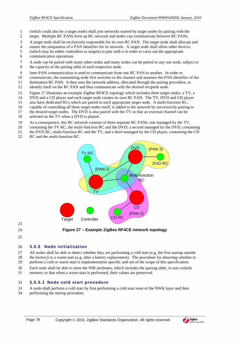
ZigBee RF4CE Specification ZigBee Document 094945r00ZB, January, 2010
Page 78 Copyright 2010, ZigBee Standards Organization. All rights reserved.
(which could also be a target node) shall join networks started by target nodes by pairing with the 1
target. Multiple RC PANs form an RC network and nodes can communicate between RC PANs. 2
A target node shall be exclusively responsible for its own RC PAN. The target node shall allocate and 3
ensure the uniqueness of a PAN identifier for its network. A target node shall allow other devices 4
(which may be either controllers or targets) to pair with it in order to carry out the appropriate 5
communication operations. 6
A node can be paired with many other nodes and many nodes can be paired to any one node, subject to 7
the capacity of the pairing table of each respective node. 8
Inter-PAN communication is used to communicate from one RC PAN to another. In order to 9
communicate, the transmitting node first switches to the channel and assumes the PAN identifier of the 10
destination RC PAN. It then uses the network address, allocated through the pairing procedure, to 11
identify itself on the RC PAN and thus communicate with the desired recipient node. 12
Figure 27 illustrates an example ZigBee RF4CE topology which includes three target nodes: a TV, a 13
DVD and a CD player and each target node creates its own RC PAN. The TV, DVD and CD player 14
also have dedicated RCs which are paired to each appropriate target node. A multi-function RC, 15
capable of controlling all three target nodes itself, is added to the network by successively pairing to 16
the desired target nodes. The DVD is also paired with the TV so that an external channel can be 17
selected on the TV when a DVD is played. 18
As a consequence, this RC network consists of three separate RC PANs: one managed by the TV, 19
containing the TV RC, the multi-function RC and the DVD; a second managed by the DVD, containing 20
the DVD RC, multi-function RC and the TV, and a third managed by the CD player, containing the CD 21
RC and the multi-function RC. 22
TV
DVD
CD
TV RC
DVD RC
CD RC
Multi-function
RC
Target Controller
(PAN 1)
(PAN 2)
(PAN 3)
23
Figure 27 – Example ZigBee RF4CE network topology 24
25
3.5.5 Node init ial izat ion 26
All nodes shall be able to detect whether they are performing a cold start (e.g. the first startup outside 27
the factory) or a warm start (e.g. after a battery replacement). The procedure for detecting whether to 28
perform a cold or warm start is implementation specific and out of the scope of this specification. 29
Each node shall be able to store the NIB attributes, which includes the pairing table, in non volatile 30
memory so that when a warm start is performed, their values are preserved. 31
3.5.5.1 Node cold start procedure 32
A node shall perform a cold start by first performing a cold start reset of the NWK layer and then 33
performing the startup procedure. 34
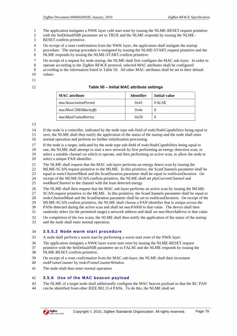
ZigBee Document 094945r00ZB, January, 2010 ZigBee RF4CE Specification
Copyright 2010, ZigBee Standards Organization. All rights reserved. Page 79
The application instigates a NWK layer cold start reset by issuing the NLME-RESET.request primitive 1
with the SetDefaultNIB parameter set to TRUE and the NLME responds by issuing the NLME-2
RESET.confirm primitive. 3
On receipt of a reset confirmation from the NWK layer, the application shall instigate the startup 4
procedure. The startup procedure is instigated by issuing the NLME-START.request primitive and the 5
NLME responds by issuing the NLME-START.confirm primitive. 6
On receipt of a request for node startup, the NLME shall first configure the MAC sub-layer. In order to 7
operate according to the ZigBee RF4CE protocol, selected MAC attributes shall be configured 8
according to the information listed in Table 50. All other MAC attributes shall be set to their default 9
values. 10
11
Table 50 – Initial MAC attribute settings 12
MAC attribute Identifier Initial value
macAssociationPermit 0x41 FALSE
macMaxCSMABackoffs 0x4e 0
macMaxFrameRetries 0x59 0
13
If the node is a controller, indicated by the node type sub-field of nwkcNodeCapabilities being equal to 14
zero, the NLME shall then notify the application of the status of the startup and the node shall enter 15
normal operation and perform no further initialization processing. 16
If the node is a target, indicated by the node type sub-field of nwkcNodeCapabilities being equal to 17
one, the NLME shall attempt to start a new network by first performing an energy detection scan, to 18
select a suitable channel on which to operate, and then performing an active scan, to allow the node to 19
select a unique PAN identifier. 20
The NLME shall request that the MAC sub-layer performs an energy detect scan by issuing the 21
MLME-SCAN.request primitive to the MLME. In this primitive, the ScanChannels parameter shall be 22
equal to nwkcChannelMask and the ScanDuration parameter shall be equal to nwkScanDuration. On 23
receipt of the MLME-SCAN.confirm primitive, the NLME shall set phyCurrentChannel and 24
nwkBaseChannel to the channel with the least detected energy. 25
The NLME shall then request that the MAC sub-layer performs an active scan by issuing the MLME-26
SCAN.request primitive to the MLME. In this primitive, the ScanChannels parameter shall be equal to 27
nwkcChannelMask and the ScanDuration parameter shall be set to nwkScanDuration. On receipt of the 28
MLME-SCAN.confirm primitive, the NLME shall choose a PAN identifier that is unique across the 29
PANs detected during the active scan and shall set macPANId to that value. The device shall then 30
randomly select (in the permitted range) a network address and shall set macShortAddress to that value. 31
On completion of the two scans, the NLME shall then notify the application of the status of the startup 32
and the node shall enter normal operation. 33
3.5.5.2 Node warm start procedure 34
A node shall perform a warm start by performing a warm start reset of the NWK layer. 35
The application instigates a NWK layer warm start reset by issuing the NLME-RESET.request 36
primitive with the SetDefaultNIB parameter set to FALSE and the NLME responds by issuing the 37
NLME-RESET.confirm primitive. 38
On receipt of a reset confirmation from the MAC sub-layer, the NLME shall then increment 39
nwkFrameCounter by nwkcFrameCounterWindow. 40
The node shall then enter normal operation. 41
3.5.6 Use of the MAC beacon payload 42
The NLME of a target node shall additionally configure the MAC beacon payload so that the RC PAN 43
can be identified from other IEEE 802.15.4 PANs. To do this, the NLME shall set 44

ZigBee RF4CE Specification ZigBee Document 094945r00ZB, January, 2010
Page 80 Copyright 2010, ZigBee Standards Organization. All rights reserved.
macBeaconPayloadLength to nwkcMACBeaconPayloadLength and macBeaconPayload to the byte 1
string specified in Figure 28. 2
3
Bits: 0-7 8-9 10-15
Protocol
identifier
Protocol
version
Reserved
Figure 28 – Format of the MAC beacon payload 4
3.5.6.1 Protocol identif ier f ield 5
The protocol identifier field is 8-bits in length and specifies the identifier of the network protocol in 6
use. This field shall always be set to nwkcProtocolIdentifier. 7
3.5.6.2 Protocol version f ield 8
The protocol version field is 8-bits in length and specifies the version of the ZigBee RF4CE protocol. 9
This field shall always be set to nwkcProtocolVersion. 10
3.5.7 Power saving 11
The ZigBee RF4CE power saving mechanism allows a node to conserve power by sleeping for 12
extended periods while still permitting other nodes to communicate with it. To accomplish this, the 13
power saving node periodically wakes, enables its receiver for a short period, handles any incoming 14
frames and then returns to its sleep state. 15
A node shall be assumed to be in power save mode when nwkInPowerSave is equal to TRUE and the 16
node shall be assumed to not be in power save mode when nwkInPowerSave is equal to FALSE. While 17
in power save mode, the node shall not respond to any NWK command frames. 18
Power saving depends on the values of nwkDutyCycle and nwkActivePeriod. The nwkDutyCycle 19
attribute shall define the length of time between successive periods of activity and the nwkActivePeriod 20
attribute shall define the length of time during which the node enables its receiver within each duty 21
cycle. These concepts are illustrated in Figure 29. 22
nwkDutyCycle
nwkActivePeriod
Rx off
Rx on
23 24
Figure 29 – Power saving mechanism concepts 25
26
If nwkDutyCycle is set to 0x000000, the NWK layer shall not utilise or stop using power saving and the 27
application must control the operation of the receiver directly by issuing the NLME-RX-28
ENABLE.request primitive. 29
If nwkDutyCycle is not set to 0x000000, the application may enter or exit power saving by 30
manipulation of the receiver via the NLME-RX-ENABLE.request primitive. A request to enable the 31
receiver shall temporarily disable power saving for the duration of the requested receiver on time. A 32
request to disable the receiver shall enable power saving. 33
From the point power saving is enabled to the point it is disabled, the NLME shall repeatedly 34
manipulate the receiver, as illustrated in Figure 29, i.e. for each duty cycle, the receiver shall be 35

ZigBee Document 094945r00ZB, January, 2010 ZigBee RF4CE Specification
Copyright 2010, ZigBee Standards Organization. All rights reserved. Page 81
enabled for nwkActivePeriod symbols and disabled for the (nwkDutyCycle – nwkActivePeriod) 1
symbols. 2
If any data frames are received during the active period, the NLDE shall process the frames 3
accordingly and then return to its regular duty cycling. If the active period expires while processing an 4
incoming frame received during the active period, the node shall fully process the frame before going 5
back to sleep. 6
7
3.5.8 Transmission, recept ion and acknowledgement 8
Data transmissions from the application are instigated by issuing the NLDE-DATA.request primitive to 9
the NLDE along with the options required for transmission. The NLDE responds by issuing the 10
NLDE-DATA.confirm primitive with an appropriate status value, which may indicate an error. 11
The application is notified of the reception of data via the NLDE-DATA.indication primitive. 12
3.5.8.1 Transmission - general 13
On receipt of a request to transmit a data, network command or vendor-specific data frame, the NLDE 14
shall attempt to generate an NPDU to transport to the recipient via the MAC sub-layer data service. 15
The construction of the NPDU is dependent on the type of frame being transmitted. 16
The ZigBee RF4CE protocol provides the following transmission services: 17
Single channel, acknowledged unicast 18
Multiple channel, acknowledged unicast 19
Single channel, unacknowledged unicast 20
Multiple channel, unacknowledged unicast 21
Single channel, broadcast 22
Multiple channel, broadcast 23
Each of these services is discussed in the following sub-clauses. 24
If the originator is a controller and the recipient is a target, the device shall set macPANId and 25
macShortAddress to the source network address and destination PAN identifier fields from the 26
corresponding pairing table entry before requesting a transmission via the MAC sub-layer. Otherwise, 27
macPANId and macShortAddress shall be left unchanged. 28
Each node shall store its current frame counter value in the NIB attribute nwkFrameCounter and 29
initialize it to 0x00000001. Each time a data, network command or vendor-specific data frame, is 30
generated, the NLDE shall copy the value of nwkFrameCounter into the frame counter field of the 31
NHR of the outgoing frame and then increment it by one. Note that the frame counter shall only be 32
incremented when a frame is generated and not each time a transmission is made during each 33
transmission service attempt. 34
If a transmission request is made with nwkFrameCounter equal to its maximum value (0xffffffff), the 35
NLDE shall notify the application with an error code of FRAME_COUNTER_EXPIRED and perform 36
no further processing. 37
3.5.8.2 Acknowledged unicast t ransmission service 38
The acknowledged unicast transmission service allows a node to transmit a data or vendor-specific data 39
frame to another node while requesting an acknowledgement. The acknowledged unicast transmission 40
service can only be used to transmit frames to other nodes that have entries in the current pairing table 41
of the originating node. A transmission is attempted either on a single channel or on all channels, and 42
an acknowledgement will be requested. Single channel acknowledged unicast transmissions are 43
attempted only on the expected channel up to a fixed number of retries until an acknowledgement is 44
received from the recipient. Multiple channel acknowledged unicast transmissions are attempted on 45
the expected channel for a fixed number of retries and then on each channel repeatedly for a finite duty 46
cycle until an acknowledgement is received from the recipient. 47
On receipt of a request for an acknowledged unicast transmission, the NLDE shall attempt to find the 48
entry in the pairing table that corresponds to the recipient node. If the NLDE does not find a 49
corresponding entry in the pairing table or if the corresponding entry is provisional, it shall return a 50

ZigBee RF4CE Specification ZigBee Document 094945r00ZB, January, 2010
Page 82 Copyright 2010, ZigBee Standards Organization. All rights reserved.
status code of NO_PAIRING. If an entry for the requested recipient exists in the pairing table, the 1
NLDE shall construct the NPDU from the information supplied. The NLDE shall then set 2
macMaxCSMABackoffs and macMaxFrameRetries to the values of nwkMaxFirstAttemptCSMABackoffs 3
and nwkMaxFirstAttemptFrameRetries, respectively. 4
The NLDE shall then request the MAC sub-layer change the value of phyCurrentChannel to the 5
destination logical channel field of the corresponding entry in the pairing table. Controller nodes, in 6
addition, shall request the MAC sub-layer change the values of macPANId and macShortAddress to the 7
destination PAN identifier and source network address fields of the corresponding entry in the pairing 8
table. 9
The NLDE shall then attempt to transmit the frame to the destination by passing the created NPDU to 10
the MAC sub-layer. To do this, the NLDE issues the MCPS-DATA.request primitive to the MAC sub-11
layer (for data frames, see 3.2.2.1.4 and for network command frames, see the description of individual 12
frames in 3.3). The MAC sub-layer confirms the status of the transmission attempt by issuing the 13
MCPS-DATA.confirm to the NLDE. 14
If a single channel acknowledged unicast transmission was requested, when the MAC sub-layer 15
confirms the transmission the NLDE shall pass the status code, indicated by the MAC sub-layer 16
transmission confirmation, to the application by issuing the NLDE-DATA.confirm primitive. The 17
NLDE shall then terminate the transmission procedure. 18
If a multiple channel acknowledged unicast transmission was requested and the MAC sub-layer 19
confirms an unsuccessful transmission, the NLDE shall set both macMaxCSMABackoffs and 20
macMaxFrameRetries to zero. The NLDE shall then request the MAC sub-layer change the value of 21
phyCurrentChannel to the next channel in the sequence and the acknowledged unicast transmission 22
attempt shall be made again. The acknowledged unicast transmission attempt shall be made on each 23
available channel, repeated either for nwkcMaxDutyCycle symbols or until an acknowledgement is 24
received, whichever is sooner. 25
If an acknowledgement is received from the recipient within nwkcMaxDutyCycle symbols, the NLDE 26
shall notify the application with a status code of SUCCESS. The NLDE shall then terminate the 27
transmission procedure. 28
If an acknowledgement is not received from the recipient after nwkcMaxDutyCycle symbols have 29
elapsed, the NLDE shall notify the application with a status code of NO_RESPONSE. The NLDE 30
shall then terminate the transmission procedure. 31
If the transmission attempt was successful and the logical channel on which the transmission was made 32
is different from that stored in the pairing table, the destination logical channel field of the 33
corresponding entry in the pairing table shall be updated with the channel on which the recipient node 34
responded. 35
For a target node, once the transmission has been attempted, the NLDE shall request the MAC sub-36
layer change the value of phyCurrentChannel to nwkBaseChannel. 37
3.5.8.3 Unacknowledged unicast transmission service 38
The unacknowledged unicast transmission service allows a node to transmit a data or vendor-specific 39
data frame to another node but without requesting an acknowledgement. The unacknowledged unicast 40
transmission service can only be used to transmit frames to other nodes that have entries in the current 41
pairing table of the originating node. Each transmission is attempted once, either on a single channel or 42
on all channels, and an acknowledgement will not be requested. 43
On receipt of a request for an unacknowledged unicast transmission from the application, the NLDE 44
shall attempt to find the entry in the pairing table that corresponds to the recipient node. If the NLDE 45
does not find a corresponding entry in the pairing table or if the corresponding entry is provisional, it 46
shall return a status code of NO_PAIRING to the application. If an entry for the requested recipient 47
exists in the pairing table, the NLDE shall construct the NPDU from the information supplied by the 48
application. The NLDE shall then set macMaxCSMABackoffs to the value of 49
nwkMaxFirstAttemptCSMABackoffs. 50
The NLDE shall then request the MAC sub-layer change the value of phyCurrentChannel to the 51
destination logical channel field of the corresponding entry in the pairing table. Controller nodes, in 52
addition, shall request the MAC sub-layer change the values of macPANId and macShortAddress to the 53
destination PAN identifier and source network address fields of the corresponding entry in the pairing 54
table. 55

ZigBee Document 094945r00ZB, January, 2010 ZigBee RF4CE Specification
Copyright 2010, ZigBee Standards Organization. All rights reserved. Page 83
The NLDE shall then attempt to transmit the frame to the destination by passing the created NPDU to 1
the MAC sub-layer. To do this, the NLDE issues the MCPS-DATA.request primitive to the MAC sub-2
layer (see 3.2.2.1.4). The MAC sub-layer confirms the status of the transmission attempt by issuing the 3
MCPS-DATA.confirm to the NLDE. 4
If a single channel unacknowledged unicast transmission was requested, when the MAC sub-layer 5
confirms the transmission, the NLDE shall pass the status code, indicated by the MAC sub-layer 6
transmission confirmation, to the application by issuing the NLDE-DATA.confirm primitive. The 7
NLDE shall then terminate the transmission procedure. 8
If a multiple channel unacknowledged unicast transmission was requested, when the MAC sub-layer 9
confirms the transmission, the NLDE shall request the MAC sub-layer change the value of 10
phyCurrentChannel to the next channel in the sequence and the unacknowledged unicast transmission 11
attempt shall be made again. An unacknowledged unicast transmission attempt shall be repeated once 12
on each channel until the transmission has been attempted on all available channels. The NLDE shall 13
then notify the application with a status code of SUCCESS and the NLDE shall terminate the 14
transmission procedure. 15
For a target node, once the transmission has been attempted, the NLDE shall request the MAC sub-16
layer change the value of phyCurrentChannel to nwkBaseChannel. 17
3.5.8.4 Broadcast t ransmission service 18
The broadcast transmission service allows a node to transmit a data or vendor-specific data frame to all 19
other nodes in its POS. Each transmission is attempted once, either on a single channel or on all 20
channels, and an acknowledgement will not be requested. 21
On receipt of a request for a broadcast transmission from the application or the NLME, the NLDE shall 22
construct the NPDU from the information supplied and appropriate for the individual frame type. The 23
NLDE shall then set macMaxCSMABackoffs to the value of nwkMaxFirstAttemptCSMABackoffs. In 24
addition, the NLDE shall request the MAC sub-layer change the value of phyCurrentChannel to the 25
channel specified by nwkBaseChannel. 26
The NLDE shall then attempt to transmit the frame by passing the created NPDU to the MAC sub-27
layer. To do this, the NLDE issues the MCPS-DATA.request primitive to the MAC sub-layer (for data 28
frames, see 3.2.2.1.4 and for network command frames, see the description of individual frames in 3.3). 29
The MAC sub-layer confirms the status of the transmission attempt by issuing the MCPS-30
DATA.confirm to the NLDE. 31
If a single channel broadcast transmission was requested, when the MAC sub-layer confirms the 32
transmission, the NLDE shall pass the status code, indicated by the MAC sub-layer transmission 33
confirmation, to the application or the NLME by issuing the appropriate primitives. The NLDE shall 34
then terminate the transmission procedure. 35
If a multiple channel broadcast transmission was requested, when the MAC sub-layer confirms the 36
transmission, the NLDE shall request the MAC sub-layer change the value of phyCurrentChannel to 37
the next channel in the sequence and the broadcast transmission attempt shall be made again. A 38
broadcast transmission attempt shall be repeated once on each channel until the transmission has been 39
attempted on all available channels. The NLDE shall then notify the application with a status code of 40
SUCCESS and the NLDE shall terminate the transmission procedure. 41
3.5.8.5 Reception and reject ion 42
The NLDE receives only those frames passed to it by the MAC sub-layer data service, which applies 43
an incoming frame filter (see [R1]), restricting the number of frames delivered to the NWK layer. 44
Similarly, the NLDE shall also apply an incoming frame filter as follows. 45
On receipt of a frame from the MAC sub-layer, the NLDE shall first check the frame type sub-field of 46
the frame control field. If the frame is indicated as having a reserved frame type, the NLDE shall 47
discard the frame. If the frame is indicated as being a network command frame, the NLDE shall pass 48
the frame to the NLME where it shall be processed according to its purpose. If the frame is indicated 49
as being a standard or vendor-specific data frame, the NLDE shall accept only frames that satisfy all of 50
the following first-level filtering requirements (as indicated by the MAC): 51
ZigBee RF4CE Specification ZigBee Document 094945r00ZB, January, 2010
Page 84 Copyright 2010, ZigBee Standards Organization. All rights reserved.
If the source PAN identifier is equal to 0xffff and the source address is indicated as being an 1
IEEE address, it shall match the destination IEEE address field in one of the entries in the 2
pairing table. 3
If the source address is indicated as being a network address, the PAN identifier and the 4
source address shall match the destination PAN identifier and destination network address 5
fields, respectively, of one of the entries in the pairing table. 6
If the source PAN identifier is not equal to 0xffff and the source address is indicated as being 7
an IEEE address, the PAN identifier and the source address shall match the destination PAN 8
identifier and destination IEEE address fields, respectively, in one of the entries in the pairing 9
table. 10
If any of the first-level filtering requirements are not satisfied, the NLDE shall discard the frame 11
without processing it further. If all of the first-level filtering requirements are satisfied, the NLDE shall 12
accept only frames that satisfy all of the second-level filtering requirements (NWK header): 13
If the security enabled sub-field of the frame control field indicates the frame is secured, the 14
security processing (authentication) of the incoming frame shall be successful. 15
The frame counter field shall be greater than the recipient frame counter stored in the 16
corresponding entry of the pairing table entry. 17
18
If any of the second-level filtering requirements are not satisfied, the NLDE shall discard the frame 19
without processing it further. 20
If all of the second-level filtering requirements are satisfied and the frame was secured over a secure 21
pairing link or not secured over an insecure pairing link, the NLDE shall replace the recipient frame 22
counter field of the corresponding entry in the pairing table with the value of the frame counter field in 23
the incoming frame. Otherwise, the recipient frame counter field of the corresponding pairing table 24
entry shall be left unchanged. 25
The NLDE shall then notify the application of the incoming frame. 26
27
3.5.9 Discovering serv ices 28
In order to discover relevant services in the POS of a device, the discovery procedure can be used. 29
Discovery can be used as a pre-requisite to the pairing procedure since it provides the information 30
necessary for creating a pairing link. 31
The NLME can be configured to indicate to the application, never process or to automatically respond 32
to any received discovery request command frames. 33
The result of a discovery operation is a list of node descriptors giving information relating to those 34
nodes that responded to the discovery request. A node shall be able to store between 35
nwkcMinNodeDescListSize and nwkcMaxNodeDescListSize node descriptors. 36
3.5.9.1 Discovery originator procedure 37
For the node performing discovery (the originator) the discovery procedure is initiated by the 38
application by issuing the NLME-DISCOVERY.request primitive and its results transferred to the 39
application via the NLME-DISCOVERY.confirm primitive. 40
A discovery request can be made to all nodes (by setting the destination PAN identifier and destination 41
address both to 0xffff), to nodes on a specific RC PAN (by setting the destination PAN identifier and 42
destination address to the identifier of the desired RC PAN and 0xffff, respectively) or to a specific 43
node (by setting the destination PAN identifier and destination address to the desired values). In 44
addition, a node can discover a specific type of device or any type of device. 45
On receipt of a request to perform discovery, the NLME shall first generate a discovery request 46
command frame (see 3.3.1) with the information supplied by the application. The node requesting 47
discovery shall specify information about itself in order to give sufficient information to a recipient in 48
order to allow it to decide whether to respond. The originator of the discovery request shall specify its 49
node capabilities, its vendor identifier, a vendor-specific identification string, an optional user-specific 50
string relating to this node, a list of supported device types and the list of supported profile identifiers. 51
In addition, the originator specifies the device type it is attempting to discover. 52

ZigBee Document 094945r00ZB, January, 2010 ZigBee RF4CE Specification
Copyright 2010, ZigBee Standards Organization. All rights reserved. Page 85
If the node performing discovery is a controller, it shall ensure macPANId is set to 0xffff before 1
commencing transmission. The NLME shall then transmit the discovery request command frame using 2
the multiple channel data transmission service via the MAC sub-layer data service starting with the 3
channel indicated by the current setting of nwkBaseChannel, if the originator is a target, or an 4
implementation-specific channel otherwise. The discovery request transmission shall be unicast if the 5
discovery is directed to a specific device or broadcast otherwise. If the transmission was not 6
successful, the NLME shall request the MAC sub-layer change the value of phyCurrentChannel to the 7
next channel in the sequence and the transmission attempt shall be made again. The transmission 8
attempt shall be made on each available channel until it is successful or until all channels have been 9
attempted. If the MAC sub-layer confirms the successful transmission of the discovery request 10
command frame, the NLME shall request that the MAC sub-layer enable the receiver for the 11
application specified discovery duration (measured in MAC symbols). During this time, the NLME 12
shall reject all command frames except discovery response command frames. If the MAC sub-layer 13
indicates an unsuccessful transmission, the NLME shall discard that transmission and continue to the 14
next channel in the sequence. 15
The transmission of a discovery request command frame on all available channels is called a discovery 16
trial. 17
A discovery trial shall be performed either nwkMaxDiscoveryRepetitions times, repeated at intervals of 18
nwkDiscoveryRepetitionInterval, or until the discovery is complete, whichever is sooner. 19
During the discovery trial and on receipt of each unique discovery response command frame, the 20
NLME shall check that at least one device type contained in the device type list field matches the 21
search device type supplied by the application and that at least one profile identifier contained in the 22
profile identifier list field matches at least one profile identifier from the discovery profile identifier list 23
supplied by the application. If a match is found, the NLME shall record the information contained in 24
the discovery response command frames in a node descriptor structure (see Table 13). If a match is not 25
found, the NLME shall discard the discovery response command frame. 26
If the number of node descriptors stored at the end of any single discovery trial is equal to 27
nwkMaxReportedNodeDescriptors, the NLME shall notify the application of the list of node 28
descriptors discovered for the devices from which discovery response commands were received and a 29
status code of SUCCESS. 30
If the number of node descriptors stored at the end of any single discovery trial exceeds 31
nwkMaxReportedNodeDescriptors, the NLME shall notify the application with a status code of 32
DISCOVERY_ERROR. 33
If, at any time during the discovery process, the number of node descriptors stored is equal to 34
nwkcMaxNodeDescListSize, the NLME shall notify the application of the list of node descriptors 35
discovered for the devices from which discovery response commands were received and a status code 36
of SUCCESS. 37
If nwkMaxDiscoveryRepetitions discovery trials have been made and the procedure has not yet been 38
terminated as described above, the NLME shall notify the application of the list of node descriptors 39
discovered for the devices from which discovery response commands were received and a status code 40
of SUCCESS. 41
If, at the end of nwkMaxDiscoveryRepetitions discovery trials, no node descriptors are stored, the 42
NLME shall notify the application with a status code of DISCOVERY_TIMEOUT. 43
When notifying the application of the completion of the discovery procedure, the NLME shall also 44
indicate to the application whether all of the discovery trials were complete. 45
3.5.9.2 Discovery recipient procedure 46
For the node receiving a discovery request (the recipient), the application is notified of the reception of 47
a discovery request command frame via the NLME-DISCOVERY.indication primitive, provided 48
nwkIndicateDiscoveryRequests is set to TRUE, and the application responds by issuing the NLME-49
DISCOVERY.response primitive to the NLME. The application is notified of the status of the 50
transmission of the subsequent discovery response command frame via the NLME-COMM-51
STATUS.indication primitive. 52
On receipt of a discovery request command frame (see 3.3.1), if nwkInPowerSave is equal to TRUE or 53
if nwkIndicateDiscoveryRequests is equal to FALSE, the NLME shall discard the frame and perform 54
no further processing. 55

ZigBee RF4CE Specification ZigBee Document 094945r00ZB, January, 2010
Page 86 Copyright 2010, ZigBee Standards Organization. All rights reserved.
On receipt of a discovery request command frame when nwkInPowerSave of the node is equal to 1
FALSE and nwkIndicateDiscoveryRequests is equal to TRUE, the NLME shall first check the LQI of 2
the received frame, as reported by the MAC sub-layer data service. If this value is less than 3
nwkDiscoveryLQIThreshold, the NLME shall reject the discovery request command frame and perform 4
no further processing. If the LQI of the received discovery request command frame is greater than or 5
equal to nwkDiscoveryLQIThreshold, the NLME shall notify the application with the information 6
contained in the frame along with a status of SUCCESS if capacity is available in its pairing table for 7
another pairing link or NO_REC_CAPACITY otherwise. 8
If the application chooses to accept the discovery request, the NLME generates a discovery response 9
command frame (see 3.3.2) with the information supplied from the application. The node responding 10
to the discovery request shall specify information about itself in order to give sufficient information to 11
the originator in order to allow it to decide whether to attempt to pair with this node. The recipient of 12
the discovery request shall specify its node capabilities, its vendor identifier, a vendor specific 13
identification string, an optional user specific string relating to this node, a list of supported device 14
types and the list of supported profile identifiers. 15
The NLME shall then set macMaxCSMABackoffs and macMaxFrameRetries to the values of 16
nwkMaxFirstAttemptCSMABackoffs and nwkMaxFirstAttemptFrameRetries, respectively. 17
The NLME shall then transmit this frame to the originator of the discovery request, via the MAC sub-18
layer data service, using the NLDE unicast, single channel transmission service. The NLME shall then 19
notify the application of the status of the transmission. 20
3.5.9.3 Automatic discovery response 21
Automatic discovery response mode is initiated by the application by issuing the NLME-AUTO-22
DISCOVERY.request primitive and its results transferred to the application via the NLME-AUTO-23
DISCOVERY.confirm primitive. During automatic discovery response mode, 24
nwkIndicateDiscoveryRequests shall be ignored. 25
On receipt of a request to enter automatic discovery response mode, the NLME waits to receive 26
discovery request command frames for at most the specified automatic discovery response mode 27
duration. During this time, the NLME shall discard any non discovery request command frames that 28
are received. 29
On receipt of a discovery request command frame, the NLME shall first check the LQI of the received 30
frame, as reported by the MAC sub-layer data service. If this value is less than 31
nwkDiscoveryLQIThreshold, the NLME shall reject the discovery request command frame. If the LQI 32
of the received discovery request command frame is greater than or equal to 33
nwkDiscoveryLQIThreshold, the NLME shall check that the requested device type field matches one of 34
the device types supplied by the application and that at least one of the profile identifiers listed in the 35
profile identifier list field matches one of the profile identifiers supplied by the application. If a match 36
is found, the NLME shall wait for the reception of a second identical discovery request command 37
frame from the same node and shall again check for a match. 38
If the second discovery request command frame matches the information supplied by the application 39
and is identical to the first discovery request command frame, the NLME shall generate a discovery 40
response command frame (see 3.3.2) with the information supplied from the application. The node 41
responding to the discovery request shall specify information about itself in order to give sufficient 42
information to the originator in order to allow it to decide whether to attempt to pair with this node. 43
The recipient of the discovery request shall specify its node capabilities, its vendor identifier, a vendor 44
specific identification string, an optional user specific string relating to this node, a list of supported 45
device types and the list of supported profile identifiers. 46
The NLME shall then transmit this frame to the originator of the discovery request via the MAC sub-47
layer data service; this transmission shall be unicast back to the originator. The NLME shall then 48
disable automatic discovery response mode and notify the application with a status of SUCCESS. 49
If a second discovery request command frame matches the information supplied by the application but 50
is received from a different node, the NLME shall disable automatic discovery response mode and 51
notify the application with a status of DISCOVERY_ERROR. 52
If a discovery request command frame is received that does not match the information supplied by the 53
application, the NLME shall discard the frame and remain in automatic discovery mode. 54
ZigBee Document 094945r00ZB, January, 2010 ZigBee RF4CE Specification
Copyright 2010, ZigBee Standards Organization. All rights reserved. Page 87
If less than two matching discovery request command frames are received after the requested duration, 1
the NLME shall disable automatic discovery response mode and notify the application with a status of 2
DISCOVERY_TIMEOUT. 3
4
3.5.10 Pairing devices 5
Each node shall maintain a pairing table to track the nodes with which it may communicate. Pairing 6
links shall be bi-directional so an entry shall be created on both the originator (to the recipient) and the 7
recipient (back to the originator). This allows the NLDE to filter incoming frames from nodes that do 8
not appear in the pairing table. 9
A target node shall be able to store at least nwkcMinTargetPairingTableSize entries and a controller 10
node shall be able to store at least nwkcMinControllerPairing-TableSize entries. The pairing table shall 11
be ordered according to a pairing reference that is communicated to the application during pairing. 12
This allows the application to transmit its data using a simple reference rather than having to supply the 13
addressing information required by the MAC sub-layer data service. 14
Pairing shall only be permitted if instigated from a controller to a target or from a target to a target. 15
3.5.10.1 Pairing originator procedure 16
For the node performing pairing (the originator) the pairing procedure is initiated by the application by 17
issuing the NLME-PAIR.request primitive to the NLME and its results and status are transferred to the 18
application via the NLME-PAIR.confirm primitive. 19
On receipt of a pairing request, the NLME shall first check whether it already has an entry in its pairing 20
table corresponding to the pairing recipient. If an entry already exists in the pairing table, the NLME 21
shall store the pairing reference of this entry and update it rather than creating a new entry. If an entry 22
does not already exist in the pairing table, the NLME shall check whether it has capacity in its pairing 23
table for a new entry. If the NLME does not have capacity, it shall notify the application with a status 24
of NO_ORG_CAPACITY and perform no further processing. If the NLME has capacity in its pairing 25
table, it shall store the pairing reference of the next free entry. 26
The NLME shall then generate a pair request command frame as described in 3.3.3 and with the 27
information supplied by the application. 28
The NLME shall then set macMaxCSMABackoffs and macMaxFrameRetries to the values of 29
nwkMaxFirstAttemptCSMABackoffs and nwkMaxFirstAttemptFrameRetries, respectively. In addition, 30
if the node performing pairing is a controller, it shall ensure macPANId is set to 0xffff before 31
commencing transmission. The NLME shall then switch to the requested channel by changing 32
phyCurrentChannel. 33
The NLME shall then transmit the pair request command frame using the multiple channel, 34
acknowledged data transmission service via the MAC sub-layer data service starting with the logical 35
channel supplied by the application. If the transmission was not successful, the NLME shall request 36
the MAC sub-layer change the value of phyCurrentChannel to the next channel in the sequence and the 37
transmission attempt shall be made again. The transmission attempt shall be made on each available 38
channel until it is successful or until all channels have been attempted. If the transmission is still not 39
successful, the NLME shall notify the application with the status returned from the MAC sub-layer and 40
perform no further processing. 41
If the transmission was successful, the NLME shall request that the MAC sub-layer enable the receiver 42
and wait either for nwkResponseWaitTime symbols or until the corresponding pair response command 43
frame is received from the recipient, whichever is sooner. If the expected pair response command 44
frame is not received within nwkResponseWaitTime, the NLME shall notify the application with a 45
status of NO_RESPONSE and perform no further processing. 46
If the expected pair response command frame is received with a status other than SUCCESS, the 47
NLME shall notify the application of the status returned in the pair response command frame and 48
perform no further processing. 49
If the expected pair response command frame is received with a status of SUCCESS, the NLME shall 50
use the information contained in the pair response command frame to create a provisional pairing table 51
entry at the position identified by the pairing reference, stored above. The pairing table entry shall be 52
created as described in Table 51. 53

ZigBee RF4CE Specification ZigBee Document 094945r00ZB, January, 2010
Page 88 Copyright 2010, ZigBee Standards Organization. All rights reserved.
1
Table 51 – Creation of the originator pairing table entry 2
Pairing table entry field Description
Source network address The value of macShortAddress if the node is a target OR
The value of the allocated network address field from the pair
response command frame.
Destination logical channel The logical channel number corresponding to the value of the
channel designator sub-field of the frame control field of the
pair response command frame.
Destination IEEE address The source address from the pair response command frame.
Destination PAN identifier The source PAN identifier from the pair response command
frame.
Destination network address The value of the network address field from the pair response
command frame.
Recipient capabilities The value of the node capabilities field from the pair response
command frame.
Recipient frame counter Reset to 0x00000000.
Security link key Generated later, as necessary.
3
The NLME shall then check whether security is required for this pairing link. If the security enabled 4
bit of both the node capabilities field of the incoming pair response command frame and 5
nwkcNodeCapabilities are not set to one, the NLME shall move the pairing table entry from 6
provisional to active and notify the application with the status code of SUCCESS and the pairing 7
reference at which the pairing table entry was created or updated. 8
If the security enabled bit of both the node capabilities field of the incoming pair response command 9
frame and nwkcNodeCapabilities are set to one, the recipient will generate a security link key for the 10
pairing link and exchange it with the originator. The originator shall recover the key using the 11
procedure described in 3.5.11.2. If the security link key recovery procedure was not successful, the 12
NLME shall remove the provisional pairing table entry and perform no further processing. If the 13
security link key recovery procedure was successful, the NLME shall move the created or updated 14
pairing table entry from provisional to active. 15
The originator shall use the created pairing table entry as described in 3.5.8. 16
3.5.10.2 Pairing recipient procedure 17
For the node receiving a pairing request (the recipient), the application is notified via the NLME-18
PAIR.indication primitive and the application responds by issuing the NLME-PAIR.response primitive 19
to the NLME. The application is notified of the status of the transmission of the pair response 20
command frame via the NLME-COMM-STATUS.indication primitive. 21
If a pairing request command frame (see 3.3.3) is received by a controller, the NLME shall discard the 22
frame, not notify the application and perform no further processing. 23
If a pairing request command frame is received by a target when nwkInPowerSave of the node is equal 24
to TRUE, the NLME shall discard the frame and perform no further processing. 25
If a pairing request command frame is received by a target when nwkInPowerSave of the node is equal 26
to FALSE, the NLME shall first check whether it already has an entry in its pairing table corresponding 27
to the pairing originator. If an entry already exists in the pairing table, the NLME shall store the 28
pairing reference of this entry and update it rather than creating a new entry. 29
If an entry corresponding to the pairing originator does not already exist in the pairing table, the NLME 30
checks whether it has capacity in its pairing table for a new entry. If the NLME does not have 31

ZigBee Document 094945r00ZB, January, 2010 ZigBee RF4CE Specification
Copyright 2010, ZigBee Standards Organization. All rights reserved. Page 89
capacity, it shall notify the application with a status of NO_REC_CAPACITY. If the NLME has 1
capacity in its pairing table for a new entry, the NLME shall store the pairing reference of the next free 2
entry. 3
The NLME shall then use the information contained in the pair request command frame to create or 4
update the pairing table entry at the position identified by the pairing reference, stored above. The 5
pairing table entry shall be created as described in Table 52 and it shall be marked as provisional. 6
7
Table 52 – Creation of the recipient pairing table entry 8
Pairing table entry field Description
Source network address The value of macShortAddress.
Destination logical channel The logical channel number corresponding to the value of the
channel designator sub-field of the frame control field of the
pair request command frame if the originator is a target OR
The value of nwkBaseChannel otherwise.
Destination IEEE address The source address from the pair request command frame.
Destination PAN identifier The source PAN identifier from the pair request command
frame if the originator is a target OR
The value of macPANId otherwise.
Destination network address Allocated if the originator is a controller and the recipient is a
target OR
The value of the network address field from the pair request
command frame otherwise.
Recipient capabilities The value of the node capabilities field from the pair request
command frame.
Recipient frame counter Reset to 0x00000000.
Security link key Generated as necessary on acceptance of the pairing link by
the application.
9
If an existing pairing table entry was updated, the NLME shall notify the application with a status of 10
DUPLICATE_PAIRING and the pairing reference of the updated entry. If a new pairing table entry 11
was created, the NLME shall notify the application with a status of SUCCESS and the pairing 12
reference of the new entry. 13
If the application accepts the pair, it shall respond with a status of SUCCESS. If the application does 14
not wish to accept the pair or if the NLME indicated it did not have capacity for a new entry in its 15
pairing table, it shall respond with a status of NOT_PERMITTED or NO_REC_CAPACITY, 16
respectively. 17
The NLME shall then set macMaxCSMABackoffs and macMaxFrameRetries to the values of 18
nwkMaxFirstAttemptCSMABackoffs and nwkMaxFirstAttemptFrameRetries, respectively. 19
The NLME shall then generate a pair response command frame as described in 3.3.4 with the 20
information supplied from the application. The NLME shall then transmit this frame to the originator 21
of the pair request using the single channel, acknowledged data transmission service via the MAC sub-22
layer data service. If the transmission status was not equal to SUCCESS or if the transmission status 23
was equal to SUCCESS but the application did not wish to accept the pair, the NLME shall remove the 24
provisional pairing table entry and perform no further processing. 25
The NLME shall then check whether security is required for this pairing link. If the security enabled 26
bit of both the node capabilities field of the incoming pair request command frame and 27

ZigBee RF4CE Specification ZigBee Document 094945r00ZB, January, 2010
Page 90 Copyright 2010, ZigBee Standards Organization. All rights reserved.
nwkcNodeCapabilities are not set to one, the NLME shall move the created pairing table entry from 1
provisional to active. 2
If the security enabled bit of both the node capabilities field of the incoming pair request command 3
frame and nwkcNodeCapabilities are set to one, the NLME shall generate a security link key for the 4
pairing link and exchange it with the originator using the procedure described in 3.5.11.1. If the 5
security link key exchange procedure was not successful, the NLME shall remove the provisional 6
pairing table entry and perform no further processing. If the security link key exchange procedure was 7
successful, the NLME shall move the created pairing table entry from provisional to active. 8
The recipient shall use the created pairing table entry as described in 3.5.8. 9
3.5.10.3 Removing a pair ing l ink 10
The procedure for removing a pairing link is initiated by the local application by issuing the NLME-11
UNPAIR.request primitive to the NLME and indicated to the remote application via the NLME-12
UNPAIR.indication primitive. Once the remote application has extracted any information, necessary to 13
inform the user, from the pairing table it issues the NLME-UNPAIR.response primitive to the NLME. 14
The status of the unpair are transferred to the local application via the NLME-UNPAIR.confirm 15
primitive. 16
On receipt of a request to remove a pairing link, the NLME shall first check whether the requested 17
pairing reference exists in the pairing table. If a corresponding entry does not exist in the pairing table, 18
the NLME shall notify the application with an error code of NO_PAIRING. If a corresponding entry 19
exists in the pairing table, the NLME shall generate an unpair request command frame as described in 20
3.3.5. 21
If a link key exists for the corresponding entry in the pairing table, the NLME shall securely process 22
the unpair request frame before transmission using the procedure described in 3.5.11 and with the link 23
key from the pairing table entry. Otherwise, the unpair request command frame shall be sent without 24
security. 25
The NLME shall then transmit the unpair request command frame to the device listed in the pairing 26
table entry using the multiple channel, acknowledged data transmission service via the MAC sub-layer 27
data service starting with the channel indicated in the pairing table entry. If the transmission was not 28
successful, the NLME shall request the MAC sub-layer change the value of phyCurrentChannel to the 29
next channel in the sequence and the transmission attempt shall be made again. The transmission 30
attempt shall be made on each available channel until it is successful or until all channels have been 31
attempted. On completion of the transmission attempt (regardless of its success), the NLME shall 32
delete the requested pairing table entry and the application shall be notified of the status of the 33
transmission. 34
On receipt of an unpair request command frame (see 3.3.5), the NLME shall verify the security on the 35
frame. If the unpair request command frame was sent without security but the pairing link is secure, 36
the NLME shall discard the frame and the NLME shall perform no further processing. If the unpair 37
request command frame was sent with security, the NLME shall securely process the incoming frame 38
as described in 3.5.11. If the secure processing of the incoming frame fails, the NLME shall discard 39
the frame and the NLME shall perform no further processing. 40
Once the security of the incoming unpair request command frame has been verified, the NLME shall 41
locate the entry in its pairing table that corresponds to the device that transmitted the frame. If an entry 42
is found, the NLME shall notify the application, indicating the reference of the pairing table entry to be 43
deleted. The application may then extract any information from the pairing table that is necessary to 44
inform the user. When the application has all the information it requires from the pairing table entry, it 45
shall indicate to the NLME that the entry can be deleted. The NLME shall then remove the entry from 46
the pairing table. 47
48
3.5.11 Security 49
A node shall indicate that it is capable of applying security through the security capable sub-field of 50
nwkcNodeCapabilities having the value one. 51
A unique and random security key shall be established for each communication link during the pairing 52
procedure. If both nodes are capable of applying security, as indicated by the node capabilities field 53
ZigBee Document 094945r00ZB, January, 2010 ZigBee RF4CE Specification
Copyright 2010, ZigBee Standards Organization. All rights reserved. Page 91
that is exchanged by the devices, a key shall be generated and exchanged as described in sub-clause 1
3.5.11.1. 2
Each node shall maintain a 4 octet network frame counter, nwkFrameCounter, in its NIB table. This 3
counter is initialized to 0x00000001 when the node is first initialized and is then incremented by one 4
each time a packet is generated for transmission. 5
Additionally, a node shall store the network frame counter of each of the nodes it is paired with in the 6
recipient frame counter field of the corresponding entries in the pairing table. This value is initialized 7
to zero when the pairing table entry is created and is updated each time it successfully receives a 8
secured packet from the corresponding node. 9
The ZigBee RF4CE frame security shall use the CCM* mode of operation as described in Annex B of 10
[R1] . This operation uses the AES-128 block cipher algorithm. The parameter M shall have a value of 11
4. 12
In the following sub-sections, the concatenated fields are represented in the order where the leftmost 13
field occupies the lower order bytes. 14
3.5.11.1 Target l ink key exchange procedure 15
The target link key exchange procedure shall be instigated following the successful transmission of the 16
pair response command frame back to the originator. 17
The NLME shall generate a 128-bit security link key for the pairing link and attempt to transfer it to the 18
originator of the pair request command frame. To transfer the key, the NLME shall send (n + 1) key 19
seed command frames to the pairing originator, where n shall be equal to the value of the key exchange 20
transfer count field of the pair request command frame. During the transfer the NLME shall set 21
macMaxFrame-Retries to zero and each transmission shall use the single channel, acknowledged data 22
transmission service. 23
The transfer of all key seeds (and any necessary re-transmissions of key seeds) shall take no longer 24
than ((n + 1) * nwkcMaxKeySeed-WaitTime) symbols. If all the transfers do not complete within this 25
time, the security link key exchange procedure shall be considered unsuccessful and the NLME shall 26
notify the application with a communication status of SECURITY_TIMEOUT and return to the pairing 27
procedure. 28
For each transmission of the key seed command frame, the NLME shall increment the seed sequence 29
number field, starting from 0x00. For the first n seed transmissions, the seed data field shall contain an 30
80-octet random number. For the (n + 1)th
seed transmission, the seed data field is a special case and 31
shall be computed in two phases: 32
1. Generate four 128-bit random numbers and concatenate them together along with the result 33
of the XOR of each of those four random numbers and the 128-bit security link key 34
generated above. 35
2. Compute the XOR of all of the previous random numbers sent in the first n key seed 36
transmissions and the result of phase 1. 37
38
The seed data field of the final key seed transmission shall then be set to the value computed in phase 39
2. These computations are illustrated in Figure 30. 40
If an acknowledgement is not received for any of the key seed command frames, the NLME shall 41
regenerate the appropriate random parts of the seed data field, while keeping the seed sequence number 42
field the same and re-transmit the key seed command frame to the pairing originator provided that the 43
maximum transfer time of ((n + 1) * nwkcMaxKeySeedWaitTime) symbols is not exceeded. 44
If all transfers are received within ((n + 1) * nwkcMaxKeySeedWaitTime) symbols, the NLME shall 45
wait either for nwkResponseWaitTime symbols or until a ping request command frame is received from 46
the originator of the pair request command frame, whichever is sooner. If a ping request command 47
frame is not received within nwkResponseWaitTime, the security link key exchange procedure shall be 48
considered unsuccessful and the NLME shall notify the application with a communication status of 49
SECURITY_FAILURE and return to the pairing procedure. 50
If a ping request command frame is received within nwkResponseWaitTime, the NLME shall verify that 51
the ping request was received as a secured transmission, that the ping options field is equal to 0x00 and 52
that the ping payload field was 4 octets in length. If the ping request command frame cannot be 53

ZigBee RF4CE Specification ZigBee Document 094945r00ZB, January, 2010
Page 92 Copyright 2010, ZigBee Standards Organization. All rights reserved.
verified in this way, the security link key exchange procedure shall be considered unsuccessful and the 1
NLME shall notify the application with a communication status of SECURITY_FAILURE and return 2
to the pairing procedure. 3
If the ping request command frame was verified as described above, the NLME shall generate a ping 4
response command frame and transmit it back to the originator of the ping request command frame 5
using the secure data transmission service via the MAC sub-layer data service. The ping options and 6
ping payload fields shall contain the same values of the corresponding fields of the ping request 7
command frame. 8
The NLME shall then notify the application of the status of the transmission. If the transmission was 9
unsuccessful, the security link key exchange procedure shall also be considered unsuccessful. 10
Conversely, if the transmission was successful, the security link key exchange procedure shall also be 11
considered successful. The NLME shall then return to the pairing procedure. 12
01010101...1
r1 = 80-octet random number
00110011...1
r2 = 80-octet random number
00011100...1
rn = 80-octet random number
00001111...1
rn+1 = r1 Å r2 Å ... Å rn Å <Seed data for seed n+1>
Seed sequence number: 0
Seed sequence number: 1
Seed sequence number: n-1
Seed sequence number: n
Seed data field
a) Seed data for the key seed transmissions b) Computing the seed data for seed n+1
rs1 rs2 rs3 rs4 rs510101010...0
11001100...0
11100011...1
11110000...0
01111010...1
128-bit random number rs1
128-bit random number rs2
128-bit random number rs3
128-bit random number rs4
rs5 = rs1 Å rs2 Å rs3 Å rs4 Å <LinkKey>
<Seed data for seed n+1>
128-bit
<LinkKey>
...
LSB MSB
13
Figure 30 – Target side link key exchange 14
3.5.11.2 Pairing originator l ink key recovery procedure 15
The originator link key recovery procedure shall be instigated following the successful reception of the 16
pair response command frame from the pairing recipient. 17
The NLME shall wait for the reception of (n + 1) key seed command frames from the target, where n 18
shall be equal to the value of the key exchange transfer count field of the pair request command frame 19
sent by this node. All key seeds shall be received within ((n + 1) * nwkcMaxKeySeedWaitTime) 20
symbols. If all the transfers are not received within this time, the security link key recovery procedure 21
shall be considered unsuccessful and the NLME shall notify the application with a status of 22
SECURITY_TIMEOUT and return to the pairing procedure. 23
If all transfers are successfully received within ((n + 1) * nwkcMaxKeySeedWaitTime) symbols, the 24
NLME shall compute the link key in two phases: 25
1. Compute the XOR of the seed data fields from each of the (n + 1) key seed command frames. 26
2. Divide the result of phase 1 into five 128-bit blocks and compute their XOR. 27
28
The link key shall then be set to the result of phase 2. These computations are illustrated in Figure 31. 29

ZigBee Document 094945r00ZB, January, 2010 ZigBee RF4CE Specification
Copyright 2010, ZigBee Standards Organization. All rights reserved. Page 93
01010101...1
00110011...1
r2
00011100...1
00001111...1
Seed sequence number: 0
Seed sequence number: 1
Seed sequence number: n-1
Seed sequence number: n
r1
rn
rn+1
10101010...1
Å
Å
Å
...
<Seed data for seed n+1>
rs1 rs2 rs3 rs4 rs5
Å
Å
Å
Å
128-bit
<LinkKey>
<Seed data for seed n+1>
a) Processing the received seed data b) Computing the link key
Seed data field
LSB MSB
1
Figure 31 – Pairing originator side link key exchange 2
The NLME shall then set macPANId to either 0xffff or the destination PAN identifier field of the 3
provisional pairing table entry created on receipt of the pair response command frame from the pairing 4
recipient. The NLME shall then generate a ping request command frame and transmit it to the 5
recipient of the pair request command frame using the secure data transmission service via the MAC 6
sub-layer data service. The ping options field shall contain 0x00 and the ping payload field shall 7
contain a 4 octet random value. 8
If the transmission was not successful, the security link key recovery procedure shall be considered 9
unsuccessful and the NLME shall notify the application with the status returned from the MAC sub-10
layer and return to the pairing procedure. 11
If the transmission was successful, the NLME shall request that the MAC sub-layer enable the receiver 12
and wait either for nwkResponseWaitTime symbols or until a ping response command frame is received 13
from the recipient of the pair request command frame, whichever is sooner. If a ping response 14
command frame is not received within nwkResponseWaitTime, the security link key recovery 15
procedure shall be considered unsuccessful and the NLME shall notify the application with a status of 16
NO_RESPONSE and return to the pairing procedure. 17
If a ping response command frame is received within nwkResponseWaitTime, the NLME shall verify 18
that the ping response was received as a secured transmission and that the ping options and the ping 19
payload fields contain the same values as was sent in the ping request command frame. If the ping 20
response command frame cannot be verified in this way, the security link key recovery procedure shall 21
be considered unsuccessful and the NLME shall notify the application with a status of 22
SECURITY_FAILURE and return to the pairing procedure. 23
If the ping response command frame can be verified in this way, the security link key recovery 24
procedure shall be considered successful and the NLME shall notify the application with a status of 25
SUCCESS and return to the pairing procedure. 26
3.5.11.3 Outgoing frame security 27
An outgoing ZigBee RF4CE network frame (NPDU) shall be secured according to the procedure 28
described in section B.4.1 in [R1] . 29
30
The inputs to the operation are as follows 31
The Key key shall be set to the security link key field from the pairing table entry 32
corresponding to the recipient. 33
ZigBee RF4CE Specification ZigBee Document 094945r00ZB, January, 2010
Page 94 Copyright 2010, ZigBee Standards Organization. All rights reserved.
The nonce N shall be formed by the concatenation of the following fields: 1
SrcIEEEAddr || FrameCounter || SecurityLevel 2
3
SrcIEEEAddr shall be the 8-byte IEEE address of the node performing this security 4
operation, i.e. aExtendedAddress. FrameCounter shall be set to the 4-byte frame 5
counter field from the NHR of the outgoing frame. SecurityLevel shall be set to the 6
1-byte value of 0x05. 7
The octet string a shall be formed by the concatenation of the following fields: 8
FrameControl || FrameCounter || DstIEEEAddr 9
10
FrameControl shall be set to the 1-byte frame control field in the NHR of the 11
outgoing frame. FrameCounter shall be set to the 4-byte Frame counter field in the 12
NHR of the outgoing frame. DstIEEEAddr shall be set to the 8-byte destination 13
IEEE address field from the pairing table entry corresponding to the recipient. 14
The octet string m shall be set to the ZigBee RF4CE network payload (NSDU). 15
16
Upon completion of the security operation, the encrypted message ciphertext C and the encrypted 17
authentication tag U are generated. 18
The ciphertext C shall replace the ZigBee RF4CE network payload (NSDU). The tag U shall replace 19
the Message integrity code (NFR) in the ZigBee RF4CE frame. 20
21
3.5.11.4 Incoming frame security 22
A secured incoming ZigBee RF4CE network frame shall be un-secured according to the procedure 23
described in section B.4.2 in [R1] . 24
The inputs to the operation are as follows: 25
The Key key shall be set to the security link key field from the pairing table entry 26
corresponding to the originator. 27
The nonce N shall be formed by the concatenation of the following fields: 28
SrcIEEEAddr || FrameCounter || SecurityLevel 29
30
SrcIEEEAddr shall be set to the 8-byte Destination IEEE address field from the 31
pairing table entry corresponding to the MAC source address of the incoming frame. 32
FrameCounter shall be set to the 4-byte frame counter field from the NHR of the 33
incoming frame. SecurityLevel shall be set to the 1-byte value of 0x05. 34
The octet string c shall be formed by the concatenation of the following fields from the 35
incoming frame: 36
NWK payload || NFR 37
The octet string a shall be formed by the concatenation of the following fields: 38
FrameControl || FrameCounter || DstIEEEAddr 39
40
FrameControl shall be set to the 1-byte frame control field in the NHR of the 41
incoming frame. FrameCounter shall be set to the 4-byte Frame counter field in the 42
NHR of the incoming frame. DstIEEEAddr shall be set to the 8-byte IEEE address 43
of the node performing this operation, i.e. aExtendedAddress. 44
45
Upon completion of the security operation, if the verification of the authentication tag fails, the 46
incoming frame shall be discarded. 47
Otherwise, the NWK payload of the incoming frame shall be replaced by the output string m and the 48
recipient frame counter field in the pairing table entry corresponding to the originator of the incoming 49
frame shall be replaced by the network frame counter field in the NHR of the incoming frame. 50

ZigBee Document 094945r00ZB, January, 2010 ZigBee RF4CE Specification
Copyright 2010, ZigBee Standards Organization. All rights reserved. Page 95
4 Revision History 1
Version Date Details Editor
0.5 April 2008 Initial draft. Phil Jamieson
0.75 August 2008 Update following technical working group informal review.
Phil Jamieson
0.85 September 2008 Further updates to add security and application profile protocols, plus comments from the membership.
Phil Jamieson
0.90 October 2008 Updates following technical working group review and network pre-test event. CERC profile split into separate document (080007).
Phil Jamieson
0.91 November 2008 Updates following 0.90 review and CERC profile test event.
Phil Jamieson
0.93 December 2008 Updates following 0.91 and evaluators review. Phil Jamieson
0.95 December 2008 Frame control reserved sub-field change. Specification approved by the TWG as a v1.00 release candidate.
Phil Jamieson
1.00 December 2008 Specification approved by the RF4CE founders. Phil Jamieson
1.01 January 2010 Minor update comprising errata specified in 095035. Phil Jamieson
2
3
ZigBee RF4CE Specification ZigBee Document 094945r00ZB, January, 2010
Page 96 Copyright 2010, ZigBee Standards Organization. All rights reserved.
5 Annex A: Frame security processing example 1
The following data is taken from the RF4CE Golden Unit test logs (file name: TC 7-1 DUT TI 2
target FS DUT controller). 3
4
The ping request command packet is illustrated in this example. 5
6
All fields are shown in the order of the over-the-air transmission (lowest order byte first) 7
8
The parameters are as follows 9
IEEE addresss of the source device is aa aa aa aa aa aa aa aa 10
IEEE address of the destination device is 01 00 00 00 00 00 00 00 11
Frame counter is 03 00 00 00 12
Link Key is b4 b7 16 ce 54 5f f8 22 19 6a ef ec 8d 05 03 01 13
14
The inputs to the CCM* mode forward transformation are as follows: 15
16
a) Key as noted above 17
b) The nonce N of 15-L = 13 octets to be used: 18
Nonce = AA AA AA AA AA AA AA AA || 03 00 00 00||05 19
Note that the IEEE Source address and Frame count are LSB first order 20
c) The octet string m of length l(m)= 6 octets to be used: 21
m = 07 00 ae bc d1 5c 22
d) The octet string a of length l(a) = 13 octets to be used 23
a = 2E || 03 00 00 00 || 01 00 00 00 00 00 00 00 24
The Ping request (cmdId = 0x07) is transmitted with the Ping Options set to 0x00 and Ping 25
Payload set to ae bc d1 5c 26
27
Unsecured frame = NHR || NSDU 28
29
2e 03 00 00 00 07 00 ae bc d1 5c 30
31
Upon applying the outgoing security operations as described in the specification, the following output 32
should be achieved 33
34
Ciphertext is 2d 44 bc dc ef 9b 35
Message Integrity Code is 6b b9 31 3d 36
37
The complete network frame (msdu) as seen over-air is 38
39
Secured network frame = NHR || Ciphertext || MIC 40
41
2e 03 00 00 00 2d 44 bc dc ef 9b 6b b9 31 3d 42
43


![ZigBee Stack Profile: Platform restrictions for compliant ...read.pudn.com/.../3...ZigBee-Feature-Set-Profile.pdf · 11 [R2] ZigBee 04140r05, ZigBee Protocol Stack Settable Values](https://static.fdocuments.in/doc/165x107/5f183a7d6417c0751a61665e/zigbee-stack-profile-platform-restrictions-for-compliant-readpudncom3zigbee-feature-set-.jpg)