ZENER DIODES AND REGULATORS - ece.uprm.edumtoledo/web/4201/F2018/Slides/ex1/Zener-new.pdf · INEL...
17
ZENER DIODES AND REGULATORS Textbook section 4.4 INEL 4201 Electronics I 1
Transcript of ZENER DIODES AND REGULATORS - ece.uprm.edumtoledo/web/4201/F2018/Slides/ex1/Zener-new.pdf · INEL...

ZENER DIODES AND REGULATORS
Textbook section 4.4
INEL 4201 Electronics I
1

Oxford University PublishingMicroelectronic Circuits by Adel S. Sedra and Kenneth C. Smith
(0195323033)
4.2. Terminal Characteristics
of Junction Diodes
▪ Most common implementation of a diode utilizes pn junction.
▪ I-V curve consists of three characteristic regions▪ forward bias: v > 0▪ reverse bias: v < 0▪ breakdown: v << 0
discontinuity caused by differences in scale
!2

Oxford University PublishingMicroelectronic Circuits by Adel S. Sedra and Kenneth C. Smith
(0195323033)
= − Si I<< − Si I −= / Tv VSi I e
V =
-VZK
V =
-VT
V =
10V T
= −/( 1)Tv VSi I e
!3
-
vD
+
iD
VZ
Zener diodes - reverse-bias operation - keeps an approx. constant voltage independent of diode’s current
- Operation in this regime can destroy a regular diode
4

R
5
VPS
R
Let:
• VZ : Zener diode’s nominal voltage.
• iZ,min : minimum current through diode required for proper operation.
• iL,max, iL,min : maximum and minimum load’s current.
• VS,max, VS,max : maximum and minimum source voltage levels
For proper operation, select R so that
R VS,min � VZ
iZ,min + iL,max
Maximum power dissipated in the resistor:
PR,max =(VS,max � VZ)2
R
Maximum power dissipated in the diode:
PD,max = VZ ⇥✓VS,max � VZ
R� iL,min
◆
D and R must have a power rating greater than PD,max and PR,max, respec-tively.

6

Voltage regulatorVS R
Let:
• VZ : Zener diode’s nominal voltage.
• iZ,min : minimum current through diode required for proper operation.
• iL,max, iL,min : maximum and minimum load’s current.
• VS,max, VS,max : maximum and minimum source voltage levels
For proper operation, select R so that
R VS,min � VZ
iZ,min + iL,max
Maximum power dissipated in the resistor:
PR,max =(VS,max � VZ)2
R
Maximum power dissipated in the diode:
PD,max = VZ ⇥✓VS,max � VZ
R� iL,min
◆
D and R must have a power rating greater than PD,max and PR,max, respec-tively.
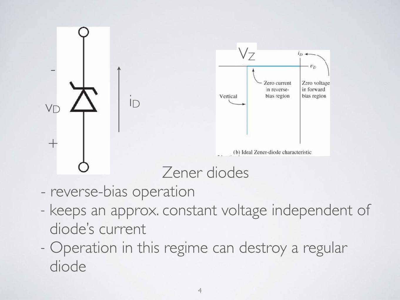
• Minimum zener current ≥ iZ, min when load current = iL, max
• VZ is specified at a specific current; use piece-wise linear model to estimate the diode’s voltage at a different current
7
8
=>
rZ
VZ
+−VS
R1
D1 RLvL
+
-
+−VS
R1
D1RL vL
+
-
rZ
VZ
=>
Piece-wise linear approx.iD
vD
iD vD
+
-
VZ
slope = 1/rZ

9

PROB. 4.61• Design a regulator with output voltage VL = 7.5V
• VZ = 7.5V at IZ = 12mA
• Iknee (minimum) current is 0.5mA
• incremental resistance rz = 30Ω
• Power Supply: VPS = 10V
• Load: RL = 1.2kΩ
10

PROB. 4.61 DESIGN
IL =7.5V
1.2k�= 6.25mA
IR = IL + IZ = 12mA + 6.25mA = 18.25mA
R =VPS � VL
IR=
10V � 7.5V
18.25mA� 137�
11

10V
139.51
RL12001 10V
139.51
RL12001
301
7.14V
IZIL
IR
What's the output voltage if the supply is 10% high?
Extrapolate to find VZ0
VZ0 = 7.5V − 30Ω × 12mA = 7.14V
10V
139.51
RL12001 10V
139.51
RL12001
301
7.14V
IZIL
IR
137Ω
10V + ΔVPS
10V
139.51
RL12001 10V
139.51
RL12001
301
7.14V
IZIL
IR
137Ω
ΔVPS ΔvO = ΔVPS30Ω∥1200Ω
30Ω∥1200Ω + 137Ω= 0.176V
+
-
137Ω

10V
139.51
RL12001 10V
139.51
RL12001
301
7.14V
IZIL
IR
What’s the output voltage if the supply is 10% high?
VZ = IZ � 30� + VZ0 � VZ0 = 7.5V � 12mA � 30� = 7.14VVPS � VL
R=
VL � 7.14V
30�+
VL
RL
VL = (R�30��RL)
�VPS
R+
7.14V
30�
�
For R = 137�, VPS = 10V and RL = 1200�,
VL = (24.116�)
�10V
137�+
7.14V
30�
�= 7.5V
as expected. For VPS = 11V ,
VL = (24.116�)
�11V
137�+
7.14V
30�
�= 7.676V
13
137Ω137ΩAnother way

What's the output voltage when both the supply is 10% high and the load is removed?

15
What's the smallest load resistor that can be used while the zener operates at a current no lower than the knee current while the supply is 10% low? What's the load voltage in this case?

Exercise 4.16: A zener diode whose nominal voltage is 10 V at 10 mA has an incremental resistance of 50 Ω. What voltage do you expect if the diode current is halved? Doubled? What is the value of VZ0 in the zener model?
16

INEL 4201 – Diodes 9/14/2015
Exercise 4.17 A zener diode exhibit a constant voltage of 5.6V for current greater than five times the knee current. IZK is specified to be 1mA. The zener is to be used in the design of a shunt regulator fed from a 15-V supply. The load current varies over the range of 0mA to 15mA. Find a suitable value for the resistor R. What is the maximum power dissipation of the zener diode?