Zehnder Linear Radiant Ceiling Panels Installation ... · Heating Cooling Fresh Air Clean Air...
32
Cooling Fresh Air Clean Air Heating Zehnder Linear Radiant Ceiling Panels Installation, Operation and Maintenance
Transcript of Zehnder Linear Radiant Ceiling Panels Installation ... · Heating Cooling Fresh Air Clean Air...

Cooling Fresh Air Clean AirHeating
Zehnder Linear Radiant Ceiling Panels
Installation, Operation and Maintenance

ii
General information 1Safety considerations 2Receiving 3 Unpacking and preparation 4Storage 4Dimensions and data 5Handling and installation 6Suspension 8Installation 10Water system 19Piping connections 20Water connections 26Start up, operation, maintenance and cleaning 27Replacement parts 28 Start-up check list 28
IMPORTANT: Submittal documentation, specific to each project, supersedes the general guidelines contained within this manual.

General information This installation and start-up instructions literature is for Linear Radiant Ceiling Panels. Radiant ceiling panels are hydronic units designed for year-round cooling and heating. Your equipment is initially protected under the Zehnder Rittling standard one year warranty provided the steps outlined in this manual for initial inspection, installation, periodic maintenance and normal every day operation of the equipment are followed. This manual should be thoroughly reviewed prior to the installation, start-up or maintenance of the equipment. If any questions arise, please contact your local Zehnder Rittling sales representative or the factory before proceeding any further.
Linear Radiant Ceiling Panels are a vital part of a building's heating/cooling system and therefore must be properly maintained to provide many years of trouble-free heating/cooling. As long as the following procedures are followed, the system will remain problem-free.
1General information

The installation of Linear Radiant Ceiling Panels and all associated components, parts and accessories which make up the installation, shall be in accordance with the regulations of all authorities having jurisdiction and must conform to all applicable codes. Only trained and qualified service personnel using good judgment and safe practices should install, repair and/or service air conditioning equipment.
Untrained personnel can perform basic maintenance functions such as cleaning panels. All other operations should be performed by trained service personnel. When working on air conditioning equipment, observe precautions in the literature, tags and labels attached to the equipment and all other safety precautions that may apply.
Improper installation, adjustment, alteration, service, maintenance, or use can cause hazardous conditions which may cause serious personal injury and/or property damage. Consult a qualified installer, service agency, or your sales representative for information or assistance.
The equipment must always be properly supported by rigging and lifting equipment. Any temporary supports used during installation or maintenance must be designed to adequately hold the equipment in place until equipment is permanently fastened and set in its final location. All supports must meet applicable local codes and ordinances.
All fastening devices must be designed to mechanically hold the assembly in place without the ability to loosen or break away due to system operation or vibration.
Gloves should always be worn for protection against heat, sharp edges and all other possible hazards. Safety glasses should always be worn, especially when drilling, cutting or working with chemicals.
Never pressurize equipment beyond specified pressures. Always pressure test with an inert fluid such as water or dry nitrogen to avoid possible damage or injury in the event of a leak or component failure during testing.
Please follow standard safe practices regarding the handling, installing or servicing of mechanical equipment.
Read these instructions thoroughly and follow all warnings or cautions attached to the equipment. Consult local building codes for special installation requirements.
Understand the signal words: danger, warning and caution.
Identifies the most serious hazards which will result in severe personal injury or death.
Signifies hazards that could result in personal injury or death.
Used to identify unsafe practices, which would result in minor personal injury or product and property damage.
The manufacturer assumes no responsibility for personal injury or property damage resulting from improper or unsafe practices during the handling, installation, service or operation of the equipment. The installation of Linear Radiant Ceiling Panels and all associated components, parts and accessories shall be in accordance with the regulations of all authorities having jurisdiction and must conform to all applicable codes. It is the responsibility of the installing contractor to determine and comply with all applicable codes and regulations.
Safety considerations
2

Receiving
Upon delivery, examine the shipment against the bill of lading to make sure all of the panels have been received and then check each panel carefully for shipping damage. Any damage should be reported to the freight carrier and a claim should be filed with them. Ensure the shipping company makes proper notation of any shortages or damage on all copies of the freight bill. Concealed damage not discovered during unloading must be reported to the shipping company within 15 days of receipt of the shipment.
All panels are shipped F.O.B. factory. Therefore, Zehnder Rittling is not responsible for damage during transit. It is the responsibility of the installing contractor to inspect and verify that the panels shipped were in fact the correct type, length, etc. Any discrepancies should be reported to the local Sales Representative for immediate resolution prior to unpackaging and installation. The factory should be notified of any warranty repairs required in writing before any corrective action is taken. The factory must be fully informed of the expected costs before the work is begun. Zehnder Rittling is not responsible for any repairs or alterations made by the purchaser
without Zehnder Rittling’s written consent and will not accept any back charges associated with these repairs or alterations. The return of damaged equipment will not be accepted without written authorization from Zehnder Rittling.
A unit that has received a written Return Goods Authorization will be inspected by Zehnder Rittling upon receipt. Any damage, missing parts, reworking or repackaging resulting from prior installation will constitute just cause for Zehnder Rittling to issue partial credit.
3

4
Storage
Linear ceiling panels must be stored on edge in a back-to-back and face-to-face alternating pattern.
Improper storage configuration could result in damage to the panel.
Unpacking and preparation
All panels are carefully inspected at the factory throughout the entire fabrication and assembly processes under Zehnder Rittling’s stringent quality assurance program.
It is the sole responsibility of the customer to provide the protection necessary to prevent vandalism and weather deterioration of the equipment. Under no condition should the panels be left unprotected from the elements. If the equipment is not needed immediately at the job site, it should be left in its shipping carton and stored in a clean, dry area of the building or in a warehouse. Do not remove
any equipment from its shipping package until it is needed for installation. The equipment is NOT suitable for outdoor installations.
Carefully remove each panel from the container and inspect for hidden damage. Any hidden damage should be recorded and immediately reported to the carrier and a claim should be filed. In the event a claim for shipping damage is filed, the panel shipping container, and all packing must be kept for physical inspection by the freight carrier.
Cap open ends of piping that are stored on a job site. Take special care to prevent foreign materials from entering the piping in areas where painting, dry walling, or spraying of fireproof material, etc., has not yet been completed. Before installing
any of the system components, be sure to examine each pipe, fitting and valve, and remove any dirt or foreign material found in or on these components. Some job conditions may require some form of temporary unit covering during construction.
DO NOT store or install panels in corrosive environments or in locations subject to temperature or humidity extremes (e.g., attics, garages, rooftops, etc.). Corrosive conditions and high temperature or humidity can significantly reduce system performance, reliability and overall service life.
Unpacking and preparation
5
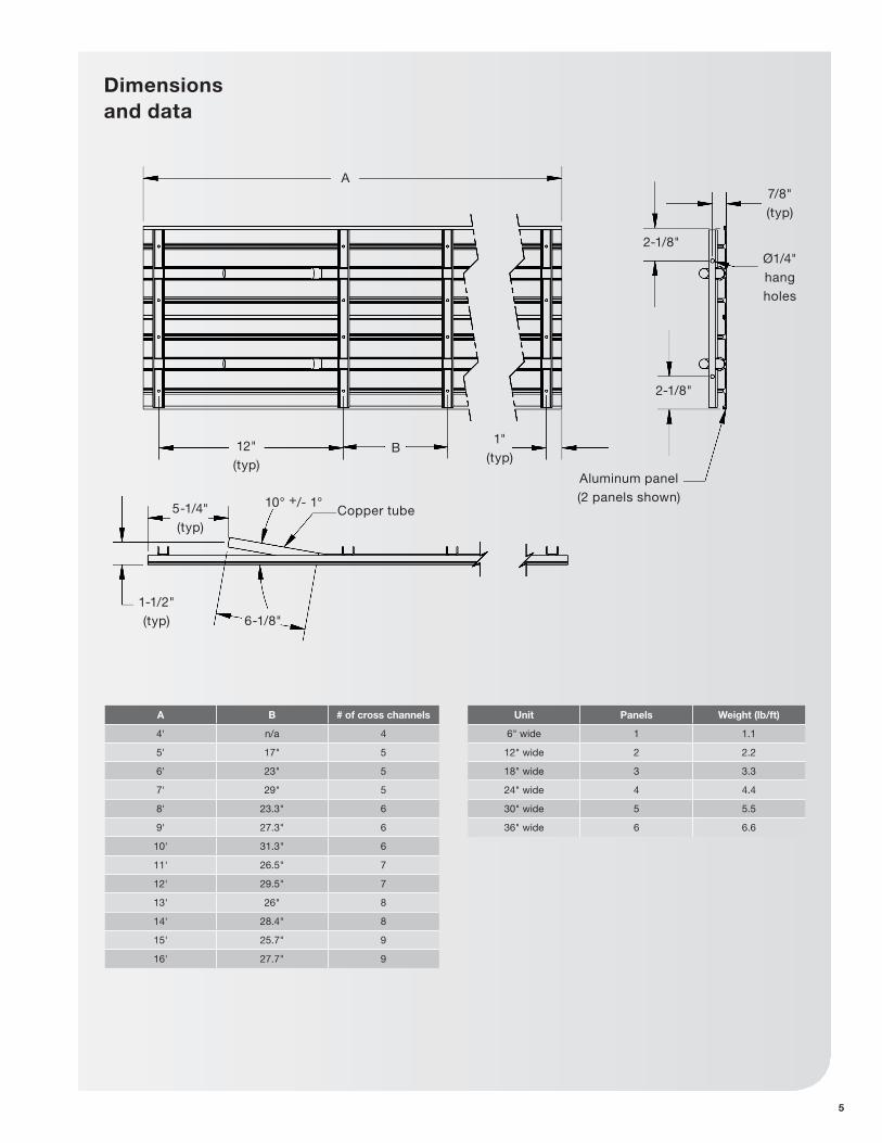
Dimensions and data
A
B12" (typ)
1" (typ)
2-1/8"
2-1/8"
7/8" (typ)
Ø1/4" hang holes
5-1/4" (typ)
1-1/2" (typ) 6-1/8"
10° +/- 1°Copper tube
Aluminum panel (2 panels shown)
Unit Panels Weight (lb/ft)
6" wide 1 1.1
12" wide 2 2.2
18" wide 3 3.3
24" wide 4 4.4
30" wide 5 5.5
36" wide 6 6.6
A B # of cross channels
4' n/a 4
5' 17" 5
6' 23" 5
7' 29" 5
8' 23.3" 6
9' 27.3" 6
10' 31.3" 6
11' 26.5" 7
12' 29.5" 7
13' 26" 8
14' 28.4" 8
15' 25.7" 9
16' 27.7" 9

Handling and installation
6
Improper mounting could result in the unit falling from its position, causing personal injury or even death.
After mounting the panel, it is then ready for the water service connections. At this time it should be verified that the proper types of services are actually provided to the unit. On those units requiring chilled water and/or hot water, the proper line size and water temperature should be available to the unit.
Linear Radiant Ceiling Panels should be transported vertically to prevent damage.
Do not transport panels horizontally. This could result in damage to the panel.
InstallationWhen installing radiant panels, you should have both the mechanical piping plan and the radiant ceiling panel shop drawing. Before starting with the installation, please familiarize yourself with the panels and their location by reviewing both drawings. All panels will arrive on site cut to the length given to the manufacturer and with expansion allowance.
All tubing used in the Zehnder Rittling Linear Radiant Ceiling Panels is 1/2" nominal copper tube (0.625" OD). Standard size fittings work easily with the Zehnder Rittling products. The panel tubing ends should be lifted up to approximately a 45 degree angle for attachment of U-bends or interconnecting flex connectors. The return bends, and if possible, the flexible interconnects should be installed at ground level. Be careful not to crimp tubing, as performance will be compromised. All copper tube connections require soldering or brazing to ensure a leak free system. Install copper connections first to tubing pass that is closest to perimeter wall. Circuiting of multiple panels should be done in a serpentine manner to ensure even flow over entire length of zone. Individual serpentine panel coils connected in series is unacceptable for multiple panel zones.
Use a heat pad between radiant ceiling panel and copper tube when making solder connection. Excessive heat can damage the paint finish.
While all equipment is designed for durability and fabricated with heavy gauge materials and may present a robust appearance, great care must be taken to assure that no undue force is applied to the piping, connection or aluminum surface during handling. Gloves should be worn when handling finished, painted panels and should never be set down on unclean, hard surfaces. Perspiration or grease from an ungloved hand can potentially leave a mark on the panel. Failure to follow these instructions may lead to scratching or gouging of the finished surface.
Although Zehnder Rittling does not become involved with the design and selection of support methods and/or components, it should be recognized that unacceptable operating characteristics and/or performance may result from poorly implemented unit support. Additionally, proper clearance must be provided for service and removal of the equipment.
Figure 1

7
Handling and installation
All radiant panels shall run continuously from wall to wall. Field trim to length as required, allowing adequate room for expansion after installation, generally 1/2" per panel. Allow 1/4" on either side of each panel in series to allow for expansion. Protect the finished surface before cutting. Using a circular saw with a carbide tipped blade or a jigsaw with an aluminum cutting blade, cut the panel. All radiant panels should be installed by workers wearing clean gloves to ensure a dirt-free
surface. When installing in a t-bar ceiling, ensure that the female edge (Figure 1) of the radiant panel is positioned toward the exterior wall. Lift the panel into place, making sure there is a 1/4" spacing left at both ends of the panel for expansion. Attach at least one wire tie from each cross brace to an anchor point found in the ceiling above the panel. Upon completion of all solder joints, the system should be pressure tested with water in accordance with the project specifications. An insulation blanket, usually 1" thick 1 pound density, should
cover the entire back of the panel. Cut the blanket to pass around the interconnecting piping and suspension wires. Make sure that each insulation blanket butts up tightly with the adjoining blanket. Do not place insulation blanket over lighting fixtures. Interconnecting piping does not require insulation and is not recommended by Zehnder Rittling to be insulated unless specifically required per specification.
Unpacking and preparation

8
Zehnder Rittling Linear Radiant Ceiling Panels are installed, as standard, into a ceiling grid.
Based upon the size of the panel, there are a number of suspension points available for use. Suspension points reside on the support brackets located near the panel ends on all panels and on additional support brackets installed on panels over 48" in length.
Linear panels are offered in six nominal widths and thirteen nominal lengths.
Weight (lb)Panel Width (inches)
6 12 18 24 30 36
Panel length (feet)
4 7.5 15.0 22.4 29.9 37.4 44.9
5 9.4 18.7 28.1 37.4 46.8 56.1
6 11.0 21.9 32.9 43.9 54.9 65.8
7 12.6 25.2 37.8 50.4 62.9 75.5
8 14.5 28.9 43.4 57.8 72.3 86.8
9 16.1 32.2 48.2 64.3 80.4 96.5
10 17.7 35.4 53.1 70.8 88.5 106.2
11 19.6 39.1 58.7 78.3 97.8 117.4
12 21.2 42.4 63.6 84.7 105.9 127.1
13 23.1 46.1 69.2 92.2 115.3 138.3
14 24.7 49.4 74.0 98.7 123.4 148.1
15 26.5 53.1 79.6 106.2 132.7 159.3
16 28.2 56.3 84.5 112.7 140.8 169.0
Suggested # of suspension
points per
Panel Width (inches)
6 12 18 24 30 36
Panel length (feet)
4 4 4 4 4 8 8
5 4 4 6 6 8 8
6 4 4 6 6 8 8
7 4 4 6 6 8 10
8 4 4 8 8 12 12
9 4 4 8 8 12 12
10 4 4 8 8 12 12
11 6 6 8 10 12 12
12 6 6 8 10 12 12
13 8 8 8 12 12 16
14 8 8 8 12 12 16
15 8 8 10 12 14 16
16 8 8 10 12 14 16
Suspension points and weights
Suspension

9
Level modules
For proper function, Linear Radiant Ceiling Panels must be leveled both in the longitudinal direction and in the traverse direction.

10
Installed in perimeter t-bar ceiling
Use (2) wire hangers if panel is over 600 mm or 24".
Acoustic ceiling tile.
Zehnder Rittling Radiant Panel.
Perimeter wall.
Steel crossbrace.
Wall angle by division 9.
Insulation by mechanical contractor.
T-Bar by division 9.
Minimum of (1) wire hanger, supplied by others, on each crossbrace

11
Installed in interior t-bar ceiling
Zehnder Rittling Radiant Panel.
Steel crossbrace.
Insulation by mechanical contractor.
T-bar by division 9.
Minimum of (1) wire hanger, supplied by others, on each crossbrace
Acoustic ceiling tile.
Use (2) wire hangers if panel is over 600 mm or 24".

12
Sloped install in t-bar ceiling
Perimeter wall.
Zehnder Rittling Radiant Panel.
Wall angle custom made to required angle by division 9.
Insulation by mechanical contractor.
Minimum of (1) wire hanger, supplied by others, on each crossbrace
Angle custom made to required angle by division 9. To be fastened to t-bar.
T-bar ceiling.

13
Sloped install in t-bar ceiling with corner
Zehnder Rittling Radiant Panel.
T-bar ceiling.
Wall angle custom made to required angle by division 9.
Insulation by mechanical contractor.
Angle custom made to required angle by division 9. To be fastened to t-bar.
Minimum of (1) wire hanger, supplied by others, on each crossbrace
Perimeter wall.
Mitered corner.

14
Installed at perimeter wall in drywall ceiling
Perimeter wall.
Zehnder Rittling Radiant Panel.
Wall angle by division 9.
Insulation by mechanical contractor.
T-bar by division 9.
Steel crossbrace.
Use (2) wire hangers if panel is over 600 mm or 24".
Minimum of (1) wire hanger, supplied by others, on each crossbrace.
Drywall ceiling.
Note:
nn Access to supply, return and interconnection between panels will be required.

15
Installed in drywall ceiling
Zehnder Rittling Radiant Panel.
Drywall ceiling.
Use (2) wire hangers if panel is over 600 mm or 24".
Insulation by mechanical contractor.
Note:
nn Access to supply, return and interconnection between panels will be required.
T-bar by division 9.
Steel crossbrace.
Minimum of (1) wire hanger, supplied by others, on each crossbrace

16
Recessed install in drywall ceiling
Zehnder Rittling Radiant Panel.
12 mm (0.5").
Insulation by mechanical contractor.
J-Molding, by others, for capping drywall exposed edges.
Steel crossbrace.
Framing by responsible trade.
Note:
nn Access to supply, return and interconnection between panels will be required.
Use (2) wire hangers if panel is over 600 mm or 24".
Minimum of (1) wire hanger, supplied by others, on each crossbrace.
Drywall ceiling.

17
Installed behind bulkhead
Zehnder Rittling Radiant Panel.
Height of ceiling may vary.
Angle by division 9.
Use (2) wire hangers if panel is over 600 mm or 24".
Insulation by mechanical contractor.
Note:
nn Access through bulkhead required for connection.
Steel crossbrace.
Drop bulkhead.
Angle recessed from bulkhead a minimum of 13 mm. Never install flush with bulkhead.
Perimeter wall.
Minimum of (1) wire hanger, supplied by others, on each crossbrace.

18
Installed behind bulkhead with slot diffuser
Zehnder Rittling Radiant Panel.
Insulation by mechanical contractor.
Linear slot diffuser by others.
Drop bulkhead.
Access required for connecting panels.
Perimeter wall.
Steel crossbrace.
Angle by division 9.
Use (2) wire hangers if panel is over 600 mm or 24".
Minimum of (1) wire hanger, supplied by others, on each crossbrace.
Height of ceiling may vary.

19
Cooling/heating system
Prior to the water system start-up and balancing, the chilled/hot water system should be thoroughly flushed to clean out dirt and debris which may have accumulated in the piping during construction. During this procedure, all panel service
valves must be in the closed position. This will prevent any foreign material from entering the panel’s piping and clogging valves and metering devices. Strainers should be installed in the piping mains to prevent this material from entering the units during normal operation.
During system filling, air venting from the panel is accomplished through the main system air vents.
Water system balancing
A complete knowledge of the hydronic system, including its components and controls, is essential to proper water system balancing and should only be completed by a qualified expert. The system must be complete, and all components must be in operating condition before beginning the water system balancing procedures.
Each hydronic system has different operating conditions depending on the devices and controls installed for the particular application. The actual balancing technique may vary from one system to another.
After the proper system operation is established, the appropriate operating conditions such as water temperatures, flow rates and pressure drops should be recorded for future reference.
Inspect the entire system for potential air traps and independently vent those areas as required. In addition, some systems may require repeated venting over time to fully eliminate air in the system.
It is recommended that balancing of the system should be done during the winter when full flow will be realized. Before and during water system balancing, conditions may exist due to incorrect system pressures which may result in noticeable water noise or undesired valve operation. After the entire system is balanced, these conditions will not exist on properly designed systems. If any of these conditions persist, recheck the system for air that may not have been properly vented during start-up.
Water content Required concentration
Sulphate < 200 ppm
pH 7.0 – 8.5
Chlorides < 200 ppm
Nitrate < 100 ppm
Iron < 4.5 mg/L
Ammonia < 2.0 mg/L
Manganese < 0.1 mg/L
Dissolved solids < 1000 mg/L
Calcium carbonate hardness
300 – 500 ppm
Calcium carbonate alkalinity
300 – 500 ppm
Particulate quantity < 10 ppm
Particulate size 800 micron max
Water treatmentProper water treatment is a specialized industry and therefore it is recommended to consult an expert in this field to analyze the water for compliance with the water quality parameters listed below and to specify the appropriate water treatment program. The expert may recommend rust inhibitors, scaling preventative, antimicrobial growth agents or algae preventatives. Anti-freeze solutions, glycols, may also be used to lower the freezing point.
All Zehnder Rittling panels are constructed with copper tubes. It is the end user’s responsibility to ensure that any of the water delivery components are compatible with the treated water.
Failure to provide proper water quality will void the celing panel’s warranty.

20
Panel piping connections Linear circuitry
S
R
R
S
S
R
R
S
Odd pass circuitry
Even pass circuitry
Multiple panel circuitry odd pass
Multiple panel circuitry even pass
Connect the panels with flexible interconnectors.

21
Panel piping connections
Header circuitry
R S
Header system by mechanical contractor
(typ).
Interconnectors supplied by Zehnder Rittling (typ).
Multiple panel circuitry for longer zones
22
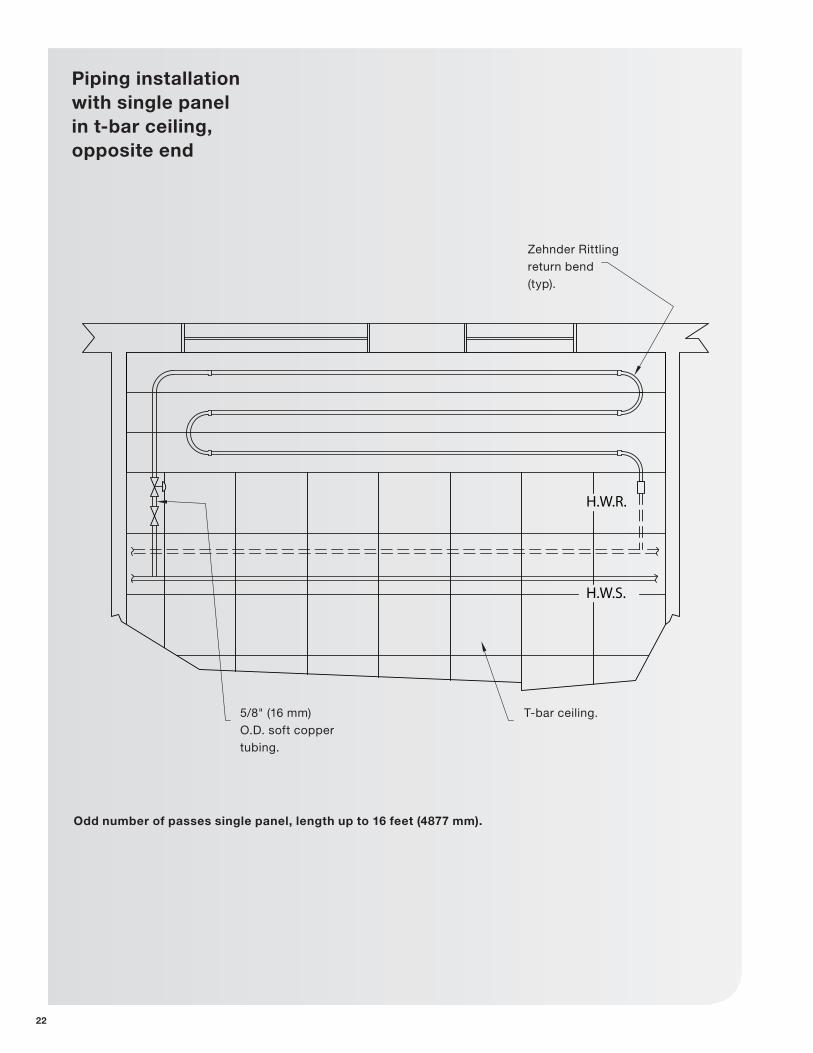
Piping installation with single panel in t-bar ceiling, opposite end
H.W.R.
H.W.S.
Odd number of passes single panel, length up to 16 feet (4877 mm).
Zehnder Rittling return bend (typ).
5/8" (16 mm) O.D. soft copper tubing.
T-bar ceiling.
23
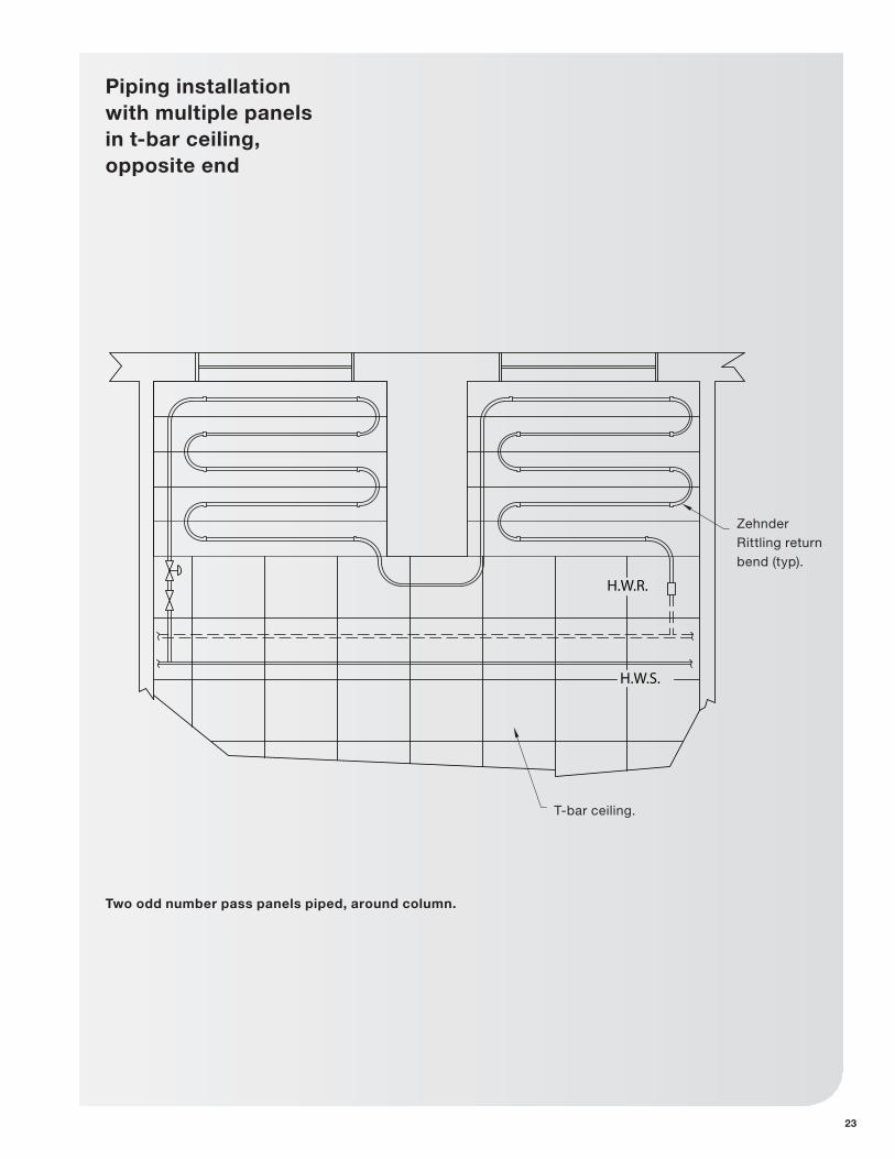
Piping installation with multiple panels in t-bar ceiling, opposite end
H.W.R.
H.W.S.
T-bar ceiling.
Zehnder Rittling return bend (typ).
Two odd number pass panels piped, around column.

24
Piping installation with column interference in t-bar ceiling, same end
H.W.R.
H.W.S.
Zehnder Rittling Radiant Panels positioned clear of perimeter columns. Even pass coiling shown.
5/8" (16 mm) soft copper.
Zehnder Rittling interconnectors (typ).
Zehnder Rittling return bends (typ).
T-bar ceiling.

25
Piping installation with column interference in t-bar ceiling, same end
H.W.R.
H.W.S.
5/8" (16 mm) soft copper.
5/8" (16 mm) O.D. soft copper for connecting panels by mechanical contractor (typ).
Zehnder Rittling interconnectors (typ).
Zehnder Rittling return bends (typ).
T-bar ceiling.
Zehnder Rittling Radiant Panels notched around perimeter columns. Even pass coiling shown.

Submittals and product literature detailing unit operation, controls and connections should be thoroughly reviewed before beginning the connection of the various cooling and/or heating mediums to the panels.
All shipped loose valves, hoses, and interconnectors should be installed as required and all service valves should be checked for proper operation.
After the module connections are completed, the system should be tested for leaks. Since some components are not designed to hold pressure with a gas, hydronic systems should be tested with water. Test pressure must not exceed 200 psig. Pressure testing should be completed prior to sheet rocking, finished floors, painting, caulking, etc.
All panels must be protected from freezing after initial filling with water. Even if the system is drained, panels may still hold enough water to cause damage when exposed to temperatures below freezing.
In the event that leaking or defective components are discovered, the Zehnder Rittling Sales Representative must be notified before any repairs are attempted. All leaks should be repaired before proceeding with the installation.
After fixing any leaks, air should be vented from the system by reintroducing water at 0.5 GPM or higher. The water temperature should be brought up gradually to the design temperature. The design water temperature drop will only be attained when building is under full load.
After system integrity has been established, the panels should be insulated in accordance with the project specifications. This is the responsibility of the installing or the insulation contractor if not already purchased and provided by Zehnder Rittling. Zehnder Rittling will not accept any charges associated with re-insulating panels if the installing contractor failed to establish system integrity prior to insulating.
26
Chilled/hot water connections
27
Start upEach zone of Zehnder Rittling radiant panels should be pressure tested for leaks as required in the specifications. All system piping should be thoroughly cleaned, flushed, drained and refilled before the radiant panels are connected into the sytem.
With boiler in operation and circulators on, set control valves to full flow position. Flow in excess of 0.5 GPM per circuit is required to remove air from tubing and interconnects on the panel. Gradually bring the sytem to design temperature. The actual temperature drop through the panel will only be achieved when building is under design load. Balancing the radiant ceiling system without calibrated balancing valves should be done during a cloudy day in the wintertime. After balancing, return the control valves to automatic operation.
Operation
nn Maximum temperature: 185 °F
nn Minimum temperature: 40 °F
nn Maximum pressure: 145 psi
nn Ensure air is removed from system at start-up and during operation.
MaintenanceMaintenance is minimal for this type of heating system. Keeping strainers clean is the only real required maintenance concerning the piping system. Any descaling of the piping system should be performed as in any other hydronic heating system. The panels are designed to last and should be resistant to any damage. However, if there is noticeable damage to any of the panels, the piping should be inspected for leaks and the panels should be checked to make sure they are securely fastened.
Start up, operation, maintenance and cleaning
CleaningThe surface of the panels is easily cleaned with an industrial vacuum to remove dirt and dust. If the panels can not be adequately cleaned in this manner, use a damp cloth or sponge and mild detergent. Avoid abrasive cleaners on the painted surface. Frequent changing of the rinse water will help minimize streaking. All cleaning should be performed with thermostats in the off position and panels at room temperature. This will also help avoid streaking.
Operation

28
Factory replacement parts should be used wherever possible to maintain unit performance and its normal operating characteristics.
Replacement parts may be purchased through the local Zehnder Rittling Sales Representative.
Receiving and inspectionnn Panel received undamaged
nn Panel received complete as ordered
Handling and installationnn Panel protected from dirt and foreign matter
nn Panel mounted level and square
nn Proper access is provided for panel and accessories
Equipment start-up checklist
Replacement parts Contact the local Sales representative or factory before attempting any unit modifications. Any modifications not authorized by the factory could result in personnel injury, damage to the unit, and will void the manufacturer’s warranty.
When ordering parts, the following information should be supplied to ensure proper part identification:
nn Complete unit model number
nn Complete part description including any identifying numbers on the part
nn Proper chilled/hot water line sizes to panel
nn All services to panel in code compliance
nn 1/4" gap left around each panel for expansion
nn Insulation is in place
Cooling/heating connectionsnn Connect field piping to panel
nn Pressure test all piping for leaks
nn All air vented from system
On warranty replacements, it is often necessary to return the faulty component to receive credit. Contact the local Sales Representative who will get authorization from the factory including an RGA (Returned Goods Authorization) to be used when sending components back for inspection. Any returned components sent back to the factory without the proper RGA attached will cancel any outstanding credit.
Unit start-upnn General visual inspection and system inspection
nn Close all panel isolation valves
nn Flush water systems
nn After system has been flushed, ensure all isolation valves are open
Maintenance


Zehnder Rittling · 100 Rittling Boulevard · Buffalo, NY USA 14220T 844-934-6337 (844-ZEHNDER) · F [email protected] · www.zehnder-rittling.com
© Z
ehnd
er R
ittlin
g M
arch
201
5, E
nglis
h, s
ubje
ct t
o c
hang
e w
itho
ut n
otic
e