Zeeman ratchets: pure spin current generation in - IOPscience
24
OPEN ACCESS Zeeman ratchets: pure spin current generation in mesoscopic conductors with non-uniform magnetic fields To cite this article: Matthias Scheid et al 2007 New J. Phys. 9 401 View the article online for updates and enhancements. You may also like Elymat Measurement of Intentionally Contaminated and Dry Etched Wafers J. Wittmann, W. Bergholz and H. Hoffmann - Axial Magnetic Effect and Chiral Vortical Effect with free lattice chiral fermions P V Buividovich - Orbital-unrelaxed Lagrangian density matrices for periodic systems at the local MP2 level D Usvyat and M Schütz - Recent citations Quantum network approach to spin interferometry driven by Abelian and non- Abelian fields A. Hijano et al - Quantum spin Hall phase in honeycomb nanoribbons with two different atoms: edge shape effect to bulk-edge correspondence Kenji Kondo and Ren Ito - Unified quaternionic description of charge and spin transport and intrinsic nonlinearity of spin currents T. P. Pareek - This content was downloaded from IP address 46.166.80.174 on 11/12/2021 at 18:35
Transcript of Zeeman ratchets: pure spin current generation in - IOPscience
OPEN ACCESS
Zeeman ratchets: pure spin current generation inmesoscopic conductors with non-uniform magneticfieldsTo cite this article: Matthias Scheid et al 2007 New J. Phys. 9 401
View the article online for updates and enhancements.
You may also likeElymat Measurement of IntentionallyContaminated and Dry Etched WafersJ. Wittmann, W. Bergholz and H.Hoffmann
-
Axial Magnetic Effect and Chiral VorticalEffect with free lattice chiral fermionsP V Buividovich
-
Orbital-unrelaxed Lagrangian densitymatrices for periodic systems at the localMP2 levelD Usvyat and M Schütz
-
Recent citationsQuantum network approach to spininterferometry driven by Abelian and non-Abelian fieldsA. Hijano et al
-
Quantum spin Hall phase in honeycombnanoribbons with two different atoms:edge shape effect to bulk-edgecorrespondenceKenji Kondo and Ren Ito
-
Unified quaternionic description of chargeand spin transport and intrinsic nonlinearityof spin currentsT. P. Pareek
-
This content was downloaded from IP address 46.166.80.174 on 11/12/2021 at 18:35
T h e o p e n – a c c e s s j o u r n a l f o r p h y s i c s
New Journal of Physics
Zeeman ratchets: pure spin current generationin mesoscopic conductors with non-uniformmagnetic fields
Matthias Scheid 1,3, Dario Bercioux 1,2 and Klaus Richter 1
1 Institut für Theoretische Physik, Universität Regensburg, D-93040Regensburg, Germany2 Physikalisches Institut, Albert-Ludwigs-Universität,D-79104 Freiburg, GermanyE-mail:[email protected]@physik.uni-freiburg.de
New Journal of Physics 9 (2007) 401Received 16 July 2007Published 6 November 2007Online athttp://www.njp.org/doi:10.1088/1367-2630/9/11/401
Abstract. We consider the possibility to employ a quantum wire realized ina two-dimensional electron gas (2DEG) as a spin ratchet. We show that a netspin current without accompanying net charge transport can be induced in thenonlinear regime by an unbiased external driving via an ac voltage appliedbetween the contacts at the ends of the quantum wire. To achieve this, we makeuse of the coupling of the electron spin to inhomogeneous magnetic fields createdby ferromagnetic stripes patterned on the semiconductor heterostructure thatharbors the 2DEG. Using recursive Green function techniques, we numericallystudy two different set-ups, consisting of one and two ferromagnetic stripes,respectively.
3 Author to whom any correspondence should be addressed.
New Journal of Physics 9 (2007) 401 PII: S1367-2630(07)55257-21367-2630/07/010401+23$30.00 © IOP Publishing Ltd and Deutsche Physikalische Gesellschaft
2
Contents
1. Introduction 22. Model and formalism 43. Set-up A: two ferromagnetic stripes with longitudinal magnitization 7
3.1. DC transport. . . . . . . . . . . . . . . . . . . . . . . . . . . . . . . . . . . . 83.2. AC transport. . . . . . . . . . . . . . . . . . . . . . . . . . . . . . . . . . . . 10
4. Set-up B: a single ferromagnetic stripe with transverse magnetization 124.1. DC transport. . . . . . . . . . . . . . . . . . . . . . . . . . . . . . . . . . . . 134.2. AC transport. . . . . . . . . . . . . . . . . . . . . . . . . . . . . . . . . . . . 14
5. Conclusions and outlook 16Acknowledgments 18Appendix A. Calculation of the spin current in the Landauer–Büttiker formalism 18Appendix B. Derivation of symmetry relations for spin-dependent Landauer
transport at finite bias 21References 22
1. Introduction
Spintronicsas an emerging field of physics has attracted considerable attention in recent yearsand has developed into various inter-related branches covered in this focus issue. Spintronicsis devoted to employing the spin degree of freedom for information storage and as anothermeans for extending the functionality of electronic systems. Semiconductor spintronics, as onesubfield, is guided by the idea of combining concepts of spin electronics with the establishedtechniques and advantages of semiconductor physics and nanostructures. Up to now, their prop-erties used mainly rely on the charge degree of freedom alone. Many ideas for employing spin-polarized currents have been put forward since the seminal proposal by Datta and Das for a spintransistor [1] based on spin precession controlled by an external electric field through spin–orbit(SO) coupling [2]. These proposals usually require spin injection, more generally, the creationof spin-polarized particles in these materials. Spin injection from a ferromagnetic metal sourceinto semiconductors is hindered by a fundamental obstacle originating from the conductivitymismatch between these materials [3]. Though this problem may be partially circumvented,for instance at low temperatures by tailoring dilute-magnetic-semiconductor/semiconductorinterfaces [4, 5] enabling considerable spin-polarization ratios of the order of 90% [4], buildingall-semiconductor sources of spin-polarized electrons is still a challenge.
Alternatively, several techniques to intrinsically create spin currents in non-magneticsystems have been put forward: non-equilibrium spin-polarized currents have been createdin two-dimensional electron gases (2DEGs) realized in zinc-blende-based heterostructures bymeans of optical pumping [6]. The irradiation of the 2DEG with circularly polarized lightresults in a spin photocurrent caused by the non-uniform distribution of the photoexcitedcarriers ink-space owing to optical selection rules and energy and momentum conservation.The recently proposed intrinsic spin-Hall effect inp-doped [7] bulk systems and in 2DEGs [8]offers the principle possibility for spin current generation and manipulation in high mobility
New Journal of Physics 9 (2007) 401 (http://www.njp.org/)
3
semiconducting systems. The combined effect of an applied electric field and the torque inducedby SO coupling tilts the spins out of the 2DEG plane. This leads to spin accumulation atboth sides of the sample in the direction perpendicular to the applied electric field. Spin-Halleffects have been observed experimentally both in semiconducting systems by optical detectiontechniques [9]–[11] and in metallic systems with an all-electrical set-up [12, 13].
In the context of mesoscopic physics, further concepts such as adiabatic spinpumping [14]–[16] and coherent spin ratchets [17, 18] have been proposed for generatingspin-polarized currents. This can be achieved by exploiting the magnetic properties of thesemiconducting material, i.e. intrinsic SO interaction or the Zeeman coupling to externalmagnetic fields.
Adiabatic quantum pumping involves the generation of a directed current in the absenceof a bias voltage by periodic modulations of two or more system parameters, such as, e.g. theshape of the system or a magnetic field [19]. The spin analog of the charge quantum pumpcan be achieved through an external magnetic field [15] or SO interaction [16] in order tofilter the pumped current. For the case of an external magnetic field, it has been experimentallyconfirmed that under specific circumstances a spin current can be extracted from spin-dependentconductance fluctuations without accompanying net charge flow [20].
Ratchets[21] are generally systems with broken inversion (left/right) symmetry thatgenerate directed net (particle) currents upon external ac driving in the absence of a net(time-averaged) bias potential. Thereby they have much in common with current rectifiers,though there are differences, in particular in the dissipative case [21]. The theoretical conceptof ratchets, originally introduced for classical dynamics, was later extended to the quantumdissipative regime [22]. As a main feature, which distinguishes them also from rectifiers in theusual sense, quantum ratchets exhibit current reversal upon changing, e.g. the temperature orenergy. Such quantum ratchets were experimentally realized in semiconductor heterostructuresby demonstrating directed charge flow in a chain of asymmetric ballistic electron cavitiesin the low-temperature regime, where the dynamics was close to coherent [23]. In this andfurther experimental investigations [24] also the charge current reversal phenomenon has beendemonstrated.
Very recently, we have proposed the generalization of the ratchet mechanism, extensivelyexplored for particle motion, to generate directed spin currents. Spin ratchets require a couplingto the electron spin which, e.g. can be provided via SO interaction or external (non-uniform)magnetic fields. In Scheidet al [17], spin–orbit ratchetshave been considered in the coherentregime. There, a proof of principle for a net ratchet spin current (in the absence of an averagecharge current) has been given and confirmed by numerical calculations for experimentallyaccessible parameters for GaAs-based heterostructures.
In the present paper, we further investigate the possibility of employingZeeman ratchetsfor spin current generation, i.e. by considering mesoscopic conductors with a spatially varyingZeeman term and subject to an ac bias. In the simplest case of one-dimensional (1D) motion,and assuming preserved spin states, spin-up and spin-down electrons will experience a Zeemanterm,±(g∗/2) µB B(x), whereB(x) is the external non-uniform magnetic field,g∗ the effectivegyroscopic factor andµB the Bohr magneton. IfB(x) 6= B(−x), then the different spin speciesexperience opposite asymmetric Zeeman ratchet potentials. In close analogy to the particleratchet mechanism described above, the different spins are expected to be predominantlydriven into opposite directions upon external driving, resulting in a spin-polarized current. Thismechanism has been studied and confirmed by Scheidet al [18].
New Journal of Physics 9 (2007) 401 (http://www.njp.org/)
4
yx
z
a
W
d aa
bW
0y
(a) (b)
e
cc ce
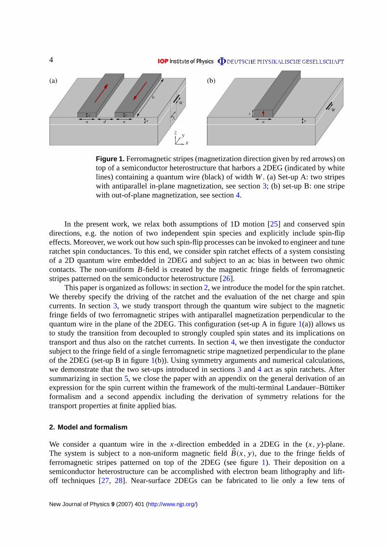
Figure 1. Ferromagnetic stripes (magnetization direction given by red arrows) ontop of a semiconductor heterostructure that harbors a 2DEG (indicated by whitelines) containing a quantum wire (black) of widthW. (a) Set-up A: two stripeswith antiparallel in-plane magnetization, see section3; (b) set-up B: one stripewith out-of-plane magnetization, see section4.
In the present work, we relax both assumptions of 1D motion [25] and conserved spindirections, e.g. the notion of two independent spin species and explicitly include spin-flipeffects. Moreover, we work out how such spin-flip processes can be invoked to engineer and tuneratchet spin conductances. To this end, we consider spin ratchet effects of a system consistingof a 2D quantum wire embedded in 2DEG and subject to an ac bias in between two ohmiccontacts. The non-uniformB-field is created by the magnetic fringe fields of ferromagneticstripes patterned on the semiconductor heterostructure [26].
This paper is organized as follows: in section2, we introduce the model for the spin ratchet.We thereby specify the driving of the ratchet and the evaluation of the net charge and spincurrents. In section3, we study transport through the quantum wire subject to the magneticfringe fields of two ferromagnetic stripes with antiparallel magnetization perpendicular to thequantum wire in the plane of the 2DEG. This configuration (set-up A in figure1(a)) allows usto study the transition from decoupled to strongly coupled spin states and its implications ontransport and thus also on the ratchet currents. In section4, we then investigate the conductorsubject to the fringe field of a single ferromagnetic stripe magnetized perpendicular to the planeof the 2DEG (set-up B in figure1(b)). Using symmetry arguments and numerical calculations,we demonstrate that the two set-ups introduced in sections3 and4 act as spin ratchets. Aftersummarizing in section5, we close the paper with an appendix on the general derivation of anexpression for the spin current within the framework of the multi-terminal Landauer–Büttikerformalism and a second appendix including the derivation of symmetry relations for thetransport properties at finite applied bias.
2. Model and formalism
We consider a quantum wire in thex-direction embedded in a 2DEG in the (x, y)-plane.The system is subject to a non-uniform magnetic fieldEB(x, y), due to the fringe fields offerromagnetic stripes patterned on top of the 2DEG (see figure1). Their deposition on asemiconductor heterostructure can be accomplished with electron beam lithography and lift-off techniques [27, 28]. Near-surface 2DEGs can be fabricated to lie only a few tens of
New Journal of Physics 9 (2007) 401 (http://www.njp.org/)
5
nanometres beneath the surface [28], thereby achieving magnetic field values of up to 0.5 T withthin ferromagnetic films [29]. The magnetic fringe field of a ferromagnet with homogeneousmagnetizationEM is given by [30]
EB(Er )=−µ0
4πE∇
∮S
da′EM × u(Er ′)
|Er − Er ′|, (2.1)
where the integration runs over the surfaceS of the ferromagnetic stripe, andu(Er ′) is the unitvector normal to the surface of the stripe at positionEr ′. Accordingly, the corresponding vectorpotential in the Coulomb gauge,E∇ · EA= 0, is given by [30]
EA(Er )=µ0
4π
∮S
da′EM × u(Er ′)
|Er − Er ′|. (2.2)
We model the wire, where electron transport is assumed to be phase coherent, by thesingle-particle Hamiltonian
H0=5x(x, y)2 +5y(x, y)2
2m∗+
g∗µB
2EB(x, y) · Eσ + V(y), (2.3)
where g∗ is the effective gyroscopic factor,m∗ the effective electron mass,µB the Bohrmagneton andEσ the vector of the Pauli matrices. The termV(y) denotes the lateral confiningpotential defining the quantum wire. Orbital effects due to the magnetic field are accounted forby the vector potentialEA(x, y) in E5(x, y)= Ep−eEA(x, y). Spin effects in transport throughthe wire enter via the Zeeman term(g∗µB/2) EB · Eσ coupling the spin degree of freedom to theexternal magnetic field. For a proper treatment of the spin evolution, the inclusion of the fullmagnetic field profile is mandatory [31]; disregarding [32] one of the magnetic field componentsBi may lead to an oversimplification of the problem.
To obtain a significant spin ratchet effect materials with a largeg∗ factor are most suitable.In this respect dilute magnetic semiconductors (DMS) represent a promising class of materials.Recent measurements have shown values ofg∗ >100 [33], where in addition to the intrinsicg-factor, an additional contribution tog∗ appears, owing to exchange coupling among theelectron spins and the magnetic ions present in the DMS [34]. These materials with a largeg∗
factor can also exhibit large SO coupling values. The working principle of a spin ratchet basedon SO coupling has been already investigated in Scheidet al [17]. As one result of this studya spin-ratchet effect can only occur if there exists the possibility to mix different transversechannels of the wire. This can only happen when more than one open channel is taking partin the transport and electrostatic barriers induce this mixing of different bands. As we willshow below, the spin-ratchet effect created by the setup presented in this paper does not relyon this condition and is already present when only the first conducting channel is opened. Dueto this fact and the absence of any electrostatic barriers responsible for the mixing of differentsubbands, we disregard here the SO coupling and focus on the effects due to the presence of themagnetic stripes.
In the present work where we consider disorder-free ballistic motion, we refer tononmagnetic high-mobility semiconductors. To be definite, we chose throughout the paperparameters for InAs 2DEGs with typical values ofm∗ = 0.024m0 [35], wherem0 is the freeelectron mass, and|g∗| = 15. InAs is well suited due to its largeg∗ factor and the property thatInAs 2DEGs can be fabricated close to the surface where the magnetic stripes are located. Weassume that the stripes possess a magnetizationµ0M = 3T.
New Journal of Physics 9 (2007) 401 (http://www.njp.org/)
6
The charge currentIC through the wire is evaluated within the Landauer approach. Forcoherent transport in a two-terminal device the current can be expressed as
IC=−e
h
∫∞
0dE
[f (E;µL)− f (E;µR)
]T(E) (2.4)
in terms of the quantum probabilityT(E) for electrons with energyE to be transmitted from thelead at higher to the lead at lower potential. In equation (2.4), f (E;µL/R) is the Fermi functionfor the left/right lead with chemical potentialµL/R.
The spin currentIS(x) passing a cross-section (x = const.) is given, for a wavefunction9(x, y), by
IS(x)=
∫dy 9∗(x, y) JS9(x, y).
Here, we use the most common definition [36] of the spin current operatorJS which, withrespect to an arbitrary quantization axisu, reads
JS=h
2
h
2m∗i
(Eσ · u
) (−→∂∂x−
←−∂
∂x
), (2.5)
inside the leads. The partial derivatives in (2.5) act on expressions to their right and left(indicated by the arrows).
Contrary to the charge current that obeys a continuity equation, the spin current can takedifferent values if evaluated in the left or in the right lead. This usually happens in systems wherethe Hamiltonian does not commute with the Pauli matricesEσ giving rise to a torque inside thescattering region [37], which can change the spin state of the electrons. For this reason we willexplicitly label the lead, where we compute the spin current. Although there is some ambiguityin the choice of the spin current operator [38], here we evaluate the spin current inside themagnetic field free leads, where a torque term in the continuity equation for spin is absent.Therefore, the spin current inside the leads is a well-defined quantity, which can be measured inprinciple. As derived in appendixA (equationA.9) the corresponding spin current in the rightlead reads
IS=1
4π
∫∞
0dE
[f (E;µL)− f (E;µR)
]TS(E), (2.6)
with the spin transmission probability defined as
TS(E)=∑σ=±1
[T+,σ (E)− T−,σ (E)
]. (2.7)
HereTσ ′,σ is the probability for an electron with initial spin stateσ to be transmitted from theleft lead into the spin stateσ ′ inside the right lead, see equation (A.7) in appendixA. To obtainthe corresponding spin current in the left lead one has to replaceTσ ′,σ (E) in equation (2.7) bythe corresponding probabilitiesT ′σ ′,σ (E) for transmission from the right to the left lead.
Ordinary particle ratchets give rise to a net drift motion of particles in one preferentialdirection upon ac driving without net bias (rocking ratchet). Below we will generalize thisconcept to induce spin-dependent ratchet currents correspondingly. The ac driving can beconsidered as adiabatic, since the timescales for the variation of an external bias potentialare long compared to the relevant timescales for charge transmission through the device. Fora proof of principle, we assume an adiabatic unbiased square-wave driving with periodt0.
New Journal of Physics 9 (2007) 401 (http://www.njp.org/)
7
The system is periodically switched between two rocking conditions, labeled by bias±U0
(U0 > 0). The electro-chemical potentialµL/R of the left/right reservoir is changed periodicallyin time according to
µL/R(t)=
{εF±U0/2, for 06 t < t0/2,
εF∓U0/2, for t0/26 t < t0,(2.8)
i.e. µL/R(t)= µL/R(t + t0). In the adiabatic limit considered, the system is assumed to be in asteady state between the switching events. Then the ratchet charge and spin currents inside thewire are obtained upon averaging equations (2.4) and (2.6) between the two rocking situations
〈IC(εF,U0)〉 =12 [ IC(εF, +U0) + IC(εF,−U0)] =− e
2h
∫∞
0 dE1 f (E; εF,U0)1T(E;U0) , (2.9a)
〈IS(εF,U0)〉 =12 [ IS(εF, +U0) + IS(εF,−U0)] = 1
8π
∫∞
0 dE1 f (E; εF,U0)1TS(E;U0) , (2.9b)
where
1 f (E; εF,U0)= f (E; εF +U0/2)− f (E; εF−U0/2),
1T(E;U0)= T(E;+U0)− T(E;−U0), (2.10)
1TS(E;U0)= TS(E;+U0)− TS(E;−U0).
An extension to an adiabatic harmonic driving is straightforward.In linear response, the ratchet spin current〈IS〉, equation (2.9b), vanishes because
1TS(E;U0= 0)= 0, see equation (2.10). Hence, we must consider the nonlinear regimeto obtain a finite net spin current. Since we consider nonlinear transport ignoring inelasticprocesses, we can write the currents equations (2.4) and (2.6) as energy integrals over thetransmission. To model a finite voltage drop across the two leads, we add the term
HU =Ug(x, y;U ), (2.11)
to the Hamiltonian (2.3), where for the square wave driving considered here,U takes thevalues±U0 respectively. Here the functiong(x, y;U ) describes the spatial distribution of theelectrostatic potential inside the mesoscopic system and is generally obtained through a self-consistent solution of the many-particle Schrödinger equation and the Poisson equation [39, 40].However, here we employ heuristic models forg(x, y;U ), assuming that the voltage primarilydrops in regions, where the magnetic field strongly varies spatially. This model is based on thefact that the corresponding Zeeman term acts as an effective potential barrier, and takes intoaccount that a more rapid potential variation leads to enhanced wave reflection and hence to asteeper local voltage drop [41] (details will be given in the following sections).
In order to numerically evaluate the transport properties of the system, the stationarySchrödinger equation(H− E)8(Er )= 0 is discretized on a square lattice, yielding a tight-binding representation ofH. This is then used to calculate the elements of the scattering matrixof the system via lattice Green’s functions and a recursive Green’s function algorithm [42].
3. Set-up A: two ferromagnetic stripes with longitudinal magnitization
In this section, we investigate the spin-dependent transport properties (and thereby also theoperability as a ratchet) of a quantum wire in the plane of the 2DEG subject to the magneticfield of two stripes with opposite, longitudinal in-plane magnetizations,EM =±M y, arrangedperpendicular to the wire. This set-up A is shown in figure1(a). The Hamiltonian of the system
New Journal of Physics 9 (2007) 401 (http://www.njp.org/)
8
is given by equation (2.3) with Ay = 0 (in the Coulomb gauge), i.e.5y = py. For the followinganalysis we chose a confinement potentialV(y) such that the wire of widthW is displaced by ashift y0 with respect to the symmetric configuration, see figure1.
For sufficiently narrow wires(W� b) and small displacement (y0� b), the energy scalesof the magnetic field contributions toH0 in equation (2.3) containingEB and EA are much smallerthan differences between energy levelsEm− En of different transversal modes|m〉 and |n〉.Therefore, transitions between different transversal modes are strongly suppressed, and weconsider the case of only one open mode. Higher modes|n〉 mimic the behavior of the firstmode up to an energy offsetEn− E1.
Evaluating equation (2.1) for the combined magnetic field of two stripes centeredaround(x = 0, y= 0), set-up A, we obtain the following symmetry properties for theB-fieldcomponents of this configuration:
Bx(x,−y, z)=−Bx(x, y, z), (3.1a)
By(x,−y, z)= By(x, y, z), (3.1b)
Bz(x,−y, z)=−Bz(x, y, z). (3.1c)
In particular, equations (3.1a) and (3.1c) imply vanishing magnetic field componentsBx andBz for y= 0. Therefore, we usey as the spin quantization axis for the considerations below.Those symmetries also have an important implication for the spin dynamics of the system. Fora confinement potential that is symmetric upon reflection at the(x, z)-plane,V(−y)= V(y),as realized for a symmetric confinement centered aroundy0= 0, spin-up and spin-downeigenstates within the same transversal moden are decoupled. The relevant matrix element〈n, σ | Eσ · EB(x, y) |n,−σ 〉, responsible for the spin mixing, vanishes,∫
∞
−∞
dy |χn(y)|2[Bz(x, y)− iσ Bx(x, y)
]= 0 , (3.2)
since the integrand is an odd function ofy due to equations (3.1a) and (3.1c) and the fact thattransversal modes obeyχn(−y)= (−1)n−1χn(y). However, for finite values ofy0, the coupling(3.2) does not vanish anymore, and spin flips can arise with a significant effect on electrontransport, as we will demonstrate in the next section.
3.1. DC transport
Before evaluating the average charge current (2.9a) and spin ratchet current (2.9b), it isinstructive to analyze the dc transport properties of set-up A. To this end we chose as realisticparameters for the geometry (see figure1(a))W = 120 nm,a= 600 nm,b= 2µm (thusW/b=0.06),c= 200 nm,d = 600 nm ande= 100 nm. For this parameter set andy0� b the magneticfield componentBy(x, y) is approximately constant iny-direction, i.e.By(x, y)≈ By(x). Itpossesses a much larger maximum value than the other componentsBx andBz. In figure2, weshow thex-dependence of the overall magnetic fringe field of the two-stripe set-up A for fixedy= 200 nm.
Figure 3 shows the total transmissionT(E) in linear response (U0→ 0) for energieswithin the first transversal subband for different values ofy0. For y0= 0, the spin eigenstatesdecouple owing to equation (3.2). The energy where the first transversal mode opens is shiftedto E ≈ E1 +UB due to the Zeeman barrier of heightUB = g∗µB max[By(x, y= 0)]/2 present in
New Journal of Physics 9 (2007) 401 (http://www.njp.org/)
9
0–2 µm 2 µmx
–0.01
0
0.01
B [
µ 0M]
1 2 4 53
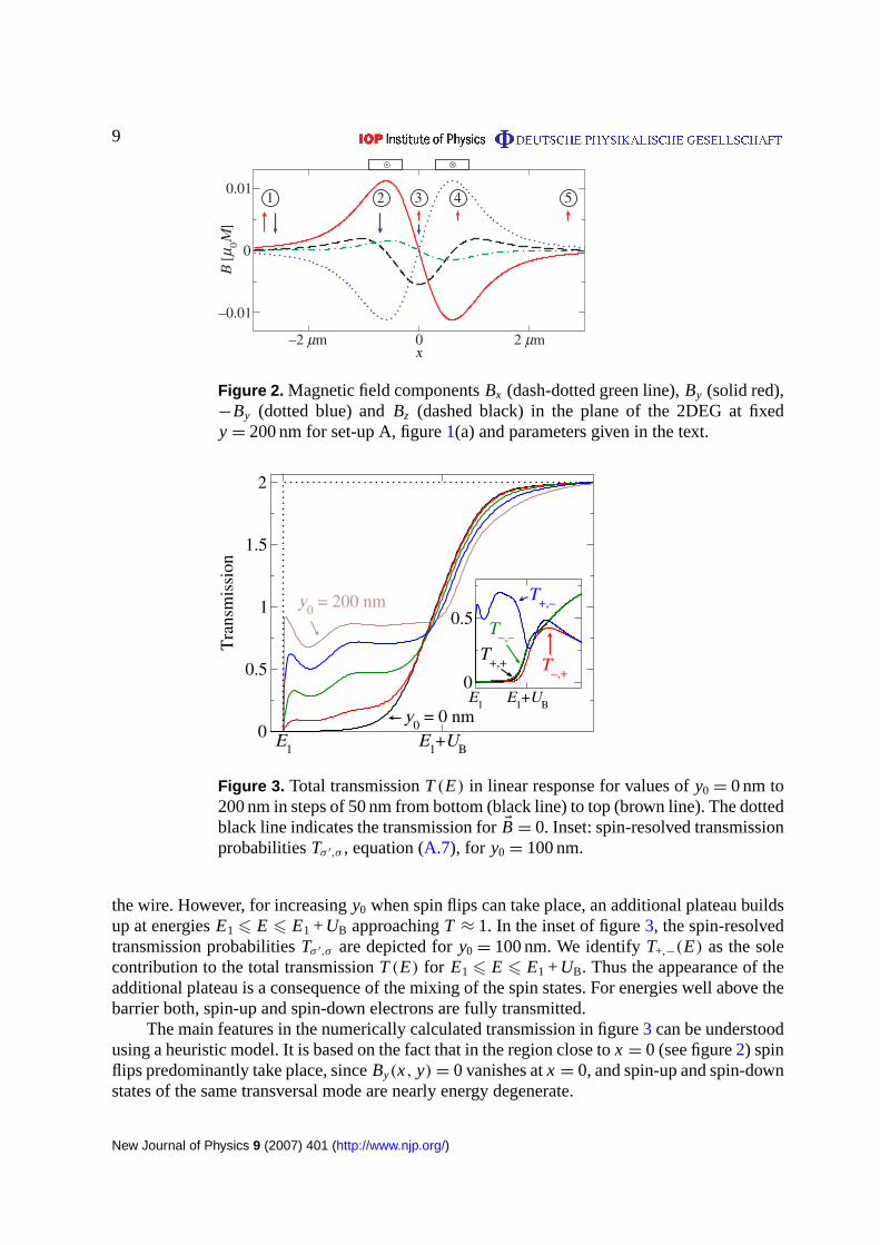
Figure 2. Magnetic field componentsBx (dash-dotted green line),By (solid red),−By (dotted blue) andBz (dashed black) in the plane of the 2DEG at fixedy= 200 nm for set-up A, figure1(a) and parameters given in the text.
E1
E1+U
B0
0.5
1
1.5
2
Tra
nsm
issi
on
E1
E1+U
B
0
0.5T
+,–
T+,+ T
–,+
T–,–
y0 = 200 nm
y0 = 0 nm
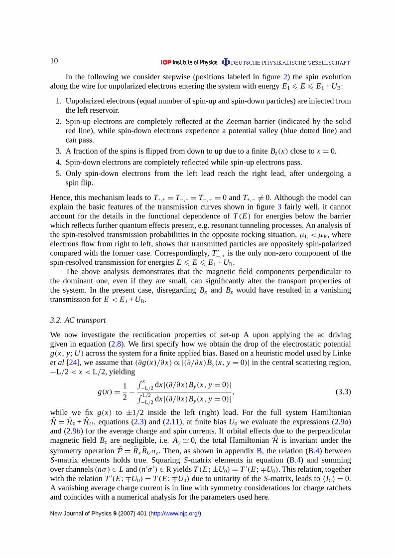
Figure 3. Total transmissionT(E) in linear response for values ofy0= 0 nm to200 nm in steps of 50 nm from bottom (black line) to top (brown line). The dottedblack line indicates the transmission forEB= 0. Inset: spin-resolved transmissionprobabilitiesTσ ′,σ , equation (A.7), for y0= 100 nm.
the wire. However, for increasingy0 when spin flips can take place, an additional plateau buildsup at energiesE16 E 6 E1 +UB approachingT ≈ 1. In the inset of figure3, the spin-resolvedtransmission probabilitiesTσ ′,σ are depicted fory0= 100 nm. We identifyT+,−(E) as the solecontribution to the total transmissionT(E) for E16 E 6 E1 +UB. Thus the appearance of theadditional plateau is a consequence of the mixing of the spin states. For energies well above thebarrier both, spin-up and spin-down electrons are fully transmitted.
The main features in the numerically calculated transmission in figure3 can be understoodusing a heuristic model. It is based on the fact that in the region close tox = 0 (see figure2) spinflips predominantly take place, sinceBy(x, y)= 0 vanishes atx = 0, and spin-up and spin-downstates of the same transversal mode are nearly energy degenerate.
New Journal of Physics 9 (2007) 401 (http://www.njp.org/)
10
In the following we consider stepwise (positions labeled in figure2) the spin evolutionalong the wire for unpolarized electrons entering the system with energyE16 E 6 E1 +UB:
1. Unpolarized electrons (equal number of spin-up and spin-down particles) are injected fromthe left reservoir.
2. Spin-up electrons are completely reflected at the Zeeman barrier (indicated by the solidred line), while spin-down electrons experience a potential valley (blue dotted line) andcan pass.
3. A fraction of the spins is flipped from down to up due to a finiteBz(x) close tox = 0.
4. Spin-down electrons are completely reflected while spin-up electrons pass.
5. Only spin-down electrons from the left lead reach the right lead, after undergoing aspin flip.
Hence, this mechanism leads toT+,+ = T−,+ = T−,− = 0 andT+,− 6= 0. Although the model canexplain the basic features of the transmission curves shown in figure3 fairly well, it cannotaccount for the details in the functional dependence ofT(E) for energies below the barrierwhich reflects further quantum effects present, e.g. resonant tunneling processes. An analysis ofthe spin-resolved transmission probabilities in the opposite rocking situation,µL < µR, whereelectrons flow from right to left, shows that transmitted particles are oppositely spin-polarizedcompared with the former case. Correspondingly,T ′
−,+ is the only non-zero component of thespin-resolved transmission for energiesE 6 E 6 E1 +UB.
The above analysis demonstrates that the magnetic field components perpendicular tothe dominant one, even if they are small, can significantly alter the transport properties ofthe system. In the present case, disregardingBx and Bz would have resulted in a vanishingtransmission forE < E1 +UB.
3.2. AC transport
We now investigate the rectification properties of set-up A upon applying the ac drivinggiven in equation (2.8). We first specify how we obtain the drop of the electrostatic potentialg(x, y;U ) across the system for a finite applied bias. Based on a heuristic model used by Linkeet al [24], we assume that(∂g(x)/∂x)∝ |(∂/∂x)By(x, y= 0)| in the central scattering region,−L/2 < x < L/2, yielding
g(x)=1
2−
∫ x−L/2 dx|(∂/∂x)By(x, y= 0)|∫ L/2−L/2 dx|(∂/∂x)By(x, y= 0)|
, (3.3)
while we fix g(x) to ±1/2 inside the left (right) lead. For the full system HamiltonianH= H0 + HU , equations (2.3) and (2.11), at finite biasU0 we evaluate the expressions (2.9a)and (2.9b) for the average charge and spin currents. If orbital effects due to the perpendicularmagnetic fieldBz are negligible, i.e.Ay ' 0, the total HamiltonianH is invariant under thesymmetry operationP = Rx RUσz. Then, as shown in appendixB, the relation (B.4) betweenS-matrix elements holds true. SquaringS-matrix elements in equation (B.4) and summingover channels(nσ) ∈ L and(n′σ ′) ∈ R yieldsT(E;±U0)= T ′(E;∓U0). This relation, togetherwith the relationT ′(E;∓U0)= T(E;∓U0) due to unitarity of theS-matrix, leads to〈IC〉 = 0.A vanishing average charge current is in line with symmetry considerations for charge ratchetsand coincides with a numerical analysis for the parameters used here.
New Journal of Physics 9 (2007) 401 (http://www.njp.org/)
11
–0.2
–0.1
0
∆TS;
x
0
0.1
0.2
∆TS;
y
E1
E1+U
B
–0.1
0
0.1
∆TS;
z
(a)
(b)
(c)
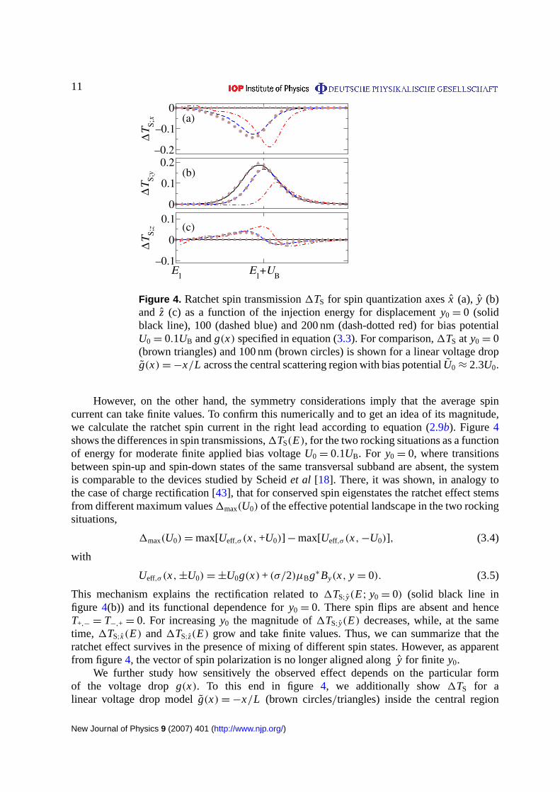
Figure 4. Ratchet spin transmission1TS for spin quantization axesx (a), y (b)and z (c) as a function of the injection energy for displacementy0= 0 (solidblack line), 100 (dashed blue) and 200 nm (dash-dotted red) for bias potentialU0= 0.1UB andg(x) specified in equation (3.3). For comparison,1TS at y0= 0(brown triangles) and 100 nm (brown circles) is shown for a linear voltage dropg(x)=−x/L across the central scattering region with bias potentialU0≈ 2.3U0.
However, on the other hand, the symmetry considerations imply that the average spincurrent can take finite values. To confirm this numerically and to get an idea of its magnitude,we calculate the ratchet spin current in the right lead according to equation (2.9b). Figure4shows the differences in spin transmissions,1TS(E), for the two rocking situations as a functionof energy for moderate finite applied bias voltageU0= 0.1UB. For y0= 0, where transitionsbetween spin-up and spin-down states of the same transversal subband are absent, the systemis comparable to the devices studied by Scheidet al [18]. There, it was shown, in analogy tothe case of charge rectification [43], that for conserved spin eigenstates the ratchet effect stemsfrom different maximum values1max(U0) of the effective potential landscape in the two rockingsituations,
1max(U0)=max[Ueff,σ (x, +U0)]−max[Ueff,σ (x,−U0)], (3.4)
with
Ueff,σ (x,±U0)=±U0g(x) + (σ/2)µBg∗By(x, y= 0). (3.5)
This mechanism explains the rectification related to1TS;y(E; y0= 0) (solid black line infigure 4(b)) and its functional dependence fory0= 0. There spin flips are absent and henceT+,− = T−,+ = 0. For increasingy0 the magnitude of1TS;y(E) decreases, while, at the sametime, 1TS;x(E) and1TS;z(E) grow and take finite values. Thus, we can summarize that theratchet effect survives in the presence of mixing of different spin states. However, as apparentfrom figure4, the vector of spin polarization is no longer aligned alongy for finite y0.
We further study how sensitively the observed effect depends on the particular formof the voltage dropg(x). To this end in figure4, we additionally show1TS for alinear voltage drop modelg(x)=−x/L (brown circles/triangles) inside the central region
New Journal of Physics 9 (2007) 401 (http://www.njp.org/)
12
0 0.05 0.1 0.15 0.2U
0 / U
B
–0.2
0
0.2
0.4
⟨Is⟩ (
e /U
0) [e
/8π]
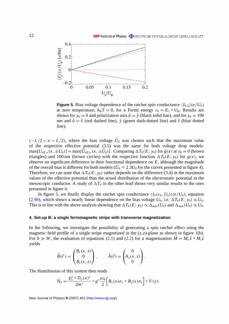
Figure 5. Bias voltage dependence of the ratchet spin conductance〈IS;u〉(e/U0)
at zero temperature,kBT = 0, for a Fermi energyεF= E1 +UB. Results areshown fory0= 0 and polarization axisu= y (black solid line), and fory0= 100nm andu= x (red dashed line),y (green dash-dotted line) andz (blue dottedline).
(−L/2 < x < L/2), where the bias voltageU0 was chosen such that the maximum valueof the respective effective potential (3.5) was the same for both voltage drop models:max[Ueff,σ (x,±U0)] =max[Ueff,σ (x,±U0)] . Comparing1TS(E; y0) for g(x) at y0= 0 (browntriangles) and 100 nm (brown circles) with the respective function1TS(E; y0) for g(x), weobserve no significant difference in their functional dependence onE, although the magnitudeof the overall bias is different for both models (U0≈ 2.3U0 for the curves presented in figure4).Therefore, we can state that1TS(E; y0) rather depends on the difference (3.4) in the maximumvalues of the effective potential than the actual distribution of the electrostatic potential in themesoscopic conductor. A study of1TS in the other lead shows very similar results to the onespresented in figure4.
In figure 5, we finally display the ratchet spin conductance〈IS(εF,U0)〉(e/U0), equation(2.9b), which shows a nearly linear dependence on the bias voltageU0, i.e. 1TS(E; y0)∝U0.This is in line with the above analysis showing that1TS(E; y0)∝1max(U0) and1max(U0)∝U0.
4. Set-up B: a single ferromagnetic stripe with transverse magnetization
In the following, we investigate the possibility of generating a spin ratchet effect using themagnetic field profile of a single stripe magnetized in the (x,z)-plane as shown in figure1(b).For b�W, the evaluation of equations (2.1) and (2.2) for a magnetizationEM = Mx x + Mzzyields
EB(Er )=
Bx(x, z)0
Bz(x, z)
, EA(Er )=
0Ay(x, z)
0
.
The Hamiltonian of this system then reads
H0=p2
x +5y(x)2
2m∗+ g∗
µB
2
[Bx(x)σx + Bz(x)σz
]+ V(y).
New Journal of Physics 9 (2007) 401 (http://www.njp.org/)
13
1 µm0–1 µmx
–0.2
0
0.2
B [
µ 0M]
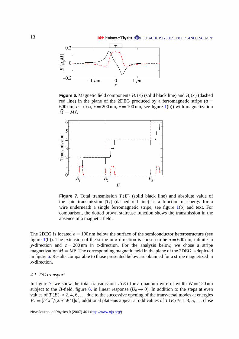
Figure 6. Magnetic field componentsBx(x) (solid black line) andBz(x) (dashedred line) in the plane of the 2DEG produced by a ferromagnetic stripe (a=600 nm,b→∞, c= 200 nm,e= 100 nm, see figure1(b)) with magnetizationEM = Mz.
E1
E2
E3
E
0
1
2
3
4
5
6
Tra
nsm
issi
on
Figure 7. Total transmissionT(E) (solid black line) and absolute value ofthe spin transmission|TS| (dashed red line) as a function of energy for awire underneath a single ferromagnetic stripe, see figure1(b) and text. Forcomparison, the dotted brown staircase function shows the transmission in theabsence of a magnetic field.
The 2DEG is locatede= 100 nm below the surface of the semiconductor heterostructure (seefigure 1(b)). The extension of the stripe inx-direction is chosen to bea= 600 nm, infinite iny-direction and c= 200 nm in z-direction. For the analysis below, we chose a stripemagnetizationEM = Mz. The corresponding magnetic field in the plane of the 2DEG is depictedin figure6. Results comparable to those presented below are obtained for a stripe magnetized inx-direction.
4.1. DC transport
In figure 7, we show the total transmissionT(E) for a quantum wire of width W= 120 nmsubject to theB-field, figure6, in linear response (U0→ 0). In addition to the steps at evenvalues ofT(E)≈ 2, 4, 6, . . . due to the successive opening of the transversal modes at energiesEn = [h2π2/(2m∗W2)]n2, additional plateaus appear at odd values ofT(E)≈ 1, 3, 5, . . . close
New Journal of Physics 9 (2007) 401 (http://www.njp.org/)
14
to the energiesEn. As in section3, we can attribute these features to the lifted spin degeneracydue to the Zeeman field, since also the width of these plateaus corresponds to twice the absoluteheight of the Zeeman barrierUB = (g∗/2) µB max[| EB|] inside the wire.
In figure 7, we furthermore plot the absolute value of the spin transmission,| TS| =√(TS;x)2 + (TS;y)2 + (TS;z)2, which approaches unity at energies of the additional plateaus.
A closer look at the spin- and mode-resolved transmission probabilities reveals that thetransmission of the highest occupied transversal subband is completely spin polarized at theplateaus, while the lower modes are fully transmitting spin-up and spin-down particles. Similarresults were reported by Zhai and Xu [31] for a stripe magnetized in thex-direction.
Apart from the spin effects due to the Zeeman term, the vector potential componentAy,affecting the orbital dynamics of the electrons due to the perpendicular magnetic fieldBz,influences the electron transport. In a classical picture,Bz forces electrons to move on segmentsof cyclotron orbits in the plane of the 2DEG. Therefore, the kinetic energy in the direction ofmotion is reduced resulting in a shift of the energies where the transversal modes open towardshigher values [44]. This is visible in figure7, when comparing the total transmission with (solidblack line) and without (dotted brown line) magnetic field.
4.2. AC transport
As for set-up A, we employ a heuristic model for the voltage drop inside the mesoscopicconductor, assuming∂g(x)/∂x ∝ |(∂/∂x)| EB(x)|| inside the central region(−L/2 < x < L/2)
yielding
g(x)=1
2−
∫ x−L/2 dx |(∂/∂x)| EB(x)||∫ L/2−L/2 dx |(∂/∂x)| EB(x)||
.
However, before we numerically investigate the ac ratchet transport properties, we exploitcertain symmetries present in the system to simplify the expressions for the average net charge(2.9a) and spin currents (2.9b). For the magnetic field profile produced by a stripe magnetizedin z-direction it is straightforward to show from equations (2.1) and (2.2) that the followingsymmetry relations hold true (see also figure6):
Bx(−x)=−Bx(x), Bz(−x)= Bz(x),
Ay(−x)=−Ay(x), g(−x)=−g(x) .
Thus the HamiltonianH= H0 + HU is invariant under the action of the operatorP =−iC Rx RUσz, whereC is the operator of complex conjugation,Rx inverses thex-coordinate,RU changes the sign of the applied voltage(±U0→∓U0) andσz is the Pauli spin operator.Due to [H, P] = 0, we are able to interrelate the transmission probabilities for both rockingsituations as shown in appendixB. Taking the square of equation (B.3) and summing over thetransversal modesn ∈ L andn′ ∈ R, we obtain the following relations between the spin-resolvedtransmission probabilities in the two rocking situations:
T (θ,φ)
σ,σ ′ (E,±U0)= T (θ,−φ+π)
σ ′,σ (E,∓U0).
New Journal of Physics 9 (2007) 401 (http://www.njp.org/)
15
–0.050
0.050.1
–0.02
0
0.02
En En+3UB
–0.02
0
0.02
n = 1
n = 2
n = 3(c)
(b)
(a)
∆TS
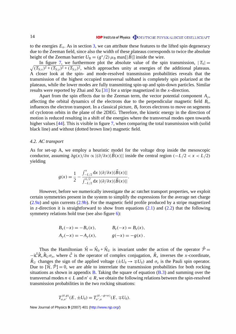
Figure 8. Averaged net spin transmission1TS(E;U0) for spin polarization axesx (solid black line),y (dash-dotted red line) andz (dashed blue line) as a functionof energy close to the lowest three transversal energy levelsEn(n= 1, 2 and 3)for an applied bias voltage ofU0= 0.1UB.
Here, the superscript labels the angles of the spin quantization axis on the Bloch sphere (seeappendixB). Thus the ratchet charge current (2.9a) vanishes,
〈IC(εF,U0)〉 = 0,
and we can express the ratchet spin current (2.9b) through the transmission probabilities of asingle rocking situation (e.g. +U0):
〈IS;x(εF,U0)〉 =1
4π
∫∞
0dE1 f (E; εF,U0)
[T+,+(E, +U0)− T−,−(E, +U0)
],
〈IS;y/z(εF,U0)〉 =1
4π
∫∞
0dE 1 f (E; εF,U0)
[T+,−(E, +U0)− T−,+(E, +U0)
].
Figure8 shows the ratchet spin transmission1TS(E;U0) at a finite applied voltageU0= 0.1UB
for a wire of widthW = 120 nm. This quantity is finite for energies where the dc transmission isspin polarized (see figure7). Furthermore, the spin polarization of the ratchet spin transmissiondepends on the injection energy. This opens the possibility to tune it upon varying theFermi energy. Comparing the ratchet spin transmission forn= 1 (figure 8 (a)) andn= 2, 3(figures8(b) and (c)), we observe that its magnitude is significantly lower in the case wheremore than one transversal mode is conducting. This behavior is due to the mixing of differenttransversal subbands due toAy(x). To quantify this effect, we introduce
1TS,max(n)= maxE∈[En,En+1]
[√1TS;x(E)2 +1TS;y(E)2 +1TS;z(E)2
],
New Journal of Physics 9 (2007) 401 (http://www.njp.org/)
16
1 1.5 2 2.5 3µ
0M [T]
0
0.5
1
100 150W [nm]
0
0.5
1
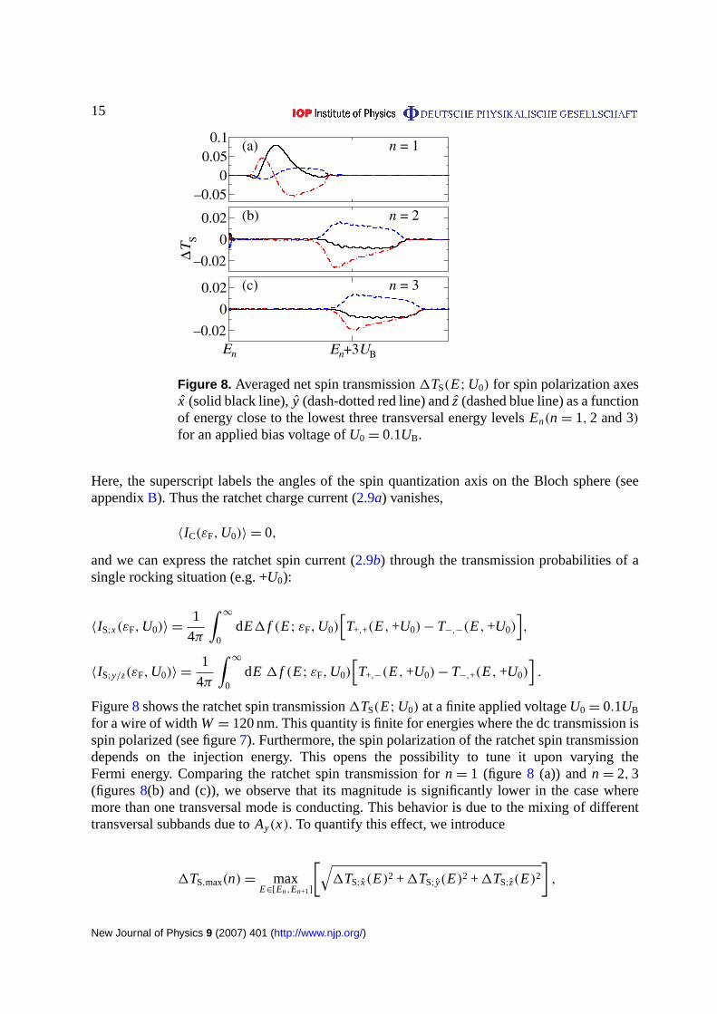
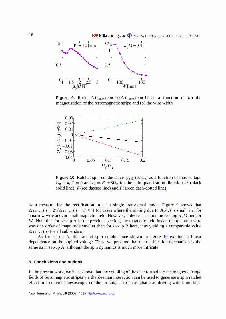
(a) (b)W = 120 nm µ0M = 3 T
Figure 9. Ratio 1TS,max(n= 2)/1TS,max(n= 1) as a function of (a) themagnetization of the ferromagnetic stripe and (b) the wire width.
0 0.05 0.1 0.15 0.2U
0 / U
B
–0.04–0.03–0.02–0.01
00.010.020.03
⟨Is⟩ (
e /U
0) [e
/8π]
Figure 10. Ratchet spin conductance〈IS,u〉(e/U0) as a function of bias voltageU0 at kBT = 0 andεF= E3 + 3UB for the spin quantization directionsx (blacksolid line), y (red dashed line) andz (green dash-dotted line).
as a measure for the rectification in each single transversal mode. Figure9 shows that1TS,max(n= 2)/1TS,max(n= 1)≈ 1 for cases where the mixing due toAy(x) is small, i.e. fora narrow wire and/or small magnetic field. However, it decreases upon increasingµ0M and/orW. Note that for set-up A in the previous section, the magnetic field inside the quantum wirewas one order of magnitude smaller than for set-up B here, thus yielding a comparable value1TS,max(n) for all subbandsn.
As for set-up A, the ratchet spin conductance shown in figure10 exhibits a lineardependence on the applied voltage. Thus, we presume that the rectification mechanism is thesame as in set-up A, although the spin dynamics is much more intricate.
5. Conclusions and outlook
In the present work, we have shown that the coupling of the electron spin to the magnetic fringefields of ferromagnetic stripes via the Zeeman interaction can be used to generate a spin ratcheteffect in a coherent mesoscopic conductor subject to an adiabatic ac driving with finite bias.
New Journal of Physics 9 (2007) 401 (http://www.njp.org/)
17
The proposed devices exhibit the appealing property of creating a directed net spin current inthe absence of an accompanying net charge transport. This key result has been demonstrated innumerical approaches for set-ups A and B, in the case of set-up B, also analytically based onsymmetry properties of the system.
The generated spin current may be regarded as resulting from a rectification effect, howeverin a generalized sense: the direct analog of a charge current rectifier would be a systemgenerating a directed spin current out of a conductor with alternatingspin-chemicalpotentialsin the left and right reservoir. Spin ratchets, such as the ones considered here, act differently asthey convert an acelectricalbias into a net spin current.
From our analysis, we have identified the difference in the maximum values of the effectiveZeeman potentials in the respective rocking situations as responsible for the creation of thespin current. It has been shown that this rectification effect is almost independent of theactual distribution of the electrostatic potential in the biased conductor. Furthermore, the factthat, for the systems considered here, the difference in the maximum values of the Zeemanpotential is crucial for the spin currents, implies that the magnitude of the spin current cannotbe systematically increased upon increasing the number of magnetic stripes, e.g. in a periodicarrangement of stripes. We have checked this also numerically by adding an increasing numberof stripes.
In the preceding sections, we presented results when evaluating the spin current inside theright lead. However, as we noted both systems considered, set-ups A and B, are characterizedby interesting symmetry properties. Those can now be used to directly extract the respectivecurrents inside the left lead. If for set-up A the componentAx can be neglected, as it isappropriate for the parameters used in section3, the combined Hamiltonian of the system andthe leads has been proven to be invariant under the action of the symmetry operationRx Ry RUσz,while for set-up B the Hamiltonian is invariant under the action ofRx RUσz. These symmetryproperties are reflected in equations (B.4) and (B.5) respectively, see appendixB. Both relationslead to the general relation
T ′(θ,φ+π)
σ,σ ′ (E,∓U0)= T (θ,φ)
σ,σ ′ (E,±U0),
between the transmission probabilities in the two rocking situations. This relation allows for thefollowing interpretation. If the transmitted electrons are spin-polarized in one of the two rockingsituations with direction of the polarization vector given by the angles(θ, φ) on the Blochsphere, then in the other rocking situation the spin polarization vector of the output current (inthe other lead) will be rotated around thez-axis byπ and thus points to(θ, φ +π). This propertyis a direct consequence of the lacking conservation of the spin eigenstates inside the wire.
The physics of semiconducting materials characterized by a largeg∗ factor is dominatedby the presence of magnetic impurities, e.g. diluted magnetic semiconductors [34]. Therefore,in order to exploit the expected stronger rectification effect, we have to take elastic scattering offimpurities into account. In particular, we plan to study how additional disorder alters the spinratchet effects.
Finally, since the heuristic model used for the distribution of the electrostatic potentialin the conductor is convenient but not fully satisfactory, it would be desirable to calculate thecharge density and the respective electrostatic potential inside the wire self-consistently. Workin this direction is in progress.
New Journal of Physics 9 (2007) 401 (http://www.njp.org/)
18
Acknowledgments
We acknowledge discussions with and computational support by Michael Wimmer. Thisresearch has been supported by the Deutsche Forschungsgemeinschaft within the cooperativeresearch center SFB 689 ‘Spin phenomena in reduced dimensions’ and the research traininggroup GRK 638. MS acknowledges support through the Studienstiftung des Deutschen Volkes.
Appendix A. Calculation of the spin current in the Landauer–Büttiker formalism
In this appendix, we present a derivation of the expressions for spin current in the leads of amultiterminal coherent conductor within the framework of the Landauer–Büttiker theory [45].To this end, we considerN non-ferromagnetic contacts, injecting spin-unpolarized current intothe leads. For convenience, we use a local coordinate system for the lead under investigation,wherex is the coordinate along the lead in the direction of charge propagation due to an appliedbias in linear response andy is the transverse coordinate. Then the eigenfunctions inside a leadare given by
8±E,nσ (x, y)=1
√kx(E)
e±ikx(E)xχn(y)6(σ), (A.1)
where theχn(y) are the transverse eigenfunctions of the lead with the transversal eigenenergyEn and 6(σ) is the spin eigenfunction. The superscript± of 8 refers to the direction ofmotion in±x-direction with the wavevectorkx =
√2m∗(E− En)/h. For the derivation we use
the scattering approach, where the amplitudes of the states inside the leads are related via thescattering matrixS(E), determined by the Hamiltonian of the coherent conductor. Inside leadqa given scattering state
ϕqE(x, y)=
∑(nσ)∈q
(aq
nσ (E)8+E,nσ (x, y) + bq
nσ (E)8−E,nσ (x, y)),
(σ =±), consists of incoming states8+ entering the coherent conductor from contactq andoutgoing states8− leaving the coherent conductor into contactq. The amplitudes of incominga j
nσ and outgoing wavesbin′σ ′ are related via the equation
bin′σ ′(E)=
N∑j=1
∑n∈ j
∑σ=±1
Si, jn′σ ′,nσ (E)a j
nσ (E), (A.2)
where the scattering matrixS(E) has the following structure for anN terminal system:
S(E)=
r1,1(E) t1,2(E) · · · t1,N(E)
t2,1(E) r2,2(E) · · · t2,N(E)...
.... . .
...
tN,1(E) tN,2(E) · · · r N,N(E)
.
Here the sub-matrixr j, j (E) is a square matrix of dimensionalityM j (E), corresponding to thenumber of open channels at energyE in lead j (already including the spin degree of freedom),which is connected to a reservoir with chemical potentialµ j . The matrix r j, j (E) containsthe scattering amplitudes of incoming channels of leadj being reflected back into outgoingchannels of the same lead. The sub-matrixt i, j (E) is aM i (E)×M j (E) matrix that contains the
New Journal of Physics 9 (2007) 401 (http://www.njp.org/)
19
scattering amplitudes for transmission between incoming channels from leadj and outgoingchannels of leadi .
The wavefunction of the scattering state inside leadi , where only the incoming channel(nσ) ∈ j is populated(a j ′
n′σ ′ = δ j ′, j δn′,nδσ ′,σ ), reads forj = i :
ϕ iE,nσ (x, y)=8+
E,nσ (x, y) +∑
(n′σ ′)∈i
r i,in′σ ′,nσ (E)8−E,n′σ ′(x, y), (A.3)
and, correspondingly, forj 6= i
ϕ iE,nσ (x, y)=
∑(n′σ ′)∈i
t i, jn′σ ′,nσ (E)8−E,n′σ ′(x, y). (A.4)
For a wavefunction9(x, y) the spin currentI 9S (x) passing a cross section (x = const.) of a lead
is given by:
I 9S (x)=
∫dy 9∗(x, y) JS9(x, y). (A.5)
Here, we use the most common definition of the spin current operator [36], which with respectto an arbitrary quantization axisu takes the following form inside the leads:
JS=h
2
h
2m∗i
(Eσ · u
) (−→∂∂x−
←−∂
∂x
).
The partial derivatives act on the expressions to their right/left respectively (indicated by thearrows). For the scattering state (A.3) we then obtain for the spin current (A.5) inside leadi
I j=iS;E,nσ (x ∈ i )=
h2
2m∗
[σ −
∑(n′σ ′)∈i
σ ′∣∣r i,i
n′σ ′,nσ (E)∣∣2] ,
where (nσ ∈ j, j = i ). For the scattering state (A.4) we find the corresponding expression(nσ ∈ j, j 6= i )
I j 6=iS;E,nσ (x ∈ i )=−
h2
2m∗∑
(n′σ ′)∈i
σ ′∣∣∣t i, j
n′σ ′,nσ (E)
∣∣∣2 .
Since every channel is populated according to the Fermi–Dirac distributionf (E;µq) of therespective contactq, the total spin current in leadi then reads
IS(x ∈ i )=m∗
2π h2
∫∞
0dE
[ N∑j=1
∑(nσ)∈ j
f (E;µ j )I jS;E,nσ (x ∈ i )
]=−1
4π
∫∞
0dE
[f (E;µi )Ri,i
S (E) +∑q 6=i
f (E;µq)Ti,q
S (E)], (A.6)
where
T i,qS (E)=
∑σ ′=±
(T i,q
+,σ ′ − T i,q−,σ ′
), Ri,i
S (E)=∑σ ′=±
(Ri,i
+,σ ′ − Ri,i−,σ ′
),
New Journal of Physics 9 (2007) 401 (http://www.njp.org/)
20
and
T i,qσ,σ ′(E)=
∑n∈i
∑n′∈q
∣∣∣t i,qnσ,n′σ ′(E)
∣∣∣2 , (A.7)
Ri,iσ,σ ′(E)=
∑n∈i
∑n′∈i
∣∣r i,inσ,n′σ ′(E)
∣∣2 . (A.8)
SinceS(E) is unitary, the following relation holds true:
∑(n′σ ′)∈i
∣∣r i,inσ,n′σ ′(E)
∣∣2 +∑q 6=i
∑(n′′σ ′′)∈q
∣∣∣t i,qnσ,n′′σ ′′(E)
∣∣∣2= 1.
Then it is straightforward to show that
Ri,iS (E) +
∑q 6=i
T i,qS (E)= 0,
In view of equation (A.6), we eventually find for the spin current in leadi
IS(x ∈i )=1
4π
∫∞
0dE
∑q 6=i
[f (E;µi )− f (E;µq)
]T i,q
S (E). (A.9)
Although equilibrium spin currents can locally exist in systems with SO interactions as shownfor 2DEGs [46] and in mesoscopic systems [47], equation (A.9) clearly shows that in thermalequilibrium (µ j = µ) the spin current inside leads without SO interactions and magnetic fieldsvanishes. This absence of equilibrium spin currents in the leads has been shown for systemswith preserved time-reversal symmetry [48]. However, here we show that it is more generallyvalid for any coherent conductor, since we did not make any assumptions about symmetries ofthe scattering region in the course of the derivation.
We note that the relation (5) derived by Pareek [49] that allows for equilibrium spincurrents, has to be regarded as incorrect, arising from an improper treatment of the back-reflection, missing the term
1
4π
∫∞
0dE f (E;µi )2
(Ri,i−,+(E)− Ri,i
+,−(E)), (A.10)
in comparison with equation (A.9). This issue has been addressed by Nikolicet al [50].However, their argumentation that the term (A.10) has only to be included in equilibrium, i.e.for energies up to the lowest chemical potential of theN terminals, seems questionable. Ifthe spin current is evaluated in a lead connected to a reservoirk with µk > µl (µl being thelowest chemical potential of any of theN reservoirs), the full expression (A.9) has to be used.Furthermore, a simplified version of equation (A.9),
IS=1
4π
∑q 6=i
(µi −µq)Ti,q
S ,
where transport at zero temperature and energy-independent transmission probabilities wereconsidered, has been used in recent publications on the mesoscopic spin Hall effect [51].
New Journal of Physics 9 (2007) 401 (http://www.njp.org/)
21
Appendix B. Derivation of symmetry relations for spin-dependent Landauertransport at finite bias
Here, we derive symmetry relations for a two terminal set-up as used in this paper. We generalizerelated expressions from [52] to finite bias and arbitrary spin quantization axis.
If the Hamiltonian of the total system of scattering region and leads is invariant undercertain symmetry operationsP, we can relate the elements of the scattering matrix even indifferent rocking situations. As an example, we derive the symmetry relations stemming fromthe symmetry operatorP =−iC Rx RUσz, whereC is the operator of complex conjugation,Rx
inverts thex-coordinate,RU changes the sign of the applied voltage(±U0→∓U0) andσz isthe Pauli spin operator.
Generalizing equation (A.1) of appendixA the eigenfunctions inside the leads are given by
8±,(θ,φ)
E,nσ (x, y)=1
√kx(E)
e±ikx(E)xχn(y)6(θ,φ)(σ ), (B.1)
with the spin eigenstates
6(θ,φ)(+)=
(cosθ
2e−iφ/2
sinθ
2eiφ/2
), 6(θ,φ)(−)=
(− sin θ
2e−iφ/2
cosθ
2eiφ/2
),
defined with respect to the quantization axis
u=
sinθ cosφsinθ sinφ
cosθ
.
The effect ofP on the eigenstates (B.1) is to change an incoming state in the left lead (L) inone rocking situation into an outgoing state of the right lead (R) in the other rocking situationand vice versa. Furthermore, the position of the spin on the Bloch sphere is changed from(θ, φ)
into (θ,−φ +π), and the amplitude of the state is complex conjugated.On the other hand, the action ofP cannot change the scattering-matrix, since the
Hamiltonian is invariant under the action ofP. Therefore, the following relation holds true:
a(θ,−φ+π)∗
nσ (E,∓U0)=∑
n′∈(L∪R)
∑σ ′=±1
S(θ,φ)
nσ,n′σ ′(E,±U0)b(θ,−φ+π)∗
n′σ ′ (E,∓U0). (B.2)
Here, the mode indexn is related to moden of the opposite lead by means of the symmetrytransformation. Comparing equation (B.2) with the inverse of equation (A.2),
a(θ,−φ+π)nσ (E,∓U0)=
∑n′∈(L∪R)
∑σ ′=±1
[S(θ,−φ+π)
]−1
nσ,n′σ ′(E,∓U0)b
(θ,−φ+π)
n′σ ′ (E,∓U0) ,
and using the unitarity of the scattering matrix,S−1= S†= (S∗)t, we find the symmetry relation
for the scattering amplitudes
S(θ,−φ+π)
nσ,n′σ ′ (E,∓U0)= S(θ,φ)
n′σ ′,nσ (E,±U0). (B.3)
New Journal of Physics 9 (2007) 401 (http://www.njp.org/)
22
Similar relations can be obtained for any other symmetry operator that commutes with theHamiltonianH. For the other two operators used in this paper,Rx RUσz and Rx Ry RUσz, theabove procedure can be applied accordingly. It yields
S(θ,φ+π)
nσ,n′σ ′ (E,∓U0)= S(θ,φ)
nσ,n′σ ′(E,±U0) (B.4)
for [H, Rx RUσz] = 0 and
S(θ,φ+π)
nσ,n′σ ′ (E,∓U0)= pn pn′S(θ,φ)
nσ,n′σ ′(E,±U0) (B.5)
for [H, Rx Ry RUσz] = 0, where pn = (−1)n−1 is the parity of the eigenfunctionχn(y) inequation (B.1).
References
[1] Datta S and Das B 1990Appl. Phys. Lett.56665[2] Rashba E I 1960Sov. Phys. Solid State2 1109[3] Schmidt G, Ferrand D, Molenkamp L W, Filip A T and van Wess B J 2000Phys. Rev.B 62R4790[4] Fiederling R, Keim M, Reuscher G, Ossau W, Schmidt G, Waag A and Molenkamp L W 1999Nature
402787[5] Ohno Y, Young D K, Beschoten B, Matsukura F, Ohno H and Awschalom D D 1999Nature402790[6] Ganichev S D, Danilov S N, Eroms J, Wegscheider W, Weiss D, Prettl W and Ivchenko E L 2001Phys. Rev.
Lett.864358[7] Murakami S, Nagaosa N and Zhang S C 2003Science3011348[8] Sinova J, Culcer D, Niu Q, Sinitsyn N A, Jungwirth T and MacDonald A H 2004Phys. Rev. Lett.92126603[9] Kato Y K, Mayer R C, Gossard A C and Awschalom D D 2004Science3061910
[10] Wunderlich J, Kaestner B, Sinova J and Jungwirth T 2005Phys. Rev. Lett.9447204[11] Sih V, Myers R C, Kato Y K, Lau W H, Gossard A C and Awschalom D D 2005Nat. Phys.1 31[12] Valenzuela S O and Tinkham M 2006Nature442176[13] Kimura T, Otani Y, Sato T, Takahashi S and Maekawa S 2007Phys. Rev. Lett.98156601
Kimura T, Otani Y, Sato T, Takahashi S and Maekawa S 2007Phys. Rev. Lett.98249901 (erratum)[14] Sharma P and Chamon C 2001Phys. Rev. Lett.8796401[15] Mucciolo E R, Chamon C and Marcus C M 2002Phys. Rev. Lett.89146802[16] Governale M, Taddei F and Fazio R 2003Phys. Rev.B 68155324[17] Scheid M, Pfund A, Bercioux D and Richter K 2007Phys. Rev.B 76195303(Preprintcond-mat/0601118)[18] Scheid M, Wimmer M, Bercioux D and Richter K 2006Phys. Status Solidic 3 4235[19] Brouwer P W 1998Phys. Rev.B 58R10135[20] Watson S K, Potok R M, Marcus C M and Umansky V 2003Phys. Rev. Lett.91258301[21] Reimann P 2002Phys. Rep.36157[22] Reimann P, Grifoni M and Hänggi P 1997Phys. Rev. Lett.7910[23] Linke H, Humphrey T E, Löfgren A, Sushkov A O, Newbury R, Taylor R P and Omling P 1999Science
2682314[24] Linke H, Humphrey T R, Lindelof P R, Löfgren A, Newbury R, Omling P, Sushkov A O, Taylor R P and
Xu H 2002Appl. Phys.A 75237[25] Braunecker B, Feldman D E and Li F 2007Phys. Rev.B 76085119[26] Matulis A, Peeters F M and Vasilopoulos P 1994Phys. Rev. Lett.721518[27] Ye P D, Weiss D, Gerhardts R R, Seeger M, Klitzing K von, Eberl K and Nickel H 1995Phys. Rev. Lett.
743013[28] Kubrak V, Rahman F, Gallagher B L, Main P C, Henini M, Marrows C H and Howson M A 1999Appl. Phys.
Lett.742507
New Journal of Physics 9 (2007) 401 (http://www.njp.org/)
23
[29] Kubrak V, Neumann A C, Gallagher B L, Main P C, Henini M, Marrows C H and Howson M A 2000PhysicaE 6 755
[30] Jackson J D 1999Classical Electrodynamics(New York: Wiley)[31] Zhai F and Xu H Q 2006Appl. Phys. Lett.88032502[32] Lu M, Zhang L, Jin Y and Yan X 2002Eur. Phys. J.B 27565[33] Slobodskyy A, Gould C, Slobodskyy T, Becker C R, Schmidt G and Molenkamp L W 2003Phys. Rev. Lett.
90246601[34] Furdyna J K 1988J. Appl. Phys.64R29[35] Madelung O 2003Semiconductors: Data Handbook(Berlin: Springer)[36] Rashba E I 2005J. Supercond.18137[37] Waintal X, Myers E B, Brouwer P W and Ralph D C 2000Phys. Rev.B 6212317[38] Shi J, Zhang P, Xiao D and Niu Q 2006Phys. Rev. Lett.9676604[39] Büttiker M 1993J. Phys.: Condens. Matter5 9361[40] Christen T and Büttiker M 1996Europhys. Lett.35523[41] Xu H 1993Phys. Rev.B 4715630[42] Lassl A, Schlagheck P and Richter K 2007Phys. Rev.B 75045346[43] Sablikov V A, Borisov V I and Chmil’ A I 2005JETP Lett.8175[44] Governale M and Boese D 2000Appl. Phys. Lett.773215[45] Büttiker M, Imry Y, Landauer R and Pinhas S 1985Phys. Rev.B 316207[46] Rashba E I 2003Phys. Rev.B 68241315[47] Nikolic B K, Zârbo L P and Souma S 2006Phys. Rev.B 73075303[48] Kiselev A A and Kim K W 2005Phys. Rev.B 71153315[49] Pareek T P 2004Phys. Rev. Lett.92076601[50] Nikolic B K, Zârbo L P and Souma S 2005Phys. Rev.B 72075361[51] Hankiewicz E M, Molenkamp L W, Jungwirth T and Sinova J 2004Phys. Rev.B 70241301
Ren W, Qiao Z, Wang Q Sun and Guo H 2006Phys. Rev. Lett.97066603Bardarson J H, Adagideli I and Jacquod P 2007Phys. Rev. Lett.98196601
[52] Zhai F and Xu H Q 2005Phys. Rev. Lett.94246601
New Journal of Physics 9 (2007) 401 (http://www.njp.org/)