ZEDi 10 / ZEDi 10FX - Professional audio mixing consoles · ZEDi-10 / ZEDi-10FX 10 Channel Live +...
12
ZEDi - 10 / ZEDi - 10FX 10 Channel Live + Recording Mixer User Guide Thank you for purchasing this Allen & Heath ZEDi-10 or ZEDi-10FX! We recommend that you read all of this user guide to get the best from your mixer and after reading, please keep this safe for future reference. Included in this package is: ZEDi-10 / ZEDi-10FX Mixer. IEC C5 Mains Power Cable. Please check correct mains plug is fitted for your country. USB A-B Cable 2M. This User Guide!
Transcript of ZEDi 10 / ZEDi 10FX - Professional audio mixing consoles · ZEDi-10 / ZEDi-10FX 10 Channel Live +...

ZEDi-10 / ZEDi-10FX 10 Channel Live + Recording Mixer User Guide
Thank you for purchasing this Allen & Heath ZEDi-10 or ZEDi-10FX!
We recommend that you read all of this user guide to get the best from your mixer and after
reading, please keep this safe for future reference.
Included in this package is:
ZEDi-10 / ZEDi-10FX Mixer.
IEC C5 Mains Power Cable. Please check correct mains plug is fitted for your country.
USB A-B Cable 2M.
This User Guide!

2
1. Get to know your mixer
1.1 MONO INPUT CHANNELS (M)
1. Mic Input Socket uses a standard 3-Pin XLR socket for connecting
dynamic or condenser microphones.
2. Line / Inst Input Socket uses a standard 1/4” (6.25mm) Jack socket
for connecting balanced or unbalanced signals such as guitars and other instruments.
3. Gain Control adjusts the gain of the input preamplifier to drive the
source signal level. Gain ranges from 5dB to 60dB.
4. Instrument activates the Line / Inst input circuit for electro-acoustic and electric guitars, basses and other Direct Input
instruments. When activated the Mic Input Socket is disabled.
5. For channels M3 and M4 this is replaced by a LINE/PAD switch. This activates the LINE input and a PAD circuit which reduces the Mic Input
Socket gain level by -20dB for very loud sources.
6. lo-cut (Hi-Pass Filter) is used for reducing Low Frequency noise such as handling noise, popping, rumble and proximity effect in microphone signals.
7. HF EQ (High Frequency) equaliser affects treble frequencies in the signal for adding “brightness” and “definition” or for reducing “hiss” and “harshness”.
8. MF EQ (Mid Frequency) equaliser affects frequencies in the signal
for adding “presence” or for removing “boxiness”.
9. LF EQ (Low Frequency) equaliser affects bass frequencies in the
signal to cover “boom” and “sub-bass” frequencies.
10. AUX send controls the amount of signal sent from the channel to the aux buss and AUX OUT. The signal is sourced pre-fader (MIX) so is independent of the level being sent to the main L-R Mix. There is a master level control for the AUX OUT.
11. FX send controls the amount of signal sent from the channel to the FX buss and the FX OUT. The signal is post-fader (MIX) which means it’s affected by the channel MIX control so it stays in proportion to the signal going to the MAIN MIX.
There is no master level control for the FX OUT.
12. PAN adjusts signal from a mono input channel between the left
and right busses and subsequently the main outputs.
13. MIX rotary fader controls the amount of signal to the left and right
busses.
14. Pre-Fade Listen (PFL) switches the channel input signal to the headphones for checking before adding it to Mix. The PFL signal is taken after the EQ but before the MIX control. The LR Meters display
the channel input level when the PFL switch is activated.

3
1.2 STEREO INPUT CHANNELS (ST)
1. ST1 and ST2 Inputs use standard 1/4” (6.25mm) Jack
sockets for balanced or unbalanced line level stereo sources
such as professional keyboards, drum machines and other pro
audio equipment.
2. ST2 includes USB IN 1-2 from the ZEDi USB interface.
Plugging into the jacks will override the input from USB. Make
sure nothing is plugged into the jack sockets if you want to use
the ST-2 for USB playback.
3. ST3 is USB IN 3-4 from the ZEDi USB interface.
See section 3. for more information on the ZEDi USB
interface.
4. ST1 Gain Control adjusts the input level to the ST1 channel.
There is no Gain Control for ST2.
5. HF and LF EQ are the same for as they are for M1 & M2 and
are set at the same frequencies. There is no EQ for ST2.
6. AUX send controls the amount of signal sent from the
channel to the aux buss and AUX OUT.
The signal is sourced pre-fader (MIX) so is independent of the
level being sent to the main L-R Mix. Unlike the FX bus, there is
a master level control for the Aux output.
7. FX send controls the amount of signal sent from the
channel to the FX buss and the FX OUT. The signal is post-
fader (MIX) which means it’s affected by the channel MIX
control so it stays in proportion to the signal going to the MAIN
MIX.
8. BAL adjusts the relative level between the left and right
stereo signals as they are sent to the left and right busses and
subsequently the main outputs. There is no BAL for ST2.
9. MIX rotary fader controls the amount of signal to the left
and right busses.
10. Pre-Fade Listen (PFL) switches the channel input signal to
the headphones for checking before adding it to Mix. The PFL
signal is taken after the EQ but before the MIX control.
The LR Meters display the channel input level when PFL is
activated.
4
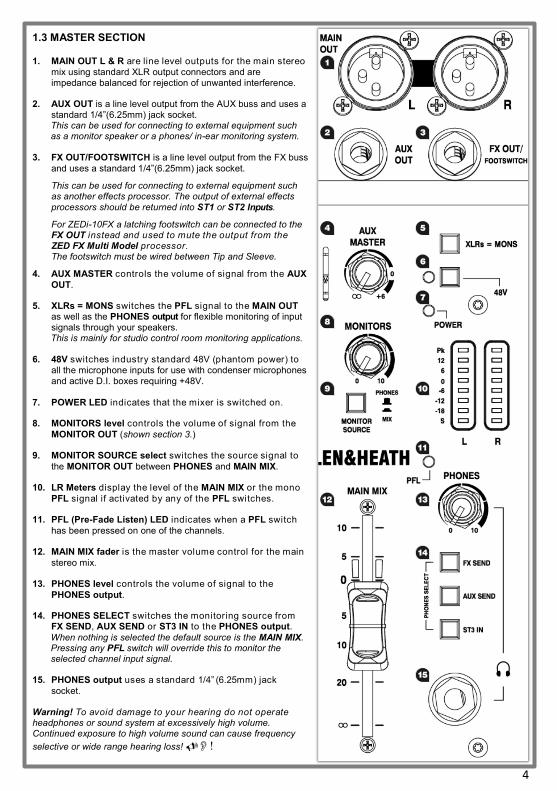
1.3 MASTER SECTION 1. MAIN OUT L & R are line level outputs for the main stereo
mix using standard XLR output connectors and are impedance balanced for rejection of unwanted interference.
2. AUX OUT is a line level output from the AUX buss and uses a standard 1/4”(6.25mm) jack socket. This can be used for connecting to external equipment such as a monitor speaker or a phones/ in-ear monitoring system.
3. FX OUT/FOOTSWITCH is a line level output from the FX buss
and uses a standard 1/4”(6.25mm) jack socket.
This can be used for connecting to external equipment such as another effects processor. The output of external effects
processors should be returned into ST1 or ST2 Inputs.
For ZEDi-10FX a latching footswitch can be connected to the FX OUT instead and used to mute the output from the ZED FX Multi Model processor. The footswitch must be wired between Tip and Sleeve.
4. AUX MASTER controls the volume of signal from the AUX
OUT.
5. XLRs = MONS switches the PFL signal to the MAIN OUT as well as the PHONES output for flexible monitoring of input signals through your speakers. This is mainly for studio control room monitoring applications.
6. 48V switches industry standard 48V (phantom power) to all the microphone inputs for use with condenser microphones and active D.I. boxes requiring +48V.
7. POWER LED indicates that the mixer is switched on.
8. MONITORS level controls the volume of signal from the
MONITOR OUT (shown section 3.)
9. MONITOR SOURCE select switches the source signal to
the MONITOR OUT between PHONES and MAIN MIX.
10. LR Meters display the level of the MAIN MIX or the mono
PFL signal if activated by any of the PFL switches.
11. PFL (Pre-Fade Listen) LED indicates when a PFL switch
has been pressed on one of the channels.
12. MAIN MIX fader is the master volume control for the main
stereo mix.
13. PHONES level controls the volume of signal to the
PHONES output.
14. PHONES SELECT switches the monitoring source from FX SEND, AUX SEND or ST3 IN to the PHONES output.
When nothing is selected the default source is the MAIN MIX. Pressing any PFL switch will override this to monitor the selected channel input signal.
15. PHONES output uses a standard 1/4” (6.25mm) jack
socket.
Warning! To avoid damage to your hearing do not operate headphones or sound system at excessively high volume. Continued exposure to high volume sound can cause frequency
selective or wide range hearing loss! !

5
2.1 EFFECTS SECTION
Effects such as reverb and delay are generally used to add “natural sounding” acoustics and
a sense of space to the mix, but can also be used to add interesting repetitions in time with
the music. Modulation effects can be used to enhance a sound harmonically or to add depth
and motion.
1. The ZED FX Multi Model processor is a high quality built-in effects unit which is fed with
a mono signal from the FX buss.
2. FX Select / Parameter control is used to scroll through effects presets and make
changes to editable parameters.
3. TAP TEMPO Button can be used to adjust the frequency or tempo of delay effects
that include a Tap Tempo parameter. If a delay effect is selected then you will see a
flashing decimal point on the right hand side of the preset display.
Change effects parameters by pressing and holding down the TAP TEMPO button
and turning the effects FX Select / Parameter control. The display will show a parameter
value of P0 to P9.
Reset the editable effects parameters to factory defaults, by holding down FX
Select / Parameter control and TAP TEMPO Button at the same time whilst
switching on the power.
Turn off the internal effects by setting the ZED FX Multi Model preset to “ 00”.
4. FX TO AUX controls the level of effects signal sent to the aux buss and AUX OUT from
the ZED FX Multi Model processor
5. FX to MIX rotary fader controls the volume of the stereo (wet) effects signal into
the MAIN MIX.
ST2 Inputs are routed to the MAIN MIX via the FX MIX control and are intended as
a stereo return channel for external effects processors, but can be used as an input for
other stereo sources when the ZED FX Multi Model is not in use.
A latching footswitch can be connected to the FX OUT (see section 1.3) and used to mute
the output from the ZED FX Multi Model processor. The footswitch must be wired between
Tip and Sleeve.
For more information on using the ZED FX Multi Model processor see section 6.4 .
2. ZED FX Multi Model Processor
(ZEDi-10FX only)

6
3.1 USB AUDIO INTERFACE
A built-in 4 in, 4 out, 24-bit/96kHz USB Audio Interface allows for studio-quality recording direct from your mixer to your PC without the need of any additional equipment. This is class-compliant (plug-and-play) for Mac and iOS devices. (iOS devices require a camera connection kit). Simply connect a USB cable between the USB port on the mixer and the USB port on your computer or device.
For Windows systems, driver software must be installed in order for it to work. The latest drivers and documentation can be found at www.allen-heath.com/downloads
1. MONITOR OUT is an unbalanced stereo line level output using standard RCA phono sockets. This could be used for connecting to external equipment such as monitor speakers or a phones/ in-ear monitoring system.
2. USB connector is a Type-B USB connector for multi-channel bi-directional audio streaming between the mixer and a computer and follows the high speed USB 2.0 standard.
3. USB OUT SOURCE SELECT buttons allow you to chose where the signal to the
outputs of the USB interface output is taken from.
M1 - M2 - AUX - FX selects the USB OUT source from channels M1, M2 and the AUX and FX buss outputs and has priority over the default M1 - M2 - M3 - M4 source
select.
M1 - M2 - L - R selects the USB OUT source from channels M1, M2 & MAIN MIX
and has priority over the M1 - M2 - AUX - FX source select switch.
If neither of these buttons are selected the default channel USB OUT source is taken
directly from channels M1 - M2 - M3 - M4.
4. ST2 and ST3 to AUX send control the level of signal sent to the AUX OUT. This
is useful for routing USB IN 1-2 and USB IN 3-4 to the PHONES or MONITOR OUT
5. ST2 & ST3 MIX rotary faders control the volume of the USB IN 1-2 or USB IN 3-4
signals into the MAIN MIX respectively.
3. ZEDi USB Audio Interface
3.2 Troubleshooting USB Audio Interface problems Playback and recording problems when using the ZEDi USB Audio Interface can be avoided by following the steps
below:
Minimum System Requirements: Ensure that your PC exceeds the Minimum System Requirements of the Digital Audio Workstation software that you are using to guarantee reliable performance and recording without pops, clicks, dropouts, or distortion in audio.
Latest Driver Software: For Windows systems it’s best to have the latest driver software installed.
Go to http://www.allen-heath.com/downloads for the latest driver software and documentation.
Audio Buffer Size: The audio buffer setting helps avoid pops, clicks, and dropouts by processing audio in blocks, but can also cause latency, a delay in the time it takes for audio to be processed and recorded or played back. Ideally the buffer size should be set as low as possible to minimize latency, whilst avoiding pops, clicks, and dropouts.
USB Hubs: Sharing USB ports via a hub may cause a reduction in the USB bandwidth available to the Audio
Interface. It’s best to connect audio interfaces directly to the USB port on your PC.
Ground Loops and Hum: Mains Ground Loops which cause low frequency noise or hum between audio devices can be avoided by powering devices from the same mains outlet via a suitable multi-socket extension. If you’re still experiencing this try disconnecting your laptop power supply as they are commonly the cause. Where possible, using balanced audio cables will also help.
Feedback Loops: It’s possible to create an internal feedback loop between the mixer and DAW software when recording the L-R stereo mix. Beware of returning monitoring signals from your DAW to the mix as the feedback can build up very quickly and potentially damage speakers or other equipment. Either mute the record-enabled channels in the DAW or turn down the MIX control on the USB IN channel and use PFL to monitor the signal from the DAW.
!

7
4.1 “Zeroing”
It’s good practice to “zero” your mixer and turn down relevant channels before connecting any devices as this prevents potential damage to speakers or other equipment.
Follow these steps to make sure you’re safe and you avoid thumps and bangs when plugging equipment in.
Speakers should always be switched ON LAST and OFF FIRST!
1. Make sure the power switch on the rear of the mixer is set to “OFF”
2. Connect the AC Mains Lead provided to the AC MAINS IN socket on the rear of the
mixer.
Check that the correct mains plug is fitted for your country and plug the AC Mains Lead into a standard household mains socket.
3. Turn channel Gain controls all the way down (left).
4. Make sure Instrument, HPF, PFL and 48V switches are not pressed in.
5. Set all channel EQ and PAN controls to the centre position marked “”
6. Turn all FX send, AUX send and MIX controls all the way down (left).
7. Lower the MAIN MIX fader to “∞”.
8. Turn down the PHONES level.
9. Double check speakers or amplifiers are switched off!
10. Connect speakers, instruments and other equipment.
11. Switch on instruments and other equipment, then the mixer, THEN speakers or amps!
Speaker or amp volumes should be set according to manufacturer guidelines. !
4. Good Practice
5.1 Connecting Microphones
Dynamic or condenser microphones and DI boxes should be connected to the Mic Input
Socket using a balanced XLR Microphone cable.
If you‘re using a condenser microphone, it will require 48V Phantom Power to work.
Some active DI boxes may also require phantom power.
Avoid ‘hot plugging’ when connecting any equipment and make sure AUX MASTER and MAIN MIX
controls are turned down before 48V is switched on as this as may cause loud thumps and bangs!
5.2 Connecting Instruments and Line-Level Equipment
High-Impedance (Hi-Z) instruments such as electro-acoustic guitars, basses and other Direct Input instruments should be connected to Line / Inst Inputs on channels M1 & M2 using a jack to jack instrument cable, and do not require an additional DI box or preamp. The Instrument switch must be activated to match extremely high impedance signals (10MΩ)
from instrument pickups.
Line level instruments such as keyboards, synthesizers, drum machines or equipment such as external effect processors can be connected to Line / Inst Inputs on channels M1 & M2, and LINE inputs on M3 & M4 for mono sources or ST1 & ST2 for stereo sources.
For channels M3 & M4 the LINE/PAD switch must be activated.
Follow the application examples in Section 7. for connecting devices to relevant input and outputs.
5. Connect mics, instruments and other equipment
8
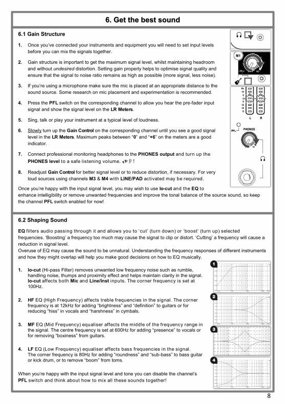
6.1 Gain Structure
1. Once you’ve connected your instruments and equipment you will need to set input levels
before you can mix the signals together.
2. Gain structure is important to get the maximum signal level, whilst maintaining headroom
and without undesired distortion. Setting gain properly helps to optimise signal quality and
ensure that the signal to noise ratio remains as high as possible (more signal, less noise).
3. If you’re using a microphone make sure the mic is placed at an appropriate distance to the
sound source. Some research on mic placement and experimentation is recommended.
4. Press the PFL switch on the corresponding channel to allow you hear the pre-fader input
signal and show the signal level on the LR Meters.
5. Sing, talk or play your instrument at a typical level of loudness.
6. Slowly turn up the Gain Control on the corresponding channel until you see a good signal
level in the LR Meters. Maximum peaks between “0” and “+6” on the meters are a good
indicator.
7. Connect professional monitoring headphones to the PHONES output and turn up the
PHONES level to a safe listening volume. !
8. Readjust Gain Control for better signal level or to reduce distortion, if necessary. For very
loud sources using channels M3 & M4 with LINE/PAD activated may be required.
Once you’re happy with the input signal level, you may wish to use lo-cut and the EQ to
enhance intelligibility or remove unwanted frequencies and improve the tonal balance of the source sound, so keep
the channel PFL switch enabled for now!
6. Get the best sound
6.2 Shaping Sound
EQ filters audio passing through it and allows you to ‘cut’ (turn down) or ‘boost’ (turn up) selected
frequencies. ‘Boosting’ a frequency too much may cause the signal to clip or distort. ‘Cutting’ a frequency will cause a
reduction in signal level.
Overuse of EQ may cause the sound to be unnatural. Understanding the frequency responses of different instruments
and how they might overlap will help you make good decisions on how to EQ musically.
1. lo-cut (Hi-pass Filter) removes unwanted low frequency noise such as rumble, handling noise, thumps and proximity effect and helps maintain clarity in the signal. lo-cut affects both Mic and Line/Inst inputs. The corner frequency is set at
100Hz.
2. HF EQ (High Frequency) affects treble frequencies in the signal. The corner frequency is at 12kHz for adding “brightness” and “definition” to guitars or for reducing “hiss” in vocals and “harshness” in cymbals.
3. MF EQ (Mid Frequency) equaliser affects the middle of the frequency range in the signal. The centre frequency is set at 600Hz for adding “presence” to vocals or for removing “boxiness” from guitars.
4. LF EQ (Low Frequency) equaliser affects bass frequencies in the signal. The corner frequency is 80Hz for adding “roundness” and “sub-bass” to bass guitar or kick drum, or to remove “boom” from toms.
When you’re happy with the input signal level and tone you can disable the channel’s
PFL switch and think about how to mix all these sounds together!

9
6.3 Balancing the Mix
Once you have set input gain levels and applied EQ to source signals, you can start to mix all of your channels to the outputs. Consider the importance of each instrument and how they should be heard in
the mix.
1. Make sure all PFL switches on your mixer are disabled to show MAIN MIX metering in LR Meters.
2. Slowly raise the MAIN MIX fader to around “0”.
3. Turn up channel MIX controls to send their signal to the main mix.
4. You will see the signal level displayed in the LR Meters.
5. As you mix the signals together you will see the combined level getting higher in the meters.
6. Avoid clipping and leave headroom for any louder moments in the program material.
Average peaks around “ 0” on the meters are a good indicator.
Maintain a natural sounding balance and relationship between voices and instruments. i.e. which instruments should be heard more clearly over others.
If you find that MIX controls are turned up very high and signal is still low, or MIX control is very low but signal is too high, readjust channel Gain and EQ controls to improve gain structure and tone
(see section 6.1)
8. Use PAN and balance to separate sounds and give instruments space in the mix or a realistic impression of where they might sit in the stereo image. Ideally, high energy LF sounds such as kick drum should be kept centre to distribute them evenly and share the load between speakers.
6.4 Applying Effects to the Mix (ZEDi-10FX only)
Before adding effects think about whether you want it to sound as though the voice or instruments are in a certain
performance space, if you want to add repetition effects such as echo (delay) or if you want them to sound like they do
on that classic album.
Using too much of an effect may mean losing definition or intelligibility of the original sound!
1. Select the desired effect preset and turn the FX Select / Parameter control to that number.
2. Press PFL on the channel and on the effects section to monitor (dry) channel signal and (wet)
effect return via the PHONES output before adding to the MAIN MIX.
3. If you have selected a delay effect and there’s a flashing decimal point on the preset display,
use the TAP TEMPO Button to bring the effect in time with program material.
4. Turn up the FX send on the channel until you hear the desired amount of effect.
The channel MIX control must be turned up because the FX send is post-fader.
5. Repeat this for any additional channels.
6. Once you’re happy with the sound disable all PFL switches.
7. Slowly turn up the effects MIX control to “0” to add the effects signal to the MAIN MIX.
8. Readjust channel FX send controls, if necessary!
Sending too much signal to a regenerative delay or using too much regeneration can cause sound
to build up very quickly, caution is advised! !

10
7. Application examples
Live
Microp
hon
eElectro A
cou
stic G
uitar Electron
ic Pian
o
Pow
ered P
A Sp
eakers
iPad
We
dge M
onitor
Bass G
uitar
Microp
hon
e
Extern
al FX Unit
Pho
nes / IEM
M
onito
ring

11
Studio
Electro Aco
ustic
Guitar
Electronic P
iano
Active Stud
io
Mo
nitors
Bass G
uitar
Dyn
amic o
r C
ond
enser M
icroph
one
Dru
m M
achine
PC
Pho
nes
Mo
nitorin
g
Refe
rence
Mo
nitors
Dyn
amic o
r C
ond
enser M
icroph
one
Extern
al FX Unit *
*Requires available
stereo return ch
annel

12
Water and moisture:
Do not expose the mixer to rain or moisture or use it in damp or wet conditions. Do not place containers of liquids on it which might spill into any openings.
Ventilation: Do not obstruct the ventilation slots or position the mixer where the air flow required for ventilation is impeded. If the mixer is to be placed in a rack unit or flight case ensure that it is well ventilated.
Heat and vibration: Do not place the mixer where it is subject to excessive heat or direct sunlight. Keep the mixer away from any equipment which produces excessive heat or vibration.
Servicing: Switch off equipment and unplug the power cord immediately if it is exposed to moisture, spilled liquid, objects fallen into the openings, if the power cord or plug have become damaged, during lightning storms, or if smoke, odour or abnormal noise is noticed.
Refer servicing to qualified technical personnel only.
Installation:
Install the mixer in accordance with the instructions printed in this User Guide. Do not connect the output of power amplifiers directly to the mixer. Only use audio connectors and plugs for their intended purpose.
Read instructions:
Retain these safety and operating instructions for future reference. Adhere to all warnings printed here and on the mixer and follow the operating instructions printed in this User Guide.
Do not remove cover:
Never operate the mixer if the cover is not correctly fitted.
Power sources:
Only connect the console to mains power of the type described in this User Guide and marked on the rear panel. Use a power cord with sealed mains plug appropriate for your local mains supply as provided with the mixer. If the provided plug does not fit into mains your outlet consult your service agent for assistance.
Power cord routing: Run the power cord so that it is out of the way and not likely to be walked on, stretched or pinched by items placed upon or against it.
Grounding:
Never remove or tamper with the ground connection or polarity in the power cord.
8. Important Safety Precautions
For all additional information such as hardware specification, product information or technical support please go to
http://www.allen-heath.com
A limited one year manufacturer’s warranty applies to this product, the conditions of the warranty can be found at http://www.allen-heath.com/legal
For service or support in your local area please go to http://www.allen-heath.com/where-to-buy and search for the country you are in.
Please register this product at http://www.allen-heath.com/register to receive useful information from time to
time.
ZEDi-10FX User Guide AP10147 Issue 1
Copyright © 2015 Allen & Heath Limited. All rights reserved.
Allen & Heath Limited, Kernick Industrial Estate, Penryn, Cornwall, TR10 9LU, UK
Additional Information