ZE motor-protective relay - Dominion Industrial GmbH Industrieautomation ... The ZE motor protection...
38
A Think future. Switch to green. Building Automation Systems Industrial Automation Hardware and Engineering 02/02 AWB2300-1425GB ZE motor-protective relay Overload monitoring of EEx e motors
Transcript of ZE motor-protective relay - Dominion Industrial GmbH Industrieautomation ... The ZE motor protection...
Moeller GmbH Industrieautomation Hein-Moeller-Straße 7–11 D-53115 Bonn E-Mail: [email protected] Internet: www.moeller.net
© 2002 by Moeller GmbHSubject to alterationAWB2300-1425GB IAB-MD/IAB-MD/Ki 02/02Printed in the Federal Republic of Germany (09/04)Article No.: xxxxxx
4 *patpks#nmvc-v*
A AThink future. Switch to green. Think future. Switch to green.
Building Automation SystemsIndustrial Automation
Hardware and Engineering
02/02 AWB2300-1425GB
ZE motor-protective relay Overload monitoring of EEx e motors
Rückenbreite entfällt

All brand and product names are trademarks or registered trademarks of the owner concerned.
1st published 2002, edition date 02/02
© Moeller GmbH, 53105 Bonn
Author: Wolfgang Nitschky Editor: Heidrun Riege Translator: Patrick Chadwick
All rights reserved, including those of the translation.
No part of this manual may be reproduced in any form (printed, photocopy, microfilm or any other process) or processed, duplicated or distributed by means of electronic systems without written permission of Moeller GmbH, Bonn.
Subject to alteration without notice.
Rückenbreite entfällt
Moe
llerG
mbH
Safe
ty in
stru
ctio
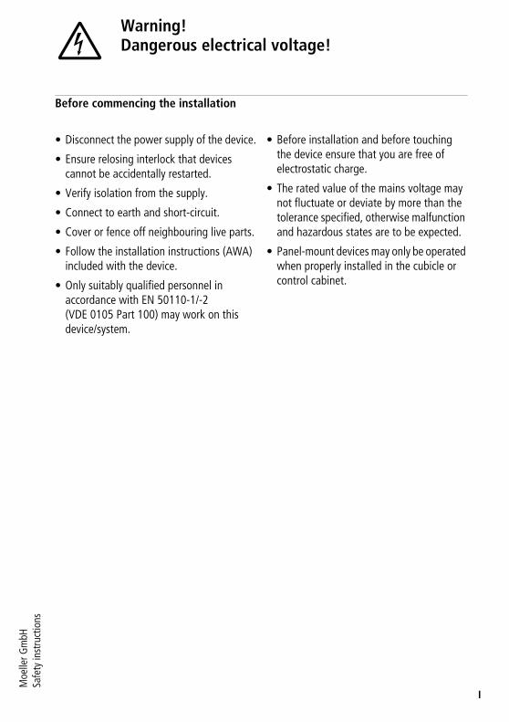
nsWarning!Dangerous electrical voltage!
I
Before commencing the installation
• Disconnect the power supply of the device.
• Ensure relosing interlock that devices cannot be accidentally restarted.
• Verify isolation from the supply.
• Connect to earth and short-circuit.
• Cover or fence off neighbouring live parts.
• Follow the installation instructions (AWA) included with the device.
• Only suitably qualified personnel in accordance with EN 50110-1/-2 (VDE 0105 Part 100) may work on this device/system.
• Before installation and before touching the device ensure that you are free of electrostatic charge.
• The rated value of the mains voltage may not fluctuate or deviate by more than the tolerance specified, otherwise malfunction and hazardous states are to be expected.
• Panel-mount devices may only be operated when properly installed in the cubicle or control cabinet.

II
02/02 AWB2300-1425GB
Contents
1
About this manual 3Target group 3Abbreviations and symbols 3
1 Motor protection relay ZE 5Preface 5Overview of the devices 6Device description 6– Overload protection relays with
bimetallic release 6– Current ranges for ZE relays 7– Temperature compensation 8– Phase loss 8– Reset 9– Test function 10
2 Configuration 11Monitoring overload of motors in the EEx e area 11Adjusting the overload current protection 11Short-circuit protection of the motor protection relay 12Approvals 13
3 Installation 15Notes on installation 15Mounting the devices 17
4 Operating the devices 19Settings 19– Reset 19– Test 19

Contents
2
02/02 AWB2300-1425GB
Appendix 21ZE nameplates 21ZE tripping characteristics 23– ZE-0,16 23– ZE-0,24 24– ZE-0,4 25– ZE-0,6 26– ZE-1,0 27– ZE-1,6 28– ZE-2,4 29– ZE-4 30– ZE-6 31– ZE-9 32– ZE-12 33
02/02 AWB2300-1425GB
3
About this manual
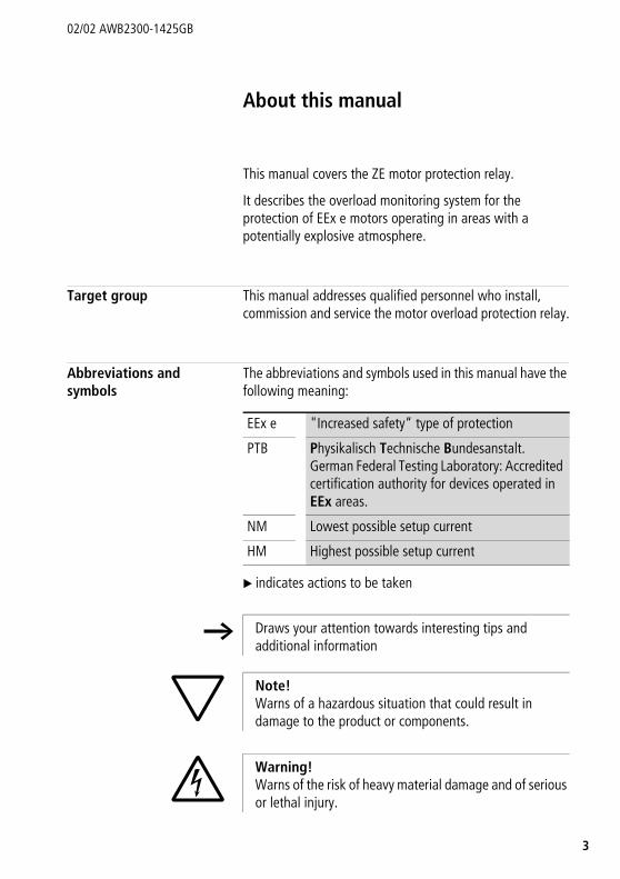
This manual covers the ZE motor protection relay.
It describes the overload monitoring system for the protection of EEx e motors operating in areas with a potentially explosive atmosphere.
Target group This manual addresses qualified personnel who install, commission and service the motor overload protection relay.
Abbreviations and symbols
The abbreviations and symbols used in this manual have the following meaning:
X indicates actions to be taken
EEx e "Increased safety“ type of protection
PTB Physikalisch Technische Bundesanstalt. German Federal Testing Laboratory: Accredited certification authority for devices operated in EEx areas.
NM Lowest possible setup current
HM Highest possible setup current
h Draws your attention towards interesting tips and additional information
Note!Warns of a hazardous situation that could result in damage to the product or components.
Warning!Warns of the risk of heavy material damage and of serious or lethal injury.

About this manual
4
02/02 AWB2300-1425GB
The chapter title in the header on the left side and the title of the current topic on the right side provide you with a good overview of this documentation. Exceptions are the starting pages of the chapters and empty pages at the end of a chapter.
02/02 AWB2300-1425GB
5
1 Motor protection relay ZE
Preface In addition to the type of protection specified in the standards EN 60079-14 and VDE 0165 Part 1, further provisions have been made to ensure safety from ignition for motors operated in potentially explosive atmospheres. EN 50019 demands additional measures for operating motors with "increased safety" type of protection "e". These measures provide a higher degree of safety and prevent impermissible high temperature and development of sparking and arcing on the motors, which usually does not occur under normal operating conditions. The motor protection equipment used for this is operated at a location separate from the EEx e area and must be certified by an accredited certification authority.
The guidelines on the application of Directive 94/9/EC (ATEX 100a) on the harmonization of the laws of the Member States concerning equipment and protection systems intended for use in potentially explosive atmospheres became mandatory from 30 June 2003.
The ZE motor protection system is approved by the PTB in accordance with the Directive 94/9/EC (ATEX 100a).
h The EC Type Examination Certificate Number is: PTB 01 ATEX 3331
((

Motor protection relay ZE
6
02/02 AWB2300-1425GB
Overview of the devices
Figure 1: Motor protection relay ZE
a Device nameplateb Wheel for setting motor currentc OFF button, testd Reset knob, reset lock-out
Device description Overload protection relays with bimetallic release
The ZE motor protection relays are 3-pole electromechanical motor circuit breakers using bimetallic elements. They are suitable for monitoring both DC and AC currents. Type ZE motor protection relays have been designed to be fitted directly on to DILEEM and DILEM contactors,
In the event of overload tripping, the auxiliary contacts 95-96 and 97-98 change over and disconnect the control voltage circuit from the corresponding contactor relay, and thus indirectly switch off the current to the motor being monitored. (a following Fig. 2)
a
d
c
b
Device description02/02 AWB2300-1425GB
7
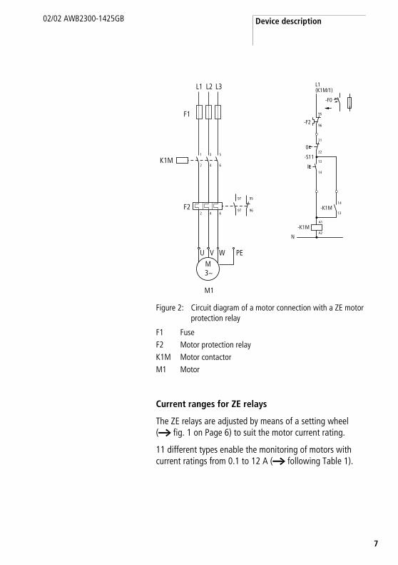
Figure 2: Circuit diagram of a motor connection with a ZE motor protection relay
F1 FuseF2 Motor protection relayK1M Motor contactorM1 Motor
Current ranges for ZE relays
The ZE relays are adjusted by means of a setting wheel (a fig. 1 on Page 6) to suit the motor current rating.
11 different types enable the monitoring of motors with current ratings from 0.1 to 12 A (a following Table 1).
M1
M
U V W
F2
F1
L1 L2 L3
K1M
2 4 6
2 4 6
97
97
95
96
1 3 5
PE
3~
L1(K1M/1)
95
96
21
22
13
14
-F2
0
-S11
I
13
14-K1M
A1
A2-K1M
N
-F0
Motor protection relay ZE
8
02/02 AWB2300-1425GB
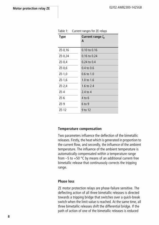
Table 1: Current ranges for ZE relays
Temperature compensation
Two parameters influence the deflection of the bimetallic releases. Firstly, the heat which is generated in proportion to the current flow, and secondly, the influence of the ambient temperature. The influence of the ambient temperature is automatically compensated within a temperature range from –5 to +50 °C by means of an additional current-free bimetallic release that continuously corrects the tripping range.
Phase loss
ZE motor protection relays are phase-failure sensitive. The deflecting action of all three bimetallic releases is directed towards a tripping bridge that switches over a quick-break switch when the limit value is reached. At the same time, all three bimetallic releases shift the differential bridge. If the path of action of one of the bimetallic releases is reduced
Type Current range Ie A
ZE-0,16 0.10 to 0.16
ZE-0,24 0.16 to 0.24
ZE-0,4 0.24 to 0.4
ZE-0,6 0.4 to 0.6
ZE-1,0 0.6 to 1.0
ZE-1,6 1.0 to 1.6
ZE-2,4 1.6 to 2.4
ZE-4 2.4 to 4
ZE-6 4 to 6
ZE-9 6 to 9
ZE-12 9 to 12
Device description02/02 AWB2300-1425GB
9
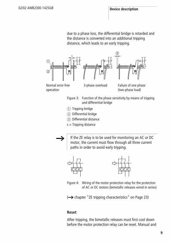
due to a phase loss, the differential bridge is retarded and the distance is converted into an additional tripping distance, which leads to an early tripping.
Figure 3: Function of the phase sensitivity by means of tripping and differential bridge
a Tripping bridgeb Differential bridgec Differential distances = Tripping distance
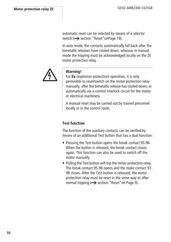
Figure 4: Wiring of the motor protection relay for the protection of AC or DC motors (bimetallic releases wired in series)
(a chapter “ZE tripping characteristics” on Page 23)
Reset
After tripping, the bimetallic releases must first cool down before the motor protection relay can be reset. Manual and
Normal error-free operation
3-phase overload Failure of one phase(two-phase load)
97S
95
98 96
97 95
98 96
97 95
98 96
�
�
�
h If the ZE relay is to be used for monitoring an AC or DC motor, the current must flow through all three current paths in order to avoid early tripping.
Motor protection relay ZE
10
02/02 AWB2300-1425GB
automatic reset can be selected by means of a selector switch (a section “Reset”onPage 19).
In auto mode, the contacts automatically fall back after the bimetallic releases have cooled down, whereas in manual mode the tripping must be acknowledged locally on the ZE motor protection relay.
Test function
The function of the auxiliary contacts can be verified by means of an additional Test button that has a dual function:
• Pressing the Test button opens the break contact 95-96. When the button is released, the break contact closes again. This function can also be used to switch off the motor manually.
• Pulling the Test button will trip the motor protection relay. The break contact 95-96 opens and the make contact 97-98 closes. After the Test button is released, the motor protection relay must be reset in the same way as after normal tripping (a section “Reset”on Page 9).
Warning!For Ex (explosion protection) operation, it is only permisible to reset/switch on the motor protection relay manually, after the bimetallic release has cooled down, or automatically via a control interlock circuit for the motor or electrical machinery.
A manual reset may be carried out by trained personnel locally or in the control room.
1
02/02 AWB2300-1425GB
1
2 Configuration
Monitoring overload of motors in the EEx e area
Special design features are implemented so that motors can achieve the ignition protection rating EEx e. The motors are assigned to temperature classes on the basis of the highest permissible surface temperature. The temperature rise time tE and the ratio between startup current and rated current IA/IN are calculated also and specified on the rating plate of the motor.
The temperature rise time tE represents the time required for the temperature of the motor winding to rise from its final rated operational temperature up to the limit temperature, at a startup current of IA.
However, since EEx e motors are not intrinsically safe, explosion safety is only achieved by taking special measures during installation and by selecting appropriate operating conditions (PTB testing regulations), e.g. by a combination of the circuit with a correctly rated and set overload current protection.
Adjusting the overload current protection
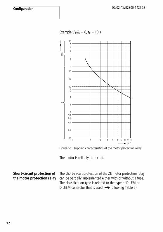
Warning!The selected current overload protection system must not only ensure proper motor current monitoring, but also that a blocked motor is switched off within the temperature rise time tE. This means, the protective device must be rated in such a way to ensure that the tripping time tA for the ratio IA/IN of the EEx e motor is not higher than its temperature rise time tE according to its characteristic curve, in order safely to switch off the motor within that period (a following example).
Configuration
12
02/02 AWB2300-1425GB
Example: IA/IN = 6, tE = 10 s
Figure 5: Tripping characteristics of the motor protection relay
The motor is reliably protected.
Short-circuit protection of the motor protection relay
The short-circuit protection of the ZE motor protection relay can be partially implemented either with or without a fuse. The classification type is related to the type of DILEM or DILEEM contactor that is used (a following Table 2).
10.1
0.2
0.4
0.60.8
1
2
4
68
10
20
40
1
2
4
68
10
2 3 4 5 6 7 8 9 10
�
min
s
� �
Approvals
3
02/02 AWB2300-1425GB
1
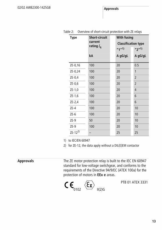
Table 2: Overview of short-circuit protection with ZE relays
1) to IEC/EN 609472) for ZE-12, the data apply without a DIL(E)EM contactor
Approvals The ZE motor protection relay is built to the IEC EN 60947 standard for low-voltage switchgear, and conforms to the requirements of the Directive 94/9/EC (ATEX 100a) for the protection of motors in EEx e areas.
Type Short-circuit current rating Iq
With fusing
Classification type
“1”1) “2”1)
kA A gG/gL A gG/gL
ZE-0,16 100 20 0.5
ZE-0,24 100 20 1
ZE-0,4 100 20 2
ZE-0,6 100 20 2
ZE-1,0 100 20 4
ZE-1,6 100 20 6
ZE-2,4 100 20 6
ZE-4 100 20 10
ZE-6 100 20 10
ZE-9 50 20 10
ZE-9 100 20 10
ZE-122) – 25 25
c PTB 01 ATEX 3331
0102 II(2)G

Configuration
14
02/02 AWB2300-1425GB
The system is approved by UL and CSA for the USA and Canada.
Further approvals exist for
U s
• Romania
• Russia
• China
• Slovak Republic
ML PAT

5
02/02 AWB2300-1425GB
1
3 Installation
Notes on installation
h For the mechanical and electrical installation, the Installation Instructions AWA23-883 on the inside of the packaging must be observed.
Warning!For Ex (explosion protection) operation, it is only permisible to reset/switch on the motor protection relay manually, after the bimetallic release has cooled down, or automatically via a control interlock circuit for the motor or electrical machinery.
A manual reset may be carried out by trained personnel locally or in the control room.
Warning!Particularly in EEx e applications, an automatic restart must be prevented after an interruption and restoration of the control voltage. This is prevented safely by means of the latching function of the power relay.
Installation
16
02/02 AWB2300-1425GB
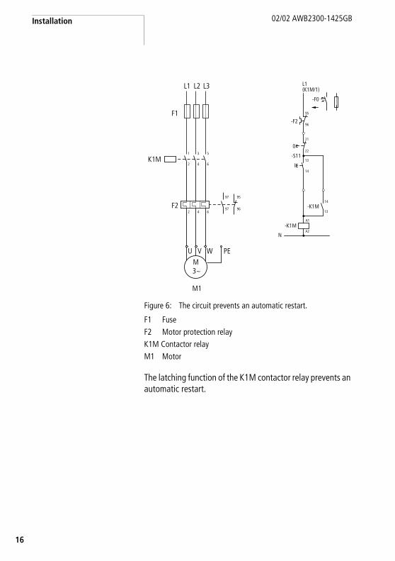
Figure 6: The circuit prevents an automatic restart.
F1 FuseF2 Motor protection relayK1M Contactor relayM1 Motor
The latching function of the K1M contactor relay prevents an automatic restart.
M1
M
U V W
F2
F1
L1 L2 L3
K1M
2 4 6
2 4 6
97
97
95
96
1 3 5
PE
3~
L1(K1M/1)
95
96
21
22
13
14
-F2
0
-S11
I
13
14-K1M
A1
A2-K1M
N
-F0

Mounting the devices
7
02/02 AWB2300-1425GB
1
Mounting the devices X Mount the ZE motor protection relay on the DIL(E)EM contactor.
Figure 7: Assembly of DIL(E)EM and ZE
X Both can be mounted in any position, apart from as shown in Fig. 8.
Figure 8: Impermissible mounting positions for DIL(E)EM and ZE
A1, A2 coil connections
1.2 Nm
Z 2
A2 A1
Installation
18
02/02 AWB2300-1425GB
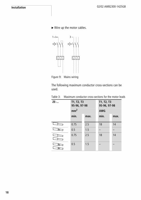
X Wire up the motor cables.
Figure 9: Mains wiring
The following maximum conductor cross-sections can be used.
Table 3: Maximum conductor cross-sections for the motor leads
ZE-... T1, T2, T395-96, 97-98
T1, T2, T395-96, 97-98
mm2 AWG
min. max. min. max.
0.75 2.5 18 14
0.5 1.5 – –
0.75 2.5 18 14
0.5 1.5 – –
1h/H 3 ~
9
02/02 AWB2300-1425GB
1
4 Operating the devices
Settings Before commissioning the ZE relay, the rated current of the motor must be set, using the setting wheel on the ZE relay (a table 1 on Page 8).
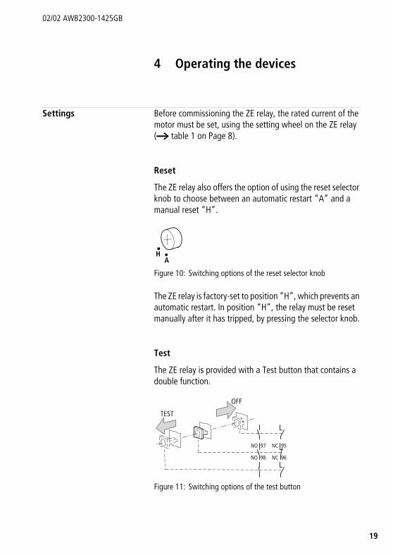
Reset
The ZE relay also offers the option of using the reset selector knob to choose between an automatic restart “A” and a manual reset “H”.
Figure 10: Switching options of the reset selector knob
The ZE relay is factory-set to position “H”, which prevents an automatic restart. In position “H”, the relay must be reset manually after it has tripped, by pressing the selector knob.
Test
The ZE relay is provided with a Test button that contains a double function.
Figure 11: Switching options of the test button
HA
TEST
NC 95
NC 96
NO 97
NO 98
OFF
Operating the devices
20
02/02 AWB2300-1425GB
Pressing the button opens the auxiliary contact 95-96, and this can be used to switch off the contactor.a fig. 11on Page 19
Warning!Faulty devices may not be opened for repairs and must be replaced only by skilled persons.
1
02/02 AWB2300-1425GB
2
Appendix
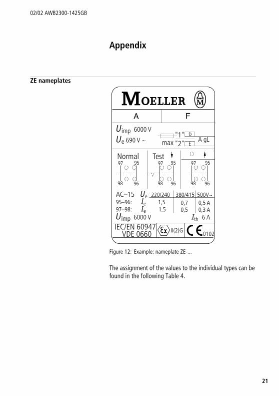
ZE nameplates
Figure 12: Example: nameplate ZE-...
The assignment of the values to the individual types can be found in the following Table 4.
�imp 6000 V
�imp 6000 V �th 6 A
�e 690 V �
Normal97 95
98 96
97 95
98 96
Test97 95
98 96
max A gL"1""2"
AC–15 �e 220/24095–96: �e 1,597–98: �e 1,5
380/415 500V�0,7 0,5 A0,5 0,3 A
IEC/EN 60947VDE 0660
D
E
II(2)G 0102
A F

Appendix
22
02/02 AWB2300-1425GB
Table 4: Values for individual types
A D E F
ZE-0,16 20 0.5 0.1 to 0.16 A
ZE-0,24 20 1 0.16 to 0.24 A
ZE-0,4 20 2 0.24 to 0.4 A
ZE-0,6 20 2 0.4 to 0.6 A
ZE-1,0 20 4 0.6 to 1.0 A
ZE-1,6 20 6 1.0 to 1.6 A
ZE-2,4 20 6 1.6 to 2.4 A
ZE-4 20 10 2.4 to 4 A
ZE-6 20 10 4 to 6 A
ZE-9 20 10 6 to 9 A
ZE-12 – – 9 to 12 A
ZE tripping characteristics
3
02/02 AWB2300-1425GB
2
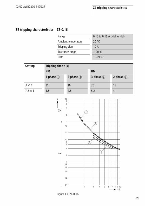
ZE tripping characteristics ZE-0,16
Figure 13: ZE-0,16
Range 0.10 to 0.16 A (NM to HM)
Ambient temperature 20 °C
Tripping class 10 A
Tolerance range g 20 %
Date 10.09.97
Setting Tripping time t [s]
NM HM
3-phase a 2-phase c 3-phase b 2-phase d
3 x I 21 16 20 13
7.2 x I 5.5 4.6 5.2 4
10.1
0.2
0.4
0.60.8
1
2
4
68
10
20
40
1
2
4
68
10
2 3 4 5 6 7 8 9 10
�
min
s
� �
�
�
�
�
Appendix
24
02/02 AWB2300-1425GB
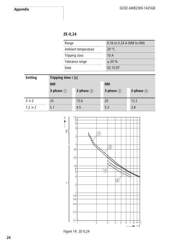
ZE-0,24
Figure 14: ZE-0,24
Range 0.16 to 0.24 A (NM to HM)
Ambient temperature 20 °C
Tripping class 10 A
Tolerance range g 20 %
Date 02.10.97
Setting Tripping time t [s]
NM HM
3-phase a 2-phase c 3-phase b 2-phase d
3 x I 24 15.6 20 12.2
7.2 x I 5.7 4.5 5.3 3.8
�
10.1
0.2
0.4
0.60.8
1
2
4
68
10
20
40
1
2
4
68
10
2 3 4 5 6 7 8 9 10
�
min
s
� �
�
�
�

ZE tripping characteristics
5
02/02 AWB2300-1425GB
2
ZE-0,4
Figure 15: ZE-0,4
Range 0.24 to 0.4 A (NM to HM)
Ambient temperature 20 °C
Tripping class 10 A
Tolerance range g 20 %
Date 06.10.97
Setting Tripping time t [s]
NM HM
3-phase a 2-phase c 3-phase b 2-phase d
3 x I 23 17 19 11.8
7.2 x I 5.5 4.8 4.9 3.8
10.1
0.2
0.4
0.60.8
1
2
4
68
10
20
40
1
2
4
68
10
2 3 4 5 6 7 8 9 10
�
min
s
� �
�
�
�
�

Appendix
26
02/02 AWB2300-1425GB
ZE-0,6
Figure 16: ZE-0,6
Range 0.4 to 0.6 A (NM to HM)
Ambient temperature 20 °C
Tripping class 10 A
Tolerance range g 20 %
Date 06.10.97
Setting Tripping time t [s]
NM HM
3-phase a 2-phase c 3-phase b 2-phase d
3 x I 27 19.5 25 15.5
7.2 x I 6.5 5.4 6.1 4.55
10.1
0.2
0.4
0.60.8
1
2
4
68
10
20
40
1
2
4
68
10
2 3 4 5 6 7 8 9 10
�
min
s
� �
�
�
�
�
ZE tripping characteristics
7
02/02 AWB2300-1425GB
2
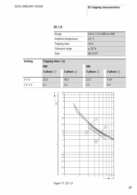
ZE-1,0
Figure 17: ZE-1,0
Range 0.6 to 1.0 A (NM to HM)
Ambient temperature 20 °C
Tripping class 10 A
Tolerance range g 20 %
Date 06.10.97
Setting Tripping time t [s]
NM HM
3-phase a 2-phase c 3-phase b 2-phase d
3 x I 25.5 18.5 22.5 13.9
7.2 x I 6.1 5.2 5.5 4.4
10.1
0.2
0.4
0.60.8
1
2
4
68
10
20
40
1
2
4
68
10
2 3 4 5 6 7 8 9 10
�
min
s
� �
�
�
�
�

Appendix
28
02/02 AWB2300-1425GB
ZE-1,6
Figure 18: ZE-1,6
Range 1.0 to 1.6 A (NM to HM)
Ambient temperature 20 °C
Tripping class 10 A
Tolerance range g 20 %
Date 06.10.97
Setting Tripping time t [s]
NM HM
3-phase a 2-phase c 3-phase b 2-phase d
3 x I 24 17 21 13
7.2 x I 5.6 4.4 4.9 3.6
10.1
0.2
0.4
0.60.8
1
2
4
68
10
20
40
1
2
4
68
10
2 3 4 5 6 7 8 9 10
�
min
s
� �
�
�
�
�

ZE tripping characteristics
9
02/02 AWB2300-1425GB
2
ZE-2,4
Figure 19: ZE-2,4
Range 1.6 to 2.4 A (NM to HM)
Ambient temperature 20 °C
Tripping class 10 A
Tolerance range g 20 %
Date 06.10.97
Setting Tripping time t [s]
NM HM
3-phase a 2-phase c 3-phase b 2-phase d
3 x I 24.7 18.1 21.7 13.7
7.2 x I 6 5 5.5 4.3
�
10.1
0.2
0.4
0.60.8
1
2
4
68
10
20
40
1
2
4
68
10
2 3 4 5 6 7 8 9 10
�
min
s
� �
�
�
�

Appendix
30
02/02 AWB2300-1425GB
ZE-4
Figure 20: ZE-4
Range 2.4 to 4 A (NM to HM)
Ambient temperature 20 °C
Tripping class 10 A
Tolerance range g 20 %
Date 29.06.01
Setting Tripping time t [s]
NM HM
3-phase a 2-phase c 3-phase b 2-phase d
3 x I 30.0 20.0 25.5 15.5
7.2 x I 6.8 5.2 6.1 4.4
10.1
0.2
0.4
0.60.8
1
2
4
68
10
20
40
1
2
4
68
10
2 3 4 5 6 7 8 9 10
�
min
s
� �
�
�
�
�

ZE tripping characteristics
1
02/02 AWB2300-1425GB
3
ZE-6
Figure 21: ZE-6
Range 4 to 6 A (NM to HM)
Ambient temperature 20 °C
Tripping class 10 A
Tolerance range g 20 %
Date 06.10.97
Setting Tripping time t [s]
NM HM
3-phase a 2-phase c 3-phase b 2-phase d
3 x I 26 18.1 24 15
7.2 x I 6.1 4.8 5.6 4
10.1
0.2
0.4
0.60.8
1
2
4
68
10
20
40
1
2
4
68
10
2 3 4 5 6 7 8 9 10
�
min
s
� �
�
�
�
�

Appendix
32
02/02 AWB2300-1425GB
ZE-9
Figure 22: ZE-9
Range 6 to 9 A (NM to HM)
Ambient temperature 20 °C
Tripping class 10 A
Tolerance range g 20 %
Date 08.10.97
Setting Tripping time t [s]
NM HM
3-phase a 2-phase c 3-phase b 2-phase d
3 x I 28.8 20.6 24.8 15.5
7.2 x I 5.7 4.5 4.9 3.6
10.1
0.2
0.4
0.60.8
1
2
4
68
10
20
40
1
2
4
68
10
2 3 4 5 6 7 8 9 10
�
min
s
� �
�
��
�
ZE tripping characteristics
3
02/02 AWB2300-1425GB
3
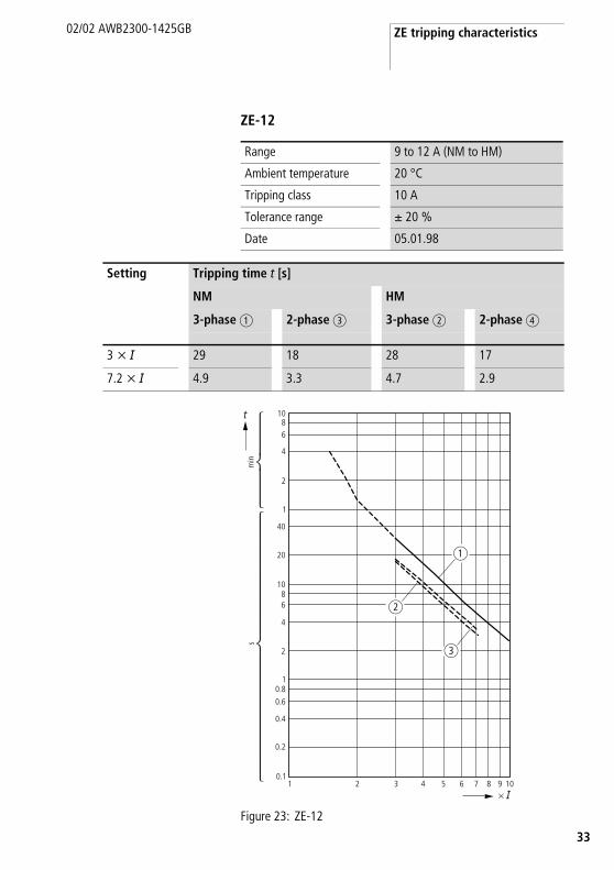
ZE-12
Figure 23: ZE-12
Range 9 to 12 A (NM to HM)
Ambient temperature 20 °C
Tripping class 10 A
Tolerance range g 20 %
Date 05.01.98
Setting Tripping time t [s]
NM HM
3-phase a 2-phase c 3-phase b 2-phase d
3 x I 29 18 28 17
7.2 x I 4.9 3.3 4.7 2.9
10.1
0.2
0.4
0.60.8
1
2
4
68
10
20
40
1
2
4
68
10
2 3 4 5 6 7 8 9 10
�
min
s
� �
�
�
�
Moeller GmbH Industrieautomation Hein-Moeller-Straße 7–11 D-53115 Bonn E-Mail: [email protected] Internet: www.moeller.net
© 2002 by Moeller GmbHSubject to alterationAWB2300-1425GB Doku/Doku/Ki 02/02Printed in the Federal Republic of Germany (09/04)Article No.: 286908
4 *patpks#,n.-,c*
A AThink future. Switch to green. Think future. Switch to green.
Building Automation SystemsIndustrial Automation
Hardware and Engineering
02/02 AWB2300-1425GB
ZE motor-protective relay Overload monitoring of EEx e motors
Rückenbreite entfällt