ZAU-84-104810-VA-5793-20001-0000-02-Scope of Work for CMMS and CCMS
143
-
Upload
pazhamalai-rajan -
Category
Documents
-
view
48 -
download
14
description
iuoyugfhfhnn dfhdrhgjmbvm cvncvncnm
Transcript of ZAU-84-104810-VA-5793-20001-0000-02-Scope of Work for CMMS and CCMS

Scope of work for CMMS and CCMS
Doc. No: ZAU-84-104810 -VA-6793-20001-0000
PAGE 2 of 5
REVISION: 02 Date: 03.06.2013
CONTENTS
1.0 Purpose 3
2.0 Scope 3
2.1 Scope of Work for Computerized Maintenance 3 Management System (CMMS) 2.2 Scope of Work for Completion Certification 5 Management System (CCMS 3.0 Codes and Standard 5
APPENDIX - I CMMS Asset and Activity Registration Procedure APPENDIX-I
APPENDIX - II Selection of Safety Critical Elements (SCE) and APPENDIX-II Development of Performance Stds (PS) & PS Assurance Tasks. APPENDIX - III Engineering and Operations Procedure for APPENDIX-III Z6 Notification APPENDIX - IV Criticality Assessment Procedure APPENDIX-IV
APPENDIX - V E-SPIR 2000 Procedure & Project Documents APPENDIX-V Requirement

Scope of work for CMMS and CCMS
Doc. No: ZAU-84-104810 -VA-6793-20001-0000
PAGE 3 of 5
REVISION: 02 Date: 03.06.2013
1.0 PURPOSE
The purpose of this document is to provide the clear scope of work for Computerized Maintenance Management System (CMMS) and Completion Certification Management System (CCMS) in order to proper loading to PDO SAP system for the Zauliyah Gas Plant project.
2.0 SCOPE
2.1 Scope of Work for Computerized Maintenance Management System (CMMS)
The scope of work for CMMS consists of basically three activities i.e. SAP PM, CIMS and E-SPIR. The detailed scope is given below.
Sl. No.
Description Remarks
01. SAP PM Pack 1 - Asset Resister: The scope for preparing asset data is collecting, verifying and formatting the asset data by referring to respective design drawings, various manuals, other relevant document sources.
- RBI workshop - RCM workshop - IPF workshop - SCE Identification Study ( After conducting RBI/RCM/IPF
and Design HSE case) The Asset Resister work should be carried out as per PDO document No. PR-1344 Rev 05 (Dec-2009). For Ref. Appendix I for this document.
02. SAP PM Pack 2 - SCE Identification: Identification and Data preparation for Safety Critical Elements (SCE) for SAP Upload as per EP-2009-9009 & guidelines. SAP PM template. Ref. Appendix II
- Function locations level 1-5 in SAP PM (using AFC drawings) - Equipment data - FLOCs classification - Equipment classification - SCE / performance standards - 25% CMMS review workshop (In presence of Project team +
UEPI 31) - MCPs in SAP (based on RCM Study) - Task list in SAP PM (based on RCM Study) - Maintenance plans/scheduling - 50% CMMS review workshop (In presence of PDO Operation
+Project +UEPI31+CDFP)

Scope of work for CMMS and CCMS
Doc. No: ZAU-84-104810 -VA-6793-20001-0000
PAGE 4 of 5
REVISION: 02 Date: 03.06.2013
- Z6 Creation. Refer PDO DOC. No. PR-1528, Rev 03 (Sep, 2009). For details refer Appendix III
- Z6 Review and Approval - Asset Registration - 75% CMMS review workshop (In Presence of PDO Operation
+Project +UEPI31) - 100% CMMS Review.
03. SAP PM Pack 3 -RCM & RBI Study: Appropriate pro-active maintenance (PM) tasks are selected on the basis of a criticality assessment as per doc no PR-1248 Version 02 July’2000. For detail ref. Appendix IV
PR 1248
04. SAP PM Pack 4 - Asset Maintenance Plan Deliverable: Further, for every asset maintenance plan, data to be prepared based on the output of RCM&RBI study.
05. Corrosion inspection Management System (CIMS): In addition to PDO SAP system registration (i.e. Plant Maintenance Planning and Inspection scheduling), CIMS master data for all static & Piping equipment need to be prepared for CORROSION MONITORING and CORROSION ANLYSIS requirements.
- Provide CIMS Template - CIMS Data Population (based on RBI Study) - CIMS Data Review and Approval - 75% CMMS Review Workshop (In-presence of PDO
Operation + Project + UEOC5 + Purchaser) - Carry out Baseline Survey - Log Baseline Actual Result in CIMS - Switch Gear Operating Procedures - 100% CMMS review workshop (before PSUA)
06. Electronic Spare Parts List and Interchangeability Record (E-SPIR): The spares data will be prepared as per SPIR form for ESPIR input. The data will be collected and prepared from related documents from EPC / Vendors. Spare parts list will be prepared as per PDO procedure PR-1443 Rev-2 June-09. For Details ref. Appendix V.
- Spare Parts. - E-SPIR data population - E-SPIR data review - E-SPIR data review / approval - SAP spares coding - Progress review - can be combined with 50% CMMS review - Bill of Materials (BOM) link to equipments. After function
location level 1-5 in SAP PM using AFC Drawings - Progress review - can be combined with 75% CMMS review

Scope of work for CMMS and CCMS
Doc. No: ZAU-84-104810 -VA-6793-20001-0000
PAGE 5 of 5
REVISION: 02 Date: 03.06.2013
Vender needs to co-ordinate with the individual vendors and the purchaser engineering team directly to get the required data. 2.2 Scope of Work for Completion Certification Management System (CCMS)
The detailed scope is given below. Sl. No.
Description Remarks
01. Identification of Area and Sub-area: Vender has to prepare the Area and Sub-area identification after discussing with purchaser engineering and commissioning team.
02. Preparation of Database (Xls file): Vendor need to prepare the database based on the engineering documents.
03 Uploading the database to PDO system: The database prepared in PDO format need to be uploaded in the PDO system.
04. Downloading of check sheets for Construction / Pre-commissioning / commissioning activity: Vendor need to download the check sheets form PDO server which needs to be required for purchaser’s Construction / Pre-commissioning / commissioning activity.
3.0 CODES AND STANDARDS
Following Codes and standards need to be followed by vendor:
PR-1032 Maintenance Plans Approval Procedure PR-1248 Criticality Assessment Procedure PR-1250 CIMS Manual PR-1344 Engineering and Operation - Asset and Activity Registration and Deletion in
SAP. PR-1416 Procedures for the Use of Pipe-RBI Methodology PR-1443 E-SPIR 2000 Procedure & Project Documents Requirement PR-1528 E-SPIR 2000 Procedure & Project Documents Requirement GU-558 Selection of Safety Critical Elements (SCE) and Development of Performance
Stds (PS) & PS Assurance Tasks
Scope of work for CMMS and CCMS
Doc. No: ZAU-84-104810 -VA-6793-20001-0000
APPENDIX-I
REVISION: 02 Date: 03.06.2013
APPENDIX I
Engineering and Operations- Asset and Activity Registration and Deletion in SAP

This document is the property of Petroleum Development Oman, LLC. Neither the whole nor any part of this document may be disclosed to others or reproduced, stored in a retrieval system, or transmitted in any form by any means (electronic, mechanical, reprographic recording or otherwise) without prior written consent of the owner.
Petroleum Development Oman L.L.C.
Engineering and Operations
Asset and Activity Registration and Deletion in
SAP
User Note:
The requirements of this document are mandatory. Non-compliance shall only be authorised by the Document Owner or his Delegate through STEP-OUT approval.
A controlled copy of the current version of this document is on PDO's EDMS. Before making reference to this document, it is the user's responsibility to ensure that any hard copy, or electronic copy, is current. For assistance, contact the Document Custodian or the Document Controller.
Users are encouraged to participate in the ongoing improvement of this document by providing constructive feedback.
Please familiarise yourself with the Document Security Classification Definitions
They apply to this Document!
UNRESTRICTED Document ID: PR-1344 Dec-09 Filing Key: Business Control
Petroleum Development Oman LLC Revision: 5.0 Effective: Dec-09
Page 2 PR-1344 - Asset and Activity Registration and Deletion in SAP
Printed 16/12/09
The controlled version of this CMF Document resides online in Livelink®. Printed copies are UNCONTROLLED.
This page was intentionally left blank

Petroleum Development Oman LLC Revision: 5.0 Effective: Dec-09
Page 3 PR-1344 - Asset and Activity Registration and Deletion in SAP
Printed 16/12/09
The controlled version of this CMF Document resides online in Livelink®. Printed copies are UNCONTROLLED.
i Document Authorisation Authorised For Issue – December 2009

Petroleum Development Oman LLC Revision: 5.0 Effective: Dec-09
Page 4 PR-1344 - Asset and Activity Registration and Deletion in SAP
Printed 16/12/09
The controlled version of this CMF Document resides online in Livelink®. Printed copies are UNCONTROLLED.
ii Revision History
The following is a brief summary of the 4 most recent revisions to this document. Details of all revisions prior to these are held on file by the issuing department. Revision No.
Date Author Scope / Remarks
5.0 Dec 09 Derek Maguire
Latent Limited Robin Norman UOP6
Procedure reviewed and updated to improve the understanding to projects and PDO Staff, of what is required to be uploaded into SAP for an effective Maintenance Management System. Checked format and reviewed Sections 2, 3 and 4 with inputs from UOM32
4.0 Sep 06 UOM/321 Procedure reviewed due to improved process work-flow and validated with extra related business control documents including deletion procedure.
3.0 Jul 03 TTO/32 Updated to SAP version
iii Related Business Processes
Code Business Process (EPBM 4.0)EP.64 Design, Construct, Modify and Decommission Facilities
EP.65 Execute Operations Readiness & Assurance Activities
EP.72 Maintain & Assure Facilities Integrity
EP.80 Manage Abandonment
iv Related Corporate Management Frame Work (CMF) Documents
The related CMF Documents can be retrieved from the CMF Business Control Portal.
CP-114 Maintenance and Integrity Management CoP
PR-1032 CMMS (SAP) - Maintenance Plans Creation & Approval Procedure
PR-1528 Z6 Notification
PR-1078 Lifting and Hoisting Procedure Inspection Testing and Certification Inspection
PR-1428 Functional Criticality Assessment Procedure
Petroleum Development Oman LLC Revision: 5.0 Effective: Dec-09
Page 5 PR-1344 - Asset and Activity Registration and Deletion in SAP
Printed 16/12/09
The controlled version of this CMF Document resides online in Livelink®. Printed copies are UNCONTROLLED.
TABLE OF CONTENTS 1 Introduction ............................................................................................................................ 9
1.1 Background ...................................................................................................................... 9 1.2 Purpose ............................................................................................................................ 9 1.3 Scope ............................................................................................................................... 9 1.4 Distribution / Target Audience .......................................................................................... 9 1.5 Review and Improvement .............................................................................................. 10 1.6 Step-Out Authorisation ................................................................................................... 10
2 Asset and Activity Registration Process .............................................................................. 11 2.1 Scope ............................................................................................................................. 11 2.2 Process Description ....................................................................................................... 11 2.3 Maintaining and Auditing of Asset Registration Data Accuracy and Availability ........... 15
3 Asset Deactivation and Deletion Process ............................................................................ 16 3.1 Abandonment and Redundancy .................................................................................... 16 3.2 Writing-Off an Asset ....................................................................................................... 16 3.3 Scrapping of an Asset .................................................................................................... 16
4 PM Technical Objects Deletion Process ............................................................................. 17 4.1 Background .................................................................................................................... 17 4.2 Deletion Process ............................................................................................................ 17
5 Functional Location Hierarchy ............................................................................................. 20 5.1 Functional Location Hierarchy Structure ........................................................................ 20 5.2 Functional Location Hierarchy Structure Description .................................................... 20 5.3 Functional Location Category ........................................................................................ 21 5.4 Description ..................................................................................................................... 21 5.5 ABC Indicator ................................................................................................................. 21 5.6 Superior Functional Location ......................................................................................... 21 5.7 Object Type .................................................................................................................... 22 5.8 Start-up Date .................................................................................................................. 22 5.9 Authorisation Group ....................................................................................................... 22 5.10 Main Work Centre ....................................................................................................... 23 5.11 WBS Elements ............................................................................................................ 23 5.12 Plant Section ............................................................................................................... 23 5.13 Catalogue Profile ........................................................................................................ 23 5.14 Installation Specification, Single Installation ............................................................... 23 5.15 Manufacturer ............................................................................................................... 24 5.16 Manufacturer Country ................................................................................................. 24 5.17 Model Number ............................................................................................................ 24 5.18 Class ............................................................................................................. 24

Petroleum Development Oman LLC Revision: 5.0 Effective: Dec-09
Page 6 PR-1344 - Asset and Activity Registration and Deletion in SAP
Printed 16/12/09
The controlled version of this CMF Document resides online in Livelink®. Printed copies are UNCONTROLLED.
6 Functional Location Tag Structuring .................................................................................... 25 6.1 General Equipment TAG Structuring for SAP ................................................................ 25 6.2 Functional Location Hierarchy Level 1 Country and Area Codes .................................. 25 6.3 Functional Location Hierarchy Level 2 Grouped “Facility” Location Codes ................... 25 6.4 Functional Location Hierarchy Level 3 Grouped Facility “System” Codes ..................... 25 6.5 Functional Location Hierarchy Level 4 Equipment Codes ............................................. 26 6.6 Equipment Descriptions .................................................................................................. 26 6.7 Functional Location Hierarchy Level 4a ......................................................................... 27 6.8 Functional Location Hierarchy Level 5 ........................................................................... 27 6.9 Functional Location Descriptions Level 5 ....................................................................... 27
7 Standard Tag Format for Mechanical, Rotating & Static Equipment ................................... 28 7.1 Introduction ..................................................................................................................... 28 7.2 Superior Functional Location Level 4 ............................................................................. 28 7.3 Functional Location Level 5 ............................................................................................ 28
8 Standard Tag Format for Lifting Equipment ......................................................................... 30 8.1 Introduction\ .................................................................................................................... 30 8.2 Responsibility ................................................................................................................. 31 8.3 Functional Location Level 4 ............................................................................................ 31 8.4 Functional Location Level 5 ............................................................................................ 31
9 Standard Tag Format for Control and Automation (Instruments) ........................................ 32 9.1 Introduction ..................................................................................................................... 32 9.2 Functional Location Level 4a .......................................................................................... 33 9.3 Functional Location Level 5 ............................................................................................ 33 9.4 Instruments Common to a Parent Tag ........................................................................... 34 9.5 Additional Fields and Class & Characteristic ................................................................. 34
10 Standard Tag Format for Electrical Equipment .............................................................. 36 10.1 Introduction .................................................................................................................. 36 10.2 Electrical Functional Location Level 3 ......................................................................... 36 10.3 Electrical Functional Location Level 4 ......................................................................... 37 10.4 Electrical Functional Location Level 5 ......................................................................... 37
11 Standard Tag Format for Piping ..................................................................................... 39 11.1 Functional Location Hierarchy Level 4 ........................................................................ 39 11.2 Piping Functional Location Level 5 ............................................................................. 39
12 Standard Tag Format for Fire and Safety Systems ........................................................ 40 12.1 Functional Location Hierarchy Level 3 ........................................................................ 40 12.2 Functional Location Hierarchy Level 4 ........................................................................ 40 12.3 Functional Location Hierarchy Level 5 ........................................................................ 40
13 Telecommunications Equipment .................................................................................... 41

Petroleum Development Oman LLC Revision: 5.0 Effective: Dec-09
Page 7 PR-1344 - Asset and Activity Registration and Deletion in SAP
Printed 16/12/09
The controlled version of this CMF Document resides online in Livelink®. Printed copies are UNCONTROLLED.
14 Functional Location Non Compliance ............................................................................ 42 15 Equipment Hierarchy and Required Fields .................................................................... 43
15.1 Tech Ident No. ........................................................................................................... 43 15.2 Functional Location ................................................................................................... 43 15.3 Description ................................................................................................................ 43 15.4 Equipment Category ................................................................................................. 43 15.5 Object Type ............................................................................................................... 44 15.6 Weight ....................................................................................................................... 44 15.7 Unit of Weight ............................................................................................................ 44 15.8 Size/Dimension ......................................................................................................... 44 15.9 Acquisition Value ....................................................................................................... 45 15.10 Acquisition Date ........................................................................................................ 45 15.11 Manufacturer ............................................................................................................. 45 15.12 Manufacturer Country ............................................................................................... 45 15.13 Model Number ........................................................................................................... 45 15.14 Construction Year ..................................................................................................... 45 15.15 Construction Month ................................................................................................... 45 15.16 Manufacturer Part Number ........................................................................................ 45 15.17 Manufacturer Serial Number ..................................................................................... 46 15.18 Authorization Group .................................................................................................. 46 15.19 Start-up Date ............................................................................................................. 46 15.20 Maintenance Plant..................................................................................................... 46 15.21 Company Code ......................................................................................................... 46 15.22 Asset ......................................................................................................................... 46 15.23 Sub-number ............................................................................................................... 47 15.24 Catalogue Profile ....................................................................................................... 47
16 Class_FLOC Required Fields ........................................................................................ 48 16.1 Class Type .................................................................................................................. 48 16.2 TechIdentNo. .............................................................................................................. 48 16.3 Class ........................................................................................................................... 48 16.4 Characteristic .............................................................................................................. 48 16.5 Int.Meas.Unit ............................................................................................................... 48
17 Class_Equi Required Fields ........................................................................................... 49 17.1 Class Type .................................................................................................................. 49 17.2 TechIdentNo. .............................................................................................................. 49 17.3 Class ........................................................................................................................... 49 17.4 Characteristic .............................................................................................................. 49
Appendix 1 – Code Identification Tables .................................................................................... 50
Petroleum Development Oman LLC Revision: 5.0 Effective: Dec-09
Page 8 PR-1344 - Asset and Activity Registration and Deletion in SAP
Printed 16/12/09
The controlled version of this CMF Document resides online in Livelink®. Printed copies are UNCONTROLLED.
Appendix 2 - SAP Master Data Management Team Templates ................................................. 58 Appendix 3 – Abbreviations ......................................................................................................... 59 Appendix 4 – Responsibilities Flow Chart ................................................................................... 60 Appendix 5 - User Feedback Page ............................................................................................. 61
FIGURES Figure 1 – Simplified Asset Registration ..................................................................................... 12 Figure 2 – Examples of the Data Input Templates ...................................................................... 13 Figure 3 – Equipment Classes (Characteristics) Template ......................................................... 14 Figure 4 – Simplified FL Deletion Process .................................................................................. 17
Petroleum Development Oman LLC Revision: 5.0 Effective: Dec-09
Page 9 PR-1344 - Asset and Activity Registration and Deletion in SAP
Printed 16/12/09
The controlled version of this CMF Document resides online in Livelink®. Printed copies are UNCONTROLLED.
1 Introduction
1.1 Background The Asset Register shall be created during the ‘Define and Design Phases’ of the project (see CP-114 – Maintenance and Integrity Management CoP Section 3.2) and maintained current throughout the life of the asset. The information on the Asset Register shall be stored in SAP and used to prepare the Maintenance Plans (see PR-1032 - Maintenance Plan Creation & Approval Procedure).
In PDO the majority of the Projects are development and modification of existing facilities / equipment and therefore this procedure has been developed on this basis. For the large project some variance may be required to accommodate the volume of data that will be required for registration.
IMPORTANT NOTE: No Commissioning, Project Close-Out or Equipment Handover shall be allowed until the Asset Registration Process is completed, unless the Asset Owner agrees and signs the appropriate authorization.
1.2 Purpose The purpose of the procedure is to ensure that Assets are registered and changes are managed throughout the life of the asset. It shall also ensure that all changes to SAP Master Data are in accordance with SAP requirements.
1.3 Scope This procedure shall cover corrections and additions to SAP Master Data that are eligible using the Z6 Notification Process (see PR-1528 – Z6 Notification Procedure). The structured approach will ensure maintenance and integrity of facilities is maintained.
1.4 Distribution / Target Audience The target audience for this document consists of:
• SAP Master Data Team;
• Corporate Discipline Focal Points (CDFPs);
• Asset Holders;
• Project Managers;
• Project Engineers;
• Maintenance Engineers (coast and interior) and Flow line Engineers;
• Commissioning Teams;
• Maintenance Coordinators & Maintenance Supervisors;
• Planning Engineers (coast), Area Planners (interior) and Work Schedulers;
• Discipline Supervisors;

Petroleum Development Oman LLC Revision: 5.0 Effective: Dec-09
Page 10 PR-1344 - Asset and Activity Registration and Deletion in SAP
Printed 16/12/09
The controlled version of this CMF Document resides online in Livelink®. Printed copies are UNCONTROLLED.
1.5 Review and Improvement This document shall be subject to review by the Document Owner / Document Custodian every 3 years from the last date of issue.
At any time during this period the document ‘Users’ may request the contents to be reviewed and revised. Requests for review and revision shall be made in writing to the Document Custodian using the ‘User Feedback Page’ or by sending a ‘Marked Up’ copy of the document. The decision to review or revise the document shall rest with the Functional Maintenance & Integrity Manager (UOM), the Owner.
1.6 Step-Out Authorisation This Procedure is mandatory and ‘Step-Out’ shall only permitted if authorised by the Document Owner and / or the Asset Owner.
Petroleum Development Oman LLC Revision: 5.0 Effective: Dec-09
Page 11 PR-1344 - Asset and Activity Registration and Deletion in SAP
Printed 16/12/09
The controlled version of this CMF Document resides online in Livelink®. Printed copies are UNCONTROLLED.
2 Asset and Activity Registration Process
2.1 Scope The Asset and Activity Registration process shall cover all PDO assets, sub-surface and surface. The assets will be presented in a functional hierarchy of technical objects.
The process shall provide a ‘standard’ method for equipment tagging which shall be consistent to all disciplines, which will be of assistance when constructing the SAP Asset Field Location Hierarchy.
Structures in SAP are set up such that they will:
• support the Group Asset Management and Group Cost Management Reporting Philosophies, and;
• enable Financial Accounting (FI) (EPCOM) reporting requirements and integrated activity planning across PDO.
NOTE: SAP fulfils the computerised maintenance management system (CMMS) role for PDO with regard to relevant sub-surface and surface equipment and systems.
2.2 Process Description NOTE: Reference should be made to Figure 1 – Simplified Asset Registration throughout this process.
The following process description is ‘high level’, data structure and requirements shall be covered in more detail in Section * of this procedure.
1. The requirement for Asset Registration can come from Projects and from the Asset.
Asset registration relating to a project will be the responsibility of the Project Engineer and the project team to address, whereas registration resulting from the Asset shall be the responsibility of the Asset Holder and asset team.
2. The personnel nominated to undertake the collection of data for the Asset registration process should conduct a meeting with the SAP Master Data Management Team to discuss the scope of work and deliverable from the process.
NOTE: This meeting shall not be mandatory but is strongly recommended.
3. The scope of work will be similar for both Project and Asset, but the volume shall normally be higher on a Project.
The data required shall be collected and entered on to ‘templates’ provided by the SAP Master Data Management Team. Each template shall have ‘Mandatory’ and ‘Optional’ fields highlighted accordingly (see Figure 2). Key information required shall be:
• Function Location details and characteristic
• Equipment details and characteristics
Guidelines to identification of these requirements and the data format can be found within this procedure and in the Appendices.

Petroleum Development Oman LLC Revision: 5.0 Effective: Dec-09
Page 12 PR-1344 - Asset and Activity Registration and Deletion in SAP
Printed 16/12/09
The controlled version of this CMF Document resides online in Livelink®. Printed copies are UNCONTROLLED.
Figure 1 – Simplified Asset Registration

Petroleum Development Oman LLC Revision: 5.0 Effective: Dec-09
Page 13 PR-1344 - Asset and Activity Registration and Deletion in SAP
Printed 16/12/09
The controlled version of this CMF Document resides online in Livelink®. Printed copies are UNCONTROLLED.
TechIdentNo. FunctLocation Description EquipCategory Object type Weight Unit of weight Size/dimensions AcquisValue Acquistn. Dat Manufacturer ManufCountry Model number ConstructYear ConstructMth ManufPartNo. ManufSerialNo. Auth. Group Start-up date MaintPlant Company code Asset
TechIdentNo. FunctLocation Description EquipCategory Object type Weight Unit of weight Size/dimensions AcquisValue Acquistn. Dat Manufacturer ManufCountry Model number ConstructYear ConstructMth ManufPartNo. ManufSerialNo. Auth. Group Start-up date MaintPlant Company code Asset Sub-number Catalog profile Comment
Mandatory fieldsOptional fields
Figure 2 – Examples of the Data Input Templates
The embedded worksheets in Figure 2 can be opened in Excel by ‘right clicking’ on the respective worksheet and selecting ‘Open’ as indicated left.
Note on the worksheet that some entries are Mandatory and some are Optional indicated by colour.
Use the information in the Appendix or further on in the procedure to define the data required to be entered.
3 (cont’d)
Equipment Classes (Characteristic) Templates can be accessed from the UOM3 Homepage (see Figure 3) at the bottom of the list. Within this folder

Petroleum Development Oman LLC Revision: 5.0 Effective: Dec-09
Page 14 PR-1344 - Asset and Activity Registration and Deletion in SAP
Printed 16/12/09
The controlled version of this CMF Document resides online in Livelink®. Printed copies are UNCONTROLLED.
. are all the current Equipment Classes. It is recommended that consultation is made with the Master Data Management Team before accessing the required information.
Figure 3 – Equipment Classes (Characteristics) Template
4. Check if Maintenance Craft Procedures (MCP’s) are available for the Asset being registered. Existing MCP can be used if appropriate or adapted as necessary. If MCP’s are not available these shall require to be developed by the Project or Function / Asset Maintenance Teams and approved by the appropriate Discipline Technical Authority (TA1).
5. Check if Maintenance Plans are available for the Asset being registered. Existing maintenance plans can be used if appropriate or adapted as necessary. If maintenance plans are not available these shall require to be developed by the Project or Function / Asset Maintenance Teams and Work Schedulers. The plan will be approved by the appropriate Discipline Technical Authority (TA1).
See PR-1032 – Maintenance Plan Creation and Approval Procedure.
6. Raise a Z6 Notification. See PR-1528 – Z6 Notification Procedure.
NOTE: The Z6 Notification may cover a specific phase of the Project or part of the Asset Registration process in the case of large Greenfield of Brownfield projects. Clarification and agreement should obtained from the Master Data Management Team as to how best to carryout this action.

Petroleum Development Oman LLC Revision: 5.0 Effective: Dec-09
Page 15 PR-1344 - Asset and Activity Registration and Deletion in SAP
Printed 16/12/09
The controlled version of this CMF Document resides online in Livelink®. Printed copies are UNCONTROLLED.
7. The submission of the Z6 Notification shall be accompanied by the delivery of other required documentation as applicable, such as:
• FLOC and Equipment Data Templates (mandatory)
• As-Built Drawing information i.e. Process and engineering Flow Schematics (PEFS) at minimum Approved For Construction (AFC) issue
• Instrumentation Drawing
• Electrical Single Line Diagrams (SLD’s)
• Vendor Data Sheets
• Process Mass Flow Balance Sheets
8. The Z6 Notification and all attachments shall be sent to the Master Data Management Team for compliance / quality checking and upload to SAP.
Incorrect, incomplete or missing data / information shall be returned or requested from Projects or Asset as appropriate. Registration shall not be considered complete until all required data / information has been received and processed.
IMPORTANT NOTE: No Commissioning, Project Close-Out or Equipment Handover shall be allowed until the Asset Registration Process is completed, unless the Asset Owner agrees and signs the appropriate authorization.
2.3 Maintaining and Auditing of Asset Registration Data Accuracy and Availability Asset Holders shall be responsible for ensuring that the Asset Register is current and accurate through out the facility / equipment lifetime. Changes to the asset shall be managed in accordance with PR-1528 – Z6 Notification Procedure. Anomalies or inconsistencies regarding asset data shall be reported by Asset Holder to the Master Data Management Team who shall investigate and rectify accordingly.
Petroleum Development Oman LLC Revision: 5.0 Effective: Dec-09
Page 16 PR-1344 - Asset and Activity Registration and Deletion in SAP
Printed 16/12/09
The controlled version of this CMF Document resides online in Livelink®. Printed copies are UNCONTROLLED.
3 Asset Deactivation and Deletion Process
Asset data stored in SAP shall be maintained current at all times to enable effective operation of the business. For the business to be effectively monitored changes to facilities and equipment require to be actioned promptly. Abandonment and write-off or incorrect entries of assets that do not exist (due to migration from older legacy systems) must be captured and actioned so that the Asset Register reflects an accurate picture.
Where an asset is deactivated, activities associated with the asset i.e. maintenance plans etc, shall require to be modified or suspended. Until the asset is removed and disposed of it will still be maintained as an asset and accounted for accordingly, however its functional location and / or equipment data may change, and this requires to be captured and recorded. Once the asset is finally removed and disposed of then the asset can be deleted from the register and SAP.
3.1 Abandonment and Redundancy The Asset Holder, Asset Owner and / or any person with the correct authorisation for initiating abandonment or redundancy of an asset, has the responsibility to ensure that a Z6 Notification (See PR-1528 – Z6 Notification Procedure) is raised to ensure all relevant information i.e. maintenance, location, tag information etc, is deactivated or modified as required.
3.2 Writing-Off an Asset The Asset Holder, Asset Owner and / or any person with the correct authorisation for writing-off an asset, has the responsibility to ensure that a Z6 Notification (See PR-1528 – Z6 Notification Procedure) is raised to deactivate the asset in SAP PM module with all relevant data including equipment movement information, where applicable. Additionally the Asset Holder should oversee the asset write-off in accordance with
PR-1164 - Fixed Asset Abandonment Procedure
PR-1419 – Abandonment and Restoration
PR-1576 - Fixed, Movable Assets and Stock Write-Off
When the Write-off Committee approves Write-off, another Z6 request is to be made to move the entire asset Data to the area Write-off FLOC.
Once the asset is disposed off and financial books cleared, another Z6 should be raised to request for all relevant FLOC's, Equipment and Maintenance plans to be flagged for deletion.
3.3 Scrapping of an Asset An assets that has been identified for scrap shall require Approval from the Shareholders and completion of the Write-Off Proposal Form (see PR-1576 - Fixed, Movable Assets and Stock Write-Off) before it can be flagged for deletion from the Asset Register.
The Asset Holder, Asset Owner and / or any person with the correct authorisation for the scrapping of the asset shall ensure a Z6 Notification is raised to amend the SAP PM Module.

Petroleum Development Oman LLC Revision: 5.0 Effective: Dec-09
Page 17 PR-1344 - Asset and Activity Registration and Deletion in SAP
Printed 16/12/09
The controlled version of this CMF Document resides online in Livelink®. Printed copies are UNCONTROLLED.
4 PM Technical Objects Deletion Process
4.1 Background The management of Technical Objects in SAP is an ongoing process, requiring at times deletion from the system. The migration of very large quantities of data from the old legacy system resulted in data being identified that was incorrect and therefore requiring deletion. This together with ongoing validation of the data, has led to a situation where for instance, there are Functional Location (FL) records held in the system that have been flagged for deletion (DLFL).
This process shall outline how Technical Objects can be deleted from SAP in such a way that minimal work shall be required by the PDO business community as a whole.
For clarity Functional Location has been considered as the Technical Object, but the process can be adapted for other Technical Objects i.e. Equipment.
4.2 Deletion Process
Figure 4 – Simplified FL Deletion Process
Petroleum Development Oman LLC Revision: 5.0 Effective: Dec-09
Page 18 PR-1344 - Asset and Activity Registration and Deletion in SAP
Printed 16/12/09
The controlled version of this CMF Document resides online in Livelink®. Printed copies are UNCONTROLLED.
1. The normal Status for a Functional Location (FL) is CRTE (Created). This is the status for all “Live Functional Locations” and allows all normal business transactions to be carried out on or by the FL.
To suspend normal activities for a FL the status INAK (Inactive) should be activated. This status allows changes to be made to the FL, but will prevent Work Orders or Notifications to be created against it. Additionally Maintenance Plans require to be deactivated preventing WO being generated from PM Plans.
2. Prior to any FL being flagged as DLFL a number of simple checks need to be performed in order to ensure that there will be no subsequent problems when the FL is deleted. These include the following;
• If any “children or dependant” FL’s are attached to the FL, ensure they to are to be flagged as DLFL.
NOTE: If this is the case then ensure all of these checks are carried out on all such FL’s.
• Run IL02 to determine if any Equipment records are installed on this FL. If the change is simply to create a replacement FL for the one being deleted, then it is essential that the EQ record be assigned to the new FL before flagging the old FL for deletion. If the FL and the EQ records are to be deleted then de-install the attached EQ and insure that it is also flagged for deletion.
• Run IL02 (or similar) to identify ANY Work Orders against the FL to be flagged DLFL. If any Work Orders, irrespective of their Status, are found then they must be changed to have the correct FL entered against them. This will at times be straight forward but will sometimes be quite complex to perform. Ensure any Notifications that are attached to the Work Orders are also updated. If the Orders have been completed (TECO) or Closed (CLSD) then care needs to be taken in respect to the dates of the Work Order when re TECO or re CLSD is carried out..
• Run IL02 (or similar) to identify ANY Notifications against the FL to be Flagged for DLFL. In most cases, carrying out the check b) should identify all of these Notifications but this check should be carried out anyway.
• Run IL02 (or similar) to identify any Maintenance Plans/Items that use this FL. If found then either insert the new FL in place of the old one or remove the old one and mark the Maintenance Plan as “Inactive”.
• Run IL02 (or similar) to identify any Measurement Point that use this FL. If found then ascertain if there are Measurement Documents for the Measurement Point, if so then delete them. Once all Measurement Documents have been deleted then delete the Measure Point.
• If there is to be a straight replacement of a new FL for a old FL number then it may be necessary to transfer the above information to the new FL. This will have to be a business decision.
• Run IL02 (or similar) to identify if there is any BOM related items associated with the FL. If allocations are found then remove the BOM ref number from the ConstType field on the FL.
•

Petroleum Development Oman LLC Revision: 5.0 Effective: Dec-09
Page 19 PR-1344 - Asset and Activity Registration and Deletion in SAP
Printed 16/12/09
The controlled version of this CMF Document resides online in Livelink®. Printed copies are UNCONTROLLED.
• There are two distinct ways (at least) that a FL can be found on an Object List. The first is via a Maintenance Item and the second is via a Work Order. In order to find where there may be a possible use of the FL on either of these two options, two methods will have to be executed.
o Run IW38 with the Object List option selected and enter the FL to find if the FL is used in any Work Order Object Lists.
o Run IP18 again with the Object List option selected and enter the FL to find if the FL is used in any Maintenance Item Object Lists.
• In either/both of these cases, the FL will have to be removed from all of the Work Order Object List or Maintenance Item Object List before the FL can be deleted.
• Run IL02 (or Similar) to identify if there is an Asset record associated with this FL. If there is then consideration must be given as to what needs to done with this Asset record as part of the deletion process.
IMPORTANT NOTE: If the deletion of the FL is simply to create a new FL to replace the old FL number then the Asset record must be referenced on the new FL. If the FL is being deleted as it no longer exists then this information needs to be communicated to the Asset team so that the asset record can be closed.
3. Set the FL to DLFL and move to OM.000 for archiving prior to deletion.
4. Carryout final checks if required and set status to DLT.
NOTE: This process shall be carried out on all ‘children / dependant’ FL’s as well.
5. Delete the FL from the system.
Petroleum Development Oman LLC Revision: 5.0 Effective: Dec-09
Page 20 PR-1344 - Asset and Activity Registration and Deletion in SAP
Printed 16/12/09
The controlled version of this CMF Document resides online in Livelink®. Printed copies are UNCONTROLLED.
5 Functional Location Hierarchy
Refer to Appendix 1 for Code Identification Tables
5.1 Functional Location Hierarchy Structure Level Description Example
Level 1 Complex (Area) OM.LEK
Level 2 Grouped Facility (Location) OM.LEK.00261
Level 3 Facility (System) OM.LEK.00261.CI
Level 4 Grouped Tag Position (Operational Package)
OM.LEK.00261.CI.P2605A
Level 4a
Control Systems - all Inst Tags (CS) OM.LEK.00261.CI.P2605A-CS
Level 5 Equipment Tag Position (Maint Tag) OM.LPS.P2605A-MT
Level 5 Control Systems Equip Tag (Maint Tag)
OM.LPS.26-PRC-930-CV
5.2 Functional Location Hierarchy Structure Description A Functional Location is a “Technical Object” in SAP terms and represents the hierarchical breakdown of an asset.
The Function Location is the lowest level of this hierarchy, where equipment is generally installed (where there is a business requirement and settings permit, equipment can be installed at a higher level of the hierarchy).
The following Functional Location structure is applied from the highest level 1, to the lowest level 5, the breakdown is as follows: -
• Level 1 - Representing the Country “OM” for Oman and the area “LEK” for Lekhwair.
• Level 2 - Represents the Facility or Station where the equipment is installed.
• Level 3 – Is the Grouped Process System in which equipment is installed within the Facility.
• Level 4 - The Operational package or Equipment identified as the primary equipment, although it may itself have equipment attached to it. The Primary equipment is the Superior equipment to any equipment attached to it. For example, a pump will be the superior equipment to a lubricating oil filter, which forms part of the pump lubrication system. It is known as the Superior Function Location for the maintainable equipment Tags.
• Level 4a -This level is applicable to the Instrument Control discipline; it is the Superior Function Location for all instruments, associated with an operational package or primary equipment.
• Level 5 – This is the level that identifies the maintainable equipment Tags, it is the lowest level and is known as the “Function Location” of the maintainable equipment. The Area code and the Facility (station) numeric code is combined an replaced by a letter code taken from the right hand column in Table 1.
Petroleum Development Oman LLC Revision: 5.0 Effective: Dec-09
Page 21 PR-1344 - Asset and Activity Registration and Deletion in SAP
Printed 16/12/09
The controlled version of this CMF Document resides online in Livelink®. Printed copies are UNCONTROLLED.
The Functional Location Structure Hierarchy applies to all disciplines, this guide will attempt to be specific in identifying the Tag numbering structuring for the following: -
• Mechanical and Lifting Equipment
• Electrical Equipment
• Instrumentation Equipment
• Piping and Valves
• Fire & Safety Components
• Telecommunication Equipment
5.3 Functional Location Category The following SAP Functional Location Categories will be set up to allow control over the use of Functional Locations for Surface Assets and Sub-Surface Assets:
• A Surface Assets
• B Sub-Surface Assets
The boundary between surface and sub-surface assets is taken at the X-tree - flowline flanges.
5.4 Description The field holds the description of the Functional Location. The user shall enter a meaningful and clear description of the Functional Location. The maximum length allowed for the description is 40 characters.
5.5 ABC Indicator The ABC Indicator field will be used to indicate the Functional Location criticality. The decision has been made to assign the ABC Indicator to a Functional Location, rather than to the Equipment, as the Functional Location is unlikely to change within a system or process, while Equipment may be installed at different Functional Locations with varying criticality (ABC Indicators).
A = Safety Critical Equipment (SCE)
B = Production Critical Equipment
C = Non Critical Equipment
These codes are in accordance with PR-1248 – Functional Criticality Assessment Procedure and EP 2009-9009 Safety Critical Element Management)
NOTE: The ABC indicator can be used to rank Work Orders on their urgency.
5.6 Superior Functional Location This is a combination of Level 1, 2 & 3. or Level 1,2,3 & 4 (see 5.1)
Example OM.MAR.00281.ED or OM.MAR.00281.ED.SA-SS15A

Petroleum Development Oman LLC Revision: 5.0 Effective: Dec-09
Page 22 PR-1344 - Asset and Activity Registration and Deletion in SAP
Printed 16/12/09
The controlled version of this CMF Document resides online in Livelink®. Printed copies are UNCONTROLLED.
5.7 Object Type As stated in Section 5 Technical Object Type can cover Functional Locations as well as Equipment in one single pull down menu, which could be potentially confusing. In PDO, assignment of Object Types should be to Equipment only as this is seen as to be more useful i.e. users are more likely to want to search for Equipment of a specific type, Pump-Centrifugal or Vessel-Separation, etc.
A consolidated list of Object Types for all PDO assets, thus not only ex-EPMARS (surface facilities), but also estate, telecom, IT, wells, automation & control Equipment Object Types.
For the facilities ISO 14224 and the Steplib convention could serve as the reference, using the ISO 14224 Class and Type combination much like NAM did. A centrifugal pump would then be Object Type PUCE (Class Pump = PU, while Type Centrifugal = CE), etc.
5.8 Start-up Date Start-up Date (Commission-Date) of the Functional Location can be entered in this field. The start-up date is limited to 8 characters in the format ‘dd.mm,yyyy’.
5.9 Authorisation Group The Authorisation Group defines who can create and change Functional Location Data.
NOTE: It is expected that only a small group of people will create and change Functional Locations. Functional Location data by nature is rather static. In practice dedicated groups of people will create and maintain Functional Location Records in their expertise area. It is required to fence off Functional Locations data that are in the domain of another Authorisation Group.
The current Authorisation Groups are as follows:
OM00 Organisational Assets
OM10: Surface Assets (hydro-carbon producing)
OM20: Sub-Surface Assets (hydro-carbon producing)
OM30: Estate Assets
OM40: Telecom Assets
OM50: IT Assets
OM60: Movable Assets
OMIN Inspection Plans
OMMT Maintenance Plans
OMSE Service Entry Plans

Petroleum Development Oman LLC Revision: 5.0 Effective: Dec-09
Page 23 PR-1344 - Asset and Activity Registration and Deletion in SAP
Printed 16/12/09
The controlled version of this CMF Document resides online in Livelink®. Printed copies are UNCONTROLLED.
5.10 Main Work Centre The Main Work Centre is a combination of Complex and Discipline e.g. MARELEC
The field can hold the Main Work Centre responsible for the Functional Location.
NOTE: A Work Centre entered here will appear on the Header Data Tab of the PM Order when an Order is raised against the Functional Location.
A Work Centre Field can be entered on the Location Tab, but no particular requirement for this has been identified and it will not be used.
The Main Work Centre may be entered in the Functional Location field if in general there is a unique main Work Centre responsible for the Functional Location.
In case multiple Main Work Centres (mechanical, electrical, etc.) are responsible for a Functional Location then the field should be left blank, as a default setting into the PM Order would not be desired.
5.11 WBS Elements A WBS element can be linked to a Functional Location, whereby a Work Order raised against the Functional Location will automatically link the costs to the relevant WBS. The settlement rule applicable for the WBS will assign the costs to the Cost Centre. This way OPEX related costs would be captured at the right WBS.
NOTE: There will be a development to assign the correct WBS to the Work Order by checking the Work Order Type against the WBS listed against the Functional Location. The program will eventually assign the correct WBS to the PM Order.
Currently the combination of Maintenance Activity Type (MAT) and WBS Activity must be adhered to.
5.12 Plant Section The Plant Section field will hold the identifier for the Organisational Asset Team responsible for the Functional Location.
5.13 Catalogue Profile This field may hold a Catalog Profile, applicable for a Technical Object and can be populated with an Object Part code. Depending on the Object Part (Pump-Centrifugal, Pump-Reciprocating, etc.) there will be a different Damage code and Damage Cause code specific to a certain Object Part.
The Catalog Profile field will be used in the Equipment record to link the Object Part code. This link will ease completion of PM Notifications raised on Equipment, as the link to the Object Part code will direct the selection of an appropriate Damage code and Damage Cause code.
5.14 Installation Specification, Single Installation This tick box indicates whether multiple Equipment records can be linked / installed at a single Functional Location. In PDO the system is configured that this box defaults as ticked, preventing multiple Equipment to be installed at the Functional Location. The Functional Location creator however can reset this tick box if required.
Petroleum Development Oman LLC Revision: 5.0 Effective: Dec-09
Page 24 PR-1344 - Asset and Activity Registration and Deletion in SAP
Printed 16/12/09
The controlled version of this CMF Document resides online in Livelink®. Printed copies are UNCONTROLLED.
NOTE: The rationale behind this was for the ‘old’ EPMARS system that had a one-to-one relationship between Tag Position and Equipment. Therefore when existing Functional Locations and Equipment are loaded into SAP this one-to-one relationship will be there already. Furthermore it is a good way to avoid pollution in the system. For instance it will be possible, with multiple installation enabled, to install the new piece of Equipment, but forget to dismantle the old one. The single installation configuration will force users to dismantle old equipment before installing a new one. Just like in a real situation.
Fill ‘Y’ for single installation, if more than one leave blank.
5.15 Manufacturer The Equipment Manufacturer can be entered in this field can be entered. A standard format will be beneficial to enable search / reporting against a certain Manufacturer. Manufacture must be selected from SAP Master Database. No free text is allowed which might result in variations in Manufacturer Descriptions, basically when a List Edit is performed.
The Maximum length of the Manufacturer is 30 characters.
5.16 Manufacturer Country The Manufacturer Country can be selected from a pull down menu
Length of the Manufacturer Country is 3 characters.
5.17 Model Number The Model Number is entered in this field.
5.18 Class The correct Functional Location Class should be entered in this field, normally for instrumentation (EP_F_INST) should be used.

Petroleum Development Oman LLC Revision: 5.0 Effective: Dec-09
Page 25 PR-1344 - Asset and Activity Registration and Deletion in SAP
Printed 16/12/09
The controlled version of this CMF Document resides online in Livelink®. Printed copies are UNCONTROLLED.
6 Functional Location Tag Structuring
Refer to Appendix 1 for Code Identification Tables
6.1 General Equipment TAG Structuring for SAP All disciplines shall follow the same Functional Location Hierarchy Structure down to Level 4. At this point instrument control loops will deviate, by including all Tags under the suffix “CS” for control systems.
6.2 Functional Location Hierarchy Level 1 Country and Area Codes All Level 1 Function Location codes shall contain the Country Code OM for Oman. The facility code will be the letter code for the area where the facility is located.
The description will be Oman followed by the name of the Area code as shown
Function Location Function Location Description
OM.LEK Oman / Lekhwair
6.3 Functional Location Hierarchy Level 2 Grouped “Facility” Location Codes This identifies the Function Location as belonging to or grouped with a specific facility or location. The Level 2 codes contain the grouped Facility / Station numeric codes with the descriptions of the facility.
Function Location Function Location Description
OM.LEK.00261 Lekhwair Production Station
OM.LEK.00254 Lekhwair B Station and Field Facilities
OM.FAH.00237 Water Well Fahud West
6.4 Functional Location Hierarchy Level 3 Grouped Facility “System” Codes This identifies the “system” within the Facility in which the Function Location (equipment) is located.
These codes are used as part of the structure for Level 3 Function Location, while the system description is included in the “Function Location Description” following the Facility Description, as per examples below:-
(Level 3) Function Location
Function Location Description
OM.LEK.00261.CG Lekhwair Prod Station Crude Gathering
OM.LEK.00254.OW Lekhwair B Stn & Fld Facility Oil Wells
OM.FAH.00237.WD Water Well Fahud West Water Disposal
NOTE: The Function Location Description characters are limited to 39 for the SAP upload.

Petroleum Development Oman LLC Revision: 5.0 Effective: Dec-09
Page 26 PR-1344 - Asset and Activity Registration and Deletion in SAP
Printed 16/12/09
The controlled version of this CMF Document resides online in Livelink®. Printed copies are UNCONTROLLED.
6.5 Functional Location Hierarchy Level 4 Equipment Codes This identifies the Function Location code of the primary equipment or packaged units, installed at a specific location within in the facility / system.
NOTE: The Tag numbering shall be unique within a plant or facility across all disciplines. Initially issued for use during the Facility Engineering Construction phase or Improvement Projects, except for Electrical.
The maintainable Tags are identified from these, as being “maintainable equipment items” where work needs to be managed, history or cost identified or spares may be required at this Function Location level, throughout the lifetime of the facility.
The following table provides examples of the Equipment Tag Function codes.
Equipment Type Function Codes
Code Letter Code Letter Description Code
Letter Code Letter Description
A Packaged Units M Mixers, Stirrers, Mixing Nozzles etc
B Buildings P Pumps (all types)
C Columns, Contactors Q Quality Measurement devices
D Drying Equipment R Pig Receivers
E Heat Exchangers S Filters,
F Fired Heat Exchangers, Boilers, etc T Storage Tanks
G General Electrical Equipment V Vessels, Pressure Vessels, silos, hoppers
K Compressor X Material Handling Equipment
L Pig Launchers BC Battery Charger
6.6 Equipment Descriptions Descriptions are important in supporting the identification of the equipment Function Location. They should start with the Superior Function Location Tag, (Level 4) or the Parent Tag, followed by a description of the “function” associated with the equipment, as per example: -
A typical example of Level 4 Primary equipment and description is as follows: -
Superior Function Location Superior Function Location Description
OM.LEK.00261.CI.P2605A P2605A CHEMICAL INJ PUMP
This clearly describes the primary equipment as P2605A, then the function of the pump as being Chemical Injection denoted by the prefix “CI”.
Control devices associated with the Primary equipment P-2605A, as identified in the Function Location Tag as OM.LEK.00261.CI.P2605A, will become OM.LEK.00261.CI.P2605A-CS. The suffix “CS” denotes a control system
It will follow that all control devices identified in SAP at level 5, will given a Superior Function Location, similar to Level 4, but followed by the suffix “CS”.

Petroleum Development Oman LLC Revision: 5.0 Effective: Dec-09
Page 27 PR-1344 - Asset and Activity Registration and Deletion in SAP
Printed 16/12/09
The controlled version of this CMF Document resides online in Livelink®. Printed copies are UNCONTROLLED.
6.7 Functional Location Hierarchy Level 4a Automated and Control Systems Function Codes and Tag numbering
This is a specific suffix to identify Control and Automation devices, associated with a Packaged Unit or Primary
6.8 Functional Location Hierarchy Level 5
6.8.1 Grouped Facility Identification Codes
In level 5 the Grouped Facilities code and identification number used in Level 2, are combined and replaced by an alphabetical code, as shown below.
Examples of Grouped Facility Identification Codes
Level 2 Codes Facility Location Description Level 5 Codes
OM.LEK.00261 Lekhwair Production Station LPS
OM.LEK.00254 Lekhwair B Station and Field Facilities
LEB
LEK.00261 becomes LPS and LEK.00254 becomes LEB.
Function Location Function Location Description
OM.LEK.00261.CI.P2605A
OM.LPS.CI.P2605A-ME
OM.LEK.00254.CI.P2505A OM.LEB.CI.P2505A-ME
ME (Motor Electric) is typical of the suffix to equipment at the Level 5 Function Location
6.9 Functional Location Descriptions Level 5 Descriptions are an important inclusion in supporting the identification of the equipment Function Location. They should start with the Superior Function Location Tag (Level 4) or the Parent Tag followed by a description of the “function” associated with the Function Location. See below.
Level 5 - Function Location Structure & Description
Superior Function Location (Level 4)
Superior Function Loc Description (Level 4)
Function Location (Level 5)
Function Location Description (Level 5)
OM.LEK.00261.CI.P2605A
P2605A CHEMICAL INJ PUMP
OM.LPS.P2605A-ME P2605A CHEMICAL INJ PUMP MOTOR-ME
NOTE: Descriptions are limited to 39 characters for uploading into SAP

Petroleum Development Oman LLC Revision: 5.0 Effective: Dec-09
Page 28 PR-1344 - Asset and Activity Registration and Deletion in SAP
Printed 16/12/09
The controlled version of this CMF Document resides online in Livelink®. Printed copies are UNCONTROLLED.
7 Standard Tag Format for Mechanical, Rotating & Static Equipment
Refer to Appendix 1 for Code Identification Tables
7.1 Introduction From the Process Engineering Flow Schematics (PEFS), equipment identified as being a ‘maintainable’, or where ‘historical data’ is required to be recorded. The Engineering Function Location Tag, the Description and the Process System in which the equipment performs a function is extracted. Equipment to be considered under this requirement would include, rotating equipment, control equipment, static vessels and tanks, relief valves etc.
7.2 Superior Functional Location Level 4 The Level 4 Function Location identifies the Superior Function Location Tag, this may be as a single piece of equipment or as a Skid mounted unit, both will have ‘child Tags’ attached.
Example: - In the Lekhwair Production Station Facility, a Chemical Injection pump with the Engineering Tag format of P-2605A and a Gas Lift Compressor skid with the Engineering Tag format of A-2750 extracted from the PEFS are both Superior Function Locations identified as show below.
Superior Function Location (Level 4)
Superior Function Location Description
OM.LEK.00261.CI.P2605A P2605A CHEM INJ PUMP
OM.LEK.00261.GL.A2750 A2750 GAS LIFT COMPRESSOR SKID
Where:-
“OM” Is the country location applicable to all PDO Tags
“LEK” Is the AREA abbreviated code
“00261” Is the AREA numerical code
“CI & GL” Is the Facility System Suffix Code in which the Tag is located
P2605A Is the original Pump Unit Engineering Tag P-2605A (with the “-“ removed)
A2750 Is the Gas Lift Compressor Skid A-2750 (with the “-“ removed)
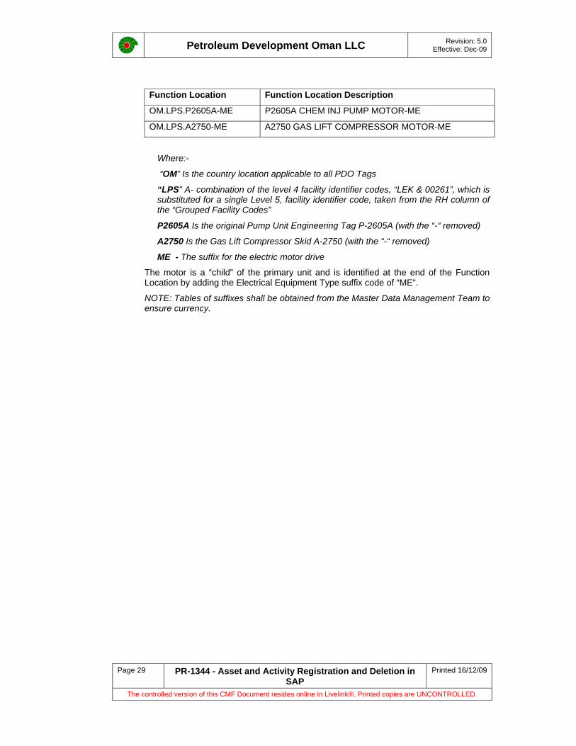
7.3 Functional Location Level 5 This is the next level down in the hierarchy, where specific equipment associated with the main equipment (Primary or Superior) is registered in SAP
In the previous example (Section 8.2) the Chemical Injection pump and the Gas Lift Compressor skid with the Tag formats P-2605A and A-2750 respectively, both have electric drive motors.
This equipment will be registered in SAP under P2605A and A2750 as the Primary Equipment; the hierarchy will be the Superior Function Location of the motors, as shown below.
Petroleum Development Oman LLC Revision: 5.0 Effective: Dec-09
Page 29 PR-1344 - Asset and Activity Registration and Deletion in SAP
Printed 16/12/09
The controlled version of this CMF Document resides online in Livelink®. Printed copies are UNCONTROLLED.
Function Location Function Location Description
OM.LPS.P2605A-ME P2605A CHEM INJ PUMP MOTOR-ME
OM.LPS.A2750-ME A2750 GAS LIFT COMPRESSOR MOTOR-ME
Where:-
“OM” Is the country location applicable to all PDO Tags
“LPS” A- combination of the level 4 facility identifier codes, “LEK & 00261”, which is substituted for a single Level 5, facility identifier code, taken from the RH column of the “Grouped Facility Codes”
P2605A Is the original Pump Unit Engineering Tag P-2605A (with the “-“ removed)
A2750 Is the Gas Lift Compressor Skid A-2750 (with the “-“ removed)
ME - The suffix for the electric motor drive
The motor is a “child” of the primary unit and is identified at the end of the Function Location by adding the Electrical Equipment Type suffix code of “ME”.
NOTE: Tables of suffixes shall be obtained from the Master Data Management Team to ensure currency.

Petroleum Development Oman LLC Revision: 5.0 Effective: Dec-09
Page 30 PR-1344 - Asset and Activity Registration and Deletion in SAP
Printed 16/12/09
The controlled version of this CMF Document resides online in Livelink®. Printed copies are UNCONTROLLED.
8 Standard Tag Format for Lifting Equipment
Refer to Appendix 1 for Code Identification Tables
8.1 Introduction\ Lifting equipment will include all types of Cranes (Static and Mobile), Lifting Beams, Lifting Appliances and Mechanical Handling Equipment (permanent or moveable). All lifting equipment has to be identified with a unique number and registered.
NOTE: This is a legal requirement under Lifting Operations and Lifting Equipment Regulations (LOLER)
8.1.1 Permanent Items
Functional Locations
Items such as overhead cranes, runway beams, chain block trolleys etc. that remain essentially in one location and that require regular inspection should be set up in SAP as functional locations. The naming convention for these is controlled by a standard that UOM apply to maintain consistency across PDO.
The Functional location contains a number of fields that contain information about the item such as object type, manufacturer, serial number etc.
Additional information is held in classification for the functional location e.g. is it an SCE? Where a functional location has equipment installed the details such as manufacturer etc will be held in the equipment record.
A workshop is also to be considered as a functional location.
Any removal, additions or changes to existing data in SAP will require a Z6 notification to be raised by the asset holder.
All items that require inspection / certification must have a maintenance plan to generate work orders for the preventive maintenance activities. The inspection frequencies shall be in accordance with PR-1708 - Lifting and Hoisting Procedure Inspection Testing and Certification Inspection.
Those items that are identified as Safety Critical, will have the additional integrity solution requirements to be satisfied i.e. results recording in SAP QM module.
Equipment Registered in SAP
Equipments in SAP have a unique number that is system generated in SAP. Where there is the potential for the item of equipment installed in the functional locations to be replaced (e.g. lifting appliances such as lever hoists, jacks etc in workshops) then an equipment record is also created and this would then be “installed” in the functional location in SAP. The maintenance of the equipment will be covered by the plan for the functional location that they are installed in.
8.1.2 Non-Permanent Items
Items such as slings, shackles etc are really considered to be consumable and these are not added to SAP, the administrative burden of keeping SAP up to date given the quick turnover of these items is not workable. At local level a Register needs to be maintained to keep track of these items. This is a legal requirement and therefore mandatory. The only thing that should be in SAP, is a preventative maintenance plan at the station level to test / inspect these items at the required interval, and the existing system of testing and colour coding etc, carries on as it is with the work order as the trigger for the activity.
Petroleum Development Oman LLC Revision: 5.0 Effective: Dec-09
Page 31 PR-1344 - Asset and Activity Registration and Deletion in SAP
Printed 16/12/09
The controlled version of this CMF Document resides online in Livelink®. Printed copies are UNCONTROLLED.
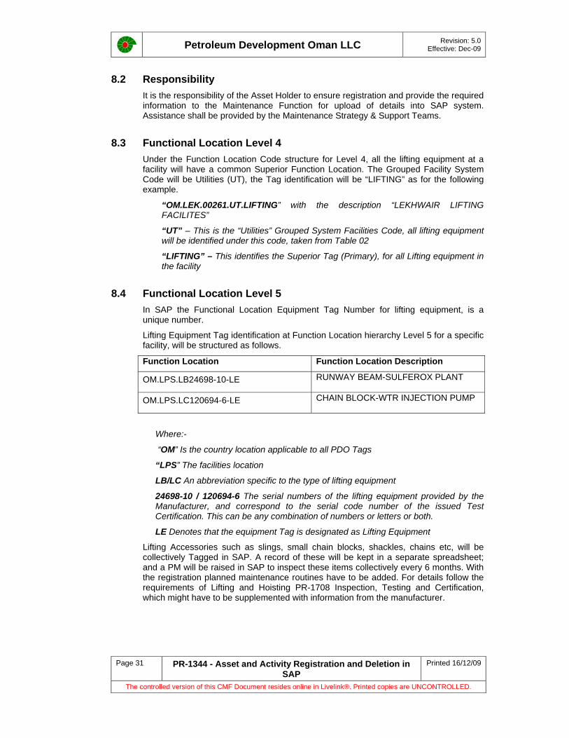
8.2 Responsibility It is the responsibility of the Asset Holder to ensure registration and provide the required information to the Maintenance Function for upload of details into SAP system. Assistance shall be provided by the Maintenance Strategy & Support Teams.
8.3 Functional Location Level 4 Under the Function Location Code structure for Level 4, all the lifting equipment at a facility will have a common Superior Function Location. The Grouped Facility System Code will be Utilities (UT), the Tag identification will be “LIFTING” as for the following example.
“OM.LEK.00261.UT.LIFTING” with the description “LEKHWAIR LIFTING FACILITES”
“UT” – This is the “Utilities” Grouped System Facilities Code, all lifting equipment will be identified under this code, taken from Table 02
“LIFTING” – This identifies the Superior Tag (Primary), for all Lifting equipment in the facility
8.4 Functional Location Level 5 In SAP the Functional Location Equipment Tag Number for lifting equipment, is a unique number.
Lifting Equipment Tag identification at Function Location hierarchy Level 5 for a specific facility, will be structured as follows.
Function Location Function Location Description
OM.LPS.LB24698-10-LE RUNWAY BEAM-SULFEROX PLANT
OM.LPS.LC120694-6-LE CHAIN BLOCK-WTR INJECTION PUMP
Where:-
“OM” Is the country location applicable to all PDO Tags
“LPS” The facilities location
LB/LC An abbreviation specific to the type of lifting equipment
24698-10 / 120694-6 The serial numbers of the lifting equipment provided by the Manufacturer, and correspond to the serial code number of the issued Test Certification. This can be any combination of numbers or letters or both.
LE Denotes that the equipment Tag is designated as Lifting Equipment
Lifting Accessories such as slings, small chain blocks, shackles, chains etc, will be collectively Tagged in SAP. A record of these will be kept in a separate spreadsheet; and a PM will be raised in SAP to inspect these items collectively every 6 months. With the registration planned maintenance routines have to be added. For details follow the requirements of Lifting and Hoisting PR-1708 Inspection, Testing and Certification, which might have to be supplemented with information from the manufacturer.

Petroleum Development Oman LLC Revision: 5.0 Effective: Dec-09
Page 32 PR-1344 - Asset and Activity Registration and Deletion in SAP
Printed 16/12/09
The controlled version of this CMF Document resides online in Livelink®. Printed copies are UNCONTROLLED.
9 Standard Tag Format for Control and Automation (Instruments)
Refer to Appendix 1 for Code Identification Tables
9.1 Introduction To address operation and maintenance requirements, SAP C&A Plant maintenance data is to be registered at SAP in a structured and consistent way across PDO. The information in this section has been extracted from a document produced by C&A Functional department (CDFP C&A), it provides the basic / minimum guidelines to achieve, good control and consistency on C&A data. This document has not been fully reviewed or approved and therefore cannot be quoted as a source.
The scope of the coverage includes instrumentation with executive action including:
• F&G devices,
• Pressure, Flow, Temperature and Vibration measurement, providing alarm or shutdown, and
• control and shutdown valves.
Indicating devices such as TI, FI, PI, PG, controllers, solenoid valves and limit switches are not to be included in SAP, only the measuring devices, the final elements, reset and trip switches are to be considered.
These SAP C&A Instrument Maintenance Management directives are to be followed while modifying and preparing new C&A Instrument Maintenance data.
9.1.1 Instrumented Protective Function Related Groups
Initiators (measuring devices)
Final Elements
9.1.2 Process Related Groups
Control Loops consisting off: -
• Primary Element - Transmitters
• Final Elements - Valves
Open Loops consisting off: -
• Primary Element - Transmitters
Station Flow meters
Computers
Analysers.
NOTES:
The SOV of an ESD valve is not required to be registered in SAP, if the ESD valve is registered the associated SOV’s are considered as part of the ESD valve.
The Pneumatic Pressure switch of a pneumatic Transmitter is not required to be registered in the SAP system if the Transmitters are registered. These switches are considered part of the transmitters.

Petroleum Development Oman LLC Revision: 5.0 Effective: Dec-09
Page 33 PR-1344 - Asset and Activity Registration and Deletion in SAP
Printed 16/12/09
The controlled version of this CMF Document resides online in Livelink®. Printed copies are UNCONTROLLED.
Pressure gauges and in between loop elements like Controllers, Summarizing units, Function generators, Ratio unit, I/P converters and valve actuators, limit switches, etc are not required to be registered in the SAP system, as these items have a high MTBF with no specific PM requirements.
9.2 Functional Location Level 4a The Instrument tags are grouped / structured under Main or Primary Equipment.
The Superior Tag Function Location for the Instrument Equipment Tags is the Primary Equipment Tag, followed by the C&A grouped system code CS. All the Instruments associated with the Primary equipment at Level 5, will be listed under this Superior Function Location.
Superior Function Location (4a) Superior Function Location Description
OM.LEK.00261.CG.V2692-CS V2692 INSTRUMENT CONTROL TAGS
OM.LEK.00261.WI.P2604D-CS P2604D INSTRUMENT CONTROL TAGS
9.3 Functional Location Level 5 The data input sources for SAP Instrument function location are the PEFS, Trip and Alarm Drawings and Field Data collection.
Instrumented Protective Function, Process Indication and Control Instruments is required to be registered in SAP; in order to carry out maintenance schedules and record equipment history.
Examples of the Level 5 Structure
Superior Function Location (Level 4a)
Function Location (Level 5)
Function Location Description (Level 5)
OM.KEK.00261.WI.P2604E OM.LPS.26-FZA-015-PT 2604E Pressure Switch
From the above the function location format can be determined as follows: -
OM - The country code location, applicable to all PDO Tags
LPS – This is the Facility / Station location code.
26 – Facility unit number, this is the first two numbers of the primary equipment V2692
Followed by ‘-‘
FZA - This is the parameter measured & Instrument function taken from the PEFS e.g. LRCA, FIC, FRC, and FT etc. Where the letter “Z” is included, it identifies it as being a safety executive action device for alarm and shutdown.
Followed by ‘-‘
015 – This is the instrument serial number taken from the PEFS
Trip Functions - Include the trip function H, HH or L, LL after the serial number on instruments that are IPF “Z” Tags only
Followed by ‘-‘
PT - This is the Instrument Type / Object type identified from the PFS, include the correct suffix from Table 10 i.e. LT, PT, PSW, FT, FSW, CV, etc.

Petroleum Development Oman LLC Revision: 5.0 Effective: Dec-09
Page 34 PR-1344 - Asset and Activity Registration and Deletion in SAP
Printed 16/12/09
The controlled version of this CMF Document resides online in Livelink®. Printed copies are UNCONTROLLED.
9.4 Instruments Common to a Parent Tag Common Instruments / equipment belonging to 2 or 3 rotating equipment, are to be listed under first rotating equipment with a word ‘Comn.’ at end of the description.
Where two or more Tags are in the PEFS with same serial number: -
Example: - LRCA-402A, LRCA-402B or 11-LRCA-402C
Should be uploaded into SAP as: -
OM.LPS.11-LRCA-402A-LT,
OM.LPS.11-LRCA-402B-LT
OM.LPS.11-LRCA-402C-LT
Or
OM.LPS.11-LRCA-402-1-LT,
OM.LPS.11-LRCA-402-2-LT
OM.LPS.11-LRCA-402-3-LT
9.5 Additional Fields and Class & Characteristic The two additional function location fields and relevant/applicable Class & Characteristic information below for each C&A Function Location are required to be collected/uploaded at SAP.
9.5.1 Additional functional location fields
Manufacture
Model
9.5.2 Class & Characteristic
EP_F_INST_UOM
EP_F_INST_Transmitter/Instrument - Range Lower value
EP_F_INST_Transmitter/Instrument -Range High value
EP_F_INST_Trip Low value
EP_F_INST_Trip High value
EP_F_INST_Alarm Low value
EP_F_INST_Alarm High Value
EP_F_INST_Maintenance Group
EP_F_INST_Application
EP_F_INST_SIL Level
EP_F_INST_Parameter of Measurement
EP_F_INST_Technical Object RRM Indicator
EP_F_GENERAL_P.E.F.S Drawing No
EP_F_Valve_Valve Cv Value
EP_F_Valve_Valve Size

Petroleum Development Oman LLC Revision: 5.0 Effective: Dec-09
Page 35 PR-1344 - Asset and Activity Registration and Deletion in SAP
Printed 16/12/09
The controlled version of this CMF Document resides online in Livelink®. Printed copies are UNCONTROLLED.
‘Application’ Characteristic values are used to indicate ‘Off Plot’ & ‘On Plot’ and ‘IPF’ & ‘Process control’ applications.
‘Parameter of Measurement’ Characteristic values are used to indicate the parameter measured/controlled.
‘Technical Object RRM Indicator’ Characteristic values are used to indicate the maintenance strategy.
‘Maintenance Group’ Characteristic values are used to indicate the Preventive maintenance groups.
Function location ‘ABC indicator’ field values have to be generated based on ‘EP_F_INST_Maintenance Group’ Characteristic values.
NOTE: EP 2009-9009 Safety Critical Element Management) should be consulted in the implementation of ABC Indicators and subsequent SCE Barriers.
The table below provides sample values to generate Class & Characteristic values Application Parameter of Measurement RRM Indicator Maintenance Group ABC Indicator
Instru.Protect.Funt. – Off Plot Analyser
IPF-Instrument Protective Function ANALYSER
B
Instru.Protect.Funt. – On Plot BSW
RCM-Reliability Centred Maintenance BS&W Meters
C
Process Indi.Ctrl – Off Plot Communicate
OFM- On Failure Maintenance ESD VALVES
A
Process Indi.Ctrl – On Plot Density FLOW METERS
C
ESDV-FE HEATER B
FE-Fin.Ele. IPF SAF GRD A
Fire IPF-FG A
Flow MFM A
Flow-FE MOL METERS A
Gas OFM Blank
Heat PROCES CRTL B
Level ROT.EQ.PAKGE B
Level-FE SYSTEMS A
No Parameter WELLHEAD MON C
Pressure
Pressure-FE
Smoke
Speed
Temperat-FE
Temperature
Vibration
Vibration-FE

Petroleum Development Oman LLC Revision: 5.0 Effective: Dec-09
Page 36 PR-1344 - Asset and Activity Registration and Deletion in SAP
Printed 16/12/09
The controlled version of this CMF Document resides online in Livelink®. Printed copies are UNCONTROLLED.
10 Standard Tag Format for Electrical Equipment
Refer to Appendix 1 for Code Identification Tables
10.1 Introduction The Function Location Source information is normally gathered from the project drawings and other source documents.
For the electrical facilities Function Location / Tagging i.e. TX, GEN, SW, CB, IS etc is generated from electrical drawings such as, Lighting & Small Power, Distribution Line drawings etc and will be guided by the Electrical CDFP as required.
The electrical equipment will include hardware such as lighting, both Emergency and normal, floodlights, main switchboard bus bar sections, switchgear, battery chargers, “Ex” junction boxes, distribution boards, electric motors, transformers, control panels, isolators, cathodic protection, overhead lines, electrical generators, circuit breakers.
From these electrical drawings the equipment is identified by the electrical legend, a SAP suffix is attributed to the equipment depending upon its function. The area code is then added, while the function of the equipment is taken from the drawings and included in the Function Location description.
At this point no serial number is added, the Tag is forwarded to the SAP Master Data Management Team who will allocate the Tag numbers.
10.2 Electrical Functional Location Level 3 The electrical systems will be grouped under an electrical system suffix code such as “ED” for Electrical Distribution, within a facility or station. Depending upon the function of the equipment, the Grouped Facility System suffix Code will be selected.
Superior Function Location Superior Function Location Description
OM.LEK.00261.ED. LEKHWAIR PROD STATION ELECTRICAL DIST
Where:-
“OM” Is the Country Location applicable to all PDO Tags
“LEK” Is the AREA abbreviated code, taken from the LH column in Table 01.
“00261” Is the Facility / Station numerical code
“ED” – From Electrical Grouped Facility System suffix codes
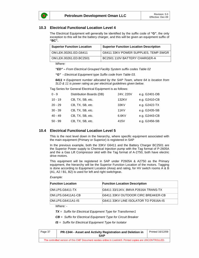
Petroleum Development Oman LLC Revision: 5.0 Effective: Dec-09
Page 37 PR-1344 - Asset and Activity Registration and Deletion in SAP
Printed 16/12/09
The controlled version of this CMF Document resides online in Livelink®. Printed copies are UNCONTROLLED.
10.3 Electrical Functional Location Level 4 The Electrical Equipment will generally be identified by the suffix code of “G”, the only exception to this will be the battery charger, and this will be given an equipment suffix of “BC”.
Superior Function Location Superior Function Location Description
OM.LEK.00261.ED.G6411 G6411 33KV POWER SUPPLIES, TEMP.SWGR
OM.LEK.00261.ED.BC2501 BC2501 110V BATTERY CHARGER-A
Where:
“ED” – From Electrical Grouped Facility System suffix codes Table 02
“G” - Electrical Equipment type Suffix code from Table 03.
6411 = Equipment number allocated by the SAP Team, where 64 is location from SLD & 11 is power rating as per electrical guidelines given below.
Tag Series for General Electrical Equipment is as follows:
0 - 9 Distribution Boards (DB) 24V, 220V e.g. G2401-DB
10 - 19 CB, TX, SB, etc. 132KV e.g. G2410-CB
20 - 29 CB, TX, SB, etc. 33KV e.g. G2422-TX
30 - 39 CB, TX, SB, etc. 11KV e.g. G2435-SB
40 - 49 CB, TX, SB, etc. 6.6KV e.g. G2443-CB
50 - 99 CB, TX, SB, etc. 415V e.g. G2456-SB
10.4 Electrical Functional Location Level 5 This is the next level down in the hierarchy, where specific equipment associated with the main equipment (Primary or Superior) is registered in SAP
In the previous example, both the 33KV G6411 and the Battery Charger BC2501 are the Superior Power supply to Chemical Injection pump with the Tag format of P-2605A and the a Gas Lift Compressor skid with the Tag format of A-2750, both have electric drive motors.
This equipment will be registered in SAP under P2605A & A2750 as the Primary equipment, the hierarchy will be the Superior Function Location of the motors. Tagging is done according to Equipment Location (Area) and rating, for HV switch rooms A & B (A1, A2 / B1, B2) is used for left and right switchgear.
Example:
Function Location Function Location Description
OM.LPS.G6411-TX G6411 33/11KV, 8MVA P2616A TRANS-TX
OM.LPS.G6411A1-CB G6411 33KV OUTDOOR CIRC BREAKER-CB
OM.LPS.G6411A1-IS G6411 33KV LINE ISOLATOR TO P2616A-IS
Where: -
TX = Suffix for Electrical Equipment Type for Transformer1
CB = Suffix for Electrical Equipment Type for Circuit Breaker
IS = Suffix for Electrical Equipment Type for Isolator
Petroleum Development Oman LLC Revision: 5.0 Effective: Dec-09
Page 38 PR-1344 - Asset and Activity Registration and Deletion in SAP
Printed 16/12/09
The controlled version of this CMF Document resides online in Livelink®. Printed copies are UNCONTROLLED.
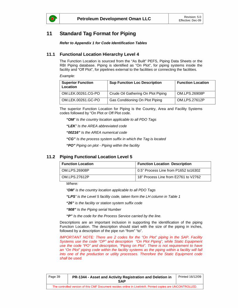
Petroleum Development Oman LLC Revision: 5.0 Effective: Dec-09
Page 39 PR-1344 - Asset and Activity Registration and Deletion in SAP
Printed 16/12/09
The controlled version of this CMF Document resides online in Livelink®. Printed copies are UNCONTROLLED.
11 Standard Tag Format for Piping
Refer to Appendix 1 for Code Identification Tables
11.1 Functional Location Hierarchy Level 4 The Function Location is sourced from the “As Built” PEFS, Piping Data Sheets or the RBI Piping database. Piping is identified as “On Plot”, for piping systems inside the facility and “Off Plot”, for pipelines external to the facilities or connecting the facilities.
Example:
Superior Function Location
Sup Function Loc Description Function Location
OM.LEK.00261.CG-PO Crude Oil Gathering On Plot Piping OM.LPS.26908P
OM.LEK.00261.GC-PO Gas Conditioning On Plot Piping OM.LPS.27612P
The superior Function Location for Piping is the Country, Area and Facility Systems codes followed by “On Plot or Off Plot code.
“OM” Is the country location applicable to all PDO Tags
“LEK” Is the AREA abbreviated code
“00216” Is the AREA numerical code
“CG” Is the process system suffix in which the Tag is located
“PO” Piping on plot - Piping within the facility
11.2 Piping Functional Location Level 5 Function Location Function Location Description
OM.LPS.26908P 0.5” Process Line from P1652 to16302
OM.LPS.27612P 18” Process Line from E2761 to V2762
Where:
“OM” is the country location applicable to all PDO Tags
“LPS” is the Level 5 facility code, taken form the LH column in Table 1
“26” is the facility or station system suffix code
“908” Is the Piping serial Number
“P” Is the code for the Process Service carried by the line.
Descriptions are an important inclusion in supporting the identification of the piping Function Location. The description should start with the size of the piping in inches, followed by a description of the pipe run “from” “to”.
IMPORTANT NOTE: There are 2 codes for the “On Plot” piping in the SAP. Facility Systems use the code “OP” and description “On Plot Piping”, while Static Equipment use the code “PO” and description, “Piping on Plot”. There is not requirement to have an “On Plot” piping code within the facility systems as the piping within a facility will fall into one of the production or utility processes. Therefore the Static Equipment code shall be used.

Petroleum Development Oman LLC Revision: 5.0 Effective: Dec-09
Page 40 PR-1344 - Asset and Activity Registration and Deletion in SAP
Printed 16/12/09
The controlled version of this CMF Document resides online in Livelink®. Printed copies are UNCONTROLLED.
12 Standard Tag Format for Fire and Safety Systems
Refer to Appendix 1 for Code Identification Tables
12.1 Functional Location Hierarchy Level 3 Fire Fighting and Safety Systems will be under the Grouped Facility System suffix code, “FF”.
Superior Function Location Sup Function Loc Description
OM.LEK.00261.FF Lekhwair Fire & Safety Components
12.2 Functional Location Hierarchy Level 4 The equipment code will identify the specific type of equipment to be found under Function Location Level 4.
Example:
Superior Function Location Sup Function Loc Description
OM.LEK.00261.FF-FE Lekhwair Pump Stn Fire Extinguishers
OM.LEK.00261.FF-FH Lekhwair Pump Stn Fire Hydrants
OM.LEK.00261.FF-SS Lekhwair Pump Stn Safety Showers
Where:
“FF-FE” = Fire Extinguishers
“FF-FH” = Fire Hydrants
“FF-SS” = Safety Showers
12.3 Functional Location Hierarchy Level 5 The Function Location will combine the area codes followed by the Tag number given to the specific location for the equipment, followed by the suffix code of the equipment.
Example:
Function Location Function Loc Description
OM.LPS.CL-0043-FE FIRE EXT.CO2 4.55KG TELECOM BLDING-FE
OM.LPS.BATL-004-BA BA SET TROLLEY FIRE STATION CLASSROOM-BA
OM.LCP.DL-0133-FE FIRE EXT.DCP 12KG PROD CHEM LAB-FE

Petroleum Development Oman LLC Revision: 5.0 Effective: Dec-09
Page 41 PR-1344 - Asset and Activity Registration and Deletion in SAP
Printed 16/12/09
The controlled version of this CMF Document resides online in Livelink®. Printed copies are UNCONTROLLED.
13 Telecommunications Equipment
Telecommunications Equipment will include the Public Announcement system which can comprise base stations / speakers, radio base stations / portable radios, telephones and “Ex” equipment associated with telecommunications hardware.
As there is no Facility System suffix identified for telecommunications equipment, this section will have to be reviewed and completed at a later date.
Petroleum Development Oman LLC Revision: 5.0 Effective: Dec-09
Page 42 PR-1344 - Asset and Activity Registration and Deletion in SAP
Printed 16/12/09
The controlled version of this CMF Document resides online in Livelink®. Printed copies are UNCONTROLLED.
14 Functional Location Non Compliance
Where the format of the Function Location data entries into SAP deviate from the above guidelines, for whatever reason, a waiver will be required to be presented to SAP Master Data Management Team with an approved justification.
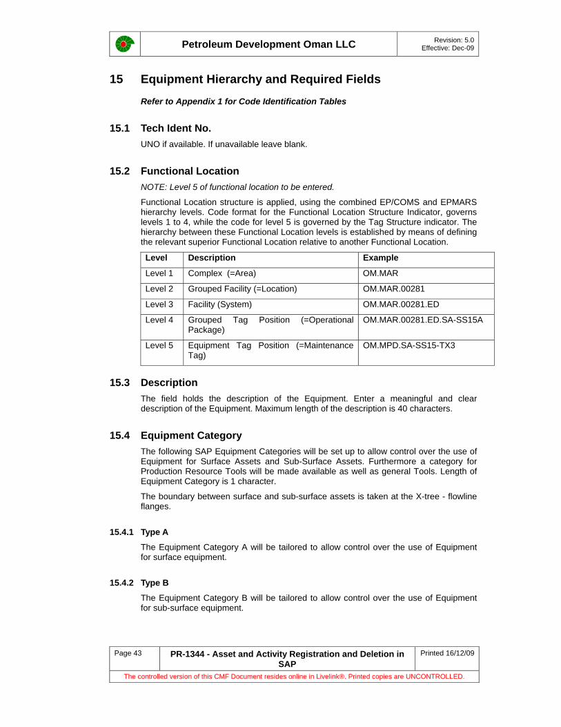
Petroleum Development Oman LLC Revision: 5.0 Effective: Dec-09
Page 43 PR-1344 - Asset and Activity Registration and Deletion in SAP
Printed 16/12/09
The controlled version of this CMF Document resides online in Livelink®. Printed copies are UNCONTROLLED.
15 Equipment Hierarchy and Required Fields
Refer to Appendix 1 for Code Identification Tables
15.1 Tech Ident No. UNO if available. If unavailable leave blank.
15.2 Functional Location NOTE: Level 5 of functional location to be entered.
Functional Location structure is applied, using the combined EP/COMS and EPMARS hierarchy levels. Code format for the Functional Location Structure Indicator, governs levels 1 to 4, while the code for level 5 is governed by the Tag Structure indicator. The hierarchy between these Functional Location levels is established by means of defining the relevant superior Functional Location relative to another Functional Location.
Level Description Example
Level 1 Complex (=Area) OM.MAR
Level 2 Grouped Facility (=Location) OM.MAR.00281
Level 3 Facility (System) OM.MAR.00281.ED
Level 4 Grouped Tag Position (=Operational Package)
OM.MAR.00281.ED.SA-SS15A
Level 5 Equipment Tag Position (=Maintenance Tag)
OM.MPD.SA-SS15-TX3
15.3 Description The field holds the description of the Equipment. Enter a meaningful and clear description of the Equipment. Maximum length of the description is 40 characters.
15.4 Equipment Category The following SAP Equipment Categories will be set up to allow control over the use of Equipment for Surface Assets and Sub-Surface Assets. Furthermore a category for Production Resource Tools will be made available as well as general Tools. Length of Equipment Category is 1 character.
The boundary between surface and sub-surface assets is taken at the X-tree - flowline flanges.
15.4.1 Type A
The Equipment Category A will be tailored to allow control over the use of Equipment for surface equipment.
15.4.2 Type B
The Equipment Category B will be tailored to allow control over the use of Equipment for sub-surface equipment.

Petroleum Development Oman LLC Revision: 5.0 Effective: Dec-09
Page 44 PR-1344 - Asset and Activity Registration and Deletion in SAP
Printed 16/12/09
The controlled version of this CMF Document resides online in Livelink®. Printed copies are UNCONTROLLED.
15.4.3 Type P
The Equipment Category P will be tailored to allow control over the use of Equipment as Production Resource Tool (PRT) objects.
NOTE: PRT Equipment permit the existence of a technical object on which maintenance is performed, but which is also required to serve as a tool for the maintenance of other technical objects. To distinguish between regular Equipment and PRTs, a special category has been created: Production Resources Tools.
The legacy systems do not appear to hold any data related to PRTs. The category will be available for the business if they decide to use it.
15.4.4 Type Q
The Equipment Category Q will be tailored to allow control over the use of Equipment as Tool objects.
15.5 Object Type The Object Type can both cover Functional Locations as well as Equipment in one single pull down menu. This could potentially be confusing. For PDO, assignment of Object Types to Equipment only has been decided as this is seen as to be more useful. Users are likely to want to search for Equipment of a Specific Type, like Pump-Centrifugal or Vessel-Separation, etc. Maximum length of Object Type is 10 characters.
A consolidated list of Object Types for all PDO assets, thus not only ex-EPMARS (surface facilities), but also estate, telecom, IT, wells, automation & control Equipment Object Types.
For the facilities ISO 14224 and the Steplib convention could serve as the reference, using the ISO 14224 Class and Type combination much like NAM did.
A centrifugal pump would then be Object Type PUCE (Class Pump = PU, while Type Centrifugal = CE), etc.
15.6 Weight In this field the Weight can be entered. The weight of that Equipment can be used for load calculations, lifting and transportation purposes. Maximum length of the Weight is 17 characters.
15.7 Unit of Weight The Units of weight can be selected using the pull down menu. The following standard units are available: Gram, Kilogram, US Pound, Milligram, Ounce, Tonnes, US Ton. For PDO we will use the Standard Units of measure. Maximum length of the Weight Unit is 3 characters. KG : Kilogram.
15.8 Size/Dimension In this field the Size/Dimension can be entered. The Size/Dimension of that Equipment can be used for lifting and transportation purposes. There is no firm format for dimensions available in SAP. But the following formats could be used as a standard. Maximum length of the Size/dimension is 18 characters.
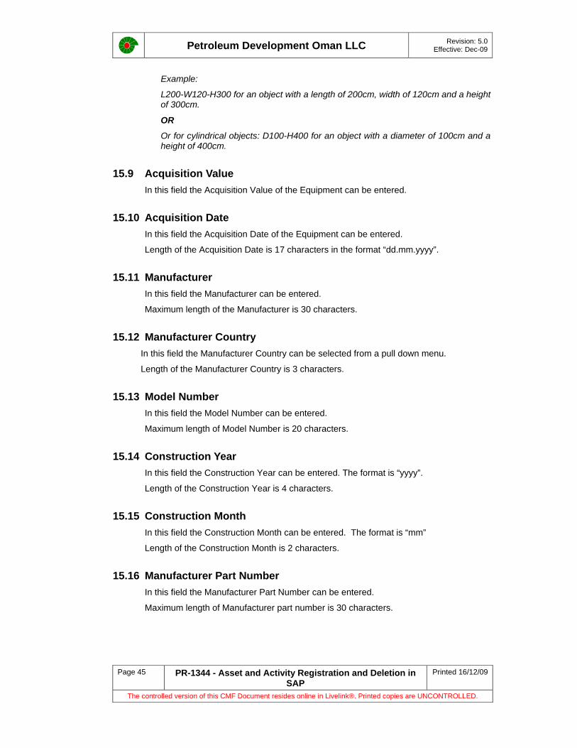
Petroleum Development Oman LLC Revision: 5.0 Effective: Dec-09
Page 45 PR-1344 - Asset and Activity Registration and Deletion in SAP
Printed 16/12/09
The controlled version of this CMF Document resides online in Livelink®. Printed copies are UNCONTROLLED.
Example:
L200-W120-H300 for an object with a length of 200cm, width of 120cm and a height of 300cm.
OR
Or for cylindrical objects: D100-H400 for an object with a diameter of 100cm and a height of 400cm.
15.9 Acquisition Value In this field the Acquisition Value of the Equipment can be entered.
15.10 Acquisition Date In this field the Acquisition Date of the Equipment can be entered.
Length of the Acquisition Date is 17 characters in the format “dd.mm.yyyy”.
15.11 Manufacturer In this field the Manufacturer can be entered.
Maximum length of the Manufacturer is 30 characters.
15.12 Manufacturer Country In this field the Manufacturer Country can be selected from a pull down menu.
Length of the Manufacturer Country is 3 characters.
15.13 Model Number In this field the Model Number can be entered.
Maximum length of Model Number is 20 characters.
15.14 Construction Year In this field the Construction Year can be entered. The format is “yyyy”.
Length of the Construction Year is 4 characters.
15.15 Construction Month In this field the Construction Month can be entered. The format is “mm”
Length of the Construction Month is 2 characters.
15.16 Manufacturer Part Number In this field the Manufacturer Part Number can be entered.
Maximum length of Manufacturer part number is 30 characters.

Petroleum Development Oman LLC Revision: 5.0 Effective: Dec-09
Page 46 PR-1344 - Asset and Activity Registration and Deletion in SAP
Printed 16/12/09
The controlled version of this CMF Document resides online in Livelink®. Printed copies are UNCONTROLLED.
15.17 Manufacturer Serial Number In this field the Manufacturer Serial Number can be entered.
Maximum length of the Manufacturer Serial Number is 30 characters.
15.18 Authorization Group Defines the Authorization Group to create and change Equipment. It is expected that only a small group of people will create and change Equipment. Equipment data by nature is rather static. In practice dedicated groups of people will create and maintain Equipment Records in their expertise area. It is required to fence off Equipment data that are in the domain of another Authorization Group. Below the Authorization Groups are given.
Maximum length of the Authorization Group is 4 Characters.
An example of possible Authorization Groups (needs to be established during Role Mapping):
• OM10: Surface Assets (hydro-carbon producing)
• OM20: Sub-Surface Assets (hydro-carbon producing)
• OM30: Estate Assets
• OM40: Telecom Assets
• OM50: IT Assets
15.19 Start-up Date In this field the Start-up Date (Commission-Date) of the Equipment can be entered.
The format is “dd.mm.yyyy”
The length of the Start-up Date is 8 characters.
15.20 Maintenance Plant In this field the Maintenance Plant is entered. For PDO there will be only one Work Management Maintenance Plant, namely OM01. See PR-1032 – Maintenance Plan Creation and Approval Procedure.
15.21 Company Code The PDO Company code will be OM01. The Company Code will be defaulted in when OM01 has been entered in the field Maintenance Plant on the Location Tab.
15.22 Asset The asset field permits a straight link with the FI Asset Accounting (Asset Register). In this field the Asset code can be entered to link the FN Asset Register with the PM Equipment. DSM/FN has decided not to populate this field during data load, but will enter the relevant codes after go-live. The length of the Asset is 12 characters.
Petroleum Development Oman LLC Revision: 5.0 Effective: Dec-09
Page 47 PR-1344 - Asset and Activity Registration and Deletion in SAP
Printed 16/12/09
The controlled version of this CMF Document resides online in Livelink®. Printed copies are UNCONTROLLED.
15.23 Sub-number The sub-asset field permits a straight link with the FI Asset Accounting (Asset Register). In this field the Sub-Asset code will be entered to link the FN Asset Register with the PM Equipment. DSM/FN has decided not to populate this field during data load, but will enter the relevant codes after go-live. The length of Sub-number is 4 characters.
15.24 Catalogue Profile This field could hold a Catalog Profile, applicable for a Technical Object. This field can be populated with a so-called Object Part code. Depending on the Object Part (Pump-Centrifugal, Pump-Reciprocating, etc.) there will be a different Damage code and Damage Cause code specific to a certain Object Part.
The Catalog Profile field will be used in the Equipment record to link the Object Part code. This link will ease completion of PM Notifications raised on Equipment, as the link to the Object Part code will direct the selection of an appropriate Damage code and Damage Cause code.
The length of the Catalog Profile is 9 characters.

Petroleum Development Oman LLC Revision: 5.0 Effective: Dec-09
Page 48 PR-1344 - Asset and Activity Registration and Deletion in SAP
Printed 16/12/09
The controlled version of this CMF Document resides online in Livelink®. Printed copies are UNCONTROLLED.
16 Class_FLOC Required Fields
Refer to Appendix 1 for Code Identification Tables
16.1 Class Type A class type is a top-level unit of control for classes. Each class must be allocated to exactly one class type. There is no connection between the individual class types.
Class Type 003 stands for Functional Location.
16.2 TechIdentNo. Level 5 of Functional Location.
Level 5 Equipment Tag Position (=Maintenance Tag) OM.MPD.SA-SS15-TX10
16.3 Class F_GENERAL is used for General Functional Location class.
16.4 Characteristic An attribute related to a Class. A class may have more than one characteristic.
Following are the characteristics for F_GENERAL:-
FL001 LAST VERIFICATION DATE
FL002 FLUID HANDLED
FL003 EDCC - ENGINEERING DESIGN CODE
FL004 STREAM 1
FL005 STREAM 2
FL006 STREAM 3
FL007 STREAM 4
FL008 STREAM 5
16.5 Int.Meas.Unit Unit in which a numeric characteristic value is entered.
FL006 STREAM 3
FL007 STREAM 4
FL008 STREAM 5
Petroleum Development Oman LLC Revision: 5.0 Effective: Dec-09
Page 49 PR-1344 - Asset and Activity Registration and Deletion in SAP
Printed 16/12/09
The controlled version of this CMF Document resides online in Livelink®. Printed copies are UNCONTROLLED.
17 Class_Equi Required Fields
Refer to Appendix 1 for Code Identification Tables
17.1 Class Type Uniquely identifies the class type. A class type is a top-level unit of control for classes. Each class must be allocated to exactly one class type. There is no connection between the individual class types. Class Type 002 stands for Equipment class.
17.2 TechIdentNo. Equipment Number can be entered here. E.g. 30000000157
17.3 Class Class VASB stands for Valve - PSV conventional with bellows. This is used for Relief valves without bellows.
17.4 Characteristic An attribute related to a Class. A class may have more than one characteristic. E.g. EP249 - Inlet size, EP7108 – Set Pressure Positive etc. For complete characteristic refer to Data Loading Form.
Char. Value
Value of the characteristics.
Int.meas.unit
Unit in which a numeric characteristic value is entered.

Petroleum Development Oman LLC Revision: 5.0 Effective: Dec-09
Page 50 PR-1344 - Asset and Activity Registration and Deletion in SAP
Printed 16/12/09
The controlled version of this CMF Document resides online in Livelink®. Printed copies are UNCONTROLLED.
Appendix 1 – Code Identification Tables
The following Code Identification Tables should be used carefully for reference and / or example. The contents and currency of the information may change and may not be reflected in these forms. If there is uncertainty then the SAP Master Data Management Team shall be consulted.
Table 1
Grouped Facility (Station) Codes
Level 2 Grouped Facility Codes Grouped Facility Location Descriptions Level 5 Facility
Codes
OM.ALG.00101 Al Ghubar Prod Station and Field Fac GPS
OM.ALN.00106 Al Noor Interstation Pipelines ALP
OM.ALN.00107 Al Noor Prod Station and Field Fac APS
OM.ALN.99974 Items to be written off in Al Noor WOF
OM.ANZ.00108 ANZAUZ STATION AND FIELD FACILITY ZPS
OM.ANZ.00493 INTERFIELD PIPE LINES ZLP
OM.ANZ.99975 ITEMS TO BE WRITTEN OFF IN ANZAUZ WOF
OM.EXP.00101 Exploration Al Ghubar EXP
OM.EXP.99976 Items to be written off in Exploration WOF
OM.FAH.00217 Fahud SW Field Facilities FAS
OM.FAH.00218 Fahud Supply FSU
OM.GAS.00247 Barik Gas Gathering Station GGB
OM.GAS.00248 Power Plant Saih Rawl (CPP-IPS) GGE
OM.HWL.00710 Dafaq RMS and Field Facility DAF
OM.HWL.00711 Ghafeer RMS and Field Facility GFR
OM.LEK.00201 Dhulaima Field Facilities DHU
OM.LEK.00202 Malaan Field Facilities LPS
OM.LEK.99979 Items to be written off in Lekhwair WOF
OM.MAF.00277 Coastal Workshops TWS
OM.MAF.00278 Marine / Offshore TOF
OM.YIB.00523 Yibal C Station and Field Facilities YBC
OM.YIB.00524 Yibal Camp YCP
OM.YIB.00525 Yibal Camp Infrastructure YCI
OM.ZAL.00546 ZAULIYAH STATION AND FIELD FACILITY ZAS

Petroleum Development Oman LLC Revision: 5.0 Effective: Dec-09
Page 51 PR-1344 - Asset and Activity Registration and Deletion in SAP
Printed 16/12/09
The controlled version of this CMF Document resides online in Livelink®. Printed copies are UNCONTROLLED.
Table 2
Grouped Facility System Codes
System Codes System Description System Codes System Description
AR Area Roads IR In camp Residences
BS MAF Booster Station IS Irrigation System & Facilities
BV Block Valves Stations IW Instrumentation workshop
CA Control and Safeguarding LB Prod & Chem Lab Complex
CB Commercial Buildings LC Local Business Centre
CC Control Centre LD Learning & Development Complex
CD Crude Dehydration LG Gas Lift Wells
CE Crude Evacuation MP Mud Mixing Plant
CF Commercial Facility MS Mosques
CG Crude Gathering MW Mechanical workshop
CH Camp Horticulture OB Office Building
CI Chemical Injection OE Oil Exhibition Centre / Planetarium
CJ Computer Centre OP On Plot Piping
CL Clinic Building OR Off Camp Residences
CM Camp Maintenance Building OS Observation Wells
CN Catering OW Oil Wells
CO Community Aid Roads PL Main Pipeline
CP Compression Facilities PW Production workshop
CR Camp Roads PY PDO Yards
CS Crude stabilisation RC Recreation Buildings
CT Crude Transportation RE Recreational Centre
CW Campaign Workshop RO R.O. Plant
CY Contractor Yard RS RAH RC Swimming Pool
ED Elec. Distribution RV RV Workshops
EG Elec. Generation SC Study Centre
EL Exploration Laboratory SE Sewage Treatment Plant
ES Estate Services Compound SF Surface Facilities
ET Elec. transmission SG Safeguarding
EW Electrical Workshop SI Steam Injection
EX Exploration Wells SN Suspended Wells
F8 Main intake station ST Station Tags
FA Farm SU Supply Buildings
*FF Fire and Safety Compound SW SEEB Water Injection Wells
FG Fuel Gas TB Terminal Buildings Area
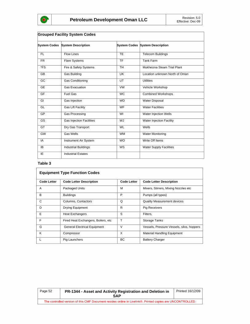
Petroleum Development Oman LLC Revision: 5.0 Effective: Dec-09
Page 52 PR-1344 - Asset and Activity Registration and Deletion in SAP
Printed 16/12/09
The controlled version of this CMF Document resides online in Livelink®. Printed copies are UNCONTROLLED.
Grouped Facility System Codes
System Codes System Description System Codes System Description
FL Flow Lines TE Telecom Buildings
FR Flare Systems TF Tank Farm
*FS Fire & Safety Systems TH Mukheizna Steam Trial Plant
GB Gas Building UK Location unknown North of Oman
GC Gas Conditioning UT Utilities
GE Gas Evacuation VW Vehicle Workshop
GF Fuel Gas WC Combined Workshops
GI Gas Injection WD Water Disposal
GL Gas Lift Facility WF Water Facilities
GP Gas Processing WI Water Injection Wells
GS Gas Injection Facilities WJ Water Injection Facility
GT Dry Gas Transport WL Wells
GW Gas Wells WM Water Monitoring
IA Instrument Air System WO Write Off Items
IB Industrial Buildings WS Water Supply Facilities
IE Industrial Estates
Table 3
Equipment Type Function Codes
Code Letter Code Letter Description Code Letter Code Letter Description
A Packaged Units M Mixers, Stirrers, Mixing Nozzles etc
B Buildings P Pumps (all types)
C Columns, Contactors Q Quality Measurement devices
D Drying Equipment R Pig Receivers
E Heat Exchangers S Filters,
F Fired Heat Exchangers, Boilers, etc T Storage Tanks
G General Electrical Equipment V Vessels, Pressure Vessels, silos, hoppers
K Compressor X Material Handling Equipment
L Pig Launchers BC Battery Charger
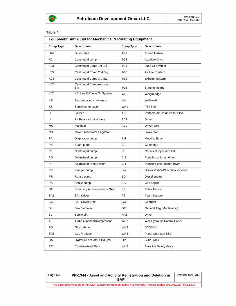
Petroleum Development Oman LLC Revision: 5.0 Effective: Dec-09
Page 53 PR-1344 - Asset and Activity Registration and Deletion in SAP
Printed 16/12/09
The controlled version of this CMF Document resides online in Livelink®. Printed copies are UNCONTROLLED.
Table 4
Equipment Suffix List for Mechanical & Rotating Equipment
Equip Type Description Equip Type Description
HA2 Driven Unit TG2 Power Turbine
KC Centrifugal comp TG3 Auxiliary Drive
KC1 Centrifugal Comp 1st Stg TG4 Lube Oil System
KC2 Centrifugal Comp 2nd Stg TG5 Air Inlet System
KC3 Centrifugal Comp 3rd Stg TG6 Exhaust System
KC4 Centrifugal Compressor 4th Stg TG8 Starting Means
KC5 KC Seal Oil/Lube Oil System WB Weighbridge
KR Reciprocating compressor WH Wellhead
KS Screw compressor WH1 PTS line
LH Launch AC Portable Air Compressor Skid
LI Air Balance Unit (Liner) AC1 Driver
MG Manifold AC2 Driven Unit
MX Mixer / Macerator / Agitator BF Blower/fan
PA Diaphragm pump BM Mooring Buoy
PB Beam pump CF Centrifuge
PF Centrifugal pump CI Chemical Injection Skid
PG Gearwheel pump CI3 Pumping unit - air driven
PI Air Balance Unit (Piston) CI4 Pumping unit - motor driven
PP Plunger pump DW Drwwks/Der'k/Winch/Hoist/Boom
PR Rotary pump ED Diesel engine
PS Screw pump EG Gas engine
SA Breathing Air Compressor Skid EP Petrol Engine
SA1 SA - Driver FS Foam System
SA2 SA - Driven Unit GB Gearbox
SK Sea Skimmer GM General Tag (Mechanical)
SL Screw Lift HA1 Driver
TE Turbo expander/Compressor WH2 Well Hydraulic Control Panel
TG Gas turbine WH3 SCSSSV
TG1 Gas Producer WH4 Panel Operated SSV
HA Hydraulic Actuator Skid (M/L) OP BOP Stack
RO Containerised Plant WH5 Flow line Safety Valve

Petroleum Development Oman LLC Revision: 5.0 Effective: Dec-09
Page 54 PR-1344 - Asset and Activity Registration and Deletion in SAP
Printed 16/12/09
The controlled version of this CMF Document resides online in Livelink®. Printed copies are UNCONTROLLED.
Table 5
Equipment Suffix List for Static Equipment
Equip Type Description Equip
Type Description
AC6 Receiver IP Interfield Pipelines
AR Aerator OB Office Buildings
BR Flare LA Loading arm
BV Block Valve LE Lifting equipment
CI1 Storage tank LS Scraper launcher
CI2 Day Tank OT Oil Treatment Unit
CO Column / Tower / Contactor PD Pulsation damper
DG Gas scrubber PO Piping - On plot
DR Dryer RA Air receiver
FA Flame Arrestor RS Scraper receiver
FL Filter RV Relief valve
FN Gas/Oil/Water Flow lines SA3 SA - Accumulator
FU Furnace/heater SR Separator
GS Steam generator TK Tank
HD Header TP Tank Pit
HE Heat exchanger VE Vessel
KO Knock out vessel WS Water softener
IB Industrial Buildings
Table 6
Cranes CODE TYPE DESCRIPTION CODE TYPE DESCRIPTION
CPJ Crane Pedestal Jib CTL Crane Truck Loading
CFPJ Crane Free Standing CART Crane Articulating
CPOJ Crane Portable Jib CSBP Crane Side Boom Pipelayers
CPSJ Crane Pillar Swing CPOT Crane Powered Overhead Travelling
CWSJ Crane Wall Mounted Swing Jib CMOT Crane Manual Overhead Travelling
CCA Crane Cantilever CMOTS Crane Manual Overhead Travelling Structure
CFG Crane Fixed Gantry CTL Crane Truck Loading
CPG Crane Portable Gantry CART Crane Articulating
CCL Crane Crawler Mounted Lattice CSBP Crane Side Boom Pipe layers
CCT Crane Crawler Mounted Telescopic CPOT Crane Powered Overhead
Travelling
CCML Crane Carrier Mounted Lattice CMOT Crane Manual Overhead Travelling
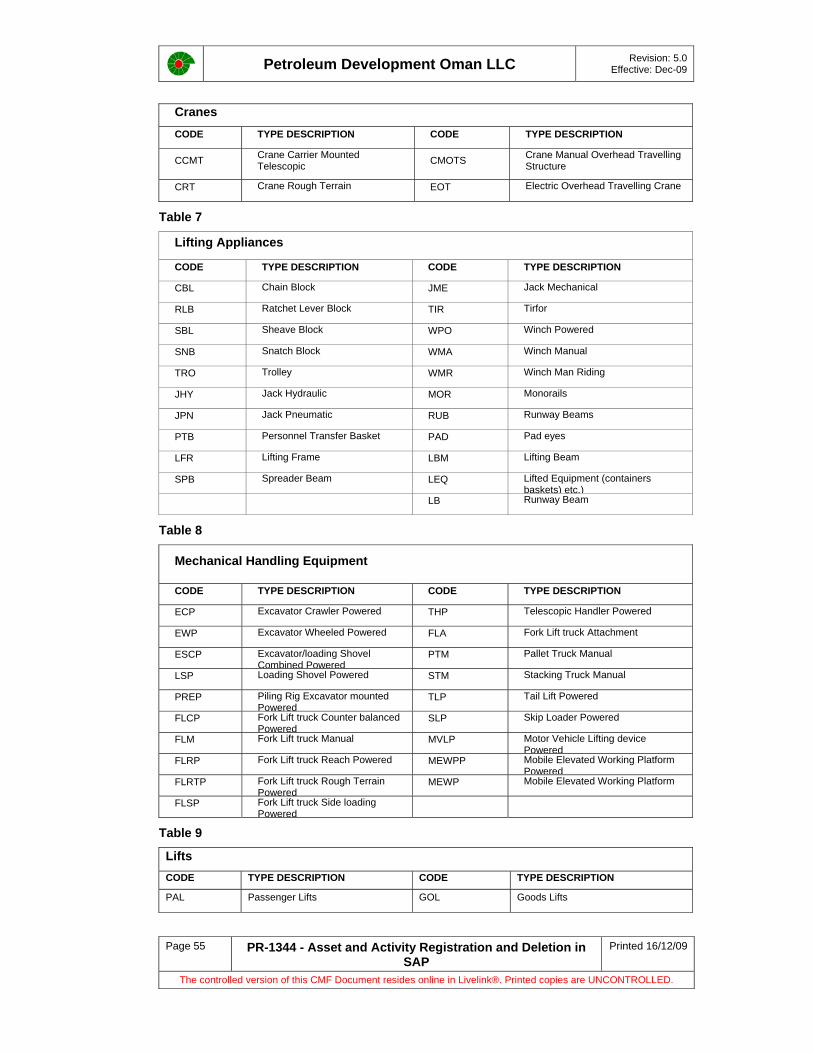
Petroleum Development Oman LLC Revision: 5.0 Effective: Dec-09
Page 55 PR-1344 - Asset and Activity Registration and Deletion in SAP
Printed 16/12/09
The controlled version of this CMF Document resides online in Livelink®. Printed copies are UNCONTROLLED.
Cranes CODE TYPE DESCRIPTION CODE TYPE DESCRIPTION
CCMT Crane Carrier Mounted Telescopic CMOTS Crane Manual Overhead Travelling
Structure
CRT Crane Rough Terrain EOT Electric Overhead Travelling Crane
Table 7
Lifting Appliances
CODE TYPE DESCRIPTION CODE TYPE DESCRIPTION
CBL Chain Block JME Jack Mechanical
RLB Ratchet Lever Block TIR Tirfor
SBL Sheave Block WPO Winch Powered
SNB Snatch Block WMA Winch Manual
TRO Trolley WMR Winch Man Riding
JHY Jack Hydraulic MOR Monorails
JPN Jack Pneumatic RUB Runway Beams
PTB Personnel Transfer Basket PAD Pad eyes
LFR Lifting Frame LBM Lifting Beam
SPB Spreader Beam LEQ Lifted Equipment (containers baskets) etc.)
LB Runway Beam
Table 8
Mechanical Handling Equipment
CODE TYPE DESCRIPTION CODE TYPE DESCRIPTION
ECP Excavator Crawler Powered THP Telescopic Handler Powered
EWP Excavator Wheeled Powered FLA Fork Lift truck Attachment
ESCP Excavator/loading Shovel Combined Powered
PTM Pallet Truck Manual
LSP Loading Shovel Powered STM Stacking Truck Manual
PREP Piling Rig Excavator mounted Powered
TLP Tail Lift Powered
FLCP Fork Lift truck Counter balanced Powered
SLP Skip Loader Powered
FLM Fork Lift truck Manual MVLP Motor Vehicle Lifting device Powered
FLRP Fork Lift truck Reach Powered MEWPP Mobile Elevated Working Platform Powered
FLRTP Fork Lift truck Rough Terrain Powered
MEWP Mobile Elevated Working Platform
FLSP Fork Lift truck Side loading Powered
Table 9
Lifts CODE TYPE DESCRIPTION CODE TYPE DESCRIPTION
PAL Passenger Lifts GOL Goods Lifts

Petroleum Development Oman LLC Revision: 5.0 Effective: Dec-09
Page 56 PR-1344 - Asset and Activity Registration and Deletion in SAP
Printed 16/12/09
The controlled version of this CMF Document resides online in Livelink®. Printed copies are UNCONTROLLED.
Table 10
Instrument Equipment Type Suffix
Type Description Type Description
ACT Actuator MP Metering prover
ANP Analyzer Probe MV Multi port selector valve
AP Accelerometer Probe OC Net oil computer
AQ Analyser ORI Orifice
BGU Break Glass unit PAN Panel
ADT Acoustic Detector PBT Push button
BOX Box PDM Positive Displacement Meter
BSW BSW meter PLC PLC
CAB Cabinet PP Proximity Probe
CC Control Centre PSF Process sensor Flow
CCR Central control room PSL Process sensor Level
COMP Computer PSP Process sensor Pressure
CON Controller PST Process sensor Temperature
COR Corriolis flow meter PSW Pressure switch
CS Control System PT Pressure Transmitter
CV Control valve PX Horn/Loud Speaker
DB Distribution Board PY Beacon
DCS DCS system QM Quality Monitor
DT Density Meter QMMP Quality Monitor Meter Prover
FDT Flame detector RC Rod Pump controller
FG Facility Equip/Fire & Gas REC Recorder
FLDT Flow Detector RL Relay
FPC Field PAC Controller RT RTU
FSW Flow switch SC Single Well Safety Cabinet
FT Flow transmitter SDT Smoke Detector
GAN General Analyzer SL Sonic Leak Gas Detector
GBS Limit Switch SOV Solenoid valve
GDT Gas detector SQ SCADA Equipment
GF Vessel SPD Speed related
GI General Instrument Tag SRV Self Regulating valve
HDT Heat detector SW Switch
JB Junction Box TR Transducer
LG Level Guage TSW Temperature switch
LP Logic Relay Panel TT Temperature Transmitter
LSW Level switch TUR Turbine Flow meter
LT Level Transmitter UDT UV detector
MAG Magnetic flow meter UT Ultrasonic Flow Transmitter
MAS Mass flow meter VA Valve

Petroleum Development Oman LLC Revision: 5.0 Effective: Dec-09
Page 57 PR-1344 - Asset and Activity Registration and Deletion in SAP
Printed 16/12/09
The controlled version of this CMF Document resides online in Livelink®. Printed copies are UNCONTROLLED.
Instrument Equipment Type Suffix
Type Description Type Description
MIS Misc. VI Vibration
MON Monitor VOR Vortex flow meter
MOV Motor Operated valve VSW Vibration switch
MR Metering XL Emergency Shutdown Valve (ESD)
OA Multiphase metering skid
OANA Oxygen Analyzer
Table 11
SAP Suffix for Electrical Equipment Type Equip Type
Description Equip Type
Description Equip Type
Description
PAN Panel Teleprotection ER Electrical Starting Reactor
RP Electrical protection
PQ Gas/Oil Main Pipelines ES Electrical System RP1 Motor Protector
EX Certified equipment GE Electric generator SB Switchboard
BS Bus section GL General Tag (Electrical) SP Solar Panel
CB Circuit breaker IS Isolator SQ SCADA Equipment
CC Control panel IW Package air conditioner TC Cathodic Prot Transformer
CI5 Pumping unit driver LU Lighting Unit TG7 Electrical System
CT Current transformer ME Electric motor TX Transformer
DB Distribution board OH Overhead lines VT Capacitor voltage transformer
EC ESP Control Panel PE Electric Submersible Pump
YD Switchyard
EQ Electrical Equipment JB Junction Box
Table 12
Table 12 Fire & Safety Components Suffix Codes CODE DESCRIPTION CODE DESCRIPTION
FE Fire Extinguisher FB Fire Box
FH Fire Hydrants SS Safety Shower
FM Fire Monitors BA Breathing Apparatus
SP Sprinkler System FT Fire Truck
DL Deluge
GS Gaseous Fire Protection
HR Hose Reels

Petroleum Development Oman LLC Revision: 5.0 Effective: Dec-09
Page 58 PR-1344 - Asset and Activity Registration and Deletion in SAP
Printed 16/12/09
The controlled version of this CMF Document resides online in Livelink®. Printed copies are UNCONTROLLED.
Appendix 2 - SAP Master Data Management Team Templates
The following Data Loading Templates should be used with the Section 2 of this procedure. If in doubt then consult the SAP Master Data Management Team for guidance.
Data Loading Templates
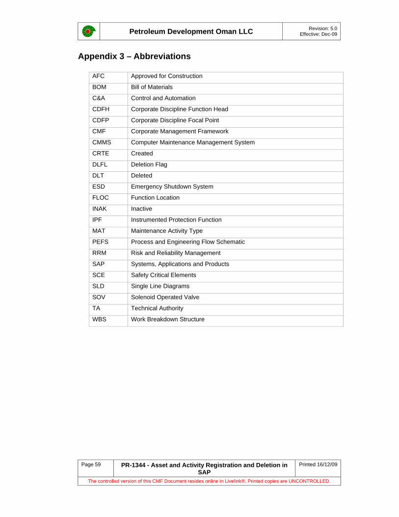
Petroleum Development Oman LLC Revision: 5.0 Effective: Dec-09
Page 59 PR-1344 - Asset and Activity Registration and Deletion in SAP
Printed 16/12/09
The controlled version of this CMF Document resides online in Livelink®. Printed copies are UNCONTROLLED.
Appendix 3 – Abbreviations
AFC Approved for Construction
BOM Bill of Materials
C&A Control and Automation
CDFH Corporate Discipline Function Head
CDFP Corporate Discipline Focal Point
CMF Corporate Management Framework
CMMS Computer Maintenance Management System
CRTE Created
DLFL Deletion Flag
DLT Deleted
ESD Emergency Shutdown System
FLOC Function Location
INAK Inactive
IPF Instrumented Protection Function
MAT Maintenance Activity Type
PEFS Process and Engineering Flow Schematic
RRM Risk and Reliability Management
SAP Systems, Applications and Products
SCE Safety Critical Elements
SLD Single Line Diagrams
SOV Solenoid Operated Valve
TA Technical Authority
WBS Work Breakdown Structure

Petroleum Development Oman LLC Revision: 5.0 Effective: Dec-09
Page 60 PR-1344 - Asset and Activity Registration and Deletion in SAP
Printed 16/12/09
The controlled version of this CMF Document resides online in Livelink®. Printed copies are UNCONTROLLED.
Appendix 4 – Responsibilities Flow Chart
Area
Pro
j. / F
low
line
Eng'
rSA
P PM
Mas
ter D
ata
Supp
.C
DFP
s /
Area
Mnt
Eng
'rs.
Area
Ass
et H
olde
rEN
D
No Activity Description 1 2 3 4 5
1 Project Design Scope
2Initiate Data entry process - Filling in of Master Data Loading Forms, Provide PEFS, Vendors details etc.
3 Master Data Loading in SAP
4 Initiation of Standard Text, TaskList and Maintenance Plans.
5 Loading Standard Text, TaskList and Maintenance Plans.
6Plan and Scheduling Maintenance Plans for new Equipment.
7Audit data availability and quality and feedback non-compliance to asset holder.
8 Maintain accuracy of asset and activity data through out equip. lifetime. Re-initiate data entry process as required
9 End of Process

Petroleum Development Oman LLC Revision: 5.0 Effective: Dec-09
Page 61 PR-1344 - Asset and Activity Registration and Deletion in SAP
Printed 16/12/09
The controlled version of this CMF Document resides online in Livelink®. Printed copies are UNCONTROLLED.
Appendix 5 - User Feedback Page
PR-1344 – Asset and Activity Registration and Deletion in SAP User Feedback Page
Any user who identifies an inaccuracy, error or ambiguity is requested to notify the custodian so that appropriate action can be taken. The user is requested to return this page fully completed, indicating precisely the amendment(s) recommended.
Name:
Ref ID Date:
Page Ref: Brief Description of Change Required and Reasons
UOM3
Custodian of Document Date:
Scope of work for CMMS and CCMS
Doc. No: ZAU-84-104810 -VA-6793-20001-0000
APPENDIX-II
REVISION: 02 Date: 03.06.2013
APPENDIX II
Selection of Safety Critical Elements (SCE) and Development of Performance Stds (PS) & PS Assurance Tasks

Scope of work for CMMS and CCMS
Doc. No: ZAU-84-104810 -VA-6793-20001-0000
APPENDIX-III
REVISION: 02 Date: 03.06.2013
APPENDIX III
ENGINEERING AND OPERATIONS PROCEDURE FOR Z6 NOTIFICATION
This document is the property of Petroleum Development Oman, LLC. Neither the whole nor any part of this document may be disclosed to others or reproduced, stored in a retrieval system, or transmitted in any form by any means (electronic, mechanical, reprographic recording or otherwise) without prior written consent of the owner.
Petroleum Development Oman L.L.C.
Engineering and Operations
Procedure for Z6 Notification
User Note:
The requirements of this document are mandatory. Non-compliance shall only be authorised by the Document Owner or his Delegate through STEP-OUT approval.
A controlled copy of the current version of this document is on PDO's EDMS. Before making reference to this document, it is the user's responsibility to ensure that any hard copy, or electronic copy, is current. For assistance, contact the Document Custodian or the Document Controller.
Users are encouraged to participate in the ongoing improvement of this document by providing constructive feedback.
Please familiarise yourself with the Document Security Classification Definitions
They apply to this Document!
UNRESTRICTED Document ID: PR-1528 Jan-10 Filing Key: Business Control

Petroleum Development Oman LLC Revision: 3.0 Effective:Jan-10
Page 2 PR-1528 – Z6 Notification Printed 11/01/10 The controlled version of this CMF Document resides online in Livelink®. Printed copies are UNCONTROLLED.
This page was intentionally left blank

Petroleum Development Oman LLC Revision: 3.0 Effective:Jan-10
Page 3 PR-1528 – Z6 Notification Printed 11/01/10 The controlled version of this CMF Document resides online in Livelink®. Printed copies are UNCONTROLLED.
i Document Authorisation Authorised For Issue – January 2010
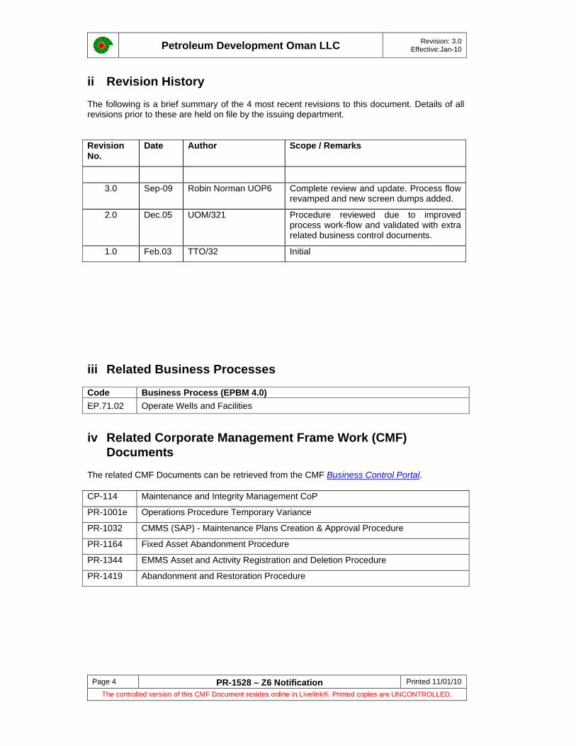
Petroleum Development Oman LLC Revision: 3.0 Effective:Jan-10
Page 4 PR-1528 – Z6 Notification Printed 11/01/10 The controlled version of this CMF Document resides online in Livelink®. Printed copies are UNCONTROLLED.
ii Revision History
The following is a brief summary of the 4 most recent revisions to this document. Details of all revisions prior to these are held on file by the issuing department. Revision No.
Date Author Scope / Remarks
3.0 Sep-09 Robin Norman UOP6 Complete review and update. Process flow revamped and new screen dumps added.
2.0 Dec.05 UOM/321 Procedure reviewed due to improved process work-flow and validated with extra related business control documents.
1.0 Feb.03 TTO/32 Initial
iii Related Business Processes
Code Business Process (EPBM 4.0)EP.71.02 Operate Wells and Facilities
iv Related Corporate Management Frame Work (CMF) Documents
The related CMF Documents can be retrieved from the CMF Business Control Portal.
CP-114 Maintenance and Integrity Management CoP
PR-1001e Operations Procedure Temporary Variance
PR-1032 CMMS (SAP) - Maintenance Plans Creation & Approval Procedure
PR-1164 Fixed Asset Abandonment Procedure
PR-1344 EMMS Asset and Activity Registration and Deletion Procedure
PR-1419 Abandonment and Restoration Procedure

Petroleum Development Oman LLC Revision: 3.0 Effective:Jan-10
Page 5 PR-1528 – Z6 Notification Printed 11/01/10 The controlled version of this CMF Document resides online in Livelink®. Printed copies are UNCONTROLLED.
TABLE OF CONTENTS 1 Introduction ............................................................................................................................ 6
1.1 Background ...................................................................................................................... 6 1.2 Purpose ............................................................................................................................ 6 1.3 Scope ............................................................................................................................... 6 1.4 Distribution / Target Audience .......................................................................................... 6 1.5 Review and Improvement ................................................................................................ 6 1.6 Step-Out and Approval ..................................................................................................... 6
2 Roles and Responsibilities ..................................................................................................... 7 3 Z6 Notification Processes ...................................................................................................... 8
3.1 Scope ............................................................................................................................... 8 3.2 Overall Process ................................................................................................................ 9 Figure 1 – Z6 Notification Process (Simplified) ......................................................................... 9 3.3 Creating New SAP-PM Master Data Record ................................................................. 11 3.4 Updating SAP-PM Master Data Record – Equipment Movement ................................. 14 3.5 Updating SAP-PM Master Data Record – Redundancy / Write-off of Equipment ......... 15 3.6 Creation of New, or Change to Existing Maintenance Plans ......................................... 15
3.6.1 Creation of a Maintenance Plan for New Equipment .............................................. 16 3.6.2 Rescheduling of Maintenance Plan ......................................................................... 16 3.6.3 Adding or Removing Maintenance Packages when Strategy Changes .................. 17 3.6.4 Suspension of Maintenance Plan ............................................................................ 17 3.6.5 Activating a Suspended Maintenance Plan ............................................................. 17 3.6.6 Additions and / or Deletions from the Task List ....................................................... 17
3.7 Cancelling and Deleting a Z6 Notification ...................................................................... 18 4 Monitoring and Compliance ................................................................................................. 21
4.1 Key Performance Monitoring (KPIs) .............................................................................. 21 4.2 Compliance .................................................................................................................... 21
Appendix 1 – SAP-PM Master Data Codes and Work Centres .................................................. 22 Appendix 2 – Data Entry Templates ........................................................................................... 24 Appendix 2 – Abbreviations ........................................................................................................ 25 Appendix 3 - User Feedback Page ............................................................................................. 26
Tables and Figures Figure 1 – Z6 Notification Process (Simplified) ............................................................................. 9

Petroleum Development Oman LLC Revision: 3.0 Effective:Jan-10
Page 6 PR-1528 – Z6 Notification Printed 11/01/10 The controlled version of this CMF Document resides online in Livelink®. Printed copies are UNCONTROLLED.
1 Introduction
1.1 Background The Asset Register Is a complete and detailed overview of all physical (tangible) assets that are fully or partially owned by PDO and that represent value and/or have related costs. The Asset Register is held in SAP-PM.
For new builds and modifications the register is compiled and handed over as one of the ‘key deliverables’. Throughout the life of the asset changes are recorded to the register. With regard to Plant Maintenance the Asset Register shall contain SAP-PM Master Data on all equipment installed within the asset.
The Z6 Notification is used to record requests made to update SAP-PM Master Data i.e. creation of new SAP-PM Master Data (e.g. Asset registration for new projects), or change to existing SAP Master Data (e.g. Equipment Movement from one location to other, change of Maintenance Plan, etc.), or correction of errors in the Master Data The Z6 Notification shall also provide the necessary audit trail required to demonstrate Asset Integrity.
1.2 Purpose The purpose of the procedure is to ensure that changes to SAP-PM Master Data are carried out correctly and in accordance with SAP requirements.
1.3 Scope This procedure shall cover corrections and additions to SAP-PM Master Data that are eligible using the Z6 Notification process.
1.4 Distribution / Target Audience The procedure is intended to be referenced and used by Field Operations and Maintenance Teams, Work Schedulers, Asset Planners, Corporate Discipline Focal Points and Project Managers. It should also be made available as a source of reference to Engineering and Maintenance Contractors (EMC), and Offplot Development Contractors (ODC).
1.5 Review and Improvement This document shall be subject to review by the Document Owner / Document Custodian every 3 years from the last date of issue.
At any time during this period the document ‘Users’ may request the contents to be reviewed and revised. Requests for review and revision shall be made in writing to the Document Custodian using the ‘User Feedback Page’ or by sending a ‘Marked Up’ copy of the document. The decision to review or revise the document shall rest with the Functional Maintenance & Integrity Manager (UOM), the Owner.
1.6 Step-Out and Approval This Document is Mandatory. Step-Out shall be in accordance with PR-1001e – Operations Procedure Temporary Variance.

Petroleum Development Oman LLC Revision: 3.0 Effective:Jan-10
Page 7 PR-1528 – Z6 Notification Printed 11/01/10 The controlled version of this CMF Document resides online in Livelink®. Printed copies are UNCONTROLLED.
2 Roles and Responsibilities
The following table lists the Roles and Responsibilities for the Key Personnel.
Role Responsibility
Initiator – Any PDO / Contractor personnel with Access to SAP-PM
• Raises the Z6 Notification and shall:
- provide clear long text description of actual Master Data
- change required (with attachments as required)
- - assign correct work centre identification
- - use correct standard codes to categorise type of Master Data being changed
Initial Reviewer – Tech. Reliability / Integrity Engineer, Asset Owner, Maintenance Engineers, Support / Project Engineers / Flowline Engineers
• Reviews the Z6 Notification in accordance with SAP Master Data requirements
• Provides any additional information as required for the relevant information
• Provide advice on Maintenance Plan data as required when creating new equipment entries
• Provide Maintenance Plan ‘start’ date and frequency required
• Forwards Z6 Notification to CDFP for approval
• Reject (cancel) Z6 Notification if not valid
Approver – Corporate Discipline Focal Point (refer to Appendix 1 Work Centres Codes for CDFP’s)
• Review details of the Z6 Notification in accordance with SAP Master Data requirements
• Assess the impact or risk of the proposed data changes
• Make recommendation where applicable to standardise or extend Z6 Notification changes throughout all PDO Assets
• Reject the Z6 Notification if not justifies
• Approve implementation of the notification
• Review the Master data records once implemented in SAP-PM
• Close out Z6 Notification request
Data Input to SAP-PM - Head SAP-PM Master Data Management
• Correct as required Master Data standard codes if incorrectly categorised by initiator
• Apply the approved changes to SAP-PM Master Data
• Refer and request any additional or missing information from CDFP, Reviewers, and / or Initiator as required to apply changes to SAP-PM Master Data
• Request ‘close out’ from CDFP when all updating has been completed
Petroleum Development Oman LLC Revision: 3.0 Effective:Jan-10
Page 8 PR-1528 – Z6 Notification Printed 11/01/10 The controlled version of this CMF Document resides online in Livelink®. Printed copies are UNCONTROLLED.
3 Z6 Notification Processes
3.1 Scope The procedure shall address the following Z6 Notification processes:
• Creating New SAP-PM Master Data (Assets and Facilities)
• Movement of equipment to different or between location
• Redundancy / Write-off of equipment (Planned Maintenance routines only)
• Creation of New, or Change to existing Maintenance Plans
• Cancelling and Deleting a Z6 Notification
The remainder of this page Intentionally Left Blank
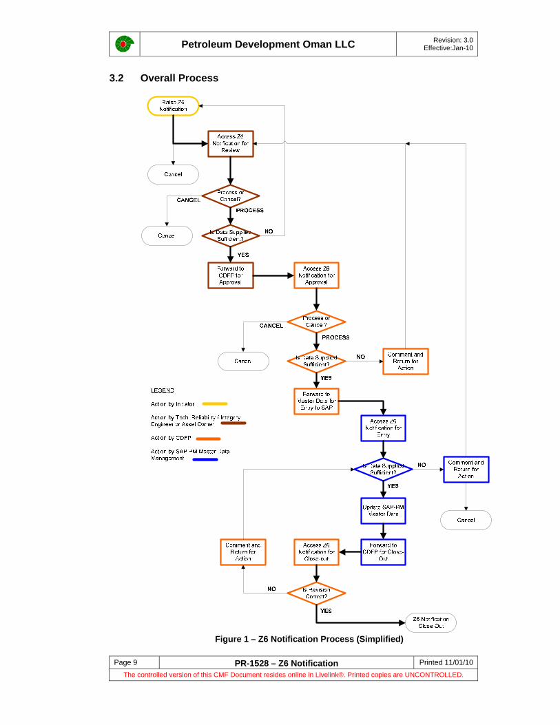
Petroleum Development Oman LLC Revision: 3.0 Effective:Jan-10
Page 9 PR-1528 – Z6 Notification Printed 11/01/10 The controlled version of this CMF Document resides online in Livelink®. Printed copies are UNCONTROLLED.
3.2 Overall Process
Figure 1 – Z6 Notification Process (Simplified)

Petroleum Development Oman LLC Revision: 3.0 Effective:Jan-10
Page 10 PR-1528 – Z6 Notification Printed 11/01/10 The controlled version of this CMF Document resides online in Livelink®. Printed copies are UNCONTROLLED.
The overall Z6 Notification process is illustrated in Figure 1. Definitions of User Status can be referenced in Appendix *.
The Z6 Notification is raised in the Work Centre (refer to Appendix ) for the CDFP who shall be responsible for Approval.
1. • Initiator (any person with SAP-PM access) raises the Z6 Notification in the respective Work Centre and enters the required data
USER Status INIT
2. • Reviewer changes user status
USER Status INIT NVST
3. • Tech. Reliability / Integrity Engineer, Asset Owner, RV Workshop and Maintenance Engineer searches SAP-PM for Z6 Notification (in respective Work Centre) for INIT
• Provide additional data as required.
• Request more data from Initiator if required. Changes User Status to INIT.NVST. Initiator shall provide required data
• Decision made to Process or Cancel
4. Tech. Reliability / Integrity Engineer or Asset Owner changes user status
USER Status AWAP
5. • CDFP searches SAP-PM for Z6 Notification (in respective Work Centre) for AWAP
• Decides if data is sufficient.
• If insufficient, adds comments and changes User Status to AWAP NVST. Tech. Reliability / Integrity Engineer or Asset Owner to provide required data
• Decision made to Process or Cancel
6. CDFP changes user status
USER Status APPR
7. • SAP-PM Master Data Management Team searches SAP-PM for Z6 Notification (in respective Work Centre) for APPR
• Decides if data is sufficient.
• If insufficient, adds comments and changes User Status to APPR NVST. Initiator, Reviewer (Tech. Reliability / Integrity Engineer, Asset Owner, RV Workshop and Maintenance Engineer), or CDFP shall provide required data OR Cancels the process
• If data sufficient SAP-PM Master Data Management Team update SAP-PM Master Data
USER Status APPR
8. • SAP-PM Master Data Management Team changes user status
USER Status TBCO
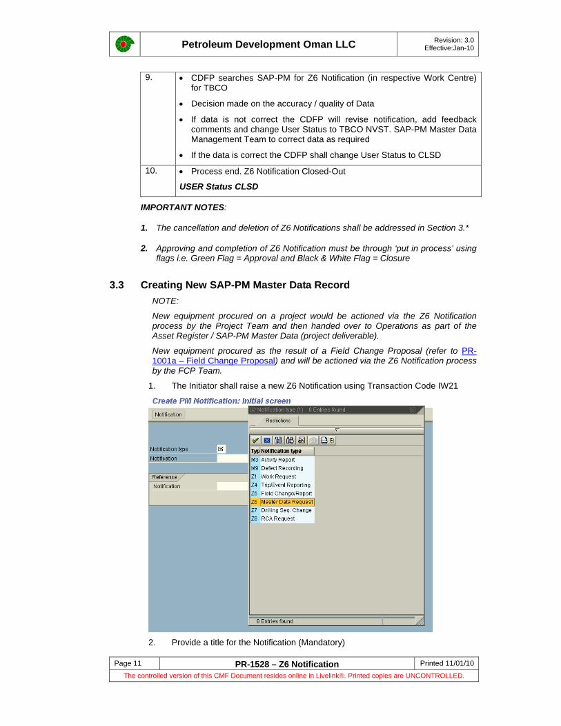
Petroleum Development Oman LLC Revision: 3.0 Effective:Jan-10
Page 11 PR-1528 – Z6 Notification Printed 11/01/10 The controlled version of this CMF Document resides online in Livelink®. Printed copies are UNCONTROLLED.
9. • CDFP searches SAP-PM for Z6 Notification (in respective Work Centre) for TBCO
• Decision made on the accuracy / quality of Data
• If data is not correct the CDFP will revise notification, add feedback comments and change User Status to TBCO NVST. SAP-PM Master Data Management Team to correct data as required
• If the data is correct the CDFP shall change User Status to CLSD
10. • Process end. Z6 Notification Closed-Out
USER Status CLSD
IMPORTANT NOTES:
1. The cancellation and deletion of Z6 Notifications shall be addressed in Section 3.*
2. Approving and completion of Z6 Notification must be through ‘put in process’ using flags i.e. Green Flag = Approval and Black & White Flag = Closure
3.3 Creating New SAP-PM Master Data Record NOTE:
New equipment procured on a project would be actioned via the Z6 Notification process by the Project Team and then handed over to Operations as part of the Asset Register / SAP-PM Master Data (project deliverable).
New equipment procured as the result of a Field Change Proposal (refer to PR-1001a – Field Change Proposal) and will be actioned via the Z6 Notification process by the FCP Team.
1. The Initiator shall raise a new Z6 Notification using Transaction Code IW21
2. Provide a title for the Notification (Mandatory)
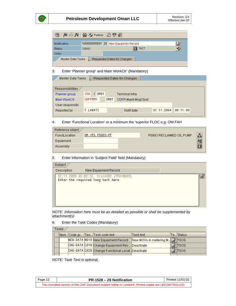
Petroleum Development Oman LLC Revision: 3.0 Effective:Jan-10
Page 12 PR-1528 – Z6 Notification Printed 11/01/10 The controlled version of this CMF Document resides online in Livelink®. Printed copies are UNCONTROLLED.
3. Enter ‘Planner group’ and Main WorkCtr’ (Mandatory)
4. Enter ‘Functional Location’ or a minimum the ‘superior FLOC e.g. OM.FAH
5. Enter information in ‘Subject Field’ field (Mandatory)
NOTE: Information here must be as detailed as possible or shall be supplemented by attachment(s)
6. Enter the Task Codes (Mandatory)
NOTE: Task Text is optional.
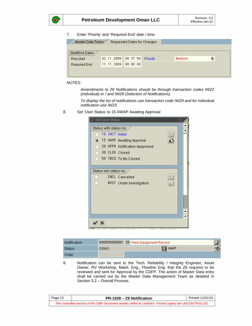
Petroleum Development Oman LLC Revision: 3.0 Effective:Jan-10
Page 13 PR-1528 – Z6 Notification Printed 11/01/10 The controlled version of this CMF Document resides online in Livelink®. Printed copies are UNCONTROLLED.
7. Enter ‘Priority’ and ‘Required End’ date / time
NOTES:
Amendments to Z6 Notifications should be through transaction codes IW22 (individual) or / and IW28 (Selection of Notifications).
To display the list of notifications use transaction code IW29 and for individual notification use IW23.
8. Set ‘User Status’ to 15 AWAP Awaiting Approval
9. Notification can be sent to the Tech. Reliability / Integrity Engineer, Asset
Owner, RV Workshop, Maint. Eng., Flowline Eng. that the Z6 requires to be reviewed and sent for Approval by the CDFP. The action of Master Data entry shall be carried out by the Master Data Management Team as detailed in Section 3.2 – Overall Process.
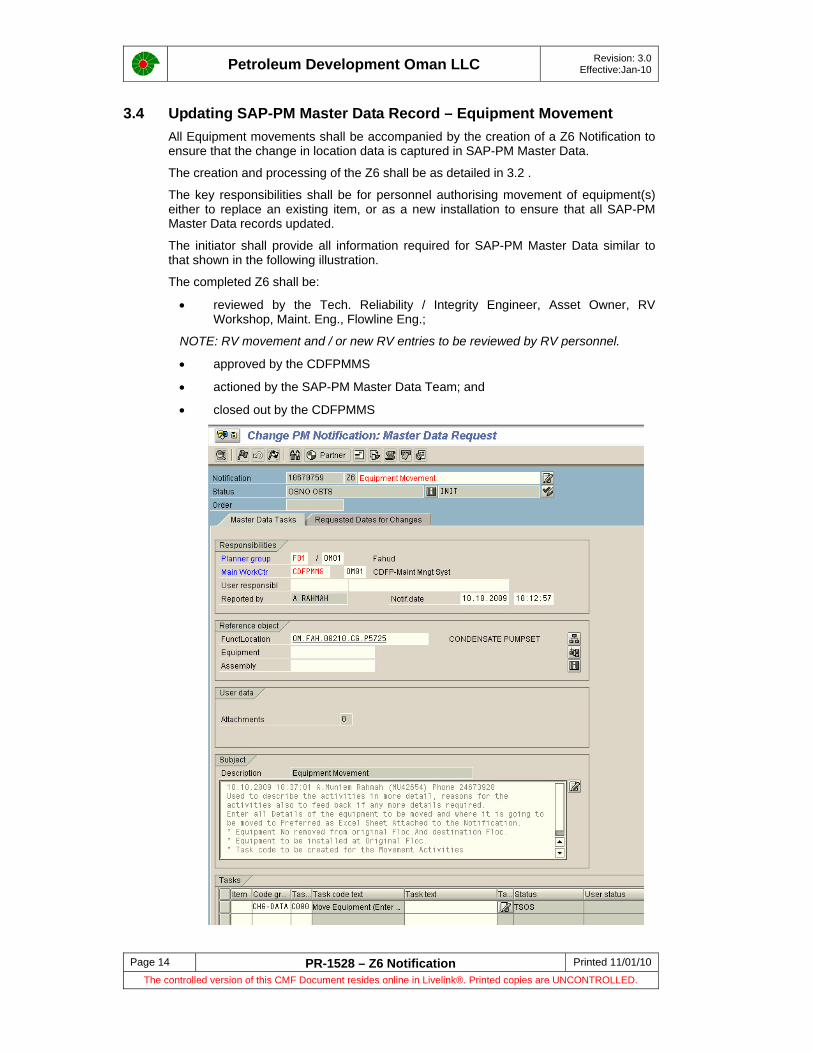
Petroleum Development Oman LLC Revision: 3.0 Effective:Jan-10
Page 14 PR-1528 – Z6 Notification Printed 11/01/10 The controlled version of this CMF Document resides online in Livelink®. Printed copies are UNCONTROLLED.
3.4 Updating SAP-PM Master Data Record – Equipment Movement All Equipment movements shall be accompanied by the creation of a Z6 Notification to ensure that the change in location data is captured in SAP-PM Master Data.
The creation and processing of the Z6 shall be as detailed in 3.2 .
The key responsibilities shall be for personnel authorising movement of equipment(s) either to replace an existing item, or as a new installation to ensure that all SAP-PM Master Data records updated.
The initiator shall provide all information required for SAP-PM Master Data similar to that shown in the following illustration.
The completed Z6 shall be:
• reviewed by the Tech. Reliability / Integrity Engineer, Asset Owner, RV Workshop, Maint. Eng., Flowline Eng.;
NOTE: RV movement and / or new RV entries to be reviewed by RV personnel.
• approved by the CDFPMMS
• actioned by the SAP-PM Master Data Team; and
• closed out by the CDFPMMS

Petroleum Development Oman LLC Revision: 3.0 Effective:Jan-10
Page 15 PR-1528 – Z6 Notification Printed 11/01/10 The controlled version of this CMF Document resides online in Livelink®. Printed copies are UNCONTROLLED.
3.5 Updating SAP-PM Master Data Record – Redundancy / Write-off of Equipment Equipment Abandonment, Redundancy or Write-Off shall be undertaken in accordance with the following procedures:
PR-1164 - Fixed Asset Abandonment Procedure
PR-1419 – Abandonment and Restoration
SAP-PM Master Data changes that result should be managed through Z6 Notification. Function teams and individuals who have the authority to authorise abandonment / redundancy or write-off of equipment shall ensure that this requirement is adhered to.
The long text shall clearly state:
• The Equipment No. of the item being moved;
• The original FLOC, and the destination FLOC to which it will be moved to e.g. Write-off yards.
• Function Location list of all associated equipment being moved (maybe added as an attachment if large)
• Task codes i.e.
If Equipment is redundant and can be re-used and requires to be moved to another location then Section 3.4 shall be referenced.
Equipment that has been made redundant or is no longer uses (bypassed) shall be temporarily “De-Activated” with the system status code INAK allocated by the SAP-PM Master Data Management Team. Should the equipment be isolated and chemically preserved (mothballed) the system status code MOTH allocated.
A decision to ‘write-off’ the equipment shall require a completed “Write Off Form” signed and approved. The SAP-PM Master Data Management Team to change the system status code to INAK. After removing the Asset from PDO the Master Data Management Team change the status code to INAK DLFL and change the Location Code from MUSWOF to OM000 (dedicated location in SAP for written off assets).
NOTE: It is the responsibility SAP-PM Data Management Team to inform Asset Accounting Team on all asset redundancy requests completed via Z6, only after obtaining approval to remove the Asset from PM data.
3.6 Creation of New, or Change to Existing Maintenance Plans The creation and processing of the Z6 shall be as detailed in 3.2.
The responsibility for creating, changing and quality checking Maintenance Plans shall be the Asset Owners, but shall in the most part a collaborative exercise between the former and the Maintenance Supervisor, Tech. Reliability / Integrity Engineer, Area Planner, Work Scheduler and CDFP’s.
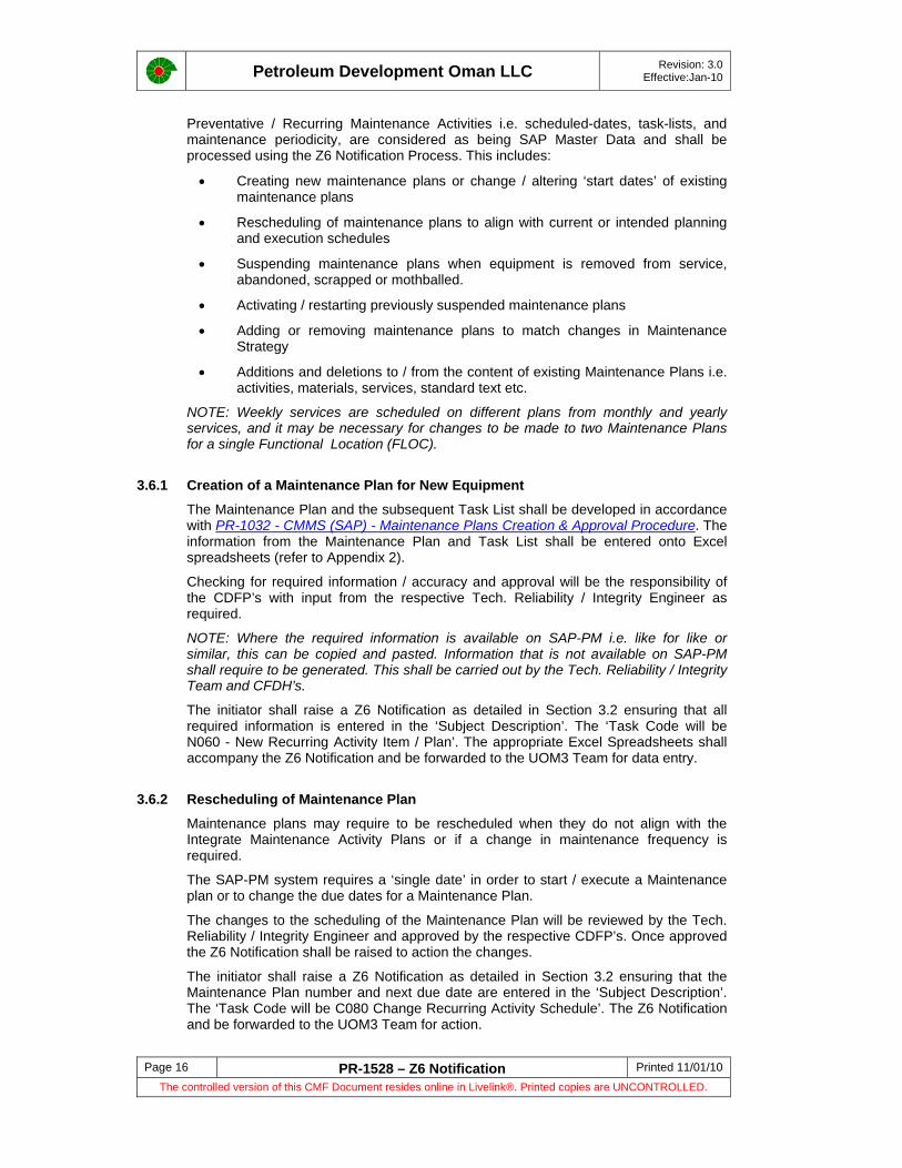
Petroleum Development Oman LLC Revision: 3.0 Effective:Jan-10
Page 16 PR-1528 – Z6 Notification Printed 11/01/10 The controlled version of this CMF Document resides online in Livelink®. Printed copies are UNCONTROLLED.
Preventative / Recurring Maintenance Activities i.e. scheduled-dates, task-lists, and maintenance periodicity, are considered as being SAP Master Data and shall be processed using the Z6 Notification Process. This includes:
• Creating new maintenance plans or change / altering ‘start dates’ of existing maintenance plans
• Rescheduling of maintenance plans to align with current or intended planning and execution schedules
• Suspending maintenance plans when equipment is removed from service, abandoned, scrapped or mothballed.
• Activating / restarting previously suspended maintenance plans
• Adding or removing maintenance plans to match changes in Maintenance Strategy
• Additions and deletions to / from the content of existing Maintenance Plans i.e. activities, materials, services, standard text etc.
NOTE: Weekly services are scheduled on different plans from monthly and yearly services, and it may be necessary for changes to be made to two Maintenance Plans for a single Functional Location (FLOC).
3.6.1 Creation of a Maintenance Plan for New Equipment
The Maintenance Plan and the subsequent Task List shall be developed in accordance with PR-1032 - CMMS (SAP) - Maintenance Plans Creation & Approval Procedure. The information from the Maintenance Plan and Task List shall be entered onto Excel spreadsheets (refer to Appendix 2).
Checking for required information / accuracy and approval will be the responsibility of the CDFP’s with input from the respective Tech. Reliability / Integrity Engineer as required.
NOTE: Where the required information is available on SAP-PM i.e. like for like or similar, this can be copied and pasted. Information that is not available on SAP-PM shall require to be generated. This shall be carried out by the Tech. Reliability / Integrity Team and CFDH’s.
The initiator shall raise a Z6 Notification as detailed in Section 3.2 ensuring that all required information is entered in the ‘Subject Description’. The ‘Task Code will be N060 - New Recurring Activity Item / Plan’. The appropriate Excel Spreadsheets shall accompany the Z6 Notification and be forwarded to the UOM3 Team for data entry.
3.6.2 Rescheduling of Maintenance Plan
Maintenance plans may require to be rescheduled when they do not align with the Integrate Maintenance Activity Plans or if a change in maintenance frequency is required.
The SAP-PM system requires a ‘single date’ in order to start / execute a Maintenance plan or to change the due dates for a Maintenance Plan.
The changes to the scheduling of the Maintenance Plan will be reviewed by the Tech. Reliability / Integrity Engineer and approved by the respective CDFP’s. Once approved the Z6 Notification shall be raised to action the changes.
The initiator shall raise a Z6 Notification as detailed in Section 3.2 ensuring that the Maintenance Plan number and next due date are entered in the ‘Subject Description’. The ‘Task Code will be C080 Change Recurring Activity Schedule’. The Z6 Notification and be forwarded to the UOM3 Team for action.
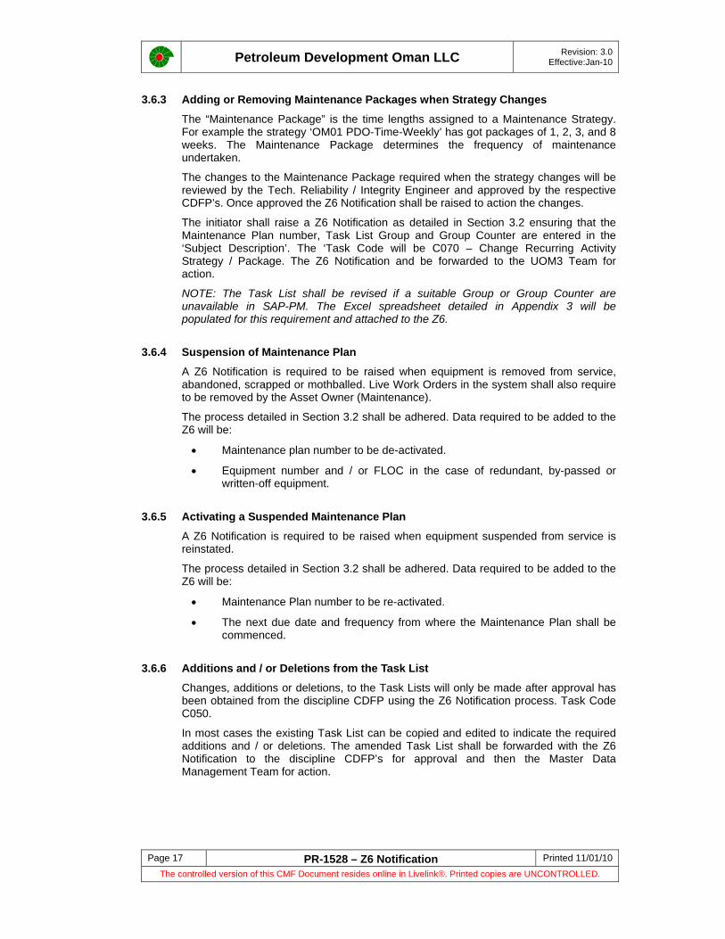
Petroleum Development Oman LLC Revision: 3.0 Effective:Jan-10
Page 17 PR-1528 – Z6 Notification Printed 11/01/10 The controlled version of this CMF Document resides online in Livelink®. Printed copies are UNCONTROLLED.
3.6.3 Adding or Removing Maintenance Packages when Strategy Changes
The “Maintenance Package” is the time lengths assigned to a Maintenance Strategy. For example the strategy ‘OM01 PDO-Time-Weekly’ has got packages of 1, 2, 3, and 8 weeks. The Maintenance Package determines the frequency of maintenance undertaken.
The changes to the Maintenance Package required when the strategy changes will be reviewed by the Tech. Reliability / Integrity Engineer and approved by the respective CDFP’s. Once approved the Z6 Notification shall be raised to action the changes.
The initiator shall raise a Z6 Notification as detailed in Section 3.2 ensuring that the Maintenance Plan number, Task List Group and Group Counter are entered in the ‘Subject Description’. The ‘Task Code will be C070 – Change Recurring Activity Strategy / Package. The Z6 Notification and be forwarded to the UOM3 Team for action.
NOTE: The Task List shall be revised if a suitable Group or Group Counter are unavailable in SAP-PM. The Excel spreadsheet detailed in Appendix 3 will be populated for this requirement and attached to the Z6.
3.6.4 Suspension of Maintenance Plan
A Z6 Notification is required to be raised when equipment is removed from service, abandoned, scrapped or mothballed. Live Work Orders in the system shall also require to be removed by the Asset Owner (Maintenance).
The process detailed in Section 3.2 shall be adhered. Data required to be added to the Z6 will be:
• Maintenance plan number to be de-activated.
• Equipment number and / or FLOC in the case of redundant, by-passed or written-off equipment.
3.6.5 Activating a Suspended Maintenance Plan
A Z6 Notification is required to be raised when equipment suspended from service is reinstated.
The process detailed in Section 3.2 shall be adhered. Data required to be added to the Z6 will be:
• Maintenance Plan number to be re-activated.
• The next due date and frequency from where the Maintenance Plan shall be commenced.
3.6.6 Additions and / or Deletions from the Task List
Changes, additions or deletions, to the Task Lists will only be made after approval has been obtained from the discipline CDFP using the Z6 Notification process. Task Code C050.
In most cases the existing Task List can be copied and edited to indicate the required additions and / or deletions. The amended Task List shall be forwarded with the Z6 Notification to the discipline CDFP’s for approval and then the Master Data Management Team for action.

Petroleum Development Oman LLC Revision: 3.0 Effective:Jan-10
Page 18 PR-1528 – Z6 Notification Printed 11/01/10 The controlled version of this CMF Document resides online in Livelink®. Printed copies are UNCONTROLLED.
3.7 Cancelling and Deleting a Z6 Notification The following procedure shall be followed to cancel and delete a Z6 Notification.
1. Enter Transaction IW22 to change / amend Z6 Notification
2. Set CNCL Status by clicking either the status detail button flag (to cancel status click back button)
OR
Set status button flag to ‘CANCEL’ status and click button.
“Status Detail” “Set Status” Button
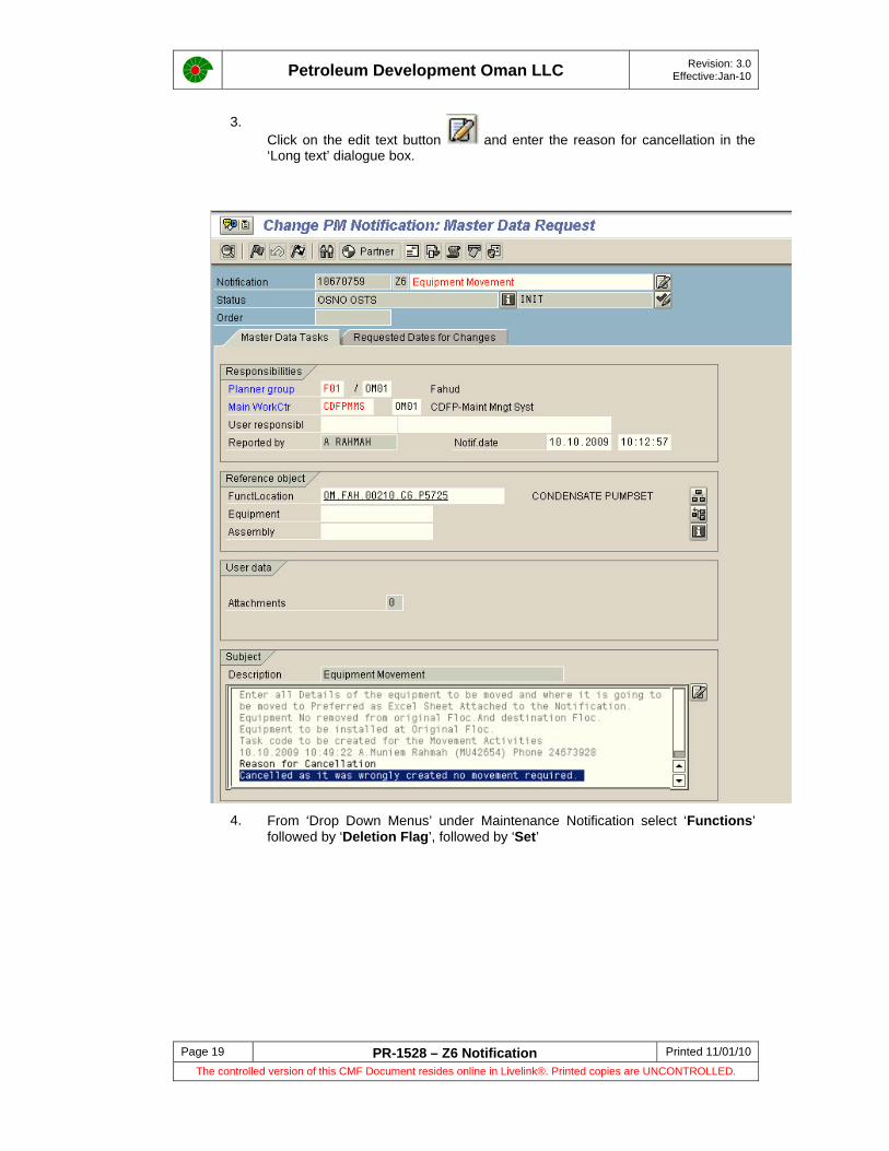
Petroleum Development Oman LLC Revision: 3.0 Effective:Jan-10
Page 19 PR-1528 – Z6 Notification Printed 11/01/10 The controlled version of this CMF Document resides online in Livelink®. Printed copies are UNCONTROLLED.
3. Click on the edit text button and enter the reason for cancellation in the ‘Long text’ dialogue box.
4. From ‘Drop Down Menus’ under Maintenance Notification select ‘Functions’
followed by ‘Deletion Flag’, followed by ‘Set’

Petroleum Development Oman LLC Revision: 3.0 Effective:Jan-10
Page 20 PR-1528 – Z6 Notification Printed 11/01/10 The controlled version of this CMF Document resides online in Livelink®. Printed copies are UNCONTROLLED.
5. This completes the Cancel / Deletion process
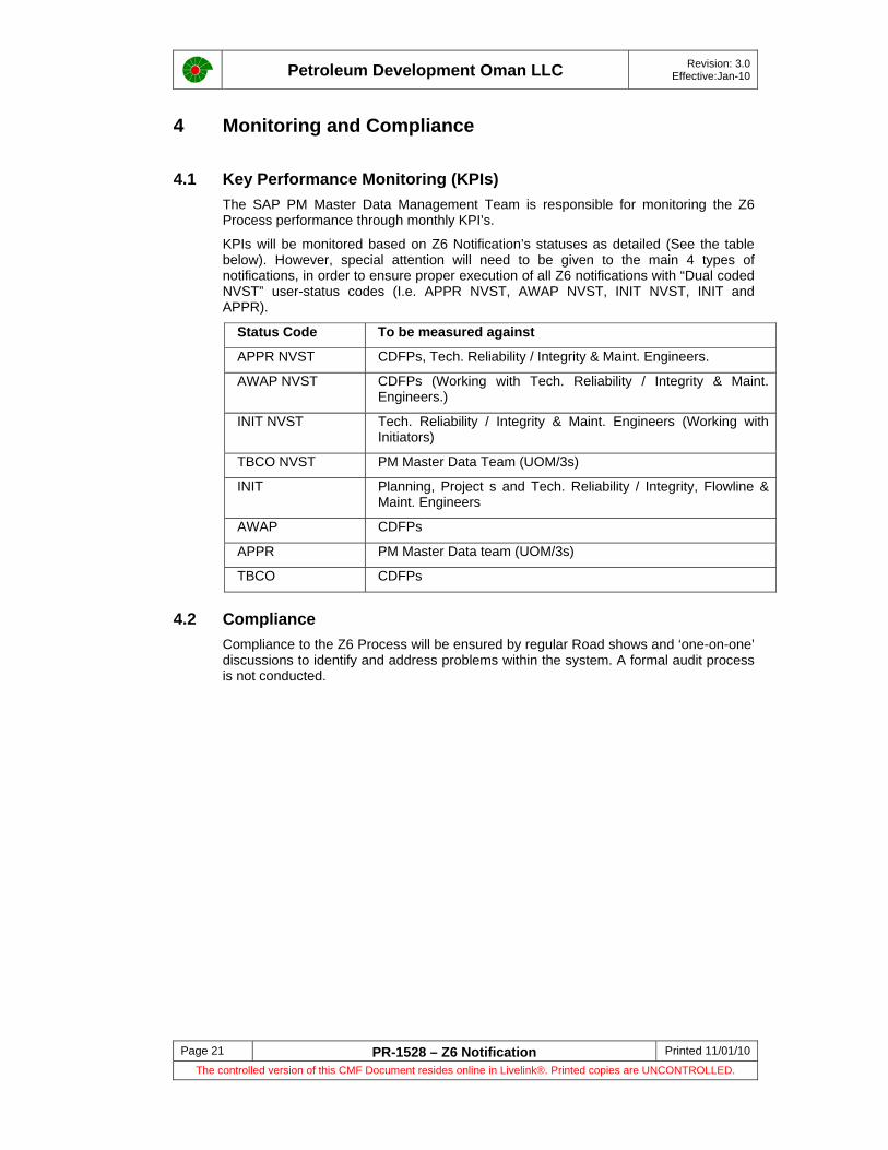
Petroleum Development Oman LLC Revision: 3.0 Effective:Jan-10
Page 21 PR-1528 – Z6 Notification Printed 11/01/10 The controlled version of this CMF Document resides online in Livelink®. Printed copies are UNCONTROLLED.
4 Monitoring and Compliance
4.1 Key Performance Monitoring (KPIs) The SAP PM Master Data Management Team is responsible for monitoring the Z6 Process performance through monthly KPI’s.
KPIs will be monitored based on Z6 Notification’s statuses as detailed (See the table below). However, special attention will need to be given to the main 4 types of notifications, in order to ensure proper execution of all Z6 notifications with “Dual coded NVST” user-status codes (I.e. APPR NVST, AWAP NVST, INIT NVST, INIT and APPR).
Status Code To be measured against
APPR NVST CDFPs, Tech. Reliability / Integrity & Maint. Engineers.
AWAP NVST CDFPs (Working with Tech. Reliability / Integrity & Maint. Engineers.)
INIT NVST Tech. Reliability / Integrity & Maint. Engineers (Working with Initiators)
TBCO NVST PM Master Data Team (UOM/3s)
INIT Planning, Project s and Tech. Reliability / Integrity, Flowline & Maint. Engineers
AWAP CDFPs
APPR PM Master Data team (UOM/3s)
TBCO CDFPs
4.2 Compliance Compliance to the Z6 Process will be ensured by regular Road shows and ‘one-on-one’ discussions to identify and address problems within the system. A formal audit process is not conducted.
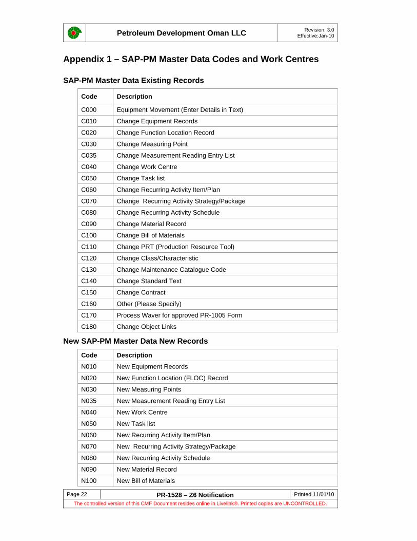
Petroleum Development Oman LLC Revision: 3.0 Effective:Jan-10
Page 22 PR-1528 – Z6 Notification Printed 11/01/10 The controlled version of this CMF Document resides online in Livelink®. Printed copies are UNCONTROLLED.
Appendix 1 – SAP-PM Master Data Codes and Work Centres
SAP-PM Master Data Existing Records
Code Description
C000 Equipment Movement (Enter Details in Text)
C010 Change Equipment Records
C020 Change Function Location Record
C030 Change Measuring Point
C035 Change Measurement Reading Entry List
C040 Change Work Centre
C050 Change Task list
C060 Change Recurring Activity Item/Plan
C070 Change Recurring Activity Strategy/Package
C080 Change Recurring Activity Schedule
C090 Change Material Record
C100 Change Bill of Materials
C110 Change PRT (Production Resource Tool)
C120 Change Class/Characteristic
C130 Change Maintenance Catalogue Code
C140 Change Standard Text
C150 Change Contract
C160 Other (Please Specify)
C170 Process Waver for approved PR-1005 Form
C180 Change Object Links
New SAP-PM Master Data New Records
Code Description
N010 New Equipment Records
N020 New Function Location (FLOC) Record
N030 New Measuring Points
N035 New Measurement Reading Entry List
N040 New Work Centre
N050 New Task list
N060 New Recurring Activity Item/Plan
N070 New Recurring Activity Strategy/Package
N080 New Recurring Activity Schedule
N090 New Material Record
N100 New Bill of Materials
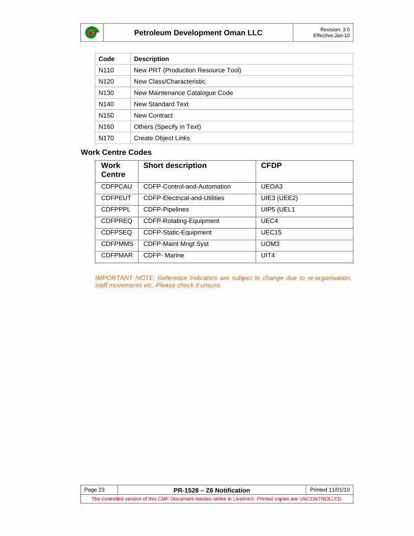
Petroleum Development Oman LLC Revision: 3.0 Effective:Jan-10
Page 23 PR-1528 – Z6 Notification Printed 11/01/10 The controlled version of this CMF Document resides online in Livelink®. Printed copies are UNCONTROLLED.
Code Description
N110 New PRT (Production Resource Tool)
N120 New Class/Characteristic
N130 New Maintenance Catalogue Code
N140 New Standard Text
N150 New Contract
N160 Others (Specify in Text)
N170 Create Object Links
Work Centre Codes Work Centre
Short description CFDP
CDFPCAU CDFP-Control-and-Automation UEOA3
CDFPEUT CDFP-Electrical-and-Utilities UIE3 (UEE2)
CDFPPPL CDFP-Pipelines UIP5 (UEL1
CDFPREQ CDFP-Rotating-Equipment UEC4
CDFPSEQ CDFP-Static-Equipment UEC15
CDFPMMS CDFP-Maint Mngt Syst UOM3
CDFPMAR CDFP- Marine UIT4
IMPORTANT NOTE: Reference Indicators are subject to change due to re-organisation, staff movements etc. Please check if unsure.

Petroleum Development Oman LLC Revision: 3.0 Effective:Jan-10
Page 24 PR-1528 – Z6 Notification Printed 11/01/10 The controlled version of this CMF Document resides online in Livelink®. Printed copies are UNCONTROLLED.
Appendix 2 – Data Entry Templates
The following Links will take the User to LiveLink and access to the respective Templates.
• Maintenance Plan • Task List

Petroleum Development Oman LLC Revision: 3.0 Effective:Jan-10
Page 25 PR-1528 – Z6 Notification Printed 11/01/10 The controlled version of this CMF Document resides online in Livelink®. Printed copies are UNCONTROLLED.
Appendix 2 – Abbreviations
CFDH Corporate Function Discipline Head
CDFP Corporate Discipline Focal Point
CMF Corporate Management Framework
CMMS Computer Maintenance Management System
CoPs Codes of Practices
EMC Engineering and Maintenance Contractors
FLOC Function Location
KPIs Key Performance Indicators
ODC Offplot Development Contractors
PRs Procedures
SAP-PM System Application and Products – Plant Maintenance
SAP Abbreviations
APPR Approved
APPR NVST
Approved – Incomplete Information
AWAP Awaiting Approval
AWAP NVST
Awaiting Approval – Incomlete Information
CLSD Closed
INIT Initiate
INIT NVST Initiate – Incomplete Information
TBCO To be Closed Out
TBCO NVST
To Be Closed Out – Incomplete Information

Petroleum Development Oman LLC Revision: 3.0 Effective:Jan-10
Page 26 PR-1528 – Z6 Notification Printed 11/01/10 The controlled version of this CMF Document resides online in Livelink®. Printed copies are UNCONTROLLED.
Appendix 3 - User Feedback Page
PR-1528 – Z6 Notification User Feedback Page
Any user who identifies an inaccuracy, error or ambiguity is requested to notify the custodian so that appropriate action can be taken. The user is requested to return this page fully completed, indicating precisely the amendment(s) recommended.
Name:
Ref ID Date:
Page Ref: Brief Description of Change Required and Reasons
UOM3
Custodian of Document Date:
Scope of work for CMMS and CCMS
Doc. No: ZAU-84-104810 -VA-6793-20001-0000
APPENDIX-IV
REVISION: 02 Date: 03.06.2013
APPENDIX IV
Criticality Assessment Procedure
Petroleum Development Oman L.L.C.
Criticality Assessment Procedure
UNRESTRICTED Document ID : PR-1248 July 2000 Filing key :
Keywords:
This document is the property of Petroleum Development Oman, LLC. Neither the whole nor any part of this document may be disclosed to others or reproduced, stored in a retrieval system, or transmitted in any form by any means (electronic, mechanical, reprographic recording or otherwise) without prior written consent of the owner.

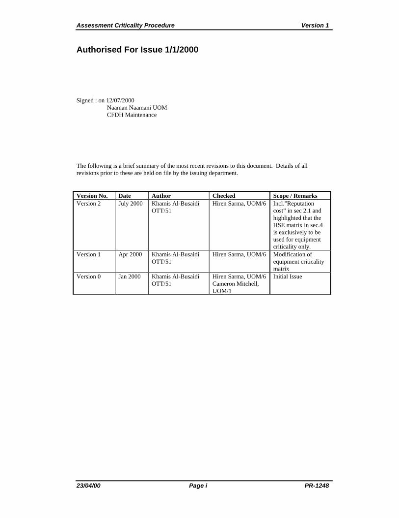
Assessment Criticality Procedure Version 1
23/04/00 Page i PR-1248
Authorised For Issue 1/1/2000
Signed : on 12/07/2000 Naaman Naamani UOM CFDH Maintenance
The following is a brief summary of the most recent revisions to this document. Details of all revisions prior to these are held on file by the issuing department.
Version No. Date Author Checked Scope / Remarks Version 2 July 2000 Khamis Al-Busaidi
OTT/51 Hiren Sarma, UOM/6
Incl.”Reputation cost” in sec 2.1 and highlighted that the HSE matrix in sec.4 is exclusively to be used for equipment criticality only.
Version 1 Apr 2000 Khamis Al-Busaidi OTT/51
Hiren Sarma, UOM/6
Modification of equipment criticality matrix
Version 0 Jan 2000 Khamis Al-Busaidi OTT/51
Hiren Sarma, UOM/6 Cameron Mitchell, UOM/1
Initial Issue
Version 1 Criticality Assessment Procedure
PR-1248 Page ii 23/04/00
Contents
Authorised For Issue 1/1/2000 ................................................................................................... i
Contents ..................................................................................................................................... ii
1 Introduction ......................................................................................................................... 1 1.1 Background ................................................................................................................ 1 1.2 Purpose ....................................................................................................................... 2 1.3 Distribution/Target Audience ..................................................................................... 2 1.4 Document Improvements ........................................................................................... 2
2 Criticality Assessment Methodology .................................................................................. 4 2.1 Asset and Production Loss ......................................................................................... 5 2.2 Safety .......................................................................................................................... 6 2.3 Environment ............................................................................................................... 7 2.4 Frequency of Demand (Occurrence) .......................................................................... 7 2.5 Functional Criticality Class Calculations ................................................................... 8
3 RCM Implementation ......................................................................................................... 9
4 Equipment Criticality ........................................................................................................ 10 4.1 Asset and Production Loss ....................................................................................... 10 4.2 Safety ........................................................................................................................ 10 4.3 Environment ............................................................................................................. 10 4.4 Time Interval Between Failures ............................................................................... 11
Appendix A Example of Station Function Criticality .......................................................... 12
Appendix B Glossary of Definitions, Terms and Abbreviations ......................................... 13
ATTACHMENT User Feedback Sheet ................................................................................. 14

Criticality Assessment Procedure Version 1
23/04/00 Page 1 PR-1248
1 Introduction
1.1 Background
Maintenance spending represents a significant percentage of total costs and, more importantly, of controllable costs across many industries. The benefits of maintenance excellence go beyond cost control to affect multiple performance dimensions of the organisation. These benefits are not trade offs and can be concurrent outcomes of maintenance improvement programs: -
• Lower direct maintenance cost
• Higher capital and labour productivity
• Reduced risk of catastrophic failure
Achieving maintenance excellence should be viewed as an evolutionary process where the End State is the cost-effective elimination of defects through the use of equipment specific maintenance approaches, e.g. fig.1.1. A continuous maintenance improvement cycle is obtained by continuously implementing the following steps: -
1. Determine operational business requirement.
2. Identify possible system designs and maintenance options.
3. Determine optimum maintenance strategies.
4. Monitor system performance and maintain strategy effectiveness.
Figure 1.1: Shell Maintenance Optimization
Define Operationalbusiness requirements
Identify possible systemdesigns and maintenanceoptions
Monitor system performanceand maintenance strategyeffectiveness
Determine optimummaintenance strategies
1-INTEGRITY-PRODUCTION-COSTS
2 RELIABILITY CENTREDMAINTENANCE
3 SYSTEMEFFECTIVENESS MODELLING
4PERFORMANCE MEASUREMENT
ADJUST
SET MAINTENANCE OBJECTIVES
IMPLEMENT OPTIMUM STRATEGIES
UPDATE WITHOPTIMUM STRATEGIES
Maintenance Optimization
INPUT RCM BASED STRATEGIES
Criticality
Assessment
Version 1 Criticality Assessment Procedure
PR-1248 Page 2 23/04/00
One of the recognised approaches to establish the maintenance requirements for any equipment is the use of Reliability Centred Maintenance (RCM). It is based on determining what must be done to ensure that the equipment fulfils its intended functions in its current operating context. RCM differs from previous maintenance thinking in two main ways; it focuses on the function of equipment rather than the equipment itself, and it generates maintenance activities designed to avoid or mitigate the consequence of failure.
Prior to applying RCM, the critical functions of selected assets are filtered in terms of Asset (Production), Safety and Environment criticality by Criticality Assessment Analysis which is described in this procedure. Under each critical function, the criticality is further defined in terms of individual equipment. Reference may be made to the PDO Risk Management Code of Practice CP-131 and to the DEP 32.80.10.10-PDO titled Classification and Implementation of Instrumented Protective Function.
1.2 Purpose
Criticality Assessment helps in determining what functions and equipment tags are critical and those which need to have Reliability Centered Maintenance (RCM) analysis carried out. It identifies and focuses on those items which are critical, not only in terms of maximising asset flow (production) but also potential risk to safety, and the environment.
Reliability Centered Maintenance (RCM) and Risk Based Inspection (RBI) are defined as “techniques used to determine the maintenance requirements of any physical asset in its operating context”. RCM and RBI are then applied in detail to these critical functions. The maintenance strategy/requirements for less and/or non-critical functions are then recommended using reference data already available for similar equipment. However, the operating context of these functions must be considered on a case by case basis while making such recommendations. Figure 1.2 depicts the relationship between criticality assessment and maintenance strategy development.
1.3 Distribution/Target Audience
The primary target audiences of this criticality assessment procedure are the Reliability Engineers, Maintenance Engineers, Project Engineers, CDFP’s, Discipline Engineers and Asset Team members involved in the planning, development and operational activities relevant to the particular asset.
1.4 Document Improvements
The custodian of this document is UOM/7. If you have any concerns or recommended improvements please contact OTT/51 or UOM/7.

Criticality Assessment Procedure Version 1
23/04/00 Page 3 PR-1248
Criticality Assessment
IPF/RCM IPF Results
Existing Facilities Existing New Facilities or New Facilities
Compare Epmars
Identify Cost Benefits & Agree with Asset teams where Improvement could be achieved.
Prepare - WSNS Select MCPS
Update EPMARS
Fig. 1.2: The relationship between RCM and the Criticality Assessment.

Version 1 Criticality Assessment Procedure
PR-1248 Page 4 23/04/00
2 Criticality Assessment Methodology
The Criticality Assessment is performed by determining the potential impact on the functions of a group of assets against the following criteria: -
Production and asset - The effect on production output and asset loss.
Safety – The direct or indirect personnel risk or equipment damage.
Environment - The effect on the local environment.
Frequency of occurrence - Failure frequency (reciprocal of Mean Time Between Failure).
The results of the initial assessment should be updated following commissioning of additional assets on site, further failure occurrences and/or more operational data. These results should be sorted to understand the importance of each function in terms of its impact on the Environment, Safety or Production criticality.
The following documents were referred to during the preparation of the criticality assessment procedure;
1. Risk Management Code of Practice, CP-131
2. DEP 32.80.10.10-PDO titled Classification and Implementation of Instrumented Protective Function.
3. LNG documents titled “Maintenance and Integrity Strategy Development”(LNG-9-0001-090-F1-4 and LNG-F1-SP-1-017).
4. EP Maintenance Management Guides (SIEP 98-5200/5215).
The functional criticality is done according to the risk matrix shown below. This matrix is the same as the PDO risk matrix described in the Risk Management Code of Practice CP-131. It should be noted however that since the magnitude of cost involved in the repair and upkeep of equipment is far lower than that involved in the original risk matrix (CP-131), the values in the asset column have been scaled down as per DEP 32.80.10.10-PDO. (see sections 2.1 to 2.4 for description)

Criticality Assessment Procedure Version 1
23/04/00 Page 5 PR-1248
A > 100 Year
B 20 - 100 Year
C 4 - 20 Year
D 0.5 - 4 Year
E 0 - 0.5 Year
Rating Environment Safety Assets Never heard of but could feasible occur
Does not occur during the lifetime of the facility
Normal demand when variables are controlled
Occurs once between maintenance shut-downs
Occurs several times a year
1 No/slight effcet No/slight injury
No/slight effcet
2 Minor effcet Minor injury
Minor effcetLow
3 Localised effect Major injury
Localised effect Medium
4 Major effect Single fatality
Major effectHigh
5 Massive effect Multiple fatality
Massive effectExtreme
Frequency of Demand (occurrence)Consequence
2.1 Asset and Production Loss
A more detailed description of the potential production and equipment loss selections is indicated in the table below. Damage refers to direct hardware replacement and repair cost and also to consequential losses due to down time.
Cat Potential impact Description (refer to DEP 32.80.10.10-PDO)
1 No/Slight effect No disruption to operation, no operational upset or no damage to assets. (total loss value less than US$ 1,000)
2 Minor effect Brief disruption, minor operational upset or minor damage to assets. (total loss value less than US$ 100,000)
3 Localised effect Partial shutdown, moderate operational upset or moderate damage to assets (total loss value less than US$ 1M)
4 Major effect Partial operation loss, major operational upset or major damage to assets (total loss value less than US$ 10M)
5 Massive effect Substantial or total loss of operations, damage causing major loss of containment or damage to essential assets (total loss value in excess of US$ 10M)
The asset and production loss calculation taking four main elements into account:
Total loss value = Production loss + Reprocessing cost + Reputation Cost (Applicable only for Gas plants) + Repair cost + Own labour cost.

Version 1 Criticality Assessment Procedure
PR-1248 Page 6 23/04/00
Where:
• Production loss is the deferred income (no or downgraded production) plus the product wasted (e.g. flared, spilled).
• Reprocessing cost is the cost (energy, tankage, etc.) required for reprocessing of off-spec. product or waste.
• Reputation cost: For Government Gas Plants viz. Yibal-GGP, LNG Upstream and Barik Gas station; the reliability of gas production in terms of quality and quantity of gas produced is of very high importance. The impact of faiure of a particular asset on the quality and quantity of gas produced shall be quantified under this “Reputation Cost”.
• Repair cost is the cost incurred to have the damage repaired or assets replaced.
• Own labour cost is the cost (hours etc.) of the owner’s personnel involved in the incident
From the calculated total loss value, the (asset and production) loss consequence category can be established from the above table.
2.2 Safety
A more detailed description of the safety effect is indicated in the table below.
Cat Potential impact Description (refer PDO HSE Risk assessment Matrix)
1 No/Slight injury No safety effect or slight injury or health effects (including first aid case and medical treatment case) - Not affecting work performance or causing disability.
2 Minor injury Minor injury or health effects (Lost Time Injury) – Affecting work performance, such as restriction to activities (Restricted Work Case) or a need to take a few days to fully recover (Lost Workday Case). Limited health effects, which are reversible, e.g. skin irritation, food poisoning.
3 Major injury Major injury or health effects (including Permanent Partial Disability) – Affecting work performance in the longer term, such as a prolonged absence from work. Irreversible health damages without loss of life, e.g. noise induced hearing loss, chronic back injuries.
4 Single fatality Single fatality – From an accident or occupational illness (poisoning, cancer).
5 Multiple fatality Multiple fatalities - From an accident or occupational illness (poisoning, cancer).
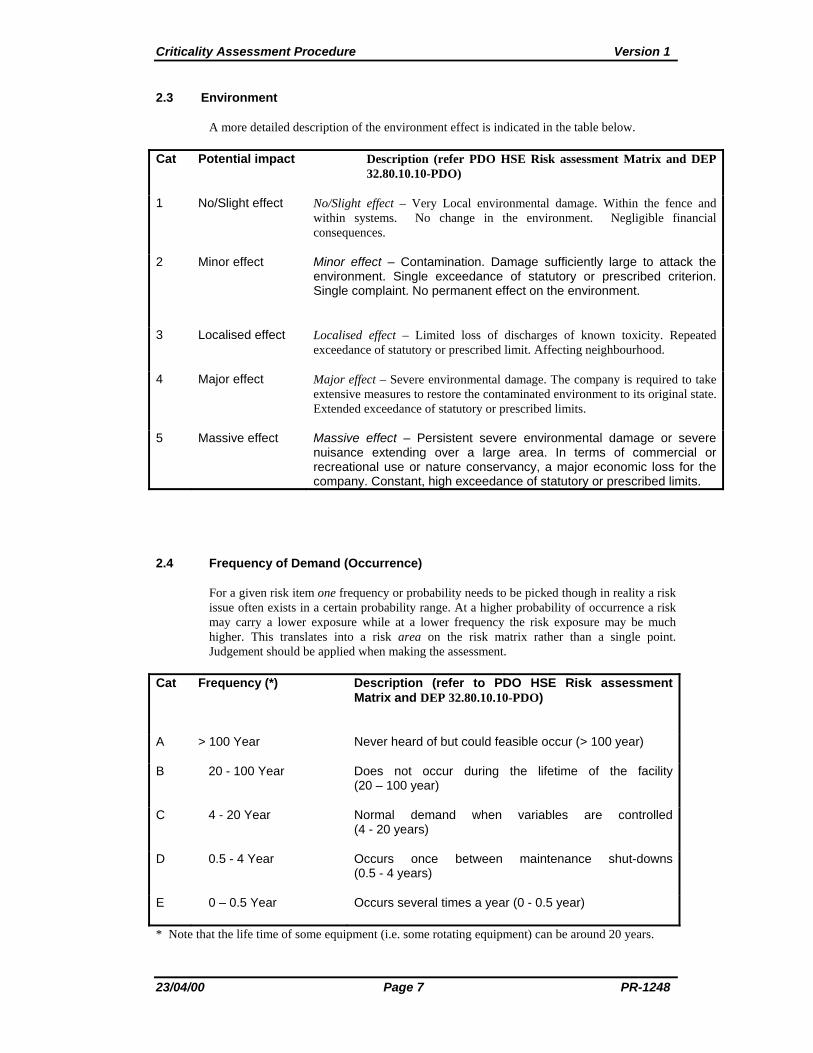
Criticality Assessment Procedure Version 1
23/04/00 Page 7 PR-1248
2.3 Environment
A more detailed description of the environment effect is indicated in the table below.
Cat Potential impact Description (refer PDO HSE Risk assessment Matrix and DEP 32.80.10.10-PDO)
1 No/Slight effect No/Slight effect – Very Local environmental damage. Within the fence and within systems. No change in the environment. Negligible financial consequences.
2 Minor effect Minor effect – Contamination. Damage sufficiently large to attack the environment. Single exceedance of statutory or prescribed criterion. Single complaint. No permanent effect on the environment.
3 Localised effect Localised effect – Limited loss of discharges of known toxicity. Repeated exceedance of statutory or prescribed limit. Affecting neighbourhood.
4 Major effect Major effect – Severe environmental damage. The company is required to take extensive measures to restore the contaminated environment to its original state. Extended exceedance of statutory or prescribed limits.
5 Massive effect Massive effect – Persistent severe environmental damage or severe nuisance extending over a large area. In terms of commercial or recreational use or nature conservancy, a major economic loss for the company. Constant, high exceedance of statutory or prescribed limits.
2.4 Frequency of Demand (Occurrence)
For a given risk item one frequency or probability needs to be picked though in reality a risk issue often exists in a certain probability range. At a higher probability of occurrence a risk may carry a lower exposure while at a lower frequency the risk exposure may be much higher. This translates into a risk area on the risk matrix rather than a single point. Judgement should be applied when making the assessment.
Cat Frequency (*) Description (refer to PDO HSE Risk assessment Matrix and DEP 32.80.10.10-PDO)
A > 100 Year Never heard of but could feasible occur (> 100 year)
B 20 - 100 Year Does not occur during the lifetime of the facility (20 – 100 year)
C 4 - 20 Year Normal demand when variables are controlled (4 - 20 years)
D 0.5 - 4 Year Occurs once between maintenance shut-downs (0.5 - 4 years)
E 0 – 0.5 Year Occurs several times a year (0 - 0.5 year)
* Note that the life time of some equipment (i.e. some rotating equipment) can be around 20 years.
Version 1 Criticality Assessment Procedure
PR-1248 Page 8 23/04/00
2.5 Functional Criticality Class Calculations
Each station is divided into functions (Operation Packages) by using the PEFS and PFS. A criticality assessment sheet, with all functions listed within the station, is completed for each station as shown in appendix A. A desktop exercise is arranged with the relevant discipline maintenance/operations personnel, to agree to the criticality class for each of the Asset (Production), Safety and Environment per function; i.e. Low, Medium, High or Extreme. (see the risk matrix in section 2)
It should be emphasised that one representative at least from each core discipline (Instrument, Electrical, Mechanical, Production and preferably HSE) shall be part of the exercise. It is also recommended that one representative from the Engineering design team is part of the team. In the case of a new facility, this is very important. The team shall be led by an experienced Reliability Engineer.

Criticality Assessment Procedure Version 1
23/04/00 Page 9 PR-1248
3 RCM Implementation
RCM is implemented based on the functional criticality classes obtained as stated in section 2.5. For each function, if the criticality class of Asset, Safety Or Environment is High OR Extreme (coloured blue or red in the matrix), then RCM will be implemented on that function. If none of the Asset, Safety Or Environment classes of the function is High OR Extreme, then RCM will NOT be implemented on that function.

Version 1 Criticality Assessment Procedure
PR-1248 Page 10 23/04/00
4 Equipment Criticality
If RCM is decided to be applied, then the functional criticality is drilled down further by determining Equipment Criticality taking into account the redundancy of the equipment. This is done during the RCM analysis exercise stated in section 2.5. The equipment criticality is applied in the same way as the functional criticality but on individual items of equipment and using the risk matrix shown below in which, the frequency of failures has been scaled down to reflect the failure and life time of equipment in the field.
The criticality matrix shown below shall be exclusively used for determining equipment criticality only.
Three criticality classes are given for Assets, Safety and Environment. The Safety and Environment criticality classes will be the same as those classes obtained during the functional criticality for that particular function which the equipment falls under. The Asset criticality class may reduce if there is redundancy on the equipment. Depending on the number of standby units, the production and deferment loss will reduce and so the risk will decrease.
In case where RCM methodology is not applied for function analysis, individual equipment criticality can be determined by using the same methods outlined above.
Rating Environment Safety Assets
1 No/slight effect No/slight injury
No / slight effect
2 Minor effect Minor injury
Minor effectLow
3 Localized effect Major injury
Localized effect Medium
4 Major effect Single fatality
Major effectHigh
5 Massive effect Multiple fatality
Massive effectExtreme
Time Interval between Failures (T)Consequence A
T >= 10 Years B 5 =< T < 10 Years
C 2 =< T < 5 Years
D 0.5 < T < 2 Years
E T <= 0.5 Years
4.1 Asset and Production Loss
Refer to section 2.1.
4.2 Safety
Refer to section 2.2.
4.3 Environment
Refer to section 2.3.

Criticality Assessment Procedure Version 1
23/04/00 Page 11 PR-1248
4.4 Time Interval Between Failures
For a given risk item one frequency or probability needs to be picked though in reality a risk issue often exists in a certain probability range. At a higher probability of occurrence a risk may carry a lower exposure while at a lower frequency the risk exposure may be much higher. This translates into a risk area on the risk matrix rather than a single point. Judgement should be applied when making the assessment.
Cat Interval (*) Description
A 10 years or more Time interval between failures is 10 years or more
B 5 =< T < 10 Years Time interval between failures is 5 years or more
C 2 =< T < 5 Years Time interval between failures is 2 years or more
D 0.5 < T < 2 Years Time interval between failures is more than 6 months
E 0.5 year or less Time interval between failures is 6 months or less
* Note this was scaled down to reflect the failure and life time of field equipment.

Version 1 Criticality Assessment Procedure
PR-1248 Page 12 23/04/00
Appendix A Example of Station Function Criticality
Criticality Assessment Procedure Version 1
23/04/00 Page 13 PR-1248
Appendix B Glossary of Definitions, Terms and Abbreviations
CP Code of Practice LNG Liquidify Natural Gas EC Environmental Criticality EI Environmental Impact EP, E&P Exploration & Production EPMARS Exploration & Production Maintenance Administration and
Reporting System. EWMS Engineering Work Management System FP Failure Probability HSE Health Safety and Environment IPF Instrumented Protective Function MCP Maintenance Craft Procedure. MTBF Mean Time Between Failure. PC Production Criticality PD Production Downtime PDO Petroleum Development Oman PEFS Process Engineering Flow scheme PFS Process Flow Scheme. PI Production Impact RC Repair Cost. RCM Reliability Centered Maintenance SC Safety Criticality SIEP SRCM
Shell International Exploration & Production Co. Shell (Proprietary) Reliability Centered Maintenance.
SI Safety Impact. WSNS Work Specifications Numbers.

Version 1 Criticality Assessment Procedure
PR-1248 Page 14 23/04/00
ATTACHMENT User Feedback Sheet
OPERATIONS PROCEDURES
USER FEEDBACK SHEET
Any user who identifies an error, inaccuracy or ambiguity in these Operations Procedures documents is requested to advise the custodians in the Systems & Information Section by returning this page (or copy) with his comments.
Volume: Part:
User name: Ref. Ind: Date:
New Operations Standard or Practice required: Yes / No (delete as applicable)
New Procedure, Name or Error Location : e.g. PRnumber, page, paragraph.
New Procedure/ Comment / Error / Suggestion
Scope of work for CMMS and CCMS
Doc. No: ZAU-84-104810 -VA-6793-20001-0000
APPENDIX-V
REVISION: 02 Date: 03.06.2013
APPENDIX IV
E-SPIR 2000 Procedure & Project Documents Requirement
PR-1443 (SPIR PROCEDURE AND PROJECT DOCUMENTS REQUIREMENT)
1
UNRESTRICTED DOCUMENT ID: PR-1443 OCTOBER 2003 FILING KEY:
Petroleum Development Oman L.L.C.
E-SPIR 2000 Procedure & Project Documents Requirement (Electronic Spare Parts list and Interchange ability Record)
Procedures
KEYWORDS: E-SPIR, PR-1443 Authorized for Issue Second Revision: 01/07/2009 Signed: ----------------------------------, Technical Eng Consultancy Manager - UEC This document is the property of Petroleum Development Oman, LLC. Neither the whole nor any part of this document may be disclosed to others or reproduced, stored in a retrieval system or transmitted in any form by any means (electronic, mechanical, reprographic recording or otherwise) without prior written consent of the owner.
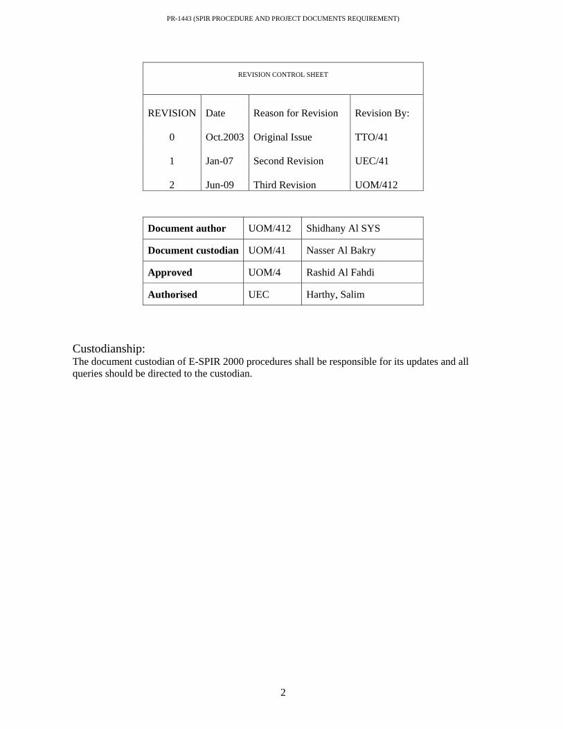
PR-1443 (SPIR PROCEDURE AND PROJECT DOCUMENTS REQUIREMENT)
2
Custodianship: The document custodian of E-SPIR 2000 procedures shall be responsible for its updates and all queries should be directed to the custodian.
REVISION CONTROL SHEET
REVISION Date Reason for Revision Revision By:
0 Oct.2003 Original Issue TTO/41
1 Jan-07 Second Revision UEC/41
2 Jun-09 Third Revision UOM/412
Document author UOM/412 Shidhany Al SYS
Document custodian UOM/41 Nasser Al Bakry
Approved UOM/4 Rashid Al Fahdi
Authorised UEC Harthy, Salim
PR-1443 (SPIR PROCEDURE AND PROJECT DOCUMENTS REQUIREMENT)
3
Table of Contents
No Description Page No
Title Cover Page 1 Document Revision Status & Authorization 2 Table of Contents 3 1 Introduction to E-SPIR 2000 4 1.1 Background 4 1.2 Purpose 4 1.3 Distribution & Target Audience 4 2 Project Documentation Requirement for E-SPIR 5 2.1 Scope 5 2.2 Principles 5 2.3 Procedure Description 5 2.4 Funding of spare parts 5 2.5 Roles and Responsibilities 6 & 7 2.6 E-SPIR Form 8 2.7 References 9 2.8 Request for Stocking Spare parts 9 2.9 Request for stocking spare parts (RFSS) 10 3.0 Motor Name Plate Technical Data 11 3.1 Rechargeable batteries 12 Appendix A (Definitions) Appendix B (Abbreviations) Appendix C (Project Material & SPIR Process Flowchart) Appendix D (SPIR Documentation Conformity Review Process) Appendix E ( Procedure Process, Activities & Responsibilities) Appendix F (Rotating Equipments) Appendix G (Static Equipments) Appendix H (Process Instrumentation) Appendix I (Electrical Equipment)

PR-1443 (SPIR PROCEDURE AND PROJECT DOCUMENTS REQUIREMENT)
4
1. Introduction to E-SPIR 2000 Electronic Spare Parts and Interchangeability Record is a software package for obtaining spare parts information from equipment suppliers in a standard format. It supports the purchaser in reviewing and selecting spare parts. 1.1 Background Project engineering code of practice (CP-117) stipulates the mandatory requirement of Consultants, Manufacturers, Suppliers and Vendors of equipment or plant supplied to and installed in PDO facilities to provide spare parts recommendation on E-SPIR forms supported with all relevant documentation. 1.2 Purpose The purpose of this procedure is to describe the process of spare parts management and the mandatory requirements by project engineers in the submission E-SPIR forms along with a consistent set of other supporting relevant documentation (see appendix G, H & I) to Head, Spare Parts Management (UOM/41). 1.3 Distribution/Target Audience This document is primarily intended for PDO project engineers. It is also made available to PDO operation engineers, contracting/procurement department personnel and to approved consultants, manufacturers, suppliers and vendors of equipment and material.

PR-1443 (SPIR PROCEDURE AND PROJECT DOCUMENTS REQUIREMENT)
5
2 Project Documentation requirement for E-SPIR 2.1 Scope This procedure is to be followed to ensure information that is entered into the E-SPIR forms and the project documentation (see appendixes F, G, H & I ) as submitted by the consultant/manufacturer/vendors/suppliers along with the E-SPIR forms meets the obligations as mentioned in PR-1443 & DEP 70.10.90.11-Gen. 2.2 Principles The basic principle of this procedure is to provide a clear well defined document that lists out the requirement in filling the standard E-SPIR form correctly and providing other relevant supporting documents. The documents provided by the manufacturer/supplier/vendor are to be used as a source of spare part data for clearly identifying the spare parts and interchangeability thus assisting to determine the holding of the optimum quantity necessary to safeguard cost effective operations of equipment/plant. The decision to stock or not to stock is made by applying the Decision Rule as described in DEP 70.10.90.11- Gen. 2.3 Procedure Description The procedures presented as flowchart (appendixes C, D &E) constitutes PR-1443. 2.4 Funding of Spare Parts Commissioning and initial start up spares including long lead Capitalized Insurance Spares (if any) are to be ordered along with the main project equipment on project CAPEX budget and shall be available at site prior to commissioning. Capitalized Insurance spares are stocked in the company’s warehouses at zero value. End users using these spares have to provide a RFA to replenish them. Operating supply spares listed and recommended to stock under Materials Catalogue Request Form (MCRF) are authorized by Head Spare Parts Management (UOM/41). They are further approved for procurement and stocking by Head, Procurement (FPO) against Contracting & Procurement department’s Capital Budget (stock account) and stocked at company’s warehouses at MAF, Fahud and Marmul as per MCRF. The cost of spares are charged to the end users OPEX budget at the time of issue for usage and replenished by C&P (contracting & procurement department) against stock account for subsequent availability and requirement of end users.
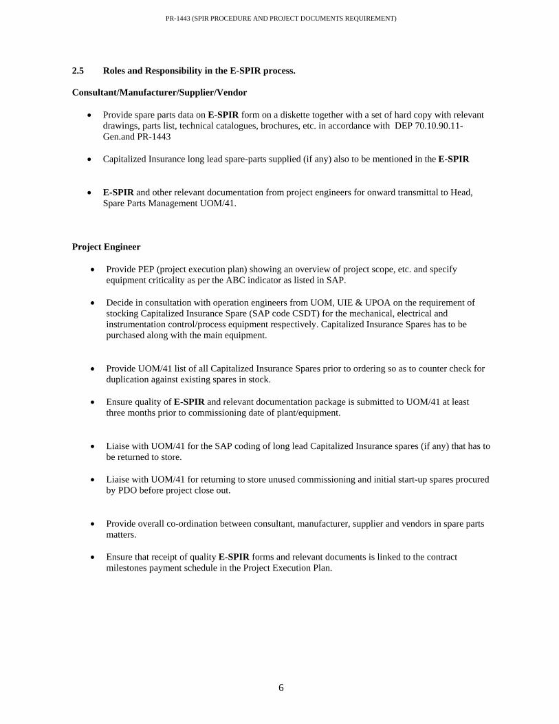
PR-1443 (SPIR PROCEDURE AND PROJECT DOCUMENTS REQUIREMENT)
6
2.5 Roles and Responsibility in the E-SPIR process. Consultant/Manufacturer/Supplier/Vendor
• Provide spare parts data on E-SPIR form on a diskette together with a set of hard copy with relevant drawings, parts list, technical catalogues, brochures, etc. in accordance with DEP 70.10.90.11-Gen.and PR-1443
• Capitalized Insurance long lead spare-parts supplied (if any) also to be mentioned in the E-SPIR
• E-SPIR and other relevant documentation from project engineers for onward transmittal to Head,
Spare Parts Management UOM/41.
Project Engineer
• Provide PEP (project execution plan) showing an overview of project scope, etc. and specify equipment criticality as per the ABC indicator as listed in SAP.
• Decide in consultation with operation engineers from UOM, UIE & UPOA on the requirement of
stocking Capitalized Insurance Spare (SAP code CSDT) for the mechanical, electrical and instrumentation control/process equipment respectively. Capitalized Insurance Spares has to be purchased along with the main equipment.
• Provide UOM/41 list of all Capitalized Insurance Spares prior to ordering so as to counter check for
duplication against existing spares in stock. • Ensure quality of E-SPIR and relevant documentation package is submitted to UOM/41 at least
three months prior to commissioning date of plant/equipment.
• Liaise with UOM/41 for the SAP coding of long lead Capitalized Insurance spares (if any) that has to
be returned to store. • Liaise with UOM/41 for returning to store unused commissioning and initial start-up spares procured
by PDO before project close out.
• Provide overall co-ordination between consultant, manufacturer, supplier and vendors in spare parts
matters. • Ensure that receipt of quality E-SPIR forms and relevant documents is linked to the contract
milestones payment schedule in the Project Execution Plan.

PR-1443 (SPIR PROCEDURE AND PROJECT DOCUMENTS REQUIREMENT)
7
Spare Parts Analyst (UOM/41X)
• Technically review, scrutinize and identify electrical spare parts from vendor SPIR forms submitted by project engineers. Compare/verify with existing spares database to avoid duplication and over stocking. Decide and recommend critical new spares for optimum stocking by challenging the vendor’s recommended spares and quantity.
• • Draft technical specification of spare parts, prepare coding list, raise stock proposal for authorization
by Head Spare Parts Management (UOM/41) and submit to Contracting and Procurement department for procuring and stocking action.
• Create, maintain and update Bill of Material (BOM) of spare parts and link it to equipment in SAP
system. This information can be used by end users to view spare parts data of installed equipments in PDO.
• Technical evaluations of spare parts quotations deviating from the standard purchase order text.
• Helpdesk and technical support to asset field personnel, operation support engineers and project
engineers on spare parts matters and advise substitutes during emergencies.
• Liaison with project engineers on the selection of long lead capitalized insurance spares for ordering on project CAPEX account.
• Technical investigation/liaison with end users and procurement department on spare parts COM
(criticism of material) form SAP Content Group (FPP/3)
• Corporate focal point between PDO and SAP Blue Print Global Catalogue Kuala Lumpur in the creation/amendment/deletion of SAP material number from the MCRF (Materials Catalogue Request Form) for HIBE & CSDT material.
• Create/Amend/Delete/and maintain plant records Stock Analyst/Buyers (FPO/2X)
• Analyze, procure and stock spare parts as per the authorized MCRF (Materials Catalogue Request Form).
• Analyze and adjust minimum/maximum levels for existing stock as per consumption rate in
consultation with UOM/41X
Spares Categories and responsibilities:
Spares categories Responsibility of Purchase Budget Commissioning Spares Project Scope Capex Account
Capital Insurance Spares UEC/2 CFDH to Approve with UOM41 Involvement and
purchased via Project
Capex Account
2 Yearly / Operational Spares UOM41 Corporate Account
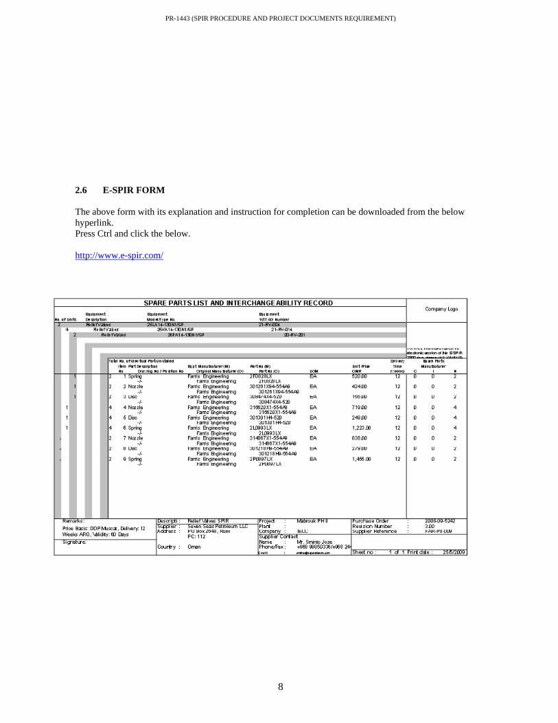
PR-1443 (SPIR PROCEDURE AND PROJECT DOCUMENTS REQUIREMENT)
8
2.6 E-SPIR FORM The above form with its explanation and instruction for completion can be downloaded from the below hyperlink. Press Ctrl and click the below. http://www.e-spir.com/
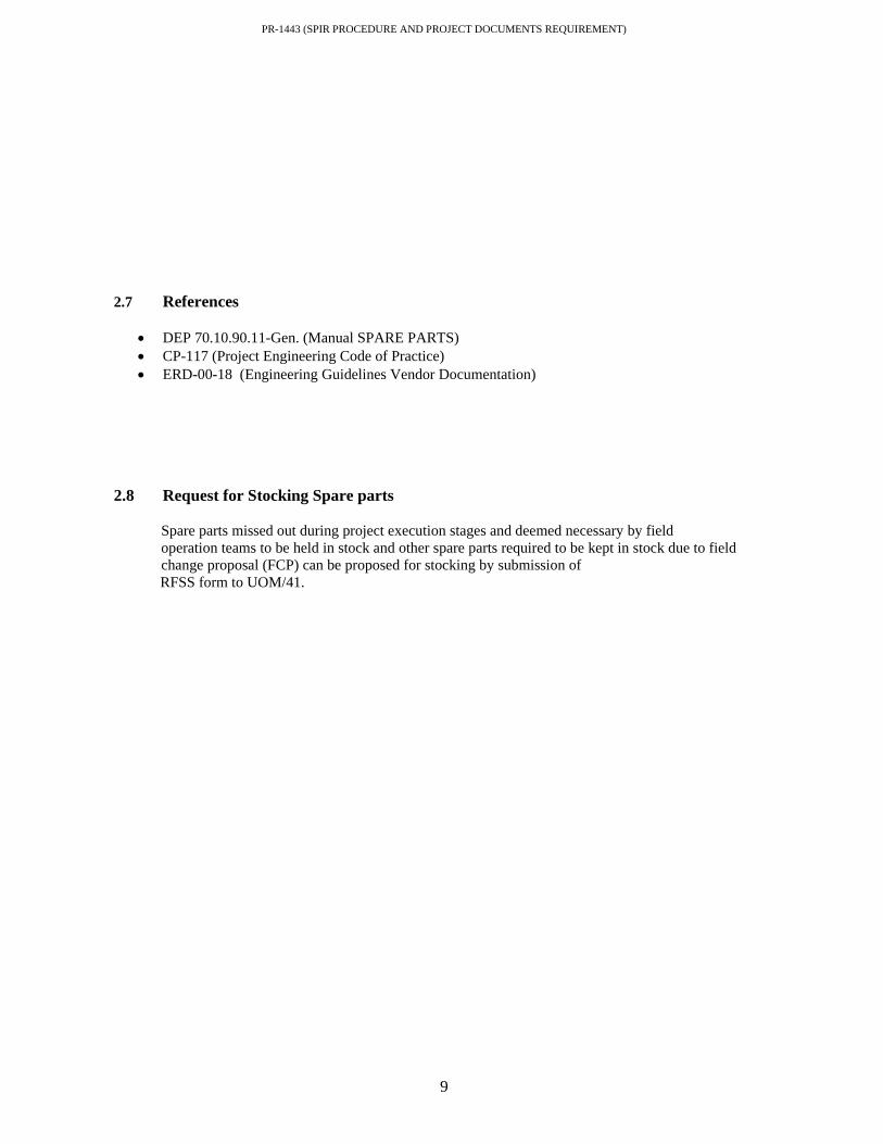
PR-1443 (SPIR PROCEDURE AND PROJECT DOCUMENTS REQUIREMENT)
9
2.7 References
• DEP 70.10.90.11-Gen. (Manual SPARE PARTS) • CP-117 (Project Engineering Code of Practice) • ERD-00-18 (Engineering Guidelines Vendor Documentation)
2.8 Request for Stocking Spare parts
Spare parts missed out during project execution stages and deemed necessary by field operation teams to be held in stock and other spare parts required to be kept in stock due to field change proposal (FCP) can be proposed for stocking by submission of
RFSS form to UOM/41.

PR-1443 (SPIR PROCEDURE AND PROJECT DOCUMENTS REQUIREMENT)
10
2.9 Request For Stocking of Spares Form (RFSS)
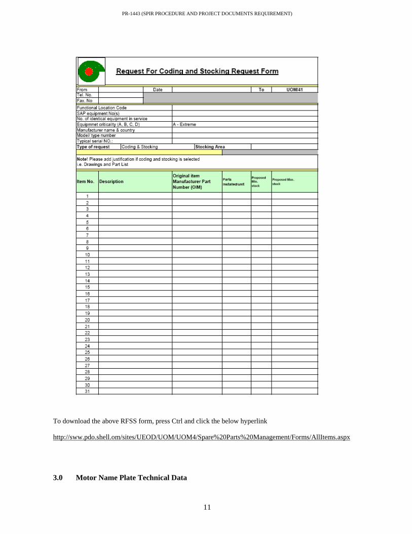
PR-1443 (SPIR PROCEDURE AND PROJECT DOCUMENTS REQUIREMENT)
11
To download the above RFSS form, press Ctrl and click the below hyperlink http://sww.pdo.shell.om/sites/UEOD/UOM/UOM4/Spare%20Parts%20Management/Forms/AllItems.aspx 3.0 Motor Name Plate Technical Data
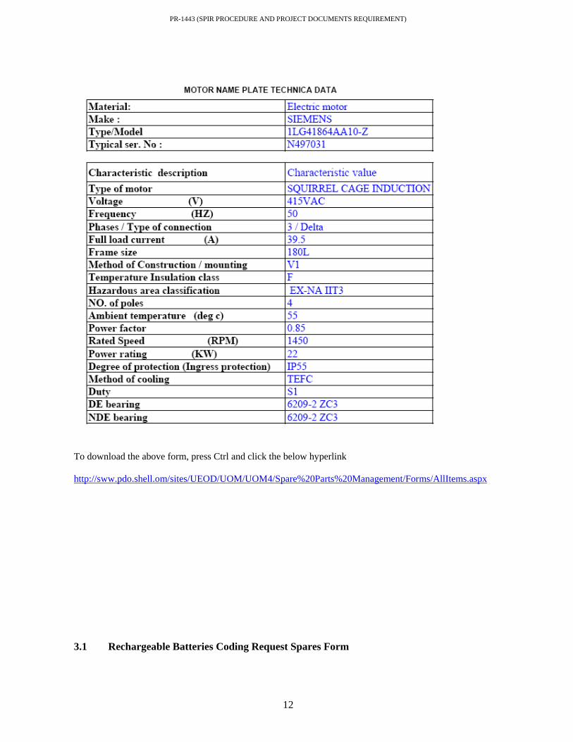
PR-1443 (SPIR PROCEDURE AND PROJECT DOCUMENTS REQUIREMENT)
12
To download the above form, press Ctrl and click the below hyperlink http://sww.pdo.shell.om/sites/UEOD/UOM/UOM4/Spare%20Parts%20Management/Forms/AllItems.aspx 3.1 Rechargeable Batteries Coding Request Spares Form

PR-1443 (SPIR PROCEDURE AND PROJECT DOCUMENTS REQUIREMENT)
13
To download the above form, press Ctrl and click the below hyperlink http://sww.pdo.shell.om/sites/UEOD/UOM/UOM4/Spare%20Parts%20Management/Forms/AllItems.aspx
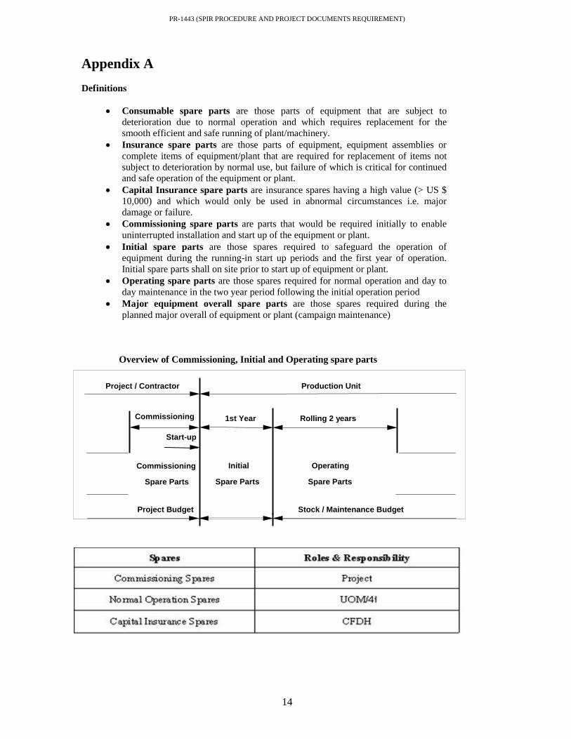
PR-1443 (SPIR PROCEDURE AND PROJECT DOCUMENTS REQUIREMENT)
14
Appendix A Definitions
• Consumable spare parts are those parts of equipment that are subject to deterioration due to normal operation and which requires replacement for the smooth efficient and safe running of plant/machinery.
• Insurance spare parts are those parts of equipment, equipment assemblies or complete items of equipment/plant that are required for replacement of items not subject to deterioration by normal use, but failure of which is critical for continued and safe operation of the equipment or plant.
• Capital Insurance spare parts are insurance spares having a high value (> US $ 10,000) and which would only be used in abnormal circumstances i.e. major damage or failure.
• Commissioning spare parts are parts that would be required initially to enable uninterrupted installation and start up of the equipment or plant.
• Initial spare parts are those spares required to safeguard the operation of equipment during the running-in start up periods and the first year of operation. Initial spare parts shall on site prior to start up of equipment or plant.
• Operating spare parts are those spares required for normal operation and day to day maintenance in the two year period following the initial operation period
• Major equipment overall spare parts are those spares required during the planned major overall of equipment or plant (campaign maintenance)
Overview of Commissioning, Initial and Operating spare parts
Commissioning Spare Parts
Initial
Spare Parts
Operating
Spare Parts
Project / Contractor Production Unit
Stock / Maintenance Budget Project Budget
1st YearCommissioning
Start-up
Rolling 2 years

PR-1443 (SPIR PROCEDURE AND PROJECT DOCUMENTS REQUIREMENT)
15
Appendix B Abbreviations
ABC Indicator
Equipment criticality i.e. A= Extreme B= High C= Medium D=Low
BOM
Bill Of Material
CSDT
Capitalized Insurance Spare
DEP
Design and Engineering Practice
FCP
Field Change Proposal
HIBE
Operating Supplies
MCRF
Materials Catalogue Request Form
OEM
Original Equipment Manufacturer
PEP
Project Execution Plan
PMSS
Project Material Strategy Sheet
RFA
Request For Authorization
RFSS
Request For Stocking Spares
SAP
System Application and Products
E-SPIR
Electronic Spare Parts list and Interchange ability Record

PR-1443 (SPIR PROCEDURE AND PROJECT DOCUMENTS REQUIREMENT)
16

PR-1443 (SPIR PROCEDURE AND PROJECT DOCUMENTS REQUIREMENT)
17

PR-1443 (SPIR PROCEDURE AND PROJECT DOCUMENTS REQUIREMENT)
18

PR-1443 (SPIR PROCEDURE AND PROJECT DOCUMENTS REQUIREMENT)
19

PR-1443 (SPIR PROCEDURE AND PROJECT DOCUMENTS REQUIREMENT)
20

PR-1443 (SPIR PROCEDURE AND PROJECT DOCUMENTS REQUIREMENT)
21

PR-1443 (SPIR PROCEDURE AND PROJECT DOCUMENTS REQUIREMENT)
22

PR-1443 (SPIR PROCEDURE AND PROJECT DOCUMENTS REQUIREMENT)
23

PR-1443 (SPIR PROCEDURE AND PROJECT DOCUMENTS REQUIREMENT)
24

PR-1443 (SPIR PROCEDURE AND PROJECT DOCUMENTS REQUIREMENT)
25
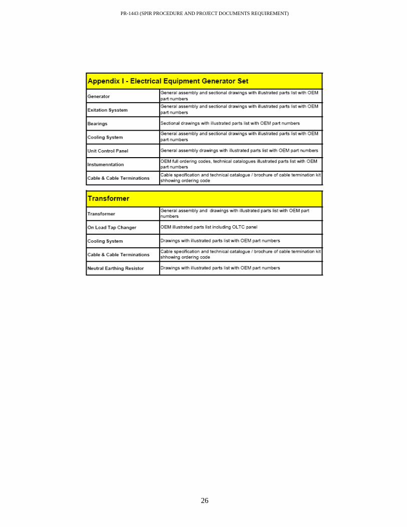
PR-1443 (SPIR PROCEDURE AND PROJECT DOCUMENTS REQUIREMENT)
26

PR-1443 (SPIR PROCEDURE AND PROJECT DOCUMENTS REQUIREMENT)
27

PR-1443 (SPIR PROCEDURE AND PROJECT DOCUMENTS REQUIREMENT)
28